

Page 1

COMPACT COMPONENT SYSTEM
EX-A10
Consists of RX-EXA10, SP-EXA10 and XV-EXA10
English
INSTRUCTIONS
For Customer Use:
Enter below the Model No. and Serial No.
which are located either on the rear,
bottom or side of the cabinet. Retain this
information for future refe rence.
Model No.
Serial No.
LVT1403-002B
[J, C, UJ]
Page 2

Warnings, cautions and others
(For U.S.A.)
The lightning flash with arrowhead symbol, within
an equilateral triangle is intended to alert the
user to the presence of uninsulated “dangerous
voltage” within the product’s enclosure that may
be of sufficient magnitude to constitute a risk of
electric shock to persons.
The exclamation point within an equilateral
triangle is intended to alert the user to the
presence of important operating and
maintenance (servicing) instructions in the
literature accompanying the appliance.
(For U.S.A.)
(For U.S.A.)
INFORMATION
This equipment has been tested and found to comply with the limits for a Class B digital device, pursuant to part 15 of
the FCC Rules. These limits are designed to provide reasonable protection against harmful interference in a residential
installation.
This equipment generates, uses and can radiate radio frequency energy and, if not installed and used in accordance
with the instructions, may cause harmful interference to radio communications. However, there is no guarantee that
interference will not occur in a particular installation. If this equipment does cause harmful interference to radio or
television reception, which can be determined by turning the equipment off and on, the user is encouraged to try to
correct the interference by one or more of the following measures:
Reorient or relocate the receiving antenna.
Increase the separation between the equipment and receiver.
Connect the equipment into an outlet on a circuit different from that to which the receiver is connected.
Consult the dealer or an experienced radio/TV technician for help.
(For U.S.A.)
Note to CATV system installer:
This reminder is provided to call the CATV system installer’s attention to Section 820-40 of the NEC which provides
guidelines for proper grounding and, in particular, specifies that the cable ground shall be connected to the grounding
system of the building, as close to the point of cable entry as practical.
G-1
Page 3

CAUTION
To reduce the risk of electrical shocks, fire, etc.:
1. Do not remove screws, covers or cabinet.
2. Do not expose this appliance to rain or moisture.
ATTENTION
Afin d’éviter tout risque d’électrocution, d’incendie, etc.:
1. Ne pas enlever les vis ni les panneaux et ne pas ouvrir le coffret de l’appareil.
2. Ne pas exposer l’appareil à la pluie ni à l’humidité.
CAUTION — F button!
Disconnect the mains plug to shut the power off completely (the
STANDBY lamp goes off).
The F button in any position does not disconnect the mains
line.
• When the system is on standby, the STANDBY lamp lights
red.
• When the system is turned on, the STANDBY lamp goes off.
The power can be remote controlled.
ATTENTION - Touche F!
Déconnectez la fiche d’alimentation secteur pour couper l’alimentation complètement (le témoin STANDBY s’éteint).
La touche F, dans n’importe quelle position, ne déconnecte
pas le système du secteur.
• Quand le système est en attente, le témoin STANDBY est
allumé en rouge.
• Quand le système est sous tension, le témoin STANDBY
s’éteint.
L’alimentation ne peut pas être télécommandée.
CAUTION
• Do not block the ventilation openings or holes.
(If the ventilation openings or holes are blocked by a
newspaper or cloth, etc., the heat may not be able to get out.)
• Do not place any naked flame sources, such as lighted
candles, on the apparatus.
• When discarding batteries, environmental problems must be
considered and local rules or laws governing the disposal of
these batteries must be followed strictly.
• Do not expose this apparatus to rain, moisture, dripping or
splashing and that no objects filled with liquids, such as vases,
shall be placed on the apparatus.
ATTENTION
• Ne bloquez pas les orifices ou les trous de ventilation.
(Si les orifices ou les trous de ventilation sont bloqués par un
journal un tissu, etc., la chaleur peut ne pas être évacuée
correctement de l’appareil.)
• Ne placez aucune source de flamme nue, telle qu’une bougie,
sur l’appareil.
• Lors de la mise au rebut des piles, veuillez prendre en
considération les problèmes de l’environnement et suivre
strictement les règles et les lois locales sur la mise au rebut
des piles.
• N’exposez pas cet appareil à la pluie, à l’humidité, à un
égouttement ou à des éclaboussures et ne placez pas des
objets remplis de liquide, tels qu’un vase, sur l’appareil.
G-2
Page 4

Warnings, cautions and others (continued)
(For U.S.A. or Canada models)
IMPORTANT FOR LASER PRODUCTS / IMPORTANT POUR PRODUITS LASER
1. CLASS 1 LASER PRODUCT
2. CAUTION: Do not open the top cover. There are no user serviceable parts inside the
unit; leave all servicing to qualified service personnel.
3. CAUTION: VISIBLE AND / OR INVISIBLE CLASS 1M LASER RADIATION WHEN
OPEN. DO NOT STARE INTO BEAM OR VIEW DIRECTLY WITH OPTICAL
INSTRUMENTS.
4. REPRODUCTION OF LABEL: CAUTION LABEL, PLACED INSIDE THE UNIT.
1. PRODUIT LASER CLASSE 1
2. ATTENTION: N'ouvrez pas le couvercle supérieur. Il n'y a aucune pièce réparable par
l'utilisateur à l'intérieur de l'appareil; confiez toute réparation à un personnel qualifié.
3. ATTENTION: RAYONNEMENT LASER VISIBLE ET / OU INVISIBLE DE CLASSE 1M
UNE FOIS OUVERT. NE PAS FIXER LE FAISCEAU NI REGARDER DIRECTEMENT
AVEC DES INSTRUMENTS OPTIQUES.
4. REPRODUCTION DE L'ÉTIQUETTE: ÉTIQUETTE DE PRÉCAUTION PLACÉE À
L'INTERIEUR DE L'APPAREIL.
(For models other than U.S.A. or Canada models)
IMPORTANT FOR LASER PRODUCTS / IMPORTANT POUR PRODUITS LASER
1. CLASS 1 LASER PRODUCT
2. CAUTION: Do not open the top cover. There are no user serviceable parts inside the
unit; leave all servicing to qualified service personnel.
3. CAUTION: Visible and invisible laser radiation when open and interlock failed or
defeated. Avoid direct exposure to beam.
4. REPRODUCTION OF LABEL: CAUTION LABEL, PLACED INSIDE THE UNIT.
1. PRODUIT LASER CLASSE 1
2. ATTENTION: N'ouvrez pas le couvercle supérieur. Il n'y a aucune pièce réparable par
l'utilisateur à l'intérieur de l'appareil; confiez toute réparation à un personnel qualifié.
3. ATTENTION: Risque de radiations laser visible et invisible quand l'appareil est ouvert et
que le système de verrouillage ne fonctionne pas ou a été mis hors service. Évitez toute
exposition directe au rayon.
4. REPRODUCTION DE L'ÉTIQUETTE: ÉTIQUETTE DE PRÉCAUTION PLACÉE À
L'INTERIEUR DE L'APPAREIL.
G-3
Page 5

For Canada/pour le Canada
15
CAUTION: TO PREVENT ELECTRIC SHOCK, MATCH WIDE BLADE OF PLUG TO WIDE SLOT, FULLY INSERT.
ATTENTION: POUR EVITER LES CHOCS ELECTRIQUES, INTRODUIRE LA LAME LA PLUS LARGE DE LA FICHE
DANS LA BORNE CORRESPONDANTE DE LA PRISE ET POUSSER JUSQUAU FOND.
For Canada/pour le Canada
THIS DIGITAL APPARATUS DOES NOT EXCEED THE CLASS B LIMITS FOR RADIO NOISE EMISSIONS FROM
DIGITAL APPARATUS AS SET OUT IN THE INTERFERENCE-CAUSING EQUIPMENT STANDARD ENTITLED
“DIGITAL APPARATUS”, ICES-003 OF THE DEPARTMENT OF COMMUNICATIONS.
CET APPAREIL NUMERIQUE RESPECTE LES LIMITES DE BRUITS RADIOELECTRIQUES APPLICABLES AUX
APPAREILS NUMIRIQUES DE CLASSE B PRESCRITES DANS LA NORME SUR LE MATERIEL BROUILLEUR:
“APPAREILS NUMERIQUES”, NMB-003 EDICTEE PAR LE MINISTRE DES COMMUNICATIONS.
CAUTION — Proper Ventilation
To avoid risk of electric shock and fire and to protect from damage, locate the apparatus as follows:
Top/Front/Back/Sides: No obstructions should be placed in the areas shown by the dimensions below.
Bottom: Place on the level surface. Maintain adequate air path for ventilation by placing on
a stand with a height of 10 cm (3 ″) more.
15
16
In addition, maintain the best possible air circulation.
Attention: Ventilation correcte
Pour éviter tout risque d’électrocution et d’incendie, et pour ne pas endommager les appareils, placez-les
de la façon suivante:
Faces supérieure /avant / arrière / côtés : Aucune obstruction ne doit se trouver dans les zones
Bas : Placez l’appareil sur une surface plane. Maintenez une entrée
De plus, maintenez la meilleure circulation d’air possible.
indiquées par les dimensions ci-dessous.
d’air adéquate pour la ventilation en plaçant l’appareil sur un
support avec une hauteur d’au moins 10 cm
(3 ″)
16
.
Front view Side view
Vue avant Vue de c ôté
15 cm
15
(5 ″)
16
1 cm
7
( ″)
16
15 cm
15
(5 ″)
1 cm
7
( ″)
16
16
[European Union only]
[Union européenne seulement]
15 cm
15
(5 ″)
16
10 cm
(3 ″)
Front
Avant
15
16
15
15 cm (5 ″)
16
Wall or
obstructions
Mur, ou
obstruction
G-4
Page 6

Table of contents
Introduction
Supplied accessories ......................................2
Part description ...............................................3
DVD player ......................................................... 3
Receiver.............................................................. 4
Using the remote control .................................5
Inserting batteries into the remote control .......... 5
Operating the TV using the remote control......... 6
Preparation
Connections ....................................................7
Standard setup ................................................... 7
Connecting the antennas.................................... 7
Connecting the speakers.................................... 9
Connecting the receiver and the DVD player ... 10
Connecting other equipment............................. 11
Connecting a TV............................................... 12
Connecting the power cords............................. 13
Basic operations
Basic operations............................................14
Turning on/off the system ................................. 14
Setting the clock ............................................... 15
Dimmer ............................................................. 16
Adjusting the volume ........................................ 16
Turning off the sound temporarily (MUTING) ... 16
Adjusting the sound quality............................... 16
Adjusting the bass sound.................................. 17
Enhancing the playback sound
(CC CONVERTER) ........................................ 17
Listening to radio
Listening to radio broadcasts ........................18
Setting the AM tuner spacing (only for
models sold at post exchanges) ..................... 18
Selecting a radio station ................................... 18
Tuning in to a preset radio station .................... 19
Playing back DVDs/CDs
Basic operations of the DVD player ..............20
Playing back a DVD/CD ....................................20
Changing the display in the display window......23
Selecting a chapter/track using the number
buttons ............................................................23
Stopping playback .............................................23
Pausing playback ..............................................24
Advancing the picture frame by frame...............24
Fast reverse/fast forward search .......................24
Playing back from a position 10 seconds before
(One touch replay) ..........................................25
Slow motion playback ........................................25
Skipping to the beginning of a chapter/
track/file...........................................................25
Skipping at about 5 minute intervals..................26
Resuming playback ...........................................26
Selecting a track from the menu screen ............27
Convenient functions of the DVD player .......28
Locking DVD/CD ejection ..................................28
Playing back a DVD/CD in the desired order
(Program playback) .........................................28
Playing back a DVD/CD in a random order
(Random playback).........................................30
Playing back a DVD/CD repeatedly
(Repeat playback)...........................................30
Playing back a specified part repeatedly
(A-B repeat playback) .....................................31
Saving the playback settings for next time ........31
Selecting the subtitles........................................32
Selecting the audio language............................32
Selecting the view angle....................................33
Magnifying the picture (ZOOM) .........................33
Adjusting the picture quality (VFP) ....................34
Playing back the bonus group ...........................34
Browsable still pictures (B.S.P.) ........................35
Creating realistic sound (3D PHONIC)..............35
Using the status bar and the menu bar .............36
Changing the initial settings with the
preference screen .....................................38
Basic operations ................................................38
LANGUAGE.......................................................38
PICTURE...........................................................39
AUDIO ...............................................................39
OTHERS............................................................39
1
Page 7

C
Supplied accessories
Introduction
Listening to the sound of other
audio equipment
Listening to the sound of other audio
equipment ...................................................41
Timer
Timer .............................................................42
Using the sleep timer........................................ 42
Using the playback timer .................................. 43
Reference
Using the AV COMPU LINK function ............45
Connection and setup....................................... 45
Operation .......................................................... 45
Special cautions ............................................46
Notes on handling............................................. 46
About DVDs/CDs...........................................47
Playable DVD/CD types.................................... 47
Disc structure.................................................... 49
Troubleshooting.............................................50
Language codes............................................51
Specifications ................................................52
Check to be sure you have all of the supplied
accessories.
The number in parentheses is the quantity of the
items supplied. If anything is missing, contact your
dealer immediately.
• Remote control (1)
• Batteries (2)
• FM antenna (1)
• AM loop antenna (1)
• Speaker cords (4)
• Audio cord (1)
• Optical digital cord (1)
• Synchronization cord (1)
• Composite video cord (1)
• AC plug adaptor* (2)
NOTE
* The AC plug adaptor is not supplied for U.S.A. and
Canada models.
AUTION
• Do not fold the optical digital cord as this may
damage the inner wire.
Introduction
How to read this manual
• This manual explains the operations assuming
that you will use the remote control. Some buttons
on the receiver or the DVD player are the same as
those on the remote control. You can use either
button in this case.
• Some diagrams in this manual are simplified or
exaggerated for the purpose of explanation.
• You can operate some functions differently from
the explanation given in this manual.
• The following marks refer to the usable discs for
the explained function.
• “DVD VR” means a DVD recorded in DVD Video
Recording (DVD VR) format.
• “VCD” stands for “Video Compact Disc”.
• “SVCD” stands for “Super Video Compact Disc”.
• An “ASF” disc means a disc recorded in
“Advanced Systems Format”.
2
Page 8

S
Part description
The numbers refer to the pages in which the parts are explained.
DVD player
Front panel
13, 14
14
Rear panel
10
13
ee “Display window” shown below.
5
23–26, 28
20, 2420, 2820
45
10
10 47 12 12
12
Display window
The receiver and the DVD player use the same design for their display windows.
21, 22
21, 22,
21, 22
21, 27 28
21, 22, 29
29
34, 35 13
30
30 31 31
3
Page 9

The numbers refer to the pages in which the parts are explained.
Receiver
Front panel
See “Display window” shown below.
5
13, 14
14, 18
*
18
Introduction
16
17
* This terminal is for connecting a pair of headphones equipped with a stereo plug (not supplied). When the
headphones are connected, the speakers do not produce any sound.
Rear panel
10
11
12
13
12 10 10 9, 11
18, 20, 41
7
8
Display window
The receiver and the DVD player use the same design for their display windows.
15, 18
18 43 42
4
Page 10

Using the remote control
The numbers refer to the pages in which the parts
are explained.
Inserting batteries into the remote control
16
23
20
21, 25, 34
24, 25
24, 25
27
27, 32
36
38
28, 30
30
15, 31, 43
15, 43
23
22
34
35
33
18
19
20
18
32
14
6, 14
6
14
6
41
16
17
6
6
16
24, 25
20
24, 25
24
27
15, 21,
27, 36
25
32
33
6, 15, 23
13
35
15, 29, 44
42
11
16
Batteries (2)
If the effective distance between the remote control
and remote control sensor on the receiver or the
16
11, 17
DVD player decreases, replace the batteries. Use
two R6P (SUM-3)/AA(15F) type dry-cell batteries.
5
CAUTION
• Do not use a used battery and a new battery
together.
• Do not use different types of batteries at the
same time.
• Take out the batteries if the remote control is not
to be used for a long time. Otherwise it may
cause a leakage.
Remote control operation
When operating the remote control, point it at the
front panel of the receiver or the DVD player. If the
remote control is operated from a direction that is
extremely oblique or when there is an obstacle in
the way, signals may not be transmitted.
If the remote control sensor is exposed to a strong
light such as direct sunlight, correct operation may
not be carried out.
Page 11

Operating the TV using the remote control
You can operate your TV using the remote control
of this system.
Remote control
mode selector
F TV
TV/VIDEO
TV
CHANNEL
TV
VOLUME
ENTER
Manufacturer Code Manufacturer Code
JVC 01 Samsung 12
Hitachi 10 Sanyo 13
Magnavox 02 Sharp 06
Mitsubishi 03 Sony 07
Panasonic 04,11 Toshiba 08
Philips 14 Zenith 09
RCA 05
NOTE
• A manufacturer code is subject to change without
notice. You may not be able to operate the TV
produced by the manufacturer.
5 Release F TV.
Using the remote control for the TV operation
Operate the remote control by pointing it at the TV.
Turns on/off the TV.
Changes the channels.
Introduction
Number
buttons
Setting the manufacturer code
1 Slide the remote control
mode selector to TV.
2 Hold down F TV.
• Hold down F TV until you finish step 4.
3 Press ENTER and release.
4 Press number buttons (1-9, 0).
• Refer to “Using the number buttons”
(A page 15).
Examples:
For a Hitachi TV: Press 1, then 0.
For a Toshiba TV: Press 0, then 8.
When the manufacturer of your TV has two or
more codes, select the manufacturer codes in turn
and find the one that operates the TV and the
remote control properly.
Adjusts the volume.
~
/
/
Switches the TV and video input.
*1 Make sure to slide the remote control mode
selector to TV in advance.
NOTE
• After replacing the batteries of the remote control,
set the manufacturer code again.
• When the remote control mode selector is slid to TV,
some buttons may not work.
Selects the channels.
Switches the
*1
previously selected
channel and the
current channel.
6
Page 12

′
′
Connections
Do not turn on the power until you complete the connection.
Standard setup
DVD player
Speaker Receiver Speaker
Connecting the antennas
Connecting the AM loop antenna (supplied)
Preparation
1 Set up the AM loop antenna.
2 Connect the antenna cord.
Receiver
(rear panel)
White
Black
Connect the ends of the
antenna cord as shown
above.
If insulation covers
the tips of the
antenna cord,
twist and pull off
the insulation.
3 Turn the AM loop antenna to find the best
position for radio reception.
Place the AM loop antenna as far from the
receiver as possible.
• Do not place the AM loop antenna on a metallic
table or close to a TV, computer, or other electric
appliances. Doing so may affect radio reception.
7 When radio reception with the supplied AM
loop antenna is poor
Electric wire: 3 - 5 m (9 10″ - 16 5″) (not supplied)
Tw i st
together
electric
wire and
the AM
loop
antenna
cord.
Electric
wire
AM loop
antenna cord
Receiver
(rear panel)
When positioning the antennas, find the best
position for reception while listening to an actual
radio program (refer to “Listening to radio
broadcasts” (A page 18)).
Stretch out the electric
wire horizontally,
preferably in a high
place such as above a
window or outdoors.
Connect the AM loop
antenna cord to the
receiver together with
the electric wire.
7
Page 13

Connecting the FM antenna (supplied)
7 When radio reception with the supplied FM
antenna is poor, or when using a communal
antenna
FM antenna
Receiver
(rear panel)
Stretch out the FM antenna to the best position for
radio reception, and then fix the FM antenna with
adhesive tape.
Receiver
Receiver
(rear panel)
Antenna cord
(not supplied)
or
Converter (not
supplied: compatible
with 300 C/75 C)
Depending on the radio reception
conditions, an FM feeder antenna
(not supplied: compatible with
300 C) can be used. In this case, a
converter (not supplied) is required.
Communal
antenna terminal
Outdoor FM
antenna
(not supplied)
Coaxial cord
(not supplied)
When using an antenna other than those supplied
with this system, refer to the operation manuals for
the antenna and converter for details of connection.
When positioning the antennas, find the best
position for reception while listening to an actual
radio program (refer to “Listening to radio
broadcasts” (A page 18)).
Preparation
8
Page 14

7
6
Connections (continued)
Connecting the speakers
Do not turn on the power until you complete the connection.
There is no difference between the left and right speakers.
Speaker terminal Speaker cord
TWEETER
WOOFER
Right speaker
(rear panel)
TWEETER
RIGHT
WOOFER
RIGHT
Speaker cords
(supplied)
TWEETER
RIGHT
WOOFER
RIGHT
Receiver (rear panel)
Speaker terminal
TWEETER
WOOFER
LEFT
LEFT
Before
connecting the
speaker cords,
twist and pull off
the insulation.
Speaker cord
TWEETER
LEFT
WOOFER
LEFT
TWEETER
WOOFER
Left speaker
(rear panel)
• An incorrect connection may damage the speakers.
• The supplied speakers are dedicated to the supplied receiver as parts of the EX-A10 system. Do not
connect the supplied speakers to equipment other than the supplied receiver. Doing so may damage the
speakers.
CAUTION
• Do not short-circuit the ª and · speaker
terminals. Doing so may damage the receiver.
• Do not connect other speakers together with the
supplied speakers. The change in impedance
The speakers employ natural wood for the
diaphragm and the cabinet in order to
reproduce the original sound faithfully.
The appearance will therefore be different for
each system.
may damage the receiver and the speakers.
• Improper speaker cord connection spoils the
You can detach the speaker cover.
stereo effect and sound quality.
• The supplied speakers are magnetically
shielded, but color irregularity may occur on the
TV depending on some conditions. To prevent
Speaker
cover
color irregularity, set up the speakers following
the instructions below.
1. Turn off the main power of the TV before
setting up the speakers.
2. Place the speakers enough distance from the
TV so that they do not cause color irregularity
on the TV.
3. Wait for about 30 minutes before turning on
the main power of the TV again.
NOTE
• To allow the receiver and the DVD player to emit
generated heat, leave a space of at least 1 cm
(
″
) between the receiver or the DVD player and
1
the speakers or other objects.
9
Page 15

Connecting the receiver and the DVD player
Make sure to connect the three supplied cords.
DVD player (rear panel)
Preparation
Synchronization
cord (supplied)
CAUTION
• Do not fold the optical digital cord as this may
damage the inner wire.
Optical digital
cord (supplied)
Audio cord
(supplied)
If protection caps cover the tips of the optical
digital cord, pull off the protection caps before
connecting.
Protection cap
10
Page 16

A
Connections (continued)
Do not turn on the power until you complete the connection.
Connecting other equipment
Remote control
mode selector
7
2 /3 (cursor)/
ENTER
SCAN MODE
BASS
ADJUST
S. WFR OUT
Connecting other speakers
To connect speakers other than the ones supplied,
follow the operations shown below.
1 Slide the remote control
mode selector to
RECEIVER.
2 Connect the speakers to the
SPEAKERS WOOFER LEFT and
RIGHT terminals on the
receiver.
3 Hold down BASS ADJUST for 2
or more seconds.
• “Single Amp” is displayed in the display
window on the receiver, and no audio signal
is sent to the SPEAKERS TWEETER LEFT
and RIGHT terminals.
Display on the receiver
Connecting the subwoofer
When you connect this system with an amplifierbuilt-in subwoofer (not supplied), you can enjoy a
more dynamic bass sound. Refer to the manual of
the subwoofer for details.
Audio cord (not supplied)
(If an audio cord comes with the amplifier-built-in
subwoofer, you can use the audio cord.)
mplifier-built-in subwoofer
(not supplied)
Receiver
(rear panel)
To produce sound from the subwoofer, press
S.WFR OUT on the remote control to display
“S. WOOFER ON” (Subwoofer on) in the display
window on the receiver. Each time you press
S.WFR OUT, the display toggles between
“S. WOOFER ON” and “S. WOOFER OFF”.
NOTE
• When “S. WOOFER ON” is selected, bass sound
from the left and right speakers will be automatically
turned down and the bass sound will be emitted
mainly from the subwoofer.
NOTE
• The impedance of speakers connected to this
C
system must be within the range 6
• When connecting the supplied speakers to the
receiver, hold down BASS ADJUST on the remote
control for 2 or more seconds once again to select
“Bi-Amp” in the display window on the receiver.
to 16 C.
11
Page 17

Connecting a TV
Connecting other audio equipment
Output
Input
Audio cord
(not supplied)
Other audio
equipment
Receiver (rear panel)
Connecting a TV with the VIDEO terminal
TV
To video terminal
Composite video cord (supplied)
DVD player
(rear panel)
Connecting a TV with the S-VIDEO
terminal
TV
To S-video terminal
DVD player
(rear panel)
Preparation
Connecting digital equipment with an
optical output terminal
Output
Input
MD player or satellite
receiver
To an optical digital output
terminal
Optical digital cord
(not supplied)
Receiver (rear panel)
S-video cord (not supplied)
Connecting a TV with the COMPONENT
VIDEO OUT terminals
TV
DVD player
(rear panel)
To component terminals
Component video cord (not supplied)
12
Page 18

Connections (continued)
Do not turn on the power until you
complete the connection.
For the locations of the remote
control buttons, refer to page 11.
After connecting the DVD player to the TV, select
the video signal type correctly according to the TV.
1 Slide the remote control
mode selector to DVD.
2 Make sure that playback stops.
(If a disc is being played back,
press 7 to stop playback.)
3 Press SCAN MODE.
• The current video signal type will flash.
4 Press 2, 3 (cursor) to select
the video signal type suitable
for the TV.
• You can select “INTERLACE” or
“PROGRESSIVE”. You can obtain better
picture quality in the “PROGRESSIVE”
mode than in the “INTERLACE” mode.
When you select “INTERLACE”, the image
is displayed alternating between half of the
scanned lines in the “PROGRESSIVE”
mode and the other half of the scanned
lines. The way of displaying the image is a
conventional video signal type.
• Select “INTERLACE” when a TV only
compatible with interlaced video signals is
connected to the DVD player.
• Select “PROGRESSIVE” when a TV
equipped with a component terminal and
compatible with progressive video signals is
connected to the DVD player. When you
select “PROGRESSIVE”, the image is
displayed with all scanned lines at the same
time. The image has a higher resolution
than that in the “INTERLACE” mode.
CAUTION
• Do not connect an S-video cord and a
component video cord at the same time.
Otherwise pictures may not be played back
properly.
• Connect the DVD player directly to a TV (or a
monitor) without routing through a video
cassette recorder (VCR). Otherwise picture
distortion may occur during playback.
DVD player
Direct connection
• Connecting the DVD player to a VCR-built-in-TV
may also cause picture distortion during
playback.
TV (or
monitor)
Connecting the power cords
Receiver
AC outlet
Receiver
(rear panel)
DVD player
AC outlet
DVD player
(rear panel)
5 Press ENTER.
• The selected video signal type is displayed
for a short time.
NOTE
• Although the picture may be distorted when you
press ENTER, this is not a malfunction of the
system.
• There are some progressive TVs and high-definition
TVs that are not fully compatible with this system,
resulting in an unnatural picture when playing back
a DVD VIDEO with progressive scanning. In this
case, change the scan mode to
• To check the compatibility of your TV, contact your
local JVC customer service center.
• All JVC-manufactured progressive TVs and highdefinition TVs are fully compatible with this system.
• Even if the power cord of the DVD player is
disconnected from the AC outlet or the power is
interrupted, the video signal type setting is stored.
“INTERLACE”.
13
• Connect the power cords after you complete the
other connections.
• The STANDBY lamps on the front panels of the
receiver and the DVD player will light up.
Page 19

Basic operations
•
Basic operations
DIMMER
DISPLAY
0 OPEN/
CLOSE
FM/AM
CLOCK/
TIMER
BASS
CC
SET
+/ –
CONVERTER
Remote control
mode selector
F
AUDIO
F
DVD
AUX
MUTING
AUDIO
VOLUME +/ –
8
5///2/3
(cursor)/
ENTER
Number
buttons
CANCEL
BASS
ADJUST
TREBLE
+/ –
Turning on/off the system
Receiver
1 Slide the remote control
mode selector to
RECEIVER.
2 Press F AUDIO (or F on the
receiver).
• The power of the receiver will turn on and
the STANDBY lamp on the receiver will turn
off.
F
• Press
power of the receiver.
• With the power off, pressing any of the
following buttons also turns on the receiver.
- DVD, FM/AM or AUX on the remote
control
3/8 on the DVD player
The function assigned to the button starts
working at the same time.
DVD player
AUDIO again to turn off the
1 Slide the remote control
mode selector to DVD.
Preparation/Basic operations
2 Press
F
DVD (or F
on the DVD
player).
• The power of the DVD player will turn on
and the STANDBY lamp on the DVD player
will turn off.
F
• Press
of the DVD player.
• With the power off, pressing any of the
following buttons also turns on the DVD
player.
- DVD or
control
0 or 3/8 on the DVD player
The function assigned to the button starts
working at the same time.
(When you press DVD on the remote
control or
has been loaded, playback starts
automatically.)
DVD again to turn off the power
0 OPEN/CLOSE on the remote
3/8 on the DVD player, if a disc
14
Page 20

Basic operations (continued)
Setting the clock
You can set the clock when the receiver is turned
either on or off.
Example:
To set the clock to 10:30 a.m. on Wednesday
1 Slide the remote control
mode selector to
RECEIVER.
2 Press CLOCK/TIMER.
Example:
Display on the receiver (for U.S.A. or Canada models)
3 Press 2 or 3 (cursor) to select
the hour.
• Hold down the button to incrementally
increase the hour setting.
• You can also use the number buttons to
specify the hour. Refer to “Using the
number buttons” shown on the right.
AM
4 Press SET.
8 Press SET.
• The clock starts from 0 seconds in the
minute you set.
NOTE
• While setting the clock, you can return to the
previous step by pressing CANCEL.
• For U.S.A. or Canada models, the time display on
the receiver is a 12-hour clock.
• For models sold at post exchanges, the time display
on the receiver is a 24-hour clock.
• The clock will gain or lose about 1 minute per month.
• If the power cord of the receiver is disconnected
from the AC outlet or the power is interrupted, the
clock setting is stored for about 1 minute.
• You cannot set the clock when “DISPLAY OFF” is
A
selected. (
Adjusting the clock
Press CLOCK/TIMER twice to
display the clock, and then adjust
the clock starting from step 3.
Displaying the clock when using the
receiver
Press DISPLAY.
• Refer to “Changing the display in the display
window”. (A page 23)
page 16)
AM
5 Press 2 or 3 (cursor) to select
the minute.
• Hold down the button to incrementally
increase the minute setting.
• You can also use the number buttons to
specify the minute.
6 Press SET.
7 Press 2 or 3 (cursor) to select
the day of the week.
• Hold down the button to change the setting
for the day of the week.
AM
• Abbreviations are used for the days of the week.
Sun. → Sunday
Mon.→ Monday
Tue. → Tuesday
Wed.→ Wednesday
Thu. → Thursday
Fri. → Friday
Sat. → Saturday
Examples:
5:
15:
150:
Using the number buttons
→
→
→
→
→
→
15
Page 21

For the locations of the remote
control buttons, refer to page 14.
Dimmer
Changing the brightness of the display
windows on the receiver and the DVD
player
You can set the brightness of the display windows
on the receiver and the DVD player respectively.
7 When the receiver/DVD player is turned on
1 Slide the remote control mode
selector to RECEIVER or DVD.
2 Press DIMMER repeatedly.
• Each time you press DIMMER, the setting
changes on the receiver/DVD player.
DIMMER 1
DIMMER OFF
• For a disc containing video, when you
select “DIMMER AUTO”, “DIMMER 2” is
automatically selected during video
playback and is canceled when the
playback stops.
• For a disc containing no video, when you
select “DIMMER AUTO”, “DIMMER OFF” is
automatically selected during playback and
is canceled when the playback stops.
DIMMER 2
DIMMER AUTO
Turning off the display on the receiver
You can also turn off the display on the receiver
when the receiver is turned off.
7 When the receiver is turned off
1 Slide the remote control
mode selector to
RECEIVER.
Adjusting the volume
1 Slide the remote control
mode selector to
RECEIVER.
2 Press AUDIO VOLUME +/–.
• The volume can also be adjusted by turning
the VOLUME control on the receiver.
Turning off the sound temporarily (MUTING)
1 Slide the remote control
mode selector to
RECEIVER.
2 Press MUTING.
• No sound will come out from the speakers,
headphones and the subwoofer.
• Press MUTING again to restore the sound.
When the power is turned off once and
turned on again, the sound will also be
restored.
Adjusting the sound quality
1 Slide the remote control
mode selector to
RECEIVER.
2 Bass: Press BASS +/–.
Treble: Press TREBLE +/–.
Basic operations
2 Press DIMMER repeatedly.
• Each time you press DIMMER, the setting
changes on the receiver.
DISPLAY ON DISPLAY OFF
16
Page 22

Basic operations (continued)
For the locations of the remote
control buttons, refer to page 14.
Adjusting the bass sound
Slide the remote control
1
mode selector to
RECEIVER.
2 Press BASS ADJUST.
Display on the receiver
3 While the selectable values are
flashing, press 2 or 3 (cursor)
to select the value of the bass
frequency.
• You can select “100 Hz”, “120 Hz” or
“140 Hz”.
• The initial setting is “100 Hz”. Select the
value for your desired bass sound.
4 While the selectable values are
flashing, press 5 or / (cursor)
to select the value of “Q” in the
display window.
• You can select “0.75”, “1” or “1.25”.
• The initial setting is “1”. Select the value for
your desired bass sound.
5 Press ENTER.
• The selected values are displayed for a
short time.
Enhancing the playback sound (CC CONVERTER)
The CC CONVERTER function is designed to
provide natural sound by improving the playback
sound from low-bit-rate digital sources.
The function compensates for sound waves
dissipated during digital recording compression to
approximate the original analog sound. Sound is
reproduced with more bits (24 bit) and a wider
range of frequency (128 kHz, 176.4 kHz or
192 kHz).
1 Slide the remote control
mode selector to
RECEIVER.
2 Press CC CONVERTER.
• When the CC CONVERTER function is
activated, the CC CONVERTER lamp
(button) on the front panel of the receiver
lights up.
• Each time you press CC CONVERTER, the
display changes as follows.
- “CC CNVRTR 1”:
Plays back a digital source with noncompressed sound signals (linear PCM).
- “CC CNVRTR 2”:
Plays back a digital source with
compressed sound signals (Dolby digital,
DTS, MP3 or WMA).
- “CC CNVRTR OFF”:
Cancels the CC CONVERTER function.
CC CONVERTER lamp (button)
NOTE
• The adjustment of the bass sound does not change
the treble and bass sound level adjustments.
17
Receiver
NOTE
• The initial setting is “CC CNVRTR 1”.
• The CC CONVERTER function does not work when
analog sound is selected as the sound source or
A
when 3D PHONIC is activated (
cases, pressing CC CONVERTER only displays
“ANALOG SOURCE ”.
• The original range of frequency is automatically
detected and extended to a specific range.
When the original range is 32 kHz, 44.1 kHz or
48 kHz, the range is extended to 128 kHz,
176.4 kHz or 192 kHz respectively.
page 35). In such
Page 23

Listening to radio broadcasts
Remote control
mode selector
FM/AM
Listening to radio
Selecting a radio station
This receiver can receive FM and AM radio
broadcasts.
1 Slide the remote control
mode selector to
RECEIVER.
//
//
FM MODE
TUNING
PRESET
ENTER
Number
buttons
MEMORY
Setting the AM tuner spacing (only for models sold at post exchanges)
Some countries space AM stations 9 kHz apart,
and other countries use 10 kHz spacing.
If you purchased the system at a post exchange,
select either spacing according to the country
where you will use the system. This function is not
designed for U.S.A. and Canada models.
On the receiver ONLY:
SEARCH – SEARCH
Receiver
7 When the receiver is turned off
To select 10 kHz spacing, while holding down
SEARCH + on the receiver, press F on the
receiver to turn on the power. “AM 10 kHz
STEP” appears in the display window.
To select 9 kHz spacing, while holding down
SEARCH – on the receiver, press F on the
receiver to turn on the power. “AM 9 kHz
STEP” appears in the display window.
NOTE
• If the spacing is switched, the preset radio station
memory will be erased.
+
2 Press FM/AM to select “FM” or
“AM”.
• Pressing FM/AM selects a radio broadcast
as the sound source.
• You can also use SOURCE SELECT on the
receiver to select a radio broadcast as the
sound source.
• Each time you press FM/AM, the band will
toggle between “FM” and “AM”.
Example:
Display on the receiver for U.S.A. or Canada
models
Frequency
3
Press TUNING or TUNING
repeatedly to select a radio
station (frequency).
• When the receiver has received an FM
stereo broadcast, “ST” (stereo) indicator
lights up.
• You can also select a radio station using the
automatic tuning.
Automatic tuning:
Hold down TUNING or TUNING until the
frequency starts changing, and then release
the button.
When the receiver has received a broadcast,
the frequency automatically stops changing.
To quit the function while searching for a
broadcast, press TUNING or TUNING .
NOTE
•Pressing SEARCH – or SEARCH + on the receiver
also enables you to select the radio station.
• If an FM stereo broadcast is difficult to hear because
of noise, you may be able to hear the broadcast
more easily by pressing FM MODE to switch the
sound to monaural reception. In this case, “MONO”
lights up. To return the sound to stereo reception,
press FM MODE again.
Basic operations/Listening to radio
18
Page 24

Listening to radio broadcasts (continued)
For the locations of the remote
control buttons, refer to page 18.
Tuning in to a preset radio station
Presetting radio stations in the receiver allows you
to easily tune in to a radio station.
Presetting radio stations
You can store up to 30 FM radio stations and up to
15 AM radio stations.
1 Select a radio station you want
to store (A “Selecting a radio
station” on page 18).
2 Press MEMORY.
• The preset number flashes in the display
window on the receiver for about 5
seconds.
3 While the preset number is
flashing, press PRESET or
PRESET to select the preset
number you want to use.
• You can also select the preset number by
using the number buttons. (Refer to “Using
the number buttons”. (A page 15))
Tuning in to a preset radio station
1 Slide the remote control
mode selector to
RECEIVER.
2 Press FM/AM repeatedly to
select “FM” or “AM”.
3 Press the number buttons to
select the preset number of the
radio station to which you want
to tune in.
• Refer to “Using the number buttons”
(A page 15).
4 Press MEMORY or ENTER while
the selected number is flashing.
• “STORED” will appear and the selected
radio station will be stored.
NOTE
• When you store a radio station to a preset number
to which another radio station has previously been
stored, the newly set radio station replaces the
previously stored radio station.
19
Page 25

Basic operations of the DVD player
Remote control
0
OPEN/CLOSE
DISPLAY
DVD
FM/AM
GROUP/TITLE
/
PREVIOUS
SLOW/1
4
7
TOP
MENU/PG
RETURN
mode selector
F AUDIO
F DVD
AUX
3 (play)
NEXT ¢
SLOW /¡
8
MENU/PL
5
// /2
/3
(cursor)/
ENTER
ONE
TOUCH
REPLAY
Number
buttons
Playing back a DVD/CD
1
2 Press 0 OPEN/CLOSE.
3 Place a disc.
Letter-printed surface
Playing back DVDs/CDs
Slide the remote control
mode selector to DVD.
• The disc tray ejects.
Disc tray
• To listen to an 8 cm (3 ″) disc, place it on
the inner hollow of the disc tray.
3
16
Listening to radio/Playing back DVDs/CDs
SOURCE SELECT
Receiver
4 Press 3 (play) or DVD.
NOTE
• You can also use SOURCE SELECT on the
receiver to select a loaded disc as the sound source.
• A menu screen may be displayed after starting
playback of a DVD. In this case, select a desired
item to playback by using the following buttons on
the remote control.
- Select a desired item using 5///2/3
and press
- You can also select a desired item using the
number buttons. Refer to “Using the number
buttons” (
• When a DVD AUDIO is played back, signals are
converted into analog signals. Beginning playback
of a DVD AUDIO displays “DVD-ANALOG” for a
short time.
tray, the display returns to “DVD-DIGITAL”
automatically.
• When using a DVD player other than the supplied
XV-EXA10, select “DVD-DIGITAL” playback or
“DVD-ANALOG” playback according to your usage.
Each time you hold down DVD, the playback
changes among “DVD-DIGITAL”, “DVD-ANALOG”
and “DVD-AUTO”. Return to the initial setting
(“DVD-AUTO”) when using the XV-EXA10.
• Depending on the disc, the actual operation may be
different from the description.
• When you select a source other than a DVD during
playback, the loaded disc stops automatically, and
“DVD OFF” is displayed in the display window on
the DVD player.
ENTER.
A
page 15).
When you take the disc out of the disc
(cursor)
20
Page 26
Basic operations of the DVD player (continued)
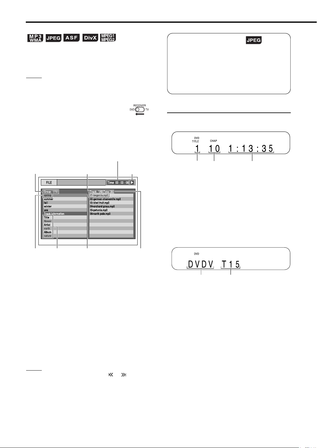
This part explains the operation with displays of an
MP3 disc as examples.
For a JPEG disc, read “track” as “file”.
NOTE
• When files of different types are recorded on a disc,
A
select the file type to be played back. (
” on page 39)
TYPE
“FILE
Slide-show playback
• In step 6, for a JPEG disc, when 3 (play) is
pressed, files will be continuously played
back from the selected file (slide-show
playback), and when ENTER is pressed, only
a selected file will be played back.
• Display time for a file in slide-show playback
is about 3 seconds.
1 Slide the remote control
mode selector to DVD.
2 Load a disc.
Elapsed
playback time of
the current track
(MP3/WMA/ASF
disc only)
Playback
status
Number of the
total tracks (files)
recorded on the
loaded disc
Numbers of the
current group
and total groups
recorded on the
loaded disc
Current
group
Tag
information
(MP3/WMA
disc only)
Numbers of the
current track
(file) and total
tracks (files)
included in the
current group
Current
track (file)
3 Press 5// (cursor) to select a
group.
4 Press 3 (cursor) to move to the
track list.
• Press 2 (cursor) to go back to the group
list.
5 Press 5// (cursor) to select a
track.
6 Press 3 (play) or ENTER.
Display window on the DVD player
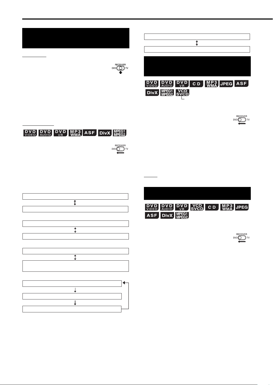
■ DVD VIDEO/DVD AUDIO/DVD VR
When a disc is played back
Title/group/
original
program/play
list number
• When a DVD AUDIO is played back, “GR” and
“TR” are displayed instead of “TITLE” and
“CHAP”.
• When a DVD VR is played back, “VR” is
displayed and “PG” (original program) or “PL”
(play list) is displayed instead of “TITLE”.
• If “BONUS” or “B.S.P.” is displayed during DVD
AUDIO playback, refer to pages 34 and 35.
When a disc is stopped
• When a DVD AUDIO is loaded; “DVDA” is
displayed instead of “DVDV”, and the total
numbers of groups and the tracks are displayed
instead of the total numbers of the titles.
• When a DVD VR is loaded; “VR” is displayed
instead of “DVDV”, the total number of original
programs or the play lists is displayed instead of
the total number of titles, and “DVD VR” is
displayed instead of “DVD”.
Chapter/
track
number
Disc type Total number of titles
Elapsed playback time
NOTE
• You can also use GROUP/TITLE or in step 3
and
PREVIOUS 4 or NEXT ¢ in st ep 5 . In t his
case, you can skip step 4.
• The number buttons can also be used in step 5. In
this case, you can skip steps 4 and 6. (Refer to
A
“Using the number buttons”. (
page 15))
21
Page 27

For the locations of the remote
control buttons, refer to page 20.
■ VCD/SVCD
When a disc is played back
Track number
• PBC (Play Back Control) is a signal recorded in
a VCD (version 2.0) for controlling playback. You
can enjoy interactive software or software with a
search function using a menu screen recorded in
a PBC compatible VCD. To play back a disc
without the PBC function, follow the instructions
below.
• Specify the track number using the number
buttons when the disc is stopped. Refer to
“Using the number buttons” (A page 15).
• Specify the track number using PREVIOUS
4 or NEXT ¢ when the disc is stopped,
and then press 3 (play).
• Press RETURN to go back to the upper layer
during PBC playback of a VCD or SVCD.
When a disc is stopped
Disc type
• When the PBC function is activated, the display
below appears after the display above is
displayed for a short time.
Total
number of
tracks
Total playback time
■ MP3/WMA/ASF/DivX/MPEG1/MPEG2 disc
When a disc is played back
Group
number
• When a WMA disc is played back, “WMA” is
displayed instead of “MP3”.
• When an ASF/DivX/MPEG1/MPEG2 disc is
played back, no disc type indicator is displayed.
When a disc is stopped
Disc type
• When a WMA disc is loaded, “WMA” is displayed
instead of “MP3” in the upper indicator and the
lower display.
• When an ASF disc is loaded; “MP3” disappears
in the upper indicator, and “ASF” is displayed
instead of “MP3” in the lower display.
• When a DivX disc is loaded; “MP3” disappears
in the upper indicator, and “DivX” is displayed
instead of “MP3” in the lower display.
number
Group number
Elapsed playback timeTrack
Track
number
■ JPEG disc
When a disc is played back or stopped
Playing back DVDs/CDs
■ CD
When a disc is played back
When a disc is stopped
Total playback timeDisc type Total
number of
tracks
File numberGroup number
Elapsed playback timeTrack number
22
Page 28
Basic operations of the DVD player (continued)
Changing the display in the display window
Receiver
■ ASF/DivX/MPEG1/MPEG2 disc
Normal display (as shown on page 22)
File type/group number/track number
1
Slide the remote control
mode selector to
RECEIVER.
2 Press DISPLAY repeatedly.
• Each time you press DISPLAY, the display
toggles between the current source (DVD,
FM, AM, AUX-DIGITAL or AUX) and the
clock.
DVD player
1 Slide the remote control
mode selector to DVD.
2 Press DISPLAY repeatedly
during playback.
• Each time you press DISPLAY, the display
changes.
7 DVD VIDEO
Normal display (as shown on page 21)
Disc type/title number/chapter number
7 DVD AUDIO
Normal display (as shown on page 21)
Selecting a chapter/track using the number buttons
(PBC off)
7 When a disc is played back
1 Slide the remote control
mode selector to DVD.
2 Use the number buttons to
select the chapter number or
track number.
• Refer to “Using the number buttons”
(A page 15).
NOTE
• You cannot use this function for some discs.
Stopping playback
7 When a disc is played back
Disc type/group number/track number
7 DVD VR
Normal display (as shown on page 21)
Disc type/original program (play list) number/
chapter number
7 MP3/WMA disc
Normal display (as shown on page 22)
File type/group number/track number
Text*
* When text, such as a file name, has been recorded in
the loaded MP3/WMA disc, the text appears and scrolls
in the display window on the DVD player.
23
1 Slide the remote control
mode selector to DVD.
2 Press 7.
Page 29

For the locations of the remote
control buttons, refer to page 20.
Pausing playback
7 When a disc is played back
1 Slide the remote control
mode selector to DVD.
2 Press 8.
• To return to normal playback, press 3
(play).
Advancing the picture frame by frame
(only for moving image)
7 When a disc is paused
1 Slide the remote control
mode selector to DVD.
2 Press 8 repeatedly.
Fast reverse/fast forward search
7 When a disc is played back
1 Slide the remote control
mode selector to DVD.
Playing back DVDs/CDs
There are two methods in step 2.
2 Press 1 or ¡.
• Each time you press the button, the speed
increases. To restore the normal speed,
press 3 (play).
Hold down PREVIOUS 4 or
NEXT¢.
• Fast reverse/fast forward search can be used
only while the button is pressed.
NOTE
• For some discs, sound is intermittent or no sound will
be produced during fast reverse/fast forward search.
• The selectable speeds and displays vary by the disc
type.
NOW READING
REGION CODE
ERROR!
NO DISC
OPEN
CLOSE
CANNOT PLAY THIS
DISC
Messages displayed on the TV when the power is turned on
The following messages appear depending on the status of the DVD player.
Appears when the DVD player is reading the disc information. Wait for a while.
Appears when the Region Code of the DVD does not match the code the DVD
player supports. (A page 47)
Appears when no disc is loaded.
Appears when the disc tray is opening.
Appears when the disc tray is closing.
Appears when an unplayable disc is attempted to be played back.
24
Page 30
Basic operations of the DVD player (continued)
Playing back from a position 10 seconds before (One touch replay)
7 When a disc is played back
1 Slide the remote control
mode selector to DVD.
2 Press ONE TOUCH REPLAY.
NOTE
• This operation may not be used for some discs.
• You cannot go back to the previous title.
Slow motion playback
(only for moving image)
7 When a disc is paused
1 Slide the remote control
mode selector to DVD.
2 Press SLOW or SLOW .
• Each time you press the button, the speed
increases.
• Press 8 to pause playback, and press
(play)
to return to normal playback.
NOTE
• No sound will be produced.
• The picture motion in the reverse direction may not
be smooth.
• For a VCD, SVCD or DVD VR, slow motion
playback can be used in the forward direction only.
3
Skipping to the beginning of a chapter/ track/file
(PBC off)
7 When a disc is played back
1 Slide the remote control
mode selector to DVD.
2 Press PREVIOUS 4 or NEXT
¢.
• Each time you press the button, the
playback position skips to the beginning of
the previous or next chapter/track/file.
• Press PREVIOUS 4
the beginning of the chapter or track
currently being played back (except for a
JPEG disc).
•Press GROUP/TITLE or to select the
title or group.
• During playback of an MP3/WMA/JPEG/
ASF/DivX disc, press NEXT ¢ or /
(cursor) to play back the next file, or press
PREVIOUS 4
the previous file.
NOTE
•
You can use this function
except for a DVD VIDEO. You can use 5 or /
(cursor) to skip to the beginning of a track while you
are viewing the TV screen.
You cannot use this function
•
once to skip back to
or 5 (cursor) to play back
while the disc is stopped
for some discs.
25
Guide icons displayed on the TV screen (on-screen guide)
Play
Pause
Fast reverse/fast forward search
Slow motion playback (reverse/
forward directions)
Containing multi-view angles
(A page 33)
Containing multi-audio languages
(A page 32)
Containing multi-subtitle languages
(A page 32)
The disc cannot accept the operation you
have attempted.
Page 31

For the locations of the remote
control buttons, refer to page 20.
Skipping at about 5 minute intervals
You can skip within a file at about 5 minute
intervals.
This is useful especially when you want to skip
within a long file.
7 When a disc is played back
1 Slide the remote control
mode selector to DVD.
2 Press 2 or 3 (cursor).
• Each time you press the button, the
playback position skips to the beginning of
the previous or next interval. Each interval
is about 5 minutes.
NOTE
• Intervals are automatically assigned from the
beginning of a file.
• You can use this function only within the same file.
You cannot use this function
•
for some discs.
Resuming playback
When playback is stopped in the middle, playback
can be started from the stopped position.
Temporarily stopping playback
7 When a disc is played back
1 Slide the remote control
mode selector to DVD.
2 Follow any of the operations
below.
Press 7 once.
Press F AUDIO to turn off the power of the
receiver.
Press F DVD to turn off the power of the DVD
player.
Change the source to FM/AM or AUX.
*1 “RESUME” will be displayed. If 7 is pressed
again at this time, “
the stored information will be cleared.
*2 After playback is stopped, even if the receiver
or the DVD player is turned off by pressing
F AUDIO or F DVD, the position where
playback has been stopped will be stored.
*1 *2
*2
RESUME” will disappear and
Playing back DVDs/CDs
Starting playback from the stored position
1 Slide the remote control
mode selector to DVD.
2 Press 3 (play).
NOTE
• This function does not work in program playback or
random playback.
• The position where playback starts again may be a
little different from the stopped position.
• When the menu screen is displayed, the resume
playback function may not work.
• The audio language, the subtitle language and the
angle at that time are stored together with the
stopped position.
• The stored position will be cleared if the disc tray is
opened.
• The resume playback function is activated as the
initial setting. You can disable the resume playback
A
function. (
“RESUME” on page 39)
26
Page 32

12/03/04
/09/
Basic operations of the DVD player (continued)
Selecting a track from the menu screen
(PBC off)
7 When a disc is stopped or played back
■ Original program
No Date Ch Time Title
12/03/04 12:15L 1
1
12/09/04
L 1
04
2 12
L 1
3 12/18/04 08:17
L 1
4 12/20/04 07:47
L 1
5 12/25/04 19:38 Mr. Lawrence
L 1
6 12/28/04 14:20
For the locations of the remote
control buttons, refer to
La fleur
23:05
The last struggle
free flyer
BOOM!
Satisfy U
page 20
.
1 Slide the remote control
mode selector to DVD.
2 Press MENU/PL or TOP MENU/
PG.
• The menu screen will be displayed.
•Only TOP MENU/PG can be used for DVD
AUDIOs.
3 Press 5///2/3 (cursor) (only
for a DVD VIDEO or DVD AUDIO)
or the number buttons to select
the desired track.
• Refer to “Using the number buttons”
(A page 15).
• When the menu screen has a couple of
pages, press PREVIOUS 4 or NEXT
to change the page (only for a VCD
¢
and SVCD).
4 Press ENTER.
NOTE
• You cannot use this function for a disc without a
menu screen.
• Playback may start for some discs without pressing
ENTER.
7 When a disc is stopped or played back
1 Slide the remote control
mode selector to DVD.
Title name
Starting time for the title
recording
Channel information
Recording date
■ Play list
No Date Chap Length Title
1 12/03/04 2 0:23:24 Nebula G.
2 12/15/04 4 1:04:39
3 12/24/04 13 0:41:26
4 12/27/04 17 0:09:08
Recording
date
Number of chapters
included in the title
CDJ
Secret Garden
S. Walker
Total playback time for
the title
• The play list will not appear when a play list
has not been recorded to the disc.
3 Press 5// (cursor) to select the
desired title.
4 Press ENTER.
• When you have selected the original
program by pressing TOP MENU/PG in
step 2, playback will start from the selected
title to the following titles.
• When you have selected the play list by
pressing MENU/PL in step 2, only the
selected title will be played back.
2 Press TOP MENU/PG to display
the original program or press
MENU/PL to display the play
list.
27
Page 33

Convenient functions of the DVD player
GROUP/
TITLE
/
PREVIOUS
4
ON
SCREEN
AUDIO
VFP
PAGE
ZOOM
PLAY
MODE
REPEAT
CLOCK/
TIMER
Remote control
mode selector
F DVD
3 (play)
5///2/3
(cursor)/
ENTER
SUBTITLE
ANGLE
Number
buttons
3D PHONIC
CANCEL
Playing back a DVD/CD in the desired order (Program playback)
You can program a maximum of 99 tracks or
chapters. The same track or chapter can be
programmed more than once.
7 When a disc is stopped
1 Slide the remote control
mode selector to DVD.
2 Press PLAY MODE repeatedly
to display “PROGRAM” in the
display window on the DVD
player.
Example:
Display on the DVD player for a DVD VIDEO
Playing back DVDs/CDs
DVD player
Locking DVD/CD ejection
You can lock the disc tray to prevent the disc from
being ejected.
Setting
Turn off the DVD player. And while
holding down 7 on the DVD player,
press 0 on the DVD player.
• “LOCKED” appears in the display window on the
DVD player.
Releasing
Follow the same instructions as
those for setting.
• “UNLOCKED” appears in the display window on
the DVD player.
Example:
TV screen for a DVD VIDEO
(Continued on the next page)
(Program screen)
28
Page 34

Convenient functions of the DVD player (continued)
3 Press the number buttons to
program chapters/tracks.
• Refer to “Using the number buttons”
(A page 15).
■ Display on the DVD player for DVD VIDEO
• Select a title number, and then a chapter
number.
Title indicator
Title number Chapter number Program number
■ Display on the DVD player for DVD AUDIO/
MP3/WMA disc
• Select a group number, and then a track
number.
Group
indicator
Group
number
■
Display on the DVD player for VCD/SVCD/CD
• Select a track number.
• As you finish the track selection, the total
time for the program playback will be
displayed.
Track indicator
Chapter indicator
Track indicator
Chapter
number
Program number
• Before selecting a bonus group of a DVD
AUDIO, cancel the “BONUS” display as
explained in “Playing back the bonus group”
on page 34.
• When you try to enter more than 99
chapters or tracks, “MEMORY FULL”
appears.
• In the case of a VCD, SVCD or CD, when
the total playback time reaches 9 hours 59
minutes 59 seconds, “--:--” will be displayed
in the display window on the DVD player.
NOTE
• Only for a DVD VIDEO, DVD AUDIO, MP3, WMA
disc, if you press ENTER instead of specifying a
track/chapter number, “ALL” is displayed and all of
the tracks/chapters included in the selected group/
title are programmed.
4 Press 3 (play).
• To return to normal playback, press PLAY
.
.
MODE repeatedly to turn off “PRGM” (the
upper indicator) in the display window on
the DVD player while the disc is stopped.
The program content will not be erased.
• The following operations erase the program
content.
• Hold down CANCEL until “ALL CLEAR!”
appears in the display window while the
program screen is displayed on the TV
screen (if CANCEL is pressed and
released quickly, programs will be erased
one by one).
• Open the disc tray.
• Turn off the power.
(Only when the setting save function
(A page 31) is not being used)
29
Track number Program number
Example:
TV screen for a DVD VIDEO
(Program screen)
Page 35
For the locations of the remote
control buttons, refer to page 28.
Playing back a DVD/CD in a random order (Random playback)
7 When a disc is stopped
1 Slide the remote control
mode selector to DVD.
2 Press PLAY MODE repeatedly
to display “RANDOM” in the
display window on the DVD
player.
• “RANDOM” will also be displayed on the TV
screen.
3 Press 3 (play).
• The same chapter or track will not be
played back twice.
• To return to normal playback, press PLAY
MODE repeatedly to turn off “RND” (the
upper indicator) in the display window on
the DVD player while the disc is stopped.
• The following operations also cancel
random playback.
• Open the disc tray.
• Turn off the power.
(Only when the setting save function
(A page 31) is not being used)
• The previous track will not be returned to
even if PREVIOUS 4 is pressed
repeatedly during random playback.
(Playback will be returned to the beginning
of the current chapter or track.)
NOTE
• You cannot use the random playback function for
some DVD VIDEOs.
Playing back a DVD/CD repeatedly (Repeat playback)
(PBC off)
7 When a disc is played back
1 Slide the remote control
mode selector to DVD.
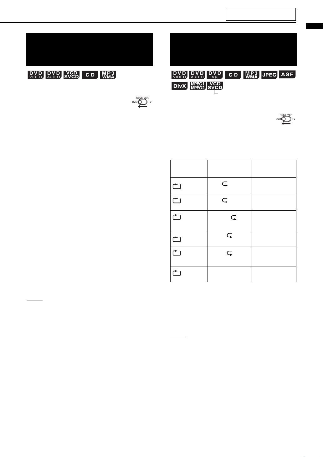
2 Press REPEAT.
• Each time you press the button, the repeat
mode changes.
Display on the
TV screen
TITLE
ALL
or REPEAT ALL
GROUP
or REPEAT
GROUP
CHAP
TRACK
or REPEAT
TRACK
OFF
or no display
*1 Repeats the whole program during program playback.
*2 For a DVD VR, “PG” is displayed during original
program playback, and “PL” is displayed during play
list playback.
*3 Repeats the current original program or the current
play list for a DVD VR.
*4
“STEP” is displayed during program/random playback.
Display in the display
window on the DVD
REPEAT TITLE
*2
REPEAT GROUP
*4
REPEAT CHAP
*4
REPEAT TRACK
REPEAT OFF Repeat off
player
ALL
ALL
REPEAT ALL
GR
Usage for the repeat
Repeats the current
title.
Repeats the whole
*1
.
disc
Repeats the current
*2
*4
*4
*3
group
.
Repeats the current
chapter.
Repeats the current
track.
mode
Playing back DVDs/CDs
NOTE
• The repeat playback can also be set on the menu
A
“Playing back a specified part repeatedly
bar. (
(A-B repeat playback)” on page 31)
• For a DVD VIDEO, DVD AUDIO and DVD VR, if the
source is switched to FM/AM or AUX, the repeat
mode will be cancelled.
• The repeat mode will be automatically cancelled if
there is a file that cannot be played back
A
page 47).
(
30
Page 36

Convenient functions of the DVD player (continued)
Playing back a specified part repeatedly (A-B repeat playback)
(PBC off)
You can play back the desired part repeatedly by
specifying a start point (A) and an end point (B).
7 When a disc is played back
1 Slide the remote control
mode selector to DVD.
2 Press ON SCREEN twice.
• The menu bar (A page 36) will be
displayed.
3 Press 2/3 (cursor) to select
OFF
.
4 Press ENTER.
5 Press 5// (cursor) to display
.
• Other repeat modes can be selected in this
step. For other repeat modes, refer to
“Playing back a DVD/CD repeatedly
(Repeat playback)” (A page 30).
Saving the playback settings for next time
You can save the settings for program playback,
random playback or repeat playback so that the
settings are activated even after the DVD player is
turned off and then on again.
Combining this function with the playback timer
(A page 43), you can make a variety of playback
settings.
1 Slide the remote control
mode selector to DVD.
2 Press CLOCK/TIMER.
• The current settings for program/random/
repeat playback will be stored.
Display on the DVD player
NOTE
• To cancel the setting save function, press CLOCK/
TIMER again.
6 Press ENTER at the start point
of the part to be repeated
(specifying point A).
• The icon on the menu bar will be .
A-
7 Press ENTER at the end point of
the part to be repeated
(specifying point B).
• The icon on the menu bar will be .
will appear in the display window on the
DVD player and the part between points A
and B will be played back repeatedly.
• A-B repeat playback can be cancelled by
following the operations below.
• Press 7.
• Select and press ENTER twice.
(Select .)
NOTE
• You can use A-B repeat playback only within the
same title or track.
• You cannot use A-B repeat playback during program
playback, random playback or repeat playback.
• You cannot use the A-B repeat playback function for
some DVD VIDEOs.
A-B
OFF
A-B
• Opening the disc tray also cancels the setting save
function.
• Resume playback does not work when the settings
for program/random/repeat playback are saved. For
example, if the program playback settings are saved
F DVD is pressed to turn off the DVD player
and
during playback, pressing
DVD player again and pressing
playback of the first programmed track/chapter.
Conversely, if the program playback settings are not
saved and 3 (play) is pressed after the DVD player
is turned on, the resume playback function operates
and playback starts from the point where the disc
was stopped.
• For a JPEG/ASF/DivX/MPEG1/MPEG2 disc, you
can use the setting save function for repeat
playback only.
F DVD to turn on the
3 (play) starts
31
Page 37

For the locations of the remote
control buttons, refer to page 28.
Selecting the subtitles
(only for moving image)
This part explains the operation with displays of a
DVD VIDEO as examples.
You can use discs of other types in almost the
same manner.
7 When a disc contains subtitles and is played
back
1 Slide the remote control
mode selector to DVD.
2 Press SUBTITLE.
Example:
• Each time you press the button, the subtitle
will toggle between on and off.
TV screen
3 Press 5// (cursor) to select a
subtitle language.
4 Press ENTER.
• The subtitle language setting will change
automatically in a few seconds even if
ENTER is not pressed.
NOTE
• You can use this function with the menu bar
A
page 36).
(
• For a language code such as “AA”, refer to
“Language codes” (
A
page 51).
Selecting the audio language
7 When a disc contains multiple audio
languages and is played back
1 Slide the remote control
mode selector to DVD.
2 Press AUDIO.
Example:
• Each time you press the button, the audio
language will be changed. Also, the audio
language can be changed by pressing 5//
(cursor).
TV screen
3 Press ENTER.
• The audio language setting will change
automatically in a few seconds even if
ENTER is not pressed.
NOTE
• You can use this function with the menu bar
A
page 36).
(
• For a language code such as “AA”, refer to
“Language codes” (
• “ST”, “L” and “R” displayed when playing back a
VCD, SVCD or DVD VR respectively represent
“Stereo”, “Left sound” and “Right sound”.
• For a DivX disc, only the number of the language is
displayed on the TV screen.
A
page 51).
Playing back DVDs/CDs
32
Page 38

Convenient functions of the DVD player (continued)
Selecting the view angle
(only for moving image)
7 When a scene containing multi-view angles is
played back
1 Slide the remote control
mode selector to DVD.
2 Press ANGLE.
Example:
• Each time you press the button, the angle
will be changed. Also, the angle can be
changed by pressing 5// (cursor).
TV screen
TV screen
3 Press ENTER.
• The angle setting will change automatically
in a few seconds even if ENTER is not
pressed.
NOTE
• You can use this function with the menu bar
A
page 36).
(
Magnifying the picture (ZOOM)
(only for moving image)
7 When a disc is played back or paused
1 Slide the remote control
mode selector to DVD.
2 Press ZOOM.
• Each time you press the button, the picture
magnification will be changed.
3 Select the portion you want to
magnify by using 5///2/3
(cursor).
• To return to normal playback, select “ZOOM
OFF” in step 2.
NOTE
• For a JPEG disc, you cannot change the picture
magnification during slide-show playback.
• During ASF playback, there may be a case where
5///2/3 (cursor) does not work in step 3.
33
Page 39

For the locations of the remote
control buttons, refer to page 28.
Adjusting the picture quality (VFP)
7 When a disc is played back or paused
1 Slide the remote control
mode selector to DVD.
2 Press VFP.
• The current setting will appear on the TV
screen.
• The “GAMMA” setting adjusts the
brightness of neutral tints while maintaining
the brightness of dark and bright portions.
• The “SHARPNESS” setting adjusts the
screen sharpness.
NOTE
• If no operation is made for several seconds during
the procedure, the settings made so far will be
automatically stored.
• “VFP” stands for “Video Fine Processor”.
Playing back the bonus group
There are some DVD AUDIOs with a special
group, called “bonus group”, recorded.
NOTE
• You can use this function when “BONUS” lights up
in the display window on the DVD player.
7 When a disc is played back
1 Slide the remote control
mode selector to DVD.
2 Press GROUP/TITLE
repeatedly to select a bonus
group.
• “KEY_ _ _ _” appears on the TV screen,
and in the display window on the
player
.
DVD
Playing back DVDs/CDs
3 Press 2/3 (cursor) to select
VFP mode.
• Selecting “NORMAL” is suitable for normal
usage, and selecting “CINEMA” is suitable
for a dark room. When selecting “NORMAL”
or “CINEMA”, proceed to step 8.
• Selecting “USER1” or “USER2” enables
you to make detailed adjustment in step 4
and the later steps.
4 Press5// (cursor) to select an
item to be adjusted.
5 Press ENTER.
Example:
GAMMA
TV screen
6 Press 5// (cursor) to change
the value.
7 Press ENTER.
• To adjust other items, go back to step 4.
8 Press VFP.
3 Press the number buttons to
enter the pin code (4 digits).
• The method of obtaining a pin code differs
depending on the disc.
4 Press ENTER.
• When the correct pin code is entered,
“BONUS” disappears and the playback of
the bonus group starts.
• If an incorrect pin code is entered, try
entering the correct pin code again.
34
Page 40
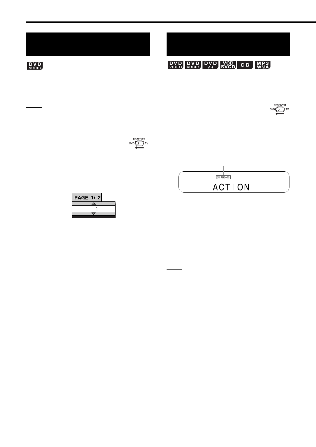
Convenient functions of the DVD player (continued)
Browsable still pictures (B.S.P.)
Some DVD AUDIOs may have pictures called
B.S.P. (Browsable Still Pictures). The pictures can
be viewed as if you are turning pages.
NOTE
• You can use this function when “B.S.P.” lights up in
the display window on the DVD player.
7 When a disc is played back
1 Slide the remote control
mode selector to DVD.
2 Press PAGE.
• Each time you press the button, the still
picture will be changed. You can also switch
the picture using 5// (cursor).
Example:
TV screen
3 Press ENTER.
• The picture setting will change
automatically in a few seconds even if
ENTER is not pressed.
NOTE
• You can use this function with the menu bar
(
A
page 36).
Creating realistic sound (3D PHONIC)
The two speakers produce an effect resembling
surround-sound.
7 When a disc is played back
1 Slide the remote control
mode selector to DVD.
2 Press 3D PHONIC repeatedly to
select the desired sound effect.
Example:
Display on the DVD player
This indicator lights up when 3D PHONIC is
activated.
• “ACTION” is suitable for action movies,
sport programs or other lively programs.
• Select “DRAMA” to enjoy a sound effect
with a relaxing, natural atmosphere.
• Select “THEATER” to enjoy a sound effect
as if you were watching the movie in a
theater.
• Select “3D PHONIC OFF” to cancel 3D
PHONIC. (initial setting)
NOTE
• 3D PHONIC is effective for both the speakers and
headphones.
• If noise is produced or sound is distorted, select “3D
PHONIC OFF ”.
• When 3D PHONIC is activated, analog playback is
selected automatically, and “DVD-ANALOG” is
displayed in the display window on the receiver.
Canceling 3D PHONIC returns to “DVD-DIGITAL”
automatically. When a DVD AUDIO is played back,
signals are converted into analog signals regardless
of whether 3D PHONIC is activated or canceled.
• You cannot use this function for some DVD
AUDIOs.
• When 3D PHONIC is activated, the CC
CONVERTER function will be cancelled
automatically. (
• For an ASF/DivX/MPEG1/MPEG2 disc, 3D
PHONIC does not work and creates no sound effect
even when “ACTION”, “DRAMA” or “THEATER” is
displayed.
A
page 17)
35
Page 41

Using the status bar and the menu bar
For the locations of the remote
control buttons, refer to page 28.
Information displayed on the status bar
DVD VIDEO/DVD AUDIO/DVD VR (the example
below is for a DVD VIDEO)
7 When a disc is played back
1 Slide the remote control
mode selector to DVD.
2 Press ON SCREEN twice.
• “ON SCREEN” will appear in the display
window on the DVD player. The status bar
and the menu bar will appear on the TV
screen.
Example:
When a DVD VIDEO is loaded
Status bar
Menu bar
3 Press 2/3 (cursor) to select an
item to be operated.
4 Press ENTER.
• The selected function can be set. For the
setting content, refer to “Function list”.
(A page 37)
• The currently active function is shown in
blue.
• To turn off the menu bar, press ON
SCREEN.
Sound
signal type
(DVD VIDEO)
Current title number
(DVD AUDIO)
Current group number
(DVD VR)
Current original
program number (PG)/
current play list
number (PL)
VCD/SVCD/CD/ASF/DivX/MPEG1/MPEG2 disc
(the example below is for a CD)
Playback mode status
NOTE
• The playback status has the same meaning of the
mark on the on-screen guide (
(DVD VIDEO/DVD VR)
Current chapter number
(DVD AUDIO)
Current track number
(VCD/SVCD/CD)
Current track number
(ASF/DivX/MPEG1/MPEG2 disc)
Repeat mode status
Playback
Time
status
0:25:58
Time Playback
status
A
page 25).
Playing back DVDs/CDs
36
Page 42
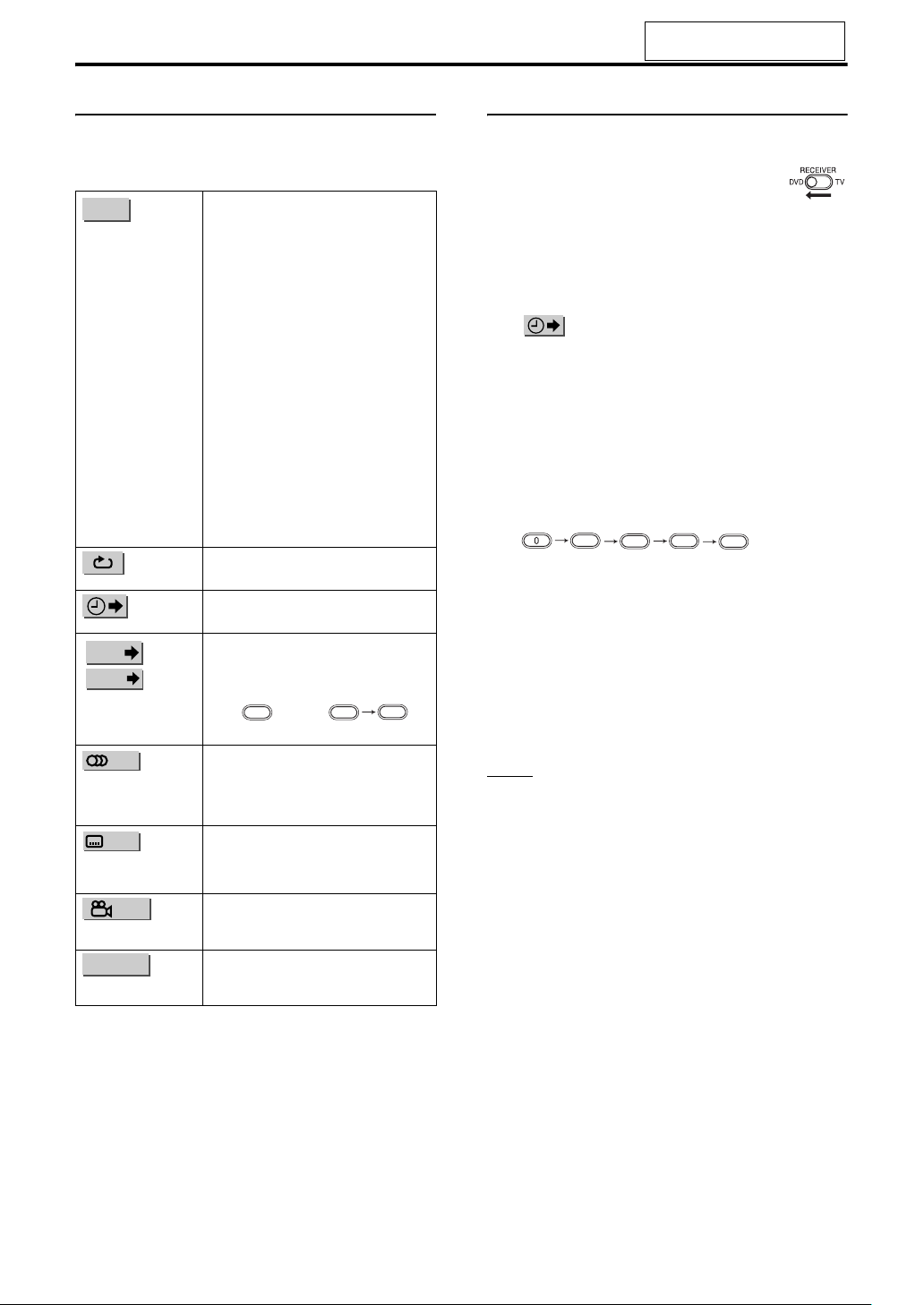
Convenient functions of the DVD player (continued)
For the locations of the remote
control buttons, refer to page 28.
Function list
For functions with no description of the operation,
press 5// (cursor) to select and press ENTER to
determine the function.
TIME
Time display
selection
Repeat mode
Time search
CHAP
.
/
TRACK
Chapter search
(DVD VIDEO/DVD
VR)/Track search
(DVD AUDIO)
Audio language/
Audio (DVD VIDEO/
DVD AUDIO/VCD/
SVCD)
Subtitle language
(DVD VIDEO/DVD
VR/SVCD)
3
1/
View angle (DVD
VIDEO/DVD AUDIO)
PAGE -/-
Page switch (DVD
AUDIO)
Changes the time information in the
display window on the DVD player and
the status bar. Each time ENTER is
pressed, the display will be changed.
DVD VIDEO/DVD AUDIO (operating
during playback)
TOTAL: Elapsed playback time of the
current title/group.
T.REM: Remaining time of the current
title/group.
TIME : Elapsed playback time of the
current chapter/track.
REM : Remaining time of the current
chapter/track.
DVD VR (operating during playback)
TOTAL: Elapsed playback time of the
current title/group.
T.REM: Remaining time of the current
title/group.
CD (operating during playback)/VCD/
SVCD
TIME : Elapsed playback time of the
current track.
REM : Remaining time of the current
track.
TOTAL: Elapsed
T.REM: Remaining time of the disc.
A page 30
A on the right
Selects a chapter/track. Press the
number buttons to input the chapter/
track number and press ENTER.
Examples:
5
5:
A page 32
A page 32
A page 33
Switches the browsable still pictures
(B.S.P.) recorded on a DVD AUDIO.
(A page 35)
disc.
playback
24:
time of the
2
4
Designating the time (Time search)
7 When a disc is played back
1 Slide the remote control
mode selector to DVD.
2 Press ON SCREEN twice.
• The menu bar will appear (A page 36).
3
Press 2/3 (cursor) to select
.
4 Press ENTER.
5 Input the time using the number
buttons (1-9, 0).
Example:
When you want to play back a DVD VIDEO
from the position of (0 hour) 23 minutes 45
seconds, press the buttons in the order:
2
• You can skip the minute and second
setting.
• If the incorrect value is input, press 2
(cursor) to delete the values and input
values again.
4
3
5
.
6 Press ENTER.
• To turn off the menu bar, press ON
SCREEN.
NOTE
• This function does not work for a DVD VIDEO with
no time information recorded.
• This function does not work during program
playback or random playback.
• For a CD, you can use this function any time.
• For a VCD or SVCD, you can use this function
during playback without the PBC function.
• Time search for a DVD VIDEO is from the beginning
of the title. Time search for a DVD AUDIO is from
the beginning of the track being played back. Time
search for a VCD, an SVCD and a CD is as follows:
• When the disc is stopped, time search is from the
beginning of the disc.
• When the disc is being played back, time search
is within the track currently being played back.
37
Page 43

Changing the initial settings with the preference screen
Basic operations
Remote control
mode selector
5///2/3
(cursor)/
ENTER
SET UP
Number
buttons
The initial settings of the DVD player can be
changed with the preference screen according to
the environment where the DVD player is used.
NOTE
• The top and bottom of the preference screen may
not be displayed on a wide TV. Adjust the picture
size on the TV.
7 When a disc is stopped or no disc is loaded
(“NO DISC” is displayed)
1 Slide the remote control
mode selector to DVD.
2 Press SET UP.
• The following screen will be displayed on
the TV.
• Proceed with operations by following the
description on the TV screen.
LANGUAGE
NOTE
• If the selected language is not recorded on the disc,
the optimum language set for the disc will be
displayed.
• For a language code such as “AA”, refer to the
“Language codes” (
Items Contents
MENU
LANGUAGE
AUDIO
LANGUAGE
SUBTITLE
ON SCREEN
LANGUAGE
A
page 51).
Selects the language for the DVD VIDEO
menu screen.
Selects the audio language for the DVD
VIDEO.
Selects the subtitle language for the DVD
VIDEO.
Selects the language displayed on the
preference screens.
Playing back DVDs/CDs
38
Page 44

Changing the initial settings with the preference screen (continued)
PICTURE
PICTURE
Items Contents ( : initial setting)
MONITOR
TYPE
PICTURE
SOURCE
SCREEN
SAVER
FILE TYPE Select an item suitable to the file type.
16 : 9:
For an ordinary wide TV.
4 : 3 LB (Letterbox)
For a TV with conventional 4:3 aspect ratio.
When a wide screen picture is input, the black
bars appear on the top and bottom of the
screen.
4 : 3 PS (Pan Scan):
For a TV with conventional 4:3 aspect ratio.
When a wide screen picture is input, the left
and right edges of the picture will not be
shown on the screen. (If the disc is not
compatible with Pan Scan, the picture will be
displayed at the Letterbox ratio.)
Select an item suitable to the video source.
:
AUTO
The video source type (a video or film) is
automatically selected.
FILM:
To view a film or video recorded with the
progressive scan method.
VIDEO:
To view a normal video.
Select the Screen Saver mode between /
OFF (Screen Saver activates when there is no
operation made for about 5 minutes since a
still picture was last displayed).
:
AUDIO
For MP3/WMA files.
STILL PICTURE:
For JPEG files.
VIDEO:
For ASF/DivX/MPEG1/MPEG2 files.
:
ON
AUDIO
Items Contents ( : initial setting)
DIGITAL
AUDIO
OUTPUT*
DOWN MIX Select the signal suitable to the equipment
D (Dynamic).
RANGE
COMPRESSION
*
When using the supplied XV-EXA10, make sure that
Select the output signal type suitable to the
equipment connected to the DIGITAL OUT
terminal (a decoder-built-in amplifier or
other digital equipment with an optical
input terminal). Refer to “List of
relationships of DIGITAL AUDIO OUTPUT
preference items and output signal”
(A page 40).
PCM ONLY
Equipment corresponding only to linear PCM.
DOLBY DIGITAL/PCM:
Dolby digital decoder or equipment having the
same function.
STREAM/PCM:
DTS/Dolby digital decoder or equipment
having the same function.
connected to the DIGITAL OUT terminal.
Set “DOWN MIX” only when “DIGITAL
AUDIO OUTPUT” is set to “PCM ONLY”.
DOLBY SURROUND:
Dolby Pro Logic decoder-built-in equipment.
STEREO
Ordinary audio equipment.
To correct the difference between high
volume and low volume when playing back
with low volume (only for a DVD recorded
with Dolby digital).
AUTO
The D. RANGE COMPRESSION function
automatically works.
ON:
The D. RANGE COMPRESSION function
always works.
:
:
:
“DIGITAL AUDIO OUTPUT” is set to “PCM ONLY”
OTHERS
Items Contents ( : initial setting)
RESUME Select /OFF. (A page 26)
ON SCREEN
GUIDE
AV
COMPULINK
MODE
DivX
REGISTRATION
ON
Select /OFF. (A page 25)
ON
When you want to control the supplied DVD
player and the connected TV or other
equipment at the same time, select a
setting according to the type of terminal on
the equipment connected to the DVD
player. (Refer to “Using the AV COMPU
LINK function” (A page 45).)
DVD1
:
When the video 3 input terminal on the TV or
the DVD input terminal is connected.
DVD2:
When the video 1 input terminal on the TV is
connected.
DVD3:
When the video 2 input terminal on the TV is
connected.
The DVD player has its own registration
code. You can confirm the registration
code, when necessary. Once you have
played back a disc in which the registration
code is recorded, the registration code of
the DVD player is overwritten for copyright
protection.
.
39
Page 45
For the locations of the remote
control buttons, refer to page 38.
List of relationships of DIGITAL AUDIO OUTPUT preference items and output signal
Playback disc
48 kHz, 16/20/24 bit
Linear PCM DVD VIDEO
96 kHz linear PCM DVD VIDEO
16/20/24 bit linear PCM DVD AUDIO*
16/20/24 bit linear PCM DVD AUDIO*
DOLBY DIGITAL DVD VIDEO/DVD
48/96/192 kHz,
44.1/88.2/176.4 kHz,
DTS DVD VIDEO/DVD AUDIO* 48 kHz, 16 bit stereo linear PCM DTS bit stream
AUDIO*
VCD/SVCD/CD
DTS CD 44.1 kHz, 16 bit linear PCM
MP3/WMA/DivX disc 32/44.1/48 kHz, 16 bit linear PCM
PCM ONLY DOLBY DIGITAL/PCM STREAM/PCM
48 kHz, 16 bit stereo linear
PCM
44.1 kHz, 16 bit stereo linear PCM/48 kHz, 16 bit linear PCM
DIGITAL AUDIO OUTPUT preference
48 kHz, 16 bit stereo linear PCM
48 kHz, 16 bit stereo linear PCM
44.1 kHz, 16 bit stereo linear PCM
DOLBY DIGITAL bit stream
DTS bit stream
NOTE
* Copyright-protected DVD AUDIOs do not output signals.
• Among DVD VIDEOs without copyright protection, there may be some DVD VIDEOs that output a 20 or 24 bit
signal through the digital audio output terminals.
• To produce the sound from the loaded disc in the DVD player, select “PCM ONLY”. Otherwise the receiver does
not detect the signal and no sound is produced. (The initial setting is “PCM ONLY”.)
Playing back DVDs/CDs
40
Page 46
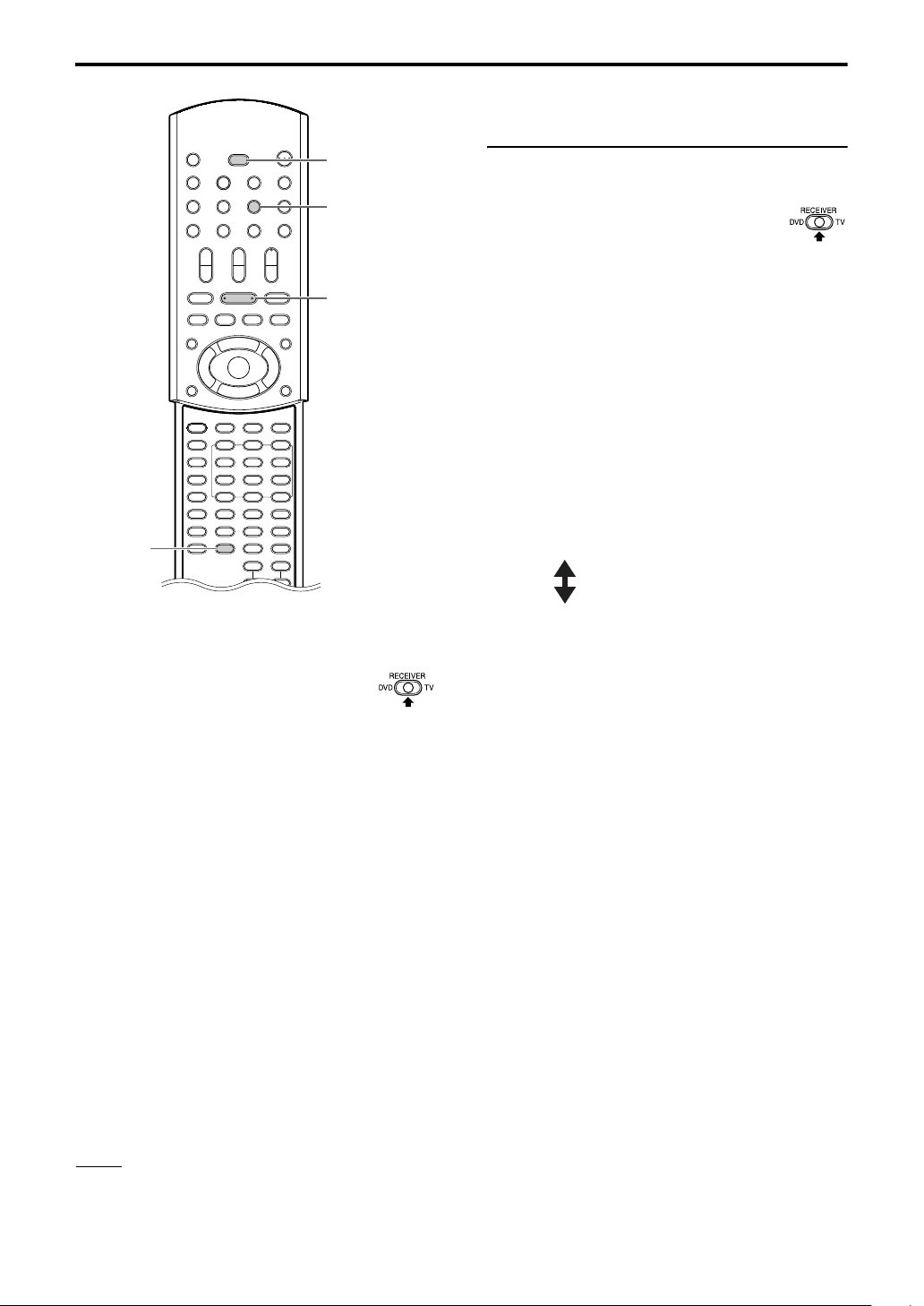
Listening to the sound of other audio equipment
Listening to the sound of other audio equipment
Adjust the sound input level of the audio
equipment
Remote control
mode selector
AUX
You can adjust the sound input level of audio
equipment connected to the AUX terminals.
1 Slide the remote control
mode selector to
RECEIVER.
3
(play)
2 Press AUX to select “AUX”.
• Each time you press AUX, the display on
the receiver toggles between
“AUX-DIGITAL” and “AUX”.
• The source changes to the signal from the
AUX terminals.
3 Hold down MEMORY until the
input level is displayed.
• Each time you hold down the button, the
input level switches as follows:
MEMORY
LEVEL1 STORED: For normal use.
(initial setting)
Connect the other audio equipment to this system
in advance (A page 12).
1 Slide the remote control
mode selector to
RECEIVER.
2 Press AUX to select
“AUX-DIGITAL” or “AUX”.
• Each time you press AUX, the display on
the receiver toggles between
“AUX-DIGITAL” and “AUX”.
• The source changes to the signal from the
AUX terminals.
• You can also use SOURCE SELECT on the
receiver to select the signal from the AUX
terminals as the sound source.
3 Begin playback on the other
audio equipment.
• For details on beginning playback, refer to
the manual of the connected equipment.
4 Adjust the volume and the
sound quality of the system
(A page 16).
LEVEL2 STORED: To correct distorted
sound caused by an
extremely high input
level from other
equipment.
NOTE
• When no equipment is connected to the DIGITAL IN
AUX terminal or the power of the connected
equipment is off, after “AUX-DIGITAL” is selected,
the display changes to “AUX-D UNLOCK”.
41
Page 47
Timer
Timer
SET
CLOCK/
TIMER
Remote control
mode selector
F AUDIO
2/3
(cursor)
Number
buttons
SLEEP
CANCEL
Using the sleep timer
When the time you specify elapses, the system will
be turned off automatically.
1 Slide the remote control
mode selector to
RECEIVER.
2 Press SLEEP.
• Each time you press the button, the time
indicated in the display window on the
receiver changes (in minutes).
Example:
Display on the receiver when the sleep timer is set
to 60 minutes
The sleep timer will be automatically set in a few
seconds, and the indication will disappear.
NOTE
When the sleep timer is set, the display window
darkens automatically.
Listening to the sound of other audio equipment/Timer
Changing the time
Select the time again by pressing
SLEEP repeatedly in step 2.
Confirming the time
Press SLEEP once in step 2 while
the sleep timer is set.
Canceling the sleep timer
Press SLEEP repeatedly in step 2
until “SLEEP OFF” appears.
NOTE
• The sleep timer will also be cancelled when the
power is turned off.
42
Page 48

Timer (continued)
Using the playback timer
Set the clock beforehand. (A page 15)
1 Slide the remote control
mode selector to
RECEIVER.
2 Press CLOCK/TIMER.
Display on the receiver
• If you accidentally pressed CLOCK/TIMER
twice or more, press CLOCK/TIMER
repeatedly until the display shown above is
displayed.
3 Press SET.
4 Set the starting time and ending
time with 2, 3 (cursor), and
then press SET.
Example:
Display on the receiver when setting the
starting time to 8:45 (for U.S.A. or Canada
models)
Display on the receiver when setting the
ending time to 9:45 (for U.S.A. or Canada
models)
5 Press 2 or 3 (cursor) to select
“ONCE” or “WEEKLY”, and
then press SET.
ONCE The playback timer works once.
WEEKLY The playback timer works
weekly or every day.
6 Press 2 or 3 (cursor) to select
the desired day of the week, and
then press SET.
• Each time you press 2 or 3 (cursor), the
display changes as follows.
When “ONCE” is selected
When “WEEKLY” is selected
(The playback timer works every day.)
(The playback timer
works Monday to
Saturday.)
(The playback timer
works Monday to
Friday.)
7 Press 2 or 3 (cursor) to select
the desired sound source, and
then press SET.
• If you have selected “FM” or “AM” in this
step, press 2, 3 (cursor) or the number
buttons to select the preset number of the
radio station whose broadcast you want to
listen to (Refer to “Using the number
buttons” (A page 15)), and then press SET.
8 Press 2 or 3 (cursor) to adjust
the playback volume, and then
press SET.
• You can use the number buttons to specify
the volume.
• The settings will appear in the display
window on the receiver.
43
• Press 2 or 3 (cursor) to select the value
and press SET to set the value.
• You can use the number buttons instead of
2 or 3 (cursor). Refer to “Using the
number buttons” (A page 15).
• For U.S.A. or Canada models, the time
display on the receiver is a 12-hour clock.
• For models sold at post exchanges, the
time display on the receiver is a 24-hour
clock.
Page 49

For the locations of the remote
control buttons, refer to page 42.
9 Press F AUDIO to turn off the
receiver.
• The playback timer is available only when
the receiver is off.
This indicator lights up when the playback
timer is activated.
NOTE
• Complete the playback timer setting at least 1
minute prior to the starting time you have selected in
step 4.
• While setting the playback timer, you can return to
the previous step by pressing CANCEL or you can
stop the setting by pressing CLOCK/TIMER.
• When the playback starts, the volume gradually
increases to the selected level.
• You can make a variety of playback settings by
combining the playback timer and saving the
settings for program playback, random playback or
A
repeat playback. (
Canceling the playback timer
Press CANCEL after following
steps 1 and 2 on page 43.
page 31)
Activating the playback timer again
After following steps 1 and 2 on
page 43, press ENTER. Then press
F AUDIO to turn off the receiver.
NOTE
• When the power cord of the receiver is
disconnected from the AC outlet or the power is
interrupted, the clock and the playback timer
settings may be lost. If the settings are lost, set the
clock and playback timer again.
Confirming the playback timer settings
Press SET repeatedly after
following steps 1, 2 and 3 on
page 43.
• To return to the normal display while confirming
the settings, press CLOCK/TIMER.
Changing the playback timer settings
Set the playback timer again from
step 1 on page 43.
Timer
NOTE
• Even after you canceled the playback timer, the
setting remains stored.
44
Page 50

Using the AV COMPU LINK function
When a JVC-manufactured TV with AV COMPU
LINK II or III terminals is connected to the DVD
player using these terminals, operating either the
TV or the DVD player controls the other equipment
at the same time.
Connection and setup
NOTE
• “AV COMPU LINK” is printed for terminals on some
JVC-manufactured TVs. These terminals are no
different from the “AV COMPU LINK I/II” or “AV
COMPU LINK” terminal.
• Refer to “OTHERS” (
the “AV COMPULINK MODE” setting.
• Also refer to the manual of the TV to be connected
to the DVD player.
AV
COMPU LINK
II or III
A
page 39) for determining
DVD player (rear panel)
Operation
1 Turn on the main power of the
TV.
2 Slide the remote control
mode selector to DVD.
3 Press 0 OPEN/CLOSE.
• The disc tray ejects.
4 Place a disc.
5 Press 3 (play) or DVD.
• The power of the TV is turned on.
• The input mode on the TV changes to either
the video 1 input or the video 3 (DVD) input.
JVC-manufactured TV
Input terminal on the TV
• Connect the video 3 (DVD) input terminal on the
TV.
• If the video 3 input terminal is used for the
playback of a digital video movie, this terminal
does not work with the AV COMPU LINK
function.
Connection cord
(not supplied)
“AV COMPULINK MODE”
Video 1 DVD2
Video 2 DVD1
setting
45
Page 51

Special cautions
Notes on handling
7 Important cautions
Installation of the system
• Select a place which is level, dry and neither too hot
nor too cold; between 5°C and 35°C (between 41°F
and 95°F).
• Leave sufficient distance between the system and the
TV.
• Do not use the system in a place subject to vibration.
Power cord
• Do not handle the power cord with wet hands!
• A small amount of power is always consumed while
the power cord is connected to the wall outlet.
• When unplugging the power cord from the wall outlet,
always pull on the plug, not the power cord.
To prevent malfunctions of the system
• There are no user-serviceable parts inside. If anything
goes wrong, unplug the power cord and consult your
dealer.
• Do not insert any metallic object into the system.
• Do not use any non-standard shape disc (like a heart,
flower or credit card, etc.) available on the market,
because it may damage the system.
• Do not use a disc with tape, stickers, or paste on it,
because it may damage the system.
Label sticker
Reference
Care of the cabinet
When cleaning the system, use a soft cloth and follow the
relevant instructions on the use of chemically-coated
cloths. Do not use benzene, thinner or other organic
solvents including disinfectants. These may cause
deformation or discoloring.
Care of the disc tray
When cleaning the disc tray, gently wipe the dirt off the
surface with a soft cloth dampened with a small amount
of a neutral detergent diluted with water, preventing the
discoloration and damage to its surface.
If water gets inside the system
Turn the system off and disconnect the power cord plug
from the wall outlet, then call the store where you made
your purchase. Using the system in this condition may
cause fire or electrical shock.
7
When condensation or water drops adhere to the lens
In any of the following cases, condensation or water
drops may adhere to the lens, preventing the system
from working properly:
• Immediately after room heating starts
• When the system is installed in a steamy or damp
space
• When the system is suddenly moved from a cold place
to a warm space
In any of these cases, leave the system turned on for 1 or
2 hours before use.
Reference
Sticker
Paste
Note about copyright laws
Check the copyright laws in your country before
recording from DVDs, VCDs, SVCDs and CDs.
Recording of copyrighted material may infringe copyright
laws.
Note about copy guard system
DVDs are protected by copy guard system. When you
connect the system to your VCR directly, the copy guard
system activates and the picture may not be played back
correctly.
7 Safety precautions
Avoid moisture, water and dust
Do not place the system in moist or dusty places.
Avoid high temperatures
Do not expose the system to direct sunlight and do not
place it near a heat source.
When you are away
When away on travel or for other reasons for an extended
period of time, disconnect the power cord plug from the
wall outlet.
• Manufactured under license from Dolby Laboratories. “Dolby”, “MLP Lossless”, and the double-D symbol are
trademarks of Dolby Laboratories.
• “DTS” and “DTS 2.0+DIGITAL OUT” are registered trademarks of Digital Theater Systems, Inc.
• This product incorporates copyright protection technology that is protected by method claims of certain U.S. patents
and other intellectual property rights owned by Macrovision Corporation and other rights owners. Use of this
copyright protection technology must be authorized by Macrovision Corporation, and is intended for home and other
limited viewing uses only unless otherwise authorized by Macrovision Corporation. Reverse engineering or
disassembly is prohibited.
• “Official DivX CertifiedTM product”, “Plays DivX® 5, DivX® 4, DivX® 3, and DivX® VOD video content (in compliance
with DivX CertifiedTM technical requirements)”, “DivX, DivX Certified”, and associated logos are trademarks of
DivXNetworks, Inc. and are used under license.
46
Page 52
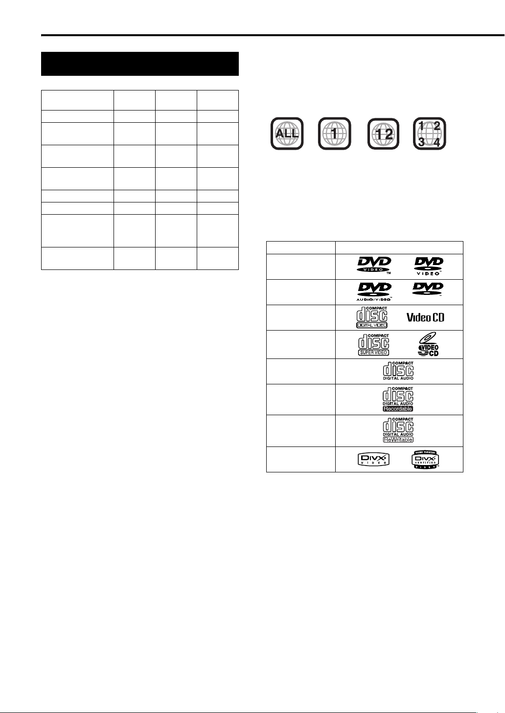
About DVDs/CDs
Playable DVD/CD types
CD-R/
CD-RW
Audio CD format
VCD/SVCD
format
MP3/WMA/
JPEG format
DVD Video
format
DVD V R fo r m a t
DivX format
Playable
Playable
Playable Playable
—
—
Playable
ASF (Advanced
Systems
Playable Playable Playable
Format)
MPEG1/MPEG2
format
• Discs should be finalized before being played back.
1 A DVD-R recorded in multi-border format is also
playable (except for dual layer discs).
2 Only when a DVD-R is compatible with CPRM
(Content Protection for Recordable Media), DVD VR
format can be used.
3 A DivX formatted DVD-ROM is also playable.
4 Among MP3/WMA/JPEG discs, only discs formatted
with a combination of Universal Disc Format and ISO
9660 (known as UDF Bridge) are playable.
Some discs may not be played back because of their disc
characteristics, recording conditions, or damage or stains
on them.
It is possible to play back finalized +R/+RW (DVD Video
Format only) discs. “DVD” lights on the front display
panel when a +R/+RW disc is loaded.
Only sounds can be played back from the following discs:
MIX-MODE CD CD-G
CD-EXTRA CD TEXT
Playable Playable Playable
1
DVD-R
DVD-RW
——
——
4
Playable
Playable Playable
Playable2Playable
Playable3Playable
Region code of DVD VIDEO
DVD VIDEO players and DVD VIDEO discs have their
own Region Code numbers. This system can play back
DVD VIDEO discs whose Region Code numbers include
the system’s Region Code, which is indicated on the rear
panel.
Examples:
4
If a DVD VIDEO with an improper Region Code
number is loaded, “REGION CODE ERROR!” appears
on the TV screen and playback cannot start.
• On some DVD VIDEOs, DVD AUDIOs, VCDs, SVCDs
or DivX discs, their actual operation may be
different from what is explained in this manual.
This is due to the disc programming and disc
structure, not a malfunction of this system.
Discs you can play back:
Disc Type Mark (Logo)
DVD VIDEO
DVD AUDIO
AUDIO
VCD
SVCD
CD
CD-R
CD-RW
DivX
47
Page 53

Discs that cannot be played back
• The following discs cannot be played back:
DVD-ROM (except for MP3/WMA/JPEG/ASF/DivX/
MPEG1/MPEG2 format), DVD-RAM, CD-ROM, CD-I
(CD-I Ready), Photo CD, SACD, etc.
Playing back these discs will generate noise and
damage the speakers.
Damaged discs and discs in an extraordinary shape
(other than a disc of 12 cm or 8 cm (4 ″ or 3 ″) in
diameter) cannot be played back.
3
3
4
16
About MP3/WMA/JPEG/ASF/DivX/MPEG1/
MPEG2 discs
Playable MP3/WMA/JPEG/ASF/DivX/MPEG1/MPEG2
discs and files
• CDs recorded in the ISO 9660 format are playable
(except CDs recorded in the “packet write” format
(UDF format)).
• CDs recorded with multiple sessions are also playable.
• Files with an extension of “.mp3”, “.wma”, “.jpg”,
“.jpeg”, “.asf”, “.divx”, “.div”, “.avi”, “.mpg” or “.mpeg”
(extensions with uppercase and lowercase letters
mixed are also acceptable) are playable.
Notes on MP3/WMA/JPEG/ASF discs and files
• A disc may not be played back, or reading it may take a
long time depending on its recording conditions or
properties.
• The time needed for reading varies with the number of
groups or tracks (files) recorded on the disc.
• If a character other than single byte English characters
is used in the file name of an MP3/WMA/JPEG/ASF
file, the track/file name will not be displayed correctly.
• The order of tracks/groups displayed on the MP3/WMA
control screen, and the order of files/groups displayed
on the JPEG control screen may be different from that
of files/folders displayed on a computer monitor
screen.
• A commercially available MP3/WMA disc may be
played back in an order different from that indicated on
the label attached to the disc.
•Playing back an MP3/WMA/JPEG/ASF disc may take
a long time. The elapsed time is not displayed until
playback starts. The elapsed time may also not be
displayed correctly.
• For an MP3/WMA file, a disc with a sampling
frequency of 44.1 kHz and transmission rate of 128
kbps is recommended.
• This system can play back a baseline JPEG file,
excluding monochromatic JPEG files.
• This system can play back JPEG data taken with a
digital camera conforming to the DCF (Design Rule for
Camera File System) standard (when a function such
as the automatic image rotation function of a digital
camera is applied, the data no longer complies with
the DCF standard, so the image may not be
displayed).
• If data has been processed, edited and restored with
computer image editing software, the data may not be
displayed.
• This system cannot play back animations such as
MOTION JPEG, still images (TIFF etc.) other than
JPEG, or image data with sound.
• The resolution of 640 x 480 pixels is recommended for
JPEG files. If a file has been recorded at a resolution
of more than 640 x 480 pixels, display may take a long
time. An image with a resolution of more than 8 192 x
7 680 pixels cannot be displayed.
• The system supports ASF files recorded with the
maximum bit rate of 384 kbps and an audio coder
decoder of G.726.
• The maximum size of the playback picture is 352 x 288
pixels (CIF).
Notes on DivX discs and files
• The system supports DivX 5.x, 4.x and 3.11.
• The system supports DivX files with a resolution of
720 x 480 pixels or less (30 fps) and 720 x 576 pixels
or less (25 fps).
• Audio stream should conform to MPEG1 Audio Layer-2
or MPEG Audio Layer-3 (MP3).
• The system does not support GMC (Global Motion
Compression).
• Files encoded in the interlaced scanning mode may
not be played back correctly.
• Playing back a DivX disc may take a long time. The
elapsed time is not displayed until playback starts. The
elapsed time may also not be displayed correctly.
Notes on MPEG1/MPEG2 discs and files
• The stream structure of MPEG1/MPEG2 discs and
files should conform to MPEG system/program stream.
• 720 x 576 pixels (25 fps)/720 x 480 pixels (30 fps) is
recommended for the highest resolution.
• This system also supports the resolutions of 352 x
576/480 x 576/352 x 288 pixels (25 fps) and 352 x 480/
480 x 480/352 x 240 pixels (30 fps).
• The profile and level should be MP@ML (Main Profile
at Main Level)/SP@ML (Simple Profile at Main Level)/
MP@LL (Main Profile at Low Level).
• Audio streams should conform to MPEG1 Audio Layer2 or MPEG2 Audio Layer-2.
Caution for DualDisc playback:
The Non-DVD side of a “DualDisc” does not comply with
the “Compact Disc Digital Audio” standard. Therefore,
the use of Non-DVD side of a DualDisc on this product
may not be recommended.
Reference
48
Page 54

About DVDs/CDs (continued)
Disc structure
DVD VIDEO/DVD VR
A DVD VIDEO consists of “titles” and each title
may be divided into “chapters”.
A DVD VR consists of “original programs” or “play
lists” and each original program/play list may be
divided into “chapters”.
.
Title 1/Original program 1/
Chapter 1 Chapter 2 Chapter 3 Chapter 1 Chapter 2
Play list 1
DVD AUDIO
A DVD AUDIO consists of “groups” and each group
may be divided into “tracks”.
Some discs include a “bonus group” that requires a
password for playback (A page 34).
Group 1 Group 2
Track 1 Track 2 Track 3 Track 1 Track 2
Title 2/Original
program 2/Play list 2
VCD/SVCD/CD
VCD, SVCD and CD consist of “tracks”.
In general, each track has its own track number.
(On some discs, each track may also be further
divided by indexes.)
Track 1 Track 2 Track 3 Track 4 Track 5
MP3/WMA/JPEG/ASF/DivX/MPEG1/MPEG2
discs
On an MP3/WMA/JPEG/ASF/DivX/MPEG1/
MPEG2 disc, each still picture (material) is
recorded as a track/file. Tracks/files are usually
grouped into a folder. Folders can also include
other folders, creating hierarchical folder layers.
This system simplifies the hierarchical construction
of a disc and manages folders by “groups”.
Group 1 Group 2
Track 1/
File 1
Track 2/
File 2
Group 3 Group 4 Group 5
This system can recognize up to 4 000 tracks/files
in a disc. Also, the system can recognize up to 150
tracks/files per group and up to 99 groups in a disc.
Since the system ignores tracks/files with numbers
exceeding 150 and groups with numbers
exceeding 99, these cannot be played back.
• If there is any type of files other than MP3/WMA/
JPEG/ASF/DivX/MPEG1/MPEG2 files in a
folder, those files are also counted in the total file
number.
49
Page 55

Troubleshooting
When you encounter a problem that seems to be a
fault, check the following points before contacting
the JVC service center:
Power source
7 Power does not come on.
• The power cord of the receiver or the DVD
player is not connected to an AC outlet.
→ Connect the power cord correctly.
(A page 13)
Operation
7 You cannot operate any button.
• Some specific operations may be restricted
for some discs.
7 The remote control does not work.
• The batteries have run out.
→ Replace the batteries. (A page 5)
• The remote control mode selector is slid to
wrong position.
→ Most of the buttons on the remote control
are assigned to specific remote control
modes. Slide the remote control selector to
the proper position referring to the
explanation of each function.
7 A disc cannot be played back.
• In the case of DVD VIDEOs
→ Check the Region Code number of the
disc. (A page 47)
• “PLAYABLE Err” is displayed in the display
window.
The disc cannot be played back on this DVD
player.
→ Check the disc type. (A pages 47 and 48)
7 MP3, WMA, JPEG, ASF, DivX, MPEG1 or
MPEG2 files cannot be played back.
• The loaded disc may include files of different
types (MP3, WMA, JPEG, ASF, DivX,
MPEG1 or MPEG2). You can play back only
the files of the types selected with “FILE
TYPE”. (A page 39)
Images
7 The picture is distorted.
• A video cassette recorder is connected
between the DVD player and the TV.
→ Connect the DVD player directly to the TV.
(A page 13)
Reference
7 The screen size is abnormal.
• The screen size is not set correctly.
→ Set “MONITOR TYPE” according to the TV
you are using. (A page 39)
7 The TV screen darkens.
• “SCREEN SAVER” is set to “ON”.
→ Press any button. (A page 39)
Sound
7 There is no sound.
• Speakers are not connected correctly.
→ A page 9
• The receiver and the DVD player are not
connected correctly.
→ A page 10
• The sound is muted.
→ A page 16
• “NO AUDIO” is displayed in the display
window.
The disc may have been produced through
illegal copying.
→ Check the disc at the store where you
bought the disc.
7 The sound is distorted.
• The volume is turned up too high.
→ Turn down the volume. (A page 16)
7 No sound comes out of the subwoofer.
• “S. WOOFER OFF” is selected.
→ Press S.WFR OUT repeatedly until
“S. WOOFER ON” appears. (A page 11)
Radio
7 The sound has a lot of static./You cannot
receive a radio broadcast.
• The antenna is not connected correctly.
→ Connect the antenna correctly.
(A pages 7 and 8)
7 No picture appears.
• The composite video cord is not connected
correctly.
→ A page 12
• An S-video cord and a component video cord
are connected at the same time.
→ Connect either cord. (A page 13)
(Continued on the next page)
50
Page 56

Troubleshooting (continued)
Language codes
Other
7 You cannot switch audio or subtitles between
languages.
• The disc does not contain multiple
languages.
→ If only a single language is recorded on the
disc, you cannot switch the current
language to another language.
(A page 32)
7 No subtitle is displayed.
• The disc does not contain any subtitles.
→ A DVD VIDEO without subtitles cannot
display any subtitles.
• The subtitle language is set to “OFF”.
→ Specify a language. (A page 38)
• Before or after point A or B in A-B repeat
playback, no subtitle may be displayed.
7 The disc cannot be ejected.
• DVD/CD ejection is locked.
→ A page 28
7 “LR ONLY” is displayed in the display window
(for a DVD AUDIO).
• This is not a malfunction. When a down mix
prohibited track is played back for multichannel sound, the left and right sounds are
output directly as they are.
7 The tweeters produce no sound.
• “Single Amp” is selected on the receiver.
→ Select “Bi-Amp”. (A page 11)
If the system does not work properly
despite correction measures
aforementioned
Many functions of this system are controlled by
microprocessors that can be reset by recycling the
power supply. If pressing any button does not
result in the normal action, disconnect the power
cord from the outlet, wait for a while, and connect
the power cord again.
Code
Language
AA Afar MK Macedonian
AB Abkhazian ML Malayalam
AF Afrikaans MN Mongolian
AM Ameharic MO Moldavian
AR Arabic MR Marathi
AS Assamese MS Malay (MAY)
AY Aymara MT Maltese
AZ Azerbaijani MY Burmese
BA Bashkir NA Nauru
BE Byelorussian NE Nepali
BG Bulgarian NL Dutch
BH Bihari NO Norwegian
BI Bislama OC Occitan
BN Bengali, Bangla OM (Afan) Oromo
BO Tibetan OR Oriya
BR Breton PA Panjabi
CA Catalan PL Polish
CO Corsican PS Pashto, Pushto
CS Czech PT Portuguese
CY Welsh QU Quechua
DA Danish RM Rhaeto-Romance
DZ Bhutani RN Kirundi
EL Greek RO Rumanian
EO Esperanto RU Russian
ET Estonian RW Kinyarwanda
EU Basque SA Sanskrit
FA Persian SD Sindhi
FI Finnish SG Sangho
FJ Fiji SH Serbo-Croatian
FO Faroese SI Singhalese
FY Frisian SK Slovak
GA Irish SL Slovenian
GD Scots Gaelic SM Samoan
GL Galician SN Shona
GN Guarani SO Somali
GU Gujarati SQ Albanian
HA Hausa SR Serbian
HI Hindi SS Siswati
HR Croatian ST Sesotho
HU Hungarian SU Sundanese
HY Armenian SV Swedish
IA Interlingua SW Swahili
IE Interlingue TA Tamil
IK Inupiak TE Telugu
IN Indonesian TG Tajik
IS Icelandic TH Thai
IW Hebrew TI Tigrinya
JI Yiddish TK Turkmen
JW Javanese TL Tagalog
KA Georgian TN Setswana
KK Kazakh TO Tonga
KL Greenlandic TR Turkish
KM Cambodian TS Tsonga
KN Kannada TT Tatar
KO Korean (KOR) TW Twi
KS Kashmiri UK Ukrainian
KU Kurdish UR Urdu
KY Kirghiz UZ Uzbek
LA Latin VI Vietnamese
LN Lingala VO Volapuk
LO Laothian WO Wolof
LT Lithuanian XH Xhosa
LV Latvian, Lettish YO Yoruba
MG Malagasy ZU Zulu
MI Maori
Code
Language
51
Page 57

1116185
Specifications
Receiver (RX-EXA10)
Tuner
U.S.A. and Canada models
FM frequency: 87.5 MHz - 108.0 MHz
AM frequency: 530 kHz - 1 710 kHz
Post exchange models
FM frequency: 87.50 MHz - 108.00 MHz
AM frequency: 531 kHz - 1 710 kHz
(9 kHz spacing)
530 kHz - 1 710 kHz
(10 kHz spacing)
Amplifier
Output power (Tweeter): 20 W + 20 W
at 6 C (10 kHz, THD 10 %)
Output power (Woofer): 30 W + 30 W
at 6 C (1 kHz, THD 10 %)
Te r mi n al
• Synchronization terminal x 1 (for connecting XV-EXA10)
• Optical digital input terminal x 1 (for connecting XV-EXA10)
-21 dBm to -15 dBm
• Audio input terminals (2) x 1 (for connecting XV-EXA10)
500 mV/50 k C
• Audio output speaker terminals (2) x 4
Impedance: 6
• FM antenna terminal x 1
• AM antenna terminal x 1
• Audio output subwoofer terminal x 1
500 mVrms/10 k
• Optical digital input terminal x 1 (for connecting other
equipment)
-21 dBm to -15 dBm
• Audio input terminals (2) x 1 (for connecting other
equipment)
Level 1: 500 mV/50 k
Level 2: 250 mV/50 k C
• Audio output headphone terminal x 1
11 mW/32
C (Impedance :16 C to 1 k C)
C
C
C
General
U.S.A. and Canada models
Power source: AC 120 V , 60 Hz
Power consumption: 30 W (in operation)
0.8 W (on standby)
Post exchange models
Power source:
AC 110 - 240 V , 50 Hz/60 Hz
Power consumption: 30 W (in operation)
0.9 W (on standby)
Dimensions (W x H x D): 245 mm x 80 mm x 297 mm
11
(
9
3
″
x
3
16
3
″
x
11
″
16
)
4
Weight (1 unit): 2.7 kg (6.0 lbs)
DVD player (XV-EXA10)
Playable DVDs/CDs
DVD VIDEO/DVD AUDIO
VCD/SVCD/CD
CD-R/RW (VCD/SVCD/CD/MP3/WMA/JPEG/DivX/
ASF/MPEG1/MPEG2 format)
DVD-R (MP3/WMA/JPEG/DVD VIDEO/DVD VR
[CPRM]/DivX/ASF/MPEG1/MPEG2 format)
DVD-RW (MP3/WMA/JPEG/DVD VIDEO/DVD VR
[CPRM]/DivX/ASF/MPEG1/MPEG2 format)
Te r mi n al
• Synchronization terminal x 1 (for connecting RXEXA10)
• Optical digital output terminal x 1 (for connecting RXEXA10)
-21 dBm to -15 dBm
• Audio output terminals (2) x 1 (for connecting RXEXA10)
• Composite video output terminal x 1
1.0 Vp-p, sync negative, 75
• S-video output terminal x 1
Y: 1.0 Vp-p, sync negative, 75
C: 0.286 Vp-p, sync negative, 75
• Component video output terminals (3)
Y: 1.0 Vp-p, sync negative, 75
P
B: 0.7 Vp-p, 75 C terminated
P
R: 0.7 Vp-p, 75 C terminated
• AV COMPU LINK terminal x 1
C terminated
C terminated
C terminated
C terminated
General
U.S.A. and Canada models
Power source: AC 120 V , 60 Hz
Power consumption: 9 W (in operation)
0.5 W (on standby)
Post exchange models
Power source:
AC 110 - 240 V , 50 Hz/60 Hz
Power consumption: 9 W (in operation)
0.9 W (on standby)
Dimensions (W x H x D):
245 mm x 80 mm x 270 mm
11
(
9
3
″
x
3
16
11
″
x
10
″
16
)
16
Weight (1 unit): 2.2 kg (4.9 lbs)
Designs and specifications are subject to change
without notice.
Reference
Speakers (SP-EXA10)
Type: 2-way bass-reflex type
Magnetically shielded type
Tw ee t e r:
Woofer:
13
2 cm (″) wood dome
16
10.5 cm (4″) wood cone
3
16
Power handling capacity: 20 W
(Tweeter)
Power handling capacity: 30 W
(Woofer)
Impedance: 6 C
Sound pressure level: 82 dB/W m
•
Dimensions (W x H x D): 143 mm x 257 mm x 243 mm
(5 ″ x 10 ″ x 9 ″)
8
Weight (1 unit): 3.5 kg (7.8 lbs)
52
Page 58

For U.S.A.
53
Page 59

For U.S.A.
54
Page 60

EX-A10 COMPACTT COMPONENT SYSTEM
EN
c
2005 Victor Company of Japan, Limited
1005SKMMODJEM
 Loading...