

Page 1
MINI DISC RECORDER
XM-448BK
POWER
PROGRAMCANCEL RANDOM REPEAT
3
4
2
1
5
678910
+10
ON/OFF
DIMMER MODE
TRACK MARKING
1¡ 4¢
¶37
RM-SXM448J REMOTE CONTROL
0
8
INSTRUCTIONS
For Customer Use:
Enter below the Model No. and Serial
No. which are located either on the rear,
bottom or side of the cabinet. Retain this
information for future reference.
Model No.
Serial No.
LVT0222-001A
[J]
Page 2
Warnings, Cautions and Others
CAUTION
RISK OF ELECTRIC SHOCK
DO NOT OPEN
CAUTION: TO REDUCE THE RISK OF ELECTRIC SHOCK.
DO NOT REMOVE COVER (OR BACK)
NO USER SERVICEABLE PARTS INSIDE.
REFER SERVICING TO QUALIFIED SERVICE PERSONNEL.
The lightning flash with arrowhead symbol,
within an equilateral triangle is intended to
alert the user to the presence of uninsulated
"dangerous voltage" within the product's
enclosure that may be of sufficient
magnitude to constitute a risk of electric
shock to persons.
The exclamation point within an equilateral
triangle is intended to alert the user to the
presence of important operating and
maintenance (servicing) instructions in the
literature accompanying the appliance.
For U.S.A.
This equipment has been tested and found to comply with the limits
for a Class B digital device, pursuant to part 15 of the FCC Rules.
These limits are designed to provide reasonable protection against
harmful interference in a residential installation.
This equipment generates, uses and can radiate radio frequency
energy and, if not installed and used in accordance with the
instructions, may cause harmful interference to radio
communications. However, there is no guarantee that interference
will not occur in a particular installation. If this equipment does cause
harmful interference to radio or television reception, which can be
determined by turning the equipment off and on, the user is
encouraged to try to correct the interference by one or more of the
following measures:
Reorient or relocate the receiving antenna.
Increase the separation between the equipment and receiver.
Connect the equipment into an outlet on a circuit different from that
to which the receiver is connected.
Consult the dealer or an experienced radio/TV technician for help.
WARNING: TO REDUCE THE RISK OF FIRE
OR ELECTRIC SHOCK, DO NOT EXPOSE
THIS APPLIANCE TO RAIN OR MOISTURE.
Caution –– POWER switch!
Disconnect the mains plug to shut the power off completely.
The POWER switch in any position does not disconnect the
mains line. The power can be remote controlled.
CAUTION
To reduce the risk of electrical shocks, fire, etc.:
1. Do not remove screws, covers or cabinet.
2. Do not expose this appliance to rain or moisture.
1. CLASS 1 LASER PRODUCT
2. DANGER: Invisible laser radiation when open and
interlock failed or defeated. Avoid direct exposure to
beam.
3. CAUTION: Do not open the top cover. There are no user
serviceable parts inside the Unit; leave all servicing to
qualified service personnel.
– G-1 –
Page 3

Welcome !
We would like to thank you for purchasing one of our JVC products. Before connecting
this unit to the wall outlet, please read the instructions carefully to ensure that you obtain
the best possible performance. If you have any questions, please consult your JVC dealer.
Important cautions
Installation of the Unit
• Select a place which is level, dry and neither too hot nor too cold (between 5°C and
35°C or 41°F and 95°F).
• Leave sufficient distance between the unit and a TV set.
• Be sure to place the unit in a location with good ventilation.
• Do not use the unit in a place subject to vibrations.
• Do not place the unit on a carpet.
• Do not place the unit on top of another heat-generating piece of equipment.
Power cord
• Do not handle the power cord with wet hands!
• When unplugging the unit from the wall outlet, always pull the plug, not the power
cord.
Malfunctions, etc.
• There are no user serviceable parts inside. If anything goes wrong, turn off the power
immediately. If the same problem occurs again when the power is turned on once more,
turn off the power again, unplug the power cord and consult your dealer.
• Do not insert any metallic object into the unit.
For safe use, observe the
following
Avoid moisture, water and dust
Do not set your machine in moist or dusty places.
Avoid high temperatures
Do not expose your machine to direct sunlight or set near a heating device.
Do not block the vents
Poor-ventilation may damage your machine. So do not block the vents or put the unit
in a poorly ventilated place.
When you’re away
When away on travel or otherwise for an extended period of time, turn off the power
and pull the plug from the electrical socket.
Do not insert any foreign matter into the unit
Do not insert wires, hairpins, coins, etc. into your unit.
Care for the cabinet
When cleaning your unit, use a soft cloth and follow the relevant instructions on the use
of chemically-coated cloths. Avoid applying benzene, thinner or other organic solvents
and disinfectants. This may cause deformation or discoloring.
If water gets inside the unit
Turn off the power and pull the plug from the electrical socket, then call the store where
you made your purchase. Using the unit in this state may cause a fire or electrical
shock.
US and foreign patents licensed from Dolby Laboratories Licensing Corporation.
1
Page 4

Table of Contents
Welcome ! .................................................... 1
Important cautions ....................................... 1
For safe use, observe the following ............. 1
Parts Index........................................... 3
Front panel.............................................. 3
Display.................................................... 3
Remote control unit ................................ 4
Setting up the System ........................ 5
Supplied accessories .................................... 5
Remote control batteries.............................. 5
Operating the remote control unit................ 5
Connection................................................... 6
Turning the Power On and Off............ 7
Power On ..................................................... 7
Power Off..................................................... 7
Playback............................................... 8
Continuous playback ................................... 8
Using the display mode ............................. 10
Program playback ...................................... 10
Random playback ...................................... 12
Repeat playback......................................... 13
Recording .......................................... 14
Recording operation .................................. 14
COMPU LINK ..................................... 30
Linked Operation of the Other Optional
Components (Compu Link).................. 30
TEXT COMPU LINK ........................... 31
Rule on Digital Copying.................... 33
SCMS (Serial Copy Management System).. 33
About MD (Mini Disc) ........................ 34
Role of the cartridge .................................. 34
Two disc types ........................................... 34
ATRAC (Adaptive TRansform
Acoustic Coding).................................. 35
Sound skip guard memory......................... 35
UTOC (User Table Of Contents) ............... 35
Handling MDs .................................... 36
MD Messages .................................... 37
MD Restrictions................................. 38
Troubleshooting ................................ 39
Specifications..................... Back cover
Editing Functions.............................. 17
MD editing functions................................. 17
Dividing a track (DIVIDE)........................ 19
Joining tracks (JOIN) ................................ 20
Moving a track (MOVE) ........................... 22
Erasing a track (ERASE)........................... 23
Erasing all tracks in an MD
(ALL ERASE) ...................................... 25
Assigning the disc title and track titles...... 26
2
Page 5
Parts Index
Become familiar with the buttons and controls before use. Refer to the pages in parentheses for details.
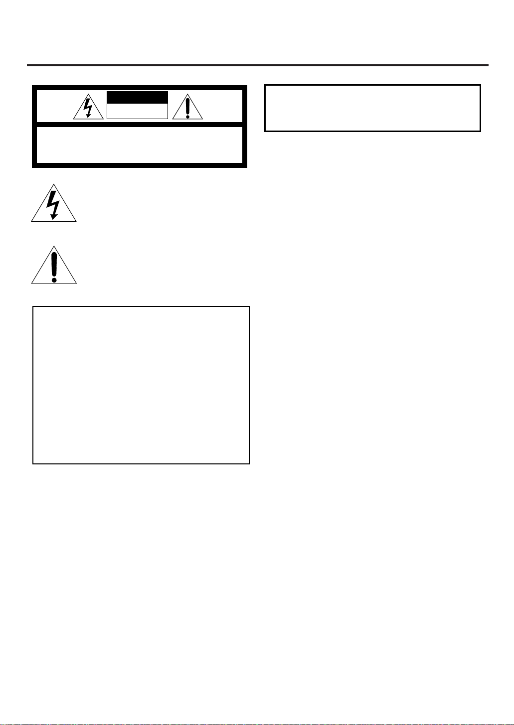
Front panel ————————————————————————————
s1a; oi uy trewq p9 8
243567
1 PHONES jack (9)
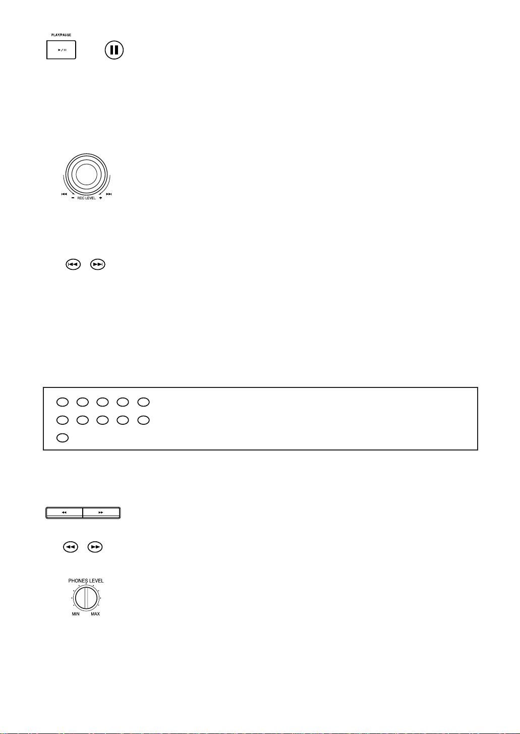
2 PHONES LEVEL control (9)
3 DISPLAY/CHARACTER button
(10, 26)
4 INPUT SELECTOR button (15)
5 Display
6 Jog dial (4, ¢/REC
LEVEL) (9, 16)
8 6 PLAY/PAUSE button (8, 9)
9 7 STOP/CANCEL button
(8, 11, 19, 27)
p ¶ REC PAUSE button (14)
q ENTER button (20, 27)
w SET button (11, 19, 26)
e EDIT button (19)
r TITLE button (26)
t 0 (Eject) button (8)
y MD insertion slot (8)
u Disc indicator (7, 14)
i REPEAT button (13)
o PLAY MODE button (10, 12)
; Remote sensor (5)
a POWER button (7)
s STANDBY indicator (7)
7 1, ¡ buttons (9)
Display ——————————————————————————————
wq p 9 8
DIGITAL 12
32kHz 44.1kHz 48kHz
L
40 30 20 15 10 6 3 0 dB
R
1
MD
TOC
OVER
RECREC
24356 7
1 Level indicators and OVER indicator (16)
2 TOC indicator (20)
3 REC indicator (14)
4 Play/Pause indicators (3 (Play), 8 (Pause)) (8, 9, 14)
5 MD editing mode indicators (19 – 25)
(DIVIDE, JOIN, MOVE, ERASE, ALL ERASE)
6 Repeat mode indicators (13)
(REPEAT ALL, REPEAT 1)
MD EDIT
DIVIDE
JOIN
MOVE
ALL ERASE
PROGRAM
RANDOM
REPEAT
ALL 1
7 Music calendar (19)
8 Play mode indicators (10, 12)
(PROGRAM, RANDOM)
9 Character display (11 digits) (26)
p MD indicator (7)
q Input mode indicators (15)
(DIGITAL 1, DIGITAL 2)
w Sampling frequency indicators (15)
(32 kHz, 44.1 kHz, 48 kHz)
11
16
1
2
3
4
5
6
7
8
9
10
12
13
14
15
17
18
19
20
3
Page 6
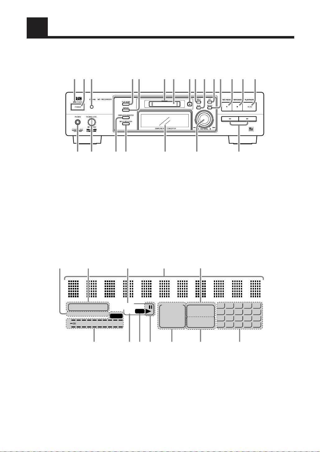
Remote control unit————————————————————————
Open the cover panel as shown below to access the
editing control button panel.
POWER
PROGRAMCANCEL RANDOM REPEAT
3
4
2
1
89
67
+10
ON/OFF
DIMMER MODE
TRACK MARKING
1¡ 4¢
¶37
RM-SXM448J REMOTE CONTROL
1
2
5
10
3
4
Inside panel
0
RM-SXM448J REMOTE CONTROL
5
8
378
SPACE
This button does
not function.
EDITTITLE
ENTERSET
CANCEL
SMALL
LETTER
76
POWER
1 POWER button
2 PLAY MODE buttons
CANCEL (11, 19, 28)
PROGRAM (11)
RANDOM (12)
REPEAT (13)
3 Numeric keys
4 DISPLAY buttons
ON/OFF (10)
DIMMER (10)
MODE (10)
5 MD control buttons
TRACK MARKING (16)
¶ (Recording Pause) (14)
8 (Pause) (9)
7 (Stop) (8)
3 (Play) (8)
4, ¢ (9)
1, ¡ (9)
0 (Eject) (8)
Buttons on the Inside Panel
6 Character input keyboard (28)
Numbers, Alphabets, and Symbols
7 MD editing buttons
TITLE (28)
EDIT (19)
SET (19, 28)
ENTER (20, 28)
3 (Play) (8)
CANCEL (19, 28)
< / 4, ¢ / > (20, 28)
SMALL LETTER (28)
4
Page 7
Setting up the System
Supplied accessories
Before setting up your system make sure you received all of the following supplied
accessories.
Remote control unit (1)
Batteries R03 (UM-4)/AAA (24F) (2)
Audio pin cord (2)
Optical digital cable (1)
Compu Link cable (1)
Text Compu Link cable (1)
AC power cord (1)
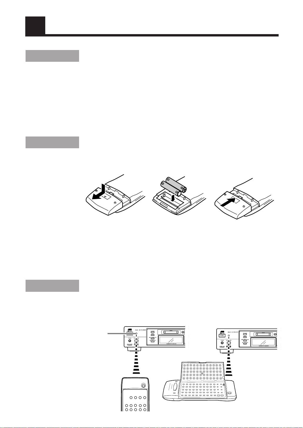
Remote control batteries
Match the polarity (+ and –) on the batteries with the + and – markings in the battery
compartment.
R03 (UM-4)/AAA (24F)
CAUTION: Handle batteries properly.
To avoid battery leakage or explosion:
• Remove batteries when the remote control unit will not be used for a long time.
• When you need to replace the batteries, replace both batteries at the same time with
new ones.
• Do not use an old battery with a new one.
• Do not use different types of batteries together.
Operating the remote control unit
The remote control unit makes it easy to use many of the functions of the system from a
distance of up to 7 m (23 feet) away.
You need to point the remote control unit at the remote sensor on the front panel.
Remote sensor
5
Page 8
Connection
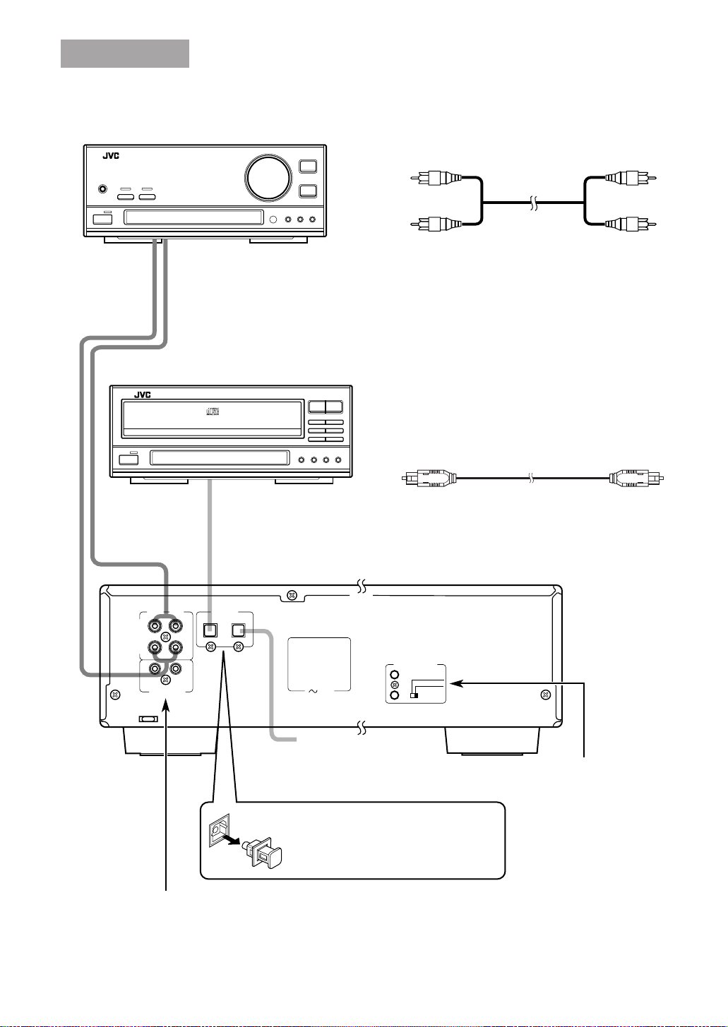
Signal cable connections ——————————————
Example: Amplifier/Tuner
Audio pin cords
Connect to the MD jacks, TAPE jacks, etc. of an external unit.
Always connect the jacks with the plugs of the same colors so as not to fail in the L
(Left) and R (Right) connections.
Connect the OUT (PLAY) jacks to the IN (PLAY) jacks of the external unit, and the IN
(REC) jacks to its OUT (REC) jacks.
Example: CD player
Audio pin cord (supplied)
Optical digital cable (supplied)
Optical digital cable
Connect to the DIGITAL OUT jack of the CD player, for
example.
DIGITAL IN
LEFTRIGHT
IN
(REC)
ANALOG
OUT
(PLAY)
COMPU LINK- 3
(SYNCHRO)
Connect to the COMPU LINK-3 (SYNCHRO) jack of another
JVC component equipped with the COMPU LINK remote control system.
See page 30.
1- OPTICAL- 2
TEXT COMPU LINK
1 (MASTER UNIT)
AC IN
2 (SLAVE UNIT)
Optical digital cable
Connect to the DIGITAL OUT
jack of your DBS tuner, etc.
Be sure to remove the protective cap
before using the DIGITAL IN terminals.
Keep the cap in a safe place so you can
replace it when not using the DIGITAL
IN terminals.
Connect to the TEXT
COMPU LINK jack of
another JVC component
equipped with the TEXT
COMPU LINK remote
control system.
See pages 31 and 32.
6
Page 9
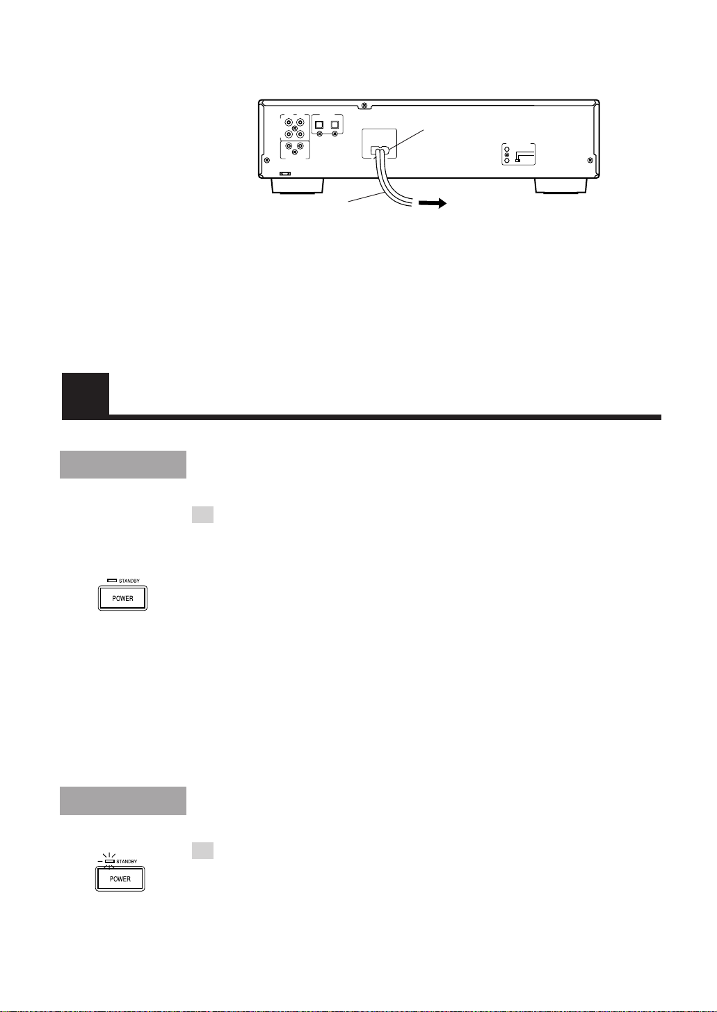
AC power cord connection —————————————
First, firmly insert the supplied AC power cord into the AC inlet on the back of the unit.
Next, plug the AC power cord plug into the wall outlet.
DIGITAL IN
LEFTRIGHT
1- OPTICAL- 2
IN
(REC)
ANALOG
(PLAY)
OUT
COMPU LINK- 3
(SYNCHRO)
AC IN
AC inlet
TEXT COMPU LINK
1 (MASTER UNIT)
2 (SLAVE UNIT)
AC power cord
To wall outlet
Cautions
• Use only the JVC AC power cord provided with this unit to
avoid malfunction or damage to the unit.
• Be sure to unplug the power cord from the outlet when
going out or when the unit is not in use for an extended
period of time.
Turning the Power On and Off
Power On
1 Press POWER on the main unit or on the remote control
unit.
The STANDBY indicator goes out, the disc indicator lights in green, and the display
comes on. The MD indicator lights up on the display.
When no MD is loaded:
“NO DISC” is shown on the display.
When an MD is already loaded:
The following messages are shown on the display in succession.
• “TOC Reading”
• The disc title, if the MD has.
• Number of tracks and the total playing time of the MD
You can play the MD by pressing 6 on the main unit or 3 on the remote control unit.
For detailed description, see “Playback” on the next page.
Power Off
1 Press POWER again.
The STANDBY indicator lights up, the disc indicator goes out, and the display blanks.
• Some power (7W) is always consumed even though power is turned off (called
Standby mode).
• To switch off the unit completely, unplug the AC power cord from the AC outlet.
7
Page 10
Playback
Continuous playback
The basic operation for playing an MD is described below. When no MD is loaded yet,
“NO DISC” is shown on the display.
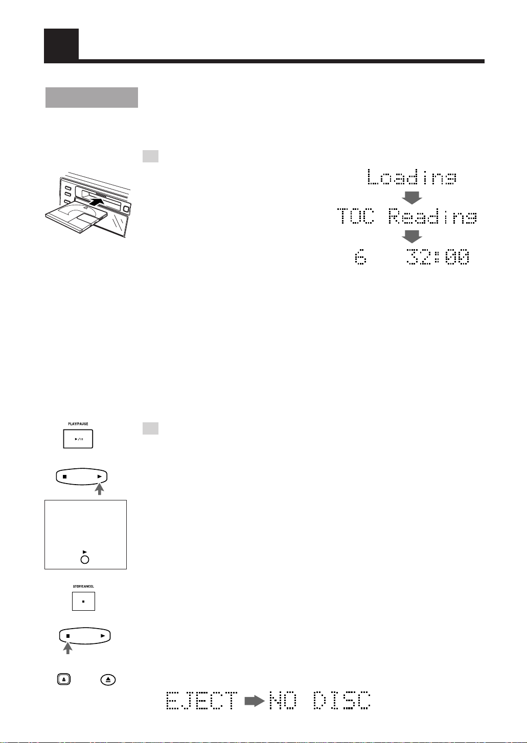
1 Load an MD.
Hold an MD with the side on which an
arrow is marked facing up, and insert it into
the slot in the direction of the arrow.
The MD will be pulled in automatically
from the middle.
• If the MD has a disc title, the display
shows the disc title then the number of
tracks and total playing time of the MD.
• The tracks in the MD appear on the
music calendar.
Note: To allow easy insertion, insert the MD along the upper part of the MD insertion
slot.
Caution
• Do not fail to observe the MD insertion direction, otherwise
a malfunction will result.
Number of tracks Total playing time
OR
You can also use
the button on the
inside panel of the
remote control.
OR
OR
Shortcut:
You can insert an MD in Standby mode. Then, the power is turned on and the MD is
pulled in automatically.
2 Press 6 on the main unit or 3 on the remote control unit.
Playback starts.
The 3 indicator blinks for a while and then stays lit.
The playback levels for the L and R channels are shown on the level indicators.
• If the track has a title, the track title will be displayed before playing the track.
• The track number that has been played disappears from the music calendar.
• The MD automatically stops when the last track of the MD has finished playing.
Shortcut:
When you press 6 on the main unit or 3 on the remote control unit in Standby mode,
the power is turned on and the MD is automatically played. However, if no MD is
loaded, “NO DISC” is shown on the display.
To stop the MD:
Press 7 on the main unit or on the remote control unit.
• If the MD has a disc title, the display shows the disc title then the number of tracks and
total playing time of the MD.
To eject the MD:
Press 0 on the main unit or on the remote control unit.
The MD is ejected and the display changes as follows:
8
Page 11
OR
To pause the MD:
Press 6 on the main unit or press 8 on the remote control unit.
The 8 indicator lights up.
To cancel pause, press 6 on the main unit or press 3 on the remote control unit. The MD
starts from the position where it has paused.
To select a track ——————————————————
You can select a desired track during playback or in Stop mode.
Main unit:
During playback, turn the jog dial to the right or left to select the track you want. Then, the
selected track starts playing.
• Turn the jog dial to the right to skip to the beginning of the next tracks.
• Turn the jog dial to the left to return to the beginning of the current track (or the
previous tracks).
In Stop mode, you can select a track in the same way. To start playback, press 6.
Remote control unit:
Using 4 or ¢ :
During playback, press 4 or ¢ to select the track you want. Then, the selected
track starts playing.
• Press ¢ to skip to the beginning of the next tracks.
• Press 4 once to return to the beginning of the current track (or the previous
tracks).
2
1
67
+
10
OR
In Stop mode, you can select a track in the same way. To start playback, press 3.
Using the numeric keys:
During playback or in Stop mode, select a track with the numeric keys. Then, the
selected track starts playing.
3
4
89
5
10
Selecting a track with the numeric keys:
To select track No. 5 : Press 5.
To select track No. 15: Press +10 then 5.
To select track No. 20: Press +10 then 10.
To select track No. 52: Press +10 five times then press 2.
• When you try to select a track number greater than the recorded tracks in the MD,
the last track is automatically selected.
Search play —————————————————————
During playback, you can fast forward/backwards the MD to quickly find a particular
passage in the track.
To perform this, press and hold 1 or ¡ on the main unit or on the remote control unit.
Using headphones —————————————————
Connect a pair of headphones (not supplied) to the PHONES jack to listen to the playback
sound of the MD or rec-monitor sound.
You can adjust the headphones output level by turning the PHONES LEVEL control.
• The output from the unit is not cut off even if the headphones are used.
Caution
• Be sure to turn down the PHONES LEVEL control before
connecting or putting on headphones.
9
Page 12
Using the display mode
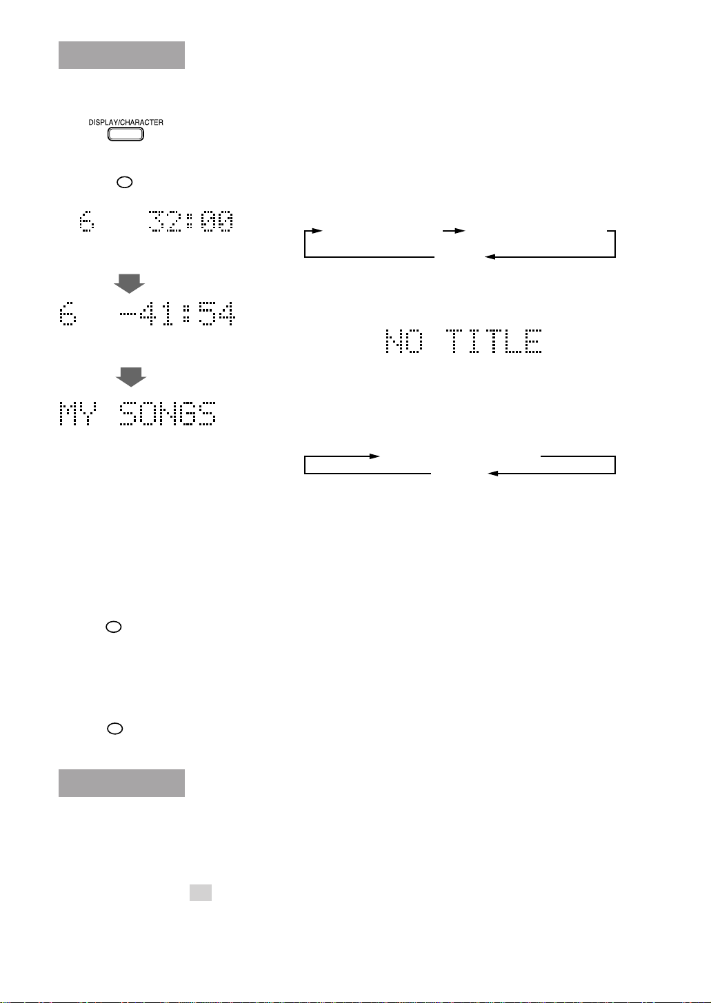
To switch the display information —————————
The display can show the disc title, track title and remaining time (recording time available
when a recordable MD is loaded) information.
OR
MODE
Number of tracks and total
playing time
Number of tracks and remaining
recording time
Disc title
When no track is selected (In Stop mode):
Press DISPLAY/CHARACTER on the main unit or MODE on the remote
control unit.
Each press of the button switches the displayed information as follows.
Number of tracks and
total playing time
Disc title
• A disc title composed of more than 11 characters is scrolled, and the
first 11 characters are displayed after scrolling.
• The display shows “NO TITLE” if the disc has no title.
Number of tracks and
remaining recording time
When a track has already been selected (During
playback or in Stop mode):
Press DISPLAY/CHARACTER on the main unit or MODE on the remote
control unit.
Each press of the button switches the displayed information as follows.
Track No. and its playing time
Track title
• A track title composed of more than 11 characters is scrolled, and the
first 11 characters are displayed after scrolling.
Note: When using the TEXT COMPU LINK remote control system
(see page 31), titles will not be scrolled.
• The display shows “NO TITLE” if the track has no title.
10
ON/OFF
DIMMER
To change the brightness of the display ——————
• You can turn on or off the display by pressing ON/OFF on the remote control unit. Each
press of the button turns on or off the display alternately.
When you turn off the unit, the display-off mode is canceled.
Notes: • When editing MDs or assigning titles (see pages 17 to 29), you cannot turn on
or off the display.
• Even though the display is turned off, it turns on temporarily while you
operate the unit (for example, pause or stop) during play or recording.
• You can dim the display by pressing DIMMER on the remote control unit. Each press
of the button turns the display dim or bright alternately.
Program playback
You can program up to 32 tracks in any desired order including the same tracks.
• You can only make a program in Stop mode.
1 Load an MD.
See “Continuous playback ” on page 8.
Page 13
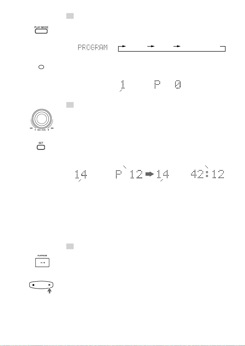
2 Select Program Play mode.
Main unit:
Press PLAY MODE until “PROGRAM” is shown. Then, the PROGRAM indicator
lights up.
Each time PLAY MODE is pressed, the play mode indicators switch as follows:
PROGRAM RANDOM Off (Continuous play)
PROGRAM
Remote control unit:
Press PROGRAM. “PROGRAM” is shown and the PROGRAM indicator lights up.
The display shows the following for programming.
The first track
3 Select desired track numbers to be programmed.
Main unit:
1 Turn the jog dial to the right or left to select the desired track number to be
programmed. (Turning it to the right increases the track number and vice versa.)
The selected track number will blink.
2 Press SET.
The track number stays lit and the program number increases by 1. Also, the
programmed track is indicated on the music calendar.
Then, the total playing time is displayed instead of the program number.
Example)
The last programmed track
3 Repeat steps 1 and 2 to select the other tracks for the program.
Program number
Total playing time
The last programmed track
OR
Remote control unit:
1 Select the desired track number with the numeric keys.
The selected track number is programmed and the program number is displayed.
Then, the total playing time is displayed instead of the program number.
To select a track, see “Selecting a track with the numeric keys” on page 9.
2 Repeat step 1 to select the other tracks for the program.
4 Press 6 on the main unit or 3 on the remote control
unit.
Program playback starts in the programmed order.
• Program playback stops after having played all programmed tracks.
• To stop playing, press 7 on the main unit or on the remote control unit.
• To skip programmed tracks, turn the jog dial on the main unit to the right or press
¢ on the remote control unit.
To return to the beginning of the current track or previous tracks, turn the jog dial
on the main unit to the left or press 4 on the remote control unit.
11
Page 14
OR
CANCEL
PROGRAM
To check the programmed tracks and their order (In Stop
mode):
Press 4 or ¢ on the remote control unit in Stop mode. The programmed tracks will be
successively displayed in the programmed order. (The track title will be displayed before
the track number, if it is written.)
If you make a mistake in programming (In Stop mode):
Press 7 STOP/CANCEL on the main unit or CANCEL on the cover panel of the remote
control unit in Stop mode to clear the last track. Each press of the button clears the last
track in the program.
Press the button repeatedly until the track you do not want is cleared and then re-program
tracks from that point.
To cancel Program Play mode (In Stop mode):
Main unit:
Press PLAY MODE in Stop mode to select any mode other than Program Play mode.
Remote control unit:
Press PROGRAM in Stop mode to turn off the PROGRAM indicator.
The program contents remain in memory even after the unit has exited from Program Play
mode.
OR
To clear the program:
Press 0 on the main unit or on the remote control unit.
The programmed tracks are cleared then the MD is ejected.
Note: The program contents are cleared from memory when the power cord is unplugged
or in case of power failure.
To play programmed tracks repeatedly:
Combine the program playback and repeat playback to play the programmed tracks
repeatedly.
For the repeat playback, see page 13.
Random playback
Tracks in the MD can be played at random. Random Play may bring you a surprising effect
by playing tracks in a different order every time.
• You can only select Random Play in Stop mode.
1 Load an MD.
See “Continuous playback” on page 8.
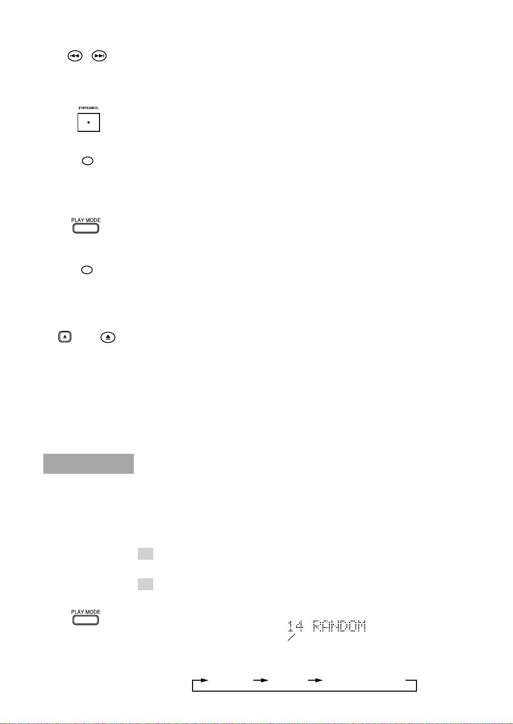
2 Select Random Play mode.
Main unit:
Press PLAY MODE until “RANDOM” is shown. Then, the RANDOM indicator lights
up.
12
Number of tracks
Each time PLAY MODE is pressed, the play mode indicators switch as follows:
PROGRAM RANDOM Off (Continuous play)
Page 15

Remote control unit:
RANDOM
OR
RANDOM
Press RANDOM. “RANDOM” is shown and the RANDOM indicator lights up.
3 Press 6 on the main unit or 3 on the remote control unit.
Random playback starts.
• Random playback stops after having played every track once.
• To stop playing, press 7 on the main unit or on the remote control unit.
To cancel Random Play mode (In Stop mode):
Main unit:
Press PLAY MODE in Stop mode to select any mode other than Random Play mode.
Remote control unit:
Press RANDOM in Stop mode to turn off the RANDOM indicator.
To repeat random playback:
Combine the random playback and repeat playback to play tracks repeatedly in random
orders. The order tracks are played differs every time random playback is repeated.
For the repeat playback, see below.
Repeat playback
OR
OR
OR
REPEAT
REPEAT
You can repeat all the tracks or a single track in each playback mode.
1 Press REPEAT on the main unit or on the remote control
unit to select Repeat Play mode.
Each time REPEAT is pressed, the repeat mode indicators switch as follows:
REPEAT ALL REPEAT 1
Off (Repeat playback canceled)
REPEAT ALL: In Continuous Play mode, repeats all the tracks.
In Program Play mode, repeats all the tracks in the program.
In Random Play mode, repeats all the tracks at random.
REPEAT 1: Repeats one track.
2 Press 6 on the main unit or 3 on the remote control
unit.
Repeat playback starts.
• To stop playing, press 7 on the main unit or on the remote control unit.
To cancel repeat playback:
Press REPEAT on the main unit or on the remote control unit until the repeat mode
indicator goes out.
13
Page 16

Recording
An audio signal from a variety of sources can be recorded by using either digital or analog
input as required.
Things to know before recording ——————————
• It should be noted that it may be unlawful to re-record pre-recorded tapes,
records, or discs without the consent of the owner of copyright in the
sound or video recording, broadcast or cable programme and in any
literary, dramatic, musical, or artistic embodied therein.
• Carefully read the “Rule on Digital Copying” on page 33.
• The MD recorder supports the following sampling frequencies for digital sources and
lights the sampling frequency being received on the display.
32 kHz, 44.1 kHz and 48 kHz
• Recording level adjustment:
When recording through a digital input terminal, the recording level is automatically set
correctly.
When recording through an analog input terminal, it is necessary to adjust the recording
level properly.
• The accidental erasure protect tab is provided on the back of an MD cartridge to prevent
accidental erasure or recording. It must be set to the close position before recording.
Otherwise, “DISC PROTECTED” will appear when you try to record a signal to the
MD.
Accidental erasure protect tab
OR
Close Open
For recording
or editing
• When you stick an adhesive label onto the MD cartridge, adhere it securely. If it peels
off, ejection trouble, etc. will occur.
• Be sure that the MD is not of Playback-only type. (See “Two disc types” on page 34.)
• Be sure that the MD has enough space for recording. If not, carry out ALL ERASE or
ERASE function to erase all the tracks or unwanted tracks in the MD. You can check
the recordable remaining time of the MD. (See “To display the remaining recording
time” on page 16.)
For protecting
erasure
Recording operation
1 Load a recordable MD.
2 Press ¶ REC PAUSE on the main unit or ¶ on the remote
control unit.
The MD recorder enters Rec/Pause mode. The REC and 8 (Pause) indicators light up
and the first track to be recorded is displayed. Also, the disc indicator lights in red.
Example) When 14 tracks are already recorded
14
The first track to
be recorded
REC
Page 17

3 Select the input by pressing INPUT SELECTOR on the
main unit.
Each press of INPUT SELECTOR switches the inputs as follows.
DIGITAL1 IN DIGITAL2 IN ANALOG IN
DIGITAL1 IN : Select this to record the digital input from the digital source
component connected to the DIGITAL IN 1 OPTICAL terminal.
The DIGITAL 1 indicator lights up.
DIGITAL2 IN : Select this to record the digital input from the digital source
component connected to the DIGITAL IN 2 OPTICAL terminal.
The DIGITAL 2 indicator lights up.
ANALOG IN : Select this to record the analog input from the analog source
component (cassette deck, tuner, etc.) connected to the ANALOG IN
(REC) jacks.
4 Play the source to be recorded.
The level indicators show the input levels.
• The input level should be adjusted when the analog input is recorded (see “To adjust
the analog input level” on page 16).
• The input level for the digital inputs does not need adjustment.
• When DIGITAL 1 or DIGITAL 2 is selected, one of the sampling frequency
indicators lights up. For example, 44.1 kHz indicator is displayed for a CD player
input.
However, if no source component is connected to
the digital input or the sampling frequency input is
other than 32 kHz, 44.1 kHz, or 48 kHz,
“DIGITAL IN UNLOCK” scrolls on the display
showing that the recording is impossible.
DIGITAL 1
44.1kHz
OR
OR
OR
5 Press 6 on the main unit or 3 on the remote control unit.
Recording starts.
The 3 indicator lights up.
• When the MD becomes full, “UTOCwriting” is displayed indicating that the
recording is successfully completed. Then, the MD stops. The disc indicator lights
in green.
To stop recording:
Press 7 on the main unit or on the remote control unit.
“UTOCwriting” is displayed and the MD stops. The disc indicator lights in green.
To pause the MD:
Press ¶ REC PAUSE on the main unit or ¶ on the remote control unit.
To resume recording, press 6 on the main unit or 3 on the remote control unit.
15
Page 18

OR
TRACK MARKING
OR
MODE
To adjust the analog input level ——————————
The input level should be adjusted before recording the analog input.
1 In Rec/Pause mode, start playing the source for level adjustment.
The level indicators show the input levels.
2 Turn the jog dial on the main unit to the right or left or press ¢ or 4 on the remote
control unit to increase or decrease the recording level.
As you adjust the recording level, “VOL. –10” will appear, for example. You can adjust
the recording level between VOL.–50 and VOL.0 (–50 dB and 0 dB), or to VOL. – – –
(below –50 dB).
L
40 30 20 15 10 6 3 0 dB
R
• Normally the input level should be adjusted so that the segments for 0 dB blink at the
peak level.
• When the input level is too high, the OVER indicator will light up, resulting in distorted
recording.
To display the remaining recording time ——————
In Rec/Pause or during recording, press DISPLAY/CHARACTER on the main unit or
MODE on the remote control unit.
Each press of the button switches the elapsed recording time display and remaining
recording time display alternately.
OR
SET
remaining recording time
Track marking ———————————————————
The track numbers on the MD are marked at the beginning of each track. The track numbers
are identified by these “track markings” and each section between two track markings is
considered as a track.
For analog input:
When the point you want to record a track marking comes during recording, press SET on
the main unit or on the inside panel of the remote control unit. This operation records a
track marking at the point where the button is pressed.
To use automatic track marking:
Press TRACK MARKING on the remote control unit to select “AUTO”.
• A track marking is automatically recorded every time a blank of more than 3
seconds is detected.
To cancel automatic track marking, press TRACK MARKING on the remote control
unit again to select “MANUAL”.
For digital input:
When tracks are recorded from a CD player by digital input, track markings are recorded
automatically at the points where the CD tracks change.
16
Page 19

Editing Functions
MD editing functions
A recorded MD can be edited in many ways. The editing functions include the dividing,
joining, moving, erasing a single track, erasing the entire disc and assigning titles to the
disc and tracks, and more than one of them can be combined as required.
• Editing operations are possible both while the MD recorder is playing and while it is in
Stop mode.
After track B
division
After track B
joining
After track B
movement
After track B
erasure
1st
B C DA E
2nd
1st
B
A
2nd
1st
B
A
1st
BA
2nd
1st
B
A
2nd
1st
C D E
A
2nd
1st
B
A
2nd
1st
C D E
A
2nd
3rd 4th
3rd 4th
C D
3rd 4th 5th
C D E
2nd
3rd 4th
C D E
3rd 4th 5th
C D E
3rd 4th 5th
3rd 4th 5th
C D E
3rd 4th
Dividing a track (DIVIDE) Page 19
Track No.
5th
E
This function divides a track by adding a track marking(s) in
desired point(s) in the middle or where you want to search later.
Joining tracks (JOIN) Page 20
Track No.
This function joins two adjacent tracks into a single track by
deleting a track marking in between.
Moving a track (MOVE) Page 22
Track No.
B
This function moves a track by reordering the track numbers.
Erasing a track (ERASE) Page 23
Track No.
This function erases a specified track. After the erasure, the
subsequent tracks are renumbered automatically.
After
All Erase
2nd
1st
A
B
3rd 4th 5th
C D E
Track No.
Erasing all tracks (ALL ERASE) Page 25
This function erases data in a disc entirely.
17
Page 20

Dividing track A
into 3 tracks
Erasing track
Joining
tracks and
a c
A
A
a
b
A
a c
A
a c
Part to be erased
1st
2nd
1st
A
A
b
1st
2nd
A
B
1st
A
B
2nd
3rd
B C
3rd
4th
5th
C
B
c
4th
3rd
C
2nd
3rd
C
Combining editing functions
By combining “DIVIDE”, “ERASE” and “JOIN”, for
example, it is possible to erase only a part of existing track.
Track No.
Track No.
Track No.
Assigning titles
A title can be assigned to a track or disc. Once a title is
assigned, it is displayed in later playback for confirmation.
Each title can be composed of up to 64 characters, and can
be input using any of character types, alphabets (uppercase
and lowercase), symbols and numerals.
When using the remote control unit:
For editing and title assignment operations, use the buttons on the inside panel of the
remote control unit.
RM-SXM448J REMOTE CONTROL
378
SPACE
EDITTITLE
ENTERSET
CANCEL
SMALL
LETTER
POWER
18
Page 21

OR
EDIT
Dividing a track (DIVIDE)
A track can be divided into desired number of tracks by adding track markings in the
middle, in the desired points or where you want to search later.
This makes it possible to assign track numbers after recording medley music or FM
broadcast. The track numbers after the divided track are renumbered automatically.
1 Press EDIT on the main unit or on the remote control unit
to select “DIVIDE”.
The DIVIDE indicator lights up.
Each press of the button switches the editing functions as follows.
DIVIDE JOIN MOVE
ERASE
ALL ERASE
OR
OR
OR
OR
SET
SET
(MD total playing time display or Disc title)
Canceled
Blinks
345
2
1
6
2 Press SET on the main unit or on the remote control unit.
Blinks
Blinks
2
1
6
345
3 Play a track to be divided.
Select a track number by turning the jog dial on the main unit or by pressing < / 4 or
¢ / > on the remote control unit.
Then, press 6 on the main unit or 3 on the remote control unit.
Blinks
Blinks
345
2
1
6
Example)
When track No. 3 is selected
• You can also use the numeric keys on the cover panel of the remote control unit to
select the track number. To select a track, see “Selecting a track with the numeric
keys” on page 9.
• You can use ¡ (or 1) to fast forward (or reverse) the track.
4 Press SET when a point where you want to divide the
track comes.
“POSITION” is displayed and the track marking fine-adjustment display appears.
Blinks
Blinks
345
2
1
6
7
Increments by 1
Example) Track No. 3 and 4 blink in the music
calendar and the 4-second section from the
divided point will be played repeatedly.
• When the track has been divided as desired, go to step 6.
• If the track has not been divided as desired, fine-adjust the track marking position.
Go to step 5.
• If you notice that the selected track number is wrong, press 7STOP/CANCEL on
the main unit or CANCEL on the remote control unit and repeat from step 3.
• If the display shows “TRACK PROTECTED”, the selected track has been protected
against accidental erasure by another component. You cannot edit such a protected
track. To cancel the editing, press EDIT on the main unit or on the remote control
unit.
19
Page 22

OR
5 Fine-adjust the track marking position.
Turn the jog dial on the main unit or press < / 4 or ¢ / > on the remote control
unit.
The track marking position can be fine-adjusted in the range of ±128 positions (approx.
±8 sec.).
As you adjust, the track marking is displaced slightly and the 4-second section from the
newly divided point will be played repeatedly.
• After completing the fine-adjustment, go to step 6.
• To cancel the current track marking position, press 7STOP/CANCEL on the main
unit or CANCEL on the remote control unit and repeat from step 3.
OR
OR
ENTER
6 Press ENTER on the main unit or on the remote control
unit.
The change made above is entered
temporarily in memory. The display shows
“EDITING” and the TOC indicator lights
up.
345
2
1
6
7
TOC indicator:
The TOC indicator shows that the MD has new data that should be memorized.
The data writing operation is done by ejecting the MD or by turning the power off.
Before the MD is ejected or the power is turned off, “UTOCwriting” is displayed until
the data is completely written.
7 Press 0 on the main unit or on the cover panel of the
remote control unit to eject the MD.
The data in memory is written in the MD before it is ejected.
The display shows “UTOCwriting” during MD writing operation.
• Be careful not to apply impact to the MD recorder during writing temporarily stored
data into the MD. Otherwise the recording may not be able to play later.
• The data in memory is written in the MD also when the power is turned off while
“EDITING” is being displayed.
To cancel editing:
Press EDIT repeatedly on the main unit or on the remote control unit before pressing
ENTER in step 6.
To restore the original track from the divided tracks:
Use the JOIN editing function mentioned below.
20
OR
EDIT
Joining tracks (JOIN)
Two adjacent tracks can be joined into a single track by deleting an unnecessary track
marking. This also makes it possible to join more than two tracks into a single track or a
piece of music divided into multiple tracks into a single piece. The track numbers after the
joined tracks are renumbered automatically.
1 Press EDIT on the main unit or on the remote control unit
to select “JOIN”.
The JOIN indicator lights up.
Each press of the button switches the editing functions as follows.
DIVIDE JOIN MOVE
Canceled
(MD total playing time display or Disc title)
ERASE
ALL ERASE
Blinks
345
2
1
6
Page 23

OR
OR
OR
SET
SET
2 Press SET on the main unit or on the remote control unit.
Blinks
Blinks
345
2
1
6
3 Select a track to be joined with the previous track.
Select a track number by turning the jog dial on the main unit or by pressing < / 4 or
¢ / > on the remote control unit.
Blinks
Blinks
345
2
1
6
Example)
When track No. 1 and 2 are selected
• You can also use the numeric keys on the cover panel of the remote control to select
a track number. To select a track, see “Selecting a track with the numeric keys” on
page 9.
Example) To join track numbers 1 and 2, select track number 2.
4 Press SET on the main unit or on the remote control unit.
The selected track numbers blink in the music calendar, indicating that these tracks will
be joined into one.
Blinks
• If you selected wrong track numbers, press 7STOP/CANCEL on the main unit or
CANCEL on the remote control unit and repeat from step 3.
• If the display shows “TRACK PROTECTED”, one of the selected tracks has been
protected against accidental erasure by another component. You cannot edit such a
protected track. To cancel the editing, press EDIT on the main unit or on the remote
control unit.
Blinks
2
1
6
345
OR
OR
ENTER
5 Press ENTER on the main unit or on the remote control
unit.
The change made above is entered temporarily in memory. The display shows
“EDITING” and the TOC indicator lights up.
345
2
1
Decrements by 1
6 Press 0 on the main unit or on the cover panel of the
remote control unit to eject the MD.
The data in memory is written in the MD before it is ejected.
The display shows “UTOCwriting” during MD writing operation.
• Be careful not to apply impact to the MD recorder during writing temporarily stored
data into the MD. Otherwise the recording may not be able to play later.
• The data in memory is written in the MD also when the power is turned off while
“EDITING” is being displayed.
To cancel editing:
Press EDIT repeatedly on the main unit or on the remote control unit before pressing
ENTER in step 5.
To restore the original tracks from the track obtained by
joining:
Use the DIVIDE editing function.
See “Dividing a track (DIVIDE)” on page 19.
21
Page 24

OR
EDIT
Moving a track (MOVE)
A track can be moved to the desired position by selecting its track number and the
destination track number.
1 Press EDIT on the main unit or on the remote control unit
to select “MOVE”.
The MOVE indicator lights up.
Each press of the button switches the editing functions as follows.
DIVIDE JOIN MOVE
ERASE
ALL ERASE
OR
OR
OR
SET
(MD total playing time display or Disc title)
Canceled
Blinks
2 Press SET on the main unit or on the remote control unit.
The current track number will blink on the display.
Blinks
Blinks
3 Select a track number to be moved, then press SET.
Select a track number by turning the jog dial on the main unit or by pressing < / 4 or
¢ / > on the remote control unit.
Then press SET on the main unit or on the remote control unit.
Blinks
345
2
1
6
SET
Blinks
SET
Blinks
Example) When track No. 2 is to be moved
• You can also use the numeric keys on the cover panel of the remote control unit to
select a track number, then press SET. To select a track, see “Selecting a track with
the numeric keys” on page 9.
• If you selected a wrong track number, press 7STOP/CANCEL on the main unit or
CANCEL on the remote control unit and select the correct track number.
4 Select the movement destination track number, then
press SET.
Select another track number to be given to the selected track by turning the jog dial on
the main unit or by pressing < / 4 or ¢ / > on the remote control unit.
Then press SET on the main unit or on the remote control unit.
Blinks Blinks
SET
Example) When track No. 5 is selected
• You can also use the numeric keys on the cover panel of the remote control unit to
select the track number, then press SET. To select a track, see “Selecting a track
with the numeric keys” on page 9.
• If you selected a wrong track number, press 7STOP/CANCEL on the main unit or
CANCEL on the remote control unit and repeat from step 3.
Blinks
345
2
1
6
SET
345
2
1
6
345
2
1
6
Blinks
Blinks
22
Page 25

OR
OR
ENTER
5 Press ENTER on the main unit or on the remote control
unit.
The change made above is entered temporarily in memory. The display shows
“EDITING” and the TOC indicator lights up.
345
2
1
6
6 Press 0 on the main unit or on the cover panel of the
remote control unit to eject the MD.
The data in memory is written in the MD before it is ejected.
The display shows “UTOCwriting” during MD writing operation.
• Be careful not to apply impact to the MD recorder during writing temporarily stored
data into the MD. Otherwise the recording may not be able to play later.
• The data in memory is written in the MD also when the power is turned off while
“EDITING” is being displayed.
To cancel editing:
Press EDIT repeatedly on the main unit or on the remote control unit before pressing
ENTER in step 5.
Erasing a track (ERASE)
A track can be erased from the MD. The track numbers after the erased track are
renumbered automatically.
OR
OR
EDIT
SET
1 Press EDIT on the main unit or on the remote control unit
to select “ERASE”.
The ERASE indicator lights up.
Each press of the button switches the editing functions as follows.
DIVIDE JOIN MOVE
Canceled
(MD total playing time display or Disc title)
ERASE
ALL ERASE
Blinks
345
2
1
6
2 Press SET on the main unit or on the remote control unit.
The current track number will blink on the display.
Blinks
Blinks
Blinks
2
1
6
345
23
Page 26

OR
3 Select a track number to be erased, then press SET.
Select a track number by turning the jog dial on the main unit or by pressing < / 4 or
¢ / > on the remote control unit.
Then press SET on the main unit or on the remote control unit.
Blinks
Blinks
Blinks
345
2
1
6
OR
OR
ENTER
SET
Example) When track No. 2 is to be erased
Blinks
Blinks
2
1
6
Example) When SET is pressed
• You can also use the numeric keys on the cover panel of the remote control unit to
select a track number, then press SET. To select a track, see “Selecting a track with
the numeric keys” on page 9.
• If you selected a wrong track number, press 7STOP/CANCEL on the main unit or
CANCEL on the remote control unit and select the correct track number.
• If the display shows “TRACK PROTECTED”, the selected track has been protected
against accidental erasure by another component. You cannot edit such a protected
track. To cancel the editing, press EDIT on the main unit or on the remote control
unit.
4 Press ENTER on the main unit or on the remote control
unit.
The change made above is entered temporarily in memory. The display shows
“EDITING” and the TOC indicator lights up.
2
1
Decrements by 1
5 Press 0 on the main unit or on the cover panel the remote
control unit to eject the MD.
The data in memory is written in the MD before it is ejected.
The display shows “UTOCwriting” during MD writing operation.
345
345
24
• Be careful not to apply impact to the MD recorder during writing temporarily stored
data into the MD. Otherwise the recording may not be able to play later.
• The data in memory is written in the MD also when the power is turned off while
“EDITING” is being displayed.
To cancel editing:
Press EDIT repeatedly on the main unit or the remote control unit before pressing ENTER
in step 4.
Caution
• Once erased, the track can never be restored. An MD
containing recording that you do not want to erase should
be protected by sliding the protect tab (see page 14).
Page 27

Erasing all tracks in an MD
(ALL ERASE)
The data recorded in an MD can be erased entirely.
OR
OR
OR
EDIT
SET
ENTER
1 Press EDIT on the main unit or on the remote control unit
to select “ALL ERASE”.
The ALL ERASE indicator lights up.
Each press of the button switches the editing functions as follows.
DIVIDE JOIN MOVE
Canceled
(MD total playing time display or Disc title)
ERASE
ALL ERASE
Blinks
345
2
1
6
2 Press SET on the main unit or on the remote control unit.
Blinks
345
2
1
6
• If the display shows “TRACK PROTECTED”, one or more of the tracks in the MD
has been protected against accidental erasure by another component. You cannot
edit such a protected track. To cancel the editing, press EDIT on the main unit or on
the remote control unit.
3 Press ENTER on the main unit or on the remote control
unit.
The change made above is entered temporarily in memory. The display shows
“EDITING” and the TOC indicator lights up.
OR
4 Press 0 on the main unit or on the cover panel of the
remote control unit to eject the MD.
The data in memory is written in the MD before it is ejected.
The display shows “UTOCwriting” during MD writing operation.
• Be careful not to apply impact to the MD recorder during writing temporarily stored
data into the MD. Otherwise the recording may not be able to play later.
• The data in memory is written in the MD also when the power is turned off while
“EDITING” is being displayed.
To cancel editing:
Press EDIT repeatedly on the main unit or on the remote control unit before pressing
ENTER in step 3.
Caution
• Once erased, the tracks can never be restored. An MD
containing recording that you do not want to erase should
be protected by sliding the protect tab (see page 14).
25
Page 28

Assigning the disc title and track
titles
You can assign a title to each MD and to each track. Once a title is assigned, it is displayed
for later playback for confirmation.
Each title can be composed of up to 64 characters, and can be input using alphabetic
characters — uppercase (A to Z) and lowercase (a to z), symbols (see “Available symbols”
on the next page), and numerals (0 to 9).
To assign a title using the buttons on the main unit
In the following example, the process is explained from the very first — that is, inserting an
MD. If you already start recording or playing, see “To assign a track title during playback
or recording” on page 29.
1 Load a recorded MD.
2 Press TITLE.
The display will show “DISC/NO TITLE”.
Each press of the button switches the title assignment function on and off.
Blinks
• If a disc title has already been assigned, the title is displayed.
When you assign the disc title: Go to step 3.
When you assign the track titles:
First select the track to be titled by turning the jog
dial to the right or left. Then, go to step 3.
Blinks
3 Press SET.
The title assignment display appears.
The display is divided into the title name area and the character set area.
Cursor
(blinks)
4 Enter a character
Example: When entering character “n”.
1 Press DISPLAY/CHARACTER repeatedly.
Each press of the button changes the character sets as follows:
Capital letters
& Symbols
Numerals
2 Turn the jog dial until “n” blinks on the character set area.
• Turning the jog dial continuously can also change the character sets.
3 Press SET.
The selected character is entered, and the cursor moves to the next character entry
position.
Title name area
Small letters
& Symbols
Alternately blinks
Scrolls
Scrolls
Character set
area
26
Page 29

• To enter a space, press ¡ to move the cursor to the right (or turn the jog dial to
select a space, then press SET).
• To move the cursor while entering a title, press 1 or ¡.
• If you have entered an incorrect character, press 7STOP/CANCEL to cancel the
last entry.
To make a correction or change the title:
1 Press 1 or ¡ to move the cursor on an incorrect character, and press
7STOP/CANCEL.
2 Turn the jog dial to select the correct character, then press SET.
To erase all the input characters:
Press 7STOP/CANCEL repeatedly until all the input characters are erased.
5 Press ENTER.
The display shows “EDITING” and the TOC indicator lights up.
Next, the display shows the disc title name and then shows the track number and the
total playing time.
(Disc Title)
• If the disc title is longer than 11 characters, it scrolls on the display.
Note: When using the TEXT COMPU LINK remote control system (see page 31),
titles will not be scrolled.
• After editing the track title, the name of the track is not displayed.
6 Press 0 to eject the MD.
The data in memory is written in the MD before it is ejected.
The display shows “UTOCwriting” during MD writing operation.
• Be careful not to apply impact to the MD recorder during writing temporarily stored
data into the MD. Otherwise the title may not be able to appear during a later
playback.
• The data in memory is written in the MD also when the power is turned off while
“EDITING” is being displayed.
To cancel editing:
Press TITLE before pressing ENTER in step 5.
Available symbols
(Space)
27
Page 30

To assign a title using the buttons on the remote
control unit
In the following example, the process is explained from the very first — that is, inserting an
MD. If you already start recording or playing, see “To assign a track title during playback
or recording” on page 29.
1 Load a recorded MD.
SPACE
TITLE
SET
SMALL
LETTER
2 Press TITLE.
The display shows “DISC/NO TITLE”.
Blinks
Scrolls
• If a disc title has already been assigned, the title is displayed.
If you want to assign the disc title, go to step 3.
If you want to assign the track titles, press < / 4 or ¢ / > to select the track to
be titled then go to step 3.
3 Press SET.
The cursor starts blinking on the first character entry position.
4 Input the disc or track title.
1 Select the character case.
Each press of SMALL LETTER switches the character case.
Lowercase letters can be input when the button is lit in green, and uppercase letters
can be input when the button is not lit.
2 Input characters by using the character input keyboard.
The selected character is entered, and the cursor moves to the next character entr y
position.
• To move the cursor while entering a title, press < / 4 or ¢ / >.
• If you have entered an incorrect character, press CANCEL to cancel the last
entry.
28
ENTER
To make a correction or change the title:
1 Press < / 4 or ¢ / > to move the cursor on an incorrect character, and press
CANCEL.
2 Input the correct character by using the character input keyboard.
To erase all the input characters:
Press CANCEL repeatedly until all the input characters are erased.
5 Press ENTER.
The display shows “EDITING” and the TOC indicator lights up.
Next, the display shows the disc title name and then shows the track number and the
total playing time.
(Disc Title)
Page 31

OR
6 Press 0 to eject the MD.
The data in memory is written in the MD before it is ejected.
The display shows “UTOC writing” during MD writing operation.
• Be careful not to apply impact to the MD recorder during writing temporarily stored
data into the MD. Otherwise the title may not be able to appear during a later
playback.
• The data in memory is written in the MD also when the power is turned off while
“EDITING” is being displayed.
To cancel editing:
Press TITLE before pressing ENTER in step 5.
To assign a track title during playback or recording
You cannot assign a disc title during playback or recording. To assign a disc title, follow the
procedure explained on pages 26 to 28.
1 Press TITLE on the main unit or on the remote control
TITLE
during playback or recording.
Each press of the button switches the title assignment function on and off.
• You can assign a title to the currently playing or recording track.
2 Input the track title name.
OR
OR
ENTER
• For detailed description, refer to pages 26 to 28.
However, note that the function of 7STOP/CANCEL on the main unit differs. If
you press the button, MD recorder stops playing or recording and finishes the title
assignment procedure at this point (“EDITING” appears).
3 Press ENTER on the main unit or on the remote control
unit.
The display shows “EDITING” and the TOC indicator lights up.
Next, the display shows the disc title name and then shows the track number and the
total playing time.
• If it is during playback, the track will be played repeatedly until ENTER is pressed.
Pressing ENTER stops the playback.
• If it is during recording, recording continues even after ENTER is pressed.
If ENTER is not pressed until the end of the track, the characters input before the
end of the track are recorded as a track title.
4 Press 0 on the main unit or on the cover panel of the
remote control unit to eject the MD.
The data in memory is written in the MD before it is ejected.
The display shows “UTOCwriting” during MD writing operation.
• Be careful not to apply impact to the MD recorder during writing temporarily stored
data into the MD. Otherwise the title may not be able to appear during a later
playback.
• The data in memory is written in the MD also when the power is turned off while
“EDITING” is being displayed.
To cancel editing:
Press TITLE on the main unit or on the remote control unit before pressing ENTER in step
3.
29
Page 32

COMPU LINK
Linked Operation of the Other
Optional Components (Compu
Link)
The XM-448BK MD recorder can be controlled under linked operation provided by the
JVC’s Compu Link remote control system.
What is Compu Link
The world of single components, in which you purchase a cassette deck, CD player,
amplifier and other components separately and enjoy your own composition, is an effective
means for pursuit of high-quality reproduction. However, in terms of operability, the need
of controlling components independently makes their control complicated and their linked
operation impossible. Then, isn’t it possible to combine single component and control them
as simply as an integrated audio system? The Compu Link remote control system is the
response to such a requirement.
By connecting the COMPU LINK jacks to the components equipped with jacks named
COMPU LINK-3 (COMPU LINK jacks), they can be controlled simply with a
systematized, linked operation.
Compu Link connections
Using Compu Link cables (one cable is supplied with this unit – the cable with the
monaural min-plugs: black), connect the COMPU LINK jacks of the components. Connect
so that the Compu Link cables can bridge all of the components you have. The components
can be connected in any order.
Compu Link-3 features
The Compu Link-3 system makes the following operations possible.
Shortcut playback:
Simply selecting an input source of the receiver starts playback of the selected source
component (CD player, MD recorder or cassette deck).
Also, even if you do not touch the receiver, starting playback of a source component
sets the receiver’s input source automatically to the played component.
*Refer to the instruction manual of the receiver.
A single remote control unit:
The remote control unit provided with the receiver can also be used to control the CD
player, MD recorder, or cassette deck.
Synchronized recording:
Recording can be started automatically in synchronism with the start of playback of a
source component.
Timer operation:
The timer function built into the receiver can be used to start recording or playback of
other components at the reserved time of the day or switch the power to the Standby
mode in the reserved time period.
*Refer to the instruction manual of the receiver.
30
Page 33

TEXT COMPU LINK
JVC’s TEXT COMPU LINK remote control system allows you to transfer text information
recorded on the CD Text or MD among JVC audio components.
• Each component must have the same remote control system.
Connection with receiver (or amplifier)
This system enables text information on the MD to be displayed on the receiver (or
amplifier).
• If the receiver (or amplifier) has the on-screen function, you can display the text
information on any TV screen, and can do the following, using the on-screen function
while watching the TV screen:
– Operate this MD recorder .
– Assign titles to the MD and its tracks.
• If the CD player equipped with the TEXT COMPU LINK remote control system is also
connected to the receiver (or amplifier), you can record the track title information of the
CD Text onto an MD in its original form, when recording from the CD player.
To use this control system, connect the receiver and this MD recorder as follows:
1. If the receiver (or amplifier) and this unit have already
been plugged into the AC outlets, disconnect their AC
power cords.
2. Connect the receiver and this unit as described below
using the COMPU LINK-3 (SYNCHRO) and TEXT COMPU
LINK jacks.
1 COMPU LINK-3 (SYNCHRO) jacks: Use the supplied Compu Link cable (with
the monaural mini-plugs: black).
Receiver
COMPU LINK- 3
(SYNCHRO)
2 TEXT COMPU LINK jacks: Use the supplied Text Compu Link cable (with the
stereo mini-plugs: green.
TEXT COMPU LINK
Receiver
IMPORTANT: Without setting the
MASTER/SLAVE selector correctly, the
TEXT COMPU LINK remote control
system does not work.
Set the MASTER/SLAVE
selector on the rear panel
to “2 (SLAVE UNIT).”
1 (MASTER UNIT)
2 (SLAVE UNIT)
3. Connect the receiver and this unit using the audio pin
cord (and a digital cable if any) (see page 6).
4. Connect the AC power cords of this unit to the AC
outlets.
5. Finally connect the AC power cord of the receiver.
For further details on how to use the TEXT COMPU LINK remote control system, refer to
the manual supplied with your receiver (or amplifier).
31
Page 34

Connection to CD player or CD changer
Without connecting the receiver (or amplifier) equipped with the TEXT COMPU LINK
remote control system, this connection enables you to record the track title information of
the CD Text onto an MD in its original form, when recording from the CD player.
To use this control system, connect the units as follows:
1. If the CD player (or CD changer) and this unit have
already been plugged into the AC outlets, disconnect
their AC power cords.
2. Connect the CD player (or CD changer) and this unit as
described below using the COMPU LINK-3 (SYNCHRO)
and TEXT COMPU LINK jacks.
1 COMPU LINK-3 (SYNCHRO) jacks: Use the supplied Compu Link cable (with
the monaural mini-plugs: black).
CD player
2 TEXT COMPU LINK jacks: Use the supplied Text Compu Link cable (with the
stereo mini-plugs: green.
CD player
COMPU LINK- 3
(SYNCHRO)
TEXT COMPU LINK
1 (MASTER UNIT)
2 (SLAVE UNIT)
IMPORTANT: Without setting the
MASTER/SLAVE selector correctly, the
TEXT COMPU LINK remote control
system does not work.
Set the MASTER/SLAVE
selector on the rear panel
to “1 (MASTER UNIT).”
3. Connect the CD player and this unit using the audio pin
cord (and a digital cable if any) (see page 6).
4. Connect the AC power cord of the CD player to the AC
outlets.
5. Finally connect the AC power cord of this unit.
32
Page 35

Rule on Digital Copying
The digital audio equipment exchanges audio signals in the digital forms through digital
input/output jacks, and include the CD (Compact Disc) player, MD (Mini Disc) recorder
and DAT (Digital Audio Tape) recorder. The digital audio equipment allows digital copy of
signals with little deterioration of music signals. This has made it necessary to have a copy
restriction rule for protecting the copyright, and the SCMS has been established as a result.
SCMS (Serial Copy Management
System)
With a view to protecting the copyright, the SCMS restricts the number of generations
permitted for copying of signals in the digital form between digital audio equipment to only
one generation.
1st generation
Caution
• Because of this rule, the MD obtained by recording a CD on
the MD recorder cannot be copied in the digital form on
other digital equipment.
2nd generation
33
Page 36

About MD (Mini Disc)
The MD (Mini Disc) is a new digital audio medium using a disc with a diameter of 64
millimeters. In spite of the small size, the MD has multiple functions, high audio quality
and recording/playback capabilities for up to 74 minutes.
Role of the cartridge
Sound Cruise
Playback-only MD
Cartridge
Disc
Cartridge
Shutter
The MD cartridge has a pocket size of 68 mm × 72 mm with a thickness of 5
mm. The cartridge accommodates the 64 mm diameter disc for ease of
transportation and storage.
The internal disc is usually protected by the cartridge shells and shutter so no
dust, dirt, scratch or fingerprint is left on the disc and the disc handling is easy.
Two disc types
The MD (Mini Disc) includes two disc types, the recordable MD that can be recorded onto
and the playback-only MD that can exclusively be played back. Although both types of
discs are played in the same way, that is, by irradiating a laser beam on the disc and reading
signals from the reflected light, the ways they are recorded are completely different.
Playback-only MD
This type of disc is used in prerecorded MD software marketed in music stores. It cannot be
recorded by the user and data is recorded in the same way as a CD, i.e. according to the
presence or absence of small holes called pits. A disc recorded in this way is referred to as
an “optical disc”.
Recordable MD
34
Recordable MD
This type of disc records data using the magnetism to allow repeated data recording
operations. A disc recorded in this way is referred to as an “MO (Magneto-Optical) disc”.
Page 37

High
Ear
sens.
Low
ATRAC (Adaptive TRansform
Acoustic Coding)
(dB)
+20
0
-20
-40
-60
20 50 100 500 1k
Low High
Audio
freq.
Sound skip guard memory
stop
5k 15k10k
The MD (Mini Disc) has half the size of the CD but can record data for
the same period of time. This has been made possible by the newly
developed ATRAC (Adaptive TRansform Acoustic Coding), which
compresses data by cutting the audio components that are inaudible to
the human sense of audition. This technology reduces the recorded data
to about 1/5 the original data quantity and enables recording/playback
of data for up to 74 minutes.
(Hz)
The sound skip guard memory stores some data of the played track so
that the played audio does not skip due to vibration during MD (Mini
Disc) playback.
In case the optical laser cannot read disc signal due to vibration, the
actually reproduced audio is not interrupted because the data stored in
the guard memory is available.
During normal
playback
During
vibration
UTOC (User Table Of Contents)
UTOC
Music data
Contents
1st tune...
2nd tune...
3rd tune...
The recordable MD (Mini Disc) contains the recording of UTOC (User
Table Of Contents) in addition to music data itself. The UTOC includes
the information on the positions the tracks are recorded, markings
between tracks and order of tracks, so tracks can be searched quickly by
referring to it. The editing operations consist of altering the UTOC
contents and the actual music data does not need to be re-recorded.
35
Page 38

Handling MDs
MD handling precautions ——————————————
To maintain high quality audio for a long period
Since the disc is accommodated inside a cartridge, it can be handled easily without caring
about dust and dirt. However, to maintain the high audio quality for an extended period, use
care in the following points.
Installation location
Do not install the MD in following places.
• In a place subject to direct sunlight or where the temperature rises, for example in a
closed automobile. The disc may be warped and unusable in these places.
• In a bathroom or where the humidity is high. The disc may be rusted in these places.
• On a beach or sandbox. The disc surface may be scratched or damaged if grit penetrates
through an opening on the cartridge.
Periodical maintenance
When the cartridge gets dusty or dirty, wipe with a soft, dry cloth.
Do not open the shutter.
The shutter is usually locked to prevent opening. Do not force to open it or the disc may be
destroyed.
36
Page 39

MD Messages
The display of the MD recorder may show the messages which are explained in the following tab le.
Messages
BLANK DISC
CANNOT JOIN
DISC ERROR
DISC FULL
EMERGENCY STOP
NO DISC
NON-AUDIO
CANNOT COPY
Description
The loaded disc is a non-recorded
disc.
An attempt is made to join tracks
that cannot be joined.
The MD is abnormal (damaged).
The disc has no available space or
the number of tracks has reached
254.
An abnormality occurred during
recording.
No MD is loaded.
An attempt is made to digitally dub a
CD-ROM (Video CD, etc.).
Treatment
Use a recorded disc unless you
want to start recording on a
blank disc.
This is one of system
restrictions on the MD. [See
page 38.]
Use another MD.
Use another recordable MD.
Press 7STOP/CANCEL on the
main unit or 7 on the remote
control unit to enter Stop mode,
then press 0 to eject the MD
and retry recording.
Load an MD.
Stop recording.
PLAYBACK DISC
DISC PROTECTED
TRACK PROTECTED
SCMS CANNOT COPY
DIGITAL IN UNLOCK
An attempt is made to record on or
edit a playback-only MD.
The MD is protected against
accidental erasure.
A track has been protected against
accidental erasure by other
component than the MD recorder in
use.
An attempt is made to copy a
digitally dubbed copy.
A wrong digital input is selected.
Use a recordable MD.
Slide the protect tab of the MD.
[See page 14.]
This protection cannot be
released by this MD recorder.
To stop editing the protected
track, press EDIT.
Use the analog input for
recording.
Press INPUT SELECTOR to
select the correct digital input.
37
Page 40

MD Restrictions
The MD records data in an original format that differs from that of conventional cassette tapes or DATs. Since
there are some limitations with this recording format, the following types of symptoms may occur. These symptoms are not malfunctions.
Symptom
“DISC FULL” appears, even
though there is still enough
remaining time on MD.
“DISC FULL” appears even
though the number of tracks
and recording time do not
reach the limit.
The JOIN function sometimes
does not work.
The remaining time on the MD
does not increase even when
tracks are erased.
The sound drops out during
fast forward or fast rewind.
The amount of recorded time
on the MD added to the
amount of remaining time is
shorter than the MD’s total
possible recording time.
Cause
There is a maximum number of tracks which can be recorded,
regardless of recording time. More than 254 tracks cannot be
recorded on an MD.
• Repeating erasure and recording on the same MD creates many
blank portions sparsely on the MD. When recording on such an
MD, a track is recorded on these blank portions sparsely. If a track
is divided and recorded into so many portions, “DISC FULL”
appears.
• If a divided portion of less than 8 seconds is made while a track
is recorded on the MD, that track cannot be joined to another
track using the JOIN function. Furthermore, if that track is
erased, the remaining time of the MD may not increase exactly
by the erased amount.
• If a track has been divided into many portions while being
recorded on the MD, sounds will drop out while fast forwarding or
reversing such an MD.
You cannot record on a blank portion of less than 2 seconds in the
MD. For this reason, the actual recording time of discs may become
shorter.
38
Page 41

Troubleshooting
In case of difficulty, check the following before calling for service.
Symptom
Sound is not heard.
Recording is not possible.
Remote control is not
possible.
Operation is abnormal.
Cause
• Cables are not connected
properly.
• The power cord is unplugged
from the power outlet.
• A playback-only MD is loaded.
• The MD is protected against
accidental erasure (“DISC
PROTECTED” is displayed in
this case).
• The batteries are exhausted.
• The batteries are inserted with
wrong polarity (+, –).
• There is an obstacle between
the remote control unit and
remote control sensor.
• The remote control sensor is
under direct sunlight.
• Condensation is produced
inside the MD recorder
immediately after starting the
room heating or when it is
transported from a cold to
warm place.
• The microcomputer is
malfunctioning due to external
noise or lightning.
Treatment
• Connect cables properly by
referring to “Connection”.
• Plug the power cord
securely into the power
outlet.
• Use a recordable MD.
• Close the accidental
erasure protect tab of the
MD.
• Replace batteries with new
ones.
• Insert batteries with correct
polarity.
• Remove the obstacle.
• Screen the direct sunlight.
• Unplug the power cord, wait
a few hours and plug it
again.
• Unplug the power cord then
plug it in again.
39
Page 42

QUALITY SERVICE
HOW TO LOCATE YOUR JVC SERVICE CENTER
TOLL FREE : 1-800-537-5722
http://www.jvcservice.com
Dear customer:
In order to receive the most satisfaction from your purchase, read the instruction booklet before operating the unit. In the event that repair
is necessary, or for the address nearest your location, please refer to the factory service center list below or within the Continental
United States, Call 1-800-537-5722 for your authorized servicer. Remember to retain your Bill of Sale for Warranty Service.
—JVC
JVC SERVICE & ENGINEERING
COMPANY OF AMERICA
DIVISION OF JVC AMERICAS CORP.
FACTORY SERVICE CENTER LOCATIONS
107 Little Falls Road
Fairfield, NJ 07004-2105
(973) 808-9279
5665 Corporate Avenue
Cypress, CA 90630-0024
(714) 229-8011
13 Cummings Park
Woburn, MA 01801
(781) 376-9100
Sophisticated electronic products may require occasional service. Just as quality is a keyword in the engineering and production of
the wide array of JVC products, service is the key to maintaining the high level of performance for which JVC is world famous. The
JVC service and engineering organization stands behind our products.
1500 Lakes Parkway
Lawrenceville, GA 30243-5857
(770) 339-2522
2969 Mapunapuna Place
Honolulu, HI 96819-2040
(808) 833-5828
8192 State Road 84
Davie, FL 33324
(954) 472-1960
JVC SERVICE & ENGINEERING COMPANY OF AMERICA
NATIONAL HEADQUARTERS
DIVISION OF JVC AMERICAS CORP.
1700 Valley Road
Wayne, NJ 07470
705 Enterprise Street
Aurora, IL 60504-8149
(630) 851-7855
10700 Hammerly, Suite 110
Houston, TX 77043
(713) 935-9331
890 Dubuque Avenue
South San Francisco, CA 94080-1804
(650) 871-2666
If you ship the product • • •
Pack your JVC unit in the original carton or one of equivalent
size and strength. Enclose, with the unit, a letter stating the
problem or symptom that exists and also a copy of the
receipt or bill of sale you received when you purchased your
JVC unit. Print your home return address on the outside
and the inside of the carton. Send to the appropriate JVC
Factory Service Center as listed above.
ACCESSORIES
To purchase accessories for your JVC product, you may contact your local JVC Dealer.
Or from the 48 Continental United States call toll free : 800-882-2345
(1098)
Don’t service it yourself.
CAUTION
To prevent electrical shock, do not open the cabinet. No user
serviceable parts inside.
Refer servicing to qualified service personnel.
Page 43

LIMITED W ARRANTY
JVC COMPANY OF AMERICA warrants this product and all parts thereof, except as set forth below ONLY TO THE ORIGINAL
PURCHASER AT RETAIL to be FREE FROM DEFECTIVE MATERIAL AND WORKMANSHIP from the date of original retail
purchase for the period as shown below. (“The Warranty Period.”)
PARTS LABOR
THIS LIMITED WARRANTY IS VALID ONLY IN THE FIFTY(50) UNITED STATES, THE DISTRICT OF COLUMBIA AND IN
COMMONWEALTH OF PUERTO RICO.
WHA T WE WILL DO:
If this product is found to be defective, JVC will repair or replace defective parts at no charge to the original owner. Such
repair and replacement services shall be rendered by JVC during normal business hours at JVC authorized service centers.
Parts used for replacement are warranted only for the remainder of the Warranty Period. All products and parts thereof may be
brought to a JVC authorized service center on a carry-in basis except for Television sets having a screen size 25 inches and
above which are covered on an in-home basis.
WHAT YOU MUST DO FOR WARRANTY SERVICE:
Return your product to a JVC authorized service center with a copy of your bill of sale. For your nearest JVC authorized
service center, please call toll free: (800)537-5722.
If service is not available locally, box the product carefully, preferably in the original carton, and ship, insured, with a copy of
your bill of sale plus and letter of explanation of the problem to the nearest JVC Factory Service Center, the name and location
of which will be given to you by the toll-free number.
If you have any questions concerning your JVC Product, please contact our Customer Relations Department.
WHAT IS NOT COVERED:
This limited warranty provided by JVC
1. Products which have been subject to abuse, accident, alteration, modification, tampering, negligence, misuse, faulty
installation, lack of reasonable care, or if repaired or serviced by anyone other than a service facility authorized by JVC to
render such service, or if affixed to any attachment not provided with the products, or if the model or serial number has
been altered, tampered with, defaced or removed;
2. Initial installation and installation and removal for repair;
3. Operational adjustments covered in the Owner’s Manual, normal maintenance, video and audio head cleaning;
4. Damage that occurs in shipment, due to act of God, and cosmetic damage;
5. Signal reception problems and failures due to line power surge;
6. Video Pick-up Tubes/CCD Image Sensor, Cartridge, Stylus(Needle) are covered for 90 days from the date of purchase;
7. Accessories;
8. Batteries (except the Rechargeable Batteries are covered for 90 days from the date of purchase);
There are no express warranties except as listed above.
THE DURATION OF ANY IMPLIED WARRANTIES, INCLUDING THE IMPLIED WARRANTY OF MARCHANTABILITY, IS
LIMITED TO THE DURATION OF THE EXPRESS WARRANTY HEREIN.
JVC SHALL NOT BE LIABLE FOR THE LOSS OF USE OF THE PRODUCT, INCONVENIENCE, LOSS OR ANY OTHER
DAMAGES, WHETHER DIRECT, INCIDENTAL OR CONSEQUENTIAL (INCLUDING, WITHOUT LIMITATION, DAMAGE TO
TAPES, RECORDS OR DISCS) RESULTING FROM THE USE OF THIS PRODUCT, OR ARISING OUT OF ANY BREACH OF
THIS WARRANTY. ALL EXPRESS AND IMPLIED WARRANTIES, INCLUDING THE WARRANTIES OF MERCHANTABILITY
AND FITNESS FOR PARTICULAR PURPOSE, ARE LIMITED TO THE WARRANTY PERIOD SET FORTH ABOVE.
Some states do not allow the exclusion of incidental or consequential damages or limitations on how long an implied
warranty last, so these limitations or exclusions may not apply to you. This warranty gives you specific legal rights and you
may also have other rights which vary from state to state.
JVC COMPANY OF AMERICA 1700 Valley Road
DIVISION OF JVC AMERICAS CORP. Wayne, NJ 07470
does not cover:
1YR 1YR
AUDIO-1
REFURBISHED PRODUCTS CARRY A SEPARATE WARRANTY, THIS WARRANTY
REFURBISHED PRO DUCT WARRANTY, PLEASE REFER TO THE REFURBISHED PRODUCT WARRANTY INFORMATION
PACKAGED WITH EACH REFURBISHED PRODUCT.
For customer use:
Enter below the Model No. and Serial No. which is located either on the rear, bottom or side of the cabinet. Retain this
information for future reference.
Model No.: Serial No.:
Purchase date: Name of dealer:
DOES NOT APPLY. FOR DETAILS OF
Page 44

Specifications
Format
Recording format
Reading format
Sampling frequency
Compression/expansion method
Number of channels
Frequency response
S/N ratio
Dynamic range
Wow/flutter
Input terminals
(Analog)
(Digital)
Output terminal
(Analog)
Minidisc digital audio system
Magnetic modulation overwrite format
Non-contacting optical method by
semiconductor laser (λ=780 nm)
44.1 kHz
ATRAC (Adaptive TRansform Acoustic Coding) method
2 channels
5 Hz to 20,000 Hz (±0.5 dB)
93 dB
91 dB
Less than measurable limit
ANALOG IN (pin jack),
OPTICAL DIGITAL IN (square optical connector jack)
Terminal name Reference input level Minimum input level
ANALOG IN 275 mV rms. 100 mV rms.
Received optical
Terminal name signal wave length Input level
DIGITAL IN 660 nm –24 dBm to –15 dBm
1 , 2
ANALOG OUT (pin jack)
Terminal name Load impedance Output level
ANALOG OUT 10 kohms 1.1 V
EN
Power requirements
Power consumption
Dimensions
Mass
Accessories
AC 120 V
11 watts (ON), 7 watts (STANDBY)
435 × 112 × 335 mm (W/H/D)
1
(17
4.3 kg (9.5 lbs)
Remote control unit (1)
Batteries R03 (UM-4)/AAA (24F) (2)
Audio pin cord (2)
Optical digital cable (1)
Compu Link cable (1)
Text Compu Link cable (1)
AC power cord (1)
, 60 Hz
/8 × 4 13/32 × 13 1/4 inches)
Specifications and appearance subject to change for improvements without prior notice.
VICTOR COMPANY OF JAPAN, LIMITED
0199JTMMDWJEM
JVC
 Loading...