

Page 1
System Products:
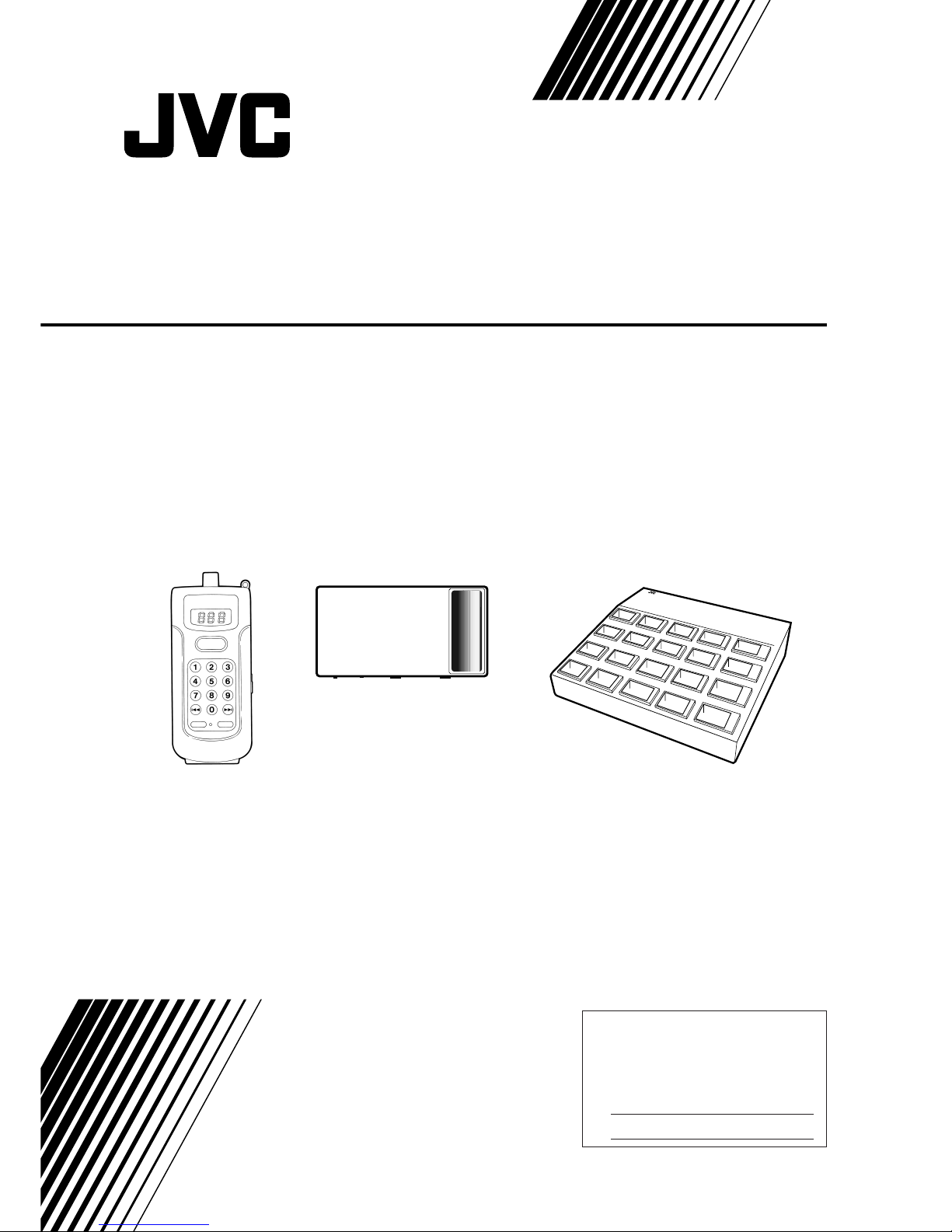
XA-GP1BK Portable ROM Player
XA-GT1TN Infrared Address Transmitter
XA-GC20BK Charger
XA-GP1BK
XA-GT1TN
XA-GC20BK
LVT0278-001A
[J]
For Customer Use:
Enter below the Model No. and Serial
No. which are located either on the rear,
bottom or side of the cabinet. Retain this
information for future reference.
Model No.
Serial No.
INSTRUCTIONS
AUDIO GUIDANCE SYSTEM
Page 2
2
Precautions for Safe Use
Precaution Symbols
Various symbols are located in this manual as well as on the products.
In order for this product to be used safely and correctly, symbols are provided to prevent any damage to the user,
other people, or property. Therefore take the time to understand what the symbols mean before reading this
manual.
DANGER
7 The internal battery pack was made to be used
exclusively with the Portable ROM Player XAGP1BK.
Using the battery pack for any use other than
indicated may destroy, decrease performance, or
shorten the life of the battery. Therefore do not use
the batteries for devices for purposes other than
indicated.
7 Only the XA-GC20BK Charger should be used to
recharge the battery pack.
Using any other recharger than indicated may
result in a fire hazard or device malfunctions.
7 Failure to observe the following in regard to the
battery pack may result in a fire as well as cause
overheating and damage to the unit.
• Do not put in a fire or apply any kind of heat
source to the battery pack.
• Do not place, use, or recharge the battery pack
where the temperature is high, such as near a fire
or heater.
• Do not reverse the positive (+) and negative
(–) polarity and attempt to use the battery.
Also do not carry or store the battery pack with
metal objects such as necklaces or hairpins.
• The positive (+) and negative (–) battery pack
terminals should not come in contact with metal
objects such as a needle.
• Do not puncture with a needle, strike with a
hammer, or step on the battery pack.
• Do not attempt to solder, disassemble, or modify
this product.
7 The battery recharger was made to be used
exclusively with the Portable ROM Player
XA-GP1BK. Therefore do not use the battery
recharger for anything other than the intended
purpose.
Using the battery recharger for any use other than
indicated may result in a fire hazard or electric
shock.
7 Use only power supplies with the indicated voltage.
Failure to do so may result in a fire hazard or
electric shock.
7 Do not attempt to modify the battery recharger in
any way. Interfering with the internal mechanism in
any way may result in a fire hazard or electric
shock.
WARNINGS
7 Stop using the battery pack when there are
abnormal signs such as overheating while
recharging, or a strange smell when the pack has
been stored. Also, the battery pack should not be
used when a change in color and shape or any
other unusual characteristic appears.
7 In the event that liquid from the battery pack enters
the eyes, do not rub the eyes, immediately rinse
with clean water, and receive medical treatment
from a physician as soon as possible. There is the
danger that vision could become impaired.
Also in the event that the leaked battery liquid
comes in contact with the skin or clothes, proceed
by immediately rinsing with clean water. The liquid
may cause a skin rash.
DANGER
Failure to abide by the warnings
that accompany this symbol will
result in improper use of this
product which may result in death
or serious injury. Therefore this
symbol and related instructions
must be followed at all times.
WARNING
Failure to abide by the warnings
that accompany this symbol will
result in improper use of this
product which may result in death
or serious injury.
CAUTION
Failure to abide by the warnings
that accompany this symbol will
result in improper use of this
product which may result in
injury or property damage.
Explanation of the Symbol
Indications
The symbols that alert you to points
of caution.
General Caution
Electric Shock
Symbols that indicate actions that
are prohibited
Prohibited
Disassembling Prohibited
Do Not Touch
Symbols that advise you to
perform a specific action
General Instruction
Pull Out the Plug
Disassembling
Prohibited
Page 3
3
7 When the battery pack that is used in the
XA-GP1BK has been removed, make sure to store it
in a safe place out of the reach of children.
Immediately seek the advice of a medical physician
if the battery liquid is consumed.
7 Recharge the battery pack at a temperature
between 5˚ - 35˚ C (41˚ - 95˚ F).
Do not attempt to recharge the battery pack at a
temperature below or above this range.
Failure to recharge within this range may result in a
decrease in performance, or shorten the life of the
battery pack.
7 Using the unit when smoke, a strange smell, or an
abnormal condition is detected may result in a fire
hazard or electric shock.
Immediately unplug the power cord from the outlet,
confirm that smoke is no longer being produced,
and have your dealer check or service the unit. The
user attempting to service the unit is extremely
dangerous and prohibited.
7 Do not use if there is dust or metallic objects
attached to the power plug (or power adapter)
blades. Failure to clean the plug blades may result
in a fire hazard or electric shock.
7 Do not modify, force to bend, twist, or pull the
power cord. This will damage the cord and may
result in a fire hazard or electric shock.
7 Do not place heavy objects such as furniture on the
power cord and take care not to allow the cord to
become covered. Otherwise the power cord may
be damaged and cause a fire hazard or electric
shock.
7 If the cord does become damaged (the internal
wires are exposed or the cord is cut), a replacement
should be purchased from your dealer. A damaged
power cord may result in a fire hazard or electric
shock.
7 When the unit is dropped or the cover is damaged,
unplug the power cord from the power outlet and
contact your dealer.
Continuing to operate the product under these
conditions may result in a fire hazard or electric
shock.
7 Do not insert metal or combustible objects into the
sockets that are present on the unit. Objects
inserted into the unit may result in a fire hazard or
electric shock.
7 Do not attempt to plug in or unplug the power cord
with wet hands.
Handling the power cord with wet hands may result
in electric shock.
7 Do not touch the power cord during an electrical
storm. Touching the power cord at this time may
result in electric shock.
7 Take precautions to keep the unit dry and to
prevent liquid from entering. In the event that
liquid is spilled into the unit, unplug the power cord
from the power outlet and contact your dealer.
Continuing to operate the product under these
conditions may result in a fire hazard or electric
shock.
7 Use only power supplies with the indicated voltage.
Failure to do so may result in a fire hazard or
electric shock.
7 Do not attempt to modify this product in any way.
Interfering with the internal mechanism may result
in a fire hazard or electric shock.
CAUTIONS
7 The power cord should always be unplugged from
the outlet by grasping the plug (or power adapter)
and never the cord itself. Pulling on the cord itself
will cause damage which may result in a fire hazard
or electric shock.
7 The battery recharger’s power cord should be
located away from all heat sources. Melting of the
cord coating may result in a fire hazard or electric
shock.
7 Make sure to insert the plug (or power adapter)
completely into the power outlet.
Failure to plug in the power cord properly could
cause a short circuit and produce heat that may
lead to a fire hazard or electric shock.
Also avoid using multiple connections where many
plugs are connected to the same extension cord.
7 Do not use a power outlet that does not make a
snug connection with the power cord plug (or
power adapter). Loose and improper connections
will give off heat and may result in a fire hazard.
Contact a dealer or a certified electrician to have the
defective power outlet replaced.
7 Do not place the unit in an excessively moist or
dusty environment.
Operating the recharger in such an environment
may result in a fire hazard or electric shock.
7 Avoid placing the unit near a preparation area in
kitchens or humidifiers. Exposing the unit to soot,
humidity, or dust may result in a fire hazard or
electric shock.
7 The unit should be installed on a level and stable
surface. If the unit is used on an unstable surface,
the unit may fall off, or the entire stand and unit
may fall over causing bodily harm.
7 Confirm that the power cord plug has been
removed from the outlet before attempting to move
the unit. Moving the unit while plugged-in may
damage the power cord and result in a fire hazard
or electric shock.
7 Do not fold the power adaptor in cloth or bedding
or wrap in any way.
Covering or wrapping the adaptor will cause heat to
build up which may cause the case to change shape
and result in a fire hazard.
Therefore, always use the adaptor in an area that is
well ventilated.
Pull Out the
Plug
Pull Out the
Plug
Do Not
Touch
Pull Out the
Plug
Disassembling
Prohibited
Pull Out the
Plug
Page 4
4
7 Handling precautions for the XA-GC20BK Charger
This equipment has been tested and found to
comply with the limits for a Class A digital device,
pursuant to Part 15 of the FCC Rules. These limits
are designed to provide reasonable protection
against harmful interference when the equipment is
operated in a commercial environment. This
equipment generates, uses, and can radiate radio
frequency energy and, if not installed and used in
accordance with the instruction manual, may cause
harmful interference to radio communications.
Operation of this equipment in a residential area is
likely to cause harmful interference in which case
the user will be required to correct the interference
at his own expense.
The included power cord comes equipped with a
Ferrite core which shields against noise. Do not
remove this from the power cord.
7 Install the XA-GC20BK Charger so that the back of
the unit is more than 10 cm from a wall or other
objects.
Without an appropriate amount of space between
the wall and the unit, heat may accumulate and
cause a malfunction.
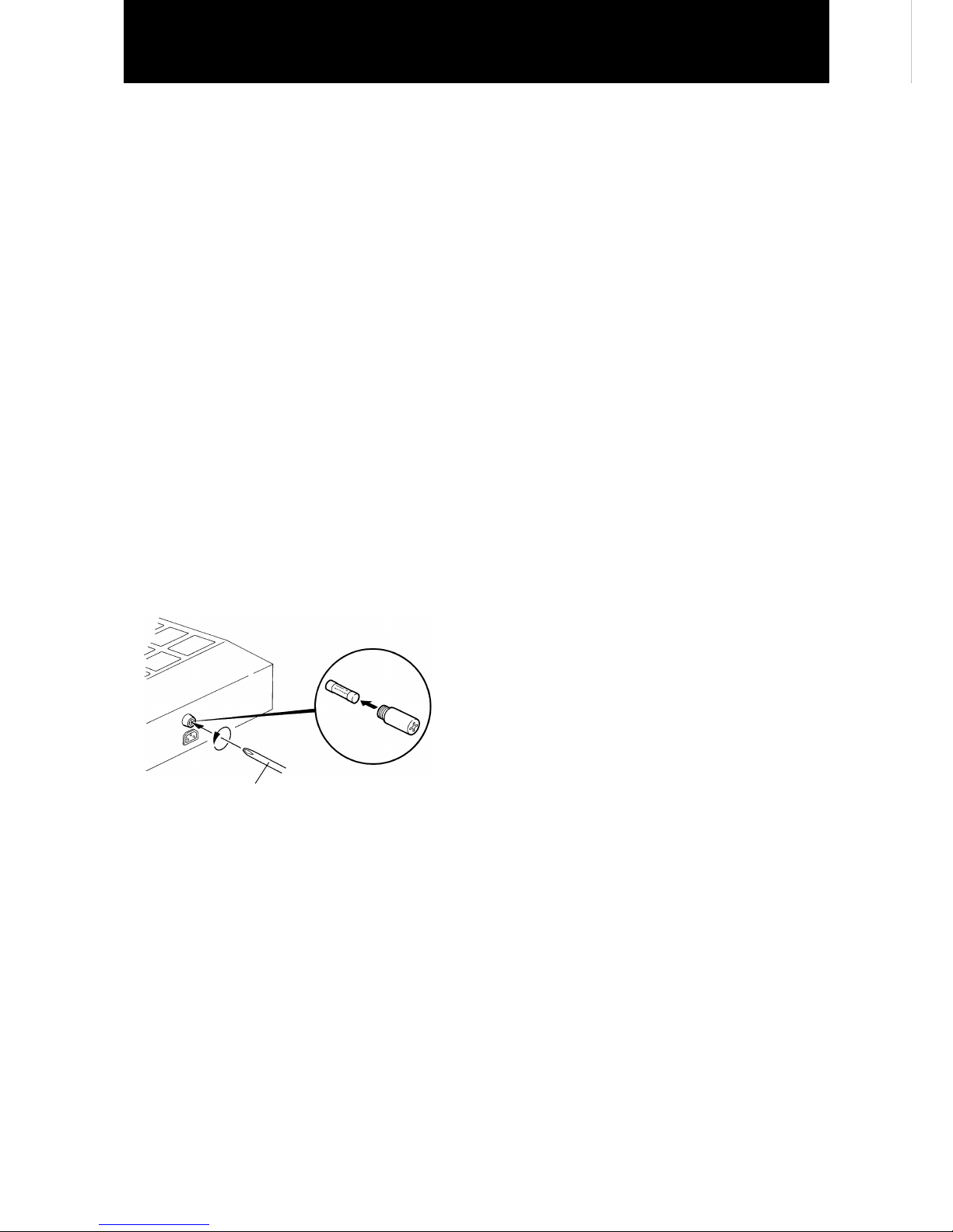
7 Changing the fuse for the XA-GC20BK Charger
The fuse for this product is 250V/5A (Amps).
If the fuse blows soon after replacing, consult with
the dealer where the fuse was purchased. Under
any circumstances do not use a fuse that is above
the indicated amperage of “5A.”
Handling Precautions
Phillips screwdriver
fuse
250V/5A
7 Handling precautions for the XA-GP1BK Portable
ROM Player and the XA-GT1TN Infrared Address
Transmitter
This equipment has been tested and found to
comply with the limits for a Class B digital device,
pursuant to Part 15 of the FCC Rules. These limits
are designed to provide reasonable protection
against harmful interference in a residential
installation. This equipment generates, uses, and
can radiate radio frequency energy and, if not
installed and used in accordance with the
instructions, may cause harmful interference to
radio communications. However, there is no
guarantee that interference will not occur in a
particular installation. If this equipment does cause
harmful interference to radio or television
reception, which can be determined by turning the
equipment off and on, the user is encouraged to try
to correct the interference by one or more of the
following measures:
– Reorient or relocate the receiving antenna.
– Increase the separation between the equipment and
receiver.
– Connect the equipment into an outlet on a circuit
different from that to which the receiver is
connected.
– Consult the dealer or an experienced radio/TV
technician for help.
7 The XA-GP1BK Portable ROM Player is not
waterproof and therefore take the necessary
precautions to avoid exposing the unit to water or
liquids.
In the event that any kind of liquid is spilled into the
unit, turn POWER to OFF and contact your dealer.
7 Using the neck strap
• The XA-GP1BK Portable ROM Player should be
worn around the neck and placed in a position that
can directly receive signals from the Infrared
Address Transmitter. The Auto Play function can
not operate properly if the unit is covered under
clothing.
• When a child is using the Portable ROM Player, to
prevent accidents, replace the neck strap with the
hand strap.
Page 5

5
Part Names and Location ............................................................................................... 6
How to Recharge the Portable ROM Player ................................................................. 7
How to Mount the Infrared Address Transmitter (XA-GT1TN)................................... 8
How to Mount the Infrared Address Transmitter ...................................................... 10
How to Use the Portable ROM Player (XA-GP1BK) ................................................... 16
Methods for Providing Information to Visitors.......................................................... 20
Editing the CF Card Data By Yourself .......................................................................... 21
Maintenance .................................................................................................................. 22
How to Change the Battery Pack ................................................................................ 23
Troubleshooting ............................................................................................................ 24
Specifications ................................................................................................................ 26
Contents
Page 6
6
PLAY
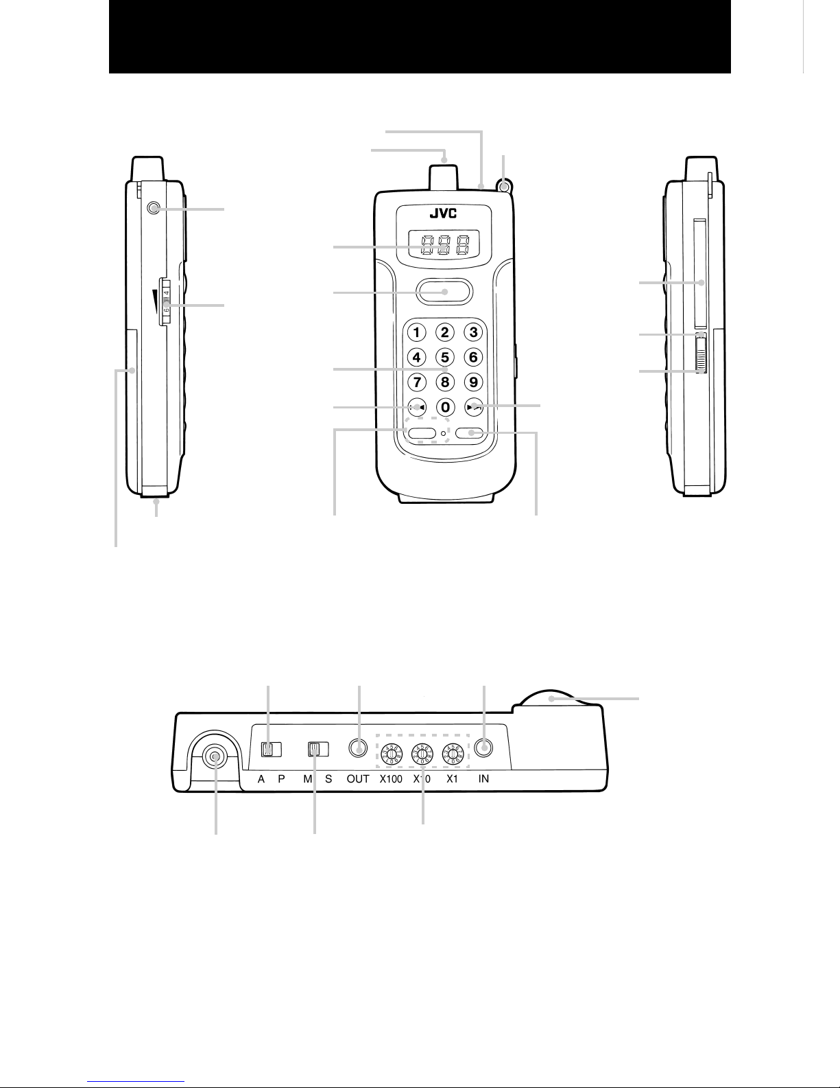
Parts Names and Locations
7 Portable ROM Player (XA-GP1BK)
Optical sensor (Auto)
POWER switch
(page 17)
CF card ejection hole
(page 16)
CF card slot
(page 16)
SLOW button
and indicator light (page 18)
Battery compartment cover
Rechargeable battery terminal
(buttom)
4 key (page 19)
10 key numerical pad
(1 - `) (page 19)
VOLUME dial
(page 17)
PLAY button
(page 18)
Display window
Earphone jack
Hand or neck strap hook (page 16)
Optical sensor (Point)
REPLAY button
(page 18)
7 Infrared Address Transmitter (XA-GT1TN) : Transmitter
Auto/Point switch
(page 8)
Data OUT jack
(page 15)
Data IN jack
(page 15)
DC12V jack
Master/Slave switch
(pages 8, 15)
Address Rotary switch used to set the address (page 8)
Optical
transmission lens
SLOW
¢ key
(page 19)
ON
OFF
POWER
For an explanation of each part,
refer to the page number
REPLAY
˘
Page 7
7
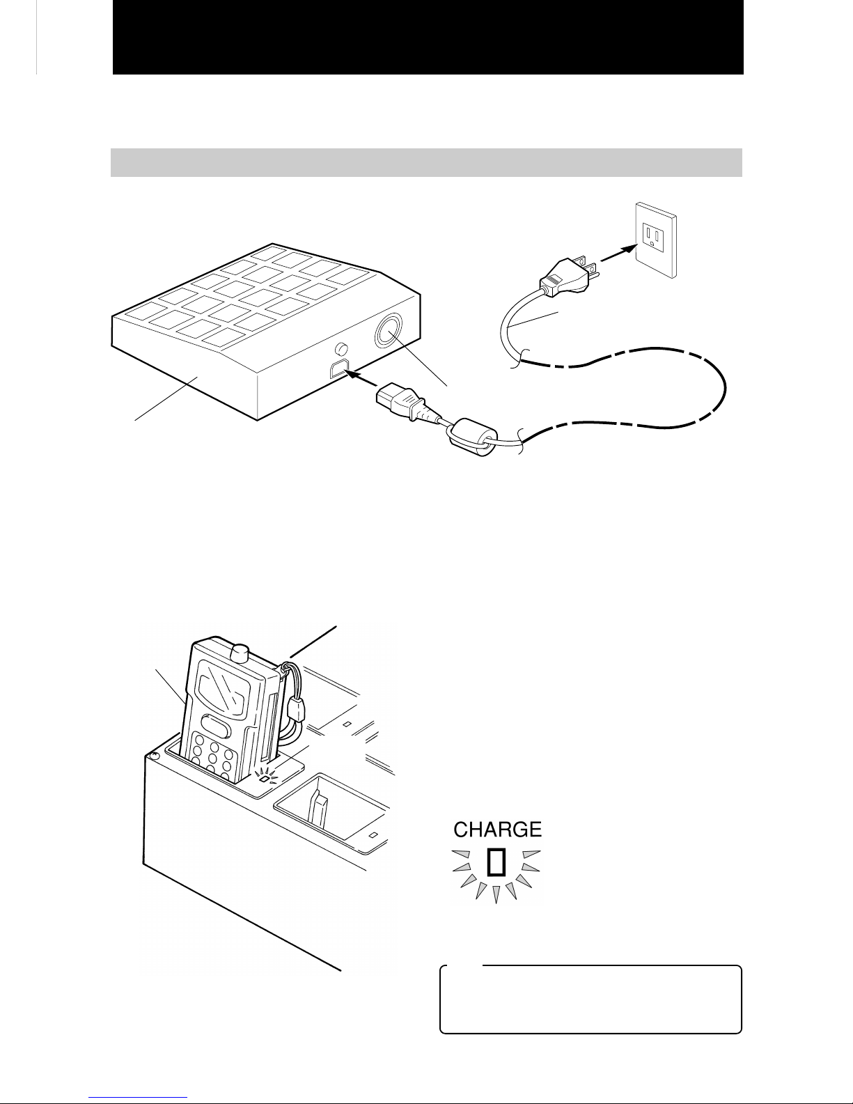
How to Recharge the Portable ROM Player
The portable ROM Player operates on a battery pack which contains rechargeable Lithium ion batteries.
Batteries should be recharged for more than three hours before use.
Charger
(XA-GC20BK)
• There is no power
switch on the
Charger.
• Place on a level and
flat surface.
1 Connect the power cord to the
AC IN jack.
2 Plug the power cord plug into a
standard household power outlet.
AC110-240V
50/60Hz
(Power outlet
that is always
supplied with
a continuous
current.)
Power cord (included with the
Charger)
Only use the indicated power cord.
When power cord is plugged in, the heat
ventilation fan begins to operate.
2
Insert the Portable ROM Player. The display window should be facing towards
you.
• A maximum of 20 units can be recharged at one
time.
The Portable ROM Player should be recharged with
the POWER turned OFF. The amount of time
necessary to recharge the batteries becomes
slightly longer when the POWER is left ON.
• About 3 hours is required to fully recharge the
batteries.
Even when the Portable ROM Player is left in the
recharger, it is not possible for the batteries to
become over charged.
• Recharge indicator
The battery level is indicated by the color of the
light.
Red :Less than 60% of
recharging has taken
place.
Green :The batteries are more
than 60% recharged.
Even when the batteries
become completely
recharged, the indicator
light stays on.
Portable ROM
Player
(XA-GP1BK)
Recharge
indicator
Note
• Take precautions to install the Charger more than
10 cm from a wall or other objects. This assures
that the unit can be adequately cooled during
operation.
How to Recharge the Portable ROM Player
1
Connect the power cord.
Page 8
8
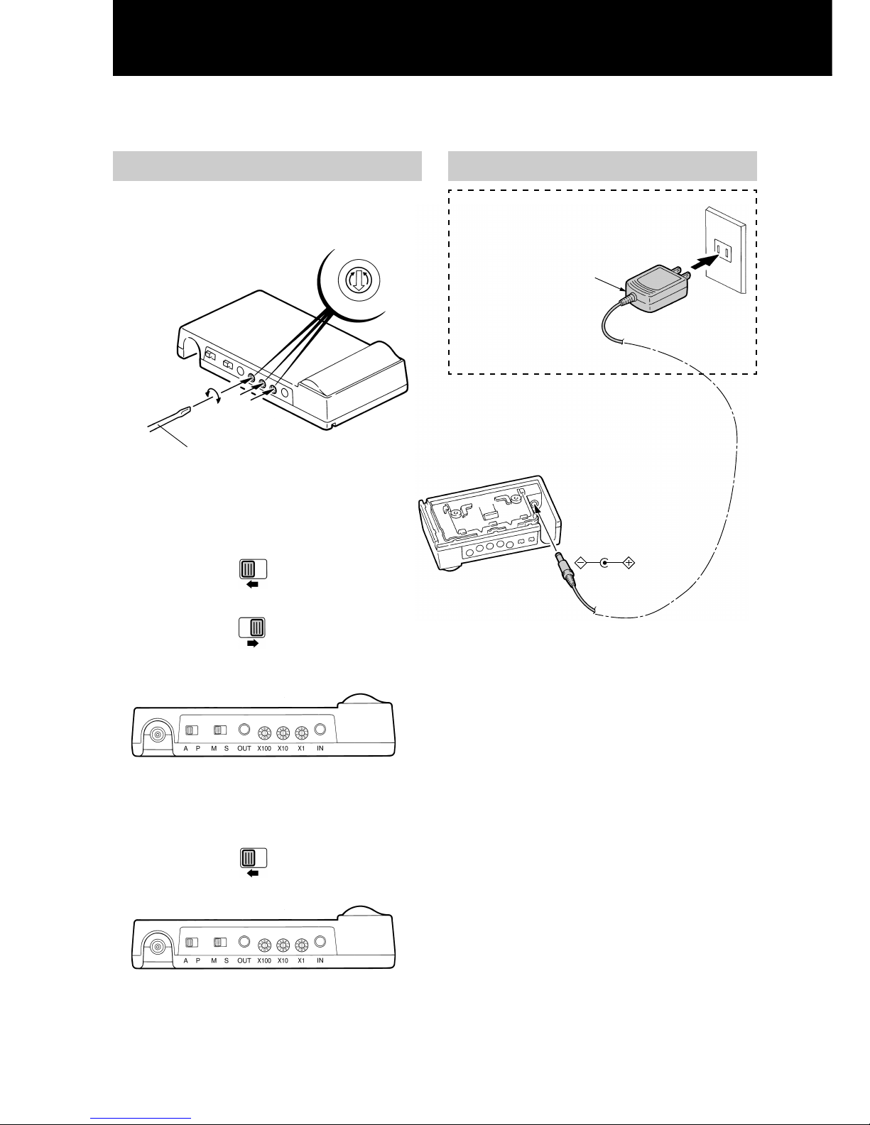
How to Mount the Infrared Address Transmitter (XA-GT1TN)
The Infrared Address Transmitter can be secured to either a cable or a ceiling railing.
Settings for each switch
1
Setting the address
• Set the desired address with the rotary switch.
(000 - 255)
Slotted screwdriver used for clocks
(2 mm diameter - sold separately)
2
Setting the Auto/Point switch
• To enter the Auto
Start mode
• Set the switch to “A”
Auto.
• To enter the
Pointing mode
• Set the switch to “P”
Point
3
Setting the Master/Slave switch
• The switch is now set
to “M” master.
Regarding connections to the power source
Example:
Connect to standard household power
outlet or a ceiling outlet with a safety
plug.
Power adaptor
(sold separately)
Connect to DC12V/0.4A
A P
A P
M S
Page 9

9
Attaching the Cable Clamps (securing the unit to a cable)
• For more information on mounting a ceiling railing,
refer to page 12.
1
Remove the screw
and separate parts
A and B.
2
Secure parts B and
C to the cable with
the screws.
3
Insert metal fixture
A and secure with
the screw.
4
Fit the transmitter
onto the secured
mount.
Clamp segment A
Picture cable
Clamp segment A
Clamp
segment B
Clamp segment C
M3 x 6 mm screws (included)
Use the screw that
was removed in
step 1.
Loosen this screw to adjust
the angle of the transmitter.
• Use the support arms when a twisted cable causes
the tarnsmitter to become unstable.
Push the support arms slightly
towards each other (in the
direction indicated by the
arrows) and pull the support
arms out.
Support arm
z
The support arms support the
transmitter parallel to the exhibit wall.
Clamp segment B
Page 10

10
An Example of the “Pointing” Method.
Ceiling railing
Power outlet or a ceiling outlet with a safety plug
(sold separately)
• The power adaptor is inserted and then
secured by turning. This prevents the
adaptor from falling.
Turn the
adaptor
Optical transmission lens
• When explanation cards are attached to the
transmitter, take precautions not to cover the
optical transmission lens.
7 Installation position
• Position the transmitter close to the picture that will be explained.
• For large size pictures, it is recommended that the visitor be adequately informed as to where the Portable
ROM Player should be pointed.
Example : Instructions for the visitor, such as “Please Point the Portable ROM Player at the name of the
picture and press
PLAY
” can be printed on a card and placed on the transmitter.
7 Adjusting the Angle of the Transmitter
Exhibit wall
Within a range of 2.5 - 3 meters (8.2 - 9.8 ft)
from the ceiling, the transmitter should sit at a
5° angle in a downward direction from the
exhibit wall.
In this range the transmitter can be
basically parallel with the wall.
Within a range of 0 - 0.5 meters (0 - 1.6 ft) from the floor, the transmitter should
sit at a 5° angle in an upward direction from the exhibit wall.
• As illustrated in the diagram
below the transmitter should be
positioned so the switches and
jacks are either up or down
when directly facing the unit.
How to Mount the Infrared Address Transmitter
(continued from page 9)
Page 11

11
7 Transmission Distance
7 Transmission Area
Vertical projection range
Horizontal projection range
7 Selecting a Transmitter
Optical sensor characteristics for
the Portable ROM Player
(16.4 ft)
(23 ft)
(16.4 ft)
(6.6 ft)
(16.4 ft)
(6.6 ft)
(6.6 ft)
Directly facing the transmitter at a distance of 7
meters (23 ft) (When installed in a room, the
transmitter should not be exposed to direct sunlight.)
With the transmitters set up with 2 meter (6.6 ft)
intervals between them, even at a distance of 5
meters (16.4 ft), a transmitter can be easily selected.
When facing the transmitter, signals are sent within a
45° angle from a central axis. “Play” will be easily
activated at a distance of 5 meters (16.4 ft) from the
transmitter.
Range characteristics of the transmitter
Page 12

12
How to Mount the Infrared Address Transmitter
(continued from page 11)
An Example of “Auto Start” Method
• The transmitter should be installed for example at the entrance to the exhibit, in the path of the visitor.
Ceiling railing
Suspended hook
Mounting fixtures A and B
(included)
M10 x 20 mm bolt (included)
Turn the
adaptor
Power outlet or a ceiling outlet with a safety plug.
(sold separately)
• The power adaptor is inserted and then
secured by turning. This prevents the
adaptor from falling.
Portable ROM Player
service counter
7 Installation position
approximately 15°
• Install the transmitter in a place where the visitors
will pass and will be facing in one direction.
• The transmitter should be positioned along the
exhibit course at about a 15° angle in the opposite
direction in which the visitors move.
Note
It is possible that under certain conditions, the Auto
Start method will fail to operate. Therefore it is not
advisable to use this system to inform the visitor of
emergency exits or any other life-saving information
that is necessary during an emergency.
Exhibit
Course
Entrance
Page 13

13
7 Transmission Distance
Note
When an “Auto” signal is received during “Point”
playback, the Portable ROM Player will
automatically switch to the “Auto” playback.
For this reason, provide as much space as possible
between the Point and Auto transmitters.
Projection area
Range characteristics of the transmitter
Optical sensor characteristics for the Portable ROM Player
(6.6 ft)
(9.8 ft)
(9.8 ft)
(16.4 ft)
Horizontal projection range
Directly below the transmitter at a distance of 5
meters (16.4 ft) (When installed in a room, the
transmitter should not be exposed to direct sunlight.)
Forwards and
backwards projection
range
Page 14

14
How to Mount the Infrared Address Transmitter
(continued from page 13)
When transmitting the same address data to a larger area, multiple XA-GT1TN can be connected to operate
together.
Connecting Multiple Infrared Address Transmitters
• When displaying a three-dimensional exhibit and a
wider area needs to be covered by the Audio
Guidance System, multiple XA-GT1TN Infrared
Address Transmitters can be connected to operate
together. To accomplish this setup, one transmitter
is set as the “master” and the other transmitters are
set as “slaves.” All of the address data that is set
for the master will be transmitted from all of the
slaves as well.
• As seen in the exhibit illustrated in the diagram,
only one visitor facing the work of art can receive
the playback information. However, by connecting
four XA-GT1TN transmitters in a master/slave
relationship, the visitor can listen to the playback at
different points surrounding the exhibit.
• Each transmitter’s Auto/Point switch, should be set
to “P” point.
• Connect the power adaptor to each transmitter.
• A maximum of five XA-GT1TN units can be
connected.
Exhibit stand
Explanation card
• In the diagram below, data is transmitted from a
“master” transmitter to the linked “slave”
transmitters in sequence. The procedure for setting
up this type of master/slave connection is described
on the following page.
XA-GT1TN transmitter acting as a slave.
XA-GT1TN
transmitter
acting as
master.
XA-GT1TN transmitter acting as a slave.
XA-GT1TN
transmitter
acting as a
slave.
(Aerial view of the exhibit)
• An example of the “Pointing Method”
A P
Exhibit stand
Page 15

15
• How to Make Connections
Use the indicated connection cord:
∅ 3.5 mini jack length: 2 meters (6.6 ft) (sold separately)
Use the indicated
connection cord:
∅ 3.5 mini jack length:
2 meters (6.6 ft)
(sold separately)
Connect
to OUT
Connect
to OUT
Connect
to IN
Connect
to OUT
Connect
to IN
Master
XA-GT1TN
Slave
XA-GT1TN
Slave
XA-GT1TN
This transmitter’s Master/Slave switch
is set to “M” master.
The second transmitter’s Master/Slave switch and all others
(up to the fifth transmitter) is set to “S” slave.
< Notice >
• The power adaptor must be connected for every transmitter.
• Setting the Auto Start method for multiple transmitters:
While referring to the above explanation “How to Make Connections,” connect the transmitters accordingly.
In this setup, the Auto/Point switch is set to “A.”
This enables the Audio System to provide information to a larger area.
M S
M S
M S
A P
Page 16

16
How to Use the Portable ROM Player (XA-GP1BK)
To prevent any accidents such as dropping the Portable ROM PLayer, it is recommended that the included hand
or neck strap be attached before use.
Hand strap or neck
strap (both are
included)
Cutout groove
Attaching the hand or neck strap Inserting and ejecting the CF card
• To prevent any
accidents such as
dropping the Portable
ROM Player, please
attach the hand or neck
strap.
• Adjusting the length of the neck strap
1 While pushing down...
2 Pull in this
direction to
shorten the strap.
• Inserting the card
CF card (sold separately)
• With the surface that has a cutout groove facing up,
insert the card into the slot. (The card cannot be
inserted upside down.)
• Ejecting the card
1
Turn the POWER to OFF.
2
Push a screwdriver (2 mm diameter)
into the CF card ejection hole.
• Slotted screwdriver used for watches
Push a screwdriver (2 mm diameter) or similar tool
into the hole and the CF card will come out.
Page 17

17
Portable ROM Player
∅ 3.5 mini jack
2
Clamp the earphone over the ear.
• Initialization
When the power is turned on, the following screens
appear in the display window:
Earphone (sold separately)
Using the earphone
1
Insert the earphone (sold separately)
mini plug into the earphone jack
located on the Portable ROM Player.
VOLUME dial
3
Adjust the volume to a comfortable
level.
• Sound is still produced even
if the VOLUME dial is set to
“MIN” minimum.
How to turn on the power
• Set the POWER
switch to ON.
The initialization
screen appears in
the display
window. After
about 5 seconds,
the unit enters
stand by.
software version
display
• When a CF card has not been
inserted, the screen display stops
here.
remaining battery
power display
CF card version display
• When turned on within an Auto
reception area, playback begins
without displaying the CF card
version.
stand-by display
• At this point, the unit is in stand by.
* The remaining battery power display will differ according
to the power remaining in the rechargeable batteries.
Displayed when the battery power is
approximately more than 75% :
Displayed when the battery power is
approximately between 50 - 75% :
Displayed when the battery power is
approximately between 30 - 50% :
Displayed when the battery power is
approximately below 30% :
Example:
Example:
Example:
Displayed when
version 1.2 is
installed
Displayed when the
battery power is
approximately more
than 75%.
Page 18

18
How to Use the Portable ROM Player (continued from page 17)
Playback starts through reception of encoded infrared signals or by inputting commands with the numerical
keys.
Playback through the reception of encoded infrared signals
There are two types of playback available: “Point reception” which operates in close proximity to the exhibited
work of art, and “Auto reception” which operates automatically when the Portable ROM Player enters an area of
reception.
• Starting playback through Point
reception. (Pointing method)
1
Point the extended pointer on top of
the Portable ROM Player at the
Infrared Address Transmitter.
• For information on the signal transmission
distance, refer to Transmission Area on page 11.
• The encoded infrared signals
are received and when a “Point
message” is present, playback
will start. When playback does
not start, move closer to the
Infrared Address Transmitter
and push
PLAY
once more.
• Starting playback through Auto
reception. (Auto Start method)
1
Enter the transmission area that has
been set for Auto transmission while
holding the Portable ROM Player.
• For information on the signal transmission
distance, refer to Transmission Area on page 13.
Encoded infrared signals are received
2
When an “Auto message” is present,
playback will start automatically.
< Notice >
• Under the following conditions, playback will NOT
start:
When the Portable ROM Player is receiving the
same encoded infrared signal again.
(However, if you exit the transmission area for 2
minutes and then return, playback will start.)
• Replay the message
• Playback at a slower speed
• Press the SLOW button when
listening to information that is
in a foreign language or for
any other reason you may
want to slow down playback.
The indicator light turns on and
the message is played back
slowly from the beginning.
Press the SLOW button once
more to return to the normal
speed. However when the
playback file uses the µ-Law
algorithm, the “SLOW”
function will not operate.
Light turns on.
REPLAY
PLAY
SLOW
2
Press
PLAY
.
What to do when the message is too fast or needs to be repeated ?
• Press the REPLAY button
to listen once more to the
message that is indicated
by the number in the
display window. Press the
REPLAY button during
playback to listen to the
message from the
beginning.
Page 19

19
Playback with the 10 numerical keys
• Playback can also be controlled with
the 10 numerical keys.
1
Input the address number using the
10 numerical keys.
• Input the desired number to input the three-digit
number.
Example: To input the address number “001,”
press key 1.
2
Press
PLAY
\ Playback begins.
• You can also playback the message by merely
pressing the REPLAY button.
Note:
• If an unregistered address number is entered,
playback cannot begin.
• To stop playback at any time during the message,
press
PLAY
. To listen to the message once more,
repeat steps 1 and 2.
The entered
number blinks.
The entered
number stays lit.
Playback is possible even when an Infrared Address Transmitter has not been installed.
Playback is possible by entering an address number directly.
• Playback with , keys.
1
Press the or key to display
the desired address number.
Example : When you want to listen
to address number 003.
The address
number
blinks.
Each time this
key is
pressed, the
unit moves to
the previous
number.
Each time this key is
pressed, the unit
moves to the next
number.
2
Press
PLAY
\ Playback begins.
The selected
number stays lit.
• You can also playback the message by merely
pressing the REPLAY button.
• To stop playback at any time during the message,
press
PLAY
. To listen to the message once more,
repeat steps 1 and 2.
• When an address number is entered that does not
exist, the unit returns to stand by and
(- - -) is displayed. Or the unit returns to the
previous address number.
• When
PLAY
is not pressed within 5 seconds of
selecting an address number, the unit returns to
stand by (- - - ) or returns to the previous address
number. To reenter the desired address number,
start from step 1.
• When the
, , or the numerical keys are
pressed, numbers that have not been assigned an
address will be skipped. This allows you to do a
“search” for the next assigned message each time
you press the key.
• When
PLAY
is not pressed within 5 seconds of
selecting an address number, the unit returns to
stand by (- - - ) or returns to the previous address
number. To reenter the desired address number,
start from step 1.
1
PLAY
¢
4
PLAY
Within 5
seconds...
Within 5
seconds...
Page 20

20
Points to remember when the visitor
receives the Portable ROM Player
• Turn the POWER to ON and confirm the following
points when handing the Portable ROM Player to
the visitor.
1
Check the remaining battery power.
• The visitor should receive the unit when
(or ) is displayed.
(If there is less power than indicated above, “No
Battery Power” may occur during the exhibit.)
2
Check the CF card.
• Confirm that the CF card is what the visitor
requested and that the card has been inserted.
Also check the card version in the display
window.
3
Check the earphone.
• Confirm that sound is properly produced from
the earphone.
< Notice >
• It is recommended that earphones are replaced
regularly. Especially after extended periods of
use, the wire at the base of the plug often
becomes cut. Therefore make sure that the
earphones are properly working.
• Earphones should always be cleaned and
replaced regularly in order to maintain public
standards of personal hygiene.
• When a child is using the Portable ROM Player, to
prevent accidents, replace the neck strap with the
hand strap.
Points to remember when the visitor
returns the Portable ROM Player
• Confirm the following points when the visitor has
finished viewing the exhibit and returns the
Portable ROM Player.
1
It is recommended that the following
is said to the visitor when the
Portable ROM Player is returned;
“Thank you very much for visiting our
exhibit today. Were there any difficulties
with the Portable ROM Player?”
• In the event that the visitor did have some
problems, leave the CF card inserted, hand the
Player to the Audio Guidance System
administrator, and explain the problem.
Example: The visitor was not able to hear the
explanation for exhibit number XX in
exhibit hall number XX.
2
Check that the CF card is still inserted.
•
In the event that the card is missing, immediately
request that the visitor return the card.
3
Turn POWER to OFF.
•
This will extend the life of the batteries.
It is recommended that the batteries are returned
to the recharger for recharging.
Methods for Providing Information to Visitors
Page 21

21
Editing the CF Card Data By Yourself
The Audio System administrator should refer to information below when editing (authoring) the CF card data.
CF Card Format
• The CF card is in DOS format.
(When the CF card is purchased it is already in DOS
format. Do not alter the version, cluster size, or
make any other physical format change.)
Long file names are incompatible and therefore
cannot be used.
• Store the message file in the sub directory
“01??????” of the root directory.
In the “01” section, a number can be set from 01 -
09.
(The default setting is 01.)
For more information on editing methods for
playback that is initiated from the sub directory,
refer to Message Group Select Functions on this
page.
The area occupied by “??...” can be used after
assigning a desired value.
Naming a Message File
Name a file according to the following instructions.
Point reception file Auto reception file
P001????. WAV A101????. WAV
• The “P” prefix indicates the message will be played
back through the point reception method. The Auto
reception method is indicated with “A.”
• The 2nd to 4th digits can be used to indicate an
address number from 000 - 999.
However, Point or automatic playback that is
initiated from the reception of encoded infrared
signals, can only be assigned to the address
numbers 000 - 255.
The address numbers from 256 - 999 can only be
used for playback that is initiated through key entry.
For these numbers, “P” should be assigned as the
prefix.
• Do not assign the same address number for Point
reception and Auto reception messages.
• The 5th to 8th digits can be used after assigning a
desired value. The file extension should always be
designated as “WAV.”
< Notice >
• Make sure to use only the CF card recommended by
JVC.
• Presently JVC is introducing CF card authoring
specialists to our customers. For more information,
please feel free to contact a sales representative.
File That Displays the CF Card
Version
Through placing a file that displays the CF card
version in the root directory, after turning on the
power, the CF card version will be displayed. This will
appear after the display that indicates the remaining
amount of battery power. This function makes it
possible to distinguish between the contents of one
CF card and another. When a file that displays the CF
card is not present, the version number is not
displayed.
• File name
The file name for the file that displays the version
should be “VER.TXT.”
• File format
The following explains the format for the file that
displays the card version.
• Write a file prefix that indicates a version number
from 00 - 99.
• Display format
The CF card version will appear in the display
window as “C01.” The number “01” will change
according to the version number written in the file
that displays the card version.
Message Group Select Function
It is possible for the visitor to select from a variety of
messages that can be played back. This is
accomplished because a number of sub directories
can be created and in each sub directory different
languages or additional message files can be stored.
• Sub directory names
There are 9 different types of subdirectories from
“01??????” to “09??????.”
The area occupied by “?” can be used after
assigning a desired value.
(The default setting is “01??????.”)
• Selection method for the message group (language)
A sub directory can be selected by turning the
POWER ON while pressing one of the 10 numerical
keys 1-9. If POWER is turned ON without pressing
any of the 10 numerical keys, “01??????” is
selected.
• Checking the message group (language)
Check with the earphones whether or not the
playback correctly corresponds to the selected
message group.
Page 22

22
Maintenance
Portable ROM Player Cotton swab
Cleaning the Rechargeable Battery Terminals
• The terminals should be cleaned about once a month. If the terminals are
not cleaned regularly, it is possible that debris will hinder recharging.
• The Portable ROM Player should only be cleaned with a dry and soft
cloth. Make sure that the optical sensor lens is kept completely clean.
Charger
Rechargeable battery terminal
Cotton swab
Charger terminal
Page 23

23
How to Change the Battery Pack
How to Change the Battery Pack
Although the life of the battery pack will vary according to the amount of use, the average is about 2 years. When
the battery pack can only supply power for an extremely short period of time even after recharging, the pack
should be replaced. The battery pack should be discarded and replaced with a new one.
1
Open the battery cover
on back of the Portable
ROM Player.
2
Take out the battery
pack.
3
Replace the old battery
pack with a new one
and put back the cover.
Insert the battery with the
inscription facing upwards.
• Close the cover and recharge
the new battery pack for more
than 3 hours.
Battery pack
(BN-R368)
• The battery pack (BN-R368) is
sold separately.
Page 24

24
Problem Possible Cause Solution
Troubleshooting ––
Problem? Malfunction?
If problems arise, first try these suggestions before having the
unit serviced.
• POWER is not turned ON.
• When POWER is turned ON,
the display window stays fixed
on the display .
• The display window stays fixed
on a number display such as
.
• The display window stays fixed
on the error display
.
• The internal battery pack has
not been recharged.
• The battery pack is about 2
years old and should be
replaced.
• POWER is not turned ON.
• Master/Slave switch is not
switched to “M” master .
• Auto/Point switch is not set
properly.
• Address number is not
properly set.
• The exhibit card is covering the
optical transmission lens.
• Turn POWER switch to ON.
• There is a problem with the
internal program of the main
unit.
Contact a JVC service
representative.
• Take out the CF card and insert
again.
If this does not resolve the
problem, contact a JVC service
representative.
• The CF card has malfunctioned.
Replace with a CF card that
functions properly.
• Recharge the Portable ROM
Player with the recommended
chager.
• Purchase a new battery pack
(BN-R368) at your local dealer.
• Plug the power adaptor into a
power outlet.
• Switch to “M” master.
• When using the Pointing
method:
• When using the Auto method:
• Set the correct 3 digit address
number using the Address
Rotary switch.
• Place the card so that the
optical transmission lens is
visible.
set the switch to
“P” point.
set the switch to
“A” Auto.
Does not operate.
Even after
recharging, within
a short time the
unit cannot be
used.
Does not operate.
Checking the Portable ROM Player
Checking the Infrared Address Transmitter
Reference
page
page 17
page 7
page 23
page 8
page 8
page 8
page 8
page 10
M S
A P
A P
Page 25

25
Problem Possible Cause Solution
• Optical transmission lens on the
transmitter or the sensor lens on
the Portable ROM Player is dirty.
• Extremely strong rays or natural
sunlight shining in the direction
of the Portable ROM Player are
interfering with sensor
reception.
• An invertor fluorescent light has
been placed too close to the
transmitter and is shining in the
direction of the Portable ROM
Player.
• Installation angle of the
transmitter has slipped or was
not set properly.
• The set address and the CF card
WAV file do not match.
• Wrong CF card was inserted.
• Power cord is not plugged in
properly.
• Portable ROM Player and
charger terminals are dirty.
• Fuse has blown.
• Clean the optical
transmission lens on the
transmitter or the sensor
lens on the Portable ROM
Player.
• Place a blind to cover the
region of the window where
the sunlight enters.
• Place the transmitter away
from that type of fluorescent
light. Or replace the light
with a more common type of
fluorescent light.
• Install the transmitter
correctly after referring to
the examples that illustrate
the Pointing method and the
Auto method.
• Set the correct address.
• Insert the correct CF card.
• Plug the power cord
completely into the outlet.
• Clean both terminals used
for recharging.
• Replace the fuse with a new
one.
(Use 250V/5A fuse.)
The infrared beam
projection range is
extremely short.
Transmission area
is too small.
Does not operate.
Checking the
CF card
Charger
Reference
page
page 10
|
page 13
page 7
page 22
page 5
Cannot recharge
the Portable ROM
Player.
Checking the Infrared Address Transmitter
Note
• JVC is not responsible for any lost revenues or
damages incurred due to the improper operation or
malfunctioning of these products. This should be
fully understood in advance before attempting to
use these products.
• Many of the functions of the Portable ROM Player
are executed with the use of micro processors. In
the event that the unit does not operate properly
due to for example static electricity, turn the POWER
to OFF. Then after a short while, turn back to ON.
Page 26

26
Specifications
In order to improve products, the specifications below and
the external design are subject to change without notice.
Portable ROM Player (XA-GP1BK)
Recording medium Flash memory card
(CF card)
Sampling wave 8 kHz
frequency
Sound data TrueSpeech 8.5
compression (8.5 kbps)
algorithm µ-Law (64 kbps)
Data rate Approx. 1 kilobyte/s
Playback time Approx. 30 minutes per
2 MB
when using TrueSpeech
8.5
Maximum numbers 1000
of messages
Power DC 3.6 V (uses
rechargeable Lithium ion
batteries BN-R368)
Battery power 6 hours for continuous play
duration
12 hours for intermittent play*
(* Assuming 30% of total
operation time is active
playback)
Output jack Earphones
(monaural mini, ∅ 3.5)
Dimensions
58.6 (W) x 141.4 (H) x 23.5 (D) mm
(2-3/8” x 5-5/8” x 1”)
Mass Approx. 165 g (0.37 lbs.)
(with battery pack)
Provided Accessories
• Hand strap ............................................................... x 1
• Neck strap................................................................ x 1
Charger (XA-GC20BK)
Maximum number of 20 (XA-GP1BK)
units that can be
recharged
Recharging time Approx. 3 hrs.
(when fully recharged)
Power consumption 270 VA (when charged)
Power supply AC 110-240 V, 50/60 Hz
Dimensions
477 (W) x 138 (H) x 438 (D) mm
(18-13/16” x 5-7/16” x 17-1/4”)
Mass Approx. 7.5 kg (16.6 lbs.)
Provided Accessories
Power cord (includes Ferrite core)............................ x 1
Infrared Address Transmitter
(XA-GT1TN)
Transmission method JVC Infrared Encoding
Address Transmitter
Address settings Mini rotary switch x 3
(Code No. 000 ~ 255)
Directional angle Horizontal direction:
Approx. ±20°
(when set to Auto)
Approx. ±45°
(when set to Point)
Vertical direction:
Approx. ±20°
Transmission distance Approx. 7 m (23 ft)
(depending on hall
conditions)
Power source DC 12V ±10%, 0.4 A
(stabilized power)
Dimensions
120.5 (W) x 28 (H) x 66 (D) mm
(4-13/16” x 1-1/8” x 2-5/8”)
Mass Approx. 110 g (0.25 lbs.)
Provided Accessories
• Metal fixture mount................................................ x 1
• Screw (M3 x 6 mm)................................................. x 2
• Bolt (M10 x 20 mm) ................................................ x 1
Additional Accessories (sold separately)
• Memory card (CF card)
• Earphones (monaural mini, ear clamp type)
• Rechargeable Lithium ion battery : BN-R368
• Master/Slave connection cord (∅ 3.5 mini plug
included) length 2 m (6.6 ft).
Page 27

VICTOR COMPANY OF JAPAN, LIMITED
JVC
EN
Printed in Japan
0199IMMWSTSAN
XA-GP1BK/XA-GT1TN
XA-GC20BK
AUDIO GUIDANCE SYSTEM
 Loading...