

Page 1
SERVICE MANUAL
DIGITAL AUDIO PLAYER
XC03020053
XA-A50CL-J/E/N
Model No.
TABLE OF CONTENTS
1 SPECIFIC SERVICE INSTRUCTIONS . . . . . . . . . . . . . . . . . . . . . . . . . . . . . . . . . . . . . . . . . . . . . . . . . . . . . . 1-3
2 DISASSEMBLY . . . . . . . . . . . . . . . . . . . . . . . . . . . . . . . . . . . . . . . . . . . . . . . . . . . . . . . . . . . . . . . . . . . . . . . 1-4
3 TROUBLESHOOTING . . . . . . . . . . . . . . . . . . . . . . . . . . . . . . . . . . . . . . . . . . . . . . . . . . . . . . . . . . . . . . . . . . 1-5
COPYRIGHT © 2005 Victor Company of Japan, Limited
No.XC030
2005/3
Page 2
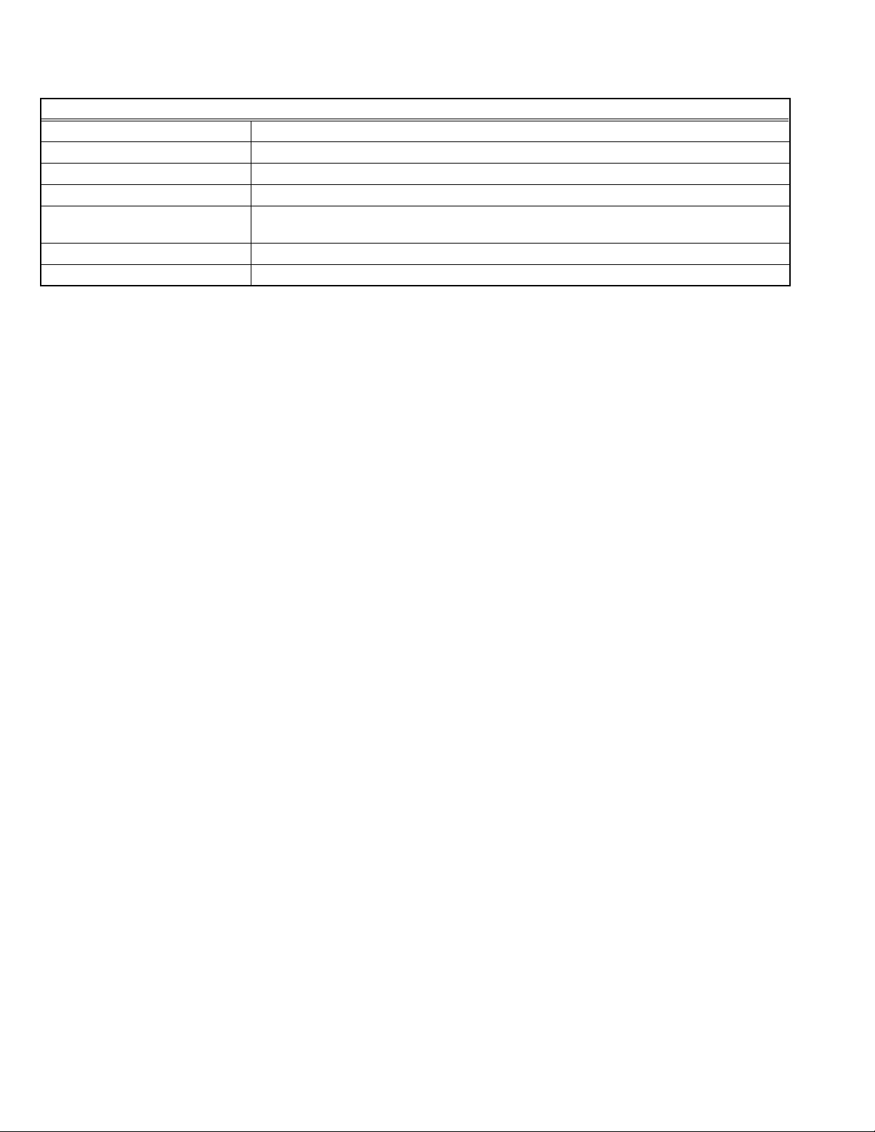
SPECIFICATION
XA-A50CL-J/E/N
Memory type 128 MB Flash memory
Playable files MP3, WMA, WMA-DRM (copyright-protected)
Headphones driver unit 30 mm diameter Neodymium
Power supply AAA alkaline battery (DC 1.5 V) x 1
Battery life approx. 20 hours (Playback of MP3 files created at 64 kbps/22 kHz with LED setting set to off.
0.1mW+0.1mW output)
Cord length 0.5 m (19-11/16 inch)
Mass 57 g (2.01 oz) (incl. an alkaline battery)
Design and specifications subject to change without notice.
1-2 (No.XC030)
Page 3

SECTION 1
SPECIFIC SERVICE INSTRUCTIONS
This model is a specification that automatically deletes the music file preserved in an internal memory when connecting it with the
terminal USB of PC.
Please connect the main body with PC according to the following procedure before the repair begins When you back up the music file.
(1) The main body is connected with the terminal USB of PC.
(Please do with Windows Me, 2000, and XP.)
(2) When LED starts blinking, the button is pushed quickly in order of MODE → vol+ → vol- → → → PLAY.
The interval when each button is pushed is pushed within one second.
(3) Please do over again from one again without pushing the last PLAY button when it pushes, it makes a mistake in the button or
it fails.
PC is recognized as a removal drive without deleting the file preserved in an internal memory.
(No.XC030)1-3
Page 4

2.1 Disassembly method
SECTION 2
DISASSEMBLY
Ear pad
Connector
Battery terminal "-"
Unit case-R
Right drive unit
Wire (Yellow)
Wire (White)
Hook (b)
Wire (Black)
Wire (Green)
Hook (a)
(B)
Hook (b)
(C)
Main board
Switch board
Hook (a)
Left drive unit
(A)
(A)
Top case-L
Battery cover
2.1.1 Removing the left drive unit
(1) Remove the battery cover.
(2) Remove the three screws (A) attaching the top case-L.
(3) Pull out the battery terminal "-".
(4) The solder of two wires connected with the left drive unit is removed.
(5) The hook (a) two places are removed, and the left drive unit is removed.
2.1.2 Removing the right drive unit and each board.
(1) Remove the ear pad
(2) Remove the two screws (B) attaching the unit case-R.
(3) Disconnect the connector on the main board.
(4) The solder of two wires connected with the right drive unit is removed.
(5) The hook (b) two places are removed, and the right drive unit is removed.
(6) Remove the two screws (C) attaching the main board, and the main board and switch board are removed.
1-4 (No.XC030)
Page 5

SECTION 3
TROUBLESHOOTING
3.1 Cannot the sound not be emitted or the playback operation be done.
(1) First of all, please do the following check.
• It confirms whether the wire breaks has been all(White,Yellow,Red,Brown).
Confirm the energization by attaching a tester to each wire of the soldered parts on the left drive unit and the main board connector terminal on the right drive unit.
Attach the tester to each wire in the corresponding color; when one end of the tester is attached to the yellow wire in the left
drive unit, the other end should be attached to the corresponding part of the connector terminal on the right drive unit.
• correctly soldered ?
When the wire breaks is found, the wires are exchanged.
(2) If the wire has not been breaks, the main board are exchanged.
(3) Please exchange the switch board when it is not improved even if the main board is exchanged.
(4) Still, please replace the drive unit when it is not improved.
3.2 For connection of wire
Please connect it correctly noting the color of the wire when you connect the wire.
Battery terminal "-" : BrownBattery terminal "+" : Red
Yellow White
Left drive unit
* For arrangement of wire of left drive unit
Please put each wire collectively on the soldering part of the driver unit as shown in the photograph.
When each wire is made asunder or the wire is put on the other side of the driver unit (upper part of the photograph), the noise might
be generated during playback.
Black Green
Right drive unit
(No.XC030)1-5
Page 6

Victor Company of Japan, Limited
AV & MULTIMEDIA COMPANY ACCESSORIES CATEGORY 1644, Shimotsuruma, Yamato, Kanagawa 242-8514, Japan
(No.XC030)
Printed in Japan
VPT
 Loading...