

Page 1

OUTDOOR HOUSING
WB-1540U
WB-1550U
INSTRUCTIONS
(B)
WB-1550U only
DEUTSCHFRANÇAISESPAÑOLITALIANO ENGLISH
For Customer Use:
Enter below the Serial No. which is located on
the body.
Retain this information for future reference.
Model No. WB-1540U/WB-1550U
Serial No.
LST0267-001C
Page 2

These are general IMPORTANT SAFEGUARDS and certain items may not apply to all appliances.
IMPORTANT SAFEGUARDS
1. Read all of these instructions.
2. Save these instructions for later use.
3. All warnings on the product and in the operating instructions should be adhered to.
4. Unplug this appliance system from the wall outlet before cleaning.Do not use liquid cleaners or aerosol cleaners.Use a damp cloth for cleaning.
5. Do not use attachments not recommended by the appliance manufacturer as they may cause hazards.
6. Do not use this appliance near water - for example, near a bathtub, washbowl, kitchen sink, or laundry tub, in a wet basement, or near a
swimming pool, etc.
7. Do not place this appliance on an unstable cart, stand, or table. The appliance may fall, causing serious injury to a
child or adult, and serious damage to the appliance may fall, causing serious injury to a child or adult, and serious
damage to the appliance.
Use only with a cart or stand recommended by the manufacturer, or sold with the appliance. Wall or shelf mounting
should follow the manufacturer’s instructions, and should use a mounting kit approved by the manufacturer.
An appliance and cart combination should be moved with care. Quick stops, excessive force, and uneven surfaces
may cause the appliance and cart combination to overturn.
8. Slots and openings in the cabinet and the back or bottom are provided for ventilation, and to insure reliable operation
of the appliance and to protect it from overheating,these openings must not be blocked or covered. The openings
should never be blocked by placing the appliance on a bed, sofa, rug, or other similar surface. This appliance should
never be placed near or over a radiator or heat register. This appliance should not be placed in a built-in installation such as a bookcase unless
proper ventilation is provided.
9. This appliance should be operated only from the type of power source indicated on the marking label. If you are not sure of the type of power
supplied to your home, consult your dealer or local power company. For appliance designed to operate from battery power, refer to the operating
instructions.
10. For added protection for this product during a lightning storm, or when it is left unattended and unused for long periods of time, unplug it from
the wall outlet and disconnect the antenna or cable system. This will prevent damage to the product due to lightning and power-line surges.
11. Do not allow anything to rest on the power cord. Do not locate this appliance where the cord will be abused by persons walking on it.
12. Follow all warnings and instructions marked on the appliance.
13. Do not overload wall outlets and extension cords as this can result in fire or electric shock.
14. Never push objects of any kind into his appliance through cabinet slots as they mat touch dangerous voltage points or short out parts that
could result in a fire or electric shock. Never spill liquid of any kind on the appliance.
15. Do not attempt to service this appliance yourself as opening or removing covers may expose you to dangerous voltage or other hazards.
Refer all servicing to qualified service personnel.
16. Unplug his appliance from the wall outlet and refer servicing to qualified service personnel under following conditions:
a. When the power cord or plug is damaged or frayed.
b. If liquid has been spilled into the appliance.
c. If the appliance has been exposed to rain or water.
d. If the appliance does not operate normally by following the operating instructions. Adjust only those controls that are covered by the
operating instructions as improper adjustment of other controls may result in damage and will often require extensive work by a qualified
technician to restore the appliance to normal operation.
e. If the appliance has been dropped or the cabinet has been damaged.
f. When the appliance exhibits a distinct change in performance - this indicates a need for service.
17. When replacement parts are required, be sure the service technician has used replacement parts specified by the manufacturer that have
the same characteristics as the original part. Unauthorized substitutions may result in fire, electric shock, or other hazards.
18. Upon completion of any service or repairs to this appliance, ask the service technician to perform routine safety checks to determine that the
appliance is in safe operating condition.
S3125A
2
Page 3

For USA and CANADA
The lightning flash with arrowhead symbol, within an
equilateral triangle, is intended to alert the user to
the presence of uninsulated “dangerous voltage”
within the product’s enclosure that may be of
sufficient magnitude to constitute a risk of electric
shock to persons.
The exclamation point within an equilateral triangle
is intended to alert the user to the presence of
important operating and maintenance (servicing)
instructions in the literature accompanying the
appliance.
I
INFORMATION FOR USA
䡵 INFORMATION
This equipment has been tested and found to comply with the limits
for a Class B digital device, pursuant to Part 15 of the FCC Rules.
These limits are designed to provide reasonable protection against
harmful interference in a residential installation. This equipment
generates, uses, and can radiate radio frequency energy and, if not
installed and used in accordance with the instructions, may cause
harmful interference to radio communications. However, there is no
guarantee that interference will not occur in a particular installation.
If this equipment does cause harmful interference to radio or
television reception, which can be determined by turning the
equipment off and on, the user is encouraged to try to correct the
interference by one or more of the following measures:
● Reorient or relocate the receiving antenna.
● Increase the separation between the equipment and receiver.
● Connect the equipment into an outlet on a circuit different from
that to which the receiver is connected.
● Consult the dealer or an experienced radio/TV technician for
help.
䡵 CAUTION
CHANGES OR MODIFICATIONS NOT APPROVED BY JVC
COULD VOID USER'S AUTHORITY TO OPERATE THE
EQUIPMENT.
THIS DEVICE COMPLIES WITH PART 15 OF THE FCC RULES.
OPERATION IS SUBJECT TO THE FOLLOWING TWO CONDITIONS: (1)
THIS DEVICE MAY NOT CAUSE HARMFUL INTERFERENCE, AND (2)
THIS DEVICE MUST ACCEPT ANY INTERFERENCE RECEIVED,
INCLUDING INTERFERENCE THAT MAY CAUSE UNDESIRED
OPERATION.
INFORMATION (FOR CANADA) RENSEIGNEMENT
(POUR LE CANADA)
This Class [B] digital apparatus complies with Canadian ICES-003.
Cet appareil numérique de la classe [B] est conforme à la norme
NMB-003 du Canada.
Due to design modification, data given in this instruction
book are subject to possible change without prior notice.
3
Page 4

Getting Started
Thank you for purchasing this product. (These instructions are for WB-1540U/ WB-1550U)
Before beginning to operate this unit, please read the instruction manual careully in order to make sure that the best possible
performance is obtained.
The compatible cameras for each housing are as follows:
● WB-1540U: TK-C625U/E,VN-C625U
● WB-1550U: TK-C676E,TK-C655E,VN-C655U
Table of Contents
Getting Started
Table of Contents ...................................................................4
Operating Precautions ...........................................................4
System Example ....................................................................5
VN-C625U and VN-C655U Systems .................................5
TK-C625U/E, TK-C655E and TK-C676E Systems ............5
Installation and Connection (WB-1540U)
Disassembling the Housing ....................................................6
Mounting the Camera ............................................................6
TK-C625U/E ......................................................................6
VN-C625U .........................................................................7
Assembling the Housing ........................................................8
Mounting the Housing to the wall ...........................................8
Operating Precautions
䡵 Depending on the installation environment of this unit, the
life span of the attached camera may decrease significantly.
Give close attention to the installation location (especially if
used continuously under high temperature or in locations
constantly exposed to direct sunlight).
䡵 As the interior of this unit will heat up, be sure to use San
Disk (industrial) if loading the CF card to VN-C625U.
䡵 This unit may stop functioning properly due to natural
hazards as it is to be installed outdoors. To take
photographs properly, be sure to perform daily checks.
䡵 Do not install this unit in locations with sharp temperature
changes, such as near air-con compressors or exhaust-
pipes. Condensation may occur inside the attached
combination camera.
䡵 To save energy, switch off the system when not in use.
䡵 For safety reasons special techniques are necessary for
installation. Consult your dealer regarding installation, and
ensure that it is carried out by a specialist.
䡵 Be sure to mount the safety wire for safety purposes. If it
falls, it may cause injury or accidents.
䡵 Taking vibrations, mass and wind force into account, ensure
to mount in a location with sufficient strength using solid
anchor bolts. If reinforced or spiral nuts are not tightened
enough, picture blurring may occur on the monitor screen
due to vibration, and in the worst case there is a danger of
falling.
䡵 Use at the voltage indicated. A voltage other than that
displayed may result in fire or electric shocks.
䡵 This unit supports lightning conduction to the connection
cable to some extent, but not fully. At installation locations
where there may be a lightning hazard, be sure to add an
arrester to the connection cable or take other precautions.
䡵 Do not dangle, shake, or hook objects. If too much load is
placed on top, it may fall and cause injury or accidents.
Installation and Connection (WB-1550U)
Disassembling the Housing .................................................10
Procedures Before Mounting the Camera ........................... 10
Mounting the Camera .........................................................11
TK-C655E and TK-C676E .............................................. 11
VN-C655U .......................................................................12
Assembling the Housing ...................................................... 13
Mounting the Housing to the wall ........................................ 13
Others
Specifications ...................................................................... 15
WB-1540U ...................................................................... 15
WB-1550U ...................................................................... 15
䡵 If a ball or bird hits this unit, bringing about some sort of
trouble, consult your dealer or the nearest Victor service
center.
䡵 Do not modify this unit yourself. Accidents may result.
䡵 Do not install in locations where there may be vibrations or
impact. If it falls, it may cause injury or accidents.
䡵 Regularly check for the deterioration of attaching parts and
the loosening of the screws caused by vibrations. If it falls, it
may cause injury or accidents.
䡵 Do not install in locations where radiation, X-rays, or
corrosive gases are emitted. Doing so may cause the
camera to malfunction.
䡵 Keep all packaging out of the reach of children. If used for
play, it may cause injury or suffocation.
䡵 This installation should be made by a qualified service
person and should conform to all local codes and the
National Electrical Code , ANSI/NFPA 70.
4
Page 5

System Example
VN-C625U and VN-C655U Systems
WB-1540U / WB-1550U
Power Cable (DC 12V)
Not in use on this system. (T1)
Powe r Cabl e
(AC 24V)
AC 24 V Power Supply
T1
Coaxial Cable
Monitor
WB-1540U / WB-1550 U(Main Board)
LED1
Alarm Cable
Alarm Device
To T B 1
(Connected)
VN-C625U/655U
Supplied Converter
Unit
To [POWER INPUT DC 18 V]
Terminal (VN-C655U)
To [POWER INPUT DC 12 V]
Terminal (VN-C625U)
TB1 AC24V ~ INPUT
TO CAMERA
Fuse T
To [VIDEO OUT] Terminal
To [ALARM IN/OUT] Terminal
To [10 BASE-T/100 BASE-TX] Terminal
Ceiling Mount of Network Camera
LAN Cable
Power Indicator
Red light turns on during power supply.
LAN
PC
CAUTION:
T1: Not in use on this system. Ensure to bind both ends of cables that are not in use with insulating tape.
T2: Power will not be supplied to this unit and the installed camera when the fuse on the main board burns out. When this
occurs, please consult your nearby JVC dealer as exchange of fuse according to the rating (125 V - 5 A) will be required.
TK-C625U/E, TK-C655E and TK-C676E Systems
WB-1540U / WB-1550U
Power Cable (DC 12 V)
LAN Cable
Not in use on this system. (T1)
Power Cable (AC 24 V)
To Insulated AC 24 V Power Supply
T1
Coaxial Cable
Communication Cable
VIDEO INPUT
TO CAMERA
REMOTECONTROLUNIT
RM-P2580
AUTO F-1 F-2 F-3
PAN/TILTLENS
CAMERA
POSI-
TION
OPTION1OPTION
2
AUTO
AUTO
PAN
PATROL
To T B 1
(Connected)
WB-1540U / WB-1550U (Main Board)
LED1
TB1 AC24V ~ INPUT
TO CAMERA
SETUP
MENU SET
KEYLOCK
SPEED
IRIS
OPEN
CLOSE
FOCUS
FAR
NEAR
AF
TELE CLEAR
WIDE
ZOOM
RM-P2580U/E
Power Indicator
Red light turns on during power supply.
POWER
ALARM
CAMERA POSITION
CAMERA/POSITION
1
2
4
5
7
8
0
/HOME
3
6
9
ENTER
Fuse T
To [VIDEO OUT/TO CCU] Terminal
To [POWER INPUT
AC 24 V ~] Terminal
To [CONTROL/ALARM IN, OUT] Terminal
Ceiling Mount of Combination Camera
CAUTION:
● Ensure to turn of the power of devices in use before connecting.
Refer to the instruction manual for the combination camera that is supplied with this unit as well during connection and installation.
●
T1: Not in use on this system. Ensure to bind both ends of cables that are not in use with insulating tape.
T2: Power will not be supplied to this unit and the installed camera when the fuse on the main board burns out. When this
occurs, please consult your nearby JVC dealer as exchange of fuse according to the rating (125 V - 5 A) will be required.
5
Page 6

Installation and Connection (WB-1540U)
Disassembling the Housing
1. Dismantle the gasket and gasket gland
Main Housing Unit
2. Dismantle the lower housing
2.
Screw A (M4 x 6) x 3
Safety Wire
1.
Lower Housing
Gasket
Gasket Gland
CAUTION:
Pay careful attention to store the dismantled parts and
screws until assembly is complete to prevent them from
being misplaced.
Loosen the 6 Screws B (M4) using a driver, followed by
dismantling the gasket and gasket gland from the lower
housing.
T The 6 Screws B (M4) cannot be totally removed from
the gasket to prevent it from falling off.
Loosen the 3 Screws A (M4 x 6) using a driver, followed
by dismantling the lower housing from the main housing
unit.
T The lower housing is connected to the main housing
unit using a safety wire.
Screw B (M4) x 6
TK-C625
Mounting the Camera (TK-C625U/E)
Interior of Housing
Safety Wire
Main Board
1.
AC 24 V
Output Cable
To [POWER INPUT AC 24 V]
Terminal of Ceiling Mount
Camera
JVC Mark
Camera Mounting Bracket
2.
3.
Notch
Cables
Cover
FRONT
Mark
Ceiling Mount
Screws Supplied
(M4 x 20) x 4
4.
Before mounting.
Remove the ceiling mount cover of the camera and guide the
cables supplied with WB-1540U through the cover.
T For further details, please refer to the instruction manual of
the camera in use.
1. Connect the AC 24 V output cable to the camera
Connect the AC 24 V output cable of the main board to
the camera’s ceiling mount bracket.
2. Connect other cables
Connect the necessary cables supplied with the housing
(coaxial video cable, communication cable, etc.) to the
ceiling mount.
CAUTION:
● Connect the communication cable to the [ALARM IN/OUT]
and [CONTROL] terminals if necessary. For safety
reasons, ensure to cut off any excess cable and bind using
an insulating tape before use.
● For further details on connection, please refer to the
instruction manual of the camera in use.
● Ensure to bind connectors of LAN cables and DC 12 V
Power Cable that are not in use with an insulating tape
before use.
3. Mount the camera’s ceiling mount to the main
housing unit.
Use the 4 screws supplied (M4 x 20) to mount the ceiling
mount to the main housing unit.
NOTE:
During mounting, align the [D FRONT] Mark of the ceiling
mount with the notch on the camera mount bracket of the
main housing unit.
4. Mount the camera to the ceiling mount
Follow instructions in the manual of the camera in use to
mount the camera to the ceiling mount.
6
Page 7

Mounting the Camera (VN-C625U)
VN-C625
Screw (M4) x 4
1.
Camera
Mounting
Bracket
Connector
Main Housing Unit
3.
Connector
Connect to AC 24 V Output Cable
1.
Main Board
AC 24 V
Output Cable
5mm
Main Board
Safety Wire
Cables
Camera
Connector
3.
4.
Screw (M3) x 2
2.
4.
To [POWER INPUT DC 12 V]
Terminal of Ceiling Mount
AC 24 V Output Cable
Press
5mm
Press
Press
Connector
2.
Interior of Housing
JVC Mark
Camera Mounting Bracket
Cover
FRONT Mark
Ceiling Mount
Screws Supplied (M4 x 20) x 4
5.
Converter Unit
Mounting Bracket
To [ P O W E R
INPUT DC
12 V]
Terminal of
Ceiling
Mount
Notch
Preparation
1. Dismantle the camera mounting bracket
Loosen the screws on the camera mounting bracket (M4,
4 pcs) using a driver to dismantle it.
2. Dismantle the converter unit mounting bracket
Loosen the screws on the converter unit mounting bracket
(M3, 2 pcs) using a driver to dismantle it.
3. Mount the converter unit to the housing
Clamp the converter unit using the converter unit
mounting bracket, followed by mounting it to the housing
using the screws (M3, 2 pcs) removed in Step 2.
When mounting, pay attention to the orientation of the
converter unit as shown in the left diagram.
4. Mount the camera mounting bracket
Mount the camera mounting bracket dismantled in step 1.
to the housing. Mount it exactly to the original position.
Mounting
Before mounting.
Remove the ceiling mount cover of the camera and guide the
cables supplied with WB-1540U through the cover.
T For further details, please refer to the instruction manual of
the camera in use.
1.
Connect the AC 24 V output cable to the converter unit.
Follow the procedures below to connect the AC 24 V
output cable of the main board on the main housing unit to
the converter unit.
A Push both ends of the connector as shown in the left
diagram to remove it from the supplied converter unit.
B Cut the Y terminal of the AC 24 V output cable and peel
off about 5 mm of the coating.
C Push the arrow mark using tools such as a flat-head
screwdriver to insert the coating of the AC 24 V output
cable into the connector.
D Attach the connector to the converter unit.
2.
Mount the Y terminal of the converter unit to the
ceiling mount of VN-C625U.
Guide the Y terminal of the converter unit through
the ceiling mount cover, followed by connecting it to
the [POWER INPUT DC 12 V] terminal of
VN-C625U’s ceiling mount.
3. Connect other cables
Connect the necessary cables supplied with the housing
(coaxial video cable, alarm signal cable, LAN cable, etc.)
to the corresponding terminals on the ceiling mount.
CAUTION:
●
Connect the communication cable to the alarm terminal if
necessary. In addition, DC 12 V Power Cable is not in use
on this system. For safety reasons, ensure to cut off any
excess cable and bind using an insulating tape before use.
● For further details on connection, please refer to the
instruction manual of the camera in use.
4. Mount the camera’s ceiling mount to the main
housing unit.
Use the 4 screws supplied (M4 x 20) to mount the ceiling
mount to the main housing unit.
NOTE:
During mounting, align the [D FRONT] mark of the ceiling
mount with the notch on the camera mount bracket of the
main housing unit.
5. Mount the camera to the ceiling mount
Follow instructions in the manual of the camera in use to
mount the camera to the ceiling mount.
7
Page 8

Installation and Connection (WB-1540U)
Assembling the Housing
Main Housing Unit
Screw A (M4 x 6) x 3
Safety Wire
1.
Desiccant
2.
Lower Housing
Position Mark
Gasket
3.
Gasket Gland
1. Adhering the desiccant
Use a tape to adhere the supplied desiccant to the interior
of the lower housing.
CAUTION:
● Fogging may occur when there are drastic temperature
changes. In this case, continue using without turning off
the power.
● Pay attention when handling the desiccant in order to
maintain its effectiveness.
• Do not remove it from the bag until you are about to use
it.
• Do not wet it or touch it with wet hands.
• Assemble promptly upon adhering the desiccant.
• Be sure to replace the desiccant during maintenance.
2. Mount the lower housing
Mount the lower housing that is dismantled in Step 2.
(A pg. 10) to the main housing unit using the 3 Screws A
(M4 x 6).
Do so by aligning the position marks of the lower housing
and the main housing unit.
3. Mount the gasket and gasket gland
Mount the gasket and gasket gland that are dismantled in
Step 1. (A pg. 10) of the housing disassembly procedure
to the lower housing using the 6 Screws B (M4).
Screw B (M4) x 6
CAUTION:
● During assembly, ensure that wires and cables are not
caught in the housing.
● Do not exert force unnecessarily on the gasket or twist it
during mounting.
● Check to ensure that the gasket is in close contact with the
camera.
Mounting the Housing to the wall
Anchor Bolt
(M8, 35 mm and above)
Safety Wire
Installation Position
152
126
63
1. 2.
12
30
Washer
Nut
1. Drill a hole into the wall.
2. Affix anchor bolts onto the wall.
• Affix 4 anchor bolts (M8, 35 mm and above) for attaching
• Affix an anchor bolts for attaching the safety wire, in the
3. Mount the safety wire and arm to the wall.
• Mount the safety wire attached to the housing, to the
• Use the nut and wire to mount the housing onto the wall.
Drill a hole (R 45 mm) for inserting the connection cable.
(Refer to left fig.)
the housing. (Refer to left fig.)
middle (about 60 mm from both ends) of the 2 upper
anchor bolts, 30 mm from the top. (Refer to left fig.)
anchor bolts using the nut and wire.
202
176
45
60
8
Page 9

Mounting the Housing to the Wall (continued)
4. Open the cable connection cover
Use provided hexagon wrench to remove the 4 screws
(M3 x 12) from the cable connection cover to open it.
Waterpr oofing
8.
4.
9.
5. Connect each cable
Connect the necessary cables.
NOTES:
● When connecting to TK-C625U/E, ensure to bind
connectors of LAN cables that are not in use with an
insulating tape before using.
● Ensure to bind the DC 12 V Power Cable that is not in use
on this system with insulating tape.
Screw (M3 x 12) x 4
Alarm/Communication Cable
Coaxial
Video Cable
8.
Hole
Wate rp roofi ng
T Not in use on this system.
AC 24 V
Powe r Cabl e
LAN Cable (Male)
T DC 12 V Power Cable
5.
Bind with insulating tape
Bind using a waterproof
(adhesive) tape
6.
7.
6. Bind cable using a waterproof tape
Upon connecting, ensure to perform waterproofing
procedures by binding the joint of each cable with a
waterproof (adhesive) tape.
CAUTION:
For safety reasons, turn on the power only upon connecting
all cables.
7. Fasten the cables in the interior of the arm
When waterproofing is complete, insert the cables into the
upper interior of the arm and fasten using a tape.
CAUTION:
When inserting the cables, ensure that all cable connections
are above the cable connection cover (see dotted line in the
left diagram 7.).
Failure to do so may cause malfunctions due to penetration
of rain water.
8. Cover the hole and the mounting side of
housing with waterproof seal.
After the cables have been connected, cover the holes
made in step 1. with waterproof seal. With the Cable
connection cover open, put your hand in and cover the
hole. Cover the mounting side of the housing with
waterproof seal.
NOTE:
● Be sure to perform waterproofing. Seepage of rainwater
may result in malfunction.
● Use GE silicon or its equivalents as the sealing material.
9. Close the cable connection cover
When cable connection is complete, close the cable
connection cover and fasten 4 screws (M3 x 12) removed
in step 4. using the provided hexagon wrench.
9
Page 10
Installation and Connection (WB-1550U)
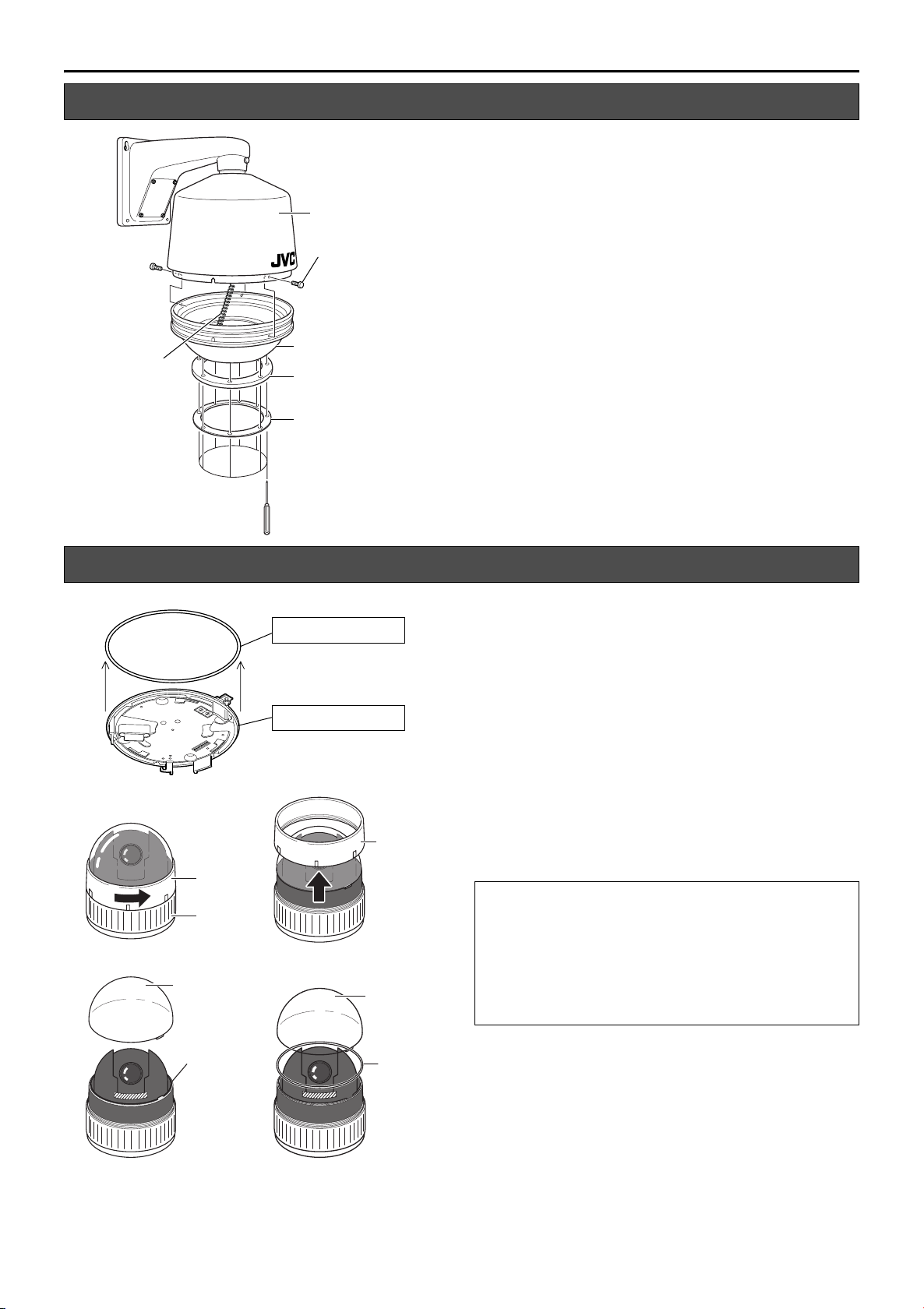
Disassembling the Housing
1. Dismantle the gasket and gasket gland
Main Housing Unit
Safety Wire
Screw A (M4 x 6) x 3
2.
Lower Housing
Gasket
2. Dismantle the lower housing
Loosen the 8 Screws B (M4) using a driver, followed by
dismantling the gasket and gasket gland from the lower
housing.
T The 8 Screws B (M4) cannot be totally removed from
the gasket to prevent it from falling off.
Loosen the 3 Screws A (M4 x 6) using a driver, followed
by dismantling the lower housing from the main housing
unit.
T The lower housing is connected to the main housing
unit using a safety wire.
1.
Gasket Gland
Screw B (M4) x 8
Procedures Before Mounting the Camera
1.
2.
A
C
Camera
Body Cover
Main Unit
Dome
Cover
Rubber Gasket (White)
Ceiling Mount
B
D
Camera
Body
Cover
Dome Cover
1. Dismantle the rubber gasket of the camera’s
ceiling mount
Dismantle the rubber gasket (white) on the same side as
the ceiling mount of the combination camera to be
installed.
2. Dismantle the rubber gasket in the interior of the
camera
Follow the procedures below to remove the rubber gasket
from the interior of the combination camera.
A Turn the camera body cover in the direction as indicated in
the left diagram.
(When the camera body cover is tight and cannot be
turned, do so upon fastening the main unit.)
B Dismantle the camera body cover.
C Dismantle the dome cover.
D Remove the rubber gasket and restore the dome cover and
camera body cover to their original positions.
CAUTION:
● The combination camera is an enclosed unit. In order to
prevent fogging in the interior of the dome cover, ensure to
remove the rubber gasket (2 types) before use.
● Do not remove the combination camera from the housing
and use it singly after removing the rubber gasket and
installing to the housing. Doing so may cause the camera
to malfunction.
10
Rubber
Gasket
Rubber
Gasket
Page 11

TK-C655 and TK-C676
Mounting the Camera (TK-C655E and TK-C676E)
Safety Wire
Main Board
AC 24 V Output
Cable
Interior of Housing
JVC Mark
2.
1.
3.
Notch
Camera Mounting Bracket
Cables
F Mark
Ceiling
Mount
Screws Supplied
(4 pcs)
1. Connect the AC 24 V output cable to the camera
Connect the AC 24 V output cable to the ceiling mount of
the camera to be installed.
2. Connect other cables
Connect the coaxial video cable and communication
cables (alarm signal, control terminal, etc.) supplied with
the housing to the ceiling mount.
CAUTION:
● Connect the communication cable to the [ALARM IN/OUT]
and [CONTROL] terminals if necessary. For safety
reasons, ensure to cut off any excess cable and bind using
an insulating tape before use.
● For further details on connection, please refer to the
instruction manual of the camera in use.
● Ensure to bind connectors of LAN cables and DC 12 V
Power Cable that are not in use with an insulating tape
before use.
3. Mount the ceiling mount of the camera to the
main housing unit
Use the 4 screws supplied to mount the ceiling mount to
the main housing unit.
CAUTION:
During mounting, align the F mark of the ceiling mount with
the notch on the camera mount bracket of the main housing
unit.
To [POWER INPUT AC 24 V]
Terminal of Ceiling Mount
4.
4. Mount the camera to the ceiling mount
Follow instructions in the manual of the camera to be
installed to mount the camera to the ceiling mount.
Camera
11
Page 12

Installation and Connection (WB-1550U)
Mounting the Camera (VN-C655U)
VN-C655
Screw (M4) x 4
1. 2.
Camera Mounting
Bracket
Main Housing Unit
3.
Connector
Connect to AC 24 V Output Cable
1.
Main Board
AC 24 V
Output Cable
5mm
Connector
Screw (M3) x 2
Converter Unit
Mounting Bracket
4.
To [POWER INPUT DC 18 V]
Terminal of Ceiling Mount
AC 24 V Output Cable
Press
5mm
Press
Press
Connector
2.
Interior of Housing
JVC Mark
To [P OWE R
INPUT DC
18 V]
Terminal of
Ceiling
Mount
Notch
Preparation
1. Dismantle the camera mounting bracket
Loosen the screws on the camera mounting bracket (M4,
4 pcs) using a driver to dismantle it.
2. Dismantle the converter unit mounting bracket
Loosen the screws on the converter unit mounting bracket
(M3, 2 pcs) using a driver to dismantle it.
3. Mount the converter unit to the housing
Clamp the converter unit using the converter unit
mounting bracket, followed by mounting it to the housing
using the screws (M3, 2 pcs) removed in Step 2.. When
mounting, pay attention to the orientation of the converter
unit as shown in the left diagram.
4. Mount the camera mounting bracket
Mount the camera mounting bracket dismantled in step 1.
to the housing. Mount it exactly to the original position.
Mounting
Before mounting.
Remove the ceiling mount cover of the camera and guide the
cables supplied with WB-1550U through the cover.
T For further details, please refer to the instruction manual of
the camera in use.
1.
Connect the AC 24 V output cable to the converter unit.
Follow the procedures below to connect the AC 24 V
output cable of the main board on the main housing unit to
the converter unit.
A Push both ends of the connector as shown in the left
diagram to remove it from the supplied converter unit.
B Cut the Y terminal of the AC 24 V output cable and peel
off about 5 mm of the coating.
C Push the arrow mark using tools such as a flat-head
screwdriver to insert the coating of the AC 24 V output
cable into the connector.
D Attach the connector to the converter unit.
2.
Mount the Y terminal of the converter unit to the
ceiling mount of VN-C655U.
Guide the Y terminal of the converter unit through the
ceiling mount cover, followed by connecting it to the
[POWER INPUT DC 18 V] terminal of VN-C655U’s ceiling
mount.
3. Connect other cables
Connect the necessary cables supplied with the housing
(coaxial video cable, alarm signal cable, LAN cable, etc.)
to the corresponding terminals on the ceiling mount.
12
Main Board
Safety Wire
Cables
3.
4.
Camera Mounting Bracket
F Mark
Ceiling Mount
Screws Supplied (4 pcs)
5.
Camera
CAUTION:
●
Connect the communication cable to the alarm terminal if
necessary.
on this system.
excess cable and bind using an insulating tape before use.
● For further details on connection, please refer to the
instruction manual of the camera in use.
In addition, DC 12 V Power Cable is not in use
For safety reasons, ensure to cut off any
4. Mount the camera’s ceiling mount to the main
housing unit.
Use the screws supplied (4 pcs) to mount the ceiling
mount to the main housing unit.
NOTE:
During mounting, align the F mark of the ceiling mount with the
notch on the camera mount bracket of the main housing unit.
5. Mount the camera to the ceiling mount
Follow instructions in the manual of the camera in use to
mount the camera to the ceiling mount.
Page 13

Assembling the Housing
Main Housing Unit
Screw A (M4 x 6) x 3
Safety Wire
1.
Desiccant
2.
Lower Housing
Position Mark
Gasket
3.
Gasket Gland
Screw B (M4) x 8
1. Mount the desiccant
Use a tape to adhere the supplied desiccant to the interior
of the lower housing.
CAUTION:
● Fogging may occur when there are drastic temperature
changes. In this case, continue using without turning off
the power.
● Pay attention when handling the desiccant in order to
maintain its effectiveness.
• Do not remove it from the bag until you are about to use
it.
• Do not wet it or touch it with wet hands.
• Assemble promptly upon adhering the desiccant.
• Be sure to replace the desiccant during maintenance.
2. Mount the lower housing
Mount the lower housing that is dismantled in Step 2.
(A pg. 10) to the main housing unit using the 3 Screw A
(M4 x 6).
Do so by aligning the position marks of the lower housing
and the main housing unit.
3. Mount the gasket and gasket gland
Mount the gasket and gasket gland that are dismantled in
Step 1. (A pg. 10) of the housing disassembly procedure
to the lower housing using the 8 Screws B (M4).
CAUTION:
● During assembly, ensure that wires and cables are not
caught in the housing.
● Do not exert force unnecessarily on the gasket or twist it
during mounting.
● Check to ensure that the gasket is in close contact with the
camera.
Mounting the Housing to the wall
Anchor Bolt
(M8, 35 mm and above)
Safety Wire
Installation Position
152
126
63
45
1. 2.
12
30
60
Washer
202
176
Nut
1. Drill a hole into the wall.
2. Affix anchor bolts onto the wall.
• Affix 4 anchor bolts (M8, 35 mm and above) for attaching
• Affix an anchor bolt for attaching the safety wire, in the
3. Mount the safety wire and arm to the wall.
• Mount the safety wire attached to the housing, to the
• Use the nut and wire to mount the housing onto the wall.
Drill a hole (R 45 mm) for inserting the connection cable.
(Refer to left fig.)
the housing. (Refer to left fig.)
middle (about 60 mm from both ends) of the 2 upper
anchor bolts, 30 mm from the top. (Refer to left fig.)
anchor bolts using the nut and wire.
13
Page 14
Installation and Connection (WB-1550U)
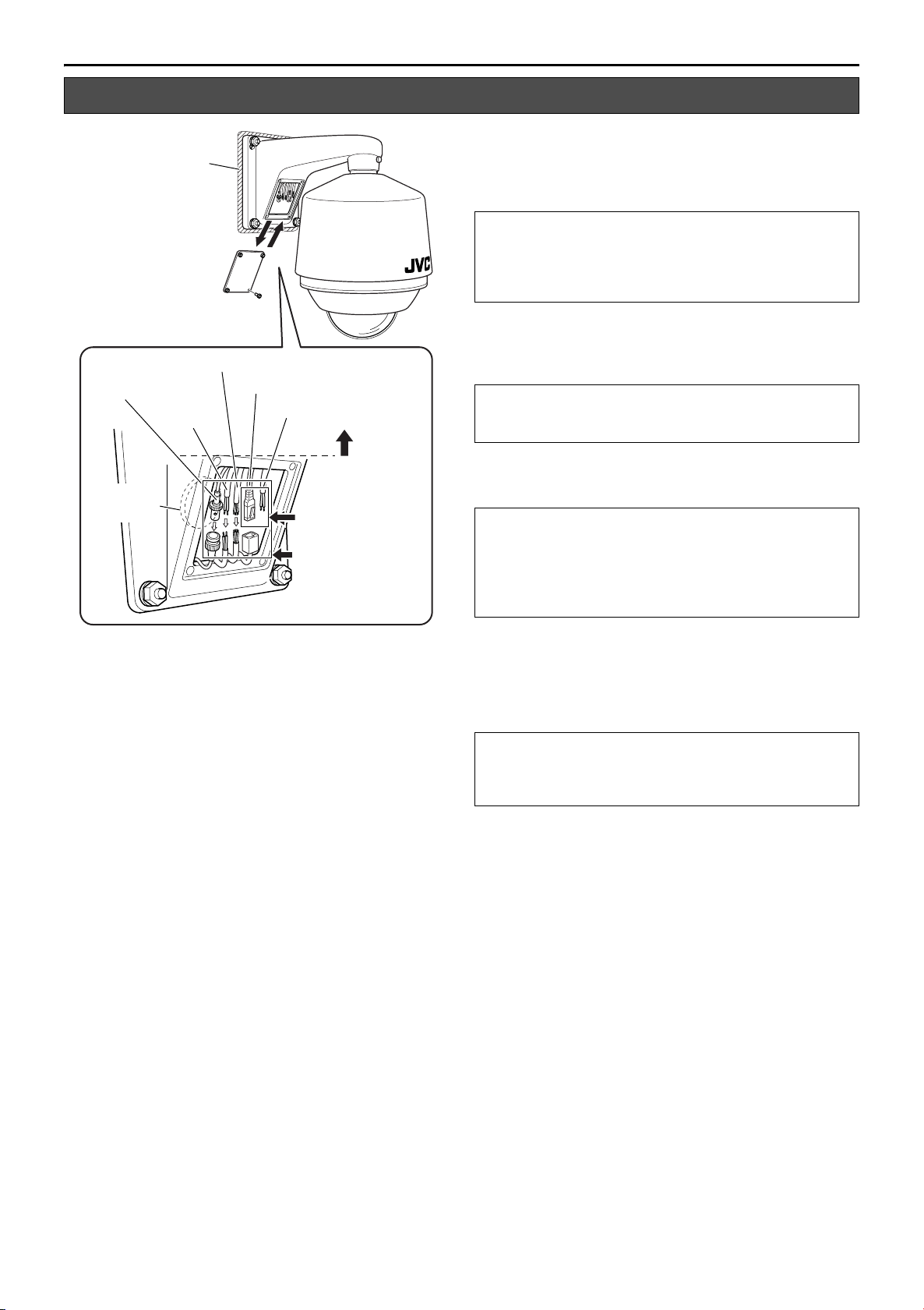
Mounting the Housing to the Wall (continued)
4. Open the cable connection cover
Use provided hexagon wrench to remove the 4 screws
Wate rp roofi ng
Screw (M3 x 12) x 4
Alarm/Communication Cable
Coaxial Video Cable
AC 24 V
Powe r Cabl e
8.
Hole
Wate rp roofi ng
T Not in use on this system.
8.
4.
LAN Cable (Male)
9.
T DC 12 V Power Cable
7.
5.
Bind with insulating tape
Bind using a waterproof
(adhesive) tape
6.
(M3 x 12) from the cable connection cover to open it.
5. Connect each cable
Connect the necessary cables.
CAUTION:
● Ensure to bind connectors of LAN cables that are not in
use with an insulating tape before use.
● Ensure to bind the DC 12 V Power Cable that is not in use
on this system with insulating tape.
6. Bind cable using a waterproof tape
Upon connecting, ensure to perform waterproofing
procedures by binding the joint of each cable with a
waterproof (adhesive) tape.
CAUTION:
For safety reasons, turn on the power only upon connecting
all cables.
7. Fasten the cables in the interior of the arm
When waterproofing is complete, insert the cables into the
upper interior of the arm and fasten using a tape.
CAUTION:
When inserting the cables, ensure that all cable connections
are above the cable connection cover (see dotted line in the
left diagram).
Failure to do so may cause malfunctions due to penetration
of rain water.
8. Cover the hole and the mounting side of
housing with waterproof seal.
After the cables have been connected, cover the holes made
1.
in step
cover open, put your hand in and cover the hole. Cover the
mounting side of the housing with waterproof seal.
with waterproof seal. With the Cable connection
NOTE:
● Be sure to perform waterproofing. Seepage of rainwater
may result in malfunction.
● Use GE silicon or its equivalents as the sealing material.
9. Close the cable connection cover
When cable connection is complete, close the cable
connection cover and fasten the 4 screws (M3 x 12)
removed in step 4. using the provided hexagon wrench.
14
Page 15

Others
294
260
152
126
Ǟ
260
257
413
12
176
202
356
2
-R4.5
2-
R
7
.75
2-Ǟ9 hole
294
260
152
126
244
415
12
176
202
343
2-R4.5
Ǟ
260
2-
R
7
.75
2-Ǟ9 hole
Specifications
WB-1540U
䡵 General
Power / Voltage : AC 24 V 50 Hz/60 Hz (Main Housing Unit)
Power Consumption
: 25 W (During heater operation, excluding
camera)
Installation Location
: Outdoor (general)
Ambient Temperature
: -20 I to 50 I (when equipped with
TK-C625U/E)
: -20 I to 40 I (when equipped with
VN-C625U)
Heater Operation Temperature (Internal temperature)
: Heater turns ON between 8 I ± 5 I
Turns OFF between 20 I ± 5 I
Ambient Humidity : 35 % to 90 %
Vibration / Shock : Locations without vibration/shock
Dustproof / Waterproof
: IP66
T When combined with compatible
camera
Permissible Wind Speed
: 40 m/s or below
䡵 Mass: 5.0 kg
䡵 Accessories:
Instructions ...............................1
Desiccant..................................1
Screw (M4×20).........................4
Hexagon wrench.......................1
䡵 Compatible Cameras: TK-C625U/E, VN-C625U
䡵 Dimensional Outline Drawing (Unit: mm)
T Specifications and appearance of this unit as well as related
products may be modified for improvement without prior
notice.
WB-1550U
䡵 General
Power / Voltage : AC 24 V 50 Hz/60 Hz (Main Housing Unit)
Power Consumption
: 25 W (During heater operating, excluding
camera)
Installation Location
: Outdoor (general)
Ambient Temperature
: -20 I to 50
TK-C676E, TK-C655E)
: -20 I to 40 I (when equipped with
VN-C655U)
Heater Operation Temperature (Internal temperature)
: Heater turns ON between 8 I ± 5 I
Turns OFF between 20 I ± 5 I
Ambient Humidity : 35 % to 90 %
Vibration / Shock : Locations without vibration/shock
Dustproof / Waterproof
:IP66
T When combined with compatible
camera
Permissible Wind Speed
: 40 m/s or below
I (when equipped with
䡵 Mass: 5.0 kg
䡵 Accessories:
Instructions ...............................1
Desiccant..................................1
Screw (M4×20).........................4
Hexagon wrench.......................1
䡵 Compatible Cameras: TK-C676E, TK-C655E, VN-C655U
䡵 Dimensional Outline Drawing (Unit: mm)
T Specifications and appearance of this unit as well as related
products may be modified for improvement without prior
notice.
15
Page 16

WB-1540U/WB-1550U OUTDOOR HOUSING
© 2007 Victor Company of Japan, Limited
LST0267-001C
 Loading...