

Page 1
OUTDOOR HOUSING
WB-1540
WB-1550
DEUTSCHFRANÇAISESPAÑOLITALIANO ENGLISH
INSTRUCTIONS
For Customer Use:
Enter below the Serial No. which is located on
the body.
Retain this information for future reference.
Model No. WB-1540/WB-1550
Serial No.
This instruction book is made from 100% recycle paper.
LST0267-001A
Page 2
These are general IMPORTANT SAFEGUARDS and certain items may not apply to all appliances.
IMPORTANT SAFEGUARDS
1. Read all of these instructions.
2. Save these instructions for later use.
3. All warnings on the product and in the operating instructions should be adhered to.
4. Unplug this appliance system from the wall outlet before cleaning.Do not use liquid cleaners or aerosol cleaners.Use a damp cloth for cleaning.
5. Do not use attachments not recommended by the appliance manufacturer as they may cause hazards.
6. Do not use this appliance near water - for example, near a bathtub, washbowl, kitchen sink, or laundry tub, in a wet basement, or near a
swimming pool, etc.
7. Do not place this appliance on an unstable cart, stand, or table. The appliance may fall, causing serious injury to a
child or adult, and serious damage to the appliance may fall, causing serious injury to a child or adult, and serious
damage to the appliance.
Use only with a cart or stand recommended by the manufacturer, or sold with the appliance. Wall or shelf mounting
should follow the manufacturer’s instructions, and should use a mounting kit approved by the manufacturer.
An appliance and cart combination should be moved with care. Quick stops, excessive force, and uneven surfaces
may cause the appliance and cart combination to overturn.
8. Slots and openings in the cabinet and the back or bottom are provided for ventilation, and to insure reliable operation
of the appliance and to protect it from overheating,these openings must not be blocked or covered. The openings
should never be blocked by placing the appliance on a bed, sofa, rug, or other similar surface. This appliance should
never be placed near or over a radiator or heat register. This appliance should not be placed in a built-in installation such as a bookcase unless
proper ventilation is provided.
9. This appliance should be operated only from the type of power source indicated on the marking label. If you are not sure of the type of power
supplied to your home, consult your dealer or local power company. For appliance designed to operate from battery power, refer to the operating
instructions.
10.For added protection for this product during a lightning storm, or when it is left unattended and unused for long periods of time, unplug it from
the wall outlet and disconnect the antenna or cable system. This will prevent damage to the product due to lightning and power-line surges.
11.Do not allow anything to rest on the power cord. Do not locate this appliance where the cord will be abused by persons walking on it.
12.Follow all warnings and instructions marked on the appliance.
13.Do not overload wall outlets and extension cords as this can result in fire or electric shock.
14.Never push objects of any kind into his appliance through cabinet slots as they mat touch dangerous voltage points or short out parts that
could result in a fire or electric shock. Never spill liquid of any kind on the appliance.
15.Do not attempt to service this appliance yourself as opening or removing covers may expose you to dangerous voltage or other hazards.
Refer all servicing to qualified service personnel.
16.Unplug his appliance from the wall outlet and refer servicing to qualified service personnel under following conditions:
a. When the power cord or plug is damaged or frayed.
b. If liquid has been spilled into the appliance.
c. If the appliance has been exposed to rain or water.
d. If the appliance does not operate normally by following the operating instructions. Adjust only those controls that are covered by the
operating instructions as improper adjustment of other controls may result in damage and will often require extensive work by a qualified
technician to restore the appliance to normal operation.
e. If the appliance has been dropped or the cabinet has been damaged.
f. When the appliance exhibits a distinct change in performance - this indicates a need for service.
17.When replacement parts are required, be sure the service technician has used replacement parts specified by the manufacturer that have
the same characteristics as the original part. Unauthorized substitutions may result in fire, electric shock, or other hazards.
18.Upon completion of any service or repairs to this appliance, ask the service technician to perform routine safety checks to determine that the
appliance is in safe operating condition.
WARNING
For USA and CANADA
TO PREVENT FIRE OR SHOCK HAZARD, DO NOT
EXPOSE THIS UNIT TO RAIN OR MOISTURE.
Information for USA
This device complies with Part 15 of the FCC Rules.
Changes or modifications not approved by JVC could void the
user’s authority to operate the equipment.
S3125A
INFORMATION (FOR CANADA) RENSEIGNEMENT
(POUR LE CANADA)
The lightning flash with arrowhead symbol, within an
equilateral triangle, is intended to alert the user to
the presence of uninsulated “dangerous voltage”
within the product’s enclosure that may be of
sufficient magnitude to constitute a risk of electric
shock to persons.
The exclamation point within an equilateral triangle
is intended to alert the user to the presence of
important operating and maintenance (servicing)
instructions in the literature accompanying the
appliance.
This Class [B] digital apparatus complies with Canadian ICES-003.
Cet appareil numérique de la classe [B] est conforme à la norme
NMB-003 du Canada.
Due to design modification, data given in this instruction
book are subject to possible change without prior notice.
2
Page 3
Information for Users on Disposal of Old Equipment
[European Union]
This symbol indicates that the electrical and electronic equipment should not be disposed as general household waste at its end-of-life. Instead, the product should be
handed over to the applicable collection point for the recycling of electrical and electronic equipment for proper treatment, recovery and recycling in accordance with your
national legislation.
By disposing of this product correctly, you will help to conserve natural resources and will help prevent potential negative effects on the environment and human health
which could otherwise be caused by inappropriate waste handling of this product. For more information about collection point and recycling of this product, please
contact your local municipal office, your household waste disposal service or the shop where you purchased the product.
Penalties may be applicable for incorrect disposal of this waste, in accordance with national legislation.
Attention:
This symbol is only
valid in the European
Union.
(Business users)
If you wish to dispose of this product, please visit our web page www.jvc-europe.com to obtain information about the take-back of the product.
[Other Countries outside the European Union]
If you wish to dispose of this product, please do so in accordance with applicable national legislation or other rules in your country for the treatment of old electrical and
electronic equipment.
Benutzerinformationen zur Entsorgung alter Geräte
[Europäische Union]
Dieses Symbol zeigt an, dass das elektrische bzw. elektronische Gerät nicht als normaler Haushaltsabfall entsorgt werden soll. Stattdessen sollte das Produkt zur
fachgerechten Entsorgung, Weiterverwendung und Wiederverwertung in Übereinstimmung mit der Landesgesetzgebung einer entsprechenden Sammelstelle für das
Recycling elektrischer und elektronischer Geräte zugeführt werden.
Die korrekte Entsorgung dieses Produkts dient dem Umweltschutz und verhindert mögliche Schäden für die Umwelt und die menschliche Gesundheit, welche durch
unsachgemäße Behandlung des Produkts auftreten können. Weitere Informationen zu Sammelstellen und dem Recycling dieses Produkts erhalten Sie bei Ihrer
Gemeindeverwaltung, Ihrem örtlichen Entsorgungsunternehmen oder in dem Geschäft, in dem Sie das Produkt gekauft haben.
Hinweis:
Dieses Symbol ist nur
in der Europäischen
Union gültig.
Für die nicht fachgerechte Entsorgung dieses Abfalls können gemäß der Landesgesetzgebung Strafen ausgesprochen werden.
(Geschäftskunden)
Wenn Sie dieses Produkt entsorgen möchten, besuchen Sie bitte unsere Webseite www.jvc-europe.com, um Informationen zur Rücknahme des Produkts zu erhalten.
[Andere Länder außerhalb der Europäischen Union]
Wenn Sie dieses Produkt entsorgen möchten, halten Sie sich dabei bitte an die entsprechenden Landesgesetze und andere Regelungen in Ihrem Land zur Behandlung
elektrischer und elektronischer Geräte.
ENGLISH
DEUTSCH
Informations relatives à l’élimination des appareils usagés, à l’intention des utilisateurs
[Union européenne]
Lorsque ce symbole figure sur un appareil électrique et électronique, cela signifie qu’il ne doit pas être éliminé en tant que déchet ménager à la fin de son cycle de vie.
Le produit doit être porté au point de pré-collecte approprié au recyclage des appareils électriques et électroniques pour y subir un traitement, une récupération et un
recyclage, conformément à la législation nationale.
En éliminant correctement ce produit, vous contriburez à la conservation des ressources naturelles et à la prévention des éventuels effets négatifs sur l’environnement et
la santé humaine, pouvant être dus à la manipulation inappropriée des déchets de ce produit. Pour plus d’informations sur le point de pré-collecte et le recyclage de ce
produit, contactez votre mairie, le service d’évacuation des ordures ménagères ou le magasin dans lequel vous avez acheté le produit.
Des amendes peuvent être infligées en cas d’élimination incorrecte de ce produit, conformément à la législation nationale.
Attention:
Ce symbole n’est
reconnu que dans
l’Union européenne.
(Utilisateurs professionnels)
Si vous souhaitez éliminer ce produit, visitez notre page Web www.jvc-europe.com afin d’obtenir des informations sur sa récupération.
[Pays ne faisant pas partie de l’Union européenne]
Si vous souhaitez éliminer ce produit, faites-le conformément à la législation nationale ou autres règles en vigueur dans votre pays pour le traitement des appareils
électriques et électroniques usagés.
Información para los usuarios sobre la eliminación de equipos usados
[Unión Europea]
Este símbolo indica que los aparatos eléctricos y electrónicos no deben desecharse junto con la basura doméstica al final de su vida útil. El producto deberá llevarse al
punto de recogida correspondiente para el reciclaje y el tratamiento adecuado de equipos eléctricos y electrónicos de conformidad con la legislación nacional.
Si desecha el producto correctamente, estará contribuyendo a conservar los recursos naturales y a prevenir los posibles efectos negativos en el medio ambiente y en la
salud de las personas que podría causar el tratamiento inadecuado del producto desechado. Para obtener más información sobre el punto de recogida y el reciclaje de
este producto, póngase en contacto con su oficina municipal, su servicio de recogida de basura doméstica o la tienda en la que haya adquirido el producto.
De acuerdo con la legislación nacional, podrían aplicarse multas por la eliminación incorrecta de estos desechos.
Atención:
Este simbolo solo
es valido en la
Union Europea.
(Empresas)
Si desea desechar este producto, visite nuestra página Web www.jvc-europe.com para obtener información acerca de la retirada del producto.
[Otros países no pertenecientes a la Unión Europea]
Si desea desechar este producto, hágalo de conformidad con la legislación nacional vigente u otras normativas de su país para el tratamiento de equipos eléctricos y
electrónicos usados.
Informazioni per gli utenti sullo smaltimento delle apparecchiature obsolete
[Union Europea]
Questo simbolo indica che l’apparecchiatura elettrica ed elettronica a cui è relativo non deve essere smaltita tra i rifiuti domestici generici alla fine della sua vita utile. Il
prodotto, invece, va consegnato a un punto di raccolta appropriato per il riciclaggio di apparecchiature elettriche ed elettroniche, per il trattamento, il recupero e il
riciclaggio corretti, in conformità alle proprie normative nazionali.
Mediante lo smaltimento corretto di questo prodotto, si contribuirà a preservare le risorse naturali e a prevenire potenziali effetti negativi sull’ambiente e sulla salute
umana che potrebbero essere provocati, altrimenti, da uno smaltimento inappropriato del prodotto. Per ulteriori informazioni sul punto di raccolta e il riciclaggio di questo
prodotto, contattare la sede comunale locale, il servizio di smaltimento rifiuti domestici o il negozio in cui si è acquistato il prodotto.
L’ utente è responsabile del conferimento dell’apparecchio a fina vita alle appropriate strutture di raccolta, pena le sanzioni previste dalla vigente legislazione sui rifiuti.
Attenzione:
Questo simbolo è
valido solo nell’Unione
Europea.
(Per gli utenti aziendali)
Qualora si desideri smaltire questo prodotto, visitare la nostra pagina web www.jvc-europe.com per ottenere informazioni sul ritiro del prodotto.
[Per altre nazioni al di fuori dell’Unione Europea]
Qualora si desideri smaltire questo prodotto, effettuare lo smaltimento in conformità alla normativa nazionale applicabile o alle altre leggi della propria nazione relative al
trattamento delle apparecchiature elettriche ed elettroniche obsolete.
FRANÇAIS
CASTELLANO
ITALIANO
3
Page 4

Getting Started
Thank you for purchasing this product. (These instructions are for WB-1540U/ WB-1550U)
Before beginning to operate this unit, please read the instruction manual careully in order to make sure that the best possible
performance is obtained.
The compatible cameras for each housing are as follows:
● WB-1540: TK-C625U/E,VN-C625U
● WB-1550: TK-C676E,TK-C655E,VN-C655U
Table of Contents
Getting Started
Table of Contents ...................................................................4
Operating Precautions ...........................................................4
System Example ....................................................................5
VN-C625 and VN-C655 Systems ......................................5
TK-C625, TK-C655 and TK-C676 Systems .......................5
Installation and Connection (WB-1540)
Disassembling the Housing ....................................................6
Mounting the Camera ............................................................6
TK-C625 ............................................................................6
VN-C625 ............................................................................7
Assembling the Housing ........................................................8
Mounting the Housing to the wall ...........................................8
Installation and Connection (WB-1550)
Disassembling the Housing .................................................10
Procedures Before Mounting the Camera ........................... 10
Mounting the Camera .........................................................11
TK-C655 and TK-C676 ...................................................11
VN-C655 .........................................................................12
Assembling the Housing ......................................................13
Mounting the Housing to the wall ........................................13
Others
Specifications ......................................................................15
WB-1540 ......................................................................... 15
WB-1550 ......................................................................... 15
Operating Precautions
䡵 Depending on the installation environment of this unit, the
life span of the attached camera may decrease significantly.
Give close attention to the installation location (especially if
used continuously under high temperature or in locations
constantly exposed to direct sunlight).
䡵 As the interior of this unit will heat up, be sure to use San
Disk (industrial) if loading the CF card to VN-C625.
䡵 This unit may stop functioning properly due to natural
hazards as it is to be installed outdoors. To take
photographs properly, be sure to perform daily checks.
䡵 Do not install this unit in locations with sharp temperature
changes, such as near air-con compressors or exhaustpipes. Condensation may occur inside the attached
combination camera.
䡵 To save energy, switch off the system when not in use.
䡵 For safety reasons special techniques are necessary for
installation. Consult your dealer regarding installation, and
ensure that it is carried out by a specialist.
䡵 Be sure to mount the safety wire for safety purposes. If it
falls, it may cause injury or accidents.
䡵 Ta king vibrations, mass and wind force into account, ensure
to mount in a location with sufficient strength using solid
anchor bolts. If reinforced or spiral nuts are not tightened
enough, picture blurring may occur on the monitor screen
due to vibration, and in the worst case there is a danger of
falling.
䡵 Use at the voltage indicated. A voltage other than that
displayed may result in fire or electric shocks.
䡵 This unit supports lightning conduction to the connection
cable to some extent, but not fully. At installation locations
where there may be a lightning hazard, be sure to add an
arrester to the connection cable or take other precautions.
䡵 Do not dangle, shake, or hook objects. If too much load is
placed on top, it may fall and cause injury or accidents.
䡵 If a ball or bird hits this unit, bringing about some sort of
trouble, consult your dealer or the nearest Victor service
center.
䡵 Do not modify this unit yourself. Accidents may result.
䡵 Do not install in locations where there may be vibrations or
impact. If it falls, it may cause injury or accidents.
䡵 Regularly check for the deterioration of attaching parts and
the loosening of the screws caused by vibrations. If it falls, it
may cause injury or accidents.
䡵 Do not install in locations where radiation, X-rays, or
corrosive gases are emitted. Doing so may cause the
camera to malfunction.
䡵 Keep all packaging out of the reach of children. If used for
play, it may cause injury or suffocation.
4
Page 5
System Example
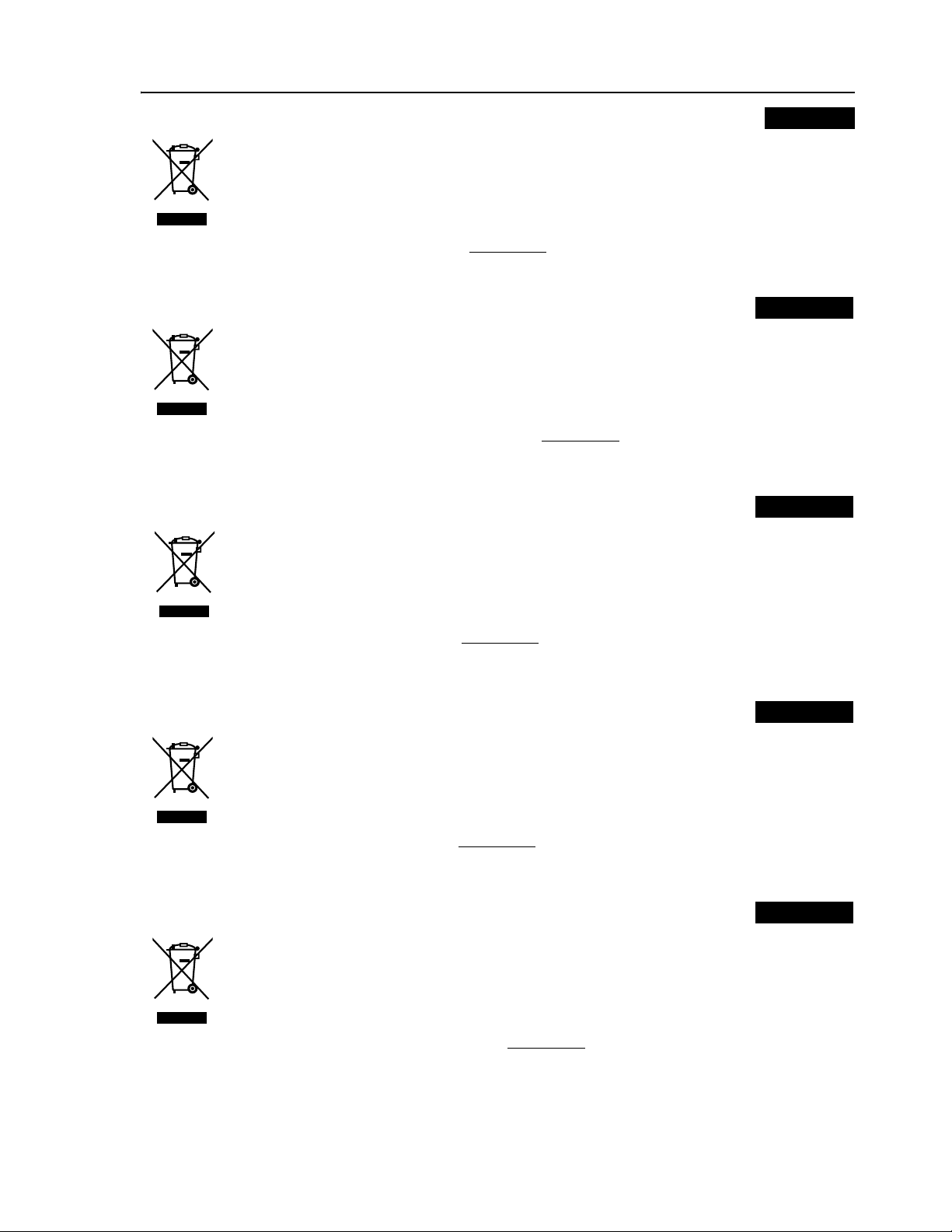
VN-C625 and VN-C655 Systems
WB-1540 / WB-1550
Powe r Cable (DC 12V)
Not in use on this system. (T1)
Power Cable
(AC 24V)
AC 24 V Power Supply
T1
Coaxial Cable
Monitor
WB-1540 / WB-1550 (Main Board)
LED1
Alarm Cable
Alarm Device
To TB 1
(Connected)
VN-C625/655
Supplied Converter
Unit
To [P OWER INPUT DC 18 V]
Te rminal (VN-C655)
To [P OWER INPUT DC 12 V]
Te rminal (VN-C625)
TB1 AC24V ~ INPUT
TO CAMERA
Fuse T
To [V IDEO OUT] Terminal
To [ALARM IN/OUT] Terminal
To [10 BASE-T/100 BASE-TX] Terminal
Ceiling Mount of Network Camera
LAN Cable
Power Indicator
Red light turns on during power supply.
LAN
PC
CAUTION:
T1: Not in use on this system. Ensure to bind both ends of cables that are not in use with insulating tape.
T2: Power will not be supplied to this unit and the installed camera when the fuse on the main board burns out. When this
occurs, please consult your nearby JVC dealer as exchange of fuse according to the rating (125 V - 5 A) will be required.
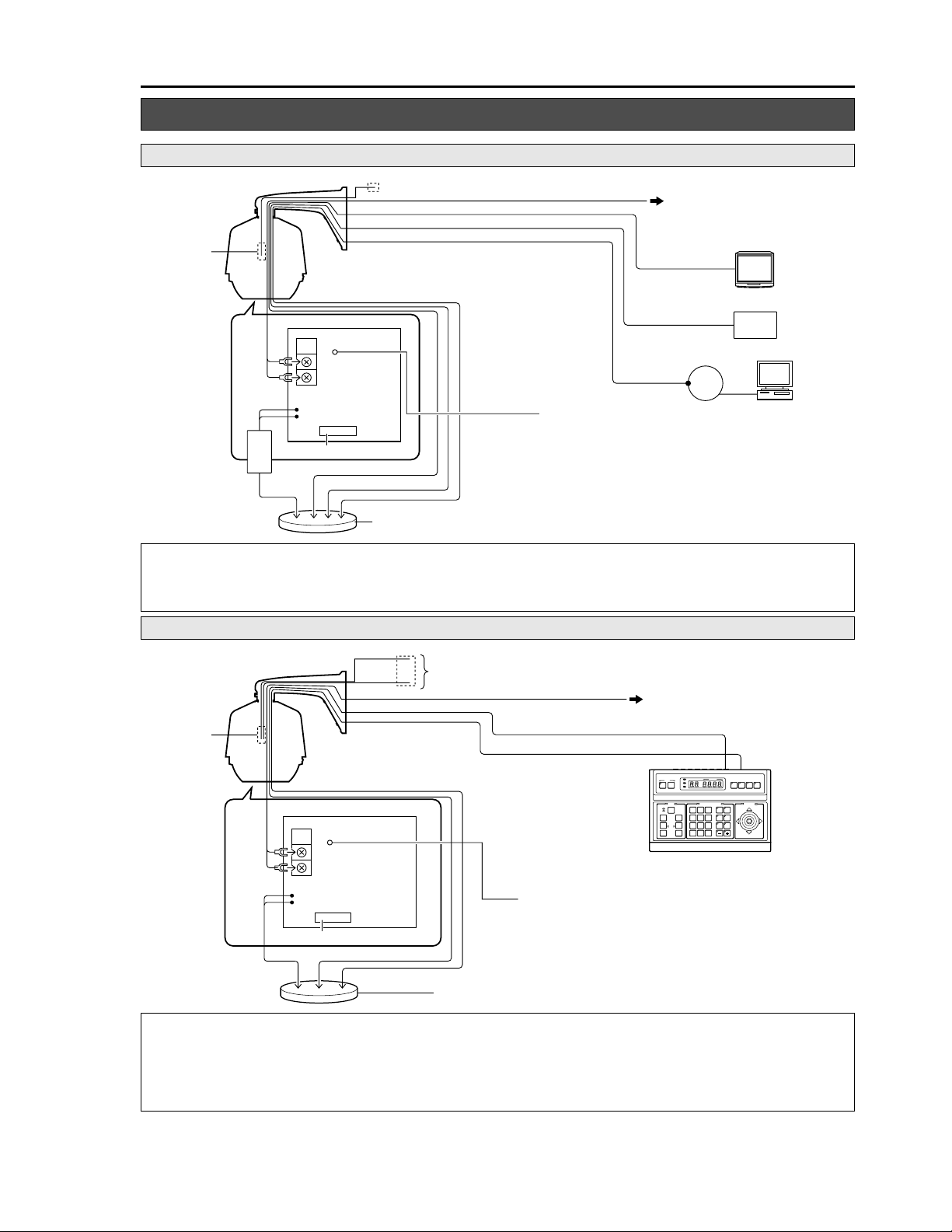
TK-C625, TK-C655 and TK-C676 Systems
WB-1540 / WB-1550
Power Cable (DC 12 V)
LAN Cable
Not in use on this system. (T1)
Power Cable (AC 24 V)
To In sulated AC 24 V Power Supply
T1
WB-1540 / WB-1550 (Main Board)
To T B 1
(Connected)
TO CAMERA
LED1
TB1 AC24V ~ INPUT
Coaxial Cable
Communication Cable
Powe r Indicator
Red light turns on during power supply.
SETUP
MENU SET
SPEED
IRIS
CLOSE
FOCUS
NEAR
WIDE
ZOOM
POWER
ALARM
KEYLOCK
OPEN
FAR
AF
TELE CLEAR
RM-P2580
CAMERA POSITION
CAMERA/POSITION
1
2
4
5
7
8
0
/HOME
VIDEO INPUT
REMOTECONTROLUNIT
AUTO F-1 F-2 F-3
CAMERA
POSI-
3
TION
OPTION1OPTION
6
2
AUTO
AUTO
9
PAN
PATROL
ENTER
TO CAMERA
RM-P2580
PAN/TILTLENS
Fuse T
To [VIDEO OUT/TO CCU] Terminal
To [P OWE R INPUT
AC 24 V ~] Terminal
To [CONTROL/ALARM IN, OUT] Terminal
Ceiling Mount of Combination Camera
CAUTION:
● Ensure to turn of the power of devices in use before connecting.
Refer to the instruction manual for the combination camera that is supplied with this unit as well during connection and installation.
●
T1: Not in use on this system. Ensure to bind both ends of cables that are not in use with insulating tape.
T2: Power will not be supplied to this unit and the installed camera when the fuse on the main board burns out. When this
occurs, please consult your nearby JVC dealer as exchange of fuse according to the rating (125 V - 5 A) will be required.
5
Page 6

Installation and Connection (WB-1540)
Disassembling the Housing
1. Dismantle the gasket and gasket gland
Main Housing Unit
2. Dismantle the lower housing
2.
Screw A (M4 x 6) x 3
Safety Wire
1.
Lower Housing
Gasket
Gasket Gland
Screw B (M4) x 6
Loosen the 6 Screws B (M4) using a driver, followed by
dismantling the gasket and gasket gland from the lower
housing.
T The 6 Screws B (M4) cannot be totally removed from
the gasket to prevent it from falling off.
Loosen the 3 Screws A (M4 x 6) using a driver, followed
by dismantling the lower housing from the main housing
unit.
T The lower housing is connected to the main housing
unit using a safety wire.
CAUTION:
Pay careful attention to store the dismantled parts and
screws until assembly is complete to prevent them from
being misplaced.
TK-C625
Mounting the Camera (TK-C625)
Interior of Housing
Safety Wire
Main Board
JVC Mark
Camera Mounting Bracket
Notch
Cables
2.
Cover
1.
AC 24 V
Output Cable
To [ P OW ER INPUT AC 24 V]
Te r mi n al of Ceiling Mount
3.
FRONT
Mark
Ceiling Mount
Screws Supplied
(M4 x 20) x 4
4.
Camera
Before mounting.
Remove the ceiling mount cover of the camera and guide the
cables supplied with WB-1540 through the cover.
T For further details, please refer to the instruction manual of
the camera in use.
1. Connect the AC 24 V output cable to the camera
Connect the AC 24 V output cable of the main board to
the camera’s ceiling mount bracket.
2. Connect other cables
Connect the necessary cables supplied with the housing
(coaxial video cable, communication cable, etc.) to the
ceiling mount.
CAUTION:
● Connect the communication cable to the [ALARM IN/OUT]
and [CONTROL] terminals if necessary. For safety
reasons, ensure to cut off any excess cable and bind using
an insulating tape before use.
● For further details on connection, please refer to the
instruction manual of the camera in use.
● Ensure to bind connectors of LAN cables and DC 12 V
Power Cable that are not in use with an insulating tape
before use.
3. Mount the camera’s ceiling mount to the main
housing unit.
Use the 4 screws supplied (M4 x 20) to mount the ceiling
mount to the main housing unit.
NOTE:
During mounting, align the [D FRONT] Mark of the ceiling
mount with the notch on the camera mount bracket of the
main housing unit.
4. Mount the camera to the ceiling mount
Follow instructions in the manual of the camera in use to
mount the camera to the ceiling mount.
6
Page 7

Mounting the Camera (VN-C625)
VN-C625
Screw (M4) x 4
1.
Camera
Mounting
Bracket
Connector
Main Housing Unit
3.
Connector
Connect to AC 24 V Output Cable
1.
Main Board
AC 24 V
Output Cable
5mm
Connector
Main Board
Safety Wire
Cables
3.
4.
Camera
Screw (M3) x 2
2.
4.
To [P OWE R I NPUT DC 12 V]
Te rminal of Ceiling Mount
AC 24 V Output Cable
Press
5mm
Press
Press
Connector
2.
Interior of Housing
JVC Mark
Camera Mounting Bracket
Cover
FRONT Mark
Ceiling Mount
Screws Supplied (M4 x 20) x 4
5.
Converter Unit
Mounting Bracket
To [P OWE R
INPUT DC
12 V]
Te rminal of
Ceiling
Mount
Notch
Preparation
1. Dismantle the camera mounting bracket
Loosen the screws on the camera mounting bracket (M4,
4 pcs) using a driver to dismantle it.
2. Dismantle the converter unit mounting bracket
Loosen the screws on the converter unit mounting bracket
(M3, 2 pcs) using a driver to dismantle it.
3. Mount the converter unit to the housing
Clamp the converter unit using the converter unit
mounting bracket, followed by mounting it to the housing
using the screws (M3, 2 pcs) removed in Step 2.
When mounting, pay attention to the orientation of the
converter unit as shown in the left diagram.
4. Mount the camera mounting bracket
Mount the camera mounting bracket dismantled in step 1.
to the housing. Mount it exactly to the original position.
Mounting
Before mounting.
Remove the ceiling mount cover of the camera and guide the
cables supplied with WB-1540 through the cover.
T For further details, please refer to the instruction manual of
the camera in use.
1.
Connect the AC 24 V output cable to the converter unit.
Follow the procedures below to connect the AC 24 V
output cable of the main board on the main housing unit to
the converter unit.
A Push both ends of the connector as shown in the left
diagram to remove it from the supplied converter unit.
B Cut the Y terminal of the AC 24 V output cable and peel
off about 5 mm of the coating.
C Push the arrow mark using tools such as a flat-head
screwdriver to insert the coating of the AC 24 V output
cable into the connector.
D Attach the connector to the converter unit.
2.
Mount the Y terminal of the converter unit to the
ceiling mount of VN-C625.
Guide the Y terminal of the converter unit through
the ceiling mount cover, followed by connecting it to
the [POWER INPUT DC 12 V] terminal of
VN-C625’s ceiling mount.
3. Connect other cables
Connect the necessary cables supplied with the housing
(coaxial video cable, alarm signal cable, LAN cable, etc.)
to the corresponding terminals on the ceiling mount.
CAUTION:
●
Connect the communication cable to the alarm terminal if
necessary. In addition, DC 12 V Power Cable is not in use
on this system. For safety reasons, ensure to cut off any
excess cable and bind using an insulating tape before use.
● For further details on connection, please refer to the
instruction manual of the camera in use.
4. Mount the camera’s ceiling mount to the main
housing unit.
Use the 4 screws supplied (M4 x 20) to mount the ceiling
mount to the main housing unit.
NOTE:
During mounting, align the [D FRONT] mark of the ceiling
mount with the notch on the camera mount bracket of the
main housing unit.
5. Mount the camera to the ceiling mount
Follow instructions in the manual of the camera in use to
mount the camera to the ceiling mount.
7
Page 8

Installation and Connection (WB-1540)
Assembling the Housing
Main Housing Unit
Screw A (M4 x 6) x 3
Safety Wire
1.
Desiccant
2.
Lower Housing
Position Mark
Gasket
3.
Gasket Gland
1. Adhering the desiccant
Use a tape to adhere the supplied desiccant to the interior
of the lower housing.
CAUTION:
● Fogging may occur when there are drastic temperature
changes. In this case, continue using without turning off
the power.
● Pay attention when handling the desiccant in order to
maintain its effectiveness.
•Do not remove it from the bag until you are about to use
it.
•Do not wet it or touch it with wet hands.
•Assemble promptly upon adhering the desiccant.
•Be sure to replace the desiccant during maintenance.
2. Mount the lower housing
Mount the lower housing that is dismantled in Step 2.
(A pg. 10) to the main housing unit using the 3 Screws A
(M4 x 6).
Do so by aligning the position marks of the lower housing
and the main housing unit.
3. Mount the gasket and gasket gland
Mount the gasket and gasket gland that are dismantled in
Step 1. (A pg.10) of the housing disassembly procedure
to the lower housing using the 6 Screws B (M4).
Screw B (M4) x 6
CAUTION:
● During assembly, ensure that wires and cables are not
caught in the housing.
● Do not exert force unnecessarily on the gasket or twist it
during mounting.
● Check to ensure that the gasket is in close contact with the
camera.
Mounting the Housing to the wall
Anchor Bolt
(M8, 35 mm and above)
Safety Wire
Installation Position
152
126
63
1. 2.
12
30
Washer
202
176
Nut
1. Drill a hole into the wall.
2. Affix anchor bolts onto the wall.
•Affix 4 anchor bolts (M8, 35 mm and above) for attaching
•Affix an anchor bolts for attaching the safety wire, in the
3. Mount the safety wire and arm to the wall.
•Mount the safety wire attached to the housing, to the
•Use the nut and wire to mount the housing onto the wall.
Drill a hole (R 45 mm) for inserting the connection cable.
(Refer to left fig.)
the housing. (Refer to left fig.)
middle (about 60 mm from both ends) of the 2 upper
anchor bolts, 30 mm from the top. (Refer to left fig.)
anchor bolts using the nut and wire.
45
60
8
Page 9

Mounting the Housing to the Wall (continued)
4. Open the cable connection cover
Use provided hexagon wrench to remove the 4 screws
(M3 x 12) from the cable connection cover to open it.
Water proofing
Screw (M3 x 12) x 4
Alarm/Communication Cable
Coaxial
Video Cable
8.
Hole
Waterproofin g
T Not in use on this system.
AC 24 V
Power Cable
8.
4.
LAN Cable (Male)
9.
T DC 12 V Power Cable
7.
5.
Bind with insulating tape
Bind using a waterproof
(adhesive) tape
6.
5. Connect each cable
Connect the necessary cables.
NOTES:
● When connecting to TK-C625, ensure to bind connectors
of LAN cables that are not in use with an insulating tape
before using.
● Ensure to bind the DC 12 V Power Cable that is not in use
on this system with insulating tape.
6. Bind cable using a waterproof tape
Upon connecting, ensure to perform waterproofing
procedures by binding the joint of each cable with a
waterproof (adhesive) tape.
CAUTION:
For safety reasons, turn on the power only upon connecting
all cables.
7. Fasten the cables in the interior of the arm
When waterproofing is complete, insert the cables into the
upper interior of the arm and fasten using a tape.
CAUTION:
When inserting the cables, ensure that all cable connections
are above the cable connection cover (see dotted line in the
left diagram 7.).
Failure to do so may cause malfunctions due to penetration
of rain water.
8. Cover the hole and the mounting side of
housing with waterproof seal.
After the cables have been connected, cover the holes
made in step 1. with waterproof seal. With the Cable
connection cover open, put your hand in and cover the
hole. Cover the mounting side of the housing with
waterproof seal.
NOTE:
Be sure to perform waterproofing. Seepage of rainwater may
result in malfunction.
9. Close the cable connection cover
When cable connection is complete, close the cable
connection cover and fasten 4 screws (M3 x 12) removed
in step 4. using the provided hexagon wrench.
9
Page 10

Installation and Connection (WB-1550)
Disassembling the Housing
1. Dismantle the gasket and gasket gland
Main Housing Unit
Safety Wire
Screw A (M4 x 6) x 3
2.
Lower Housing
Gasket
2. Dismantle the lower housing
Loosen the 8 Screws B (M4) using a driver, followed by
dismantling the gasket and gasket gland from the lower
housing.
T The 8 Screws B (M4) cannot be totally removed from
the gasket to prevent it from falling off.
Loosen the 3 Screws A (M4 x 6) using a driver, followed
by dismantling the lower housing from the main housing
unit.
T The lower housing is connected to the main housing
unit using a safety wire.
1.
Gasket Gland
Screw B (M4) x 8
Procedures Before Mounting the Camera
1.
2.
A
C
Camera
Body Cover
Main Unit
Dome
Cover
Rubber Gasket (White)
Ceiling Mount
B
D
Camera
Body
Cover
Dome Cover
1. Dismantle the rubber gasket of the camera’s
ceiling mount
Dismantle the rubber gasket (white) on the same side as
the ceiling mount of the combination camera to be
installed.
2. Dismantle the rubber gasket in the interior of the
camera
Follow the procedures below to remove the rubber gasket
from the interior of the combination camera.
A Tu rn the camera body cover in the direction as indicated in
the left diagram.
(When the camera body cover is tight and cannot be
turned, do so upon fastening the main unit.)
B Dismantle the camera body cover.
C Dismantle the dome cover.
D Remove the rubber gasket and restore the dome cover and
camera body cover to their original positions.
CAUTION:
● The combination camera is an enclosed unit. In order to
prevent fogging in the interior of the dome cover, ensure to
remove the rubber gasket (2 types) before use.
● Do not remove the combination camera from the housing
and use it singly after removing the rubber gasket and
installing to the housing. Doing so may cause the camera
to malfunction.
10
Rubber
Gasket
Rubber
Gasket
Page 11

TK-C655 and TK-C676
Mounting the Camera (TK-C655 and TK-C676)
Safety Wire
Main Board
1.
AC 24 V Output
Cable
To [POWER INPUT AC 24 V]
Te rminal of Ceiling Mount
Interior of Housing
JVC Mark
Camera Mounting Bracket
2.
3.
Notch
F Mark
Screws Supplied
(4 pcs)
4.
Cables
Ceiling
Mount
Camera
1. Connect the AC 24 V output cable to the camera
Connect the AC 24 V output cable to the ceiling mount of
the camera to be installed.
2. Connect other cables
Connect the coaxial video cable and communication
cables (alarm signal, control terminal, etc.) supplied with
the housing to the ceiling mount.
CAUTION:
● Connect the communication cable to the [ALARM IN/OUT]
and [CONTROL] terminals if necessary. For safety
reasons, ensure to cut off any excess cable and bind using
an insulating tape before use.
● For further details on connection, please refer to the
instruction manual of the camera in use.
● Ensure to bind connectors of LAN cables and DC 12 V
Power Cable that are not in use with an insulating tape
before use.
3. Mount the ceiling mount of the camera to the
main housing unit
Use the 4 screws supplied to mount the ceiling mount to
the main housing unit.
CAUTION:
During mounting, align the F mark of the ceiling mount with
the notch on the camera mount bracket of the main housing
unit.
4. Mount the camera to the ceiling mount
Follow instructions in the manual of the camera to be
installed to mount the camera to the ceiling mount.
11
Page 12

Installation and Connection (WB-1550)
Mounting the Camera (VN-C655)
VN-C655
Screw (M4) x 4
1. 2.
Camera Mounting
Bracket
Main Housing Unit
3.
Connector
Connect to AC 24 V Output Cable
1.
Main Board
AC 24 V
Output Cable
5mm
Main Board
Safety Wire
Cables
Connector
3.
4.
Screw (M3) x 2
Converter Unit
Mounting Bracket
4.
To [POWER INPUT DC 18 V]
Te rminal of Ceiling Mount
AC 24 V Output Cable
Press
5mm
Press
Press
Connector
2.
Interior of Housing
JVC Mark
Camera Mounting Bracket
F Mark
Ceiling Mount
Screws Supplied (4 pcs)
5.
Camera
To [P OWER
INPUT DC
18 V]
Te rminal of
Ceiling
Mount
Notch
Preparation
1. Dismantle the camera mounting bracket
Loosen the screws on the camera mounting bracket (M4,
4 pcs) using a driver to dismantle it.
2. Dismantle the converter unit mounting bracket
Loosen the screws on the converter unit mounting bracket
(M3, 2 pcs) using a driver to dismantle it.
3. Mount the converter unit to the housing
Clamp the converter unit using the converter unit
mounting bracket, followed by mounting it to the housing
using the screws (M3, 2 pcs) removed in Step 2.. When
mounting, pay attention to the orientation of the converter
unit as shown in the left diagram.
4. Mount the camera mounting bracket
Mount the camera mounting bracket dismantled in step 1.
to the housing. Mount it exactly to the original position.
Mounting
Before mounting.
Remove the ceiling mount cover of the camera and guide the
cables supplied with WB-1550 through the cover.
T For further details, please refer to the instruction manual of
the camera in use.
1.
Connect the AC 24 V output cable to the converter unit.
Follow the procedures below to connect the AC 24 V
output cable of the main board on the main housing unit to
the converter unit.
A Push both ends of the connector as shown in the left
diagram to remove it from the supplied converter unit.
B Cut the Y terminal of the AC 24 V output cable and peel
off about 5 mm of the coating.
C Push the arrow mark using tools such as a flat-head
screwdriver to insert the coating of the AC 24 V output
cable into the connector.
D Attach the connector to the converter unit.
2.
Mount the Y terminal of the converter unit to the
ceiling mount of VN-C655.
Guide the Y terminal of the converter unit through the
ceiling mount cover, followed by connecting it to the
[POWER INPUT DC 18 V] terminal of VN-C655’s ceiling
mount.
3. Connect other cables
Connect the necessary cables supplied with the housing
(coaxial video cable, alarm signal cable, LAN cable, etc.)
to the corresponding terminals on the ceiling mount.
CAUTION:
●
Connect the communication cable to the alarm terminal if
necessary.
on this system.
excess cable and bind using an insulating tape before use.
● For further details on connection, please refer to the
instruction manual of the camera in use.
In addition, DC 12 V Power Cable is not in use
For safety reasons, ensure to cut off any
4. Mount the camera’s ceiling mount to the main
housing unit.
Use the screws supplied (4 pcs) to mount the ceiling
mount to the main housing unit.
NOTE:
During mounting, align the F mark of the ceiling mount with the
notch on the camera mount bracket of the main housing unit.
5. Mount the camera to the ceiling mount
Follow instructions in the manual of the camera in use to
mount the camera to the ceiling mount.
12
Page 13

Assembling the Housing
Main Housing Unit
Screw A (M4 x 6) x 3
Safety Wire
1.
Desiccant
2.
Lower Housing
Position Mark
Gasket
3.
Gasket Gland
Screw B (M4) x 8
1. Mount the desiccant
Use a tape to adhere the supplied desiccant to the interior
of the lower housing.
CAUTION:
● Fogging may occur when there are drastic temperature
changes. In this case, continue using without turning off
the power.
● Pay attention when handling the desiccant in order to
maintain its effectiveness.
•Do not remove it from the bag until you are about to use
it.
•Do not wet it or touch it with wet hands.
•Assemble promptly upon adhering the desiccant.
•Be sure to replace the desiccant during maintenance.
2. Mount the lower housing
Mount the lower housing that is dismantled in Step 2.
(A pg. 10) to the main housing unit using the 3 Screw A
(M4 x 6).
Do so by aligning the position marks of the lower housing
and the main housing unit.
3. Mount the gasket and gasket gland
Mount the gasket and gasket gland that are dismantled in
Step 1. (A pg.10) of the housing disassembly procedure
to the lower housing using the 8 Screws B (M4).
CAUTION:
● During assembly, ensure that wires and cables are not
caught in the housing.
● Do not exert force unnecessarily on the gasket or twist it
during mounting.
● Check to ensure that the gasket is in close contact with the
camera.
Mounting the Housing to the wall
Anchor Bolt
(M8, 35 mm and above)
Safety Wire
Installation Position
152
126
63
45
1. 2.
12
30
60
Washer
202
176
Nut
1. Drill a hole into the wall.
2. Affix anchor bolts onto the wall.
•Affix 4 anchor bolts (M8, 35 mm and above) for attaching
•Affix an anchor bolt for attaching the safety wire, in the
3. Mount the safety wire and arm to the wall.
•Mount the safety wire attached to the housing, to the
•Use the nut and wire to mount the housing onto the wall.
Drill a hole (R 45 mm) for inserting the connection cable.
(Refer to left fig.)
the housing. (Refer to left fig.)
middle (about 60 mm from both ends) of the 2 upper
anchor bolts, 30 mm from the top. (Refer to left fig.)
anchor bolts using the nut and wire.
13
Page 14

Installation and Connection (WB-1550)
Mounting the Housing to the Wall (continued)
4. Open the cable connection cover
Use provided hexagon wrench to remove the 4 screws
Waterproofin g
Screw (M3 x 12) x 4
Alarm/Communication Cable
Coaxial Video Cable
AC 24 V
Power Cable
8.
Hole
Waterproofin g
T Not in use on this system.
8.
4.
LAN Cable (Male)
9.
T DC 12 V Power Cable
7.
5.
Bind with insulating tape
Bind using a waterproof
(adhesive) tape
6.
(M3 x 12) from the cable connection cover to open it.
5. Connect each cable
Connect the necessary cables.
CAUTION:
● Ensure to bind connectors of LAN cables that are not in
use with an insulating tape before use.
● Ensure to bind the DC 12 V Power Cable that is not in use
on this system with insulating tape.
6. Bind cable using a waterproof tape
Upon connecting, ensure to perform waterproofing
procedures by binding the joint of each cable with a
waterproof (adhesive) tape.
CAUTION:
For safety reasons, turn on the power only upon connecting
all cables.
7. Fasten the cables in the interior of the arm
When waterproofing is complete, insert the cables into the
upper interior of the arm and fasten using a tape.
CAUTION:
When inserting the cables, ensure that all cable connections
are above the cable connection cover (see dotted line in the
left diagram).
Failure to do so may cause malfunctions due to penetration
of rain water.
8. Cover the hole and the mounting side of
housing with waterproof seal.
After the cables have been connected, cover the holes made
in step 1. with waterproof seal. With the Cable connection
cover open, put your hand in and cover the hole. Cover the
mounting side of the housing with waterproof seal.
NOTE:
Be sure to perform waterproofing. Seepage of rainwater may
result in malfunction.
14
9. Close the cable connection cover
When cable connection is complete, close the cable
connection cover and fasten the 4 screws (M3 x 12)
removed in step 4. using the provided hexagon wrench.
Page 15

Others
Specifications
WB-1540
䡵 General
Power / Voltage : AC 24 V 50 Hz/60 Hz (Main Housing Unit)
Power Consumption
:25 W (During heater operation, excluding
camera)
Installation Location
:Outdoor (general)
Ambient Temperature
: -20 I to 50 I (when equipped with
TK-C625U/E)
: -20 I to 40 I (when equipped with
VN-C625U)
Heater Operation Temperature (Internal temperature)
:Heater turns ON between 8 I ± 5 I
Tu rns OFF between 20 I ± 5 I
Ambient Humidity : 35 % to 90 %
Vibration / Shock : Locations without vibration/shock
Dustproof / Waterproof
: IP66
T When combined with compatible
camera
Permissible Wind Speed
:40 m/s or below
䡵 Mass: 5.0 kg
䡵 Accessories:
Instructions ...............................1
Desiccant..................................1
Screw (M4×20).........................4
Hexagon wrench.......................1
䡵 Compatible Cameras: TK-C625U/E, VN-C625U
䡵 Dimensional Outline Drawing (Unit: mm)
294
260
356
257
R
260
413
2-R4.5
R
2-
15.5
152
126
2-R9 hole
12
176
202
T Specifications and appearance of this unit as well as related
products may be modified for improvement without prior
notice.
WB-1550
䡵 General
Power / Voltage : AC 24 V 50 Hz/60 Hz (Main Housing Unit)
Power Consumption
: 25 W (During heater operating, excluding
camera)
Installation Location
: Outdoor (general)
Ambient Temperature
: -20 I to 50 I (when equipped with
TK-C676E, TK-C655E)
: -20 I to 40 I (when equipped with
VN-C655U)
Heater Operation Temperature (Internal temperature)
:Heater turns ON between 8 I ± 5 I
Tu rns OFF between 20 I ± 5 I
Ambient Humidity : 35 % to 90 %
Vibration / Shock : Locations without vibration/shock
Dustproof / Waterproof
:IP66
T When combined with compatible
camera
Permissible Wind Speed
:40 m/s or below
䡵 Mass: 4.8 kg
䡵 Accessories:
Instructions ...............................1
Desiccant..................................1
Screw (M4×20).........................4
Hexagon wrench.......................1
䡵 Compatible Cameras: TK-C676E, TK-C655E, VN-C655U
䡵 Dimensional Outline Drawing (Unit: mm)
294
260
343
244
R
260
415
2-R4.5
R
2-
152
126
5.5
1
2-R9 hole
12
176
202
T Specifications and appearance of this unit as well as related
products may be modified for improvement without prior
notice.
15
Page 16

WB-1540/WB-1550 OUTDOOR HOUSING
© 2005 Victor Company of Japan, Limited
Printed in Japan
LST0267-001A
 Loading...