

Page 1
SERVICE MANUAL
CÁMARA DE VIDEO VHS COMPACTO
GR-FC1UM,
VU-FC1K
- GR-FC1UM - - VU-FC1KUS -
For disassembling and assembling of MECHANISM ASSEMBLY, refer to the SERVICE MANUAL No.86700(MECHANISM ASSEMBLY).
US
ESPECIFICACIONES
Formato : Norma NTSC VHS
Alimentación : DC 9 V
Consumo de energía : 3,4 W
Sistema de señales : Tipo NTSC
Sistema de registro de video
Luminancia : Registro por FM
Color : Registro directo por
subportadora convertida
Según la norma VHS
Cassette : Videocassette
Velocidad de la cinta :
Tiempo máximo de
grabación : 40 minutos
Temperatura de
funcionamiento :10°C a 40°C
Margen de humedad
para funcionamiento : 35% a 80%
Temperatura de
almacenamiento : –20°C a 50°C
Peso : Aprox. 590 g
33,35 mm/s
Dimensiones : 65 mm x 115 mm x
(An x Al x Pr) 182 mm
(con el visor
completamente inclinado
hacia abajo)
Fonocaptor : CCD de 1/6"
Objetivo : F3,5, f = 3.2 mm
Ajuste del balance del
blanco : Automático
Accesorios opcionales
•VHS (
TC-40/30/20
•Bolso CB-V7U
•Adaptador de Cassete C-P7U
Algunos accesorios no se encuentran disponibles
en ciertas áreas. Por favor consulte a su agente
más cercano de JVC antes de comprar los
accesorios opcionales.
) Compacto (cassettes VHS-C)
Los especifiaciones indicadas corresponden al modo SP a menos que se especifique lo contrario. Diseño
y especificaciones sujetos a cambio sin previo aviso.
COPYRIGHT © 2003 VICTOR COMPANY OF JAPAN, LTD
GR-FC1UM M3A1
VU-FC1KUS M3ACC
No.86744
2003/05
Page 2

TABLE OF CONTENTS
Section Title Page Section Title Page
Important Safety Precautions
INSTRUCTIONS
GR-FC1UM
1. DISASSEMBLY
1.1 BEFORE ASSEMBLY AND DISASSEMBLY............................ 1-1
1.1.1 Precautions ........................................................................... 1-1
1.1.2 Assembly and disassembly................................................... 1-1
1.1.3 Destination of connectors ..................................................... 1-1
1.1.4 Disconnection of Connectors (Wires) ................................... 1-1
1.1.5 Tools required for disassembly and assembly ...................... 1-1
1.2 DISASSEMBLY/ASSEMBLY OF CABINET PARTS................. 1-2
1.2.1 Disassembly flow chart ......................................................... 1-2
1.2.2 Disassembly method............................................................. 1-2
1.3 EMERGENCY DISPLAY .......................................................... 1-5
1.4 TAKE OUT CASSETTE TAPE ................................................. 1-5
1.5 SERVICE NOTE ...................................................................... 1-6
2. MECHANISM
Refer to the SERVICE MANUAL No.86700(MECHANISM ASSEMBLY)
3. ADJUSTMENT
3.1 PREPARATION........................................................................ 3-1
3.2 TOOLS REQUIRED FOR ADJUSTMENT ............................... 3-1
3.3 MECHANISM ADJUSTMENT .................................................. 3-3
3.3.1 TAPE TRANSPORT ADJUSTMENT ..................................... 3-3
3.3.2 Back tension ......................................................................... 3-3
3.3.3 Tape pattern .......................................................................... 3-3
3.3.4 A/C head height & azimuth ................................................... 3-4
3.3.5 Phase of control head (X value)............................................ 3-5
3.4 ELECTRICAL ADJUSTMENT .................................................. 3-6
3.4.1
ELECTRICAL ADJUSTMENT WITH PERSONAL COMPUTER .
5. PARTS LIST
5.1 EXPLODED VIEW ...................................................................... 5-1
5.1.1 PACKING AND ACCESSORY ASSEMBLY <M1> ................ 5-1
5.1.2 FINAL ASSEMBLY <M2> ...................................................... 5-2
5.1.3 MECHANISM ASSEMBLY <M3>.......................................... 5-4
5.2 PARTS LIST................................................................................ 5-5
PACKING AND ACCESSORY PARTS LIST<M1>.......................... 5-5
FINAL PARTS LIST<M2>................................................................ 5-5
MECHANISM PARTS LIST<M3>.................................................... 5-5
MAIN BOARD ASSEMBLY <01> .................................................... 5-7
CCD BOARD ASSEMBLY <02> ..................................................... 5-9
VU-FC1KUS
6. PARTS LIST
6.1 PACKING AND ACCESSORY ASSEMBLY<M1> ....................... 6-1
3-3
4. CHARTS AND DIAGRAMS
4.1 BOARD INTERCONNECTIONS .............................................. 4-3
4.2 MAIN(CPU) SCHEMATIC DIAGRAM ...................................... 4-5
4.3 MAIN(M.MDA) SCHEMATIC DIAGRAM.................................. 4-7
4.4 MAIN(DSP) SCHEMATIC DIAGRAM....................................... 4-9
4.5 MAIN(REG) SCHEMATIC DIAGRAM .....................................4-11
4.6 MAIN(VTR ASP) SCHEMATIC DIAGRAM............................. 4-13
4.7 MAIN(TG/CDS) SCHEMATIC DIAGRAM .............................. 4-15
4.8 CCD SCHEMATIC DIAGRAM................................................ 4-16
4.9 MAIN CIRCUIT BOARD......................................................... 4-17
4.10 CCD CIRCUIT BOARD .......................................................... 4-21
4.11 POWER SYSTEM BLOCK DIAGRAM................................... 4-22
4.12 CAMERA AND Y/C SYSTEM BLOCK DIAGRAM.................. 4-23
4.13 CPU/MDA SYSTEM BLOCK DIAGRAM ................................ 4-25
Page 3
Important Safety Precautions
Connector
Metal sleeve
Prior to shipment from the factory, JVC products are strictly inspected to conform with the recognized product safety and electrical codes
of the countries in which they are to be sold. However, in order to maintain such compliance, it is equally important to implement the
following precautions when a set is being serviced.
v
Precautions during Servicing
1. Locations requiring special caution are denoted by labels and
inscriptions on the cabinet, chassis and certain parts of the
product. When performing service, be sure to read and comply with these and other cautionary notices appearing in the
operation and service manuals.
2. Parts identified by the symbol and shaded ( ) parts are
critical for safety.
Replace only with specified part numbers.
Note: Parts in this category also include those specified to com-
ply with X-ray emission standards for products using
cathode ray tubes and those specified for compliance
with various regulations regarding spurious radiation
emission.
3. Fuse replacement caution notice.
Caution for continued protection against fire hazard.
Replace only with same type and rated fuse(s) as specified.
4. Use specified internal wiring. Note especially:
1) Wires covered with PVC tubing
2) Double insulated wires
3) High voltage leads
5. Use specified insulating materials for hazardous live parts.
Note especially:
1) Insulation Tape 3) Spacers 5) Barrier
2) PVC tubing 4) Insulation sheets for transistors
6. When replacing AC primary side components (transformers,
power cords, noise blocking capacitors, etc.) wrap ends of
wires securely about the terminals before soldering.
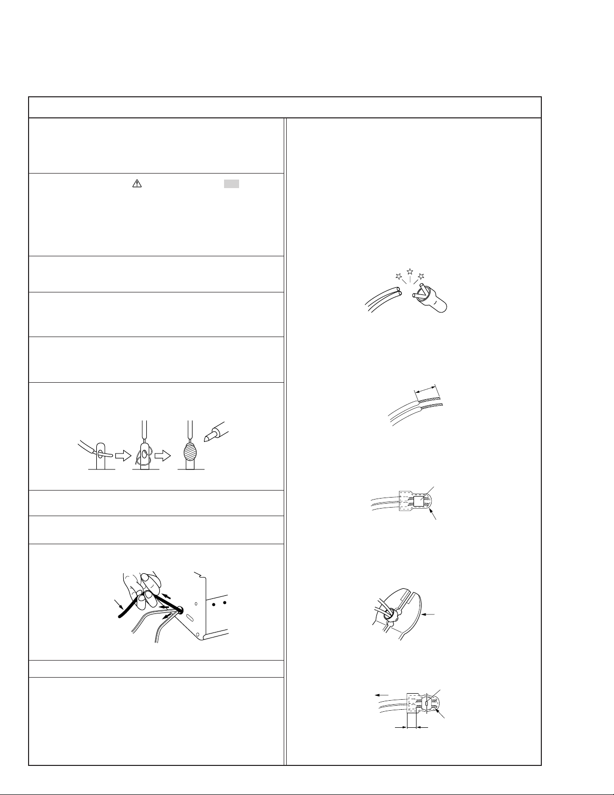
12. Crimp type wire connector
In such cases as when replacing the power transformer in sets
where the connections between the power cord and power
transformer primary lead wires are performed using crimp type
connectors, if replacing the connectors is unavoidable, in order to prevent safety hazards, perform carefully and precisely
according to the following steps.
1) Connector part number : E03830-001
2) Required tool : Connector crimping tool of the proper type
which will not damage insulated parts.
3) Replacement procedure
(1) Remove the old connector by cutting the wires at a point
close to the connector.
Important : Do not reuse a connector (discard it).
cut close to connector
Fig.3
(2) Strip about 15 mm of the insulation from the ends of
the wires. If the wires are stranded, twist the strands to
avoid frayed conductors.
15 mm
Fig.1
7. Observe that wires do not contact heat producing parts
(heatsinks, oxide metal film resistors, fusible resistors, etc.)
8. Check that replaced wires do not contact sharp edged or
pointed parts.
9. When a power cord has been replaced, check that 10-15 kg of
force in any direction will not loosen it.
Power cord
Fig.2
10. Also check areas surrounding repaired locations.
11. Products using cathode ray tubes (CRTs)
In regard to such products, the cathode ray tubes themselves,
the high voltage circuits, and related circuits are specified for
compliance with recognized codes pertaining to X-ray emission.
Consequently, when servicing these products, replace the cathode ray tubes and other parts with only the specified parts.
Under no circumstances attempt to modify these circuits.
Unauthorized modification can increase the high voltage value
and cause X-ray emission from the cathode ray tube.
Fig.4
(3) Align the lengths of the wires to be connected. Insert
the wires fully into the connector.
Fig.5
(4) As shown in Fig.6, use the crimping tool to crimp the
metal sleeve at the center position. Be sure to crimp fully
to the complete closure of the tool.
1.25
2.0
5.5
Fig.6
(5) Check the four points noted in Fig.7.
Not easily pulled free
Wire insulation recessed
more than 4 mm
Fig.7
Crimping tool
Crimped at approx. center
of metal sleeve
Conductors extended
1
S40888-01
Page 4
v
d'
d
Chassis
Power cord,
primary wire
Safety Check after Servicing
Examine the area surrounding the repaired location for damage or deterioration. Observe that screws, parts and wires have been
returned to original positions, Afterwards, perform the following tests and confirm the specified values in order to verify compliance with safety standards.
1. Insulation resistance test
Confirm the specified insulation resistance or greater between power cord plug prongs and
externally exposed parts of the set (RF terminals, antenna terminals, video and audio input
and output terminals, microphone jacks, earphone jacks, etc.). See table 1 below.
2. Dielectric strength test
Confirm specified dielectric strength or greater between power cord plug prongs and exposed
accessible parts of the set (RF terminals, antenna terminals, video and audio input and output
terminals, microphone jacks, earphone jacks, etc.). See table 1 below.
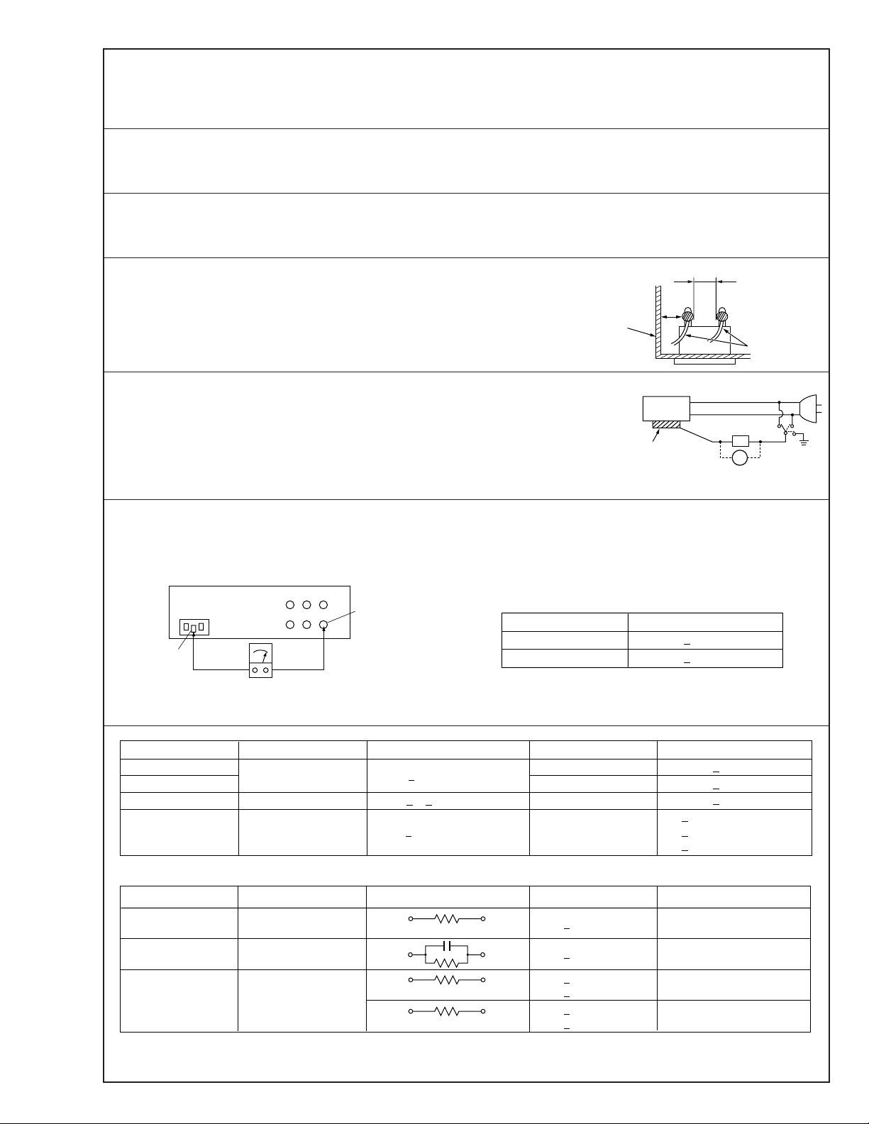
3. Clearance distance
When replacing primary circuit components, confirm specified clearance distance (d), (d’) between soldered terminals, and between terminals and surrounding metallic parts. See table 1
below.
Fig. 8
4. Leakage current test
Confirm specified or lower leakage current between earth ground/power cord plug prongs
and externally exposed accessible parts (RF terminals, antenna terminals, video and audio
input and output terminals, microphone jacks, earphone jacks, etc.).
Measuring Method : (Power ON)
Insert load Z between earth ground/power cord plug prongs and externally exposed accessible parts. Use an AC voltmeter to measure across both terminals of load Z. See figure 9 and
following table 2.
Externally
exposed
accessible part
Z
V
Fig. 9
ab
c
5. Grounding (Class 1 model only)
Confirm specified or lower grounding impedance between earth pin in AC inlet and externally exposed accessible parts (Video in,
Video out, Audio in, Audio out or Fixing screw etc.).
Measuring Method:
Connect milli ohm meter between earth pin in AC inlet and exposed accessible parts. See figure 10 and grounding specifications.
AC inlet
Earth pin
AC Line Voltage
100 V
100 to 240 V
110 to 130 V
110 to 130 V
200 to 240 V
Exposed accessible part
Milli ohm meter
Fig. 10
Region
Japan
USA & Canada
Europe & Australia R 10 MΩ/500 V DC
Region Load Z
Insulation Resistance (R)
≤
R 1 MΩ/500 V DC
≥≥
1 MΩ R 12 MΩ/500 V DC
≤
Table 1 Specifications for each region
Grounding Specifications
Region
USA & Canada
Europe & Australia
Dielectric Strength
AC 1 kV 1 minute
AC 1.5 kV 1 miute
AC 1 kV 1 minute
AC 3 kV 1 minute
AC 1.5 kV 1 minute
(Class 2)
(Class 1)
Grounding Impedance (Z)
≤
Z 0.1 ohm
≤
Z 0.5 ohm
Clearance Distance (d), (d')
≤
d, d' 3 mm
≤
d, d' 4 mm
≤
d, d' 3.2 mm
≤
d 4 mm
≤
d' 8 mm (Power cord)
≤
d' 6 mm (Primary wire)
a, b, cLeakage Current (i)AC Line Voltage
100 V
110 to 130 V
110 to 130 V
220 to 240 V
Note: These tables are unofficial and for reference only. Be sure to confirm the precise values for your particular country and locality.
Japan
USA & Canada
Europe & Australia
Table 2 Leakage current specifications for each region
1 kΩ
0.15 µF
1.5 kΩ
2 kΩ
50 kΩ
2
≤
i 1 mA rms Exposed accessible parts
≤
i 0.5 mA rms
≤
i 0.7 mA peak
≤
i 2 mA dc
≤
i 0.7 mA peak
≤
i 2 mA dc
Exposed accessible parts
Antenna earth terminals
Other terminals
S40888-01
Page 5
SECTION 1
DISASSEMBLY
1.1 BEFORE ASSEMBLY AND DISASSEMBLY
1.1.1 Precautions
1. Be sure to disconnect the power supply unit prior to mounting and soldering of parts.
2. Prior to removing a component part that needs to disconnect its connector(s) and its screw(s), first disconnect the
wire(s) from the connector(s), and then remove the screw(s).
3. When connecting/disconnecting wires, pay enough attention not to damage the connectors.
4. Be careful in removing or handling the part to which some
spacer or shield is attached for reinforcement or insulation.
5. When replacing chip parts (especially IC parts), first remove
the solder completely to prevent peeling of the pattern.
6. Tighten screws properly during the procedures. Unless
specified otherwise, tighten screws at a torque of 0.196N•m
(2.0kgf•cm).
1.1.2 Assembly and disassembly
[Example]
STEP
No.
[1]
LOWER CASE ASSEMBLY
[2]
B/W VF ASSEMBLY
[3]
TOP OPE UNIT
[4]
CASE COVER(S) ASSEMBLY
CASE COVER(M) ASSEMBLY
PART
Fig.
No.
Fig.C1
Fig.C2
POINT
8(S1),CN1a,b,c
3(S2)
CN3,L3a,2(L3b)
(S4),2(L4)
NOTE
-
-
-
-
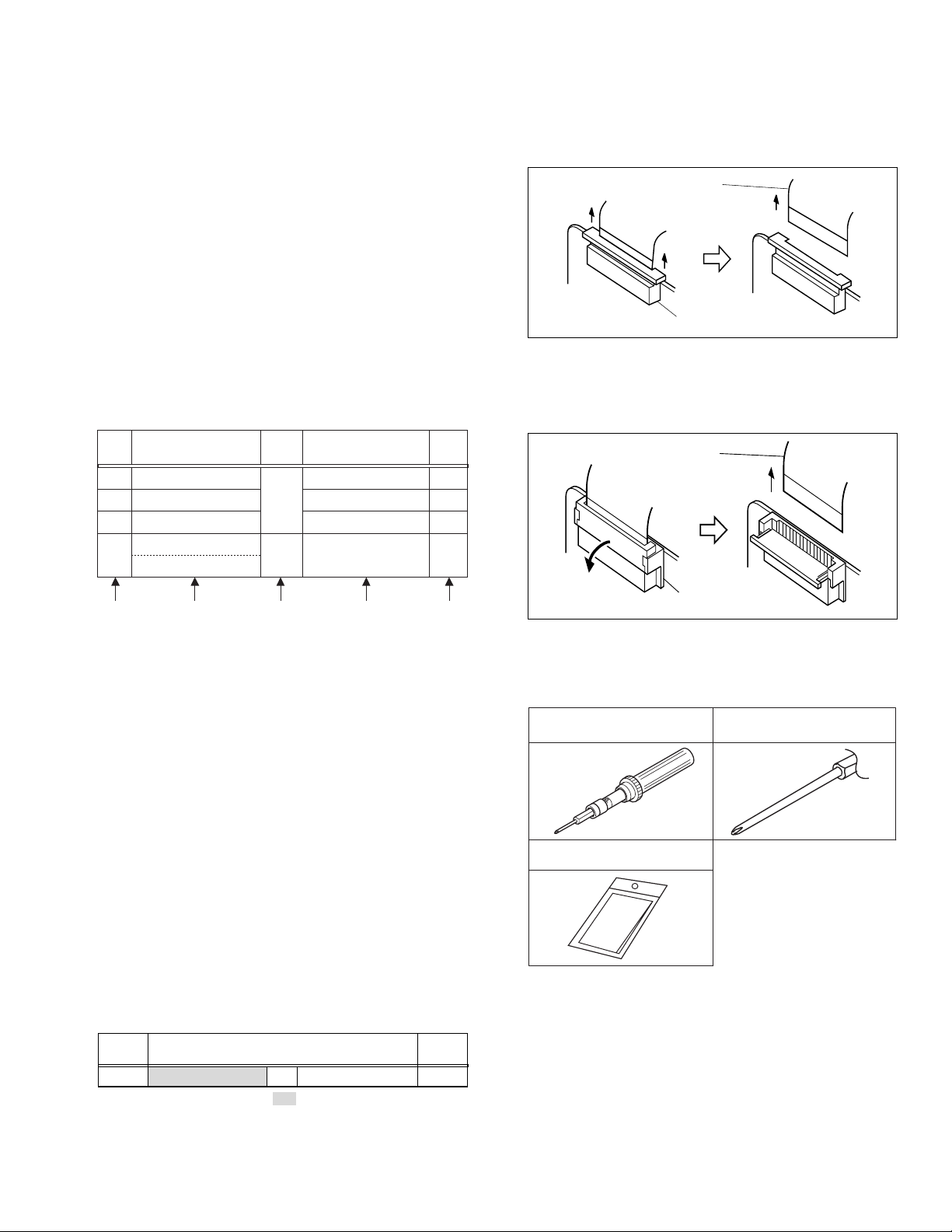
1.1.4 Disconnection of Connectors (Wires)
Pull both ends of the connector in the arrow direction, remove
the lock and disconnect the flat wire.
Flat wire
Connector
Fig. 1-1-1
Extend the locks in the direction of the arrow for unlocking and
then pull out the wire. After removing the wire, immediately
restore the locks to their original positions because the locks
are apt to come off the connector.
Flat wire
(4) (5)(2) (3)(1)
(1) Order of steps in Procedure
When reassembling, preform the step(s) in the reverse order. These numbers are also used as the identification (lo-
cation) No. of parts Figures.
(2) Part to be removed or installed.
(3) Fig. No. showing Procedure or Part Location.
C = CABINET
D = CAMERA AND BOARD ASSEMBLY
(4) Identification of part to be removed, unhooked, unlocked,
released, unplugged, unclamped or unsoldered.
P = Spring
W = Washer
S = Screw
* = Unhook, unlock, release, unplug or unsolder.
2(S3) = 2 Screws (S3)
CN = Connector
(5) Adjustment information for installation.
1.1.3 Destination of connectors
Two kinds of double-arrows in connection tables respec-
tively show kinds of connector/wires.
↔ : Wire
⇔ : Flat wire (FPC, FFC)
[Example]
CONN.
No.
CN1a MAIN CN27 ↔ SPEAKER – 2
CONNECTOR
Pin No.
Remove the parts marked in .
Connector
Fig. 1-1-2
1.1.5 Tools required for disassembly and assembly
Pull both ends of the connector in the arrow direction, remove
the lock and disconnect the flat wire.
1
3
Torque driver
YTU94088
Cleaning cloth
KSMM-01
2
Bit
YTU94088-003
Fig. 1-1-3
1. Torque driver
Be sure to use to fastening the mechanism and exterior parts
because those parts must strictly be controlled for tightening torque.
2. Bit
This bit is slightly longer than those set in conventional
torque drivers.
3. Cleaning cloth
Recommended cleaning cloth to wipe down the video
heads, mechanism (tape transport system), optical lens surface.
1-1
Page 6

1.2 ASSEMBLY AND DISASSEMBLY OF CABINET PARTS
1.2.1 Disassembly flow chart
This flowchart indicates the disassembly step for the cabinet
parts and board assembly in order to gain access to item(s)
to be serviced. When reassembling, perform the step(s) in reverse order.
[1]
[2]
[3]
[4]
[5]
[6]
[7]
[8]
[9]
[10]
[11]
LOWER CASE ASSY
C. COVER ASSY
C. COVER INSIDE
BATT. COVER ASSY
BATT. CASE ASSY
UPPER CASE
FRONT COVER SA
FRONT FRAME ASSY
OP ASSY (inc. CCD BOARD ASSY)
MAIN BOARD ASSY
SHIELD PLATE
1.2.2 Disassembly method
STEP
No.
[1]
[2] C.COVER ASSY 1(S2), 2(L2) –
[3] C.COVER INSIDE 4(L3) –
[4] BATT. COVER ASSY 2(L4) –
[5] BATT. CASE ASSY 4(S5), 2(L5) –
[6] UPPER CASE 1(S6), 2(L6) –
[7] FRONT COVER SA 2(S7), 2(L7), CN8 –
[8]
[9] OP ASSY 2(S9), CN22 –
[10] MAIN BOARD ASSY
[11] SHIELD PLATE 2(S11) –
[12] MECHANISM ASSY 3(S12), 2(L13) –
CONN.
No.
CN8 MAIN CN8 ↔ MIC ASSY – 2
CN22 MAIN CN22 ⇔ CCD
CN1 MAIN CN1 ⇔ MECHANISM – 10
CN2 MAIN CN2 ⇔ MECHANISM – 14
CN3 MAIN CN3 ⇔ MECHANISM – 18
CN4 MAIN CN4 ↔ MECHANISM – 2
CN5 MAIN CN5 ⇔ MECHANISM – 11
CN7 MAIN CN7 ⇔ MECHANISM – 11
PART
LOWER CASE ASSEMBLY
FRONT FRAME ASSY
Fig.
No.
Fig.1-2-1
6(S1) –
2(S8) –
Fig.1-2-2
2(S10), CN1(C3),
2(SD10), CN2(F3),
CN3(A2), CN4(D2),
CN5(E3), CN7(B2)
CONNECTOR
POINT
CN5301
Remove the parts marked in .
NOTE
–
Pin No.
16
[12]
MECHANISM ASSY
1-2
Page 7

i
j
THE SLIDE IS DONE IN THE SAME DIRECTION
AS THE SLIDE SWITCH OF MAIN PWB AND
LOWER CASE IS INSTALLED .
j
6
[1] LOWER CASE ASSY
i
4
(S1)
(S1)
(S1)
5
3
(S1)
2
(S1)
1
(S1)
[6] UPPER CASE
(L6)
2
11
[8] FRONT FRAME ASSY
14
(S8)
c
(S6)
e
e
[7] FRONT COVER SA
(S7)
12
(L7)
(L2)
2
[3] C.COVER INSIDE
[5] BATT.CASE ASSY
(S5)
8
g
(S5)
9
h
(L4)
2
7
(S5)
f
g
(L5)
4
(L3)
k
h
7
k
(S2)
b
c
13
(S7)
a
a
b
15
(S8)
d
(L7)
d
[2] C.COVER ASSY
CN8
A
A
DRAWING FOR MIC WIRE ARRANGEMENT.
THE SLACK OF WIRE
IS PROCESSED IN
THIS PART AS SHOWN
IN FIGURE.
WIRE PASSED THE LOWER
f
A SIDE VIEW
IC1601
SIDE OF THIS RIB.
THE INDSIDE OF
THIS BOSS IS PASS.
SO AS NOT TO PUT MIC WIRE ON IC601,
FIGURE IS PROCESSED TO A ROLL DOWNWARD.
[9] OP ASSY
Inc. CCD BOARD ASSY
i
CN22
i
(S5)
10
[4] BATT.COVER ASSY
(L5)
A
CONFIRM TERMINALS ARE CAUGHT IN
THIS HOOK WUEN BATT.CASE ASS'Y
IS INSTALLED.
17
(S9)
16
(S9)
WRXXX
Fig. 1-2-1
1-3
Page 8

[10] MAIN BOARD ASSY
18
CN2
(S10)
2
(SD10)
F3
19
(S10)
NOTE THE UNDERMENTIONED CONYENT WHEN SOLDERING.
A
A2
B2
CN3
CN7
CN5
CN1
CN4
E3
C3
D2
SOLDER ALL SURROUNDINGS
OF TERMINALS
A SIDE VIEW
23
(S12)
ATTACH TERMINALS.
FRAME
TERMINALS ARE INSTALLED IN THE
POSITION OF FIGURE .
IT HANGS IT
IT HANGS IT
A
INSERT TERMINAL 1 IN
THE INTERIOR , SURELY .
FRONT COVER SA
FRONT COVER ASSY
TERMINAL 3
TERMINAL 2
A SIDE VIEW
IT PUTS THE
POINT IN THE
HOLE .
TERMINAL 2 AND TERMINAL 3 HANG
ON THE HANGING PART , AND PUT
THE TERMINAL POINT AT THE END .
22
(S12)
FRAME ASSY
a
c
b
F1
F2
[12] MECHANISM ASSY
24
(S12)
b
e
MIC CAP
B1
A1
B2
A2
C1
E1
D1
d
E2
[11] SHIELD PLATE
C2
D2
CUSHION(ECM)
MIC ASSY
CUSHION
TAP SCREW x3
e
C2
C3
E2
F2
F3
A1
a
E3
21
(S11)
20
(S11)
CUSHION(ECM)
MIC ASSY
MIC IS INSERTED IN THE
INTERIOR OF MIC (CUSHION) ,
AND MIC IS COVERED WITH
MIC (CUSHION) .
MIC CAP
PART A OF MIC (CUSHION)
IS DRAWN OUT FROM THE HOLE .
DITCH PART B IS MADE TO
ENTER AROUND ALL THESE PARTS .
B1
c
CUSHION
THE CONNECTOR OF MIC IS PUT OUT
FROM THE INSIDE OF CUSHION
OUT SIDE THROUGH THIS SLIT PART .
c
MIC CAP
a
a
CONNECTION PART OF WIRE
IS MADE TO COME NEAR IS
THIS DITCH .
COVER MIC CAP WITH CUSHION
b
WHILE DRAWING OUT MIC WIRE
FROM CUSHION .
c
THE RIB OF MIC CAP IS PUT
OUT FROM PART a , PART b ,
AND PART c .
MIC CAP IS COVERED WITH
THE RABBER FRAME OF CUSHION .
b
D1
C1
d
E1
1-4
F1
Fig. 1-2-2
Page 9

1.3 EMERGENCY DISPLAY Example (in case of the error number E01):
Whenever some abnormal signal is input to the mechacon CPU,
an error number (E01, as an example) is displayed in the electronic view finder. In every error status, such the message as
shown below alternately appear over and over.
E01
UNIT IN
SAFEGUARD MODE
E01
REMOVE AND
REATTACH BATTERY
• In an emergency mode, all operations except turning on/off the
POWER switch are ineffectual.
E. VF Symptom Mode when observed
E07 Short circuit of capstan MDA Power ON
E06 CAPSTAN FG input absent CAPSTAN rotation
E04 DRUM FG input absent DRUM rotation
E03 SUPPLY REEL FG input absent REC, PLAY, SEARCH, FF/REW
E02 Mode control motor rotates for more than 6.0 sec UNLOADING without shift to next
UNLOADING
mode.
E01 Mode control motor rotates for more than 6.0 sec LOADING without shift to next mode. LOADING
E00 Overtime the programming transaction REC, PLAY
1.4 TAKE OUT CASSETTE TAPE
In the event that the set enters the emergency mode as it is
loaded with a cassette tape and the cassette tape cannot be
ejected with the EJECT button, manually, take it out of the set
according to the following procedure.
NOTE :
• If the mechanism comes into the unloading mode as the cassette tape is not held by hand, it results in tape damage.
(1) Disconnect the set from the power source.
(2) Remove the UPPER CASE. (refer to "1.2 ASSEMBLY
AND DISASSEMBLY OF CABINET PARTS".)
(3) Connect a jumper wire to each pole of the LOADING
MOTOR as shown by the magnified view (Fig. 1-4-1).
(4) While holding down the cassette housin g by hand, con-
nect the jumper wires to a battery to run the mechanism
to the EJECT position four unloading. If this unloading
operation is performed as the cassette housing is not
held down by hand, the front lid of the cassette may damage the tape when it is ejected.
(5) For taking in the slack of the tape, run the mechanism to
the EJECT position as the front lid of the cassette is left
open, and turn the TAKE-UP GEAR in the forward direction to wind up the tape. After confirming that the tape
has completely been wound up and the supply reel is
idling, take the cassette tape out of the cassette housing
(NTSC)
BATTERY
(DC1.5V)
MAGNIFIED VIEW
.
b
TAKE-UP GEAR
Fig.1-4-1
1-5
Page 10

1.5 SERVICE NOTE
Symbol No.
Removing order of screw
Place to stick screw
Reference drawing
Screw tightening torque
Symbol No.
Removing order of screw
Place to stick screw
Reference drawing
Screw tightening torque
< NOTE >
1) : : Don’t reuse the screw, because screw lock bond was applied to them.
2) Pay careful attention to tightening torque for each screw.
I : 0.196N·m (2.0kgf·cm) II : 0.118N·m (1.2kgf·cm) III : 0.204N·m (2.08kgf·cm)
[1] [2]
[11] [12][10]
[5] [9][6] [7] [8]
II
I III I
II
Fig.1-3-1
Fig.1-3-2
1.3 DISASSEMBLY/ASSEMBLY OF CABINET PARTS AND BOARD ASSEMBLY
1234567891011121314151617
18 19 20 21 22 23 24
Use the following chart to manage to screws.
Table 1-5-1
1-6
Page 11

3.1 PREPARATION
SERVICE
SUPPORT
SYSTEM
RS232C
COM PORT
PC CABLE
PERSONAL
COMPUTER
MENU
DC POWER
SUPPLY
DC6.3V
GND
COVER(JIG)
JIG CONNECTOR
CABLE
CN25
RED
TO RXD
WHITE
BLACK
TO TXD
TO BATT+
TO GND
TO GND
JIG CONNECTOR
COMMUNICATION CABLE
(1) Precaution
NOTE:
This model uses a dry cell as power supply. (can not
use AC adapter.)
Therefore, when adjusting, use DC POWER SUPPLY
and supply 6.3V to JIG connector.
This model does not contain adjustment controls (VR).
General deck system, camera system and monitor system
adjustment are not required. However, if MAIN board need
replacement, please use original EEP ROM on to new
board. Then adjustment are not required. And if parts such
as the following need replacement, special computerized
adjustment are required. 3.4.1 ELECTRICAL ADJUSTMENT WITH PERSONAL COMPUTER is setup and it adjusts using a service support system. Please contact to
JVC Service for detail information.
• OP BLOCK
• EEP ROM (IC102 of MAIN board)
• MONITOR
In the event of malfunction with electrical circuits, troubleshooting with the aid of proper test instruments most be
done first, and then commence necessary repair, replacement and adjustment, etc.
a) In case of wiring to chip test points for measurement,
use IC clips, etc. to avoid any stress.
b) Since connectors are fragile, carefully handle them in
disconnecting and connecting.
c) Short circuit between operation unit and DECK chas-
sis.
(2) Required test equipment
a) Color TV monitor.
b) DC power supply
c) Oscilloscope (dual-trace type, observable 100 MHz
or higher frequency)
• It is recommended to use one observable 300 MHz
or higher frequency.
d) Digital voltmeter
e) Frequency counter (with threshold level adjuster)
f) Personal computer
SECTION 3
ADJUSTMENT
(3) Connection
When adjusting, connect each required equipment(s)
shown in figure.
Fig. 3-1-1
3-1
Page 12

3.2 TOOLS REQUIRED FOR ADJUSTMENT
Alignment tape
1
Cassette torque meter
3
5
7
9
PUJ50431-2
INF adjustment lens
YTU92001B
Gray scale chart
YTU94133A
INF lens holder
YTU94087
MHP-C
Alignment tape
2
4
PTU94002-2
6
YTU92001-111
Color bar chart
8
10
YTU94133C
Light box assembly
YTU93096A
MHP-LC
Roller driver
Conn. ring
1,2. Alignment tape
To be used for check and adjustment of interchangeability of
the mechanism.
(Video: Color bar signal, Audio: Non-signal)
3. Cassette torque meter
This is used to cheek the back tension and play torque during
mechanism adjustment.
4. Roller driver
To be used to turn the Roller driver to adjustment of the linearity of playback envelope.
5.INF adjustment lens
To be used for adjustment of the camera system. For the usage of the INF adjustment lens, refer to the Service Bulletin
No. YA-SB-10035.
6.Conn. ring
The connector ring to attach the INF lens to the head of the OP
lens. For the usage of the Conn.ring.
7.Gray scale chart
To be used for adjustment of the camera system. For the usage of the INF adjustment lens, refer to the Service Bulletin
No. YA-SB-10035.
8.Color bar chart
To be used for adjustment of the camera system. For the usage of the INF adjustment lens, refer to the Service Bulletin
No. YA-SB-10035.
9.INF lens holder
To be used together with the Camera stand (11) for operating
the Videocamera in the stripped-down condition such as the
status without the exterior parts or for using commodi ties that
are not yet conformable to the interchangeable ring. For the
usage of the INF lens holder, refer to the Service Bulletin No.
YA-SB-10035.
11 12
13
Camera stand
YTU93079
Communication cable
YTU93107A
PC cable
QAM0099-002
14
1615
Fig.3-2-1
Jig connector cable
YTU93082G
Service support system
YTU94057-65
Cleaning cloth
KSMM-01
3-2
Page 13

10.Light box assembly
To be used for adjustment of the camera system. For the usage of the Light box assembly, refer to the Service Bulletin No.
YA-SB-10035.
11.Camera stand
To be used together with the INF adjustment lens holder. For
the usage of the Camera stand, refer to the Service Bulletin
No. YA-SB-10035.
12. Jig connector cable
To be connected to the Jig connector jack of the main board
and used for measurement and adjustment.
MAIN CN25 JIG BOARD (LABEL)
AL_L3.2V 1 1 AL_L3.2V
MCU_RST 11 2 BATT+
BATT+ 2 3 BATT+
V_TP_FM 12 4 C_OUT
BATT+ 3 5 DIAL_PB
V_FF 13 6 Y_OUT
C_OUT 4 7 GND
PB_CTL 14 8 GND
DIAL_PB 5 9 GND
REG_4.8V 15 10 V_OVL
Y_OUT 6 11 MCU_RST
AO_SIG_J 16 12 V_TP_FM
GND 7 13 V_FF
TXD 17 14 PB_CTL
GND 8 15 REG_4.8V
RXD 18 16 AO_SIG_J
GND 9 17 TXD
JIGCN_SW 19 18 RXD
V_OVL 10 19 JIGCN_SW
VPP_7.8V 20 20 VPP_7.8V
Fig.3-2-2
13.Communication Cable
Connect the Communication cable between the PC cable and
Jig connector cable when performing a PC adjustment.
14.Service support system
To be used for adjustment with a personal computer. Software
can be downloaded also from JS-net.
15.PC cable
To be used to connect the Videocamera and a personal computer with each other when a personal computer issued for adjustment.
16.Cleaning cloth
Recommended the Cleaning cloth to wipe down the video
heads, mechanism (tape transport system), optical lens surface.
3.3 MECHANISM ADJUSTMENT
3.3.1 TAPE TRANSPORT ADJUSTMENT
Mechanism adjustment is needed when DRUM ASSEMBLY or a
part of the tape transport system is replaced. To protect tapes
from damage, first clean the tape transport system, next confirm
that nothing is wrong with the tape transport system by using a
tape that can be disposed of, and then perform adjustment with
alignment tape. Some exterior parts should be removed before
some adjustment procedures, depending on the procedures.
POLE BASE (SUP)
(GUIDE ROLLER)
POLE BASE (TU)
(GUIDE ROLLER)
TU GUIDE
POLE
A/C HEAD
ASSEMBLY
TENSION
POLE
PINCH
ROLLER
Fig.3-3-1
3.3.2 Back tension
Remove the exterior parts attached to CASSETTE HOUSING
ASSEMBLY so that scales of CASSETTE TORQUE METER can
be read.
• CASE COVER(S),(M) ASSEMBLY
• C. COVER INSIDE
CASSETTE TORQUE METER
Fig.3-3-2
(1) Set a cassette torque meter onto the deck and measure the
back tension in standard PB mode to confirm that the back
tension is 0.97x10
-3
- 1.71x10⁻³ N•m.
(2) If not, replace the tension band.
When the value widely fluctuates in the measurement,
replace the SUPPL Y REEL DISK.
(3) With the CASSETTE TORQUE METER, confirm that the
play torque is 1.47x10
-3
- 2.45x10⁻³ N•m.
If necessary, replace the center pulley unit.
3-3
Page 14

BACK TENSION
0.97x10
(10-17gf·cm)
-3
- 1.71x10⁻³ N•m
PLA Y T ORQUE
1.47x10
-3
- 2.45x10⁻³ N·m
(15-25gf·cm)
Fig.3-3-3
3.3.3 Tape pattern
Remove the exterior parts attached to the UPPER CASE
ASSEMBL Y so that the guide roller beside the DRUM ASSEMBLY
can be rotated.
• LOWER CASE ASSEMBLY
• TOP OPE UNIT
• CASE COVER(S),(M) ASSEMBLY
• UPPER CASE (S),(M) ASSEMBLY
NOTE:
In performing adjustment, it is recommended that LOWER
CASE ASSEMBLY and TOP OPE UNIT are attached to the
main body for better operation and safety.
NOTE:
To prevent the tape from damage, turn the guide rollers
slowly.
(7) By operating the tracking button (both in + and - directions)
in the manual tracking mode, vary the output level of the
FM waveform from maximum to minimum and vice versa to
confirm that the waveform varies nearly in a flat shape.
(8) When the FM waveform breaks in the level varying process,
subtly adjust the height of guide rollers at every breaking
point so that the waveform varies as flat as possible.
Repeat the above steps 6. and 7. several times to confirm
that the waveform is flat as a whole.
(9) Playback the SP stairstep signal of alighment tape and ad-
just the tracking control to maximize the FM waveform,
confirm that FM waveform variation is always flat.
(10) Record the signal and play it back in both of the SP and EP
modes, and confirm that the FM waveform is flat in both
modes.
NOTE:
Among the above-mentioned adjustment steps, the
items of No.9 and No.10 are needed for the EP model
only.
CH-2
1 field
FLATTEN WAVEFORM.
POLE BASE (TU)
(GUIDE ROLLER)
POLE BASE (SUP)
(GUIDE ROLLER)
ALIGNMENT TAPE
JIG CONNECTOR CABLE
MAIN CN25 - JIG BOARD
12PIN(V_TP_FM)
13PIN(V_FF)
Fig.3-3-4
(1) Remove the Cover (JIG) shown on Fig.3-4-1.
(2) Connect the JIG CONNECTOR CABLE to CN25 on the
MAIN BOARD ASSEMBLY as shown on Fig. 3-2-2.
(3) Observe signal at V_TP_FM with external trigger from
V_FF on the JIG CONNECTOR CABLE.
(4) Playback the SP stairstep signal of the alignment tape and
maximize the FM waveform by the tracking button.
(5) Set the tracking control to the center position by simulta-
neously pressing the tracking (-) and (+) buttons and maximize the FM waveform by the tracking button.
(6) If the observed FM waveform is not flat, adjust the height of
the SUPPLY of TAKE-UP GUIDE ROLLER with the roller
driver.
CAUSER BY WRONG HEIGHT
OF SUPPLY GUIDE ROLLER
CAUSED BY WRONG HEIGHT
OF TAKE-UP GUIDE ROLLER
Fig.3-3-5
CORRECT VARIATION OF WAVEFORM
BAD VARIATION OF WA VEFORM
Fig.3-3-6
(11) Through the above steps, confirm that there occur no wrin-
kling and damage in the tape around the PINCH ROLLER
and TU GUIDE POLE whenever the deck is in operation of
Loading/Unloading, Search Rewind and at mode change
from Search Rewind to play mode. If wrinkling or damage
in the tape occurs around the TU GUIDE POLE, adjust the
angle (slant) of the A/C HEAD to the tape. So that the tape
normally runs along the lower flange of the GUIDE POLE.
3-4
Page 15

3.3.4 A/C head height & azimuth
Remove the exterior parts attached to the UPPER CASE
ASSEMBLY so that the screws around the A/C HEAD
ASSEMBLY can be tighten or loosen.
• LOWER CASE ASSEMBLY
• TOP OPE UNIT
• CASE COVER(S),(M) ASSEMBLY
• UPPER CASE (S),(M) ASSEMBLY
• FRONT FRAME ASSEMBLY
NOTE:
In performing adjustment, it is recommended that LOWER
CASE ASSEMBLY and TOP OPE UNIT are attached to the
main body for better operation and safety.
(1) Remove the Cover (JIG) shown on Fig.3-4-1.
(2) Connect the JIG CONNECTOR CABLE to CN25 on the
MAIN BOARD ASSEMBLY.
(3) Connect the channel-1 scope probe to the audio output
(AO_SIG_J) and connect the channel-2 scope probe to PB
CTL.
(4) Playback the alignment tape.
(5) Set the tracking to its center range by pressing the (+) and
(-) tracking controls simultaneously.
(6) Adjust screws A , B and C approximately 45 degrees in the
same direction to obtain maximum audio output and CTL
signal levels.
(7) As a final fine adjustment, adjust screw B for minimum sig-
nal level fluctuation and screw C for maximum output sig-
nal level
3.3.5 Phase of control head (X value)
Note:
Remove the exterior parts attached to the UPPER CASE
ASSEMBLY so that the screws around the A/C HEAD
ASSEMBLY can be tighten or loosen.
(1) Connect the JIG CONNECTOR CABLE to CN25 on the
MAIN BOARD ASSEMBLY.
(2) Playback the SP stairstep signal of the alignment tape and
observe signal at V_TP_FM with external trigger from
V_FF on the JIG CONNECTOR CABLE.
(3) Operate the tracking button in the center and manual
tracking mode by pressing the tracking (+) and (-) buttons
and confirm that the FM output level is maximum at
the center position as shown in Fig. 3-3-9.
(4) If necessary, slightly loosen the setscrews D and E and
insert the Tweezers into the notch and guide hole to move
the A/C HEAD fully in the direction of the capstan to the
extent.
(5) Gradually move the A/C HEAD toward the drum to find the
position where the FM output level maximum for the first
time (a’ - b’ in Fig. 3-3-9).
(6) Fine adjust the phase of the A/C HEAD and tighten the
screws D and E at the point a.
A/C HEAD
INSERT THE
TWEEZERS
.
SCREW A
A/C HEAD
Fig.3-3-7
Fig.3-3-8
SCREW C
SCREW B
Audio
signal
Control
pulse
signal
SCREW D
SCREW E
Fig.3-3-8
A
FM OUTPUT
DIRECTION OF CAPSTAN
ADJUSTING
POINT
A/C HEAD PHASE
B
MAX
ZERO
DIRECTION OF DRUM
Fig.3-3-9
3.4 ELECTRICAL ADJUSTMENT
3.4.1 ELECTRICAL ADJUSTMENT WITH PERSONAL COMPUTER
• Electrical adjustment except for B/W VF ASSEMBLY is per-
formed by using PERSONAL COMPUTER. As for the cable
connection, see Fig. 3-1-1. Read README.TXT file to use the
software for SERVICE SUPPORT SYSTEM properly.
• Remove the COVER (JIG) to perform adjustment.
NOTE:
For the connection of the JIG CONNECTOR CABLE, refer to
Fig.3-1-1.
3-5
Page 16

VICTOR COMPANY OF JAPAN, LIMITED
12,3-chome,Moriya-cho,Kanagawa-ku,Yokohama,Kanagawa-prefecture,221-8528,JapanAV & MULTIMEDIA COMPANY.
Printed in Japan
0305 VP
 Loading...