

Page 1

VR-N100U
Video Disc Recorder
Users Manual v1.0
Page 2

VR-N100U USERS MANUAL
Contact Information
Please contact your VR-N100U reseller for all sales, service and technical support issues.
Copyright © 1998-2004 xStore. All rights reserved
All other companies and product names are trademarks of their respective holders.
Page 2 of 98 All Items Are Subject To Change Without Notice Feb. 2004 Rev 1.0
Page 3

VR-N100U USERS MANUAL
TABLE OF CONTENTS
1. INTRODUCTION ...........................................................................................................................................................7
1.1. Manual Organization....................................................................................................................................................8
1.2. What is an Appliance?.................................................................................................................................................8
1.3. VR-N100U Addresses Key Issues...............................................................................................................................8
1.3.1. Analog Systems...........................................................................................................................................................8
1.3.2. IP Cameras ...................................................................................................................................................................8
1.3.3. Digital Video Recorders (DVR’s).................................................................................................................................9
1.3.4. Software-Based Solutions...........................................................................................................................................9
1.3.5. The Solution…VR-N100U Security Appliance....................................................................................... ....................9
2. INSTALLING VR-N100U .............................................................................................................................................10
2.1. Before You Begin.......................................................................................................................................................10
2.2. What’s in the Box.......................................................................................................................................................10
2.3. VR-N100U Hardware Overview .................................................................................................................................11
2.3.1 Hardware Layout........................................................................................................................................................11
2.3.2 Embedded Industrial Server .....................................................................................................................................12
2.3.3 Storage Capacity........................................................................................................................................................12
2.3.4 LCD Panel with Keypad and LED Indicators ...........................................................................................................12
• LCD Panel ........................................................................................................................................................12
• Keypad.............................................................................................................................................................13
• LED Indicators.................................................................................................................................................13
2.3.5 Power Supply.............................................................................................................................................................14
2.4. Installing VR-N100U on the Network........................................................................................................................15
2.4.1. The Basic Installation................................................................................................................................................15
2.4.2. Step 1: Acquiring an IP Address...............................................................................................................................15
Method 1: VDRView *Preferred Choice*...................................................................................................................15
Method 2: LCD Panel and Keypad............................................................................................................................16
Method 3: EazyIP .......................................................................................................................................................18
Method 4: Set a Workstation IP Address .................................................................................................................18
2.4.3. Step 2: Using the VR-N100U Web Browser..............................................................................................................19
• Admin Name and Password...........................................................................................................................19
• Setup Wizard ...................................................................................................................................................19
2.4.4. Step 3: Rebooting Your VR-N100U ...........................................................................................................................20
2.4.5. Step 4: Setting Up the Backchannel.........................................................................................................................21
• Backchannel 10/100 Mbit Switch ...................................................................................................................21
• Networked Cameras........................................................................................................................................21
2.4.6. Where to Go From Here.............................................................................................................................................23
3. VR-N100U OVERVIEW ...............................................................................................................................................24
3.1. Getting to the VR-N100U Web Browser Interface....................................................................................................25
3.2. The VR-N100U Setup Wizard..................................................................................................................................... 25
3.2.1. Server Name...............................................................................................................................................................26
3.2.2. admin Password & admin Password Confirm.........................................................................................................26
3.2.3. Date, Time & Time Zone ............................................................................................................................................26
3.3. The Administration “System” Utilities.....................................................................................................................27
3.3.1. Managing Y our Devices.............................................................................................................................................27
3.3.2. General Settings ........................................................................................................................................................28
3.3.3. Managing Users and Groups....................................................................................................................................28
3.3.4. Time Keeper ...............................................................................................................................................................30
3.3.5. Server Event Log .......................................................................................................................................................30
3.3.6. Server Event Notification ..........................................................................................................................................30
3.3.7. Server Reboot ............................................................................................................................................................31
3.4. The Administration “Networks” Utilities..................................................................................................................32
3.4.1. Network Information..................................................................................................................................................32
3.4.2. Static IP Setup............................................................................................................................................................32
3.4.3. DHCP Server Option..................................................................................................................................................33
3.5. The Administration “Cameras” Utilities...................................................................................................................34
3.5.1. Search.........................................................................................................................................................................34
3.5.2. Camera Views (2, 4, 8, 16) .........................................................................................................................................36
Page 3 of 98 All Items Are Subject To Change Without Notice Feb. 2004 Rev 1.0
Page 4

VR-N100U USERS MANUAL
• Camera Name ..................................................................................................................................................36
• Camera Recording Status...............................................................................................................................36
• Auto Playback .................................................................................................................................................36
• Details ..............................................................................................................................................................37
• PTZ or Magnify ................................................................................................................................................37
• Pan/Tilt Arrows................................................................................................................................................38
• Zoom In/Out.....................................................................................................................................................38
• Configure.........................................................................................................................................................39
• Camera Problems............................................................................................................................................39
• Auto Centering for PTZ...................................................................................................................................39
3.5.3. Discover......................................................................................................................................................................39
3.5.4. Motion Log..................................................................................................................................................................40
3.5.5. ISO Files......................................................................................................................................................................40
3.5.6. Setup Motion Detection.............................................................................................................................................41
• Luminance Threshold.....................................................................................................................................41
• Minimum Object Size......................................................................................................................................41
• Noise Filter.......................................................................................................................................................41
• Reference Image Refresh Interval..................................................................................................................41
• Motion Detection Delay...................................................................................................................................41
3.5.7. Setup Camera-Level Security ...................................................................................................................................41
• No Access........................................................................................................................................................41
• Viewer Level.....................................................................................................................................................42
• Operator Level.................................................................................................................................................42
3.6. VR-N100U’s Toolbar...................................................................................................................................................43
3.6.1. Administration Icon ...................................................................................................................................................43
3.6.2. Browse Icon................................................................................................................................................................43
3.6.3. Appliances List Icon..................................................................................................................................................44
3.6.4. Search Icon.................................................................................................................................................................44
3.6.5. About Icon..................................................................................................................................................................44
4. MANAGING VR-N100U WITH VDRVIEW...................................................................................................................45
4.1. System Requirements ...............................................................................................................................................45
4.1.1. Recommended Configuration...................................................................................................................................45
4.1.2. Minimum Configuration.............................................................................................................................................46
4.2. Installing VDRView.....................................................................................................................................................46
4.3. Discovering VR-N100U Appliances..........................................................................................................................47
4.4. Logging into VR-N100U.............................................................................................................................................47
4.5. Definition of Toolbar Icons........................................................................................................................................49
Zerver Information… ......................................................................................................................................49
Set Zerver IP Address…................................................................................................................................49
Administer Zerver… .......................................................................................................................................49
Reflash Firmware on Zerver…......................................................................................................................50
View Large Icons............................................................................................................................................50
View Small Icons............................................................................................................................................50
View List .........................................................................................................................................................50
View Details....................................................................................................................................................50
Edit Remote VR-N100U List….......................................................................................................................50
Communication Settings… ...........................................................................................................................50
New View ........................................................................................................................................................51
Save View........................................................................................................................................................51
Open View ......................................................................................................................................................51
Page 4 of 98 All Items Are Subject To Change Without Notice Feb. 2004 Rev 1.0
Page 5

VR-N100U USERS MANUAL
Edit/Delete View.............................................................................................................................................52
Close View......................................................................................................................................................52
Launch Camera Control .................................................................................................................................52
Full Screen View............................................................................................................................................53
Back to Previous Page...................................................................................................................................54
Go Forward to Next Page..............................................................................................................................54
Refresh Page..................................................................................................................................................54
View VR-N100Us.............................................................................................................................................54
4.6. Definition of Menus....................................................................................................................................................55
4.6.1. File...............................................................................................................................................................................55
4.6.2. View.............................................................................................................................................................................55
• Large Icons......................................................................................................................................................55
• Small Icons & List ...........................................................................................................................................55
• Details ..............................................................................................................................................................55
4.6.3. VR-N100Us..................................................................................................................................................................56
• Load Camera List............................................................................................................................................56
• Refresh Camera List (Ctrl+F5)........................................................................................................................56
• Discover Cameras on All VR-N100Us…........................................................................................................56
• Enable Local Recording .................................................................................................................................56
• Video Archive Settings…................................................................................................................................56
4.6.4. Camera Views.............................................................................................................................................................57
4.6.5. Options .......................................................................................................................................................................57
• Reboot…..........................................................................................................................................................57
• Enable Discovery via Microsoft Browsing….................................................................................................57
• Enable Discovery via Remote Server List….................................................................................................58
• Edit Remote Zerver List… ..............................................................................................................................58
• Communication Settings… ............................................................................................................................59
• Refresh Settings..............................................................................................................................................59
• Refresh (F5) .....................................................................................................................................................60
• Camera Settings..............................................................................................................................................60
4.6.6. Help (About VR-N100U).............................................................................................................................................60
4.7. Definition of Navigation Tabs....................................................................................................................................61
4.7.1. Zerver Center..............................................................................................................................................................61
4.7.2. VR-N100Us..................................................................................................................................................................62
• Camera Preview ..............................................................................................................................................62
• VR-N100U Camera List ...................................................................................................................................62
• Filter Camera List............................................................................................................................................63
• Camera Status Legend....................................................................................................................................63
• Preview Camera Window................................................................................................................................63
• Camera Configuration.....................................................................................................................................63
• Advanced Settings..........................................................................................................................................64
• Preset Positioning...........................................................................................................................................64
• Clear Preview Panel Contents........................................................................................................................64
• Print Panel Contents.......................................................................................................................................64
• Discover...........................................................................................................................................................64
4.7.3. Web Connect..............................................................................................................................................................64
4.7.4. Monitor Cameras........................................................................................................................................................65
4.7.5. Search/Playback ........................................................................................................................................................67
4.7.6. Motion Log..................................................................................................................................................................68
4.7.7. Reflash........................................................................................................................................................................69
5. SUPPORTED DEVICES..............................................................................................................................................71
5.1. Hard Disk Drive Specifications.................................................................................................................................71
5.1.1. Configuring the Hard Drives.....................................................................................................................................71
5.2. Network IP Cameras ..................................................................................................................................................72
Page 5 of 98 All Items Are Subject To Change Without Notice Feb. 2004 Rev 1.0
Page 6

VR-N100U USERS MANUAL
• Advanced Settings for VN-C10U....................................................................................................................72
• Advanced Settings for VN-C11U....................................................................................................................73
• Advanced Settings for VN-C30U....................................................................................................................73
5.2.1. Testing Network IP Cameras.....................................................................................................................................74
5.3. Network Enablers.......................................................................................................................................................75
• Advanced Settings for VN-A1U......................................................................................................................75
5.3.1. Testing Network Enablers .........................................................................................................................................75
5.4. Switches .....................................................................................................................................................................76
6. TECHNICAL TIPS AND TROUBLESHOOTING.........................................................................................................77
6.1. Industrial Server Board.............................................................................................................................................77
6.1.1. Processor ...................................................................................................................................................................78
6.1.2. Memory.......................................................................................................................................................................78
6.1.3. Onboard A TAPI...........................................................................................................................................................78
6.1.4. Onboard SCSI.............................................................................................................................................................78
6.1.5. Onboard Dual Ethernet..............................................................................................................................................79
6.1.6. PCI Expansion Slot....................................................................................................................................................79
6.1.7. USB .............................................................................................................................................................................79
6.1.8. COM Port ....................................................................................................................................................................79
6.2. Jumper Settings.........................................................................................................................................................80
6.2.1. JP1: Flash Disk ..........................................................................................................................................................80
6.2.2. JP2: SCSI Termination...............................................................................................................................................81
6.2.3. JP3: CMOS..................................................................................................................................................................81
6.2.4. CN6: A TX Power Button.............................................................................................................................................81
6.2.5. CN8: Hardware Reset ................................................................................................................................................81
6.2.6. CN22: Software Reset................................................................................................................................................82
6.3. BIOS............................................................................................................................................................................82
6.4. Adaptec SCSI BIOS....................................................................................................................................................82
6.5. LED Panel with Keypad and LED Indicators............................................................................................................83
6.5.1. LCD Panel...................................................................................................................................................................83
6.5.2. Keypad........................................................................................................................................................................83
6.5.3. LED Indicators............................................................................................................................................................ 84
• Status...............................................................................................................................................................84
• Network............................................................................................................................................................84
• 10/100...............................................................................................................................................................85
• Drive.................................................................................................................................................................85
6.5.4. Entering the Address.................................................................................................................................................85
6.5.5. Renaming Y our System.............................................................................................................................................85
6.5.6. Rebooting...................................................................................................................................................................86
6.5.7. View Events................................................................................................................................................................86
6.5.8. Manual Reboot Status ...............................................................................................................................................86
6.6. Power Supply.............................................................................................................................................................87
7. GLOSSARY OF TERMS..............................................................................................................................................88
8. REGULATORY NOTICES, LICENSE A ND WARRANTY............................................................................................97
8.1. Limited Warranty........................................................................................................................................................97
8.2. Agency Certifications................................................................................................................................................97
EMISSIONS CERTIFICATIONS ..................................................................................................................................97
SAFETY CERTIFICATIONS........................................................................................................................................97
8.3. License Provisions ....................................................................................................................................................98
8.4. US Government Restricted Rights Notice ...............................................................................................................98
Page 6 of 98 All Items Are Subject To Change Without Notice Feb. 2004 Rev 1.0
Page 7

VR-N100U USERS MANUAL
1. INTRODUCTION
Since the terrorist attack on the United States back on September 11
important topic for most individuals and organizations. Companies that d id not have any security systems implemented are
now actively looking for the latest digital security solution. Others that currently have one in place are actively looking to
upgrade to a more advanced digital security solution.
The VR-N100U security appliance solution i s an all-inc lusive “black bo x” security appliance that d elivers all of th e component s
necessary to easily and securely implement an IP-based security solution. All of the networking, security, storage, and
management functionalities are included and preconfigured on each VR- N100U appliance. It is completely scalable and can
be implemented into any LAN or WAN environme nt. VR-N100U is the only solution that allows any securit y administrator to
monitor and manage one or more facilities from any where in th e world in real-time. T he VR-N100U is e ngineer ed to of fer new
levels of flexibility, reliability, scalability and performance to the security market.
In the following chapters you will see how the VR-N100U allo ws any individual or company to easil y incorporate and manage
the latest networked digital security technology without the need for “expert” personnel in the fields of n etworking, secur ity and
storage. The VR-N100U security appliances fit easily into any existing distributed computing environment of intelligent
networks. They are low profile, self-contained units that are easy to setup, install and administer. The appliances support
multiple protocols, including SMB, ADS, FTP, NFS, AFT, DHCP, and HTTP and can serve clients using most network
operating systems. They will connect to either 10BaseT or 100B aseTX networks with appropriate performance scaling. T heir
ability to function as servers independently of a file server means that they do not strain the file server resources, they
minimize the overall network congestion, and, even if the f ile server goes down, the VR-N100U security appliance remains
online.
The VR-N100U uses a comprehensive set of tools in a web browser interface to administer storage and security devices,
users and groups, and interact with a wide variety of net work operating systems. The integration of NT Domain and ADS
services provides convenient, user-friendly authentication, and a single-point user/group management. An additional
standalone enterprise tool, VDRView, makes viewing, managing all of the VR-N100Us on the network a breeze. Easily
monitor and manage anywhere from one up to hundreds of thous ands of VR-N100Us and cameras. The unlimited VDRView
user license that is included with the VR-N100U appliance eliminates th ose “unexpected” additional cost of ownership that is
common with most security products. With VR-N100U’s unique architecture, you can now install thousands of cameras without
impacting the performance on your main network. In addition to the nearly unlimited number of cameras that can be
supported, VR-N100U offers the unique auto-discovery of network cameras to elimin ate the cumbersome and time con suming
issues surrounding setting up any manufacturer’s IP-based digital network cameras. From a single software interface of
VDRView, the security administrator can now easily monitor, manage, and control an unlimited number of locations from
anywhere in the world.
th
of 2001, security has been placed as the most
Page 7 of 98 All Items Are Subject To Change Without Notice Feb. 2004 Rev 1.0
Page 8

VR-N100U USERS MANUAL
1.1. Manual Organization
The VR-N100U User’s Manual documents the newest network security appliance. It features the new VR-N100U Security
Technology on the VR-N100U industrial server board. It has been organized in a manner that will allow any individual or
organization to quickly and easily install, setup and manage the VR-N100U security appliance and its associated devices.
1.2. What is an Appliance?
An appliance is an intelligent server that does not require an operator to be physically at the device in order to setup or
manage the server. An appliance generally does not require a monitor, keyboard, or mouse to be physically attached as
access is done via a web browser or software utility. There are many advantages to an appliance. It is designed to do a
specific function or task. In regards to VR-N100U, it manages all cameras and stores t he captured video from those devic es.
An appliance also utilizes minimum physical space and can be installed nearly anywhere.
1.3. VR-N100U Addresses Key Issues
The security market is still dominated by traditional analog systems, but has been undergoing a transition from it s analogbased CCTV products to the newer digital IP-based products. There are limitations in th e analog systems that no longer exis t
with the digital products. However, the digital products have also created new inherent issues. Thanks to the innovative
architecture and implementation of VR-N100U, we has been able to address all of these old and new issues.
1.3.1. Analog Systems
The days of analog security systems are numbered. The security market has been undergoing a transition from its traditional
analog-based CCTV products to the newer digital IP-b ased products. Customers looking for security systems are turning to
digital solutions. There are many drawbacks and limitations surrounding an analog system.
Although VHS-quality video has accepted up to this point, the wide acceptance of DVD-Video in the consumer mark et place
has helped push the demand of customers to require the di gital vi de o format. Also, due to the inher ent physical char acteristics
of tape, the media degrades over usage and time. T he more often the tape is viewed or reused for r ecording, the poorer the
quality becomes on this media. If companies have a very long security retentio n period requ irement, then they would require a
controlled environment for storing their media as well as a scheduled duplication period in order to maintain the video at its
highest possible quality. With analog video, the qualit y is greatly compromised as it degragates with each generation copy.
The VHS tapes have a limited capacity for recording and are relatively bulky media. In some instances hundreds and
thousands of tapes may be used during a c ourse of the year, thus occupying a tremendous amount of physical space for
storage. Although it is relatively easy to s end a co p y of a V HS tape to anywhere in th e world, it is not as portable or durable as
sending a CD, DVD, or as fast as receiving an e-mail or URL to do wnload the video instantly. When trying to search a vide o
tape, it is not only a cumbersome sequentially task, it may take multiple people to go thr ough many tapes to try to locate the
data which they are looking for. All of this involves a lot of resources, time and mone y. Also, nearly all ana log systems requ ire
a dedicated central security room that is the final desti nation for all of the “homeruns.” In these traditional security rooms, yo u
can find tens and hundreds of monitors, multiplexers and VCR equipment that are utilized by a team of personnel monitori ng
activities and constantly replacing VHS tapes once the end of tape has been reached.
1.3.2. IP Cameras
The latest products to hit the security market are network IP cameras. These cameras are self-contained digital n etworked
devices that can be viewed via any web browser. They are very flexible and can be easily setup in any networking
environment. Some are fixed while others offer pan, tilt and zoom capabil ities and motion detection. There are a few new
issues that IP cameras face that did not exist with their analog cousins. IP cameras require resources and must be configured
like other networked devices (e.g. IP address, permissions, passwords, etc.). Therefore, setting up IP cameras is a ve ry time
consuming task as they all come with their own default settings and the interface between different models as well as
manufacturers will greatly differ. Security now becomes an issue as they are susceptible to hackers from outside and within
the company network similar to other networked devices. If you plan on viewing and/or c apturing video from IP cameras, then
it will directly impact the infrastructure as heavy bandwidth will be used by each IP camera on the net work. If there are enoug h
IP cameras on the network, they will eventually cripple the network by ea ting up all of the bandwidth. Some companies also
utilize network attached storage devices as a “bit bucket” to ca pture video from IP-based net work cameras. Once the storage
fills up, you must then manually delete the video to create additional space.
Page 8 of 98 All Items Are Subject To Change Without Notice Feb. 2004 Rev 1.0
Page 9

VR-N100U USERS MANUAL
1.3.3. Digital Video Recorders (DVR’s)
Digital Video Recorders or better known as “DVR’s” is the first attempt for companies to offer an alternative solution to the
traditional analog systems. By adding video capture cards to a PC , many companies are trying to use this type of solution to
replace the popular VCR as the means of capturing and storing the security video digitally. The video from analog cameras are
converted to a digital format and then stored onto hard disk drives. Once the hard drives fill up with video, the customer has
the option to manually archive any of the vide o to a CD or DVD disc as well as delete the captured video in order to make
space for newer data. These solutions cannot be implement ed into most existing net work infrastructures as the dev ices eat up
valuable bandwidth and network resources.
1.3.4. Software-Based Solutions
There are many software-based security products and most require Intel- compatible computers running Microsoft Windows
server operating systems. They offer the ability to capture video from analo g cameras with capture cards or from IP-based
network cameras as well as manage the video. These solutions c an become very complex as well as very costly as each
feature and function is normally broken into various software mo dules. In addition to the options, license costs per camera
and/or per user normally apply, and don’t forget about the Microsoft server licenses. Finally, hidden costs such as new
infrastructures and separate dedicated high-speed networks must be implemented to utilize these solutions, plus dedicated
personnel trained to use and maintain the security system. The cost of ownership is dr amatically incre ased for such solutions.
For companies with multiple locations, it becomes too expensive and an impossible situation to manage and maintain.
1.3.5. The Solution…VR-N100U Security Appliance
With each VR-N100U appliance, a dedicated RAID set of large capacit y hard disk drives for online storage is utilized and
occupies a very small 19” 1U form-factor footprint. Options are available to add additional hard disk drive storage or archivi ng
to other media such as CD, DVD and tape in a seaml ess automated manner provides the maximum flexibility for the VRN100U customer. Thus, the video could reside on non-volatile and random access write-once or rewritable media that has a
life expectancy of at least 50 years for pennies per gigabyte. There is no need for spec ial environments, large dedicated rooms
for media storage, rerecording of discs, or playback compatibility. VR-N100U also supports auto-discovery and configuring of
IP cameras as well as supports analog cameras via network encoders. The camera t ypes can be fixed, pan-tilt-zoom as well
as motion detection. Up to sixteen cameras can be supported by each VR-N100U appliance and completely scalable to
support the enterprise. As more cameras are needed, additional VR-N100U appliances can be implemented. Nearly an
unlimited number of VR-N100U appliances and their cameras can easily be managed from a single software interface.
Installation into existing network infrastructures is supported with minimal resources utili zed. A single IP address is required
for a VR-N100U appliance and 16 cameras. For larger and enterprise environme nts, we offer the ability to utilize our unique
dynamic IP addressing schema to associate a single IP address for an unlimited number of VR-N100U appliances and their
associated cameras. With hundreds and thousands of cameras simultaneously archivi ng video 24x7x365 in real-time at their
highest resolution and frame rate, there is literally no impact on the network bandwidth. Monitoring and managing the VRN100U security appliance can be done from an ywhere in th e world with an internet con nection a nd usin g either a web b ro wser
or the enterprise client software utility called VDRView. No hidden costs exist as un limited user license is included with each
VR-N100U security appliance.
Page 9 of 98 All Items Are Subject To Change Without Notice Feb. 2004 Rev 1.0
Page 10

VR-N100U USERS MANUAL
2. INSTALLING VR-N100U
This chapter covers all aspects for the VR-N100U installation, from the VR-N100U rackmount configuration to manually
acquiring an IP address. Some of the procedures described here may not be relevant to your spec ific installation. Simply skip
the section(s) that do not apply and move on to the next applicable section.
2.1. Before You Begin
WARNING
Disconnect the VR-N100U from its AC power sourc e before you connect or disco nnect cables, install or remove any
components. Failure to do so can result in personal injury or equipment damage that will NOT be covered under the
product’s warranty. Some circuitry on the VR-N100U can continue to operate even though the power switch is turned
off.
CAUTION
Electrostatic Discharge (ESD) can damage the VR-N100U components and devices. Configure the VR-N100U at an
ESD-controlled workstation. You must wear an anti-static wrist strap or equivalent accessories.
2.2. What’s in the Box
The VR-N100U Rackmount Solution includes the following items:
VR-N100U Rackmount System
¾ 19” 1U Rackmount Chassis
¾ Power Supply
¾ VR-N100U Industrial Server Board (VR-N100U OS & APP preinstalled)
¾ LED Display
¾ Multiple Hard Disk Drives (Configured as a RAID-5 set)
¾ Various Cables
VR-N100U Quick Installation Guide (Insert Sheet)
VR-N100U Companion CD (VDRView Application and Use rs Manual)
CAT5/CAT5e Ethernet Cable (Connecting the VR-N100U to the switch that is dedicated for the cameras)
Optional 24-port 10/100 Fast Ethernet Switch (Exclusively for camera backchannel and uses only 17 ports)
Page 10 of 98 All Items Are Subject To Change Without Notice Feb. 2004 Rev 1.0
Page 11
VR-N100U USERS MANUAL
2.3. VR-N100U Hardware Overview
The VR-N100U comes preconfigured in a 19” 1U Rackmount enclosure. The embedded industrial server board with
processor, heat sink, fan, memory, non-volatile flash disk and LCD displa y have all been installed and passed q uality control
prior to shipping. Although the design of the board is ver y compact, it provides all of the key standard components plus many
customized features. The VR-N100U board is the next gener ation industrial grade motherboard that was designed from the
ground-up with storage, performance and flexibility in mind. This all-in-one server board is the most powerful appliance
platform on the market, offering a vast array of onboard storage and conn ectivity components in a ver y small form-factor. The
latest VR-N100U operating system and applications are inst alle d and teste d on the no n-v olatile fl ash dis k. In ad ditio n, the har d
disk drives have also been tested and configured as a RAID-5 set prior to shipping for all VR-N100U 19” 1U Rackmount
Systems.
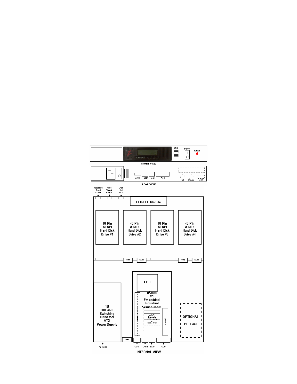
2.3.1 Hardware Layout
The custom 19” 1U Rackmount enclosure has been designed to provide easy installation for all of the VR-N100U hardware
components. The front-half is designed to integrate the LCD display, up t o four fixed hard drives, and optional slim CD/DVD
drive that is currently not supported by VR-N100U. The r ear-half of the enclosure is designed to integrate the high qualit y
power supply, industrial embedded server board and optional hard drive or expansion card. To ensure good ventilation to keep
the system cool, the VR-N100U hardware is designed to support air ventilation holes, five cooling fans and i ncludes custom
multi-drive cabling that offers minimum air flow restriction within the system.
Page 11 of 98 All Items Are Subject To Change Without Notice Feb. 2004 Rev 1.0
Page 12
VR-N100U USERS MANUAL
2.3.2 Embedded Industrial Server
The engine that runs the VR-N100U security appliance is based on the custom designed fourth generation embedded
industrial server motherboard. The Intel-based processor and memory are preconfigured on the VR-N100U. T he motherboard
comes fully equipped with storage in mind with multipl e onboard ATAPI/IDE Channels that offers the ability to support lar ge
number of peripherals. In addition to the massive number of ATAPI devices, it can also be equipped with an onboard SCSI
Channel with two less ATAPI Channels. The Adaptec Ultr a160-LVD/SE SCSI supports any SCSI-1, SCSI-2, SCSI-3, Narrow,
Ultra, Wide, Ultra Wide, LVD160, and LVD320-based devices. The onboard SCSI offers the ab ilit y for VR -N100U custo mers to
easily expand the total amount of RAID storages. The VR-N10 0U also comes standard with dual onboard 10/100 Network
Interface Connectors (NIC’s) for providing a higher level of flexibility, conn ectivity and functiona lity. LAN1 is des ignated for the
VR-N100U front-channel for connectivity to the company’s main network backbone while LAN2 is used as the VR-N100U
backchannel for managing up to 16 cameras. For additional e xpandability, an onboard 32-bit PCI Expansion Slot can to be
utilized for the optional Video Life Cycle Management function of VR-N100U. As most motherboards today come standard with
USB support, the VR-N100U is no different. The board also has the capability to support onboard USB. Finally, thanks to the
optimized and multi-threaded embedded Operating System and intelligent VR-N100U application installed on the non- volatile
flash disk, VR-N100U is able to achieve fastest performance.
2.3.3 Storage Capacity
The main difference between the various 19” 1U VR-N100U Rackm ount ap plia nce mode ls will be the am ount of on line s t orage
that the customer would like to have. The amount storage capacity will be dictated by the length of time (duration) required to
store the captured video. This calculation will be dictated by the number of cameras mana ged by VR-N100U (up to 16 per
unit), the resolution setting for each camera, as well as the recording method for each camera. As in dicated above, the VRN100U will be normally configured with at least four large capacity and fast performance ATAPI hard disk drives. These drives
will be part of a RAID-set, thus it is recommended that they are all of the same make, model and capacity.
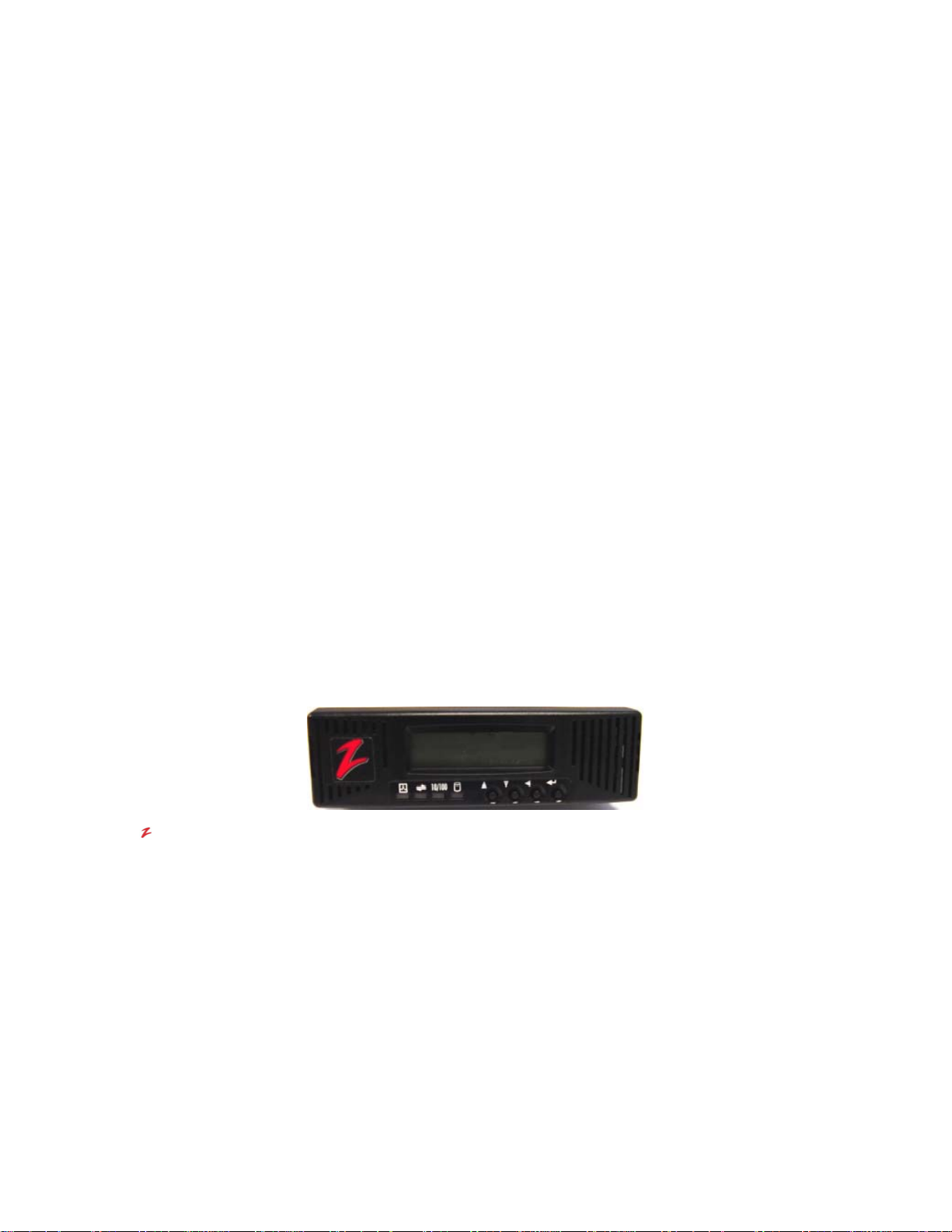
2.3.4 LCD Panel with Keypad and LED Indicators
The VR-N100U appliance is designed to utilize the LCD Display Panel, Keypad and LED Indicators. This LCD Display
supports 2-lines of 16 alphanumeric characters, has four (4) access buttons, and als o includes the four (4) LEDs that provide
important status information for various components. These are utilized by the VR-N100U to provide important information
regarding the current status of the appliance. These include the Status Activity, Network Activity (LAN1), 10/100 Network
Connection Status (LAN1), and Device Activity for all ATAPI and SCSI Channels. The phases of the li ghts provide information
about the operation of the VR-N100U.
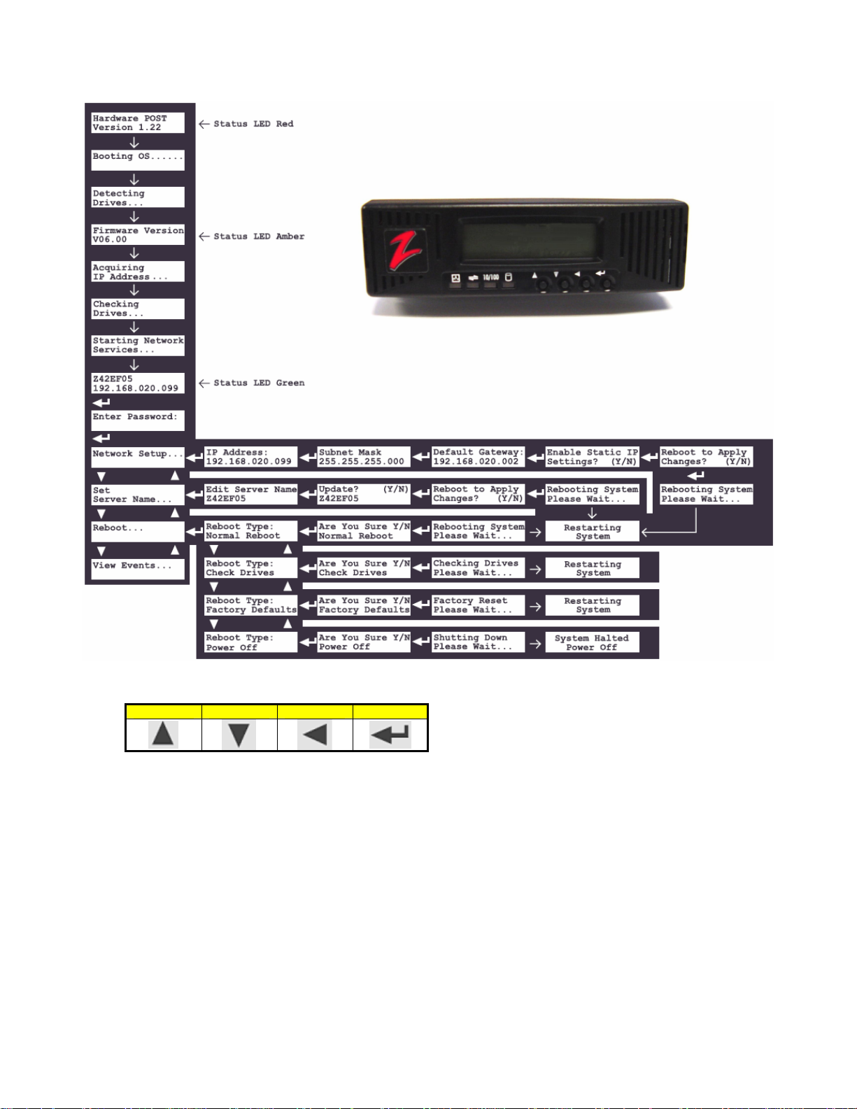
LCD Panel
When the VR-N100U starts up, the LCD display will b egin displa ying messages. It will keep you informed of th e
steps the system is going through during the boot up process and is summarized on the chart below. This
comprehensive display graphically illustrates the steps of each process that can be performed using the LCD
Panel.
The LCD Panel begins by displaying the message Hardw are POST with a version number on the second line
(POST stands for Power-On Self-Test). The Status LED (the first indicator light on the left) will display solid red.
As VR-N100U boots the OS (operating system) and detects the driv es, those messages will be display on the
Panel. When the boot up process goes into the next phase, the Status LED changes to solid amber and the
version number of the firmware is displayed on the Panel. The system then attempts to acquire an IP address,
checks the drives, and starts networking services. If a DHCP Server is running on the network, VR-N100U
dynamically acquires an IP address. The Status light turns solid green and the defa ult Server Name displays on
the LCD Panel with the IP address on the next line. T he Server Name and IP address will continue to display
until an event occurs on the VR-N100U, or the user pushes a key. This is called the Stead y State Display, and it
means everything is running. If the VR-N100U did not dynamically acquire an IP address, it will assign itself th e
address 10.10.10.10 and the Status light will slowly blink amber. When a VR-N100U comes up tens, it mean s
that a Static IP address must be assigned to the system before anything else ca n be done with it. You will need
to go your network admin and get an IP address, the Subnet Mask, and the address of the Default Gateway.
Page 12 of 98 All Items Are Subject To Change Without Notice Feb. 2004 Rev 1.0
Page 13
VR-N100U USERS MANUAL
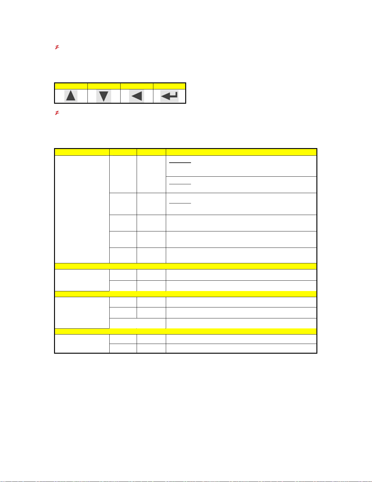
Keypad
Each key has a different function, illustrated by a directional arrow just above and to the left of the key. From left
to right, the first key is the Up key. The next key is the Down key. The third key is the Back key. And, the last
key, the key on the right, is the Enter key.
Up Down Back Enter
LED Indicators
The LEDs are identified by a keyword above each light on t he unit and by the complete name of the LED in the
following graphic. The LED lights can flash green, amber, o r red, each color in dicating a different state or activity
of the system. The chart below summarizes the LED indicators.
Status: The Status LED, the first light on the left, cycles through its power-on sequence as the VR-N100U boots up.
Network: The Network Activity LED flashes green when there is network traffic from an external source on LAN1, the
LED Label Color Aspect Description
Red Solid
Status
Network
Network Activity
(LAN1-Backbone)
10/100
Network Speed
(LAN1-Backbone)
Drive
Drive Activity
Amber Solid
Green Solid
Amber Flashing
Green/
Amber
Green Flashing Indicates that network traffic from an external source
Amber Flashing Indicates that the VR-N100U is transmitting
Amber Solid Your network speed is 10 Mbps.
Green Solid Your network speed is 100 Mbps.
Green Flashing An IDE drive is reading or writing data.
Red Flashing A SCSI drive is reading or writing data.
Blinking
No Light Indicates that there is no network link visible to the VR-N100U
It starts out solid red during self-test. Solid amber indicates the server is booting the OS and t he applic ation.
Solid green indicates the VR-N100U has successfully powered on a nd dynamically acquired a n IP address.
The Status light will remain solid green throu ghout normal operation. If the Status li ght slowly blinks amber,
VR-N100U has failed to dynamically acquire an IP address. You must simply use one of the four methods
outlined in the manual to manually acquire an IP addre ss. When VR-N100U is in the pr ocess of updating or
reflashing the VR-N100U firmware, the Status LED will flash quickl y between green and amber. Under no
circumstances should the process be cancelled or power be removed fr om the unit during the reflash. A
partial or terminated operation may result in a dysfunctional unit.
network backbone. When the Network LED flashes amber, it means the VR-N100U is transmitting
information between the cameras, storage and/or clients over the network.
Power-On
the self-test is completed, the LED transitions to amber and
continues the power-on process.
Power-Off
which power can be safely turned off on the VR-N100U
Power-On
has completed the self-test and is booting the OS and application.
Indicates that VR-N100U is completely initialized. It has acquired
and IP address and is operational.
Indicates that VR-N100U was unable to acquire an IP address. It
defaults to the address 10.10.10.10.
Indicated that VR-N100U is reflashing the firmware.
NEVER INTERRUPT THIS PROCESS!!!
: Solid Red during power-on indicates a self-test. When
: Solid Red during power-off indicates a safe halt, after
: Solid Amber during power-on indicates that VR-N100U
Page 13 of 98 All Items Are Subject To Change Without Notice Feb. 2004 Rev 1.0
Page 14

VR-N100U USERS MANUAL
10/100: The Network Speed LED will be either solid amber, or s olid green. Amber indicates the LAN1 front channel
network speed is 10 Mbps. Green indicates the LAN1 front channel network speed is 100 Mbps. Whe n the
LED is red, there is no network link visible to the server on LAN1.
Drive: The Drive Activity LED lights up whenever data is moving to or from an IDE device or SCSI device. A
flashing green light indicates an attached IDE drive is reading or writing data. A flashing red light ind icates a
SCSI device is reading or writing data. A flashing amber light indicates both IDE and SCSI devices are
active. The Drive Activity LED does not differentiate between reading and writing data.
NOTE: Only LAN1’s Network and 10/100 LED’s are only available on the LCD Display.
2.3.5 Power Supply
The VR-N100U board is also unique in that it has bee n designed to support the two most common types of power supplies
used today (AT and ATX). This flexibility will allow the board to be installed in nearly all enclosures. A powerful and high quality
ATX power supply is recommended and comes standard with all VR-N100U rackmount systems.
NOTE1: When selecting the AT X power adapter, do not forget to attach an ATX power switch to CN6 pin s et. This has
been already configured on the 19” 1U VR-N100U Rackmount Systems.
Page 14 of 98 All Items Are Subject To Change Without Notice Feb. 2004 Rev 1.0
Page 15

VR-N100U USERS MANUAL
2.4. Installing VR-N100U on the Network
BEFORE YOU BEGIN
As the Installer and/or Administrator of the VR-N100U, you are assumed to have a working kno wledge of TCP/IP and your
network. Make sure you have the following items before you begin the installation:
A TCP/IP Network
An Ethernet/Fast Ethernet Connection (backbone)
Available IP Address or DHCP Server on the Main Network
A CAT5/CAT5e Compliant Network Cables
VR-N100U Default Name (found on the VR-N100U enclosure label)
Workstation on the Network with a CD/DVD Drive and Web Browser on the same segment as the VR-N100U
2.4.1. The Basic Installation
VR-N100U requires three primary connections. The first is a con necti on to power the appliance. The second is a connection to
the company’s network backbone via LAN1 Ethernet port. Once VR-N100U is on the network, then the third connectio n will be
to the dedicated camera backchannel via LAN2 Ethernet port.
1. Using a standard CAT5/CAT5e twisted pair network cable, attach the VR-N100U to an Ethernet segment on your
company’s network via LAN1.
2. Connect the power cord to the VR-N100U rackmount enclosure and plug it in to a power strip, lin e conditioner or
UPS. The enclosure has an On/Off switch to control power. Proceed to turn the VR-N100U security appliance ON.
NOTE: At this time, we will concentrate on getting VR-N100U on your network. Once it has been successfully installed, th en
we will explain how to connect the network IP cameras to VR-N100U.
2.4.2. Step 1: Acquiring an IP Address
When the Status LED is blinking amber, it means the VR-N100U was unable to acquire an IP address dynamically. IP
addresses are obtained dynamically by means of one of three methods: D HCP, BOOT P, or RARP. If none of these IP address
assignment methods is available on your net work, the VR-N100U assigns itself a temporary IP a ddress of 10.10.10.10, or
tens. This is not a valid IP address, but it can be used long enough for you to see the VR-N100U on the network and to
change this IP address to a static IP address that is valid for your network. You can use one of the follo wing methods to
achieve that end and get the green Status light.
Method 1: VDRView *Preferred Choice*
Enclosed in the VR-N100U packaging should be a Companion CD. This disc is comprised of additional documentation and
software utilities. VDRView is documented in detail in Chapter 4 Managing VR-N100U with VDRView. VDRView is an
administrative enterprise application tool that discovers all of the VR-N100 Us on your local net work segment, remote servers,
and offers complete camera management from a Windows workstation. One of its functions is to assign static IP addresses to
VR-N100U. The detail instructions for installing VDRView from the VR-N100U Companion CD are detailed in section 4.2
Installing VDRView. This section describes how to use VDRView to assign an IP address.
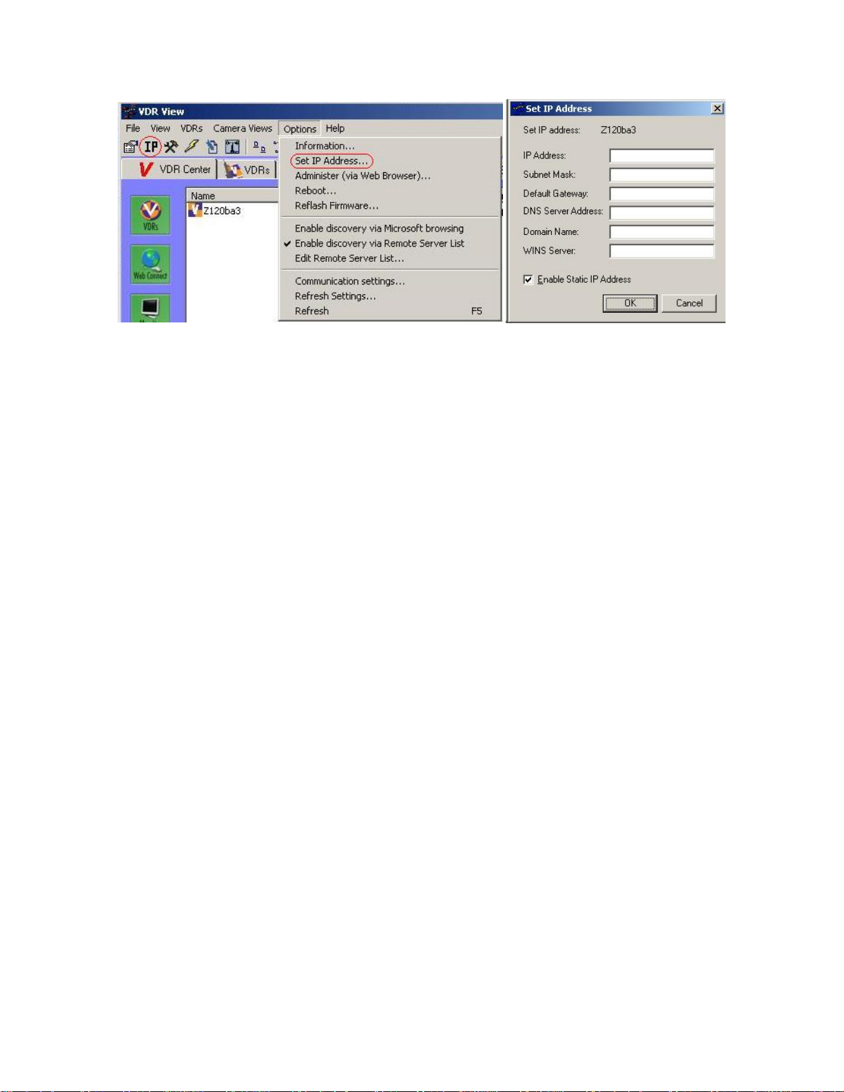
1. Install and launch the VDRView application.
2. Select (highlight) the VR-N100U from the list of discovered Zervers by clicking on it.
3. Click on the Set IP icon on the Toolbar, or select the Set IP Address option from the Options menu. It will
automatically prompt you with a login dialog box as this function is only available for users with administrator
privileges.
4. Once logged in, the Set IP Address dialog box will be displayed.
5. Set the appropriate addresses and click on the Enable Static IP address checkbox and click on the OK
button. This causes the VR-N100U to automatically reboot.
Page 15 of 98 All Items Are Subject To Change Without Notice Feb. 2004 Rev 1.0
Page 16
VR-N100U USERS MANUAL
Also, you can utilize the Web Connect page to log into the VR-N100U to setup the IP address. Details regarding thi s is listed
in section 3.4.2 Static IP Setup.
You can now skip the following Methods as VDRView has handled the entire process for you. You are ready to begin
exploring the features of VR-N100U in following sections.
Method 2: LCD Panel and Keypad
You can directly input the IP address to your VR-N100U using the LCD Panel and keypad. VR-N100U supports the LCD Panel
and Keypad, a hardware feature that is standard o n the VR-N100U. What will be r eferred to from here o n as the LCD Pane l is
a bezel that consists of an LCD Panel, a four-key keypad an d the four LED indic ator lights. The LCD Panel displays messages
about VR-N100U events and system alerts and accepts some VR-N100 U settings. The settings that ca n be inputted u sing the
LCD Panel include: the IP address, the Subnet Mask, the Default Gateway address, and the Server Name. In addition, the
LCD Panel can be used to reboot the VR-N100U.
When the VR-N100U starts up, the LCD Panel will begin displaying messages. It will keep you informed of the steps the
system is going through during the boot-up process, as shown in this graphic.
This comprehensive display graphically illustrates the steps of each process that can be performed using the LCD Panel. An
explanation of each process follows.
The LCD Panel begins by displaying the message Hardware POST with a version number on the second line (POST stands
for Power On Self Test). The Status LED (the first indicator light on the left) will display solid red. As VR-N100U boots the OS
(operating system) and detects the drives, those messages display on the Panel. When the boot-up pro cess goes into the next
phase, the Status LED changes to solid amber and the version number of the firm ware is displayed on the Pan el. The system
then attempts to acquire an IP address, checks the drives, and starts networking services. If a DHCP Server is running on th e
network, VR-N100U dynamically acquires an IP address. The Status light turns solid green and the default Server Name
displays on the LCD Panel with the IP addre ss on the ne xt line. T he Server Name a nd IP address will continue to displa y until
an event occurs on the VR-N100U, or the user pushes a key. This is called the Steady State Display, and it means all is well.
If the VR-N100U did not dynamically acquire an IP address, it will assign itself the address 10.10.10.10 and the Status light will
slowly blink amber. When a VR-N100U comes up tens, it means that a Static IP address must be assigned to the system
before anything else can be done with it. You will need to go your network admin and get an IP address, the Subnet Mask, and
the address of the Default Gateway.
Page 16 of 98 All Items Are Subject To Change Without Notice Feb. 2004 Rev 1.0
Page 17
VR-N100U USERS MANUAL
Each key has a different function, illustrated by a directional arrow just above and to the left of the key.
Up Down Back Enter
From left to right, the first key is the Up key. The next key is the Down key. The third key is the Back key. And, the l ast key,
the key on the right, is the Enter key. Follow the steps below to enter the addresses:
1. Press the Enter key. The LCD Panel will display the message Network Setup...
2. Press the Enter key. The Panel displays the IP Address entry screen. The cursor will be positioned at the location o f
the first digit in the first set of numbers. Use the Up and Down arrow keys (Up increments the number, Down
decrements it) to locate the first number in the IP address. When the c orrect number is displayed in t he first position,
depress the Enter key. The cursor advances to the next pos ition in the IP a ddress. Contin ue to use t he Up a nd Do wn
arrow keys to locate the numbers in the IP address, depressing the Enter key to accept each number. Use the Back
key to move the cursor one position to the left. Don’t forget, if the address you were given has only one or two digits
in any of the number sets of the address, use leading zeroes to pad the number set to three digits. For example, if the
IP address you were given is 195.182.30.4, enter 195.182.030.004 in the address fields. When you have finish ed an d
have verified that you entered the correct IP address, press the Enter key.
3. The Subnet Mask entry screen displays. Enter the Subnet Mask us ing the arrow keys as you did for the IP address.
When you have finished, press the Enter key.
4. The Default Gateway address entry screen di splays. Enter the address and press the Enter key.
Page 17 of 98 All Items Are Subject To Change Without Notice Feb. 2004 Rev 1.0
Page 18

VR-N100U USERS MANUAL
5. The next screen inquires if you want to Enable Static IP Setting and the other addresses you just entered. If you
select the Y, the addresses will be saved. If you select the N, the option to obtain the IP addr ess dynamically in that
same tool will be selected. Use the arrow keys to toggle between the Y and N. Press the Enter key t o accept your
selection.
6. The next screen that displays asks if you want to Reboot System to apply the addresses you entered. Select the Y if
you are ready to reboot now. Select the N if you plan to change the default Server Name. Make your selection and
press the Enter key. If you select the Y, the VR-N100U will reboot. The LCD Panel will keep yo u informed ab out what
is happening. If you select the N, you will go back to the Network Setup screen.
You can now skip the following Methods as you have manuall y setup the VR-N100U IP address situation. You are ready to go
to the next step.
Method 3: EazyIP
You can use EazyIP to assign a temporary IP address to your VR-N100U, if:
Your workstation uses Microsoft Networking, and NetBios is installed
Your workstation is connected to the same subnet as the VR-N100U
You are operating in a Class C IP networking environment
When you use EazyIP, you have to assign VR-N100U a node number as part of the IP address. You ca n get this number from
the network administrator.
NOTE: The first three numbers of VR-N100U’s new address will be the sa me as the first thre e numbers of your workstation’s
IP address. The fourth number is the node number that was given to you.
1. Open your web browser.
2. Make note of your workstation’s IP address. If you are using Windows 95/98, you can find your workstation’s IP
address by Running winipcfg.exe. For Windows NT/2000/XP users, you can Run ipconfig.exe.
3. Enter the VR-N100UName in your web browser’s address/location field. The VR-N100UName takes the form
ZXXXXXX_NNN. The first part of the name, ZXXXXXX, the default name, can be found on the label of the VR-N100U
enclosure. NNN is the node number.
If, for example, the default VR-N100UName on the label is ZFAB10B, and the assigned nod e number is 199, you would enter
http://ZFAB10B_199 in the address/location field of your web browser.
The use of this URL will force VR-N100U to change its IP address, 10.10.10.10, to the new address, which, continuing with the
example above, will be XX.YY.ZZ.199. (The values XX.YY.Z Z match those of your workstation’s IP address, bec ause both are
on a Class C network.)
EazyIP should work under the following Microsoft Networking operating systems:
Windows 95
Windows 98
Windows NT 3.51 and 4.0
Windows 2000 Professional
Windows XP
WFW using the Microsoft 32-bit TCP/IP stack
Now that you have acquired an IP address using EazyIP, continue to Step 2 Using the VR-N100U Web Browser.
If you are unable to use EazyIP or VDRView because you are not in a Windows environment, or if you don’t meet one of the
other criteria mentioned earlier, try this next final method.
Method 4: Set a Workstation IP Address
If you are not using Windows at all, you will have to recon figure your workstation to an IP address on the same IP network
(subnet) as the VR-N100U.
1. Make note of your workstation’s IP address, then reconfigure it to 10.10.10.X, where X is a number from 1 through 9.
Page 18 of 98 All Items Are Subject To Change Without Notice Feb. 2004 Rev 1.0
Page 19
VR-N100U USERS MANUAL
2. Reboot your workstation
3. Open your web browser
4. Type http://10.10.10.10 (remember, that’s VR-N100U’s assumed IP address) in the address/location field.
NOTE: After you have finished configuring the VR-N100U and rebooting it, don’t forget to reset your workstation
back to its original IP address.
Now that you have a way of accessing the VR-N100U from your workstation, continue to Step 2: Using the VR-N10 0U Web
Browser.
2.4.3. Step 2: Using the VR-N100U Web Browser
From any workstation running any operating system on the same segment as VR-N100U, procee d to access the VR-N100U
with your web browser (http://VR-N100U_IP_Address).
Admin Name and Password
You will be challenged to authenticate your identity as the VR-N100U administrator when a password prompt
dialog appears. The default user name and password are admin and admin.
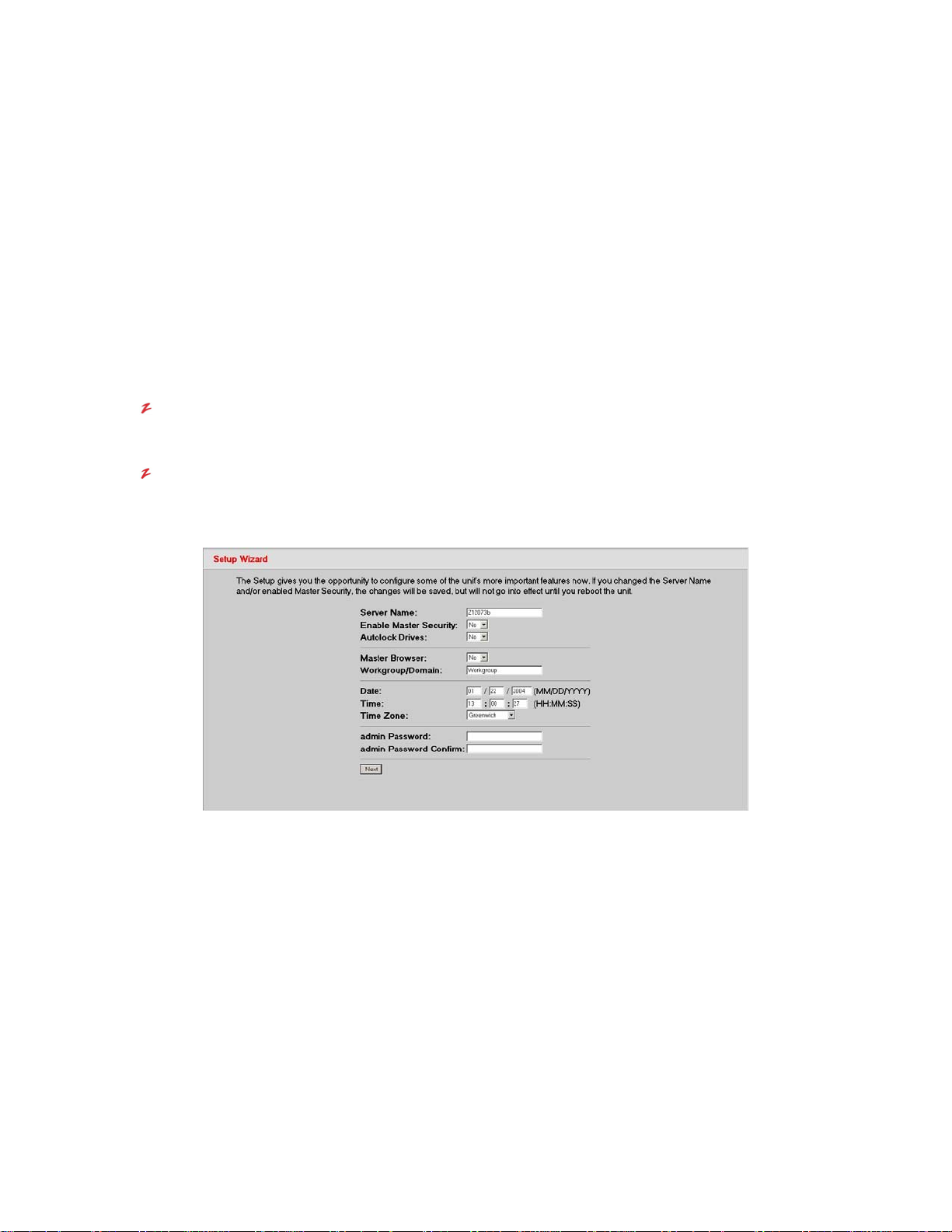
Setup Wizard
The first screen to appear is the Setup Wizard. If you already have a plan i n place for your VR-N100U that
includes how you want to set the options you are seeing here, go ahead and make your changes. This is the only
time you’ll ever see the Setup Wizard, unless you reset your VR-N100U to factory default settings on reboot.
However, if you don’t want to be distracted by having to deal with setting these options at this time, it is not a
problem. All the options you see here can easily be set and changed at any time using the utilities in the
Administration Toolbox.
If you are just not sure, you can pop ahead to the beginning of 3. VR-N100U Overview. It describes each of the
options in the Setup Wizard and the impact each setting will have on the system.
1. Regardless of what you eventually decide to do here, when yo u have finished doing it, click on the Next
button.
2. You will be presented with the Networks Information Screen and will have t hree availa ble settings options to
choose from, View Network Settings, Change the Static IP Setting, or View/Change DHCP Settings.
Page 19 of 98 All Items Are Subject To Change Without Notice Feb. 2004 Rev 1.0
Page 20
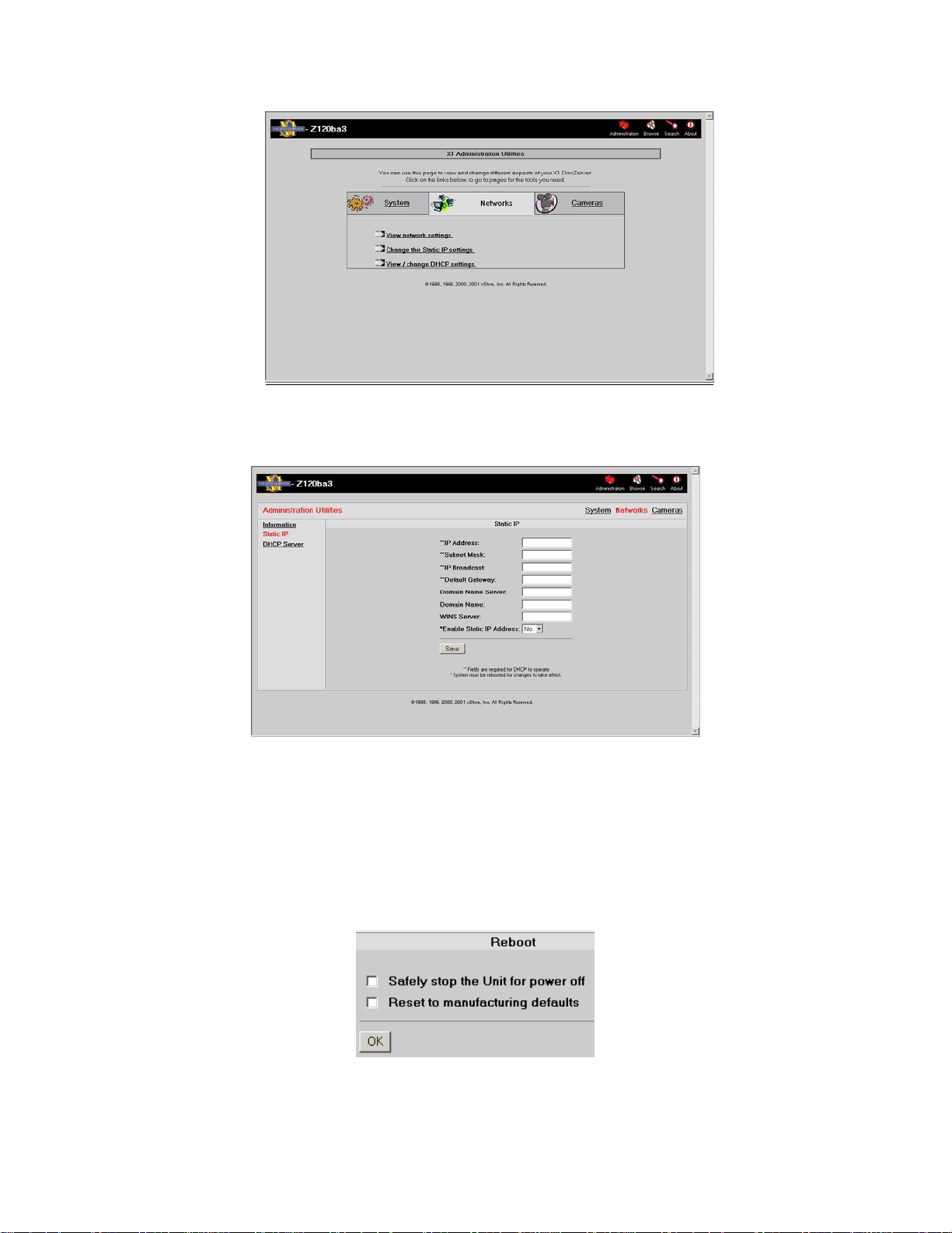
VR-N100U USERS MANUAL
3. Proceed to select the pertinent settings option and fill in t he necessary information. At the very least, you
need to change the IP address under Change the Static IP Address Settings link which will bring you to the
following page.
The Domain Name Server, Domain Name, and WINS Server names are optional. Nevertheless, if you
enter this information, you will be able to address VR-N100U by name. Of course, the WINS (Windows
Internet Naming Service) Server name option is available only in Microsoft Networking environments.
4. Click on the Save button.
2.4.4. Step 3: Rebooting Your VR-N100U
The Reboot screen appears.
1. When you click on the OK button, your VR-N100 U will go throug h an automatic reboot u sing the ne w IP address and
the other information you provided in the form.
2. If you click on Cancel, the information you provided on the Networks Information and Setup Wizard screens is
saved. However, it will not be activated until you reboot the VR-N100U.
Page 20 of 98 All Items Are Subject To Change Without Notice Feb. 2004 Rev 1.0
Page 21
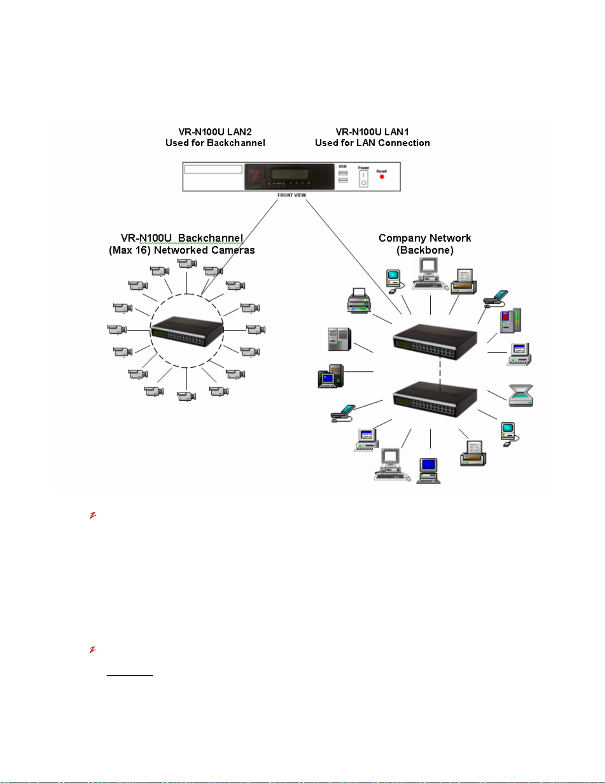
VR-N100U USERS MANUAL
2.4.5. Step 4: Setting Up the Backchannel
Once VR-N100U has been successful installed onto your network, the next step is to configure the “back channel” (also
referred as the camera or video channel) along with the networked cameras.
Backchannel 10/100 Mbit Switch
A dedicated quality Unmanaged Layer 2 24- Port 10/100 Mbit Switch will no w be required to physically attach up
to sixteen (16) VR-N100U supported networked cameras for each VR-N100U. The VR-N100 U will communic ate,
setup, and manage the networked cameras via this backchannel.
1. Utilizing the CAT5/CAT5e net work cable, proceed to co nnect LAN2 of VR-N100U to a one of the ports (e.g.
port 17) of the dedicated Unmanaged Layer 2 24-Port 10/100 Mbit Switch. Both cable and switch were part
of the VR-N100U packaging.
2. Attach the power cord to the 10/100 Mbit switch and proceed to power on the switch.
Networked Cameras
WARNING:
Page 21 of 98 All Items Are Subject To Change Without Notice Feb. 2004 Rev 1.0
BEFORE connecting and powering on the networked cameras, the VR-N100U MUST BE
powered on and online. Failure to do so may cause one or more of the networked cameras
to be configured incorrectly, thus VR-N100U would not be able to recognize or manage the
video device.
Page 22
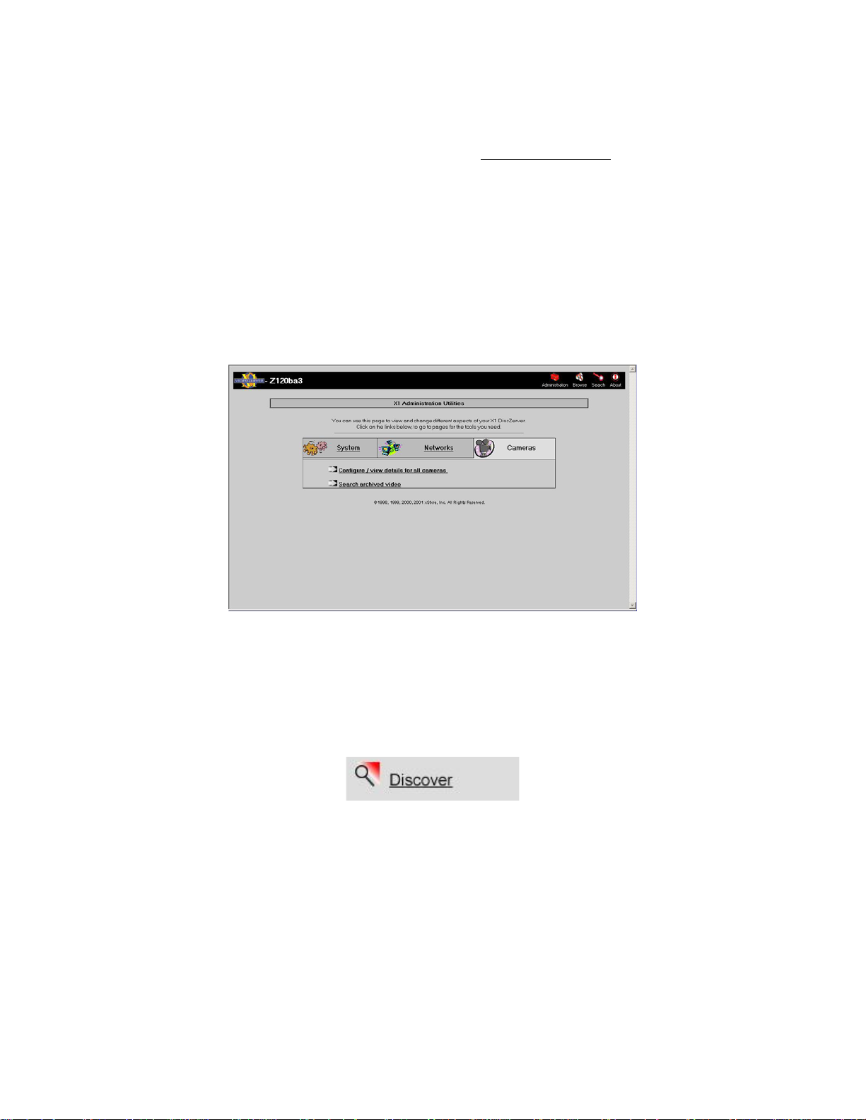
VR-N100U USERS MANUAL
You can now proceed to connect the VR-N100U supported networked cameras to the backchannel switch. For a
list of supported cameras, you can refer to section 5.2 Netw ork IP Cameras for the latest updated information.
The networked cameras can be either native IP-bas ed or traditional analog-based that utilize special analog-todigital converter devices to network enable them. It is highly recommended that we first attach all of the
networked cameras to the VR-N100U backchannel locally (phys ically near VR-N100U) in order to ensure that
they are all working properly and are rec ognized by VR-N1 00U prior to in stalling them into their final destination.
This will make the troubleshooting, if needed, a lot easier as you have all of the cameras and VR-N100U
together at one location.
3. Connect each of the networked cameras (up to 16 per VR-N100U) to the dedicated backchannel switch
using CAT5/CAT5e Ethernet cables (e.g. ports 1~16).
4. Connect the proper power supply to each c amera an d proc eed to po wer on each of the n etworked cameras.
Please refer to the camera’s owners manual for detail specifications.
5. Using your web browser, proceed to log into VR-N100U as an administrator and select the Cameras
administration page.
6. Prior to viewing the networked cameras, your workstation will need to have the proper Java Runtime
Executable from Sun Microsystems installed and loaded. VR-N100U should automaticall y prompt you with a
Java installation window if the correct JRE is not discovered on your system. Please procee d to ACCEPT
the installation of Java onto your system. This process will take a few minutes and may require a reboot of
your workstation, but should be a one-time procedure.
7. After Java has been successfully installed, log back into VR-N100U and return to the Camera utilities page.
When you click on the Discover button under Configure/View Details for All Ca meras pag e,
VR-N100U will go through an automatic discovery of each networked camera device it detects on its
backchannel, automatically configure them and include them as valid network cameras for VR-N100U.
Whether it is one or sixteen network cameras, it is a ver y f a st and e as y process. T here is no need to log in t o
each individual networked camera (one at a time) to setup and save its network settings.
8. Now you can click on a ny of the camera view buttons (2, 4, 8 or 16 Cameras) and it should automatically
display the associated number of cameras on the page as well as the live video feed from the camera(s).
Page 22 of 98 All Items Are Subject To Change Without Notice Feb. 2004 Rev 1.0
Page 23
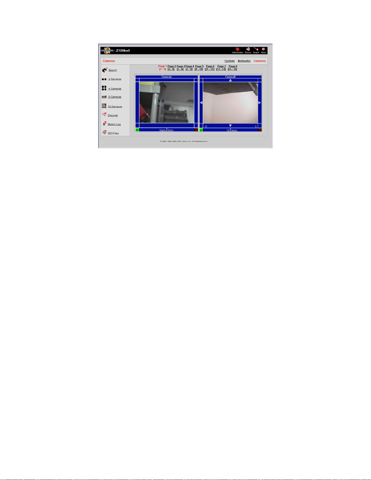
VR-N100U USERS MANUAL
9. If all of the networked cameras are recognized and viewable by VR-N100U, you may power off each
camera, disconnect their network cable, and proceed to install them i nto their permanent assigned locations
within your particular environment.
NOTE: If any of the networked cameras did not get recognized, proceed to section 6. Technical Tips and
Troubleshooting section for assistance.
2.4.6. Where to Go From Here
You are all connected, powered, IP addressed, attached and ready to go. So, now what - where to go from here?
Before you begin exploring the features of the VR-N100U, you may want to plan your NT Domain or Active Directory
integration. Integration into these platforms provides a focused approach t o administering users, groups and the c ameras on a
secure VR-N100U, and, as you learn about the VR-N100U features described in the next chapter, you’ll be able to picture their
implementation under the platform integration you have planned.
You can begin your exploration of VR-N 100U in the next chapter, which presents an overvie w of VR-N100U features. You’ll
find that VR-N100U offers a lot more control and functionality other than managing cameras on the network.
Page 23 of 98 All Items Are Subject To Change Without Notice Feb. 2004 Rev 1.0
Page 24

VR-N100U USERS MANUAL
3. VR-N100U OVERVIEW
This chapter describes the functionality and features of VR-N100U and how they are managed using the VR-N100U web
browser interface.
What makes managing IP cameras on a network possible? VR-N100U supports access to the cameras from a variety of
network platforms. If you are on a Mac, or a Unix system, if you are running Windows (98, NT, 2000, 2003, XP), it doesn’t
matter. You and the other networked users with associated rights will have secure, fast, and direct access to the same
camera(s) on the VR-N100U. And, from a user’s standpoint, that is all that matters. The fact that VR-N100U provides
automatic camera recognition and configuration, or that vi deo can be made available both from live camera fee ds connected
to any VR-N100U and previewed from the captured video stored on the local RAID of the VR-N100U is of little consequence to
the average user on the network. But, it is very important to the VR-N100U administrator, as is the ability to configure the
system and camera security, and manage users, groups and the storage.
There are four levels of security available in VR-N100U and they can be applied to each individual camera to offer the
maximum flexibility and security. The VR-N100U administrators and users with admin/Manager rights can setup and custom
configure each camera to their specific needs. Users with operator rights can control and vie w the cameras which they have
permission on. Users with viewer rights can only view cameras which they have been assigned permission to. Finally,
cameras for which users have no permission will automatically not be displayed to eliminate any confusion and reduce the
number of support issues for the administrators.
Management of the VR-N100U system and network connections is h andled through the VR-N100U web browser interface.
Also, VDRView offers a Web Connection tab so that will launch the web browser within the application window. This chapter
describes the features of VR-N100U and how they are ma nag ed using the web browser interface. Following chapters descri be
the VR-N100U management features of the standalone Enterprise Windows-based application, VDRView.
One of the hallmarks of the VR-N100U is its flexibility. It offers a number of ways for you to make c ameras available to key
networked users. The versatility and flexibility of VR-N10 0U is demonstrated in the interface as well. VR-N100U detects your
hardware configuration and organizes the interface acc ordingly. For example, if VR-N100U detects the presence of one or
more hard drives, the components of the interface that allow you to create RAID sets are displayed. If no hard drives are
detected, these features are eliminated from the interface. If a VR-N100U has only one camera attached, then only one
camera window will be active.
This chapter, VR-N100U Overview, describes the VR-N100U features and the management tasks of those features the
interface was designed to perform. You should read this chapter in its entirety to develop an ov erall understanding of VRN100U and all the things it is capable of doing. The sections that include The Administration Utility in the title provide a feature-
by-feature, detailed description of each of the Administration Utilities used to execute each of the management tasks.
The utilities in the Administration Toolbox are divided into three groups: the System Utilities, Networks Utilities, and, of
course, Camera Utilities. The System Utilities contain t he tools you will use to manage VR-N100U, its storage devices, and
users and groups. The Networks Utilities fall more into the category of set it and forg et it. The options in this group include
setting server protocols and IP addresses. The Camera Utilities cover all aspects regarding setting and access management
for each individual networked camera.
Page 24 of 98 All Items Are Subject To Change Without Notice Feb. 2004 Rev 1.0
Page 25

VR-N100U USERS MANUAL
3.1. Getting to the VR-N100U Web Browser Interface
You can use any web browser, such as those from Microso ft IE or Netscape, to acc ess the VR-N1 00U web bro wser interface.
Use one of the following URLs in the address/location field of your web browser to bring up the VR-N100U interface:
The VR-N100UName
This method requires the Windows environment. Your workstation and the VR-N100U must be on the same
subnet. You will use the VR-N100UName as the URL, which can be the default name printed o n a label on the
enclosure, or a name assigned to the VR-N100U using the Setup Wizard or the General System Utility. The
default name takes the form ZXXXXXX. Examples include: http://Z173AF0/, or http://VDR100U/.
The DNS (Domain Name System) Name
Before you can use this method, the DNS name must be added to your DNS server. An example is
http://VIDEO_ZERVER.VIDEO.COM.
The IP Address
An example is http://192.168.20.95.
It is assumed that the first person who accesses the VR-N100U interface will be you, the VR-N100U Installer and
Administrator. When the web browser connects with the VR-N100U, a password prompt dialog such as the Internet Explorer
dialog shown here will display. The default us er nam e and pass word are admin and admin. After you provide the admin/admin
user name and password and click on the OK button, the VR-N100U Setup Wizard displays.
3.2. The VR-N100U Setup Wizard
The Setup Wizard was designed to give you the opportunity to establish some preliminary settings for your VR-N100U
configuration. It appears only this one time, the first time you log in to the VR-N100U web browser interface. You won’t see this
screen again unless you reboot the VR-N100U to the default factory settings.
For those of you who have a specific plan for your VR-N100U, the appearance of the S etup Wizard at this time allows you to
move forward with your plan. For those of you who want to explore the VR-N100U i nterface before you make any ch anges to
the default settings, be assured that each of the options offered in the Setup Wizard is available in the utilities pages such as
the main Administration Utilities page and can be set any time at your convenience.
Page 25 of 98 All Items Are Subject To Change Without Notice Feb. 2004 Rev 1.0
Page 26
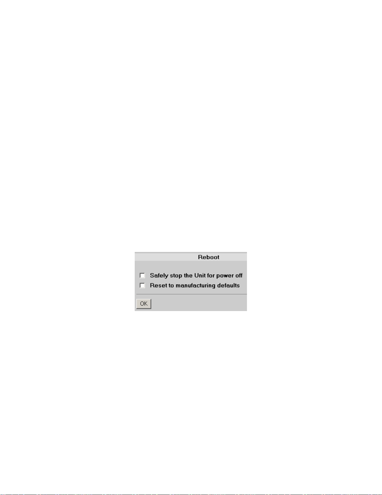
VR-N100U USERS MANUAL
3.2.1. Server Name
Let’s have a look at the VR-N100U Setup Wizard. The first field displays the default name of the VR-N100U. Since this is the
name by which the VR-N100U will be recognized on the network, you may want to change it to something more meaningful,
even if it is just VR-N100U, SecuritySystem or CameraServer. The name you choose can have up to 24 alphanumeric
characters and the dash. (The dash cannot be the first or last character of the name)
3.2.2. admin Password & admin Password Confirm
The next option is a very important one. The default admin Password is admin. You j ust used it in the password prompt to
gain access to this screen. In the future, you will be prompted for an admin password every time you want to get into the
Administration Toolbox. It is strongly recommended you change the admin Password at this time to ensure that other users
will not be able to get into the Toolbox, unless you specifically give them admin/Manager rights. (Those users assigned
admin/Manager rights will use their own user names and passwords to gain access to the Toolbox) You can change the
admin Password any time you want to, using the General Settings section of the System Utility.
3.2.3. Date, Time & Time Zone
You have the opportunity to set the current Date and Time on the VR-N100U system clock, using the format indicated. You
can also indicate the time zone you are in by choosing the name of your city, or a city that is in your time zone, from the dropdown list. The Date and Time settings can be set or changed at a later time using the System Utility.
When you have finished setting options and making ch anges, click on the Next button. Your changes, if you made any, will be
saved.
The next screen, the Reboot screen, offers two options. If you click on the Yes button, the VR-N100U will reboot and the
changes you made will go into effect. If you click on the Cancel button, you will go directly into the first page of the
Administration Toolbox, the Devices page. The changes you made have been saved, but will not go into effect until you reboot
the VR-N100U. If you didn’t make any changes to the Setup Wizard, there’s no need to reboot!
Finally, you are in. Normally, when you log in to the V R-N100U interface, it will open at the Cameras Administration Utility
page. But for this first time only, the Devices page displays. If you are testing your installation, this is the page you need to see
to verify that your connected devices are properly installed. So, let’s start our discuss ion a bout manag ing your VR-N100U here
on the Devices page in the Administration System Utilities page.
Page 26 of 98 All Items Are Subject To Change Without Notice Feb. 2004 Rev 1.0
Page 27
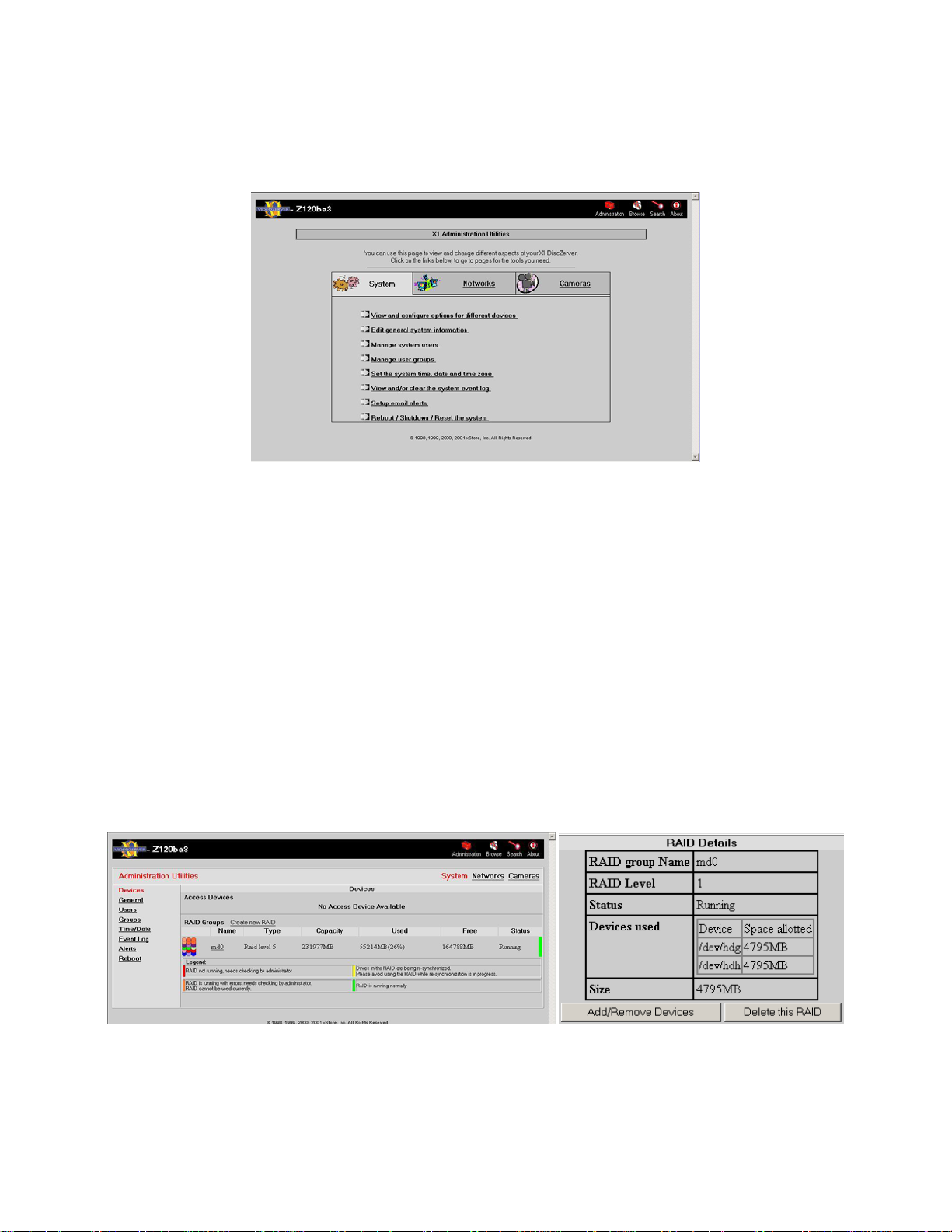
VR-N100U USERS MANUAL
3.3. The Administration “System” Utilities
Using your standard web browser or via the VDRView Web Connect, the VR-N10 0U administrator can easily and securely
navigate to the various System Utilities Pages.
3.3.1. Managing Your Devices
By selecting the View and configure options for different devices link, it will bring you to the Devices page that provides an
overview of all of the devices attached to your VR-N100U. One of the immedi ate management ben efits of the Devices p age is
that you can quickly see the current configuration and status of eac h attached device. If you don’t see a device d isplayed on
this page, you know that your VR-N100U has not detected its presence. You can also click on a specific device to view
additional details about the device.
ATAPI and SCSI based CD and DVD drives are normally classified b y VR-N100U as Access Devices. For VR-N100U, these
types of Access Devices are currently not supported and not installed on the security appliance.
Storage devices are hard drives. Hard drives on a VR-N100U have one primary function which is to store the captured video
from the networked IP cameras. If VR-N100U does not detect any hard drive on the VR-N100U, the security appliance will still
be fully functional in managing all networked security cameras, however, no video will be captured and stored on the appliance
until the Storage Devices are correctly configured.
VR-N100U allows the administrator to configure and Create New RAID Groups as RAID-1 or RAID-5. On this page,
information such as name, type and total/used/availa ble capacities are available, plus an easy-to-understand color sc hema
Legend to determine the current status of the RAID Group. Detail information about the RAID can be made available by
clicking on the name of the RAID set.
Page 27 of 98 All Items Are Subject To Change Without Notice Feb. 2004 Rev 1.0
Page 28
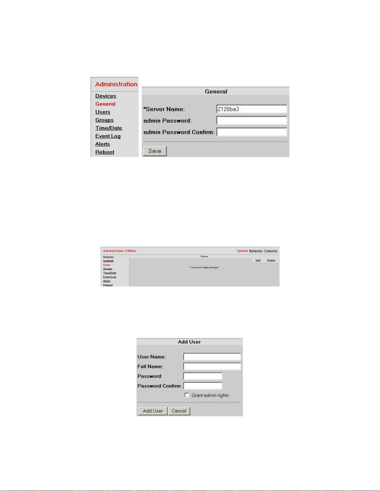
VR-N100U USERS MANUAL
3.3.2. General Settings
The General page allows the VR-N100U administrator to easily change the security appliance’s Server Name as well as
update the admin Password settings.
The Server Name has a maximum length is 24 alphanumeric char acters, where the dash/minus sign (-) is not allowed as the
first or last character. For the admin Password, there is a limit of 15 alphanumeric characters with both the comma (,) and
blank space ( ) are unsupported characters. When you ch ange any of these setting, generally it will require VR-N100U to
reboot to activate the new changes.
3.3.3. Managing Users and Groups
In order to set up the secured system, you have to create a VR-N100U Users List. You will includ e in this list the name of
every user who needs to have access to at least one network IP camera on any of the available VR-N100U security
appliances. The Users List is managed in the Users System Utility and can support thousands of entries. T his utility allows
you to add and delete users, and edit user profiles.
By clicking on the Add button, the Ad d Us er page will appear prompting you to enter the User Name, Full Name and VRN100U Password. The User Name can have up to 24 alphanumeric characters and the underscore with the following
characters classified as unsupported (\ / : ; , * ?). The Full Name can have up to 49 alph anumeric char acters with the follo wing
classified as unsupported (? * \ " \ / < > ` ' , : &). The Password can have up to 15 alphanumeric characters, excluding the
comma (,) and blank space ( ). If you want the user you are adding to have administrative rights to V R-N100U, click on the
Grant admin rights checkbox.
By clicking on the Delete button, the Delete User page will appear prompting you to select the checkbox(es) next to the
name(s) of the user(s) you want to delete. Click on the Delete button and a Deleting Us ers confirmation page app ears, listing
your selections. If you are satisfied with the selection(s), click on th e Delete button, or else select Cancel button to return to
the Delete Users page without deleting the selected users. Change yo ur selections, or click on the Cancel button to return to
the Users page.
Page 28 of 98 All Items Are Subject To Change Without Notice Feb. 2004 Rev 1.0
Page 29
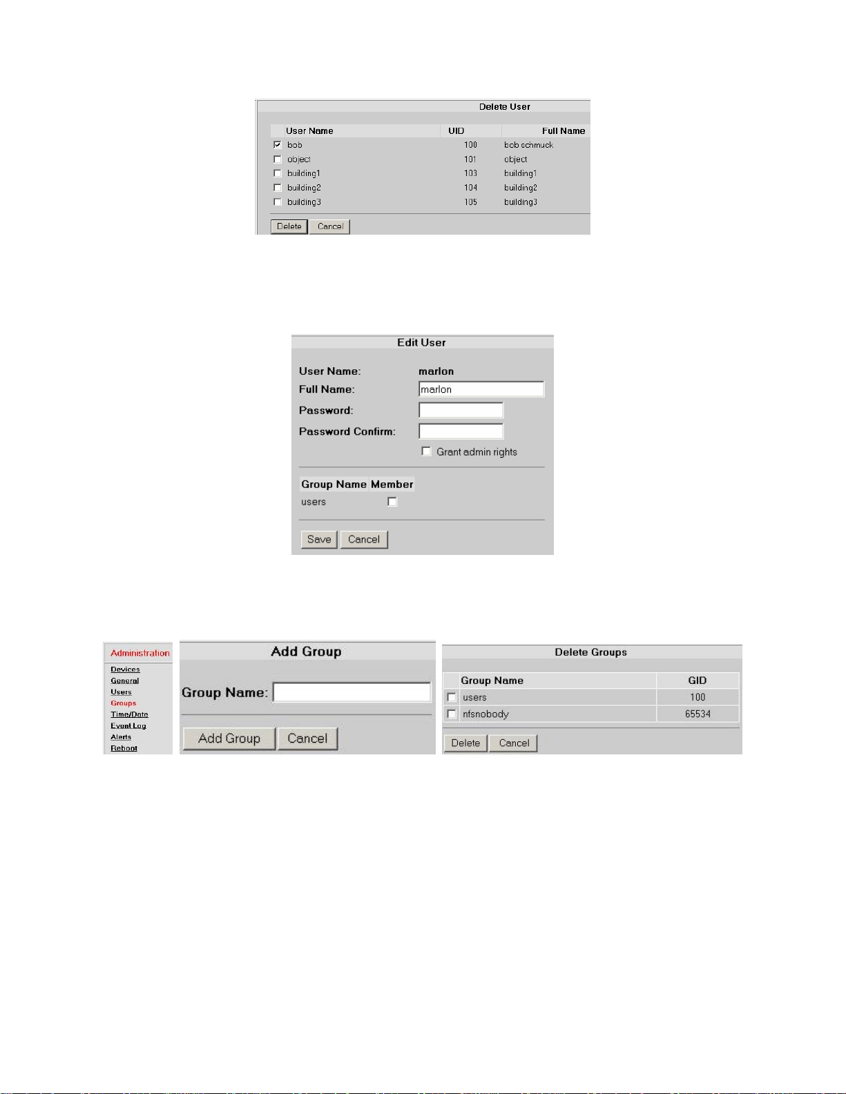
VR-N100U USERS MANUAL
If you want to change a user’s Full Name, VR-N100U Password, or admin rights, or assign the user to a group or rem ove the
name from a group, click on the user’s name. Make your editin g changes in the appropri ate field(s). Change the admin rights
setting by clicking on the checkbox. A check in the box next to the name of a group i ndicates that th e user is a member of that
group. Make the necessary assignments and changes. Y ou can proceed to click on the Save button to save the edits or click
the Cancel button to return to the Users page without making any changes.
The users in the Users List can be organized into groups. You can hav e hundreds of groups in your VR-N100U Grou ps List.
The Group List is managed in the Groups System Utility. You will use this utilit y to add and delete groups, and edit group
profiles. You can add user names to groups, or remove user names from groups in either the user profiles or the group
profiles. The Group Name can have up to 24 alphanumeric characters, excluding the follo wing (\ / : , * ?).
Organizing users into groups makes camera management easier to set up and manag e. After you have defined the user base
and established group memberships, you can assign groups and individual user’s access rights to VR-N100U on a camera-bycamera basis, using the Details page for the individual camera under the section 3.5.7 Setup Camera-Level Secur ity.
Users logging in to a VR-N100U System will be prompted t o provid e a us er name and password befor e they are g iven access
to the Cameras utility page when they access cameras via the web browser interfac e. After the user has been authenticated,
the Cameras utilit y page is displayed. Onl y the cameras to which the l ogged in user has bee n given access rights will display
on any of the X Cameras page (where X is 2, 4, 8 or 16 simultaneous camera vie ws on the screen).
Page 29 of 98 All Items Are Subject To Change Without Notice Feb. 2004 Rev 1.0
Page 30
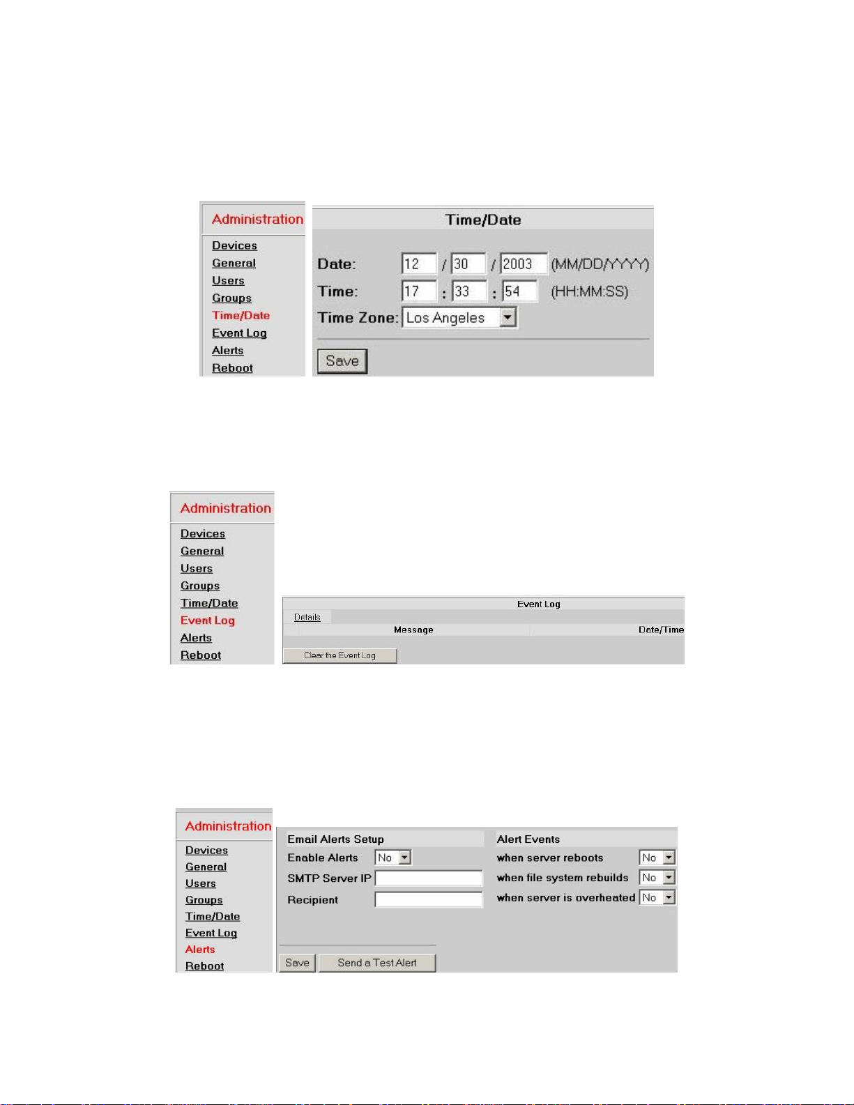
VR-N100U USERS MANUAL
3.3.4. Time Keeper
The Time/Date page allows the administrator to easily change or setup the current Date, T ime and speci fy the local time zone
for the VR-N100U. It is very important to maintain the accurate local settings as it will directly affect the accurate ability to
search on any of the captured video. VR-N100U also us es t he date an d ti me settings when it is logging VR-N100U activities in
the Event/Motion Logs and tracking the creation date and time of ISO Image File creations.
3.3.5. Server Event Log
The Event Log displays a listing of all VR-N100U activities. T he main page displays primary server ev ents. Click on Details
button to view all server events. If you are having an unexplained pr oblem with your VR-N100U, be sure to check the Event
Log to see if it has logged an indication or explanation of the problem.
NOTE: It is recommended that the VR-N100U a dministrator keeps an eye on the Event Log and clicks on the Clear the
Event Log to delete the log file as it may directly affect the performance if it becomes too large.
3.3.6. Server Event Notification
You can be assured of being notified about specific VR-N100U events when you enable the Alerts System Utility. If VRN100U reboots, for example, you and other designated recipients will be notified of the event via email.
This feature can be toggled on and off using the Enable Alerts field. You can configure the Alerts page and turn it off until you
are ready to use it.
Page 30 of 98 All Items Are Subject To Change Without Notice Feb. 2004 Rev 1.0
Page 31

VR-N100U USERS MANUAL
1. Select the Yes option from the drop-down Enable Alerts list when you are ready to activate Alerts.
2. Enter the IP address of your organization’s SMTP Server in the next field.
3. In the Recipient field, enter the e-mail address of each person you want to be notified when one of the selected
server events listed in the Alerts Events section occurs. Each email address should be delimited by a comma, a
semicolon, or a space.
You can now choose the type of event which you want to be notified about.
4. Select the Yes option for each alert notification you want the recipient(s) to receive. They include server reboots, file
system rebuilds, and overheating of the system.
5. Click on the Save button to save your choices. Click on the Send a Test Alert button to verify that the Email Alerts
were properly configured.
3.3.7. Server Reboot
The last available option under the System Utilities Page is the server Reboot System Utility. This should b e used whenever
possible to reboot VR-N100U. The VR-N100U offers three options as part of a graceful reboot, Safely stop the Unit for
Power off, Reset to manufacturing defaults, and a basic Reboot.
When you plan on powering off the VR-N100U, you m ust select the S afely stop the Unit for power off option and then press
OK. This will allow VR-N100U to power down using a managed, controlled process designed to protect the VR-N100U
equipment prior to power off. This may take a few minutes. You can check the front LCD and wait until “System Halted Power
Off” is displayed or if the Status LED is solid RED before pressing and holding the toggle power switch in the off position.
If you need to reset the VR-N100U back to its original manufacturers defa ult settings, then select this option and press OK.
This will temporarily reset the VR-N100U back to its default setting (e.g. 10.10.10.10 IP address and admin as the
administrator name/password) after completing the reboot.
Finally, if you need to reboot the VR-N100U for any reason, do so by pressing the OK button.
WARNING
: NEVER unplug the power from the VR-N100U, press the front recessed Reset Button, or force a power
off by holding down the power switch unless instructed by a VR-N100U authorized support personnel.
Doing so will cause a “Dirty Shutdown” which could result in damage as well as require the system to
spend a large amount of time to check and resynchronize all setting and devices before coming back
online and ready.
Page 31 of 98 All Items Are Subject To Change Without Notice Feb. 2004 Rev 1.0
Page 32

VR-N100U USERS MANUAL
3.4. The Administration “Networks” Utilities
Proceed to select the Administration icon on the VR-N100U Toolbar to get back to the main Administration Utilities page.
From there, select the Networks Utility Page link to navigate to the following pages.
3.4.1. Network Information
By selecting the View network settings link, it will bring yo u to the Information page that provides an overview of all of the
network settings for your VR-N100U. One of the immediate management benefits of the Information page is that from a
single screen, the administrator is able to determine the current networking setting of the VR-N100U.
This page displays the IP Address, Subnet Mask, IP Broadcast, Default Gate way, DNS, Domain Name, WINS Server, AFP
and Ethernet Address information of the VR-N100U as well as how some of the settings were obtained. Details regarding any
of these network parameters can be found in the 7. Glossary of Terms section of the manual.
3.4.2. Static IP Setup
Administrators can easily setup static IP addresses for each VR-N100U in the event that there is no DHCP server being
utilized on the network. By selecting the Static IP link, the window will display a form with seven fields. Information regarding
IP Address, Subnet Mask, IP Broadcast and Default Gateway must be filled in along with selecting Yes for Enable Static IP
Address. Proceed to click the Save button, and then a reboot screen will appear. You must select the Yes button so that VR-
N100U can go through an automatic reboot using the ne w IP address and the other information you provided i n the form. If
you click on Cancel, the information you provided will still be save d, however, it will not be activated u ntil you reboot the VRN100U.
Page 32 of 98 All Items Are Subject To Change Without Notice Feb. 2004 Rev 1.0
Page 33

VR-N100U USERS MANUAL
3.4.3. DHCP Server Option
Your VR-N100U can also be configured as a DHCP Serv er to automatically distribute IP addresses to Windows client s that
request them via LAN2. You have to assign your VR-N100U a static IP address, but once you do, your VR-N100U can
function as a DHCP Server. You will use the DHCP Server Net works Utility to set up and monitor auto-IP addressin g by your
VR-N100U.
The DHCP Server option allows you to indicate whether or not you want to establish the VR-N100U as a DHCP serv er. The
default setting is No. Look at the Current DHCP Status section near the bottom of this utility p age to determine whether the
VR-N100U is currently configured to be a DHCP server. If it is, you probably changed this setting initially in th e Networks
Information screen when you manually configured VR-N100U during i nstallation. If you c hoose Yes now, your VR-N100U will
dynamically assign IP addresses to network devices co nfigured to receive them. The VR -N100U must be properly configur ed
via the Static IP utility before it can behave as a DHCP server. If your VR-N100U has made any assignments, they will be
shown below the heading Assigned Nodes.
If you want your VR-N100U to act as a DHCP server and you set the DHCP Server option to Yes, then
1. Enter the starting number of the range of IP addresses you want to give out in the DHCP Range Start field.
2. Enter the upper threshold of the range of IP address numbers you want to give out in the DHCP Range Stop field.
The IP Boot State option indicates the original boot state of VR-N100U (e.g. how it received its original IP address).
3. Click on the Save button to save your DHCP server configuration settings.
When the DHCP server begins giving out IP addresses, they will be reported in the last section at the bottom of the page.
4. Reboot the VR-N100U to put the changes into effect.
Page 33 of 98 All Items Are Subject To Change Without Notice Feb. 2004 Rev 1.0
Page 34

VR-N100U USERS MANUAL
3.5. The Administration “Cameras” Utilities
Proceed to select the Administration icon on the VR-N100U Toolbar to get back to the main Administration Utilities page.
From there, select the Cameras Utility Pages link to navigate to the following pages.
By selecting the Configure/View Details For All Cameras link, it will bring you to the Cameras utility page that provides the
ability to conduct a search of the captured video, setup the current camera display l ayout, ability to auto-discover cameras,
view any motion logs and ISO image files that may exist. By default, the page will display one of the available camera views.
3.5.1. Search
By selecting the Search link, it will bring you to the Search Recorded Footage page that provides an very easy and straight
forward way to do a random access search for any archived video from any camera managed by VR-N100U. VR-N100U will
quickly determine if the video segment you are requesting is available on the local RAID once you specify the Camera,
recording date and the time period (From and To), and click on the Search button.
Page 34 of 98 All Items Are Subject To Change Without Notice Feb. 2004 Rev 1.0
Page 35

VR-N100U USERS MANUAL
If it was unavailable, then “Searching…” would be replaced with “No Recordin g Found for Specified Interval” message. If the
video segment is found, then the first frame of the motion video would be automatically displayed in that window. VR-N100U
also provides the ability to control the basic playback method (slow down, speed up, pause/play, play backwards or forwards).
If you decide that you want or need a copy of this video clip, VR-N100U offers a very powerful and easy option.
1. Click on the Export to ISO Image link at the bottom of the window.
When selecting this option, the video segment will be aut omatically premastered into an ISO-9660 compliant format by
VR-N100U.
2. When completed creating the ISO image, VR-N100U will open a new windo w with a “Click here to download ISO”
link will appear. Click on this link so that you will be automaticall y prompte d with the File Download window to specify
the location where you want to save the image.
3. Once the image file has been copied to your local workstation, you can use any CD/DVD recording software (e.g.
Roxio Easy CD/DVD Creator) and a recordable drive to record the premastered video disc image onto a blank disc.
Page 35 of 98 All Items Are Subject To Change Without Notice Feb. 2004 Rev 1.0
Page 36

VR-N100U USERS MANUAL
3.5.2. Camera Views (2, 4, 8, 16)
Each user may have their own preference in regards the simultaneous vie wing of network cameras. Therefore, VR-N100U
allows the user to select from a 2 camera, 4 camera, 8 camera, or maximum 16 cameras to be displayed. If the maximum
number is not selected, you can switch bet ween p ages to s ee th e other ca meras. Be lo w are a coup le of screen shot examples
for the camera views (2 Cameras and 4 Cameras).
The frame surrounding each camera window may slightly vary bec ause of the camera functionality (Fixed, PTZ, Motion, or
combo).
Camera Name
All cameras will display the associated nam e at the top. The default names will be assi gned from CameraA to
CameraP which represent discovered cameras 1 to 16.
Camera Recording Status
All cameras will have the current status on the lower-left corner (Continuous Recording off/on, Motion Control
off/on-if supported). By clicking this button, you can toggle between the various support ed recording m odes. The
default setting will be Off on all cameras as the VR-N100U administrator will setup each camera accordingly.
The page will change and prompt you to allow you to reconfirm the change in recording status.
Auto Playback
All cameras will have the Aut o Playb ack button located on the lower-right corner. By clicking this button, the
playback window will open up and automatically displa y the last minute of recorded video for that camera (if
available).
Page 36 of 98 All Items Are Subject To Change Without Notice Feb. 2004 Rev 1.0
Page 37

VR-N100U USERS MANUAL
Details
All cameras will display the Details link at the bottom center. By clicking on this link, it will take you to the
Camera Configure page where various setting can be changed on eac h camera. A n e w windo w will ap pear (see
examples below).
On the left side of the screen, a 4x4 matrix is available that allows the administrator to easil y switch bet ween any
of the 16 cameras from within this same window. This is standard when viewing details for all camera types.
In the center of the screen, a live video feed is presented with the ab ility to access detail settings for t he current
camera. There will be an Image/View Configuration link for all cameras, plus a PTZ link for pan-tilt-zoom
supported cameras. When clicking on Image/View Configuration, another window appears offering detail control
over the camera. Options and settings will vary bet ween different makes and models of cameras (see example
below). When clicking on PTZ, it will open up the same PTZ control window that was mentioned earlier.
On the right side of the Camera Configure page, you are able to vie w/change the name of the camera (maximum
of 50 alphanumeric characters), see the assigned IP/MAC addresses and type of camera (make/model), as well
as change some basic parameters such as the duration for stori ng the video (1, 2, 3, 4, 5, 7, 10, 14, 15, 20, 21,
25, 28, 30, 45, 60, 75, 90 days) and setting the maximum fps (1 to 30 frames per second). There is also a
Manage Users for this Camera link to allow the administrators to setup the user level security from within
another window (see 3.5.7 Setup Camera-Level Security for details). These are standard items when viewing
details for all camera types. If the camera supports motion detection, then a Configure Motion Detection link
will be available on the lower right corner (see 3.5.6 Setup Motion Detection for details).
PTZ or Magnify
Depending on the camera’s functionality (PTZ or other), either the PTZ link or Magnify link will be displaye d at
the bottom center. By clicking on this link, it will open a new windo w that will offer additional setting changes for
that camera.
Page 37 of 98 All Items Are Subject To Change Without Notice Feb. 2004 Rev 1.0
When you click on the PTZ link, a new window will open up that displays contro l options for that particular PTZ
camera. In addition to the various control options presented under the m ulti-camera view window, further detail
settings pertaining to that particular camera are available. They may inc lude the Resolution Size, specifying the
Page 38

VR-N100U USERS MANUAL
use of a Preset setting programmed on the camera, creating/editing presets, and ability set the Auto-pan. These
parameters and options may slightly differ based on the make and model of the PTZ camera.
When you click on the Magnify link for the fixed camera, a new window displaying resolution options will open
up. These parameters and options may slightly differ based on the make and model of the fixed camer a.
Pan/Tilt Arrows
PTZ supported cameras will have these arrows on each side of the window. By clicking on thes e ↑ or ↓ or ← or
→ arrows, the camera will either tilt up/down or pan left/right in the direction selected.
Zoom In/Out
PTZ supported cameras will have these buttons on the lo wer left and right corners. By cli cking on these Z+ or Z-
buttons, the camera will either zoom in or out.
Page 38 of 98 All Items Are Subject To Change Without Notice Feb. 2004 Rev 1.0
Page 39

VR-N100U USERS MANUAL
Configure
Cameras that were not recognized by VR-N100U or did not exist will only display “Not Configured – please click
‘Configure’ below” on the center of the window. By clicking on the Configure link, it will take to the Configure
page where you can try to manually configure that p articular camera if it physically exists on the backchannel.
You must specify the camera name, internal IP address, selecting th e camera type from the pull-down list and
finally specifying the requested duration of video storage for this particular camera. VR-N100U will then attempt
to add that camera to itself after you click on the Save button.
Camera Problems
If any camera that was discovered and supported by VR-N100U suddenly goes offline, “Camera Not
Responding” message will appear in the window. Check to make sure that the camera is still powered and tha t
the network cable from the camera to the backchannel VR-N100U switch is still attached and not damaged.
Auto Centering for PTZ
At any time, if you click on any particular location on a PTZ camera view, VR-N100U will automatically position
the PTZ camera so that it shows the location as the center of the view. However, if the location is beyond the
PTZ camera’s physical range, then it will attempt to get it as close to the center as physically possible.
NOTE: For further detail information pertaining to the various parameters, please go to section 5.2 Network IP Camer as for
more information.
3.5.3. Discover
One of the most difficult tasks customers are faced with when utilizing n etwork IP cameras is the ability to confi gure them. All
cameras come standard with their own manufacturer’s default settings. Also, the web interface and/or s oftware utility p rovided
with the cameras are very unique between manufacturer as well as between different models from the same camera
manufacturer. Setting up a handful of network IP cameras is not very difficult, but when you have to setup hundreds or
thousands of cameras and they are of different makes and models, then this task becomes very difficult. Normally, one
camera at a time must be configured (connect to a workstation or LA N, locate the camera, log into the camera, setup the
parameters such as the IP address and login information for the camera, save and reboot to verify that the camera is setup
and functioning correctly). So the task is done in serial manner. By the time you reach yo ur n
crazy” over this tedious but mandatory process.
Now you can throw out all of those concerns and issues as VR-N10 0U automatically takes care of them for you. Once VRN100U is online, you merely attach and power on the network IP cameras to the backchannel, and then select the Discover
button of VR-N100U.
th
camera, you will have gone “stir
VR-N100U will automatically detect and integrate the c ameras and within a few seconds your securit y appliance will be fully
operational with network security cameras online. T he cameras should begin providin g live feeds through the various camer a
view windows. You can proceed to make any necessary setting changes to each individual camer a and setup the cameralevel security assignments. It just does not get any better than this and VR-N100U presents a very uniform interface used
across-the-board for all camera makes and models with minimal variations.
Page 39 of 98 All Items Are Subject To Change Without Notice Feb. 2004 Rev 1.0
Page 40

VR-N100U USERS MANUAL
3.5.4. Motion Log
Network IP cameras are becoming more advanced, as some have incorporated motion detection support within the device.
The advantage of motion detection is that it can allow you to better optimize the storage as the VR-N100U could be setup to
capture video only when motion is detected by the camera in within a specified area. When motion detection is enabled on one
or more supported cameras, VR-N100U will track each event. These log files (video clips) can be easily accesse d by clicking
on the Motion Log button.
The page will display, in chronolo gical order s t arting with the most recent event, the list of each captured motion log alo ng with
the date/time, motion level, threshold, difference, message, and a link to preview the captured video clip. If you click on the
links, the standard VR-N100U playback window will open and displa y the video clip. VR-N100U also provides a legend to
easily identify the level of motion for each entry.
NOTE: To ensure that it does not take up too much overhead, it is recommended that the administrator periodically check the
log and clear (delete) any unnecessary Motion Log files.
3.5.5. ISO Files
When presented with the playback window to view any captured video, the user has the option to create an ISO-9660
compliant premastered image file by clicking the Export an ISO Image link.
With a single click of the mouse, VR-N100U will automatically:
Prepare the video data
Format for compliancy
Create a premastered ISO image file
Log the ISO image
Present a link for downloading the image to your local workstation for recording a CD/DVD disc
Page 40 of 98 All Items Are Subject To Change Without Notice Feb. 2004 Rev 1.0
Page 41

VR-N100U USERS MANUAL
VR-N100U will track each ISO image creation and store these log files (video clips) that can be easily accessed by clicking on
the ISO Files button. This will display the lis t of available files created from searches and provide the camera details, search
start and end times, file size and the link to the ISO file.
NOTE: To ensure that it does not take up too much overhead, it is recommended that the administrator periodically check the
log and clear (delete) any unnecessary ISO Files.
3.5.6. Setup Motion Detection
If any of the network IP cameras support motion detection, then VR-N100U will allow the administrator the ability to uniq uely
setup each camera. When you select the Configure Motion Detection link in the camera Details page, you will be prompted
to log into this configuration page. After successfully logging in, it will bring yo u to the page where you have the ability to
specify detail settings as well as the trigger window for that particular ca mera. A live image of the video feed along with a
motion level window adjacent to available to assist the administrator to determine the various settings for motion detection.
For each supported resolution size that the motion detection supporte d camera offers, you will be able to sp ecify the follo wing
parameters (based on the make/model of camera, some of these parameters may vary). Please check the camera’s users
manual for details regarding the following parameters.
Luminance Threshold
Minimum Object Size
Noise Filter
Reference Image Refresh Interval
Motion Detection Delay
Additional information may be available on the sections 5. 2 Network IP Cameras and 7 Glossary of Terms.
3.5.7. Setup Camera-Level Security
As mentioned earlier, VR-N100U offers administrators the ability to setup camera-level security very easily. T here are actually
four levels of security, but only three levels need to be specified for each camera as administrators always hav e access to all
VR-N100U and their managed cameras. By offering camera-level security, VR-N10 0U administrators have total an d complete
control over all networked security appliance and cameras.
No Access
This is the initial default setting for all VR-N100U users. When a user’s privileges is set to No Access, this
particular camera will not be displayed (hidden) when they attempt to access this VR-N100U securit y appliance.
The user will not be aware that this particular camera exists, thus eliminating any worrie s about someone trying
to hack into the camera or supports calls from users regarding those particular cameras.
Page 41 of 98 All Items Are Subject To Change Without Notice Feb. 2004 Rev 1.0
Page 42

VR-N100U USERS MANUAL
Viewer Level
For administrators who wish to offer the minimum access to any camera, they would assign a user Viewer level
security. This will allow the user to view those cameras which they have privileges on without worrying about the
user changing any of the camera’s parameters.
Operator Level
The highest level of camera security, excluding administrator, that can be assigned to any user is Operator level.
They can not only view the cameras, they have the ability to modify the camera’s p arameters (e.g. pan/tilt/zoom,
resolution, frame rate, etc.).
When you select the Manage Users for This Camera link in the camera Details page, you will be prompted to log into this
configuration page. All of the VR-N100U users will be listed and initially s et to the default No Access security level. By simply
selecting either the Operator or View radio buttons, and then the Save button, the administrator is able to setup the security
levels for that particular camera for all VR-N100U users.
Page 42 of 98 All Items Are Subject To Change Without Notice Feb. 2004 Rev 1.0
Page 43

VR-N100U USERS MANUAL
3.6. VR-N100U’s Toolbar
Most of this chapter has been about the features of VR-N100U that are managed by the utilities of the Administration
Toolbox. The other icons are the Browse icon, the Search icon, and the About icon.
3.6.1. Administration Icon
When clicking on the Administration toolbar icon, it will automatically bring you to the main Administration Utilities page
where you can navigate between the System, Network, and Camera settings pages associated with VR-N100U.
3.6.2. Browse Icon
The Browse icon is a shortcut to pull up the Camera Views page where all of the VR-N100U managed cameras are
displayed.
Page 43 of 98 All Items Are Subject To Change Without Notice Feb. 2004 Rev 1.0
Page 44

VR-N100U USERS MANUAL
3.6.3. Appliances List Icon
The Appliances List will allow you to bring up a list of all VR-N100U security appliances that are discov ered over the n et work,
whether locally on your LAN or remotely over your WAN. This enables you to easily navigate between appl iances as you no
longer need to know what the IP address for all discovered VR-N100U security appliance s.
3.6.4. Search Icon
The Search icon is a shortcut to take you directl y to the Search pag e to locate video from a specific c amera on a spec ific date
during a particular time range.
3.6.5. About Icon
The About icon displays an overview of VR-N100U, version number, and provides links to helpful VR-N100U resource s.
Page 44 of 98 All Items Are Subject To Change Without Notice Feb. 2004 Rev 1.0
Page 45

VR-N100U USERS MANUAL
4. MANAGING VR-N100U WITH VDRVIEW
Overview: This chapter describes the features of the VDRView enterprise video application and how it can be used to manage
thousands of VR-N100U security appliances and cameras.
VDRView is one of those extremely useful tools that makes any administrator, as well as user’s life so much easier. Whether
you’re trying to get your VR-N100U online, reflash the VR-N100U firmware, setup all of the cameras or troubleshoot a
problem, VDRView is probably going to end up being your first line of defense an d favorite administrative tool.
In Chapter Two - Installi ng VR-N100U, you were shown several different ways of man ually acquiring an IP addr ess for a VRN100U that comes up tens (10.10.10.10). VDRView, by far, is the easiest way of manually acquiring an IP address.
We keep working to improve VR-N100U and add ne w features. That means that ever y once in a while, you are going to have
the opportunity to update your VR-N100U’s firmware by reflashi ng the unit. You can choose to update the firmware using an
FTP client to transfer the new image to the VR-N100U (described i n secti on 6 Technical Tips and Troubleshooting), or you can
take the easy way by executing VDRView’s Reflash option.
When you start up VDRView, it discovers all the V R-N100Us on your subnet segment. It displ ays the VR-N100U’s name, its
type (VR-N100U, etc.), its IP Address, by what means the IP address was acquired, the Default N ame of the VR-N100U (the
last six characters of the Ethernet address preceded by a Z), and the location of the VR-N100U (e.g. Same segment).
VDRView is a powerful enterprise application that allows users to view thousands of cameras connect ed to hundreds of VRN100U appliances and to administer all of them from a singl e Windows interface. Its Status Bar also provides you with your
workstation’s IP address and the current date and time information.
4.1. System Requirements
VDRView is a 32-bit Windows-based enterprise application software designed to manage VR-N100U and cameras. Nearly any
computer that meets the requirements to effectively run the Microsoft Windows operating system can utilize VDRView.
However, the more powerful the workstation, the better performance you will encounter as the product will be dealing with
motion video. Therefore, we have outlined both minimum and recommended system requirements. In addition to the standard
hardware specifications, VDRView and VR-N100U require Java to be loaded onto the system to enable viewing the video
streams live from the cameras as well as from the archived video.
4.1.1. Recommended Configuration
The following specifications are outlined for a recommended VDRView workstation. As mentio ned above, the more power the
workstation and faster the connectivity, the better overall video performance you will be able to achieve.
Operating System Windows 2000/XP with latest Service Pack
Processor Intel Pentium IV 3.0GHz, 800MHz FSB, 512Kb Cache (or faster)
Memory 512MB DDR (or higher)
Hard Disk Drive 250GB PATA/133 7200rpm 8MB Cache (or larger/faster)
CD/DVD Drive DVD-ROM Drive (or better)
Video Card AGP 4X 256MB 256-bit (or faster)
Monitor 21” @ 24-bit True Color (or larger)
Browser Microsoft Internet Explorer 6.x with latest Service Pack (or higher)
Java Sun Microsystems JRE 1.4.2_xx (or higher)
Network 100Mbit (or faster)
ISP T1-Broadband (or faster)
Page 45 of 98 All Items Are Subject To Change Without Notice Feb. 2004 Rev 1.0
Page 46

VR-N100U USERS MANUAL
4.1.2. Minimum Configuration
VDRView will also function on a system that meets the minimum specification, however the video may not be as fluid
(smooth), the maximum number of simultaneous video streams may not b e achiev abl e, the p ages ma y take long er to l oad a nd
refresh, but you can always be sure that the video is being captured and accessible from the VR-N100U. The minimum system
requirement will still enable you to manage and control the VR-N100Us and cameras.
Operating System Windows 2000 with latest Service Packs (or higher)
Processor Intel Pentium III (or faster)
Memory 256MB (or higher)
Hard Disk Drive 80GB PATA/100 5400rpm 2MB Cache (or larger)
CD/DVD Drive CD-ROM Drive (or better)
Video Card PCI/AGP 64MB 64-bit (or faster)
Monitor 17” @ 16-bit High Color (or larger)
Browser Microsoft Internet Explorer 6.x with latest Service Pack (or higher)
Java Sun Microsystems JRE 1.4.2_xx (or higher)
Network 10Mbit (or faster)
ISP 56Kb (or faster)
NOTE1: Java can be manually installed onto the VDRView workstation by directly downloading it from the Sun Microsystem’s
web site (http://java.sun.com/products/plugin/
NOTE2: When accessing the VR-N100U directly from the web browser or from VDRView for the first time, you will be
automatically prompted to install Java if it is not already installed on your system. Proceed to accept and follow the
instructions provided from Sun Microsystems.
NOTE3: JRE 1.4.2_01, 1.4.2_02 and 1.4.2_03 have been successf ully tested at the time this manual was wr itten. However,
there is always the possibility that when a new and untested version of Java is releas ed, that it could cause some
unexpected issues.
).
4.2. Installing VDRView
You will find VDRView on the VR-N100U Companion CD. It is intended for the user to install it on yo ur workstation that meets
the above system requirements.
1. Load the VR-N100U Companion CD i n the CD/DVD dr ive on t he workstation. Follo w the inst ructions on the CD lab el.
The CD will autoload. If the CD does not autoload, launch VDRView.exe to manually install and go to step 3.
2. From the Companion CD Main Menu, select the Install VDRView option.
3. When the Setup Wizard appears, follow the instructions on each screen.
You will be prompted to provide a destination location and a Program Folder for the utilities. The default location is th e
Program Files\VDRView folder on your local hard drive. After the files are loaded to the specified destination location, a
prompt appears asking if you want to create a shortcut icon on the desktop for VDRView.
4. Click on the Yes button if you want to create the icon. Click on the No button if you d on’t.
5. The Setup Wizard completes the installation. The final screen offers you the option of restarting your system now, or
at a later time. System-level DLLs are installed with VDRView. They will not be activated until your workstation is
restarted. Make your selection and click on the Finish button. (If you are reinstalling VDRView, you may not be
prompted to reboot.)
You are returned to the Companion CD menu screen. T he View Readme File option co ntains last minute information on
VDRView and the other VR-N100U Companion CD options listed on the Main Menu.
6. If you haven’t already done so, remove the VR-N100U Com panion CD from your CD/DVD drive.
That’s all there is to installing VDRView. You’ll see that using it is just as easy.
Page 46 of 98 All Items Are Subject To Change Without Notice Feb. 2004 Rev 1.0
Page 47

VR-N100U USERS MANUAL
4.3. Discovering VR-N100U Appliances
When you start up VDRView, a splash screen appears. The splash screen stays up until VDRView discovers all the VRN100Us on the same segment of the subnet as your workstation. VDRView uses broadcasts to discover all of the VR-N100Us
on that local subnet.
If you have a large subnet segment, or a lot of VR-N100Us, this process could take up to on e minute or longer. When all VRN100Us have been discovered, the screen will refresh and the newly discovered appliances will be dis played in the list in the
Zerver Center page.
If VR-N100Us exist on other remote subnets, broadcasts will not disc over them automatically. VDRView supports additional
options for discovering these VR-N100Us and are outlined in the following sections (4.6.5 Options – Enable Discovery via
Microsoft Browsing and via Remote Server List). A status bar located at the lo wer right corner may appear to provide you
additional information.
NOTE: It is assumed that you have alre ady completed the setup for your VR-N100U by following the directions provided
under Chapter 2 Installing VR-N100U.
4.4. Logging into VR-N100U
Once your VR-N100U is discovered by VDRView, you can proceed to log into the security a ppliance.
1. Click on the Log In button to open up the login dialog box. It is located on the upper right c orner of VDRVie w’s Zerver
Center page.
2. A login dia log box will open that provides a list of all discovered sec urity appliances. There is an option to Filter the
list to show all logged in, not logged in, and all VR-N1 00Us. Once you select the VR-N 100U(s) you which to lo g into,
proceed to input your user name and password, then sel ect the Authenticate button. T he default settings for all VR-
Page 47 of 98 All Items Are Subject To Change Without Notice Feb. 2004 Rev 1.0
Page 48

VR-N100U USERS MANUAL
N100U security appliances are admin f or both. During this process, the status of the a uthentication will be displa yed
at the bottom of the dialog box.
3. If the login is successful, proceed to click the Done button to exit the dial og box. A successful logi n will automaticall y
update the Login Status and Logged In As fields within the Zerver Center page.
Once you have successfully logged in, proceed to review the rest of this manual so that you underst and how to utilize the
powerful, yet easy to use, VDRView enterprise security appliance utility to securely manage all VR-N100Us and cameras.
Page 48 of 98 All Items Are Subject To Change Without Notice Feb. 2004 Rev 1.0
Page 49

VR-N100U USERS MANUAL
4.5. Definition of Toolbar Icons
VDRView provides many toolbar icons to allow any user to easily navigate within th is Enterprise Uti lit y program for VR- N10 0U.
The most frequently used functions are represented b y icon s on the VDRV ie w toolbar. N ear the top of the VDRVie w page, the
following icons are available:
Zerver Information…
This icon provides basic summary information about VR-N100U such as the nam e, type and IP address.
You can also access this from the Options pull-down menu or via the web browser under the Networks
utility page and is only active when you are in Zer ver Center.
Set Zerver IP Address…
This icon allows an administrator to set the IP address of the VR-N100U. You can also access this from the
Options pull-down menu or via the web browser under the Networks util ity page. Information regarding IP
Address, Subnet Mask, and Default Gateway are the fields that must be filled in and Enable Static IP
Address should be checked.
Administer Zerver…
This icon opens a new web browser window to take you to the main Administration Utilities page on VRN100U after a successful login.
Page 49 of 98 All Items Are Subject To Change Without Notice Feb. 2004 Rev 1.0
Page 50

VR-N100U USERS MANUAL
Reflash Firmware on Zerver…
This icon allows the administrator to update the VR-N100U firmware by reflashing the firmware on the
security appliance. This will open up the VR -N100U List dialog box from which you dra g-and-drop the VRN100U which you wish to reflah onto the main VDRView page. It will then prompt you to log in a nd open up
the Reflash page that will take you to the web bro wser under the Networks utility page. Refer to section
4.7.7 Reflash for more details.
View Large Icons
This icon will display all discovered VR-N10 0U security appliances under Zerver Center as large graphical
icons.
View Small Icons
This icon will display all discovered VR-N100U security appliances under Zerver Center as small graphical
icons.
View List
This icon will display names of all discovered VR-N100U security appliances under Zerver Center.
View Details
This icon will display a detailed list of all discovered VR-N10 0U security appliances under Zerver Center
that includes the VR-N100U name, type, IP address, how the VR-N100U was acquired, default name,
discovery method, and login status.
Edit Remote VR-N100U List…
This icon will open up the Remote Server List window. This will allow the ability to store and activate any
VR-N100U security appliances outside of your current network segment by referencing its IP address or
server name. Once the VR-N100U have been added, you can then proceed to securel y log into them over
SSL. Refer to section 4.6.5 Options – Edit Remote Zerver List for more details.
Communication Settings…
VDRView offers the ability to determine the remote VDR Discover Mode and Communication Method. They
can be setup as non-encrypted or encrypted based on how the VR-N100U was originally setup by the
administrator. Refer to section 4.6.5 Options – Communication Setting for more details.
Page 50 of 98 All Items Are Subject To Change Without Notice Feb. 2004 Rev 1.0
Page 51

VR-N100U USERS MANUAL
New View
VDRView offers the ability to function as an unlimited “virtual” Multiplexer for all of the cameras. Within the
Monitor Cameras page, you have the ability to create your own customized views using the provided
templates. When selecting this icon, you will be prompted with a new window where you simply specify a
name, number of cameras (1, 2, 4, 5, 6, 9 or 16) to be displayed, cam era layout, and provide an optional
description. Once this information is provided, click on the OK button and your new customized vie w will be
displayed. To add the cameras to your ne w vie w, simply click on the Load Camera List icon to open the list
of available VR-N100U and the associated cameras. By me rely draggin g-and-droppin g cameras onto an y of
the camera windows, VDRView will automatically create links to provide the live video feed from those
cameras onto your view. Cameras can be from the same and/or different VR-N100U.
Save View
Once the view has been created or edited, the user has the opp ortunity to save the view. Specify the name
(if different from what you originally called it) an d click on the Save button. At any time, you c an go back an d
open, delete and/or edit the saved view at your discretion. It takes up minimal amount of space o n your
workstation for each view.
Open View
If a view already exists, simply click on this icon to open the list of saved views. A list of saved views will be
provided. Highlight the view that you want to select and click on the Open View button to access the view.
All of the cameras that were specified within this view will be automatically linked and begin displaying the
live video feeds. Also, when a view is highlighted, detail information such as the name, layout, total slots,
number of cameras as well as its description is provided to the user.
Page 51 of 98 All Items Are Subject To Change Without Notice Feb. 2004 Rev 1.0
Page 52

VR-N100U USERS MANUAL
Edit/Delete View
If you wish to edit or edit an existing view, simply click on this icon to open the list of saved views. Within this
window, you can choose to remove any associated cameras from any of the views or simply delete the view.
Close View
When you are done monitoring the cameras, we alw ays recommend that you click on th is icon to close the
current view. Views do take up resources on the workstation, thus they should be closed when inac tive.
When you select this icon, VDRView will pro mpt you to confirm your command. Proceed to click on YES to
close out the view.
Launch Camera Control
VDRView offers a very useful control panel to allow you to control the cameras within a view. When a view is
open and you click on this icon, it will open a new camera control window.
Page 52 of 98 All Items Are Subject To Change Without Notice Feb. 2004 Rev 1.0
Page 53

VR-N100U USERS MANUAL
From within this window, you can control the major functions of each individual camera similar to those
within the VR-N100U page. When you select camera(s), the associated camera(s) within the view will be
highlighted in red as the supported control buttons will be enabled. The manufacturer and model is displayed
on the upper right corner for the selected camera. You have the ability to Select All, Des elect All as well as
filter the camera list with PTZ or Motion Detection only cameras.
Reload Camera List
Clear Selected Slots
Tilt Up
Tilt Down
Pan Left
Pan Right
Zoom In
Zoom Out
Start Continuous Recording
Stop Recording
Motion Detection
Full Screen View
For monitoring stations that are only interested in displaying certain came ras onto their monitors, you can
click on this icon to open up a new full screen view without the toolbar icons, pull-do wn menus, page tabs,
VDRView borders, and other information that is presented on the screen. The resolution size of each
camera is increased as seen by comparing the two different screen shots below.
Page 53 of 98 All Items Are Subject To Change Without Notice Feb. 2004 Rev 1.0
Page 54

VR-N100U USERS MANUAL
Back to Previous Page
When utilizing the Web Connect page in VD RView, you are able to navigate directly wit hin the VR-N100U
web server to access the various Systems, Network and Cameras utility pa ges. Since the navigation is
being done within the VDRView application, many of the standard browser navigation buttons are not
available. Therefore, we have provided icons to allow you to go Back, Forward and Refresh.
Go Forward to Next Page
See above.
Refresh Page
See above.
View VR-N100Us
When utilizing the Web Connect, Motion Log or Reflash pages of VDRVie w, a new window automatically
opens that provides a list of VR-N100Us that you hav e logged into. By clicking on this icon, you can also
open up that window manually to drag-and-drop a V R-N100U onto one of these pa ges to proceed with that
section.
Page 54 of 98 All Items Are Subject To Change Without Notice Feb. 2004 Rev 1.0
Page 55

VR-N100U USERS MANUAL
4.6. Definition of Menus
Like most software application, VDRView provides pull- down menus for users to acces s various features and functions. This
section will go into detail regarding all of the available options provided b y the menu bar.
4.6.1. File
Just one command here - Exit – to leave VDRView.
4.6.2. View
VDRView offers a variety of viewing options for VR-N100U within the Zerver Center page. Below are examples of the different
available views.
Large Icons
Small Icons & List
Details
Under details, it provides an overview of the name, type, IP address and how it was acquired, default name,
discovery method used, and the current login status for each VR-N100U.
Page 55 of 98 All Items Are Subject To Change Without Notice Feb. 2004 Rev 1.0
Page 56

VR-N100U USERS MANUAL
4.6.3. VR-N100Us
Under the VR-N100Us pull-down menu, functions related to the camera and recording are listed.
Load Camera List
This function is applicable to only the VR-N100Us, Monitor Cameras, and Search/Playback pages. It will
attempt to load the list of cameras associated with each VR-N100U. When there are problems com municating
with a VR-N100U, it is recommended that you manually invoke this function to see if the cameras could be
loaded and accessible within VDRView.
Refresh Camera List (Ctrl+F5)
If any changes occurred on the VR-N100U or on the workstation running VDRView, it is recommended that you
manually refresh the camera list to verify that all connections are still valid.
Discover Cameras on All VR-N100Us…
If cameras are added or removed from any VR-N100U, then this feature will invoke all VR- N100U to exec ute the
automatic camera Discovery function. With a single click, all cameras associated with the VR-N100Us that you
have logged into will be automatically discov ered, configured and incorporated into their associated VR-N10 0U
security appliances. There is no need to log into each individual cam era’s web pa ge or utilize the camera’s uti lit y
software to setup and configure the cameras as this can call be done very easily and automatically by VR-N100U
and VDRView.
Enable Local Recording
The Enable Local Recording offers the ability to capture vi deo locally to your workstation. This feature is either
enabled or disabled. When it is active, there will be checkmark next to the option (see below).
Video Archive Settings…
The Video Archive Settings is only active if Enable Local Recor ding is enabled. When you plan to archive vid eo
to your local workstation, VDRView must know the destination of the video. When selecting Video Archive
Setting, a window will open up allowing the user to specify the exact location where to capture the video .
NOTE1: If you plan to utilize this feature, it is recommended that you do not utilize your boot partition (e.g. C:
Drive) as the disk space will quickly be filled by the video and will cause your system to encounter
problems due to lack of free disk space.
NOTE2: A player will be provided by VR-N100U to allow you to playback the locally archived recordings.
Page 56 of 98 All Items Are Subject To Change Without Notice Feb. 2004 Rev 1.0
Page 57

VR-N100U USERS MANUAL
4.6.4. Camera Views
Camera Views commands are only available for use on t he Monitor Cameras page. Please refer to the above section 4.5
Definition of Toolbar Icons where New View, Open View, Save (Ctrl+S) View, Edit/Delete View, Close View, Launch
Camera Control, and Full Screen View (F11) have bee n covered, and section 4.6.3 VR-N100Us for information regarding
Load Camera List.
4.6.5. Options
Many important setup options for VDRView are listed under the Options pull-down menu. They include configuring a VRN100U, determining options for discovering them, setting up communication methods, and finally setting up the cameras.
Once VDRView and the VR-N100U security appliances with cam eras have been correctly configured, you will not need to
utilize most of these commands.
Please refer to the above section 4.5 Definition of Toolbar Icons where VDR Information, Setup IP Address, Administer (via
Web Browser), and Reflash Firmware have been covere d. The rest of the feature sele ctions on the Options Menu have no
companion toolbar icons. These options can be selected only from the menu.
Reboot…
This function will allow the administrator the abilit y to properly reboot the VR-N100U from within VDRView. A
login window will prompt access to the reboot page. Powering off/on or do ing a hard reset on the VR-N100U
security appliance is never recommended as it may cause damage to the system as well as plac e the device
offline for a long period of time as the system has to recover from its “dirty shutdown.”
Enable Discovery via Microsoft Browsing…
This option provides VDRView will an alternative discover y method to locate VR-N100U security appliances if
any exist across the network in these domains: 1) the current domain, 2) the VR-N100U domain and the
Workgroup domain. The length of time Discover takes depends on the extent of the domains as defined ab ove
and the number of VR-N100Us connected to them. This method is active only if there will be checkmark next to
the option (see below).
Page 57 of 98 All Items Are Subject To Change Without Notice Feb. 2004 Rev 1.0
Page 58

VR-N100U USERS MANUAL
Enable Discovery via Remote Server List…
This is the second option that accommodates discovery of remote VR-N100Us. These VR-N10 0Us cannot be
discovered by the conventional means of subnet broadcasting and Microsoft browsing. When this feature is
enabled, there will be checkmark next to the option (see below).
Every time VDRView is started up or Refreshed, the Remote Zerver List is scanned and remote disc overy of
the VR-N100Us on the list is initiated. Remotely discovered VR-N100Us listed in the VDRView window will
display Remote Zervers in the Discovery Method column. Remote VR-N100Us must have up to date firmware
in order to be correctly discovered by this Remote Zerver function.
If VDRView is unable to communicate with any Zerver found in the Remote Zerver List durin g discovery, either
the Name or the IP Address, whichever was entered in the Remote Zerver List, will display in its res pective field,
the Discovery Method field will display Remote Off-line, and all other fields will display Unknown.
VDRView will continue to attempt to communicate with and discover the remote VR-N100U each time the off-line
VR-N100U is selected in the VDRView list. When the attempt is successful, the list will be updated with the
remote VR-N100U’s information.
Edit Remote Zerver List…
Remote appliances can only be included in the V DRVie w listing b y manuall y adding each VR-N1 00U nam e or IP
address to the Remote Zerver List.
Page 58 of 98 All Items Are Subject To Change Without Notice Feb. 2004 Rev 1.0
Page 59

VR-N100U USERS MANUAL
1. To add or delete a remote Zerver, select Edit Remote Zer ver List from the Options menu.
2. Click on the Add button to add an entry to the list. You will be pr ompted to provide either the name of the
remote Zerver or its IP address, if it is a static IP address.
3. Once you have included all remote VR-N100Us, the ne xt step is to add them into the active list. Click on the
Add to Active Zerver List button to add them to the Active Remote list.
4. You can also delete any of your entries by selecting and then clicking on the Delete button. You will be
prompted to reconfirm or cancel the deletion.
Communication Settings…
VDRView and VR-N100U offer secured and unsecured co mmunication. If you choose to utilize the supported
SSL 128-bit encryption to securely transmit all data and video, you can setup the comm unication method. You
have the ability to set the Remote VDR Discovery Mode and Communication Mode to either Non-encr ypted or
Encrypted from within this dialog box.
NOTE: When using ENCRYPTED, everything will be secured, however, it will ca u se additio na l load o n your CP U as
the data and video is encrypted and then decrypted on-the-fly between your workstation and VR-N100U plus
its cameras.
Refresh Settings
As you view the VDRView screen, you will s ee it refresh at specific intervals. T he Discover function con tinues to
run in the background and searches the subnet segment or the domains defined previously, depending on
whether the Discover via Microsoft Browser and Disco ver via Remote Ser ver List are toggled off or on. You
can enable or disable the Auto Refresh settings option and change the Refresh Check Interval parameter
between 10 to 60 seconds, and then press the OK button to save the new settings.
Page 59 of 98 All Items Are Subject To Change Without Notice Feb. 2004 Rev 1.0
Page 60
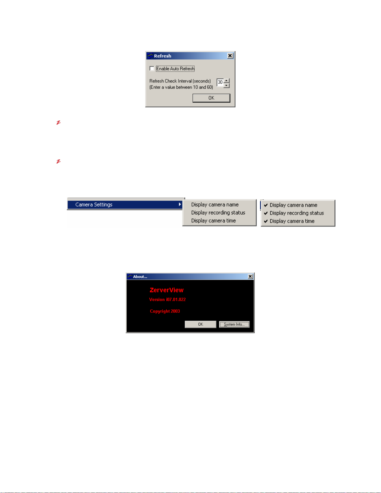
VR-N100U USERS MANUAL
Refresh (F5)
Regardless of whether you utilize the Auto Refresh function, you can manually refresh the VDRView list by
clicking on the F5 function key to discover VR-N100Us on the network. When a refresh is taking place, it will be
indicated by the status bar running across the bottom of the page.
Camera Settings
The final feature available under the Options pull-do wn men u is the Camer a Settings. W it hin VDRVi e w, there are
a few sections such as VR-N100Us and Monitor Cameras pages where live video can be viewed dire ctly from
any of the VR-N100U managed cameras. Within the these camera windows, VDRView offers the ability to
Display Camera Name, Display Recording Status, and/or Display Camera Time within these windows to
provide additional information. These features can be toggled off or on.
4.6.6. Help (About VR-N100U)
Just one command here - About – to open a dialog box t hat displays the VDRV iew version, copyright, and provi de the abilit y
to access the Microsoft System Information page. By clicking on the OK button, it will close out this window.
Page 60 of 98 All Items Are Subject To Change Without Notice Feb. 2004 Rev 1.0
Page 61

VR-N100U USERS MANUAL
4.7. Definition of Navigation Tabs
In addition to the toolbar icon shortcuts, VDRVie w has organized the m ain utility pages usin g tabs. The following sec tions will
describe in detail the available features and functions asso ciated with each navigation tab and its associated page.
VDRView also provides the following shortcut icons to navigate between the different pages.
4.7.1. Zerver Center
When VDRView is launched, the d efault displayed page is al ways Zerver Center where a summary of all VR-N100U securit y
appliances are listed, whether discovered or not. On this page, the applicable functions include setting up the discovery
methods and communication modes, retrieve information summary, setting up IP addr es s, and the ab ilit y to sim ultaneo usl y log
into or out of multiple VR-N100Us. The name, type, IP address, how acquired, default name, discovery method and login
status are available. There is no other product that can offer LAN and WAN management from a single applic ation interface
and provide complete secure communication using SSL to encrypt/decr ypt data and video across the internet. In addition to
this, it is very easy and straight forward.
A refresh shortcut icon is available as it is frequently used during discovery for VR-N100Us.
Page 61 of 98 All Items Are Subject To Change Without Notice Feb. 2004 Rev 1.0
Page 62

VR-N100U USERS MANUAL
NOTE: You can also log directly into VR-N100U via the web browser using the IP address or server name.
4.7.2. VR-N100Us
Management and configuration of all cameras across VR-N100Us can be easily acc omplished within the VR-N100U page. All
changes are applied immediately to the cameras.
Camera Preview
When a camera is selected, the live video feed will be presented in th e camera preview window. At any time, if
you click on any location within the camer a preview window, a PTZ camera will automatically center t he view at
that position (if physically capable).
VR-N100U Camera List
The devices are organized in a logical tree structure. By double-clicking on a VR-N100U, its corresponding
cameras will be displayed. The camera’s current recording status, name, type and user level is provided.
Page 62 of 98 All Items Are Subject To Change Without Notice Feb. 2004 Rev 1.0
Page 63

VR-N100U USERS MANUAL
Filter Camera List
VDRView can also filter the camera list based on type (PTZ , MD or all) to make viewing the cameras easier for
the user.
Camera Status Legend
A legend describing the camera information is also provided to assist the user to easily identif y the recording
status by color, type listed in the brackets, and the current access level for each camera.
Preview Camera Window
If you double-click on a camera or select (highlight) a camera and then click on the Preview Camera button, the
live image from that camera will be displayed in t he Camera Preview window. Below the window, a set of se lf
explanatory control buttons are available. Some of these buttons may not applicable to certain cam era types
such as the pan right/left and tilt up/down on a fixed camera.
Camera Configuration
A summary of the current camera configuration is automatically displayed if there is a camera being previewed. If
a camera is selected and not previewed, an empty summary will be displayed. If no camera is sel ected, then
there would be no summary. The information may vary between different types, makes and models as onl y the
applicable fields will be displayed.
.
Page 63 of 98 All Items Are Subject To Change Without Notice Feb. 2004 Rev 1.0
Page 64

VR-N100U USERS MANUAL
The editable fields are Camera Name, Video Storage (# of days), and Frame Rate (fps) for all camera models
while Angle Step, Zoom Step and Auto Pan Frequency apply only to PTZ type cameras. Once the new
information or setting is specified, click on the save button to activate it.
Advanced Settings
In addition to these controls, VDRView allows the ability to change low-level advanced parameters for each
camera by selecting the Advanced Settings button. For details regarding settings for specific camera
makes/models, please refer to the camera’s users manual or section 5.2 Network IP Cameras.
Preset Positioning
When a PTZ camera is previewed, there is the a bility to choose a selected preset position or save a position with
the Preset Position buttons.
Clear Preview Panel Contents
For all cameras, the Clear Preview Panel Contents button will remove the camera that is currently being
previewed.
Print Panel Contents
For all cameras, the Print Panel Contents button will print a screen shot of the current previewed camera
window.
.
Discover
This button will invoke an automatic camera discovery for all VR-N100U applia nces for which you are currently
logged into. All newly discovered cameras will automatically be configured and available in the Camera List.
4.7.3. Web Connect
VR-N100U is a security appliance, thus does not use a keyboar d, monitor or mouse. In order to manage the devic e, you must
either log into VR-N100U directly via a web browser or utilize the VDRView client soft ware utility. To eli minate having to s witch
between VDRView and your web browser, the Web Connect page will automatically open up your web browser within this
VDRView page and allow you to directly access the VR-N100U. When W eb Conn ect is selected, you will be prompted with the
VR-N100U List dialog box that lists all of the security app liances that you have successfully logge d into. Precede to dr ag-anddrop the VR-N100U that you wish to connect to onto the blank Web Connect page. VDRVie w will automatically launch your
web browser and direct it to that particular VR-N100U.
Page 64 of 98 All Items Are Subject To Change Without Notice Feb. 2004 Rev 1.0
Page 65

VR-N100U USERS MANUAL
Once logged directly into the VR-N100U web server, close out the VR-N100U List dialog bo x and proceed to administer the
VR-N100U. Refer to Chapter 3 VR-N100U Overview for details.
4.7.4. Monitor Cameras
VDRView can also function as a virtual video multiplexer to allow as many as 16 camer as to be simultaneously displa yed in a
view and supporting an unlimited number of custom configurations.
1. Select the Monitor Cameras page tab or the shortcut icon.
2. If no saved camera views exist, proceed to select New View from either the toolbar icon or the camera views pulldown menu. This will open the Create New Camera Vi ew dialog box. Proceed to sp ecify the View Name, determine
the Number of Cameras for this view (1, 2, 4, 5, 6, 9 or 16), Camera Layout and the optional Notes/Description.
3. Once you click on the OK button, the generic template for that number of views will display.
Page 65 of 98 All Items Are Subject To Change Without Notice Feb. 2004 Rev 1.0
Page 66

VR-N100U USERS MANUAL
4. On the left side of the page, click on Load Camera List button to open the Camera List dialog box. From within this
window, you only need to drag-and-drop the cameras which you want to use for this view into the corresponding
blank camera window so that VDRView can link that camera into the view. Cameras can be from the same or
different VR-N100Us. Once you are done, you can close the dialog box.
5. Immediately, the live video feed should be displayed in the corresponding New Vie w along with the current view
information on the left side of the page.
6. The 5 camera view is uniq ue in that VDRView offers a larger 6th preview window where the various cameras autoswitch onto this window. For this specific camera view, we have a control panel that offers the ability to
Page 66 of 98 All Items Are Subject To Change Without Notice Feb. 2004 Rev 1.0
Page 67

VR-N100U USERS MANUAL
identify/specify which camera is displayed on the lar ger preview window, enable or disable the auto switch ing, specif y
the time interval between the switching, as well as clear preview window.
7. When selecting the Full Screen button, a new window opens up that displa ys only the cameras without all of the
menus, icons or information associated with the standard view. This is available for all view options.
8. If you are satisfied with the current view, you can proc eed to Save View by selecting the toolbar icon or from the
Camera Views pull-down menu. You can create and save an unlimite d number of views onto your workstation. At any
time, you can Open or Edit/Delete a view.
9. When you are done with Monitor Cameras, we recommend that you always
utilize resources if left active. You will be prompted with a dialog box to reconfirm your action.
Close View as each view will continue to
4.7.5. Search/Playback
As with the VR-N100U administration page, you can also Search/Playback any video that has already been captured with
VDRView.
1. Proceed to select the Search/Playback navigation tab or click on its shortcut icon. It will present a list of discovered
VR-N100Us and their camera lists.
Page 67 of 98 All Items Are Subject To Change Without Notice Feb. 2004 Rev 1.0
Page 68

VR-N100U USERS MANUAL
2. Now locate the camera from which you want to search the archive on. You can do this by either double-clicking the
camera from the camera list or inputting the camera name in the corresponding field.
3. Next you must specify the date and time range (start to end) of the search, and then click on the Search button. If
you wish to open a new window for the search, select Open New Window option and then click Search.
4. If the search is successful, then it will begin to pla yback the video directly from the VR-N100U. You can select the
speed, playback control, as well as export to an ISO-9660 image file for download and recording the video clip ont o
your local CD/DVD burner.
5. Just like some of the other pages, you can print or clear the search panel.
6. If you opened multiple search windows, please close them up as they do take up unnecessary resourced.
NOTE: Search/Playback can also be accomplished directly from VR-N100U via the web browser.
4.7.6. Motion Log
If any cameras were setup to utilize motion detection recording, then VDRView would be able to provide access to all of the
motion logs captured by VR-N100U.
1. Proceed to select the Motion Log navigation tab. It will pr esent a list of discovered VR-N100Us. Precede to dragand-drop the VR-N100U that you wish to connect to onto the b lank Motion Log page. VDRView will automatically
launch your web browser and direct it to that particular VR-N100U.
Page 68 of 98 All Items Are Subject To Change Without Notice Feb. 2004 Rev 1.0
Page 69

VR-N100U USERS MANUAL
2. As you can see, a complete list of captured motion logs in chron ological order is presented for that particular VRN100U. A motion threshold level indicator is also presented for each motion l og. All motion logs are available for
viewing from the playback window as well as the option to export to an ISO-9660 image.
NOTE: To ensure that it does not take up too much overhead, it is recommended that the administrator periodically check the
log and clear (delete) any unnecessary Motion Log files.
4.7.7. Reflash
Use the Zerver Information shortcut to determine the version number of the firmware on the selected VR-N10 0U. To update
your VR-N100U, proceed to follow the steps below.
1. Download the latest reflash file to a location on your local hard drive or network. The file has a .BIN extension.
2. In the VDRView list window, select the Reflash navigation tab. This will prompt you with the VR-N100U List di alog
box from which you drag-and-drop the VR-N100U you want to upgrade onto the Reflash page. You can then close
the VR-N100U List dialog box after the Software Update page is opened up within VDRView.
Page 69 of 98 All Items Are Subject To Change Without Notice Feb. 2004 Rev 1.0
Page 70

VR-N100U USERS MANUAL
3. Select the Browse button to open up a Choose File dialog box. Locate the VR- N100U .BIN firmware file that you
downloaded from the web site, select the file and click on the Open button. If you selected a firmware file that is older
than the one currently installed on the selected V R-N100U, a warning screen will appear. Click on the Yes button to
continue.
4. After the firmware is specified, proceed to click on the Update Image button to execute the firmware reflash process.
5. Watch the Status section of the Reflash Firmware screen. It describ es what the VR-N100U is doing and where it is in
the reflash process. You can follow the process by monitoring the Status displayed in the Reflash Inform ation screen
on your monitor, or by tracking the Status indicator light (the leftmost light) or LCD Display on the front of the VRN100U unit.
NOTE1: While the reflash is in pr ogress, the Status light will flash green an d amber. The buttons on the Reflash Information
screen are grayed out during this process so you cannot accidenta lly interrupt the reflash. It is absolutely critical that
you do nothing that will stop this process, including remov ing power from the unit. If you do, you will almost certainly
corrupt the flash memory, resulting in a dysfunctional unit.
NOTE2: The firmware reflash procedure will take a few minutes and during this process, the VR-N100U will be offline.
NOTE3: You can also reflash your VR-N100U using FTP. The instructions for an FTP reflash can be found in s ection 6.4 User
FTP Client to Flash VR-N100U of this manual.
Page 70 of 98 All Items Are Subject To Change Without Notice Feb. 2004 Rev 1.0
Page 71

VR-N100U USERS MANUAL
5. SUPPORTED DEVICES
The following sections will provide information surrounding the various VR-N100U supported devices.
5.1. Hard Disk Drive Specifications
VR-N100U supports onboard RAID to offer data integrity for the captured video. The recommende d VR-N100U hard drives
should meet the following criteria:
Form Factor 3.5” half-height required
Interface ATAPI 40-pin ATA/100 or ATA/133
Maximum rpm 7200 or faster preferred
Quickest Seek Times 9ms or faster preferred
Maximum Cache 8MB or higher preferred
Drive Setting MASTER required
Brand Maxtor and Seagate preferred, and always use same make/model for the RAID set
NOTE1: In some instances, VR-N100U has been forced to utilize the slower 5400 rpm rated hard drives due to the lack of
available drive models supporting the above specifications from the leading drive manufacturers.
NOTE2: VR-N100U has the ability to expand the video storage capacity by utili zing the onboard LVD160 SCSI.
5.1.1. Configuring the Hard Drives
When the hard drives are first recognized by VR-N100U as new storage devices, it will pr ompt the user to configure the drives.
If multiple drives are recognized, the available RAID c onfiguration options will be pr ompted. Since VR-N100U applia nces are
normally preconfigured with four (4) of the same make/model recommended hard disk drives, the use r does not have to worry
about configuring the hard drives. However, if for any reas on, on e or m ore drives are not config ured, yo u had to add/re move a
device, or delete/recreate the RAID, follow the instructions on the Devices section under the System Administration Utilities
page.
Page 71 of 98 All Items Are Subject To Change Without Notice Feb. 2004 Rev 1.0
Page 72

VR-N100U USERS MANUAL
5.2. Network IP Cameras
VR-N100U is designed to support the latest IP cameras from JVC. Unfortunately, each make as well as model utilizes different
protocols, and offer slightly different features and functions. Therefore, camera support will be an ongoing process for VRN100U. Below is a list of supported IP cameras at the time this manual was published.
NOTE1: Please visit the various network camera manufacturer web sites for detail specifications and camera firmware
updates. All network cameras should have the latest available firmware and set to manufacturer’s default.
Below is a list of JVC network IP cameras that are currently supported or in the process of being supported.
VN-C10U Fixed, Motion Detection Supported
VN-C11U Fixed, Motion Detection Supported
VN-C30U PTZ Supported
Details regarding the advanced settings for the above network IP cameras supporte d by VR-N100U are listed below.
NOTE1: Always make sure that your JVC network cameras are flashed with the latest firmware version prior to using the
device with VR-N100U.
NOTE2: For more detail information regarding the JVC devices, please visit their web site at www.jvc.com
http://pro.jvc.com/prof/main.jsp
.
Advanced Settings for VN-C10U
Page 72 of 98 All Items Are Subject To Change Without Notice Feb. 2004 Rev 1.0
JVC VN-C10U Configuration (Fixed Motion Detection Network Camera)
Resolution 160x120, 320x240, 640x480
Quality Compression Rate
Balance
Brightness
Backlight
Shutter Shutter Speed
Motion
Detection
Frames per
Second
Automatic White Balance
Red Balance
Green Balance
NOTE: RED & GREEN gains are only applicable if Automatic WHITE is OFF
Automatic Gain Control
Saturation
Backlight Compensation
Backlight Compensation Area
@ 160x120 Max 30 fps
@ 320x240 Max 30 fps
@ 640x480 Max 8 fps
or
Page 73

VR-N100U USERS MANUAL
Advanced Settings for VN-C11U
JVC VN-C11U Configuration (Fixed Motion Network Camera)
Resolution 160x120, 320x240, 640x480
Quality Compression Rate
Balance
Brightness
Backlight
Shutter Shutter Speed
Motion
Detection
Frames per
Second
Automatic White Balance
Red Balance
Green Balance
NOTE: RED & GREEN gains are only applicable if Automatic WHITE is OFF
Automatic Gain Control
Saturation
Backlight Compensation
Backlight Compensation Area
@ 160x120 Max 30 fps
@ 320x240 Max 30 fps
@ 640x480 Max 8 fps
Advanced Settings for VN-C30U
JVC VN-C30U Configuration (PTZ Network Camera)
Resolution 160x120, 320x240, 640x480
Frames per
PTZ
Lens Control
Quality Compression Rate 1 to 7
Balance
Brightness
Backlight
Shutter Shutter Speed 1/60 or 1/100
Second
Presets 10 total
Auto-Pan Camera Never, Every 15 sec/30 sec/1 min/2 min/5 min
Zoom (Optical 15x) 0 to 100
Focus
Iris
Automatic White Balance Off or On
Red Balance 0 to 100
Green Balance 0 to 100
NOTE: RED & GREEN gains are only applicable if Automatic WHITE is OFF
Automatic Gain Control Off or On
Saturation 0 to 49
Backlight Compensation Off or On
Backlight Compensation Area Top, Bottom, Left, Right, Center
@ 160x120 Max 15 fps
@ 320x240 Max 10 fps
@ 640x480 Max 3 fps
Auto Focus (Toggle between Auto and Manual)
Manual Focus 0 to 100
Auto Iris (Toggle between Auto and Manual)
Manual Iris 0 to 100
Page 73 of 98 All Items Are Subject To Change Without Notice Feb. 2004 Rev 1.0
Page 74

VR-N100U USERS MANUAL
5.2.1. Testing Network IP Cameras
If the network IP camera that you are using with VR-N100U is not being recognized or is not functioning correctly, please verify
the following:
1. Is the network IP camera make and model supported by my VR-N100U security appliance’s firmware?
2. Does the network IP camera have the latest firmware version?
3. Is the network IP camera attached to th e VR-N100U backchannel (connected to the dedicated unmanaged layer 2
10/100 Mbit switch that is utilized by VR-N100U) using a CAT5/CAT5e Ethernet cable?
4. Is the network IP camera using the camera manufacturer’s recommended power supply?
5. Are any of the LED lights on the network IP camera ON or show any activity?
6. Was the VR-N100U appliance online before you connected and powered on the network IP camera?
7. When you tried to have VR-N100U DISCOVER the cameras, did any of the other cameras get recognized and
configured automatically by VR-N100U?
8. In the camera window on VR-N100U’s Camera page, is there any message stating “camera not respo nding”?
If you have verified all of the above, then you must proceed to remove that possible defective camera off of the VR-N100U
backchannel and proceed to test it as an individual device on your net work using the software utility that came with it or try
logging directly into the camera’s web server for further investigation. Contact the camera manufacturer’s technical supp ort
team to assist you in troubleshooting the device.
9. Once you have res olved the issue with the network IP camera and rese t to its default settings, you can proceed to
add it to the VR-N100U backchannel and try to have VR-N100U rediscover it.
Page 74 of 98 All Items Are Subject To Change Without Notice Feb. 2004 Rev 1.0
Page 75

VR-N100U USERS MANUAL
5.3. Network Enablers
VR-N100U is designed to support the latest network enablers for anal og cameras (a.k.a. video server or encoder devices)
from major manufacturers. Unfortunately, each make as well as model utilizes different protocols, and offer slightly different
features and functions. Therefore, network enabler support will be an ongoing process for VR-N100U. Below is a list of
supported network enablers at the time this manual was published.
NOTE: Please visit the JVC web site for detail specifications and camera firmware updates. All network enablers should have
the latest available firmware and set to manufacturer’s default.
Below is a list of JVC network enablers (a.k.a. video server or encod er devices) that are currently supported or in the process
of being supported.
VN-A1U 1-Channel, Motion Detecti on Supported
Details regarding the advanced settings for the above network enables supported by VR-N100U are listed below:
Advanced Settings for VN-A1U
NOTE1: Always make sure that your JVC network devices are flashed with the latest firmware version prior to using the
device with VR-N100U.
NOTE2: For more detail information regarding the JVC devices, please visit their web site at www.jvc.com or
http://pro.jvc.com/prof/main.jsp
.
5.3.1. Testing Network Enablers
Page 75 of 98 All Items Are Subject To Change Without Notice Feb. 2004 Rev 1.0
Page 76

VR-N100U USERS MANUAL
5.4. Switches
VR-N100U’s architecture allows the networked security appliance to be a completely non-evasive system. For the
Backchannel (LAN2), a dedicated switch is utilized to enable up to 16 network enabled cameras to be managed by VRN100U. Using a dedicated high-quality Unmanaged La yer 2 24-Port 10/100 Mbit Fast Ethernet, VR-N100U is capable of
supporting 30 fps for each individual camera. However, we have d iscovered that some switches offer very poor performance.
Therefore, we have provided a few recommended high-quality Unmanaged Switches:
LinkSys EF3124 24-Port Switch
LinkSys EF4124 24-Port Switch
LinkSys SR224 24-Port Switch
LinkSys SR2024 24-Port Switch
Below is an example of how the backchannel of VR-N100U should be configur ed. As you can see, only the network cameras
are attached to the switch along with LAN2 of VR-N100U. For further information, refer to section 2.4.5 Setting Up the
Backchannel.
NOTE1: Maximum configuration requires 17 ports (16 cameras and 1 for VR-N100U), thus we recomme nd high-quality 24-
port Unmanaged Layer 2 Fast Ethernet switches for each VR-N100U.
NOTE2: High-quality 24-port Unmanaged Gigabit Sw itches can also be utilized.
NOTE3: Chaining 4 and/or 8 port switches is NOT RECOMMENDED as it causes unnecessary extra ho ps that have been
found to cause performance and reliability problems.
Page 76 of 98 All Items Are Subject To Change Without Notice Feb. 2004 Rev 1.0
Page 77

VR-N100U USERS MANUAL
6. TECHNICAL TIPS AND TROUBLESHOOTING
This section is designated for trained technical personnel onl y. Do not attempt to make any changes unless you have been
instructed by Technical Support personnel. Any unauthorized changes or tampering of your VR-N100U will automatically
void your warranty.
6.1. Industrial Server Board
The main components that makes up the VR-N100U security appliance’s Industrial Server Board is outlined in the following
sections.
Page 77 of 98 All Items Are Subject To Change Without Notice Feb. 2004 Rev 1.0
Page 78

VR-N100U USERS MANUAL
6.1.1. Processor
Due to the optimized and multi-threaded Operating System that is installed on the industrial server b oar d, VR-N100U is abl e t o
achieve fast performance utilizing Intel Socket 370 based processors on the embedde d platform. The board is designed to
automatically detect and support a wide variety of these processors.
NOTE: The VR- N100U comes standard with the fastest Intel Server Processor and hig hest quality low-profile heat sink fan
integrated onto the system.
6.1.2. Memory
The VR-N100U comes standard with 512MB of total memory.
NOTE1: The VR-N100U comes standard with the maximum memory configuration (512MB of PC133).
NOTE2: 512MB SDRAM DIMMs are NOT supported, therefore you must use two (2) 256MB SDRAM DIMMs to achieve the
maximum memory capacity .
6.1.3. Onboard ATAPI
The board comes fully equipped with the multiple onboard ATAPI/IDE Channels. It is capable of supporting any ATAPI-based
devices. The ATAPI device can be manually set to support any of three settings (Master, Slave or Cable Select).
VR-N100U offers onboard RAID storage, therefore four identica l hard drives should be install ed in the VR-N100U Rackmount
System. All hard drives must be set to MASTER and utilize IDE2, IDE3, IDE4 and IDE5 Channels only.
Channel Maximum Speed Channel Maximum Speed
NOTE1: ‘*’ IDE0 is occupied by the onboard non-volatile flash disk, thus we recomme nd not to attach any devices to this
NOTE2: ‘**’ IDE1 is currently not used by VR-N100U and its IDE cable will not be attached to a device at this time.
NOTE3: ‘**’ IDE2 to IDE5 are used for the four (4) VR-N100U RAID hard drives.
NOTE4: We recommend that you utilize ANSI standard 40-pin 80-conducted IDE Cables for ATAPI Channels (IDE1 and
IDE 0* ATA/100* IDE 4** ATA/133
IDE 1 ATA/100 IDE 5** ATA/133
IDE 2** ATA/133
IDE 3** ATA/133
channel.
above). The IDC connector MUST HAVE all 40 pins open on the (Blue) host connector.
6.1.4. Onboard SCSI
The board can come standard with an onboard SCSI Channel. T he Adaptec Ultra160-LVD/SE SCSI is capable of supporting
any SCSI-1, SCSI-2, SCSI-3, Narrow, Ultra, Wide, Ultra Wide, LVD160, and LVD320-based devices. The SCSI device support
is dependent on the VR-N100U installed device drivers.
SCSI ID Maximum Speed SCSI ID Maximum Speed
Page 78 of 98 All Items Are Subject To Change Without Notice Feb. 2004 Rev 1.0
ID #0 160 MB/s ID #8 160 MB/s
ID #1 160 MB/s ID #9 160 MB/s
ID #2 160 MB/s ID #10 160 MB/s
ID #3 160 MB/s ID #11 160 MB/s
ID #4 160 MB/s ID #12 160 MB/s
ID #5 160 MB/s ID #13 160 MB/s
ID #6 160 MB/s ID #14 160 MB/s
ID #7* 160 MB/s ID #15 160 MB/s
Page 79

VR-N100U USERS MANUAL
NOTE1: “*” The default SCSI ID for the onboard Adaptec LVD160 Chipset is ID #7 with both Parity and Termination Enabled.
NOTE2: Various SCSI devices can be daisy-chained on the SCSI bus, however the bus speed and c able length restrictions
will be governed by the slowest attached SCSI device type.
NOTE3: Proper SCSI etiquette (unique SCSI IDs, SCSI termination (end devices only w ith Active termination r ecommended),
proper SCSI cable lengths) must be maintained at all items to ensure the highest performance an d reliability.
6.1.5. Onboard Dual Ethernet
The VR-N100U board comes standard with dual onboard 10/10 0 Network Interface Connectors (NICs) for providing a higher
level of flexibility, connectivity and functionality.
NOTE1: LAN1 is designed for use as the VR-N 100U front-channel for connectivity to the company’s main network backbone.
NOTE2: LAN2 is designed for use as t he VR-N100 U backch annel fo r manag ing up to 16 ca mer as and shou ld b e connected to
the dedicated “camera” switch on port 17 of the 24-port switch.
6.1.6. PCI Expansion Slot
The VR-N100U board comes standard with an onboard 32-bit PCI Expansion Slot. T his Expansion Slot is designed to be
utilized with the optional Video Life Cycle Management function of VR-N100U.
NOTE1: A third party PCI Riser Card may not work with the VR-N100U b oard.
6.1.7. USB
The board is designed to support dual onboard USB channels.
NOTE: The current version of VR-N100U does not incorporate support for the USB, thus please do not attempt to attach any
USB device to the dual USB ports of the 19” 1U rackmount.
6.1.8. COM Port
The board has a COM port on the rear, however, it is not utilized by VR-N100U. Therefore, please do not attempt to attach any
serial cable or device to it.
Page 79 of 98 All Items Are Subject To Change Without Notice Feb. 2004 Rev 1.0
Page 80
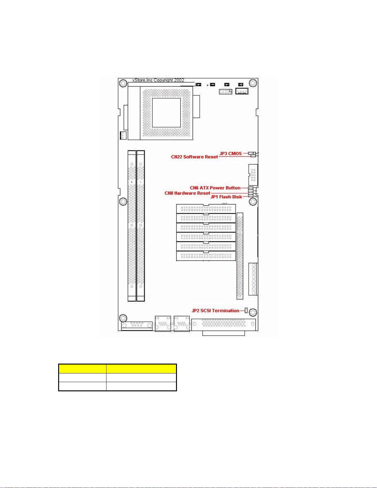
VR-N100U USERS MANUAL
6.2. Jumper Settings
The Industrial Server Board utilizes multiple default jum per settings for use with the VR-N100U securit y appliance and they are
outlined in the following sections.
6.2.1. JP1: Flash Disk
Page 80 of 98 All Items Are Subject To Change Without Notice Feb. 2004 Rev 1.0
Options Settings
Master 1-2: Short
Slave 1-2: Open (default)
The embedded VR-N100U operating system and ap plication are stored on a no n-vola tile flash disk that is attached to
the IDE 0 Channel. The setting for the flash should always be set to MASTER and no other device should be
attached to the IDE 0.
NOTE: DO NOT attempt to change the Flash Disk default setting on your VR-N100U unless instructed by Technical
Support personnel.
Page 81

VR-N100U USERS MANUAL
6.2.2. JP2: SCSI Termination
For the on board Adaptec LVD160 SCSI Termination to be ena bled, both the JP2 m ust be OPEN (not jumpered) and
Options Settings
Disable 1-2: Short
Enable 1-2: Open (default)
the SCSI Termination option in the Adaptec BIOS be enabled (both default settings).
NOTE: DO NOT attempt to change the SCSI Termination setting on your VR-N100U unl ess instructed by Techni cal
Support personnel.
6.2.3. JP3: CMOS
To clear the CMOS setting and have the VR-N100U revert to its default settings, you will need to follow the steps
Options Settings
Normal 1-2: Short (default)
Clear CMOS 2-3: Short
below:
a) Power OFF the VR-N100U
b) Short (jumper) pins 2-3 on JP3
c) Power ON the VR-N100U for 5 seconds
d) Power OFF the VR-N100U
e) Short (jumper) pins 1-2 on JP3 to be able to use the VR-N100U in normal mode
NOTE: DO NOT attempt to reset the CMOS setting on your VR-N100U unless instructed by Technical Support
personnel.
6.2.4. CN6: ATX Power Button
Pin Signal
1 PW_BN +
2 GND
The ATX Power switch is attached to CN6 to enable the ability to power ON and OFF the VR-N100U with the
supplied Rackmount ATX Power Supply.
NOTE1: To power ON, merely press the power toggle button.
NOTE2: To power OFF, press on hold down the togg le button for a few seconds to allow the ATX Power Supply to
properly turn off.
6.2.5. CN8: Hardware Reset
Pin Signal
1 Reset
2 GND
The recessed power reset button on the Rackmount chassis is attached to CN8.
NOTE: It is NOT RECOMMENDED to conduct a hard reset on the VR-N100U as it will cause a “dirty shutdown” and
cause the appliance to be temporarily disabled until the devices have completed a resynchronization.
Page 81 of 98 All Items Are Subject To Change Without Notice Feb. 2004 Rev 1.0
Page 82

VR-N100U USERS MANUAL
6.2.6. CN22: Software Reset
Pin Signal
1 Reset
2 GND
The software reset is a means to manually reset the appliance temporarily back to manufacturer’s default settings.
NOTE: VR-N100U rackmount systems do not utilize the manual software reset option.
6.3. BIOS
The settings for the customized Phoenix-Award BIOS for the industrial server board hav e been optimized for the VR-N100U
security application. No changes to the CMOS are required.
6.4. Adaptec SCSI BIOS
The onboard Adaptec SCSI BIOS settings for the server board have been for the VR-N100U securit y application. No chan ges
to the Adaptec SCSI BIOS are required. The default settings are:
SCSI Controller ID 7
SCSI Controller Parity Enabled
SCSI Controller Termination Enabled
Sync Transfer Rate (SCSI ID #0~15) 160 MB/Sec
Initiate Wide Negotiation Yes
Enable Disconnection Yes
Send Start Unit Command Yes
BIOS Multiple LUN Support No
Include in BIOS Scan Yes
Reset SCSI Bus at IC Initialization Enable
Display <Ctrl><A> Message During BIOS Initialization Enable
Extended Init 13 Translation for DOS Drives > 1 GByte Enable
POST Display Mode Verbose
SCSI Controller Int 13 Support Enabled
Domain Validation Enabled
Support Removable Disks Under Int 13 as Fixed Disabled
Adaptec Settings Defaults
Page 82 of 98 All Items Are Subject To Change Without Notice Feb. 2004 Rev 1.0
Page 83

VR-N100U USERS MANUAL
6.5. LED Panel with Keypad and LED Indicators
The VR-N100U appliance is designed to utilize the LCD Display Panel, Keypad and LED Indicators. This LCD Display
supports 2-lines of 16 alphanumeric characters, has four (4) access buttons, and als o includes the four (4) LEDs that provide
important status information for various components. These are utilized by the VR-N100U to provide important information
regarding the current status of the appliance. These include the Status Activity, Network Activity (LAN1), 10/100 Network
Connection Status (LAN1), and Device Activity for all ATAPI and SCSI Channels. The phases of the li ghts provide information
about the operation of the VR-N100U.
6.5.1. LCD Panel
When the VR-N100U starts up, the LCD display will begin displa ying messages. It will keep you informed of the steps the
system is going through during the boot up process and is summarized on the chart below. This comprehensive display
graphically illustrates the steps of each process that can be performed using the LCD Panel.
The LCD Panel begins by displaying the message Hardware POST with a version number on the second line (POST stands
for Power-On Self-Test). The Status LED (the first indicator light on th e left) will display s olid red. As VR -N100U boots the OS
(operating system) and detects the drives, those messages will be display on the Pane l. When the boot up process goes into
the next phase, the Status LED changes to solid amber an d the versi on nu m ber of the fir m ware is displ a yed on th e Pa nel. T he
system then attempts to acquire an IP address, checks the drives, and starts networking services. If a DHCP Server is running
on the network, VR-N100U dynamically acquires an IP address. The Status light turns solid green and the default Server
Name displays on the LCD Panel with the IP address on the n ext line. The Server Name and IP address will continue to
display until an event occurs on the VR-N100U, or the user pushes a key. This is called the Steady State Display, and it
means everything is running. If the VR-N100U did not dynamically acquire an IP address, it will assign itself the address
10.10.10.10 and the Status light will slowly blink amber. When a VR-N100U comes up tens, it means that a Static IP address
must be assigned to the system before anything else can b e done with it. You will need to go your net work admin and get an
IP address, the Subnet Mask, and the address of the Default Gateway.
6.5.2. Keypad
Each key has a different function, illustrated by a directional arrow just above and to the left of the key. From left to right, the
first key is the Up key. The next key is the Down key. The third key is the Back key. And, the last key, the key on the right, is
the Enter key.
Up Down Back Enter
Page 83 of 98 All Items Are Subject To Change Without Notice Feb. 2004 Rev 1.0
Page 84

VR-N100U USERS MANUAL
6.5.3. LED Indicators
The LEDs are identified by a keyword above each light on the unit and b y the complete name of the LED in the following
graphic. The LED lights can flash green, amber, or red, each color in dicating a different state or activity of the system. The
chart below summarizes the LED indicators.
LED Label Color Aspect Description
Status
Network
Network Activity
(LAN1-Backbone)
10/100
Network Speed
(LAN1-Backbone)
Drive
Drive Activity
Power-On
the self-test is completed, the LED transitions to amber and
Red Solid
Amber Solid
Green Solid
Amber Flashing
Green/
Amber
Green Flashing Indicates that network traffic from an external source
Amber Flashing Indicates that the VR-N100U is transmitting
Amber Solid Your network speed is 10 Mbps.
Green Solid Your network speed is 100 Mbps.
Green Flashing An IDE drive is reading or writing data.
Red Flashing A SCSI drive is reading or writing data.
Blinking
No Light Indicates that there is no network link visible to the VR-N100U
continues the power-on process.
Power-Off
which power can be safely turned off on the VR-N100U
Power-On
has completed the self-test and is booting the OS and application.
Indicates that VR-N100U is completely initialized. It has acquired
and IP address and is operational.
Indicates that VR-N100U was unable to acquire an IP address. It
defaults to the address 10.10.10.10.
Indicated that VR-N100U is reflashing the firmware.
NEVER INTERRUPT THIS PROCESS!!!
: Solid Red during power-on indicates a self-test. When
: Solid Red during power-off indicates a safe halt, after
: Solid Amber during power-on indicates that VR-N100U
Status
The Status LED, the first light on t he left, cycles through its power-on sequence as the VR-N100U boots up. It
starts out solid red during self-test. Solid amber indicates the server is bo oting the OS and the application. Solid
green indicates the VR-N100U has successfully powered on and dynamically acquired an IP address. The
Status light will remain solid green throughout normal operation. If the Status light slowly blinks amber, VRN100U has failed to dynamically acquire an IP address. You must simply use one of the four methods outlined in
the manual to manually acquire an IP address. When VR-N100U is in the process of updating or refl ashing the
VR-N100U firmware, the Status LED will flash quickly between green and amber. Under no circumstances
should the process be cancelled or power be removed from the u nit during the reflash. A partial or terminated
operation may result in a dysfunctional unit.
Network
The Network Acti vity LED flashes green when there is network traffic from an external source on LAN1, the
network backbone. When the Network LED flashes amber, it means the VR-N100U is transmitting video from the
cameras and/or being accessed over the network.
NOTE: Only LAN1’s Network LED is available because the LCD Module was originally designed with the
previous generation server board which utilized only a singl e network connection.
Page 84 of 98 All Items Are Subject To Change Without Notice Feb. 2004 Rev 1.0
Page 85

VR-N100U USERS MANUAL
10/100
The Network Speed LED will be either solid amber, or solid green. Amber indicates the LAN1 camera
backchannel network speed is 10 Mbps. Green indicates the LA N1 camera backchannel network speed is 100
Mbps. When the LED is red, there is no network link visible to the server on LAN1.
NOTE: Only LAN1’s 10/100 LED is available because the LCD Module was originally designed with the
previous generation server board which utilized only a single netw ork connection.
Drive
The Dri ve Activity LED lights up whenever data is moving to or from an IDE device or SCSI device. A flashing
green light indicates an attached IDE drive is reading or writing data. A flas hing red light i ndicates a SCSI devic e
is reading or writing data. A flashing amber light indicates both IDE and SCSI devices are active. The Drive
Activity LED does not differentiate between reading and writing data.
6.5.4. Entering the Address
If you want to change the IP address of your system, follow the steps below.
1. Depress the Enter key. The LCD Panel will displa y the message Network Setup…
2. Depress the Enter key. The Panel displays the IP address entry scr een. The cursor will be p ositioned at the location
of the first digit in the first set of numbers. Use the Up and Down arrow keys ( Up increments the number, Down
decrements it) to locate the first number in the IP address. When the c orrect number is displayed in t he first position,
depress the Enter key. The cursor advances to the next pos ition in the IP a ddress. Contin ue to use t he Up a nd Do wn
arrow keys to locate the numbers in the IP address, depressing the Enter key to accept each number. Use the Back
key to move the cursor one position to the left. Don’t forget, if the address you were given has only one or two digits
in any of the number sets of the address, use leading zeroes to pad the number set to three digits. For example, if the
IP address you were given is 195.182.30.4, enter195.182.030.004 in the address fields. When you have finish ed and
have verified that you entered the correct IP address, depress the Enter key.
3. The Subnet Mask entry screen displays. Enter the Subnet Mask us ing the arrow keys as you d id for the IP address.
When you have finished, depress the Enter key.
4. T he Default Gateway address entry screen displays. Enter the address and depress the Enter key. The next screen
inquires if you want to enable the Static IP address and the other addresses you just entered. If you sel ect the Y, the
addresses will be saved and the Static IP opt ions in the TCP/IP Configuration tool in the Network Configurations
Tool Set will be selected. If you select the N, the option to obtain the IP address d ynamically in th at same tool will be
selected. Use the arrow keys to toggle between the Y and N. Depress the Enter key to accept your selection.
5. The next screen that displays asks if you want to reboot the system to apply the addresses you entered. Select the Y
if you are ready to reboot now. Select the N if you plan to change the def ault Server Name. Make your selection an d
depress the Enter key. If you select the Y, the VR-N100U will reboot. The LCD Panel will keep you informed about
what is happening. If you select the N, you will go back to the Network Setup screen.
6.5.5. Renaming Your System
If you want to rename your system, depress the Down key.
1. The Set Server Name– screen displays. Depress the Enter key. T he Edit ServerName screen displays. The Server
Name you enter here can contain up to 24 alp hanumeric characters and the dash ( - ). Use the Up and Down arro w
keys to cycle through the numbers, letters and the dash to spell out the ne w name of your VR-N100U. The valid
characters are arranged in this order: the dash, the numbers 0 through 9, the Capital letters A through Z, and the
lowercase letters a through z. Remember, the Up key goes forward through the characters and the Down key goes
backward. Depress the Enter key to accept the current character and advance the cursor. Depress the Enter key
repeatedly until the Update? Screen displays.
2. If you select the N, you will be returned to the Set Server Name screen and the new Server Name will not be saved. If
you select the Y, the new Server Name is saved. It will go into effect when the system is rebooted. Depress the Enter
key. The Reboot screen displays.
Page 85 of 98 All Items Are Subject To Change Without Notice Feb. 2004 Rev 1.0
Page 86

VR-N100U USERS MANUAL
3. If you select the N, you will be returned to the Set Server Name screen. If you select the Y, the VR-N100U will reboot.
The LCD Panel will keep you informed about what is happening. Only when you reboot the system will the new
addresses and Server Name go into effect.
6.5.6. Rebooting
VR-N100U supports 3 types of reboots and they can be executed from the LCD Display.
# Types of Reboots
1 Normal Reboot
2 Factory Defaults Reboot
3 Safe Halt Reboot
1. When your system is operating normall y, the LCD Pan el will displ ay the Server Name and the IP address , the Steady
State Display. If you want to reboot the system, simply depress the Enter key. You will be prompted for the admin
password. Use the Up and Down arrow keys to cycle through the numbers, letters and the d ash to spell out the
password. This screen did not display the first time you started up the system. The Password entry screen d oes not
display until after you have setup your syste m in the VR-N100U Web bro wser interface. It will display from that point
on whenever you press the Enter key. Depress the Enter key repeatedly to accept the password and advanc e to the
Network Setup screen.
2. Depress the Down key to move through the screens until th e Reboot… screen displays. Depress the E nter key. The
first of the Reboot Type screens displays. There are three kinds of reboots you can perform. A Normal Reboot just
reboots the system. A Factory Defaults Reboot resets all configurable VR-N100U functions to their original, freshfrom-the-factory settings. The contents of the VR-N100U Users List and the Groups List are lost. The Server Name
and all defined Volume Sets are also lost when a reset-to-defaults reboot i s selected. A Pow er Off Reboot will power
down your system using a managed, c ontrolled process designed to protect the syst em’s equipment prior to power
off. The Status light will remain solid red, indicating the VR-N100U can be powered off. Turn the power switch to the
Off position, or unplug the power cord from the outlet. Do not remove the power cord from the system to power it off.
Use the Down key to cycle through the different reboot choices until you get to the one you want. Use the Enter key
to select your choice of Reboot, select the Y on the confirmation scree n and depress the Enter key to begin the
Reboot. The LCD Panel will display progress messages reg arding the state of the reboot.
6.5.7. View Events
The last LCD Panel option is View Events. Depress the Enter key to display the Password screen. Enter your admin pas sword
using the Up and Down keys to display the characters and numbers in the password. Depress the Enter key to accept the
password and display the Network Settings screen. Depress the Down key to cycle to the View Events screen. The current
event will scroll across the screen (the LCD Panel is reading this from the Event Log in the System Utilities). Use the Up and
Down keys to view the other events recorded in the Event Log.
6.5.8. Manual Reboot Status
If the VR-N100U is manually rebooted, the Status LED is the only indicator light that is of concern. The chart bel ow provides
a summary of this information:
LED
Status
If the VR-N100U’s Status LED begins flashing red during a reboot, it indicates a hardware failure on the VR-N100U boar d.
Hardware failures, if they exist, are detected during the power-on self-test and include the following:
Boot RAM failure
RAM failure
Flash failure
Page 86 of 98 All Items Are Subject To Change Without Notice Feb. 2004 Rev 1.0
Interval in
seconds
4 ~ 8 Solid Amber System Reboot
8 ~ 12 Solid Red Safe Halt
12 ~ 16 None – LED Off Factory Defaults Reboot
16 + Original State Ignores the Reset button until pushed again
Color Operation Performed
Page 87

VR-N100U USERS MANUAL
CMOS failure
NIC failure
SCSI failure
LED RED GREEN DESCRIPTION
On Off POST (Power On Self-Test)
Flash 1 Off ROM Checksum Error
STATUS
NETWORK
10/100
DEVICE
Flash 2 Off Memory Error
Flash 3 Off Error as No Bootable Disk
On On Boot up into OS
On/Flash Off Software Controlled
Off On/Flash LAN1 Hardware Activity
Off Off No Network Activity
On Off LAN1 10Mbit Ethernet Connection
Off On LAN1 100Mbit Ethernet Connection
Off Off LAN1 is not Connected
On/Flash Off Device Activity on SCSI Bus
Off On/Flash Device Activity on IDE Channel(s)
Off Off No Device Activity
6.6. Power Supply
The board is also unique in that it has be en designed to support the two most common types of po wer supplies used today
(AT and ATX). This flexibility will allo w it to be installed in nearly all e nclosures. The ATX power suppl y is recommended and
comes standard with all VR-N100U rackmount systems.
NOTE1: When selecting the ATX pow er adapter, do not forget to attach an ATX power switch to CN6 pin set.
Page 87 of 98 All Items Are Subject To Change Without Notice Feb. 2004 Rev 1.0
Page 88

VR-N100U USERS MANUAL
7. GLOSSARY OF TERMS
A version of Ethernet in which workstations are attached b y twisted pair cable, the traditional
10BaseT
100BaseT
1000BaseT
Access Protocol
Access Rights
Access Time
AFP AppleTalk Filing Protocol - An AppleTalk client/server protocol.
Anonymous User
Appliance class Server
Application
Application Launcher
Authentication
Backup Browser
BOOTP
Broadcast
Broadcast Address
Browse List
Browser
Cache
Page 88 of 98 All Items Are Subject To Change Without Notice Feb. 2004 Rev 1.0
cables used for telephone lines. 10BaseT uses star formation and transmits at 10 megabytes
per second (Mbps).
A high-speed LAN, 100BaseT is also called Fast Ethernet. It transmits at 100 megab ytes per
second (Mbps).
A high-speed LAN, 1000BaseT is also called Gigabit Ethernet. It trans mits at 1000 megabytes
per second (Mbps).
A communication methodology that facilitates the transfer of data to and from a networked
computer resource.
A privilege assigned to a user by the VR-N100U admin giving the user the right to View,
Operator or Administer VR-N100U and Cameras.
The amount of time it takes for a storage peripheral to transfer data to the computer.
An FTP client who logs in to a VR-N100U without authentication.
A special purpose network device designed to perform a specific task. This specialized server
has an appliance-like design and behavior. It has a single function, it is inexpensive when
compared with traditional file servers, it is easy to install and operate, it is reliable, and it does
not require the services of a network fileserver to communicate with its clients.
A program that performs a specific function, e.g., a spreadsheet application, or a word
processing application.
A program that automatically starts up or opens an application.
The verification of the identity of a user as a security measure. Passwords area form of
authentication. A user can be authenticated by the Windows Domain, if network integration has
been established, or by VR-N100U, which checks the Users List.
A computer in a domain or NT group assigned by the Mast er Browser to maintain a copy of the
browse list. This copy can be used to rebuild the bro wse list if the Master Browser goes down.
The Master Browser maintains one backup browser for every 32 NT workstation hosts, or ever y
16 Windows hosts in a workgroup or NT Domain.
Bootstrap Protocol - A method of automatically assigning IP addresses. BOOTP works in much
the same way as DHCP, but does not have the range of features of DHCP.
A transmission sent to many unspecified receivers at a time. (A broadcast is sent to ever yone
who has the equipment to receive it.) On an Ethernet, a broadcast packet is one which is
transmitted to all hosts on the network
A central address which will forward any messages sent to it to all user addresses on a network.
A list of the hosts and domains available on a Windows network. The browse list allows
Windows to present other hosts offering network services through a point-and-click user
interface, rather than requiring users to remember the names of remote hosts and services. In
Windows 95, 98 and NT, the browse list is used to construct the view of the network in the
Network Neighborhood and Windows Explorer.
A program that provides the interface to the World Wide Web. It interprets hypertext links and
makes it possible for you to view Web sites and navigate from one Intern et node to another. T he
most popular browsers are those produced by Netscape and Microsoft.
A place that stores information where you can get to it fast.
Page 89

VR-N100U USERS MANUAL
CD burn
CD-R
CD-ROM
Changer
Class C Network
Internet Protocol (IP)
Class C Networks
Client
Compression
Compression
Threshold
Daisy-chain
Data Packet
Datagram
DHCP
Distributed Computing
Environment
Dismount
DNS
DNS Server
Domain
Domain Integration
Domain Name
Page 89 of 98 All Items Are Subject To Change Without Notice Feb. 2004 Rev 1.0
Slang for the process of recording a CD-R, a CD-recordable medium.
Compact Disc Recordable - A recordable CD-ROM, which can be read by normal CD-ROM
drives. Data can be recorded once onto a CD-R, and cannot be changed.
Compact Disc, Read Only Memory - An optical storage medium in disc form that comes with
data already encoded on it in a laser-generated continuous spiral.
A specialized CD/DVD-ROM drive in which more than one CD/DVD ca n be loaded. However,
since a changer has only one read-hea d, only one of the loaded CD/DVD-ROMs can be read at
one time.
Networks are divided into classes and are assigned Internet IP addr ess ranges based on their
network classification.
Networks are small networks of up to 256 workstations. The first three bytes of their IP
addresses identify the network, the last byte id entifies the individual computer on the network.
Class B networks are found in larger organizations. The first two bytes of their IP addresses
identify the network, and the last two bytes identify each of up to 64,000 individual workstations.
A computer that uses the services of another computer, typically a server.
The temporary coding of data in a way that saves storage space or transmission time. The
amount of compression depends on the type and content of the specific file.
A user-configurable setting that defines a percentage of storage space saved above which a
CD/DVD-ROM should be compressed.
A configuration in which devices are connected to each other in seque nce, like a chain of
daisies. The last device in the chain must be terminated.
Information organized into blocks for transmission.
A packet of data and delivery information delivered over a non-guaranteed communications
protocol.
Dynamic Host Configuration Protocol - A method of assigning IP addresses to computers
connected to a local area network (LAN). When a computer requests an address, the DHCP
server selects an IP address from a master list and assigns it to the requestor.
An architecture consisting of standard programming interfaces, conventions and server
functionalities for distributing applications transparently across networks of heterogeneous
computers.
The process of taking a published, or mounted, CD/DVDs off-line so that it is no longer available
to users.
Domain Name System - A distributed database system used by TCP/IP applications to map IP
addresses to their system names. The acronym refers both to the convention for naming hosts
and to the way the names are handled across the Internet.
A computer on the Internet that translates Internet domain names into Internet numerical
addresses, such as 192.186.24.2.
In Windows, a domain is an administrative grouping of hosts. In the Internet world, a domain is a
host-naming convention.
A process in which the Windows Domain becomes available to VR-N100U to provide
synchronization of user and group authentication and access on a secure VR-N100U.
A dot-separated sequence of text strings which uniquely identify a host computer. Domain
names are issued by the National Science Foundation (NSF). The Domain Names have different
extensions based on the category in which the domain belongs: .com & commercial
enterprise.edu & educational institution.gov & government body.mil & the militar y.net & a
Page 90

VR-N100U USERS MANUAL
network.org & a nonprofit organization. There has been a push recently to add more categories
for classifying domains.
Download
Drive Mapping
DVD-ROM
Effective Rights
EIDE
Ethernet
Ethernet Address
Factory Defaults
Reboot
Fast Ethernet
Firmware
Flash Memory
Frame Type
Page 90 of 98 All Items Are Subject To Change Without Notice Feb. 2004 Rev 1.0
To transfer data from a remote computer to your computer via a network connection.
A method of defining a pointer to a data storage location, or drive. The letters of the alphabet are
used as the pointers, giving you 26 pointers to use to describe specific locations. The first five
letters of the alphabet (A through E) are traditionally used to point to local drives (floppy drives,
local hard drives, CD-ROM drives). On the network, a drive mapping serves as a bookmark,
allowing a user direct access to a particular location. A drive letter is used to represent a logical
drive, while a directory path leads to the specific location in the directory structure.
Digital Video (Versatile) Disc, Read Only Memory - A type of read-only optical disc. DVDROMs are similar to CD-ROMs in that the data are stored in a laser-generated continuous spiral
on the disc surface. The difference is that DVD-ROMs store much more data (4.7GB or more) in
smaller pits in tighter circles. Capacity can be increased even more by adding a second layer of
pits over the first, and by using both sides of the disc. Experts believe DVD-ROMs will eventually
replace CD-ROMs.
The actual rights that a user or group has to access a Camera Set or Individual Camera. Access
rights can be granted explicitly, or endowed by inheritance. Admin and users with Manager
rights have unrestricted access rights to all Camera Sets and Individual Cameras. While
effective rights are cumulative, a user or group needs to be granted access rights by means of
only one of these methods (explicit assignment, inheritance, or Manager rights) to effectively
access a Camera Set or Individual Camera.
Enhanced Integrated Device (Drive) Electronics - A second generation IDE drive interface
that increases the previous maximum drive size. The data transfer rate is speeded up to more
than twice that of the IDE. Another name for EIDE is ATAPI.
A standard for connecting computers to a local area network (LAN), Ethernet is the most popular
type of LAN. It sends its communications through radiofrequency signals carried by coaxial cable
or other media. Developed by Xerox, it is sometimes called IEEE 802.3, which refers to the
standard that defines it. The most common form of Ethernet is 10BaseT, which refers to a peak
transmission speed of 10Mbps using copper twisted-pair cable.
The physical address of an Ethernet controller board, expressed as a 48-bit number in
hexadecimal notation. VR-N100U Ethernet addresses will always take the form 00 80 A1 XX XX
XX.
A factory defaults reboot is one of the cycle options associated with the Reset button on the front
of the unit. (See Chapter Seven ΠTechnical Tips and Troubleshooting.) The system goes
through the preparation for reboot by terminating all network connections, writing outstanding
data to the hard drive, and closing all programs. Then, before it begins to start up again, all user
configurable parameters (security, user/group lists, server name, etc.) are reset to the settings
they were assigned at the factory, the default settings.
See 100BaseT
The software embedded in the nonvolatile memory, flash memory, of the VR-N100U, which can
be updated with a new program.
Nonvolatile memory chips that can be reprogrammed with new instructions after the chips have
left the factory.
Data is transmitted on the network in blocks and these blocks are encapsulated by headers and
trailers that describe where the data came from, where it is going, and the size and integrity of
the data. This envelope of information, and the data it encapsulates, is called a packet or frame.
Over the years, different frame headers have been defined and used in data communications
over local area networks (LANs). Each set of frame headers represents a specific frame type. In
order for a device to decode a received frame, it must recognize the frame type used by the
sending node. There are four common Ethernet frame types: IEEE802.3, IEEE 802.2, Ethernet
II, and Ethernet SNAP. A VR-N100U using the IPX protocol supports all four frame types. A VRN100U using the IP protocol supports only the Ethernet II frame type.
Page 91

VR-N100U USERS MANUAL
FTP
Gateway
HFS
Host
Host ID
HTML
HTTP
Hyperlinks
Hypermedia
Hypertext
IDE
Inherited Rights
Interface
Internet
Internet
IP
IP Address
Page 91 of 98 All Items Are Subject To Change Without Notice Feb. 2004 Rev 1.0
File Transfer Protocol - A high level protocol that supports file copying from one system to
another over a TCP/IP connection. FTP requires client and server components.
A program or piece of hardware that passes data between networks, especially between
networks that cannot talk directly to each other because they use different protocols.
Hierarchical File System - A format system in which data are stored hierarchically in directories
and subdirectories (DOS), or folders within folders (Mac).
A computer on the Internet you may be able to log in to by using telnet, get files from by using
FTP, or otherwise make use of.
The portion of an IP address that identifies the host in a particular network. The Host ID is used
in conjunction with the Network ID to form a complete IP address.
Hypertext Markup Language - HTML is used to write pages for the World Wide Web.HTML text
includes markup codes that define fonts, layout, embedded graphics, and hypertext links.
Hypertext Transfer Protocol - These four letters at the beginning of most URLs tell the Web
server how your browser intends to communicate with it. (Two computers need to establish a
communications protocol right away, or they’ll never get around to exchanging data.) The HTTP
protocol is used to transfer a document from the server to your system.
The underlined words or phrases in Web documents you click on to jump to anoth er screen or
page. Hyperlinks contain HTML-coded references that point to other Web pages, which your
browser then jumps to.
Hypermedia integrates text, images, video, and sound into its documents. The elements of
hypermedia documents are linked in an interactive way.
A non-sequential way of presenting information. A system of writing and displaying text th at
enables the text to be linked in multiple ways, to be available at several levels of detail, and to be
powered by hyperlinks to associated documents.
Integrated Device (Drive) Electronics - A hard drive interface that has all of its controller
electronics integrated into the drive itself. This is the standard for most personal computers.
Access rights that are explicitly granted to a Camera Set are inherited by all Camera members.
Access rights that are explicitly granted to a group are inherited by all user members of the
group.
A general means of communication between humans and computers. An interface can use
characters, graphics, and sound to facilitate communication. A Web browser is an example of an
interface.
A collection of packet-switching networks connected by IP routers and appearing to users as a
single network.
A network of networks, the Internet is the world’s largest collection of networks that reaches
universities, government research labs, business organizations, and military installations in most
of the countries around the world.
Internet Protocol -IP is the workhorse protocol of the TCP/IP protocol suite. IP is responsible
for addressing and sending datagrams across an internet. It provides an unreliable,
connectionless datagram delivery service; unreliable because there are no guarantees that an IP
datagram successfully gets to its destination, and connectionless because it doesn’t maintain
any status information about successive datagrams. IP provides best effort service and relies on
ICMP to deliver error messages to the source. Datagrams are handled independently of all other
datagrams, so there is no guarantee they will arrive at the destination in order. Datagrams are
assembled by TCP at the destination.
The address scheme that identifies a computer on the Internet by a uniquest ring of numbers,
arranged in four groups separated by periods, e.g.,123.123.23.2. The IP address is responsible
for moving packets of data from node to node. The Internet authorities assign ranges of numbers
Page 92

VR-N100U USERS MANUAL
to different organizations, which distribute them to their users either dynamically or as
permanently assigned IP addresses. IP operates the gateways that move data within an
organization and to regions and then around the world. Every resource on the Internet must
have an IP address.
IP Broadcast
IP Packet
IPX
IPX Network Number
ISO-9660
Jumper
LAN
LED
Link
Location
Long File Name
LUN
LUN Queuing
MAC
MAC Address
Master
Master Browser
Page 92 of 98 All Items Are Subject To Change Without Notice Feb. 2004 Rev 1.0
An IP address that is used when a host wants to send a frame to every other host on the
network.
A chunk of data transmitted over the Internet using standard Internet Protocol (IP). Each packet
begins with a header containing addressing and system control inform ation. IP packets vary in
length, depending on the data being transmitted.
Internetwork Packet Exchange – NetWare’ network-layer protocol. It handles networking
addressing, routing, and packets. It is the most common of all networking protocols.
An eight-digit hexadecimal number that uniquely identifies a network.
A format standard for CD-ROM disks defined by the International Standardization Organization
(ISO).
A metallic collar that slips over a set of pins to join them together to complete an electrical
connection.
Local Area Network - A network that connects or links together on the same cable computers
that are close to each other, usually in the same building.
Light-Emitting Diode - A type of semiconductor diode that emits visible or infrared light when
current passes through it. Visible LEDs are used as indicator lights; for example, the light that
shows a computer or printer is turned on. Infrared LEDs are used in remote-control devices.
A connection. Two computers can be linked together. Link can also refer to a pointer to a file that
exists in another place. Rather than have a copy of a particular file reside in many places, for
example, some file systems enable a filename to point to another file. Finally, a link can refer to
a hyperlink in a Web page that connects one page to another.
Location is the title of a data display in the VR-N100U Web browser interface in the Devices
System Utility. It describes the installation location of IDE hard drives on the bus. The possible
designations are Master or Slave and Channel 0or Channel 1
A method of naming files in Windows 95, Windows 98 and Windows NT. Unlike the filename
restrictions of the eight-dot-three file naming convention under earlier versions of DOS, long file
names allow names of up to 255characters, including spaces. You cannot use the characters \ /
: * ? fl < >|.
Logical Unit Number - The number assigned to a component of a SCSI device to identify it in
the context of that device, which is itself identified by a SCSI ID.LUN Adapter. See SCSI
Expander.
A system of ordering Read requests for data stored on the individual drives in a CD/DVD-ROM
changer.
Media Access Control
network.
A six byte unique address used at the machine level when computers communicate within the
same network.
In the broadest sense, a computer which controls another computer or a peripheral. An IDE
Master describes the relationship of two IDE devices on an IDE bus where one is the master and
the other is set as the slave. The only time the master is really a master is during initializations
after that, master and slave function independently and equally.
The computer that maintains the browse list for a workgroup or NT domain. Whenever a
computer offers a network service for the first time, it broadcasts a server announcement packet.
The Master Browser receives this packet and adds the computer™s name to the browse list,
then, it sends a list of backup browsers to the new computer, or assigns the new computer as a
- A protocol that governs the access method a workstation has to the
Page 93

VR-N100U USERS MANUAL
backup browser.
Multipurpose Internet Mail Extension - MIME is used to extend the power of Web browsers to
handle graphics, sound, video, etc. & anything but text. (HTML handles nothing but text
MIME
Multi-session CD
Native IP
Network
Network ID
NFS
Node
NOS
NT Domain
Operating System
Optical Disc
Packet
Packet Bursts
Plugin
Page 93 of 98 All Items Are Subject To Change Without Notice Feb. 2004 Rev 1.0
everything else is an extension.) Browsers recognize MIME types of categories and file types,
separated by a slash, e.g., image/gif. If you have registered a MIME type, the browser decodes
the file and launches a helper application.
A multi-session CD is a CD whose contents have been added to the CD during more than one
recording session. The contents are added sequentially in tracks. There is a break or blank
space between tracks to indicate the end of one recording session and the beginning of another.
See pure IP.
A group of interconnected computers, including the hardware and software used to connect
them.
The portion of the IP address that identifies the network. A Network ID is used in conjunction
with Host IDs to form a complete IP address.
Network File System - The distributed file sharing system of the Unix NOS. NFS uses IP to
enable clients to mount remote directories on their local file systems, regard-less of machine or
OS. Users can access remote files as if they were local. This remote-file-access-as-local
process is completely transparent to the user.
A computer on the Internet, also called a host. Computers that provide a service, such as FTP
sites, are called servers.
Network Operating System - An operating system that makes it possible for computers to be
on a network, and that manages the different aspects and functions of the network.
An NT Domain is an administrative grouping of hosts on a Windows Network, which allows for
the centralized administration of user accounts. Not to be confused with an Internet domain,
which is a host-naming convention used to ensure that no two individual hosts on the global
Internet have the same hostname. Despite the hierarchical organization of domains in
Microsoft’s Network browser, NT Domains have nothing to do with unique namespaces. Both
Workgroups and NT Domains are administrative groups of computer systems, which usually
represent political or managerial units in an organization. This grouping is used to provide the
organization which is displayed in network browsers like the Network Neighborhood under
Windows 95, 98 and Windows NT 3.51 or 4.0. To a user, Workgroups and NT Domains look the
same in the Network Neighborhood.
The main control program of a computer that schedules tasks, manages storage and handles
communication with peripherals.
A storage medium from which data is read and to which data is written by lasers. Optical storage
disks store much more data than magnetic media, such as floppy disks and hard disks. There
are three basic types of optical disks: CD-ROM and DVD-ROM, WORM (Write Once, Read
Many), and erasable.
Data is not sent or received in a continuous stream, it is chopped up into chunks called packets.
Each packet contains the address the data is going to the address of the computer that sent it,
and some other information. If a packet runs into a problem during its trip, it can attempt to find
another route. When all the packets get where they are going, the recipient computer puts them
back together again.
Early versions of NCP required a client to send one packet to the server and the server to reply
with one packet. This one-for-one packet transfer added a lot of time to the protocol. Novell later
introduced Packet Bursts, which allows a client to send one packet to the server, and the server
to reply with many, or a burst of packets in one transfer. The many-to-one transfer of packets
dramatically speeds up reads from the server. It also works in reverse, with the client sending a
burst of packets to the server and receiving only one response from the server.
An accessory program that enhances a main application. An example is the set of additional
Page 94

VR-N100U USERS MANUAL
tools and effects available to Photoshop image editor in the Plug-ins folder.
Power-on Sequence
PDC
Periodic Update
Primary NDS Server
Protocol
RARP
Reboot
Reflash
Router
Safe Halt
SCSI
SCSI bus
SCSI Expander
Segment
Share
Slave
SMB
Page 94 of 98 All Items Are Subject To Change Without Notice Feb. 2004 Rev 1.0
The software-driven, sequential initialization processes tracked by the light phases of the Status
LED that take place when the VR-N100U is plugged into the power source.
Primary Domain Controller - The primary domain controller is the master controller in the
domain. The primary domain controller is the computer that has been designated to control all
the functions of the domain.
A feature of the Volume Details screen, which provides the tools to transfer attributes from the
current CD volume in a subscription series to the new CD in the series. In general, this feature
can be used to transfer attributes from one CD volume to any other CD volume.
The first NDS server contacted by VR-N100U when VR-N100U requests NDS directory services.
As this NDS server is the initial point of contact for all VR-N100U’s NDS requests, it is preferable
that it be a local LAN server.
A system of communications rules different types of computers and operating systems agree on.
When you use a file-transfer protocol, the two computers involved (the sender and the receiver)
agree on a set of signals that mean figoahead,fl figot it,fl fididn™t get it,fl fiplease resend,fl and
fiall done.fl The Internetinvolves many different protocols for the many different types of
computers that interact on the network.
Reverse Address Resolution Protocol - A less automated method of assigning IP addre sses.
You have to build a table from which IP assignments are made upon request.
A reboot of the server performs the operations of a safe halt, but after it closes all programs, it
starts up again in the same way it does when power is initially applied.
The process of reprogramming VR-N100U’ flash memory with new instructions.
A computer responsible for deciding the routes network traffic will follow. A router connects two
or more networks, including networks that use different types of cables and different
communication speeds. The networks all have to use IP (Internet Protocol), though. If they don’t,
a gateway is required.
The safe halt option of the Reboot System Utility terminates all network connections, writes
outstanding data to the hard drive, closes all programs, and prepares the server to have power
removed.
Small Computer System Interface - An expansion standard that makes it possible for you to
add up to seven new devices to your computer (each device dealing with single-interface issues
by itself). On the downside, SCSI requires some system overhead, it slows down your
computer’s startup, and it demands that during installation you handle device ID administration
and a process called termination that closes the SCSI circuit.
The SCSI bus (interface) connects Disk Controller Boards to controllers and hard disks. You
need to properly terminate and address the connected peripherals.
A SCSI device that has its own SCSI bus to which up to seven SCSI devices can be attached.
VR-N100U sees a SCSI Expander as a changer and treats the attached devices as LUNs.
The section or sections of LAN cabling between packet routers or bridges; also known as the
local wire.
A network resource that can be shared. Shares include peripheral devices, volumes and files.
In the broadest sense, a computer which is controlled by another computer (the master), or a
peripheral device controlled by a computer. An IDE slave is designated as such by a jumper
setting on the device. During initialization, it is a slave to the IDE master-designated device on
an IDE bus. However, after initialization, the two devices essentially operate independently of
each other and as equals.
Server Message Block - A protocol that intercepts and redirects network-related DOS function
calls and shunts them across the network to the fileserver. SMB is Microsof’s file sharing
protocol. It performs the same services for Windows clients that NCP does for NetWare clients.
Page 95

VR-N100U USERS MANUAL
Socket
Source Volume
Static IP
Subnet
Subnet Mask
Subscription Series
Target Volume
TCP
TCP/IP
Termination
Thin Server
TID
Type
UID Conversion
UNC
Upload
Page 95 of 98 All Items Are Subject To Change Without Notice Feb. 2004 Rev 1.0
A bidirectional pipe for incoming and outgoing data that allows an application pro gram to access
the TCP/IP protocols.
The CD/DVD volume that supplies attributes to a Target Volume. (Typically, an exchange of
attributes from one CD volume in a subscription series to an-other.)
Generally, an IP address is assigned to a system in one of two ways. When the system logs in to
the network, the IP address can be assigned dynamically at that time from a matrix of
addresses, or the system can be assigned a permanent IP address that does not change. VRN100U’ Static IP Networks Utility provides the potential to set up permanent address
assignments.
A subdivision of a TCP/IP network, typically bounded by packet routers.
A part of the IP address that distinguishes computers on the same LAN from computers in other
departments, companies, or elsewhere in the world. Your subnet mask tells the server that any
other computer that matches the first three digits of your IP address is on the same LAN you are
on, so messages from them can be sent directly to you and do not have to go through the LAN
router.
A series of CD/DVD volumes whose contents are periodically updated. For example, CD/DVs in
the West Law Reference Library subscription series are regularly updated to include new court
decisions.
The CD/DVD volume that inherits attributes from a Source volume. (Typically, an exchange of
attributes from one CD/DVD volume in a subscription series to an-other.)
Transmission Control Protocol - TCP is a connection-based protocol that provides reliable, full
duplex transmission between a pair of applications. It is part of the TCP/IP suite of Internet
protocols.
The very heart of the Internet, TCP/IP is the system that networks use to communicate with each
other on the Internet. It stands for Transmission Control Protocol/Internet Protocol, and it works
regardless of computer platform. Transmission Control Protocol/Internet Protocol is a combined
set of protocols that performs the transfer of data between two computers. TCP monitors and
ensures the correct transfer of data, retransmitting until the data is correctly and completely
received. IP receives the data from TCP, breaks it up into packets, and ships it off to a network
within the Internet. TCP/IP is also used as a name for a protocol suite that incorporates these
functions and others.
The process in which a resistor network or cable connector is placed at the end of a SCSI bus to
force bus signals to the inactive state when not driven by an attached device.
A network server that is designed to perform a specific task, such as sharing a CD/DVD-ROM
library. See also Appliance-class Server.
Target ID - The SCSI ID assigned to an attached SCSI device. The possible ID numbers range
from 0 to 6. A total of seven SCSI devices can be attached to a VR-N100U. VR-N100U uses TID
7.
Type describes the kind of device being referenced, e.g., IDE Hard Drive, SCSI CD-ROM Drive,
etc.
A process in which the User IDs of NFS clients are mapped to the User IDs of VR-N100U users
registered in the Users List. The mapped NFS clients are authenticated as the VR-N100U users
and assume the identities, rights and privileges of the users to whom they have been mapped.
Universal Naming Convention - (Also called Uniform Naming Convention) A convention for U
specifying directories, servers, and other resources on a network, using two slashes // or
backslashes \\ to indicate the name of the computer, and one slash to indicate the path or
directory levels within the computer. It displays this format: //computer/directory.
The process of transferring data from your local computer to a remote location via a network
Page 96

VR-N100U USERS MANUAL
connection.
Uniform (Universal) Resource Locator - A way of naming network resources, URLs are the
Internet equivalent of street addresses. Like traditional addresses, they go from the general to
URL
VR-N100U Technology
Viewer
Volume
Volume Set
Volume Attributes
Web Browser
Web Page
WFW
WINS Server
Wizard
World Wide Web
the specific. With the following URL:http://www.cnet.com/resources/index.htmlfirst, you have the
protocol: http:/then, you have the address, or domain: /www.cnet.comand finally, the directory:
/resources where the file index.html resides.
The underlying hardware and software that drives the network appliance-class Security servers.
The technology brings universal network access and very high performanc e to a group of thin
servers that offer a variety of different styles to meet the needs of clients with diverse security
and camera requirements.
A program used by your Web browser to handle files that the browser itself can’. It is also called
a helper.
A data carrier such as a disc, or a unit of logical storage. A volume on a network is a unit of
logical storage. However, it appears much the same as a hard drive to a standalone system. A
volume can contain several physical hard drives. Directories are stored at the volume level. Files
can also be stored at the volume level, although, for security reasons, that is not recommended.
A grouping of CD/DVD volume members.
A CD/DVD’s volume attributes are the Volume Name, user and group access rights, the share-
publishing method for the volume, and the case-sensitivity setting for HTTP access.
See Browser.
The basic building block of the World Wide Web. Information displayed on a Web page can
include highly sophisticated graphics, audio and video, the locus of contemporary creativity. Web
pages are linked together to form the World Wide Web.
Windows for Workgroups - A version of Windows 3.1 which is specifically designed to be used
with a network.
Windows Internet Naming Service - A name-to-address resolution server that operates in the
Windows environment. It serves a function similar to the more generic DNS server.
An enhancement to programs that makes them easier to operate by guiding you through step by
step.
Also known as the Web, it was originally developed by CERN labs in Geneva, Switzerland.
Continued development of the Web is overseen by the World Wide Web Consortium. The Web
is a client/server, hypertext system for retrieving information across the Internet. Everything on
the Web is represented as hypertext and is linked to other documents by their URLs.
Page 96 of 98 All Items Are Subject To Change Without Notice Feb. 2004 Rev 1.0
Page 97

VR-N100U USERS MANUAL
8. REGULATORY NOTICES, LICENSE AND WARRANTY
8.1. Limited Warranty
For your benefit alone, that the product described in this manual will be free from defects in materi als and workmanship for a
period of twelve (12) months in the case of whole units and nin ety (90) da ys for board lev el units after the pro duct is deliver ed.
For your benefit alone, that the software product in this manual will operate substantially in accordance with the functional
specifications set forth in this manual for a period of ninety (90) days aft er the product is delivered. We are not obligated to
repair or otherwise remedy any non-conformity or defect in it s software product if you have m ade any changes whatsoever t o
the product, if the product has been misused or dama ged in any respect, or if yo u have not reported t he existence and nature
of the nonconformity or defect promptly upon discovery. Your sole and exclusive remedy in the event of a defect or
nonconformity is to return the product to the place of purchase for repair o r replacement, at our discretion. In lieu of re placing
products we may, in its discretion, refund the amount paid as the license fee for the defective or nonconforming software
module. Contact your local VR-N100U reseller for instructions on returning defective products.
EXCEPT FOR THE WARRANTIES SET FORTH ABOVE, PRODUCTS, AND THE SOFTWARE CONTAINED THEREIN, ARE
LICENSED “AS IS,” AND WE DISCLAIMS ANY AND ALL OTHER WARRANTIES, WHETHER EXPRESS OR IMPLED,
INCLUDING WITHOUT LIMITATION, ANY WARRANTIES AS TO THE SUITABILITY OR MERCHANTABILITY OR FITNESS
FOR ANY PARTICULAR PURPOSE OF ANY PRODUCTS OR PROGRAMS FURNISHED HEREUNDER. IN NO EVENT
SHALL WE BE LIABLE FOR ANY LOSS OF ANTICIPATED PROFITS, BENEFITS, USE OR DATA, OR ANY INCIDENTAL,
EXEMPLARY, SPECIAL, OR CONSEQUENTIAL DAMAGES, REGARDLESS OF WHETHER WE WERE ADVISED OF THE
POSSIBILITY OF SUCH DAMAGES. SOME STATES DO NOT ALLOW THE LIMITATION OR EXCLUSION OF LIABILITY
FOR INCIDENTAL OR CONSEQUENTIAL DAMAGES, SO THE ABOVE LIMITATION OR EXCLUSION MAY NOT APPLY TO
YOU.
Some of the product names mentioned herein have been used for identification purposes only and may be trademarks of their
respective companies.
8.2. Agency Certifications
EMISSIONS CERTIFICATIONS
CE Certification EN55022, EN50130-4
FCC Class A Certification
NOTE: This equipment has been tested and found to comply with the limits for a Class A digital devic e pursuant to Part 15 of
the FCC Rules. These limits are designed to provide reas onable protection against harmful interferen ce when the equipment
is operated in a commercial environment. This equipment generat es, uses, and can radiate radio frequency en ergy and, if not
installed and used in accordance with the instruction manual, ma y cause interference to radio communications. Operation of
this equipment in a residential area is likely t o cause interference in which the user will be required to correct the interference
at his own expense.
The user is cautioned that changes and modifications m ade to the eq uipment without approv al of the manufactur er could voi d
the user’s authority to operate this equipment.
Shielded Cables. It is suggested that the user use only shielded and grounded cables to ensure compliance with FCC Rules.
SAFETY CERTIFICATIONS
CB Report Certification (in process)
cULus (UL60950 in process)
UL/GS (EN60950 in process)
Page 97 of 98 All Items Are Subject To Change Without Notice Feb. 2004 Rev 1.0
Page 98

VR-N100U USERS MANUAL
8.3. License Provisions
This manual and the product described in it have been protected internationall y by copyright and other app licable laws with all
rights reserved. You may not remove or conceal a ny trademark, patent or copyright notice appearing on the product or this
manual. Portions of the software included with this product may be free software, which can be used, copi ed, modified and
redistributed without limitation, under a number of free software licenses, including the GNU General Public License (GPL).
You have the right to receive source code for these portions of the free software programs, and to make use of that source
code in any program you write, so long as yo ur programs too are distributed under the terms of the relevant free software
license. A list of the free software included in this product, and a copy of the licenses applying to that software can be
requested from us. If you resell this product as part of a larger system, you must provide the purchaser of that larger system
this notice, the free software licenses, and any source code th at was provided with it. If you have questions concerning the
free software components of this product, please contact the VR-N100U reseller.
If this product is configured as an VR-N100U appliance, then the remaining portions of the software included with this product
is proprietary software copyrighted. We grant you a nonexclusive license to use these so ftware programs. This license is for a
single appliance only. You may not make any copies of the soft ware other than as a backup copy for your o wn use. You may
not sell, rent, lease, lend, distribute or otherwise transfer copies of the so ftware or this manual to others, except that you may
permanently transfer all copies of the software in your possession (including any backups) and a ll related materials as a set to
another person who accepts the terms of this license agreement. You may not modify, transcribe, translate, decompile,
reverse engineer or reverse assemble the software, or create any derivative work from it. We may terminate this license at any
time without notice if you breach any of these terms. If any provis ion of this license is held to be unenforceable or contrary to
any applicable law, the validity of the remaining provisions shall not be affected.
8.4. US Government Restricted Rights Notice
The software programs that are part of this product are provided with Restricted Rights in accordance wit h 48 CFR § 52.22714 and may not be used, reproduced, or disclosed by the Government except that this software may be (1) used or copied f or
use in or with the computer or computers for which it was acquired, including use at any Governm ent inst allati on to which such
computer or computers may be transferred; (2) used or copied for use in a backup computer if any computer for which it was
acquired is inoperative; (3) reproduced for safekeepi ng (archives) or backup purposes; (4) modified, adapted, or combined
with other computer software, provided that the modified, combined, or adapted portions of the derivative software
incorporating restricted computer software are made subject to the same restricted rights; (5) disclosed to and reprod uced for
use by support service Contractors in accordance with subparagr aphs (1) throu gh (4) of this claus e, provided the Gove rnment
makes such disclosure or reproduction subject to these restricted rights; and (6) used o r copied for use in or transferred to a
replacement computer. Notwithstanding the foregoing, if this computer software is published c opyrighted computer sof tware, it
is licensed to the Government, without disclosure prohibitions, with the minimum r ights set forth in this clause. An y other ri ghts
or limitations regarding the use, duplication, or disclosure of this computer software are to be expressly stated in, or
incorporated in, the contract under which it is provided to the Gover nment. This Notice shall be marked on any r epr oduction of
this computer software, in whole or in part.
Copyright © 1998 - 2004 xStore. All rights reserved. No part of this document may be photocopie d, reproduced, or translated
to another language without the prior written consent of xStore.
We makes no warranty of any kind with regard to this material, including, but not limited to, the implied warranties of
merchantability and fitness for a particular purpose. We shall not be liable for errors contained herein or for incidental
consequential damages in connection with the furnishing, performance or use of this material.
Warning: This manual and the software described herein are protec ted by United State Copyright law (Title 17 United states
code). Unauthorized reproduction and/or sales may result in imprisonment for up to one year and fines of up to $10,000
(17USC 506). Copyright violators may also be subject to civil liability.
The information in this document and the software are subject to change without notice.
Page 98 of 98 All Items Are Subject To Change Without Notice Feb. 2004 Rev 1.0
 Loading...