

Page 1
External HDD Unit
VR-D0U
INSTRUCTIONS
BEDIENUNGSANLEITUNG
INSTRUCTIONS
INSTRUCCIONES
ISTRUZIONI
EXTERNAL HDD UNIT
HDD
ACCESS
ERR
FAN
ERR
POWER
ON
OFF
VR-D0U
Please read the following before getting started:
Thank you for purchasing this JVC product.
Before operating this unit, please read the instructions
carefully to ensure the best possible performance.
For Customer Use:
Enter below the Serial No. which is located on the
body.
Retain this information for future reference.
Model No. VR-D0U
Serial No.
LST0419-001A
Page 2
IMPORTANT SAFEGUARDS
1. Read all of these instructions.
2. Save these instructions for later use.
3. All warnings on the product and in the operating instructions should be adhered to.
4. Unplug this appliance system from the wall outlet before cleaning. Do not use liquid cleaners or aerosol
cleaners. Use a damp cloth for cleaning.
5. Do not use attachments not recommended by the appliance manufacturer as they may cause hazards.
6. Do not use this appliance near water - for example, near a bathtub, washbowl, kitchen sink, or laundry tub, in a
wet basement, or near a swimming pool, etc.
7. Do not place this appliance on an unstable cart, stand, or table. The appliance may
fall, causing serious injury to a child or adult, and serious damage to the appliance.
Use only with a cart or stand recommended by the manufacturer, or sold with the appliance.
Wall or shelf mounting should follow the manufacturer’s instructions, and should use
a mounting kit approved by the manufacturer.
An appliance and cart combination should be moved with care. Quick stops, excessive
force, and uneven surfaces may cause the appliance and cart combination to overturn.
8. Slots and openings in the cabinet and the back or bottom are provided for ventilation, and
to insure reliable operation of the appliance and to protect it from overheating, these
openings must not be blocked or covered. The openings should never be blocked by placing the appliance on
a bed, sofa, rug, or other similar surface. This appliance should never be placed near or over a radiator or heat
register. This appliance should not be placed in a built-in installation such as a bookcase unless proper
ventilation is provided.
9. This appliance should be operated only from the type of power source indicated on the marking label. If you
are not sure of the type of power supplied to your home, consult your dealer or local power company. For
appliance designed to operate from battery power, refer to the operating instructions.
10. This appliance system is equipped with a 3-wire grounding type plug (a plug having a third (grounding pin).
This plug will only fit into a grounding-type power outlet. This is a safety feature. If you are unable to insert the
plug into the outlet, contact your electrician to replace your obsolete outlet. Do not defeat the safety purpose of
the grounding plug.
11. For added protection for this product during a lightning storm, or when it is left unattended and unused for long
periods of time, unplug it from the wall outlet and disconnect the antenna or cable system. This will prevent
damage to the product due to lightning and power-line surges.
12. Do not allow anything to rest on the power cord. Do not locate this appliance where the cord will be abused by
persons walking on it.
13. Follow all warnings and instructions marked on the appliance.
14. Do not overload wall outlets and extension cords as this can result in fire or electric shock.
15. Never push objects of any kind into this appliance through cabinet slots as they may touch dangerous voltage
points or short out parts that could result in a fire or electric shock. Never spill liquid of any kind on the
appliance.
16. Do not attempt to service this appliance yourself as opening or removing covers may expose you to dangerous
voltage or other hazards. Refer all servicing to qualified service personnel.
17. Unplug this appliance from the wall outlet and refer servicing to qualified service personnel under the following
conditions:
a. When the power cord or plug is damaged or frayed.
b. If liquid has been spilled into the appliance.
c. If the appliance has been exposed to rain or water.
d. If the appliance does not operate normally by following the operating instructions. Adjust only those controls
that are covered by the operating instructions as improper adjustment of other controls may result in
damage and will often require extensive work by a qualified technician to restore the appliance to normal
operation.
e. If the appliance has been dropped or the cabinet has been damaged.
f. When the appliance exhibits a distinct change in performance - this indicates a need for service.
18. When replacement parts are required, be sure the service technician has used replacement parts specified by
the manufacturer that have the same characteristics as the original part. Unauthorized substitutions may result
in fire, electric shock, or other hazards.
19. Upon completion of any service or repairs to this appliance, ask the service technician to perform routine safety
checks to determine that the appliance is in safe operating condition.
I
Page 3
SAFETY PRECAUTIONS (for USA & Canada)
CAUTION
RISK OF ELECTRIC
SHOCK DO NOT OPEN
CAUTION: TO REDUCE THE RISK OF ELECTRIC SHOCK,
DO NOT REMOVE COVER (OR BACK).
NO USER-SERVICEABLE PARTS INSIDE.
REFER SERVICING TO QUALIFIED SERVICE PERSONNEL
The lightning flash with arrowhead symbol, within an
equilateral triangle, is intended to alert the user to
the presence of uninsulated “dangerous voltage”
within the product’s enclosure that may be of
sufficient magnitude to constitute a risk of electric
shock to persons.
The exclamation point within an equilateral triangle is
intended to alert the user to the presence of
important operating and maintenance (servicing)
instructions in the literature accompanying the
appliance.
WARNING:
TO REDUCE THE RISK OF FIRE OR ELECTRIC
SHOCK, DO NOT EXPOSE THIS APPLIANCE TO
RAIN OR MOISTURE.
This unit should be used with 120 V to 240 V AC only.
CAUTION:
To prevent electric shocks and fire hazards, DO NOT
use any other power source.
NOTE:
The rating plate (serial number plate) is on the rear of the unit.
INFORMATION:
This equipment has been tested and found to comply with the limits
for a Class A digital device, pursuant to Part 15 of the FCC Rules.
These limits are designed to provide reasonable protection against
harmful interference when the equipment is operated in a
commercial environment.
This equipment generates, uses, and can radiate radio frequency
energy and, if not installed and used in accordance with the
instruction manual, may cause harmful interference to radio
communications.
Operation of this equipment in a residential area is likely to cause
harmful interference in which case the user will be required to correct
the interference at his own expense.
CAUTION:
CHANGES OR MODIFICATIONS NOT APPROVED BY JVC
COULD VOID USER’S AUTHORITY TO OPERATE THE
EQUIPMENT.
NOTE:
The rating plate (serial number plate) is on this unit.
WARNING:
TO REDUCE THE RISK OF FIRE OR ELECTRIC SHOCK, DO NOT
EXPOSE THIS APPLIANCE TO RAIN OR MOISTURE.
ATTENTION
RISQUE D’ELECTROCU-
TION NE PAS OUVRIR
ATTENTION: POUR EVITER TOUT RISQUE D’ELECTROCUTION
NE PAS OUVRIR LE BOITER.
AUCUNE PIECE INTERIEURE N’EST
A REGLER PAR L’UTILISATEUR.
SE REFERER A UN AGENT QUALIFIE EN CAS DE PROBLEME.
Le symbole de l’éclair à l’intérieur d’un triangle
équilatéral est destiné à alerter l’utilisateur sur la
présence d’une “tension dangereuse” non isolée
dans le boîtier du produit. Cette tension est
suffisante pour provoquer l’électrocution de
personnes.
Le point d’exclamation à l’intérieur d’un triangle
équilatéral est destiné à alerter l’utilisateur sur la
présence d’opérations d’entretien importantes au
sujet desquelles des renseignements se trouvent
dans le manuel d’instructions.
* Ces symboles ne sont utilisés qu’aux Etats-Unis.
AVERTISSEMENT:
POUR EVITER LES RISQUES D’INCENDIE OU
D’ELECTROCUTION, NE PAS EXPOSER
L’APPAREIL A L’HUMIDITE OU A LA PLUIE.
Ce magnétoscope ne doit être utilisé que sur du courant
alternatif en 120 V à 240 V.
ATTENTION:
Afin d’éviter tout resque d’incendie ou d’électrocution, ne pas
utiliser d’autres sources d’alimentation électrique.
REMARQUE:
La plaque d’identification (numéro de série) se trouve sur le panneau
arrière de l’appareil.
INFORMATION (FOR CANADA)
RENSEIGNEMENT (POUR CANADA)
This Class A digital apparatus complies with
Canadian ICES-003.
Cet appareil numérique de la Classe A est
conforme à la norme NMB-003 du Canada.
THIS DEVICE COMPLIES WITH PART 15 OF THE FCC RULES.
OPERATION IS SUBJECT TO THE FOLLOWING TWO
CONDITIONS: (1) THIS DEVICE MAY NOT CAUSE HARMFUL
INTERFERENCE, AND (2) THIS DEVICE MUST ACCEPT ANY
INTERFERENCE RECEIVED, INCLUDING INTERFERENCE THAT
MAY CAUSE UNDESIRED OPERATION.
II
Page 4
SAFETY PRECAUTIONS
IMPORTANT (In the United Kingdom)
Mains Supply (AC 230 V)
WARNING - THIS APPARATUS
MUST BE EARTHED
The wires in this mains lead are coloured in accordance
with the following code;
GREEN-and-YELLOW : EARTH
BLUE : NEUTRAL
BROWN : LIVE
As the colours of the wires in the mains lead of this
apparatus may not correspond with the coloured
markings identifying the terminals in your plug, proceed
as follows.
The wire which is coloured GREEN-AND-YELLOW must
be connected to the terminal in the plug which is marked
with the letter E or by the safety earth symbol or coloured
GREEN or GREEN-AND-YELLOW.
The wire which is coloured BLUE must be connected to
the terminal which is marked with the letter N or which is
coloured BLACK. The wire which is coloured BROWN
must be connected to the terminal which is marked with
the letter L or coloured RED.
POWER SYSTEM
Connection to the mains supply
This unit operates on voltage of 120 V to 240 V AC,
50 Hz/60 Hz.
WARNING:
TO REDUCE THE RISK OF FIRE OR ELECTRIC
SHOCK, DO NOT EXPOSE THIS APPLIANCE TO RAIN
OR MOISTURE.
CAUTION
To prevent electric shock, do not open the cabinet. No
user serviceable parts inside. Refer servicing to qualified
service personnel.
Note:
The rating plate and the safety caution are on the rear
and top of the unit.
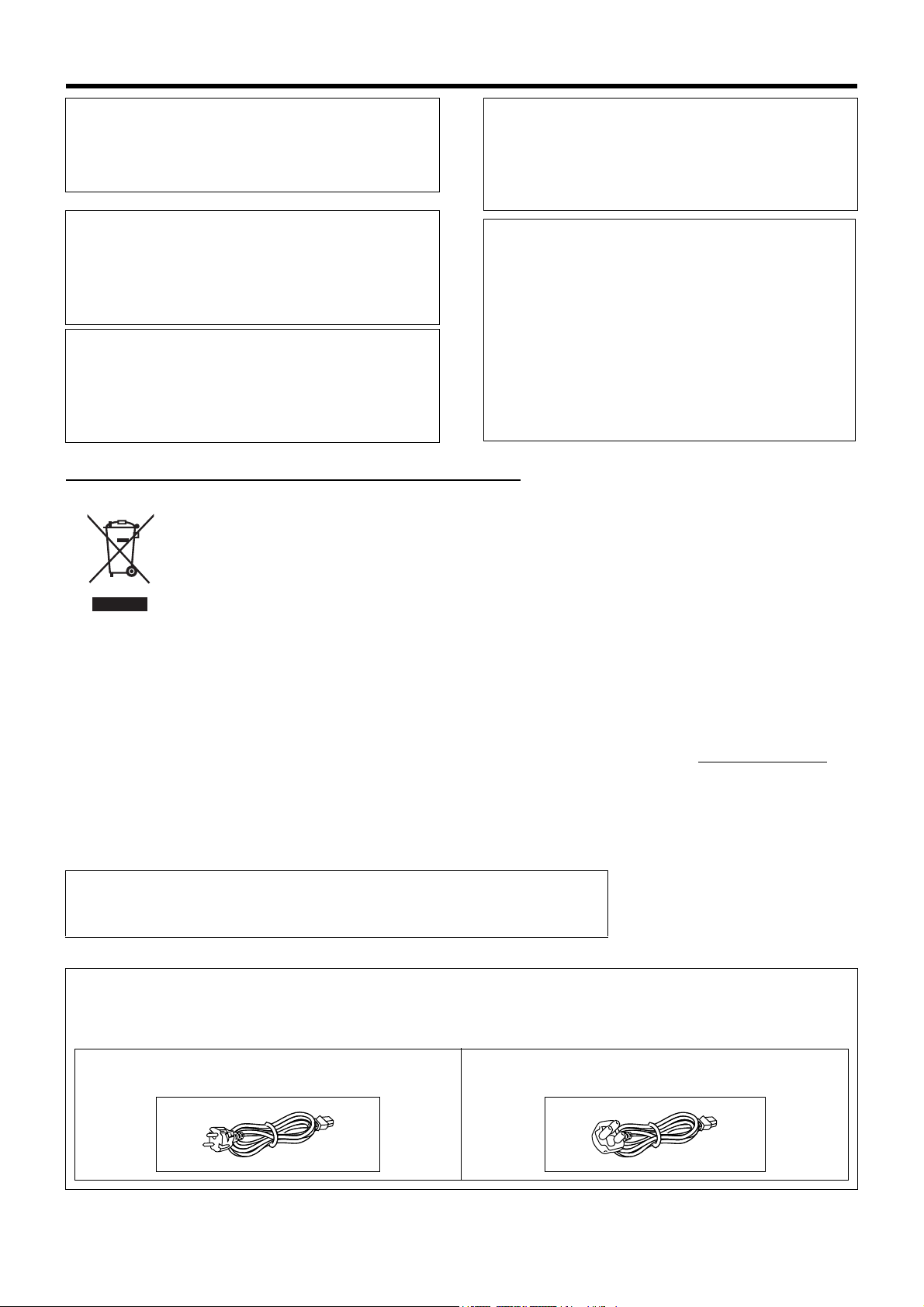
Caution for AC Power Cord
FOR YOUR SAFETY PLEASE READ THE FOLLOWING TEXT CAREFULLY.
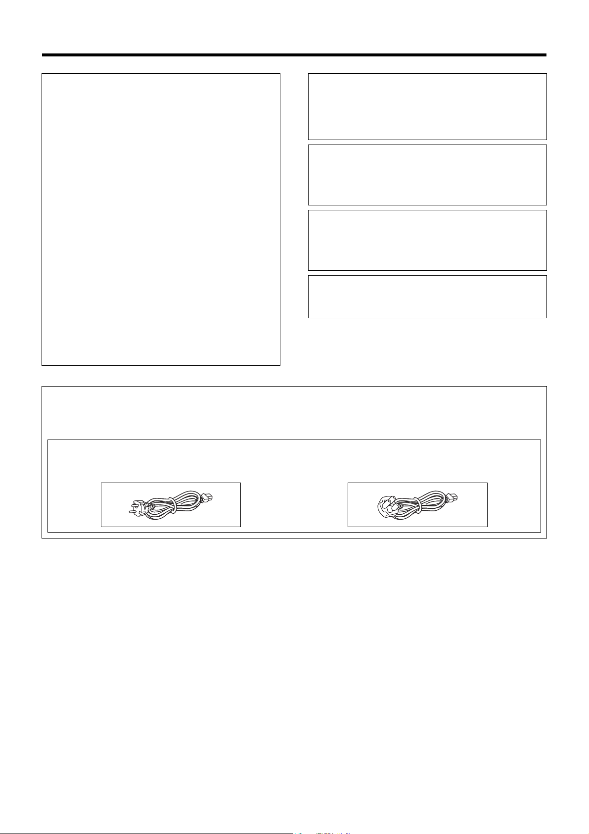
Appropriate AC Power Cord must be used in each local area.
FOR CONTINENTAL EUROPE, ETC.
Not to be used in the U.K.
FOR U.K. ONLY
If the plug supplied is not suitable for your socket outlet,
it should be cut off and appropriate one fitted.
III
Page 5
SAFETY PRECAUTIONS
WARNING
It should be noted that it may be unlawful to re-record
pre-recorded tapes, records, or discs without the consent
of the owner of copyright in the sound or video recording,
broadcast, or cable programme and in any literary,
dramatic, musical or artistic work embodied therein.
WARNING
This is a Class A product. In a domestic environment this
product may cause radio interference in which case the
user may be required to take adequate measures.
WARNING
CAUTION
RED colour indications on the operation panel are
provided but they are not safety related, RED colour
indications:
(1) HDD error indicator
(2) FAN error indicator
For PLUGGABLE EQUIPMENT, the socket outlet shall
be installed near the equipment and shall be easily
accessible.
Information for Users on Disposal of Old Equipment
[European Union]
This symbol indicates that the electrical and electronic equipment should not be disposed as general
household waste at its end-of-life. Instead, the product should be handed over to the applicable collection
point for the recycling of electrical and electronic equipment for proper treatment, recovery and recycling in
accordance with your national legislation.
By disposing of this product correctly, you will help to conserve natural resources and will help prevent
potential negative effects on the environment and human health which could otherwise be caused by
Attention:
This symbol is
only valid in the
European
Union.
inappropriate waste handling of this product. For more information about collection point and recycling of this
product, please contact your local municipal office, your household waste disposal service or the shop where
you purchased the product.
Penalties may be applicable for incorrect disposal of this waste, in accordance with national legislation.
(Business users)
If you wish to dispose of this product, please visit our web page www.jvc-europe.com
about the take-back of the product.
to obtain information
[Other Countries outside the European Union]
If you wish to dispose of this product, please do so in accordance with applicable national legislation or other
rules in your country for the treatment of old electrical and electronic equipment.
Dear Customer,
This apparatus is in conformance with the valid European
directives and standards regarding electromagnetic
compatibility and electrical safety.
European representatives of Victor Company of Japan
Limited is:
JVC Technology Centre Europe GmbH
P.O. Box 10 05 52
61145 Friedberg
Germany
E-1
Page 6

Getting Started
Main Features
This is an HDD External Unit for
Digital Video Recorders manufactured by JVC
This HDD unit can be connected to the following DVR
(Digital Video Recorders).
VR-509E
VR-N900U (scheduled for release December 2006)
* These units cannot be connected to any DVR or PC
manufactured by any other company.
* When the VR-509E is connected to the VR-D0U, you may
need a software update version for the DVR.
For more details, please contact the dealer where you
purchased the unit or your nearest JVC dealer.
Contents
Getting Started
Contents . . . . . . . . . . . . . . . . . . . . . . . . . . . . . . . . . . . . . . E-2
PRECAUTIONS . . . . . . . . . . . . . . . . . . . . . . . . . . . . . . . . E-3
Part Names and Functions . . . . . . . . . . . . . . . . . . . . . . . .E-4
Preparation
Attaching to the Rack . . . . . . . . . . . . . . . . . . . . . . . . . . . . E-5
Connecting the Digital Video Recorder. . . . . . . . . . . . . . . E-5
Others
Specifications . . . . . . . . . . . . . . . . . . . . . . . . . . . . . . . . . . E-6
How to Read this Manual
■ In the subsequent sections of this manual, this
equipment shall be referred to as VR-D0U.
■ The names of buttons used during operation
are enclosed in [ ].
Example: MENU button → [MENU]
* All product names stated in this manual are trademarks
or registered trademarks of their respective companies.
Marks such as™, ® and © are omitted in this manual.
E-2
Page 7

PRECAUTIONS
■ Place of storage and use
Please avoid storing or using this unit in the following
places:
• Extremely hot or cold places beyond the allowable
temperature for operation (5°C - 40°C).
• Humid or dry places beyond the allowable humidity
range for operation (30% - 80% RH).
• Dusty or sandy places.
• Places exposed to oil, smoke or steam, such as the
kitchen vicinity.
• Vibrating or unstable places.
• Places prone to condensation.
• Places that generates strong magnetic fields, e.g.,
transformer or motor.
• Places near devices that generate electric waves, e.g.,
transceiver or mobile phone.
• Places that generate radiation, X-rays or corrosive
gases.
■ Handling the unit
• Please do not place heavy objects on this unit, like a
monitor or TV. Also, do not stack the VR-D0U units on
top of each other.
• Please do not block the ventilation openings.
• Avoid violent shocks to the unit. Do not drop the unit.
■ Maintaining the unit (Please turn off the power
before performing maintenance work.)
Please wipe the unit with a soft cloth. Do not wipe it with
thinner or benzene lest the surface melts or becomes
dull. For stubborn stains, wipe first with a water-diluted
neutral detergent and then wipe dry.
■ Please use the supplied power cord. Using a
different type or damaged cord may cause fire
or electric shock.
■ To save energy, be sure to turn off the system
when not in use.
■ Do not use the power cord supplied with this
equipment on other devices.
■ Do not stack up the equipment to prevent
temperature within from rising.
■ Do not insert foreign object into this unit as this
may cause malfunction or electric shock.
Hard Disk Drive
The distance between the head and disk that read and write
data on the hard disk drive (hereinafter known as the HDD)
is a miniscule 0.02µm. Vibrations and physical shocks to the
HDD may therefore result in the head coming into contact
with the disk, producing dents and scratches to its surface.
This will consequently prevent data from being read, and will
result in disk crashes if use is continued. It is therefore
necessary to handle the recorder with great care.
■ The HDD is a consumable item. Replacement is
recommended after 10000 hours of use (if use in a 25°C
environment). For information on maintenance planning
and costs, consult your nearest JVC dealer.
■ It is recommended that an UPS (Uninterruptible Power
Supply) is used when installing additional external hard
disk drives to make sure the system remains stable.
■ If a power failure occurs during formatting of HDD,
disconnection, or when configuring or disabling mirroring,
operation of the equipment may be disabled even if it is
connected to the UPS.
■ Please note that we will not provide compensation for any
failure during recording or playback due to defects in this
equipment or the HDD.
■ Please note that recorded images will be erased when
replacing hard disks. Note that there are cases where
recorded images may be erased when software is
upgraded.
■ This equipment will automatically reset when minor data
writing errors occur with the HDD or other device in this
equipment’s system.
E-3
Page 8
Getting Started
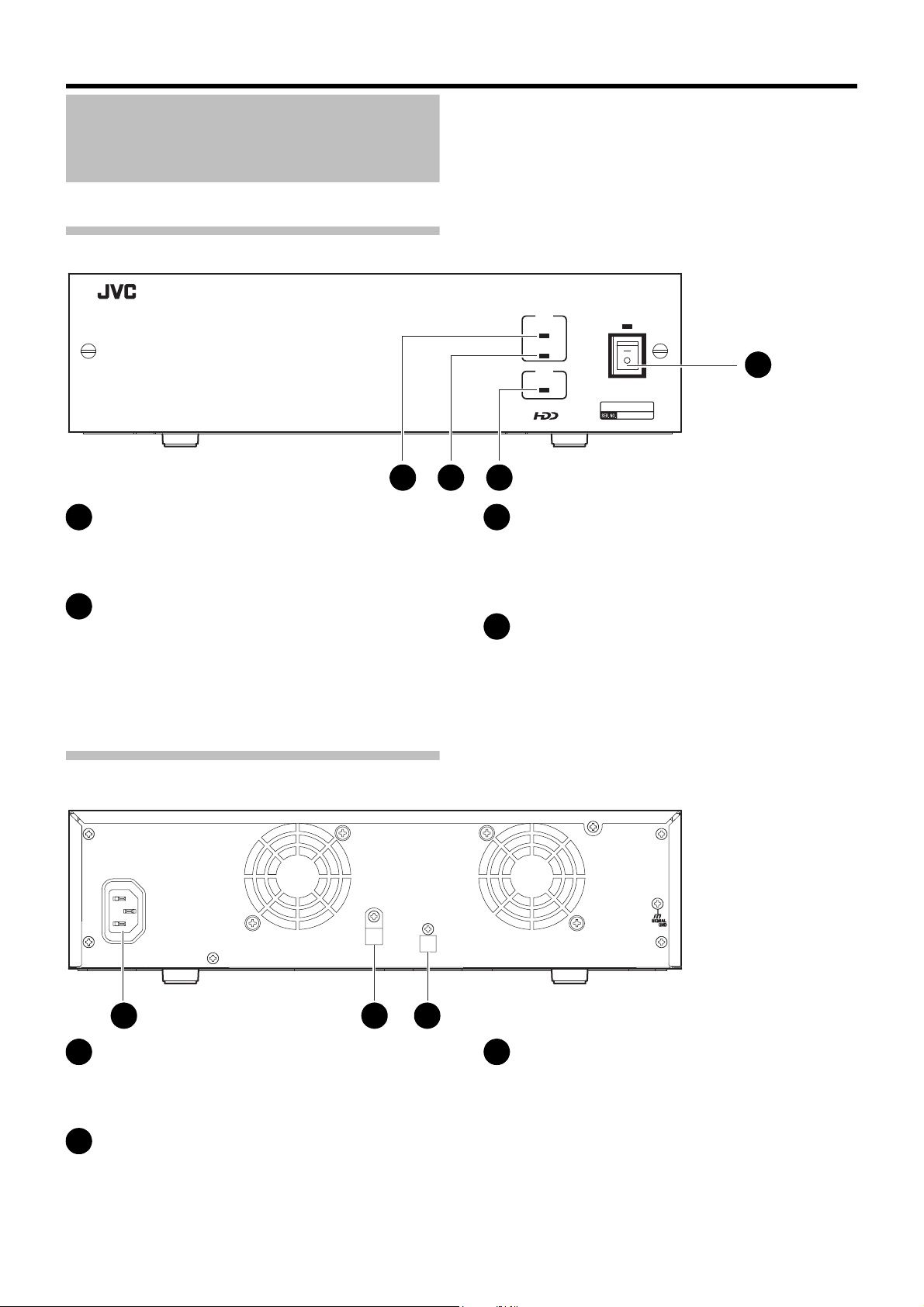
Part Names and Functions
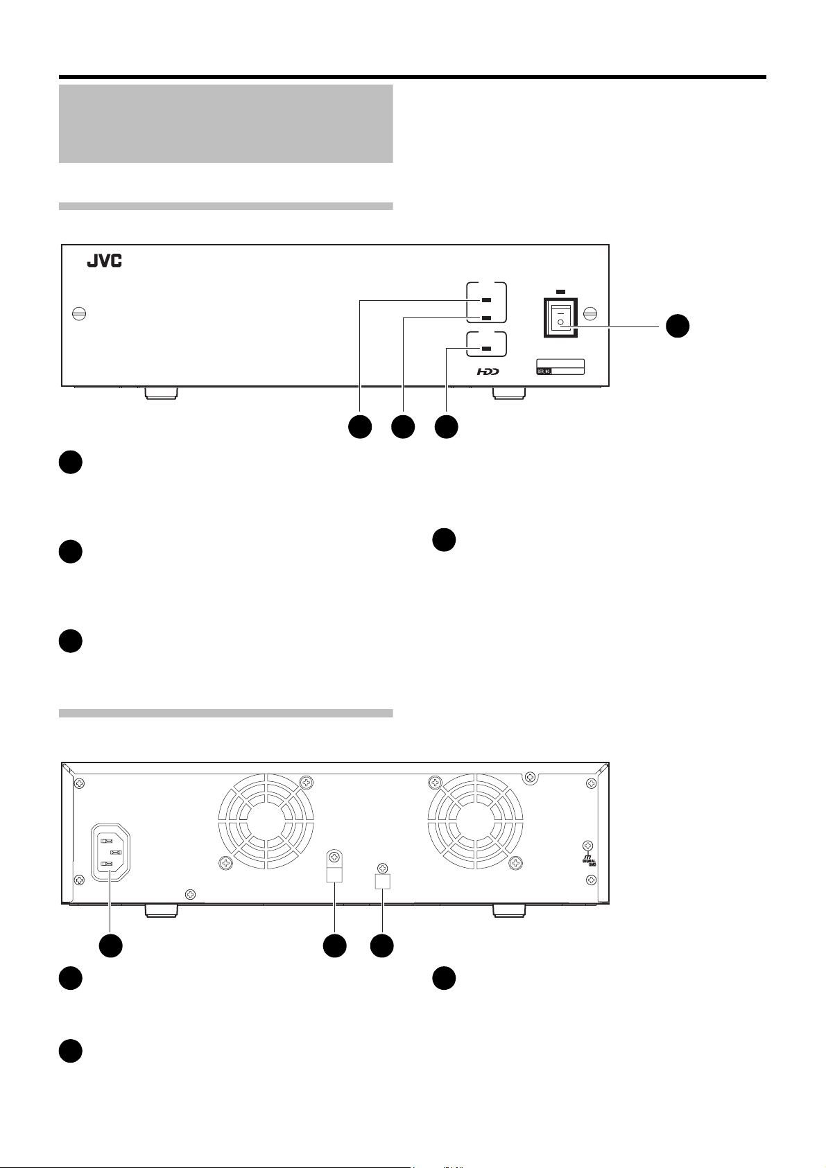
Front View
2 3 4
EXTERNAL HDD UNIT
HDD
ACCESS
ERR
FAN
ERR
OFF
POWER
ON
1
VR-D0U
[POWER] switch
1
Turns the power on and off. The POWER display lights
green after the power is switched on.
[HDD ACCESS] display
2
Lights green while the HDD is being accessed. Never
switch off the power while this display is lit.
Rear View
AC IN
TO RECORDER
[HDD ERR] display
3
Lights red if the HDD malfunctions. If this display lights
contact the vendor where your purchased the unit or a
JVC service representative for repairs.
[FAN ERR] display
4
Lights if the fan motor inside the unit malfunctions.
If this display lights contact the vendor where your
purchased the unit or a JVC service representative for
repairs.
5 76
[AC IN] Power input terminal
5
The connection point for the AC 120 V - 240 V power
cord provided with the unit.
Cable clamp
6
Prevents the connection cable from disconnecting.
☞Page E-5
E-4
[TO RECORDER] (DVR connection terminal)
7
The connection point for the provided cable and the
DVR. You must use the special cable provided for the
connection.
☞Page E-5
Page 9

Preparation
Attaching to the Rack
Use the rack mount fittings provided to attach the unit to the
EIA rack.
When installing this unit in the EIA rack, contact your
nearest JVC dealer.
Rack mount
fitting
1. Remove the unit side screws.
Remove the front panel side screws (×4).
2. Attach the rack mount fittings.
Use the four screws (M4 × 10 mm) at ➀ to fasten both
sides of the unit.
3. Remove the feet (×4) from the bottom of the
unit.
Loosen the fastening screws ➁ and remove them.
4. Attach the unit to the rack.
Use the provided four screws (M5 × 11 mm) at ➂ to
fasten.
Caution
• Never place anything on top of a unit with a rack mount
attached. This is to prevent unbalancing the rack, tipping it
over, falling, and damaging the unit.
• When installing two or more units in a rack, leave space
between the units about the size of one unit.
Connecting the Digital Video Recorder
Before connecting the DVR and this unit, make sure that
both are switched off.
For more details about the settings and operation of the
DVR to be connected to this unit, please refer to the DVR
operating instructions.
Cable clamp fastener screw
VR-D0U
AC IN
Digital video recorder
POWER
ON
OFF
AC IN 100V
1
2 3 4 5 7 89 10111213
1
2
1
2
VIDEO OUTAUDIO OUTAUDIO IN VGA OUT LAN SERIAL
3 4 5 7 8 9 10 11 12 13
SPOT OUT
To the serial terminal
VIDEO IN
6
6
THROUGH OUT
1
2
RS-232C
1. Connect this unit and DVR.
Use the provided cable to make the connection.
2. Fasten the connection cable.
Be sure to fasten the cable clamp (this prevents cable
disconnection).
➀ Loosen the fastener screw of the cable clamp, then
remove the cable clamp.
➁ Pass the connection cable through the cable clamp
then fasten it to the unit.
3. Connect the power cord.
Connect the power cord plug to an AC 120 V - 240 V
power outlet.
4. Switch this unit on.
5. Switch the DVR on.
Cable clamp
TO RECORDER
Connection cable (provided)
14 15 16
14 15 16
CLOCK RESET IN
CLOCK RESET OUT
ALARM RESET
REC OUT
COMMON
COMMON
WARNING OUT
EXT REC IN
OPE ON/OFF
SPOT 1
SPOT 2
RESERVE 1
COMMON
123
6789101112
1516COMMON
4
5
13
14
EMERGENCY
SIGNAL
ALARM IN
GND
RESERVE 2
6. Do the settings for the DVR.
Do the settings by following the procedures in the DVR
operating instructions.
Note
• Never switch off the unit while the HDD ACCESS display is lit.
• Always make sure that the DVR is switched off before you
switch on this power.
• Always power off the DVR before you switch off this unit.
(The HDD ACCESS display may stay lit for about 30
seconds after the DVR has been turned off. You may turn
off the power to the equipment because communication
has ended.)
E-5
Page 10
Others
Specifications
■ General
HDD Capacity 500 GB 1 TB 2 TB
Power Supply AC 120 V - 240 V, 50 Hz/60 Hz
Allowed Operation
Temperature Range
Allowed Storage
Temperature Range
Allowed Operation
Humidity Range
Weight 6.0 k
(13.2 lb)
Power Consumption
0.7 A (0.5 A)
5°C to 40°C
-20°C to 60°C
30% to 80%
g
(16.5 lb)
7.5 kg
8.0 kg
(17.6 lb)
0.7 A 0.7 A
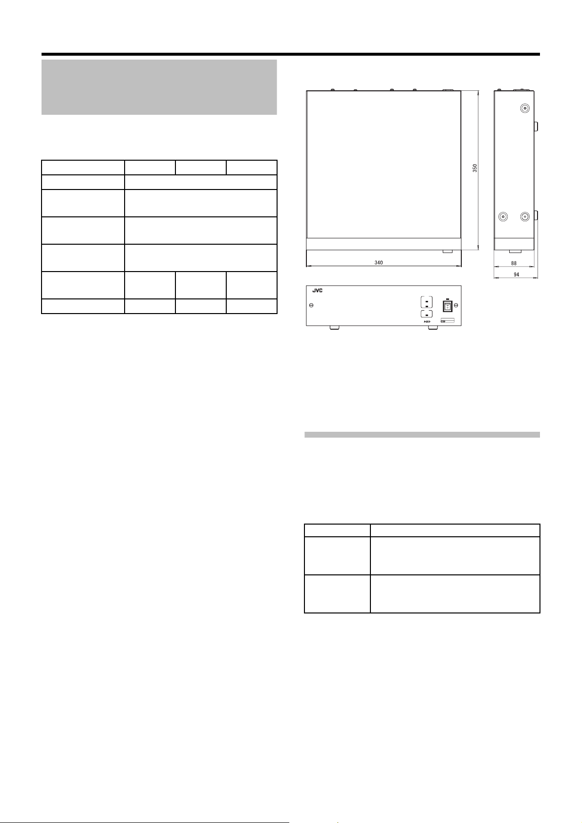
■ External Dimensions (Units: mm)
340 × 88 × 350 mm (W × H × D)
EXTERNAL HDD UNIT
HDD
ACCESS
ERR
FAN
ERR
POWER
ON
OFF
VR-D0U
■ Accessories
Instructions. . . . . . . . . . . . . . . . . . . . . . . . . . . . . . . . . . . .1
Power cord (For continental Europe, etc.: 2.5 m) . . . . . .2
Power cord (For U.K. only: 2 m) . . . . . . . . . . . . . . . . . . .1
Connection cable (1 m) . . . . . . . . . . . . . . . . . . . . . . . . . .1
Rack mount fitting . . . . . . . . . . . . . . . . . . . . . . . . . . . . . .2
Rack mount fitting fastener screws (M4 × 10 mm) . . . . .4
Rack mount screws (M5 × 11 mm) . . . . . . . . . . . . . . . . .4
Installation Date Label . . . . . . . . . . . . . . . . . . . . . . . . . .3
* Specifications and appearance of this unit are
subject to change for improvement without prior
notice.
Consumable Parts
The table below is a list of the consumable parts. The parts
fee that accompanies these replacement and repair costs
includes technical and official trip fees that are charged even
during the guarantee period.
Part name Remarks
Hard Disk Drive
(HDD)
Fan Unit The exchange period will expire after
The exchange period will expire after
10,000 hours of use (approx. one year)
from the beginning date of use.
30,000 hours of use (approx. three years)
from the beginning date of use.
E-6
In order to support exchange and maintenance of
consumable supplies, use the attached Installation date
label. Enter the beginning date of use on the Installation
date label and attach it to this equipment.
Page 11
SICHERHEITSVORKEHRUNGEN
SPANNUNGSVERSORGUNG
Anschluss am Netz
Die Betriebsspannung für dieses Gerät beträgt
AC120 V bis 240 V, 50 Hz/60 Hz
ACHTUNG:
UM DER GEFAHR VON BRÄNDEN UND
ELEKTRISCHEN SCHLÄGEN VORZUBEUGEN, DARF
DIESES GERÄT WEDER DEM REGEN NOCH HOHER
FEUCHTIGKEIT AUSGESETZT WERDEN.
ACHTUNG
Um elektrische Schläge zu vermeiden, das Gehäuse nie
öffnen. Im Innern befinden sich keine Teile, die vom
Benutzer gewartet werden können. Überlassen Sie die
Wartung qualifiziertem Service-Personal.
WARNUNG
Bei dem Gerät handelt es sich um ein Klasse-A-Produkt.
In Haushaltsumgebungen kann ein solches Produkt
Funkstörungen verursachen. In einem solchen Fall muss
der Benutzer geeignete Maßnahmen ergreifen.
Sehr geehrter Kunde, sehr geehrte Kundin,
dieses Gerät stimmt mit den gültigen europäischen
Richtlinien und Normen bezüglich
elektromagnetischer Verträglichkeit und elektrischer
Sicherheit überein.
Die europäische Vertretung für die Victor Company of
Japan, Limited ist:
JVC Technology Centre Europe GmbH
Postfach 10 05 52
61145 Friedberg
Deutschland
Benutzerinformationen zur Entsorgung alter Geräte
[Europäische Union]
Dieses Symbol zeigt an, dass das elektrische bzw. elektronische Gerät nicht als normaler Haushaltsabfall
entsorgt werden soll. Stattdessen sollte das Produkt zur fachgerechten Entsorgung, Weiterverwendung und
Wiederverwertung in Übereinstimmung mit der Landesgesetzgebung einer entsprechenden Sammelstelle für
das Recycling elektrischer und elektronischer Geräte zugeführt werden.
Die korrekte Entsorgung dieses Produkts dient dem Umweltschutz und verhindert mögliche Schäden für die
Umwelt und die menschliche Gesundheit, welche durch unsachgemäße Behandlung des Produkts auftreten
Hinweis:
Dieses Symbol
ist nur in der
Europäischen
Union gültig.
können. Weitere Informationen zu Sammelstellen und dem Recycling dieses Produkts erhalten Sie bei Ihrer
Gemeindeverwaltung, Ihrem örtlichen Entsorgungsunternehmen oder in dem Geschäft, in dem Sie das
Produkt gekauft haben.
Für die nicht fachgerechte Entsorgung dieses Abfalls können gemäß der Landesgesetzgebung Strafen
ausgesprochen werden.
(Geschäftskunden)
Wenn Sie dieses Produkt entsorgen möchten, besuchen Sie bitte unsere Webseite www.jvc-europe.com
Informationen zur Rücknahme des Produkts zu erhalten.
, um
[Andere Länder außerhalb der Europäischen Union]
Wenn Sie dieses Produkt entsorgen möchten, halten Sie sich dabei bitte an die entsprechenden
Landesgesetze und andere Regelungen in Ihrem Land zur Behandlung elektrischer und elektronischer Geräte.
Erklärung zum Rauschen (für die Bundesrepublik Deutschland):
Maschinenlärminformations-Verordunung 3. GPSGV, 06.01.2004: Der höchste
Schalldruckpegel beträgt 70 dB(A) oder weniger gemäß EN ISO 7779
Hinweis zum Netzanschlußkabel
Zu Ihrer Sicherheit lesen Sie bitte das folgende sorgfältig.
Verwenden Sie ausschließlich ein in Ihrem Land zulässiges Netzkabel.
Für Kontinentaleuropa
Nicht für den Gebrauch in Großbritannien.
Nur für Großbritannien
G-1
Page 12

Einleitung
Hauptmerkmale
Dieses Gerät ist ein externes
Festplattenlaufwerk für digitale
Videorekorder, die von JVC
hergestellt wurden.
Dieses Festplattenlaufwerk kann an die folgenden digitalen
Videorekorder (DVR) angeschlossen werden.
VR-509E
VR-N900U (geplante Markteinführung: Dezember 2006)
* Diese Geräte können nicht an digitale Videorekorder oder
PCs von anderen Firmen angeschlossen werden.
* Wenn das Modell VR-509E an das Modell VR-D0U
angeschlossen wird, müssen Sie die Software-Version des
digitalen Videorekorders aktualisieren.
Weitere Einzelheiten erhalten Sie im Geschäft, in dem Sie
Ihr Gerät gekauft haben, oder bei Ihrem nächsten JVC-
Fachhändler.
Inhalt
Einleitung
Inhalt. . . . . . . . . . . . . . . . . . . . . . . . . . . . . . . . . . . . . . . . .G-2
VORSICHTSHINWEISE. . . . . . . . . . . . . . . . . . . . . . . . . .G-3
Bezeichnungen und Funktionen der Teile . . . . . . . . . . . . . . G-4
Vorbereitung
Befestigung am Rack . . . . . . . . . . . . . . . . . . . . . . . . . . . .G-5
Anschließen des digitalen Videorekorders . . . . . . . . . . . .G-5
Sonstiges
Technische Daten . . . . . . . . . . . . . . . . . . . . . . . . . . . . . . .G-6
Wie diese Bedienungsanleitung zu lesen ist
■ In den nachfolgenden Abschnitten dieser
Bedienungsanleitung wird dieses Gerät als VRD0U bezeichnet.
■ Die Bezeichnungen der Tasten, die bei der
Bedienung verwendet werden, sind in eckigen
Klammern ([ ]) angeführt.
Beispiel: Menü-Taste → [MENU]
* Alle in der Bedienungsanleitung angeführten
Produktnamen sind Warenzeichen oder eingetragene
Warenzeichen der jeweiligen Firmen.
Bezeichnungen wie™, ® und © werden in dieser
Bedienungsanleitung ausgelassen.
G-2
Page 13

VORSICHTSHINWEISE
Führen Sie keine Fremdkörper in das Gerät ein, da
■
anderenfalls die Gefahr einer Funktionsstörung
bzw. eines Stromschlags besteht.
■ Aufbewahrungs- und Verwendungsorte
Vermeiden Sie die folgenden Orte, um das Gerät
aufzubewahren oder zu verwenden:
• Besonders heiße oder kalte Orte, deren Temperatur
außerhalb des zulässigen Temperaturbereichs von 5°C
bis 40°C liegt.
• Feuchte oder trockene Orte, deren Luftfeuchtigkeit
außerhalb des zulässigen Bereichs von 30% bis 80%
relative Feuchte liegt.
• Staubige oder sandige Orte.
• Orte mit viel Öl, Rauch oder Dampf, beispielsweise die
Umgebung einer Küche.
• Orte, die Erschütterungen ausgesetzt oder unstabil sind.
• Orte, an denen sich leicht Kondensation bilden kann.
• Orte, die starke Magnetfelder erzeugen, z. B. die
Umgebung von Transformatoren oder Motoren.
• Orte in der Umgebung von Geräten, die starke
Elektrowellen erzeugen, z. B. Transceiver oder Handys.
• Orte, die Strahlungen, Röntgenstrahlen oder korrosive
Gase erzeugen.
■ Handhabung des Geräts
• Stellen Sie keine schweren Gegenstände,
beispielsweise einen Bildschirm oder Fernsehen, auf
dieses Gerät. Stapeln Sie auch nicht mehrere VRD0U-Modelle übereinander.
• Blockieren Sie nicht die Entlüftungsöffnungen.
• Setzen Sie das Gerät keinen starken Stößen aus.
Lassen Sie das Gerät nicht fallen.
■
Wartung des Geräts (Schalten Sie die
Stromversorgung aus, bevor Sie Wartungsarbeiten
durchführen.)
Wischen Sie das Gerät mit einem weichen Tuch ab.
Wischen Sie es nicht mit Verdünner oder Benzol ab, da
anderenfalls die Gehäuseoberfläche beschädigt oder
matt werden kann. Bei hartnäckigen Flecken wischen Sie
das Gerät zuerst mit einem Tuch ab, das in einem
neutralen Reinigungsmittel angefeuchtet wurde, und
wischen Sie das Gerät dann trocken.
■ Bitte verwenden Sie das mitgelieferte
Netzkabel. Bei Verwendung eines anderen bzw.
eines beschädigten Netzkabels besteht Brandoder Stromschlaggefahr.
■ Um Strom zu sparen, schalten Sie das Gerät
aus, wenn Sie es nicht verwenden.
■ Verwenden Sie das Netzkabel dieses Geräts
nicht für andere Geräte.
■ Stapeln Sie dieses Gerät nicht, damit im
Geräteinneren kein Temperaturstau auftritt.
Festplattenlaufwerk
Der Abstand zwischen dem Kopf und der Platte, die die
Daten lesen und auf dem Festplattenlaufwerk (HDD)
aufzeichnen, beträgt nur 0,02 µm. Erschütterungen und
Stöße, denen das Festplattenlaufwerk ausgesetzt ist,
können dazu führen, dass der Kopf mit der Platte in
Berührung kommt, so dass auf ihrer Oberfläche Beulen oder
Kratzer entstehen. Dies kann dazu führen, dass beim Lesen
der Daten Probleme auftreten, so dass die Platte abstürzt,
falls der Betrieb fortgesetzt wird. Daher sollten Sie beim
Umgang mit dem Rekorder besonders vorsichtig sein.
■ Das Festplattenlaufwerk ist ein Verbrauchsteil. Wir
empfehlen, das Festplattenlaufwerk nach jeweils 10 000
Betriebsstunden (in einer Umgebungstemperatur von
25°C) auszutauschen. Weitere Informationen zur Planung
der Wartung und deren Kosten erhalten Sie bei Ihrem
nächsten JVC-Fachhändler.
■ Wir empfehlen, eine unterbrechungsfreie
Stromversorgung (USV) zu verwenden, wenn Sie
zusätzliche externe Festplattenlaufwerke anschließen,
damit die Anlage stabil bleibt.
■ Falls beim Formatieren des Festplattenlaufwerks, seiner
Abtrennung oder Konfiguration bzw. der Deaktivierung
des Plattenspiegelungsbetriebs ein Stromausfall auftritt,
kann der Betrieb des Geräts beeinträchtigt werden, selbst
wenn es an eine unterbrechungsfreie Stromversorgung
angeschlossen ist.
■ Beachten Sie bitte, dass wir keinen Schadenersatz für
Geräteversagen während der Aufnahme oder
Wiedergabe anbieten, die auf Defekte in diesem Gerät
oder dem Festplattenlaufwerk zurückzuführen sind.
■ Beachten Sie bitte, dass die aufgezeichneten Bilder beim
Austauschen von Festplatten gelöscht werden. Beachten
Sie bitte, dass die aufgezeichneten Bilder u. U. auch
beim Aktualisieren der Software gelöscht werden können.
■ Dieses Gerät führt automatisch eine Rücksetzung durch,
wenn kleinere Datenschreibfehler auf der Festplatte oder
anderen Geräten dieser Anlage auftreten.
G-3
Page 14
Einleitung
Bezeichnungen und Funktionen der Teile
Frontansicht
2 3 4
EXTERNAL HDD UNIT
HDD
ACCESS
ERR
FAN
ERR
OFF
POWER
ON
1
VR-D0U
Netzschalter [POWER]
1
Dient zum Ein- und Ausschalten des Geräts. Die
Anzeige POWER leuchtet grün, nachdem das Gerät
eingeschaltet wurde.
Anzeige [HDD ACCESS]
2
Leuchtet grün, wenn ein Zugriff auf das
Festplattenlaufwerk erfolgt. Schalten Sie das Gerät nie
aus, während diese Anzeige leuchtet.
Anzeige [HDD ERR]
3
Leuchtet rot, wenn eine Funktionsstörung des
Festplattenlaufwerks vorliegt.
Rückansicht
AC IN
Falls diese Anzeige leuchtet, wenden Sie sich an das
Geschäft, in dem Sie das Gerät erworben haben, oder
eine JVC-Kundendienststelle, um das Gerät reparieren
zu lassen.
Anzeige [FAN ERROR]
4
Leuchtet, wenn eine Funktionsstörung des
Gebläsemotors im Gerät vorliegt.
Falls diese Anzeige leuchtet, wenden Sie sich an das
Geschäft, in dem Sie das Gerät erworben haben, oder
eine JVC-Kundendienststelle, um das Gerät reparieren
zu lassen.
5 76
Stromeingangsbuchse [AC IN]
5
Schließen Sie das mit diesem Gerät mitgelieferte Kabel für
Netzstrom mit einer Spannung von 120 V bis 240 V hier an.
Kabelklemme
6
Verhindert, dass das Anschlusskabel abgetrennt wird.
☞Seite G-5
G-4
TO RECORDER
[TO RECORDER] (DVR-Anschlussbuchse)
7
Verwenden Sie das mit diesem Gerät mitgelieferte
Kabel, um den digitalen Videorekorder an diese
Buchse anzuschließen. Sie müssen das für den
Anschluss vorgesehene Spezialkabel verwenden.
☞Seite G-5
Page 15

Vorbereitung
V
Befestigung am Rack
Verwenden Sie die mitgelieferten Rack-Montageanschlussstücke, um das Gerät am EIA-Rack zu befestigen.
Wenden Sie sich an den nächsten JVC-Fachhändler, um
das Gerät am EIA-Rack zu befestigen.
Rack-Montage-
anschlussstücke
1. Entfernen Sie die Seitenschrauben des Geräts.
Entfernen Sie die Seitenschrauben der Frontplatte (x4).
2. Befestigen Sie die Rack-Montageanschlussstücke.
Verwenden Sie die vier Schrauben (M4 x 10 mm) von
Schritt ➀, um beide Seiten des Geräts zu befestigen.
3. Entfernen Sie die Füße (x4) von der Unterseite
des Geräts.
Lockern Sie die Befestigungsschrauben ➁, und
entfernen Sie sie dann.
4. Befestigen Sie das Gerät am Rack.
Verwenden Sie die vier Schrauben (M5 x 11 mm) von
➂, um das Gerät zu befestigen.
Schritt
orsicht
• Stellen Sie nie Gegenstände auf ein Gerät mit
angebrachten Rack-Montageanschlussstücken. Sie
verhindern dadurch, dass das Rack nicht das
Gleichgewicht verliert, umfällt und das Gerät beschädigt.
• Achten Sie bei der Installation von zwei oder mehreren
Geräten in einem Rack darauf, dass zwischen den
Geräten ausreichend Platz bleibt, und zwar jeweils
entsprechend etwa der Größe eines Geräts.
Anschließen des digitalen Videorekorders
Bevor Sie den digitalen Videorekorder mit dem Hauptgerät
verbinden, vergewissern Sie sich, dass beide Geräte
ausgeschaltet sind.
Weitere Einzelheiten zu den Einstellungen und der
Bedienung des digitalen Videorekorders, der an dieses
Gerät angeschlossen werden soll, entnehmen Sie bitte der
Bedienungsanleitung des digitalen Videorekorders.
Kabelklemmen-
VR-D0U
AC IN
Digitaler Videorekorder
POWER
ON
OFF
AC IN 100V
1
2 3 4 5 7 89 10111213
1
2
3 4 5 7 8 9 10 11 12 13
SPOT OUT
1
2
VIDEO OUTAUDIO OUTAUDIO IN VGA OUT LAN SERIAL
An die serielle Schnittstelle
VIDEO IN
6
6
THROUGH OUT
1
2
RS-232C
1. Verbinden Sie dieses Gerät mit dem digitalen
Videorekorder.
Verwenden Sie das für den Anschluss vorgesehene
Spezialkabel.
2. Befestigen Sie das Anschlusskabel.
Befestigen Sie die Kabelklemme (dadurch wird
verhindert, dass das Kabel abgetrennt wird).
➀ Locken Sie die Befestigungsschraube des
Kabelklemme, und nehmen Sie die Kabelklemme
dann ab.
➁ Führen Sie das Anschlusskabel durch die Kabelklemme
ein, und befestigen Sie es dann am Gerät.
3. Schließen Sie das Netzkabel an.
Stecken Sie den Netzkabelstecker in eine Steckdose,
die Strom mit einer Spannung von 120 V bis 240 V führt.
4. Schalten Sie dieses Gerät ein.
5. Schalten Sie den digitalen Videorekorder ein.
6. Führen Sie die Einstellungen des digitalen
Videorekorders durch.
Führen Sie diese Einstellungen durch, indem Sie die
Verfahren in der Bedienungsanleitung des digitalen
Videorekorders befolgen.
Hinweise
• Schalten Sie das Gerät nie aus, während die Anzeige [HDD
ACCESS] leuchtet.
• Vergewissern Sie sich immer, dass der digitale Videorekorder
ausgeschaltet ist, bevor Sie dieses Gerät einschalten.
• Schalten Sie immer zuerst den digitalen Videorekorder aus, bevor
Sie dieses Gerät ausschalten. (Die Anzeige [HDD ACCESS]
bleibt ca. 30 Sekunden lang leuchten, nachdem der digitale
Videorekorder ausgeschaltet wurde. Sie können das Gerät dann
ausschalten, da die Kommunikation beendet wurde.)
Befestigungsschraube
Kabelklemme
TO RECORDER
Anschlusskabel (mitgeliefert)
14 15 16
14 15 16
CLOCK RESET IN
CLOCK RESET OUT
ALARM RESET
REC OUT
COMMON
COMMON
WARNING OUT
EXT REC IN
OPE ON/OFF
SPOT 1
SPOT 2
RESERVE 1
123
6789101112
4
5
SIGNAL
ALARM IN
GND
RESERVE 2
1516COMMON
COMMON
13
14
EMERGENCY
G-5
Page 16

Sonstiges
Technische Daten
■ Allgemein
■ Außenabmessungen (Einheit: mm)
340 x 88 x 350 mm (B x H x T)
Festplattenspeicherkapazität
Stromversorgung
Netzstrom
500 GB 1 TB 2 TB
120 V bis 240 V, 50 Hz/60 Hz
Zulässige
Betriebs-
5°C bis 40°C
temperatur
Zulässige
Lagerungs-
-20°C bis 60°C
temperatur
Zulässige
Betriebsfeuchtig-
30% bis 80%
keit
Gewicht 6,0 k
Leistungs-
aufnahme
0,7 A (0,5 A) 0,7 A 0,7 A
g 7,5 kg 8,0 kg
■ Zubehör
Bedienungsanleitung . . . . . . . . . . . . . . . . . . . . . . . . . . .1
Netzkabel (Für Kontinentaleuropa usw.: 2,5 m). . . . . . . . 2
Netzkabel (nur für Großbritannien: 2 m) . . . . . . . . . . . . .1
Anschlusskabel (1 m) . . . . . . . . . . . . . . . . . . . . . . . . . . .1
Rack-Montageanschlussstück . . . . . . . . . . . . . . . . . . . .2
Befestigungsschrauben (M4 x 10 mm) für die
Rack-Montageanschlussstücke . . . . . . . . . . . . . . . . . . . .4
Rack-Montageschrauben (M5 x 11 mm) . . . . . . . . . . . . . 4
Installationsdatumsaufkleber . . . . . . . . . . . . . . . . . . . . . .3
EXTERNAL HDD UNIT
HDD
POWER
ACCESS
ON
ERR
OFF
FAN
ERR
VR-D0U
* Änderungen der technischen Daten und der äußere
Aufmachung des Geräts jederzeit ohne vorherige
Ankündigung vorbehalten.
Verbrauchsteile
Die untenstehende Tabelle zeigt eine Liste der
Verbrauchsteile. Die neben den Ersatzteilen aufgelisteten
Preise umfassen die technischen Kosten und die
Versandkosten, die selbst während der Garantieperiode
berechnet werden.
G-6
Teilbezeichnung Anmerkungen
Festplattenlaufwerk
(HDD)
Die Austauschperiode geht nach
10 000 Betriebsstunden (ungefähr ein
Jahr) ab dem Datum des
Gebrauchsbeginns zu Ende.
Gebläseeinheit Die Austauschperiode geht nach
30 000 Betriebsstunden (ungefähr
drei Jahre) ab dem Datum des
Gebrauchsbeginns zu Ende.
Um den Austausch und die Wartung der Verbrauchsteile zu
unterstützen, verwenden Sie den angebrachten
Installationsdatumsaufkleber. Geben Sie das Anfangsdatum
des Gebrauchs auf dem Installationsdatumsaufkleber ein,
und befestigen Sie den Aufkleber an diesem Gerät.
Page 17

PRÈCAUTIONS DE SÈCURITÈ
Cher(e) client(e),
Cet appareil est conforme aux directives et normes européennes en vigueur concernant
la compatibilité électromagnétique et à la sécurité électrique.
Représentant européen de la société Victor Company of Japan, Limited :
JVC Technology Centre Europe GmbH
Postfach 10 05 52
61145 Friedberg
Allemagne
Informations relatives à l’élimination des appareils usagés, à l’fintention des utilisateurs
[Union européenne]
Lorsque ce symbole figure sur un appareil électrique et électronique, cela signifie qu’il ne doit pas être
éliminé en tant que déchet ménager à la fin de son cycle de vie. Le produit doit être porté au point de précollecte approprié au recyclage des appareils électriques et électroniques pour y subir un traitement, une
récupération et un recyclage, conformément à la législation nationale.
En éliminant correctement ce produit, vous contriburez à la conservation des ressources naturelles et à la
Attention :
Ce symbole
n’est reconnu
que dans
l’Union
européenne.
prévention des éventuels effets négatifs sur l’environnement et la santé humaine, pouvant être dus à la
manipulation inappropriée des déchets de ce produit. Pour plus d’informations sur le point de pré-collecte et
le recyclage de ce produit, contactez votre mairie, le service d’évacuation des ordures ménagères ou le
magasin dans lequel vous avez acheté le produit.
Des amendes peuvent être infligées en cas d’élimination incorrecte de ce produit, conformément à la
législation nationale.
(Utilisateurs professionnels)
Si vous souhaitez éliminer ce produit, visitez notre page Web www.jvc-europe.com
informations sur sa récupération.
afin d’obtenir des
[Pays ne faisant pas partie de l’Union européenne]
Si vous souhaitez éliminer ce produit, faites-le conformément à la législation nationale ou autres règles en
vigueur dans votre pays pour le traitement des appareils électriques et électroniques usagés.
F-1
Page 18

Pour commencer
Principales caractéristiques
Cet appareil est une Unité HDD
Externe prévue pour les
enregistreurs vidéo numériques
fabriqués par JVC
Cette unité HDD peut être connectée aux enregistreurs
vidéo numériques (DVR) indiqués ci-dessous.
VR-509E
VR-N900U (lancement prévu pour Décembre 2006)
* Cet appareil ne peut pas être connecté à un DVR ou PC
d’une autre marque.
* Quand le VR-509E est connecté au VR-D0U, une version
mise à jour du logiciel peut s’avérer nécessaire pour le DVR.
Pour plus de détails, prière de contacter le revendeur chez
qui on a acheté l’appareil ou le revendeur JVC le plus
proche.
Sommaire
Pour commencer
Sommaire . . . . . . . . . . . . . . . . . . . . . . . . . . . . . . . . . . . . . F-2
PRÉCAUTIONS . . . . . . . . . . . . . . . . . . . . . . . . . . . . . . . . F-3
Nomenclature et fonctions . . . . . . . . . . . . . . . . . . . . . . . . F-4
Préparation
Fixation à un bâti . . . . . . . . . . . . . . . . . . . . . . . . . . . . . . . F-5
Connexion de l’enregistreur vidéo numérique . . . . . . . . . F-5
Divers
Caractéristiques techniques . . . . . . . . . . . . . . . . . . . . . . . F-6
Comment lire ce manue
■ Dans la suite de ce manuel, ce matériel est
appelé VR-D0U.
■ Les noms des touches utilisées pour les
diverses opérations sont indiqués entre [ ].
Exemple: Touche MENU → [MENU]
* Tous les noms de produit mentionnés dans ce manuel
sont des marques de fabrique ou des marques déposées
de leurs sociétés respectives.
Dans ce manuel, les marques telles que™, ® et © sont
omises.
F-2
Page 19

PRÉCAUTIONS
■ Endroit de rangement et d’utilisation
Prière d’éviter de ranger ou d’utiliser cet appareil dans les
endroits suivants:
• Endroits extrêmement froids ou chauds où la
température est hors de la plage d’utilisation
admissible (5°C - 40°C).
• Endroits humides ou secs où l’h’umidité relative est
hors de la plage d’utilisation admissible (30% 80% HR).
• Endroits poussiéreux ou sablonneux.
• Endroits exposés à de l’huile, de la fumée ou de la
vapeur, comme dans une cuisine ou à proximité.
• Endroits instables ou soumis à des vibrations.
• Endroits sujets à de la condensation.
• Endroits qui génèrent de puissants champs
magnétiques, par ex., transformateur ou moteur
électrique.
• Endroits à proximité d’appareils qui génèrent des
ondes électromagnétiques, par ex., émetteur-récepteur
ou téléphone portable.
• Endroits où des radiations, des rayons X ou des gaz
corrosifs sont générés.
■ Manipulation de l’appareil
• Prière de ne pas poser d’objet lourd, tel qu’un moniteur
ou un téléviseur, sur cet appareil. En outre, ne pas
empiler plusieurs appareils VR-D0U.
• Prière de ne pas obstruer les ouvertures de ventilation.
• Eviter de soumettre l’appareil à des chocs. Ne pas le
laisser tomber.
■ Entretien de l’appareil (Prière de couper
l’alimentation avant de procéder à toute
opération d’entretien.)
Prière d’essuyer l’appareil avec un chiffon doux. Ne jamais
utiliser du diluant ou du benzène pour le nettoyer; cela
pourrait faire fondre ou ternir la surface. Pour les taches
rebelles, essuyer d’abord avec un chiffon légèrement
imbibé d’un détergent neutre dilué à l’eau, puis avec un
chiffon sec.
■ Prière d’utiliser le cordon d’alimentation fourni.
L’utilistion d’un cordon endommagé ou de type
différent peut donner lieu à un incendie ou un
choc électrique.
■ Pour économiser l’énergie, ne pas oublier
d’éteindre le système quand il n’est pas utilisé.
■ Ne pas utiliser le cordon d’alimentation fourni
avec cet appareil sur un autre matériel.
■ Pour éviter toute augmentation anormale de la
température interne des divers appareils, ne
pas les empiler.
■ Ne pas introduire de corps étranger dans cet
appareil; cela pourrait entraîner un mauvais
fonctionnement ou un choc électrique.
Disque dur
Le minuscule espace entre le disque dur (aussi appelé
HDD) et la tête qui lit et écrit les données sur ce disque est
de 0,02 µm. Si le disque dur est soumis à des vibrations ou
des chocs, cela peut entraîner un contact de la tête avec le
disque, donnant lieu à des entailles et des rayures sur la
surface de celui-ci. Ceci empêche alors la lecture des
données, et peut provoquer un endommagement
irrémédiable du disque. Il est donc nécessaire de manipuler
l’enregistreur avec une très grande attention.
■ Le disque dur est un élément consommable. Il est
conseillé de le remplacer après 10 000 heures
d’utilisation (sous une température ambiante de 25°C).
Pour les informations concernant les prévisions et les
frais d’entretien, consulter le revendeur JVC le plus
proche.
■ Il est conseillé d’utiliser une alimentation ininterruptible
(UPS) lors de l’installation de disques durs externes
supplémentaires, cela permettra d’assurer la stabilité du
système.
■ Si une panne d’alimentation se produit pendant le
formatage du disque dur, la déconnexion, ou lors de la
configuration ou de la désactivation du mode miroir, le
fonctionnement du matériel peut être interrompu même
s’il est connecté à une UPS.
■ Prière de noter que nous n’accordons aucune
indemnisation pour toute panne pendant l’enregistrement
ou la lecture du fait de défauts dans ce matériel ou le
disque dur.
■ Prière de noter que les images enregistrées seront
effacées lors du remplacement des disques durs. Noter
que dans certains cas les images enregistrées peuvent
être effacées lors de la mise à niveau du logiciel.
■ Ce matériel est automatiquement réinitialisé quand des
erreurs mineures d’écriture de données se produisent
avec le disque dur ou tout autre appareil se trouvant dans
le système.
F-3
Page 20

Pour commencer
Nomenclature et fonctions
Vue de face
2 3 4
EXTERNAL HDD UNIT
HDD
ACCESS
ERR
FAN
ERR
OFF
POWER
ON
1
VR-D0U
Interrupteur [POWER]
1
Permet d’allumer et d’éteindre l’appareil. L’affichage
POWER s’allume en vert quand l’appareil est allumé.
Affichage [HDD ACCESS]
2
S’allume en vert quand il y a un accès au disque dur.
Ne jamais éteindre l’appareil quand cet affichage est
allumé.
Vue de dos
AC IN
TO RECORDER
Affichage [HDD ERR]
3
S’allume en rouge en cas de mauvais fonctionnement
du disque dur. Si cet affichage s’allume, contacter le
revendeur chez qui on a acheté l’appareil ou un agent
de service JVC pour le faire réparer.
Affichage [FAN ERR]
4
S’allume en cas de mauvais fonctionnement du moteur de
ventilateur situé à l’intérieur de l’appareil. Si cet affichage
s’allume, contacter le revendeur chez qui on a acheté
l’appareil ou un agent de service JVC pour le faire réparer.
5 76
Borne d’entrée d’alimentation [AC IN]
5
Point de connexion pour le cordon d’alimentation CA
120 V - 240 V fourni avec l’appareil.
Bride de câble
6
Empêche le câble de connexion de se débrancher.
☞Page F-5
F-4
[TO RECORDER] (Borne de connexion de
7
DVR)
Point de connexion pour le câble fourni et le DVR. Pour
la connexion, il faut utiliser le câble spécial fourni.
☞Page F-5
Page 21

Préparation
Fixation à un bâti
Pour fixer l’appareil à un bâti EIA, utiliser les ferrures de
fixation fournies.
Pour l’installation de cet appareil dans un bâti EIA, contacter
le revendeur JVC le plus proche.
Ferrure de
fixation sur
bâti
1. Enlever les vis latérales de l’appareil.
Enlever les vis latérales du panneau avant (×4).
2. Monter les ferrures de fixation sur bâti.
Utiliser les quatre vis (M4 × 10 mm) en ➀ pour fixer les
deux côtés de l’appareil.
3. Enlever les pieds (×4) de la base de l’appareil.
Desserrer les vis de fixation ➁ et les enlever.
4. Fixer l’appareil au bâti.
Utiliser les quatre vis fournies (M5 × 11 mm) en ➂ pour
fixer.
Attention
• Ne jamais rien poser sur un appareil fixé à un bâti. Le bâti
pourrait être déséquilibré, se renverser, tomber, et
endommager l’appareil.
• Lors de l’installation de deux appareils ou plus dans un
bâti, laisser un espace d’environ la taille d’un appareil
entre eux.
Connexion de l’enregistreur vidéo numérique
Avant de connecter le DVR et l’appareil, s’assurer que les
deux sont éteints.
Pour plus de détails sur les réglages et l’utilisation du DVR à
connecter à cet appareil, prière de se référer au mode
d’emploi du DVR.
Vis de fixation de bride
VR-D0U
AC IN
Enregistreur vidéo numérique
POWER
ON
OFF
AC IN 100V
1
2 3 4 5 7 89 10111213
1
2
3 4 5 7 8 9 10 11 12 13
SPOT OUT
1
2
VIDEO OUTAUDIO OUTAUDIO IN VGA OUT LAN SERIAL
A la borne série
VIDEO IN
6
6
THROUGH OUT
1
2
RS-232C
1. Connecter cet appareil et le DVR.
Utiliser le câble fourni pour faire la connexion.
2. Attacher le câble de connexion.
Veiller à fixer la bride de câble (cela empêche la
déconnexion du câble).
➀ Desserrer la vis de fixation de la bride de câble, puis
enlever la bride de câble.
➁ Faire passer le câble de connexion à travers la bride
de câble puis fixer cette bride à l’appareil.
3. Brancher le cordon d’alimentation.
Brancher le cordon d’alimentation à une prise CA 120 V
- 240 V.
4. Allumer cet appareil.
5. Allumer le DVR.
6. Faire les réglages pour le DVR.
Faire les réglages en procédant comme décrit dans le
mode d’emploi du DVR.
Remarque
• Ne jamais éteindre l’appareil lorsque l’affichage HDD
ACCESS est allumé.
• Avant d’allumer cet appareil, toujours s’assurer que le
DVR est éteint.
• Avant d’éteindre cet appareil, toujours éteindre le DVR.
(Une fois que le DVR est éteint, l’affichage HDD ACCESS
peut rester allumé pendant environ 30 secondes. Du fait
que la communication est terminée, vous pouvez éteindre
l’appareil.)
de câble
Bride de câble
TO RECORDER
Câble de connexion (fourni)
14 15 16
14 15 16
CLOCK RESET IN
CLOCK RESET OUT
ALARM RESET
REC OUT
COMMON
COMMON
WARNING OUT
EXT REC IN
OPE ON/OFF
SPOT 1
123
SIGNAL
GND
SPOT 2
6789101112
1516COMMON
COMMON
4
5
13
14
EMERGENCY
ALARM IN
RESERVE 1
RESERVE 2
F-5
Page 22

Divers
Caractéristiques techniques
■ Générales
■ Dimensions externes (Unité: mm)
340 × 88 × 350 mm (L × H × P)
Capacité du
disque dur
500 GO 1 To 2 To
Alimentation CA 120V - 240V, 50 Hz/60 Hz
Plage de
température
d’utilisation
5°C à 40°C
admissible
Plage de
température
de rangement
-20°C à 60°C
admissible
Plage
d’humidité
d’utilisation
30% à 80%
admissible
Poids 6,0 k
Puissance
absorbée
0,7 A (0,5 A) 0,7 A 0,7 A
g 7,5 kg 8,0 kg
■ Accessoires
Mode d’emploi . . . . . . . . . . . . . . . . . . . . . . . . . . . . . . . . .1
Cordon d’alimentation
(Pour Europe continentale, etc.: 2,5 m) . . . . . . . . . . . . . .2
Cordon d’alimentation
(Pour Royaume-Uni seulement: 2 m) . . . . . . . . . . . . . . .1
Câble de connexion (1 m) . . . . . . . . . . . . . . . . . . . . . . . .1
Ferrure de fixation sur bâti. . . . . . . . . . . . . . . . . . . . . . . .2
Vis de fixation de ferrure de fixation sur bâti
(M4 × 10 mm) . . . . . . . . . . . . . . . . . . . . . . . . . . . . . . . . .4
Vis de fixation sur bâti (M5 × 11 mm) . . . . . . . . . . . . . . .4
Etiquette de date d’installation . . . . . . . . . . . . . . . . . . . .3
EXTERNAL HDD UNIT
HDD
POWER
ACCESS
ON
ERR
OFF
FAN
ERR
VR-D0U
* Les caractéristiques techniques et l’aspect extérieur
de l’appareil sont modifiables sans préavis.
Eléments consommables
Le tableau ci-dessous est une liste des éléments
consommables. Le prix des pièces qui accompagne ces
frais de remplacement et de réparation comprend les prix de
l’intervention technique et du transport qui sont facturés
même pendant la période de garantie.
Nom de la pièce Remarques
Disque dur (HDD) La période d’échange expire après
10 000 heures d’utilisation (environ un
an) à partir de la date de début de
l’utilisation.
Ensemble
ventilateur
La période d’échange expire après
30 000 heures d’utilisation (environ
trois ans) à partir de la date de début
de l’utilisation.
F-6
Pour confirmer l’échange et l’entretien des éléments
consommables, utiliser l’étiquette de date d’installation
fournie. Inscrire la date de début de l’utilisation sur
l’étiquette de date d’installation et coller cette étiquette sur
l’appareil.
Page 23
PRECAUCIONES DE SEGURIDAD
Apreciado cliente,
Este aparato cumple con las normativas y normas europeas respecto a la seguridad
eléctrica y a la compatibilidad electromagnética.
El representante europeo de Victor Company of Japan, Limited es:
JVC Technology Centre Europe GmbH
Postfach 10 05 52
61145 Friedberg
Alemania
Información para los usuarios sobre la eliminación de equipos usados
[Unión Europea]
Este símbolo indica que los aparatos eléctricos y electrónicos no deben desecharse junto con la basura
doméstica al final de su vida útil. El producto deberá llevarse al punto de recogida correspondiente para el
reciclaje y el tratamiento adecuado de equipos eléctricos y electrónicos de conformidad con la legislación
nacional.
Si desecha el producto correctamente, estará contribuyendo a conservar los recursos naturales y a prevenir
los posibles efectos negativos en el medio ambiente y en la salud de las personas que podría causar el
Atención:
Este símbolo
sólo es válido
en la Unión
Europea.
tratamiento inadecuado del producto desechado. Para obtener más información sobre el punto de recogida
y el reciclaje de este producto, póngase en contacto con su oficina municipal, su servicio de recogida de
basura doméstica o la tienda en la que haya adquirido el producto.
De acuerdo con la legislación nacional, podrían aplicarse multas por la eliminación incorrecta de estos
desechos.
(Empresas)
Si desea desechar este producto, visite nuestra página Web www.jvc-europe.com
acerca de la retirada del producto.
[Otros países no pertenecientes a la Unión Europea]
Si desea desechar este producto, hágalo de conformidad con la legislación nacional vigente u otras
normativas de su país para el tratamiento de equipos eléctricos y electrónicos usados.
para obtener información
S-1
Page 24

Introducción
Principales funciones
Ésta es una Unidad HDD Externa
para Grabadoras de Vídeo Digitales
fabricadas por JVC
Esta unidad HDD puede conectarse a las siguientes
grabadoras DVR (Grabadoras de Vídeo Digitales).
VR-509E
VR-N900U (lanzamiento programado para diciembre de
2006)
* Estas unidades no pueden conectarse a ningún DVR o
PC fabricados por cualquier otra compañía.
* Cuando se conecta la unidad VR-509E a la unidad VR-
D0U, se requiere una versión actualizada del software para
el DVR.
Para los detalles, póngase en contacto con el revendedor
donde ha comprado la unidad o con su distribuidor JVC más
cercano.
Contenido
Introducción
Contenido . . . . . . . . . . . . . . . . . . . . . . . . . . . . . . . . . . . . . S-2
PRECAUCIONES. . . . . . . . . . . . . . . . . . . . . . . . . . . . . . . S-3
Nombres y funciones de los componentes. . . . . . . . . . . . S-4
Preparación
Instalación en el bastidor . . . . . . . . . . . . . . . . . . . . . . . . . S-5
Conexión de la Grabadora de Vídeo Digital. . . . . . . . . . . S-5
Otros
Especificaciones. . . . . . . . . . . . . . . . . . . . . . . . . . . . . . . . S-6
Cómo leer este manual
■ En las secciones subsiguientes de este
manual, se referirá a este equipo como el
VR-D0U.
■ Los nombres de los botones que se utilizan
durante las operaciones están encerrados en
corchetes [ ].
Ejemplo: Botón MENU → [MENU]
* Todos los nombres de productos que aparecen en este
manual son las marcas comerciales o marcas
registradas de sus respectivas compañías.
En este manual se omiten las marcas como™, ® y ©.
S-2
Page 25

PRECAUCIONES
■ No inserte objetos extraños en esta unidad,
pues esto puede ocasionar fallos de
funcionamiento o descargas eléctricas.
■ Lugar de almacenaje y uso
Evite almacenar o utilizar esta unidad en los siguientes
lugares:
• Lugares extremamente calientes o fríos más allá de la
temperatura permisible para la operación (5°C - 40°C).
• Lugares húmedos o secos más allá del rango de
humedad permisible para la operación (30% 80% RH).
• Lugares polvorientos o arenosos.
• Lugares expuestos al aceite, humo o vapor, tales como
en las cercanías de la cocina.
• Lugares oscilantes o inestables.
• Lugares propensos a condensación.
• Lugares que generan campos magnéticos intensos,
como por ejemplo, un transformador o motor.
• Lugares cerca de dispositivos que generan ondas
eléctricas, como por ejemplo, transceptores o
teléfonos móviles.
• Lugares que generan radiación, rayos X o gases
corrosivos.
■ Manipulación de la unidad
• No coloque objetos pesados sobre esta unidad, como
un monitor o televisor. Además, no apile unidades VRD0U una sobre la otra.
• No bloquee las aberturas de ventilación.
• Evite impactos violentos a la unidad. No deje caer la
unidad.
■ Mantenimiento de la unidad (Apague la
alimentación antes de realizar el trabajo de
mantenimiento.)
Limpie la unidad con un paño blando. No limpie la unidad
con diluyentes o bencina, pues la superficie podría
derretirse u opacarse. Para manchas resistentes, limpie
primero con un detergente neutro diluido en agua y, a
continuación, seque.
■ Utilice el cable de alimentación suministrado. El
uso de un tipo de cable diferente o de un cable
dañado puede causar fuego o descarga
eléctrica.
■ Para ahorrar energía, asegúrese de apagar el
sistema cuando no lo esté utilizando.
■ No utilice el cable de alimentación suministrado
con este equipo en otros dispositivos.
■ No apile este equipo con otros dispositivos
para evitar la elevación de la temperatura en su
interior.
Unidad de Disco Duro
La distancia entre el disco y la cabeza que lee y escribe los
datos en el disco duro (de aquí en adelante referido como el
HDD) es una distancia minúscula de 0,02 µm. Por lo tanto,
las vibraciones e impactos físicos al HDD pueden hacer que
la cabeza entre en contacto con el disco, produciendo
abolladuras y arañazos y en su superficie. En
consecuencia, eso impedirá la lectura de los datos,
pudiendo inclusive romper el disco si se continúa utilizando.
Por lo tanto, es necesario manipular la grabadora con
mucho cuidado.
■ El HDD es un ítem consumible. Se recomienda su
reemplazo después de 10 000 horas de uso (si se lo
utiliza en un ambiente de 25°C). Para la información
acerca del planeamiento y coste de mantenimiento,
consulte su distribuidor JVC más cercano.
■ Se recomienda el uso de un dispositivo UPS (Suministro
de Energía Ininterrumpido) cuando instale discos duros
externos adicionales, para asegurar que el sistema
permanezca estable.
■ Si ocurre un corte de energía durante un procedimiento
de formateo, desconexión, o configuración o
desactivación del duplicado simultáneo del HDD, puede
que la operación del equipo quede imposible, aunque
esté conectado al equipo UPS.
■ Observe que no proveemos ningún tipo de
indemnización por cualquier fallo durante la grabación o
reproducción debido a defectos de este equipo o del
HDD.
■ Tenga en cuenta que las imágenes grabadas se
apagarán cuando se reemplacen los discos duros.
Observe también que hay casos en que las imágenes
grabadas pueden apagarse cuando se actualiza el
software.
■ Este equipo se reiniciará automáticamente cuando
ocurren pequeños errores de escritura de datos con el
HDD o con otro dispositivo en este sistema.
S-3
Page 26

Introducción
Nombres y funciones de los componentes
Vista frontal
2 3 4
EXTERNAL HDD UNIT
HDD
ACCESS
ERR
FAN
ERR
OFF
POWER
ON
1
VR-D0U
Interruptor [POWER]
1
Se utiliza para encender y apagar la alimentación. El
indicador POWER se ilumina en verde cuando se
enciende la alimentación.
Indicador [HDD ACCESS]
2
Se ilumina en verde mientras se está accediendo al
HDD. No apague nunca la alimentación mientras este
indicador esté iluminado.
Vista trasera
AC IN
TO RECORDER
Indicador [HDD ERR]
3
Se ilumina en rojo si el HDD funciona incorrectamente.
Cuando se ilumine este indicador, póngase en contacto
con el revendedor donde ha comprado la unidad o con
un representante de servicio JVC para la reparación.
Indicador [FAN ERR]
4
Se ilumina si el motor del ventilador en el interior de la
unidad funciona incorrectamente. Cuando se ilumine
este indicador, póngase en contacto con el revendedor
donde ha comprado la unidad o con un representante
de servicio JVC para la reparación.
5 76
Terminal de entrada de energía [AC IN]
5
El punto de conexión para el cable de alimentación de
CA 120 V - 240 V suministrado con la unidad.
Abrazadera de cable
6
Previne la desconexión del cable.
☞ Página S-5
S-4
[TO RECORDER] (terminal de conexión de
7
DVR)
El punto de conexión para el cable suministrado y el
DVR. Debe utilizar el cable especial suministrado para
la conexión.
☞Página S-5
Page 27

Preparación
Instalación en el bastidor
Utilice los accesorios de montaje en bastidor suministrados
para instalar la unidad en el bastidor EIA.
Cuando instale esta unidad en el bastidor EIA, póngase en
contacto con su distribuidor JVC más cercano.
Accesorio de
montaje en
bastidor
1. Extraiga los tornillos de los lados de la unidad.
Extraiga los tornillos del panel frontal (×4).
2. Instale los accesorios de montaje en bastidor.
Utilice los cuatro tornillos (M4 × 10 mm) en ➀ para
apretar ambos lados de la unidad.
3. Extraiga los pies (×4) de la parte inferior de la
unidad.
Afloje los tornillos de fijación ➁ y extráigalos.
4. Instale la unidad en el bastidor.
Utilice los cuatro tornillos suministrados (M5 × 11 mm)
en ➂ para fijar.
Conexión de la Grabadora de Vídeo Digital
Antes de conectar el DVR y la unidad principal, asegúrese
de ambos estén apagados.
Para los detalles acerca de las configuraciones y operación
del DVR que se conectará a esta unidad, consulte el
manual de instrucciones del DVR.
Tornillo de fijación de la
VR-D0U
AC IN
Grabadora de vídeo digital
POWER
ON
OFF
AC IN 100V
1
2 3 4 5 7 89 10111213
1
2
3 4 5 7 8 9 10 11 12 13
SPOT OUT
1
2
VIDEO OUTAUDIO OUTAUDIO IN VGA OUT LAN SERIAL
Al terminal serie
VIDEO IN
6
6
THROUGH OUT
1
2
RS-232C
1. Conecte esta unidad y el DVR.
Utilice el cable suministrado para hacer la conexión.
2. Apriete el cable de conexión.
Asegúrese de apretar la abrazadera de cables (esto
previne la desconexión del cable).
➀ Afloje el tornillo de fijación de la abrazadera de cable
y, a continuación, extraiga la abrazadera de cable.
➁ Pase el cable de conexión a través de la abrazadera
de cable y, a continuación, fíjelo a la unidad.
abrazadera de cable
Abrazadera de cable
TO RECORDER
Cable de conexión (suministrado)
14 15 16
14 15 16
CLOCK RESET IN
CLOCK RESET OUT
ALARM RESET
REC OUT
COMMON
COMMON
WARNING OUT
EXT REC IN
OPE ON/OFF
SPOT 1
SPOT 2
RESERVE 1
123
6789101112
4
5
SIGNAL
ALARM IN
GND
RESERVE 2
1516COMMON
COMMON
13
14
EMERGENCY
Precaución
• Nunca coloque nada encima de una unidad con
accesorios de montaje en bastidor instalados. Eso es para
prevenir el desequilibrio del bastidor, ya que el bastidor
podría volcarse, caer y dañar la unidad.
• Cuando instale dos o más unidades en un bastidor, deje
un espacio entre las unidades de aproximadamente el
mismo tamaño de una unidad.
3. Conecte el cable de alimentación.
Conecte el enchufe del cable de alimentación a una
toma de CA 120 V - 240 V.
4. Encienda esta unidad.
5. Encienda el DVR.
6. Haga las configuraciones para el DVR.
Haga las configuraciones siguiendo los procedimientos
que se describen en el manual de instrucciones del
DVR.
Nota
• No apague nunca la unidad mientras el indicador HDD
ACCESS esté iluminado.
• Asegúrese siempre de que el DVR esté apagado antes de
encender esta unidad.
• Asegúrese siempre de apagar el DVR antes de apagar
esta unidad. (Puede que el indicador HDD ACCESS
permanezca iluminado durante aproximadamente 30
segundos después que se apague el DVR. Puede apagar
el equipo porque la comunicación ha terminado.)
S-5
Page 28

Otros
Especificaciones
■ Generalidades
■ Dimensiones exteriores (Unidades: mm)
340 × 88 × 350 mm (An. × Al. × Pr.)
Capacidad del
HDD
Suministro de
energía
500 GB 1 TB 2 TB
CA 120 V - 240 V, 50 Hz/60 Hz
Rango de
temperatura de
funcionamiento
5°C a 40°C
permisible
Rango de
temperatura de
almacenaje
-20°C a 60°C
permisible
Rango de
humedad de
funcionamiento
30% a 80%
permisible
Peso 6,0 kg 7,5 kg 8,0 kg
Consumo de
energía
0,7 A (0,5 A) 0,7 A 0,7 A
■ Accesorios
Manual de instrucciones . . . . . . . . . . . . . . . . . . . . . . . . .1
Cable de alimentación
(para Europa continental, etc.: 2,5 m) . . . . . . . . . . . . . . .2
Cable de alimentación
(para Reino Unido solamente: 2 m). . . . . . . . . . . . . . . . .1
Cable de conexión (1 m) . . . . . . . . . . . . . . . . . . . . . . . . .1
Accesorio de montaje en bastidor . . . . . . . . . . . . . . . . . .2
Tornillos de fijación de accesorio de montaje
en bastidor (M4 x 10 mm) . . . . . . . . . . . . . . . . . . . . . . . .4
Tornillos de montaje en bastidor (M5 x 11 mm) . . . . . . . .4
Etiqueta de fecha de instalación . . . . . . . . . . . . . . . . . . .3
EXTERNAL HDD UNIT
HDD
POWER
ACCESS
ON
ERR
OFF
FAN
ERR
VR-D0U
* Las especificaciones y la apariencia de esta unidad
están sujetas a cambios sin previo aviso.
Piezas consumibles
La tabla a continuación es una lista de las piezas
consumibles. Los gastos de reparación, incluyendo el costo
de las piezas de reemplazo, de visita del técnico y de sus
servicios técnicos se cobran aún durante el período de
garantía.
Nombre de la
pieza
Unidad de Disco
Duro (HDD)
Unidad de
ventilador
Observaciones
El período de cambio expirará después
de 10 000 horas de uso (aprox. un año)
desde la fecha de uso inicial.
El período de cambio expirará después
de 30 000 horas de uso (aprox. tres
años) desde la fecha de uso inicial.
S-6
Como un criterio para el período de mantenimiento y de
cambio de las piezas consumibles, verifique la etiqueta de
la fecha de instalación que se encuentra fijada. Escriba la
fecha de uso inicial en la etiqueta de la fecha de instalación
y fíjela a este equipo.
Page 29

PRECAUZIONI PER LA SICUREZZA
Gentile Cliente,
Questa apparecchiatura è conforme alle direttive e alle norme europee relative alla
compatibilità elettromagnetica e alla sicurezza elettrica.
Il rappresentante europeo della Victor Company of Japan, Limited è:
JVC Technology Centre Europe GmbH
Postfach 10 05 52
61145 Friedberg
Germania
Informazioni per gli utenti sullo smaltimento delle apparecchiature obsolete
[Unione Europea]
Questo simbolo indica che l’apparecchiatura elettrica ed elettronica a cui è relativo non deve essere smaltita
tra i rifiuti domestici generici alla fine della sua vita utile. Il prodotto, invece, va consegnato a un punto di
raccolta appropriato per il riciclaggio di apparecchiature elettriche ed elettroniche, per il trattamento, il
recupero e il riciclaggio corretti, in conformità alle proprie normative nazionali.
Mediante lo smaltimento corretto di questo prodotto, si contribuirà a preservare le risorse naturali e a
prevenire potenziali effetti negativi sull’ambiente e sulla salute umana che potrebbero essere provocati,
Attenzione:
Questo simbolo
è valido solo
nell’Unione
Europea.
altrimenti, da uno smaltimento inappropriato del prodotto. Per ulteriori informazioni sul punto di raccolta e il
riciclaggio di questo prodotto, contattare la sede comunale locale, il servizio di smaltimento rifiuti domestici o
il negozio in cui si è acquistato il prodotto.
L’utente è responsabile del conferimento dell’apparecchio a fina vita alle appropriate strutture di raccolta,
pena le sanzioni previste dalla vigente legislazione sui rifiuti.
(Per gli utenti aziendali)
Qualora si desideri smaltire questo prodotto, visitare la nostra pagina web www.jvc-europe.com
informazioni sul ritiro del prodotto.
[Per altre nazioni al di fuori dell’Unione Europea]
Qualora si desideri smaltire questo prodotto, effettuare lo smaltimento in conformità alla normativa nazionale
applicabile o alle altre leggi della propria nazione relative al trattamento delle apparecchiature elettriche ed
elettroniche obsolete.
per ottenere
I-1
Page 30

Guida introduttiva
Caratteristiche principali
Questa unità HDD esterna è intesa
per l’uso con registratori video
digitali prodotti da JVC
Questa unità HDD può essere collegata ai seguenti DVR
(registratori video digitali):
VR-509E
VR-N900U (immissione in commercio prevista per Dicembre
2006)
* Queste unità non possono essere collegate ad alcun PC
o DVR di qualsiasi altro produttore.
* Collegando l’unità VR-D0U al registratore VR-509E,
potrebbe essere necessario aggiornare la versione software
del DVR.
Per maggiori informazioni, contattare il rivenditore presso
cui è stata acquistata l’unità oppure il rivenditore JVC più
vicino.
Indice
Guida introduttiva
Indice . . . . . . . . . . . . . . . . . . . . . . . . . . . . . . . . . . . . . . . . .I-2
PRECAUZIONI . . . . . . . . . . . . . . . . . . . . . . . . . . . . . . . . . .I-3
Nome e funzione delle parti . . . . . . . . . . . . . . . . . . . . . . . .I-4
Preparazione
Montaggio in rack . . . . . . . . . . . . . . . . . . . . . . . . . . . . . . . .I-5
Collegamento del registratore video digitale. . . . . . . . . . . .I-5
Altro
Specifiche tecniche. . . . . . . . . . . . . . . . . . . . . . . . . . . . . . .I-6
Come leggere questo manuale
■ Nelle seguenti sezioni del presente manuale,
questo apparecchio sarà chiamato VR-D0U.
■ I nomi dei pulsanti da utilizzare per il
funzionamento sono racchiusi tra [ ].
Esempio: Pulsante MENU → [MENU]
* Tutti i nomi dei prodotti citati nel presente manuale sono
marchi o marchi registrati dei rispettivi proprietari.
In questo manuale sono stati omessi i simboli™, ® e ©.
I-2
Page 31

PRECAUZIONI
■ Luogo di conservazione e di utilizzo
Evitare di conservare o di utilizzare questa unità nei
seguenti luoghi:
• Ambienti estremamente caldi o freddi, con temperature
al di fuori delle temperature di funzionamento
consentite (5°C - 40°C).
• Ambienti molto umidi o molto asciutti, al di fuori
dell’umidità di funzionamento consentita (UR 30% 80%).
• Ambienti polverosi.
• Ambienti esposti a olio, fumo o vapore, come ad
esempio in una cucina.
• Superfici instabili o soggette a vibrazioni.
• Ambienti soggetti alla formazione di condensa.
• Ambienti in cui vengono generati forti campi magnetici,
come ad esempio in presenza di un trasformatore o di
un motore.
• In prossimità di apparecchi che generano onde
elettromagnetiche, come ad esempio ricetrasmettitori o
telefoni cellulari.
• Ambienti in cui vengono generate radiazioni, raggi X o
gas corrosivi.
■ Maneggio dell’unità
• Non collocare oggetti pesanti, quali ad esempio un
monitor o un televisore, sull’unità. Evitare anche di
collocare le unità VR-D0U una sopra l’altra.
• Non ostruire le aperture di ventilazione.
• Non sottoporre l’unità a urti violenti. Non lasciar cadere
l’unità.
■ Manutenzione dell’unità (prima di effettuare
qualsiasi intervento di manutenzione,
disinserire l’alimentazione dell’unità)
Pulire l’unità con un panno morbido. Non utilizzare diluenti
o benzene, in quanto possono opacizzare o far fondere le
superfici dell’unità. In caso di sporco ostinato, pulire prima
con un panno inumidito con detergente neutro diluito con
acqua, e quindi asciugare.
■ Utilizzare il cavo di alimentazione fornito in
dotazione. L’uso di un cavo di tipo diverso o di
un cavo danneggiato può provocare scosse
elettriche o incendi.
■ Per risparmiare corrente elettrica, assicurarsi di
spegnere l’unità quando non la si utilizza.
■ Non utilizzare con altri dispositivi il cavo di
alimentazione fornito in dotazione con questo
apparecchio.
■ Onde evitare un pericoloso aumento della
temperatura interna, evitare di accatastare o
impilare l’unità.
■ Non introdurre oggetti estranei nell’unità, in
quanto ciò può provocare guasti o scosse
elettriche.
Unità Hard Disk
La distanza tra il disco e la testina che legge e scrive i dati
sull’unità hard disk (di seguito HDD) è di appena 0.02 µm.
Se l’HDD è soggetto a vibrazioni e urti, la testina può
entrare in contatto con la superficie del disco,
ammaccandola e graffiandola. Ciò impedisce la lettura dei
dati e può causare il blocco del disco, se si continua ad
utilizzarlo. È pertanto necessario maneggiare il registratore
con la massima cura.
■ L’HDD è un prodotto di consumo. La sostituzione è
consigliata dopo 10.000 ore di utilizzo (in un ambiente a
25°C). Per informazioni sulla pianificazione e sui costi
della manutenzione, rivolgersi al rivenditore JVC più
vicino.
■ Per garantire la stabilità del sistema, quando si installano
delle unità hard disk esterne aggiuntive, si consiglia di
utilizzare un gruppo di continuità UPS (Uninterruptible
Power Supply).
■ Se si verifica una mancanza di corrente durante la
formattazione dell’HDD, lo scollegamento, o durante la
configurazione o la disabilitazione del mirroring, il
funzionamento dell’apparecchio può essere disabilitato
anche se è collegato a un gruppo di continuità.
■ Non forniamo alcun risarcimento per eventuali guasti
durante la registrazione o la riproduzione dovuti a difetti
del DVR o dell’HDD.
■ Sostituendo l’hard disk, le immagini registrate vengono
cancellate. In taluni casi le immagini registrate vengono
cancellate anche aggiornando il software.
■ L’apparecchio si ripristina automaticamente al verificarsi
di errori non gravi nella scrittura dei dati a livello dell’HDD
o di altri dispositivi del sistema di cui fa parte questo
apparecchio.
I-3
Page 32

Guida introduttiva
Nome e funzione delle parti
Lato anteriore
2 3 4
EXTERNAL HDD UNIT
HDD
ACCESS
ERR
FAN
ERR
OFF
POWER
ON
1
VR-D0U
Interruttore [POWER]
1
Accende e spegne l’apparecchio. La spia POWER si
accende in verde quando l’apparecchio è acceso.
Spia [HDD ACCESS]
2
Si accende in verde durante l’accesso all’HDD. Evitare
di spegnere l’apparecchio quando questa spia è
accesa.
Lato posteriore
AC IN
TO RECORDER
Spia [HDD ERR]
3
Si accende in rosso in caso di guasto dell’HDD. Se si
accende questa spia, rivolgersi al rivenditore presso cui
è stata acquistata l’unità oppure a un addetto
all’assistenza JVC.
Spia [FAN ERR]
4
Si accende in caso di guasto del motore della ventola
interna.
Se si accende questa spia, rivolgersi al rivenditore
presso cui è stata acquistata l’unità oppure a un
addetto all’assistenza JVC.
5 76
Terminale di ingresso alimentazione [AC IN]
5
Qui si collega il cavo di alimentazione CC da
120 V - 240 V fornito in dotazione con l’unità.
Fermacavi
6
Evita lo scollegamento accidentale del cavo di connessione.
☞Page I-5
I-4
Terminale di connessione al DVR [TO
7
RECORDER]
Qui si collega al DVR il cavo di connessione fornito in
dotazione. La connessione deve essere effettuata
utilizzando l’apposito cavo fornito in dotazione.
☞Page I-5
Page 33

Preparazione
Montaggio in rack
Utilizzare i supporti pbmontaggio in rack forniti in dotazione
per installare l’unità in un rack EIA.
Per informazioni sull’installazione dell’unità in un rack EIA si
raccomanda di rivolgersi al proprio rivenditore JVC.
Supporto per il
montaggio in
rack
1. Rimuovere le viti laterali dell’unità.
Rimuovere le viti laterali del pannello anteriore (×4).
2. Fissare i supporti per il montaggio in rack.
Usare le quattro viti (M4 × 10 mm) nella posizione ➀ per
fissare entrambi i lati dell’unità.
3. Rimuovere i piedini (×4) dalla base dell’unità.
Allentare le viti di fissaggio nella posizione ➁ e
rimuoverle.
4. Montare l’unità nel rack.
Fissare l’unità utilizzando le quattro viti fornite in
dotazione (M5 × 11 mm) nella posizione
Attenzione
• Non collocare alcun oggetto sopra un’unità installata in un
rack. Questo per evitare lo sbilanciamento, il ribaltamento
o la caduta del rack, e il conseguente danneggiamento
dell’unità.
• Se si installano due o più unità in un rack, lasciare tra le
unità uno spazio pari alle dimensioni di un’unità.
➂.
Collegamento del registratore video digitale
Prima di collegare tra di loro il DVR e l’unità principale,
accertare che entrambi siano spenti.
Per maggiori informazioni sull’impostazione e il
funzionamento del DVR da collegare a questa unità, fare
riferimento alle istruzioni per l’uso del DVR.
Vite di fissaggio del fermacavi
VR-D0U
AC IN
Registratore video digitale
POWER
ON
OFF
AC IN 100V
1
2 3 4 5 7 89 10111213
1
2
3 4 5 7 8 9 10 11 12 13
SPOT OUT
1
2
VIDEO OUTAUDIO OUTAUDIO IN VGA OUT LAN SERIAL
Al terminale seriale
VIDEO IN
6
6
THROUGH OUT
1
2
RS-232C
1. Collegare l’unità e il DVR.
Effettuare la connessione utilizzando il cavo fornito in
dotazione.
2. Fissare il cavo di connessione.
Assicurarsi di fissare il fermacavi (per evitare lo
scollegamento accidentale del cavo).
➀ Allentare la vite di fissaggio del fermacavi, quindi
rimuovere il fermacavi.
➁ Infilare il cavo di connessione nel fermacavi, quindi
fissare il fermacavi all’unità.
3. Collegare il cavo di alimentazione.
Collegare il cavo di alimentazione a una presa di
corrente CC da 120 V - 240 V.
4. Accendere l’unità.
5. Accendere il DVR.
6. Impostare opportunamente il DVR.
Effettuare le impostazioni attenendosi alle procedure
riportate nelle istruzioni per l’uso del DVR.
Fermacavi
TO RECORDER
Cavo di connessione
(fornito in dotazione)
14 15 16
14 15 16
123
6789101112
1516COMMON
4
5
13
14
SIGNAL
ALARM IN
GND
EMERGENCY
CLOCK RESET IN
CLOCK RESET OUT
ALARM RESET
REC OUT
COMMON
COMMON
WARNING OUT
EXT REC IN
OPE ON/OFF
SPOT 1
SPOT 2
RESERVE 1
RESERVE 2
COMMON
Nota
• Mai spegnere l’unità quando la spia HDD ACCESS è
accesa.
• Accertare sempre che il DVR sia spento prima di
accendere l’unità.
• Spegnere sempre il DVR prima di spegnere l’unità. (La
spia HDD ACCESS potrebbe rimanere accesa per circa
30 secondi dopo lo spegnimento del DVR. L’apparecchio
potrebbe venire spento perché la comunicazione è
terminata.)
I-5
Page 34

Altro
Specifiche tecniche
■ Generalità
Capacità HDD 500 GB 1 TB 2 TB
Alimentazione CC 120V - 240V, 50 Hz/60 Hz
Temperatura di
funzionamento
consentita
Temperatura di
conservazione
consentita
Umidità di
funzionamento
consentita
Peso 6,0 k
Consumo
elettrico
0,7 A (0,5 A) 0,7 A 0,7 A
5°C a 40°C
-20°C a 60°C
30% a 80%
g 7,5 kg 8,0 kg
■ Dimensioni esterne (unità: mm)
340 × 88 × 350 mm (L × H × P)
EXTERNAL HDD UNIT
HDD
ACCESS
ERR
FAN
ERR
POWER
ON
OFF
VR-D0U
■ Accessori
Istruzioni. . . . . . . . . . . . . . . . . . . . . . . . . . . . . . . . . . . . . .1
Cavo di alimentazione
(per l’Europa continentale ecc.: 2,5 m) . . . . . . . . . . . . . .2
Cavo di alimentazione (solo per il Regno Unito: 2 m) . . .1
Cavo di connessione (1 m) . . . . . . . . . . . . . . . . . . . . . . .1
Supporto per il montaggio in rack . . . . . . . . . . . . . . . . . .2
Viti di fissaggio del supporto di montaggio in rack
(M4 × 10 mm) . . . . . . . . . . . . . . . . . . . . . . . . . . . . . . . . .4
Viti di montaggio in rack (M5 × 11 mm) . . . . . . . . . . . . . .4
Etichetta con la data di installazione . . . . . . . . . . . . . . . .3
* Le specifiche tecniche e l’aspetto esterno sono
soggetti a modifiche senza preavviso.
Materiali di consumo
La tabella che segue è un elenco dei materiali di consumo.
Le competenze associate a tali ricambi e i costi di
riparazione includono le tariffe tecniche e ufficiali di viaggio
che vengono addebitate anche in garanzia.
Nome parte Osservazioni
Unità Hard Disk
(HDD)
Unità ventola Il periodo di sostituzione scade dopo
Il periodo di sostituzione scade dopo
10 000 ore di utilizzo (circa un anno)
oppure dopo un anno dalla data iniziale
d’utilizzo.
30 000 ore di utilizzo (circa tre anni)
oppure dopo tre anni dalla data iniziale
d’utilizzo.
I-6
Ai fini della sostituzione e manutenzione delle forniture di
consumo, utilizzare l’etichetta della Data di installazione
acclusa. Riportare la data d’inizio dell’utilizzo nell’etichetta
della Data di installazione ed applicarla all’apparecchio.
Page 35

Page 36

VR-D0U External HDD Unit
LST0419-001A© 2006 Victor Company of Japan, Limited
 Loading...