

Page 1
FWDREV
REC
STOP
PLAY
PAUSE
OPERATEDISK
INSTRUCTION MANUAL
DIGITAL VIDEO RECORDER VR-601
DIGITAL VIDEO RECORDER
VR – 601
this information for future reference.
Serial NoΚ
Model NoΚ VR-601
Thank you for purchasing this JVC product.
Before operating this unit, please read the
instructions carefully to ensure the best
possible performance.
Enter below the serial No. which is
located on the rear of cabinet. Retain
For Customer Use:
VR-601 DIGITAL VIDEO RECORDER
Printed in Taiwan
R
VICTOR COMPANY OF JAPAN, LIMITED
is a registered trademark owned by VICTOR COMPANY OF JAPAN, LTD.
is a registered trademark in Japan, the U.S.A., the U.K. and many other countries.
© 2003 VICTOR COMPANY OF JAPAN, LIMITED
Page 2
SAFETY PRECAUTIONS (FOR USA AND CANADA)
g
g
j
le equilateral
et desquelles des
ereuse non isolee dans le boitier duprodult. Cette
Le symbole de l’ éclair a l’ interieur d’ un trian
est destine a alerter l’ utilisateur sur la presence d’ une tension
d’ entretien importantes au su
Le point d’ exclamation a l’linterieur d’ un triangle equilateral
est destine a alerter l’ utilisateur sur la presence d’ openations
tension est sufflsante pour provoquer l’ electrocution de
personnes
dan
renseignements se trouvent dand le manuel d’ instructions.
Ces symbols ne sont utilizes qu’a ux Etats-Unis.
AVERTISSEMENT:
POUR EVITER LES RISQUES D’INCENDIE
OU D’ELECTROCUTION, NE PAS EXPOSER
L’AP PARE IL A L’HUMIDIT E OU A LA PLUIE.
Ce magnetoscope ne doit etre utilize que sur du
courant alternatif en 120V.
ATTENTION:
Afin d’eviter tout resque d’incendie ou
d’electrocution, ne pas utiliser d’aufres sources
d’alimentation electrique.
REMARQUE:
La plaque d’identification (numero de serie) se trouve dur l e
pammeau arriere de l’appareil.
WARNING:
The battery used in the VR-601U must be replaced by a
JVC authorized service dealer only.
WARNING:
The installation of this equipment should be m ade by a
qualified service person and should conform to al l local
codes.
Cet appareil numerique de la Classe A respecte
toutes les exigencies du Reglement sur le materiel
brouilleur du Canada.
3
The lightening flash with arrowhead symbol, within
an equilateral triangle, is i ntended to alert the user
to the presence of uninsulated “d angerous voltage”
within the product’s enclosure that may be of
sufficient magnitude to constitute a ris k of electric
shock to persons.
The exclamation point within an equilateral triangle
is intended to alert the user to the presence of
important operating and maint enance (servicing)
instructions in the literature accompanying the
appliance.
WARNING:
TO REDUCE THE RISK OF FIRE OR
ELECTRIC SHOCK, DO NOT EXPOSE THIS
APPLIANCE TO RAIN OR MOISTURE.
This unit should be used with 120V AC only.
CAUTION:
To prevent electric shocks and fire hazards, DO
NOT use any other power.
NOTE:
The rating plate (serial number plate) is on the rear of the unit.
INFORMATION
This equipment has been tested and found to comply with the limits
for a Class A digital device, pursuant to Part 15 of the FCC Rules.
These limits are designed to provide reasonable protection against
harmful interference when the equipment is operated in a
commercial environment. This equipment generates, uses, and can
radiate radio frequency energy and, if not installed and used in
accordance with the instruction manual, may cause harmful
interference to radio communications.
Operation of this equipment in a residential area is likely to cause
harmful interference in which case the user will be required to
correct the interference at his own expense.
CAUTION
CHANGES OR MODIFICATIONS NOT APPROVED
BY JVC COULD VOID USER’S AUTHORITY TO
OPERATE THE EQUIPMENT.
This Class A digital apparatus meets all
requirements of the Canadian Interference-Causing
Equipment Regulations.
CAUTION
Risk of explosion if replaced by an incorrect
type. Dispose of used batteries according to
the instructions.
.
2
IMPORTANT SAFEGUARDS
covered by the operating instructions as improper adjustment of other controls may result in damage and will often
require extensive work by a qualified technician to restore the applianc e to normal operation.
d. If the appliance does not operate normally by following the operating instructions. Adjust only those c ontrols that are
e. If the appliance has been dropped or the cabinet has been damaged.
f . When the appliance exhibits a distinct change in performance this indicates a need for service.
manufacturer that have the same charact eristics as the original part. Unauthorized substitutions may result in fire, electric
shock, or other hazards.
damp cloth for cleaning.
basement, or near a swimming pool, etc .
may fall, causing serious injury to a child or adult, and serious damage to the
appliance.
Use only with a cart or stand recommended by the manuf acturer, or sold with the
appliance.
Wall or shelf mounting should follow the manufacturer i nstructions, and should
use a mounting kit approved by the manufact urer.
An appliance and cart combination should be moved with care. Quick st ops,
excessive force, and uneven surfaces may c ause the appliance and cart
combination to overturn.
ventilation, and to insure reliable operation of the appli ance and to protect it from
overheating, these openings must not be block ed or covered. The openings should never be blocked by placing the
appliance on a bed, sofa, rug, or other similar s urface. This appliance should not be placed in a built-in installation such as
a bookcase unless proper ventilation is provided.
the type of power supplied to your home, consult your dealer or local power com pany. For appliance designed to operate
from battery power, refer to the operating instructions.
only fit into a grounding-type power outlet. This is a safety f eature. If you are unable to insert the plug into the outl et,
contact your electrician to replace obsolete out let. Do not defeat the safety purpose of the grounding plug.
time, unplug it from the wall outlet and disconnect the antenna or cable system. This will prevent damage to the product
due to lightning and power-line surges.
walking on it.
short out parts that could result in a fire or electric shock. Never spill liquid of any kind on the appliance.
hazards. Refer all servicing to qualified servi ce personnel.
a. When the power cord or plug is damaged or frayed.
b. If liquid has been spilled into the appliance.
c. If the appliance has been exposed to rain or water.
1. Read all of these instructions.
2. Save these instructions for later use.
3. All warnings on the product and in the operating instructi ons should be adhered to.
4. Unplug this appliance system from the wall outlet before cleaning. Do not use liquid cleaners or aerosol cleaners. Use a
5. Do not use attachments not recomm ended by the appliance manufacturer as they may cause hazards.
6. Do not use this appliance near water “ for example, near a bathtub, washbowl, kit chen sink, or laundry tub, in a wet
7. Do not place this appliance on an unstable cart, s tand, or table. The appliance
8. Slots and openings in the cabinet and the back or bott om are provided for
9. This appliance should be operated only from the type of power sourc e indicated on the marking label. If you are not sure of
10. This appliance system is equipped with a 3-wire grounding type plug (a plug having a t hird (grounding) pin). This plug will
11. For added protection for this product during a lightning s torm, or when it is left unattended and unused for long periods of
12. Do not allow anything to rest on the power cord. Do not locate this appliance where the cord will be abused by persons
13. Follow all warnings and instructions marked on the appliance.
14. Do not overload wall outlets and extension cords as this can resul t in fire or electric shock.
15. Never push objects of any kind into this applianc e through cabinet slots as they may touch dangerous voltage points or
16. Do not attempt to service this appl iance yourself as opening or removing covers m ay touch dangerous voltage or other
17. Unplug this appliance from the wall outlet and refer s ervicing to qualified service personnel under the foll owing conditions:
determine that the appliance is in safe operat ing condition.
18. When replacement parts are required, be sure the s ervice technician has used replacement parts specified by the
19. Upon completion of any service or repairs to this appl iance, ask the service technici an to perform routine safety checks to
Page 3
A
E.
power before performing maintenance
work.)
Maintaining the unit (Please turn off the
Please wipe the unit with a soft cloth. Do not wipe
SAFETY PRECAUTIONS
Please avoid storing or using this DVR in the
following places:
Place of storage and use
zExtremely hot or cold places beyond the
it with thinner or benzene lest the surface melts orbecomes dull. For stubborn stains, wipe first with a
allowable temperature for operation (5°C –
e.g., transformer or motor.
The hard-disk is a consumable item.
Hard-disk
waves, e.g., transceiver or mobile phone.
zPlaces near devices that generate electric
Please use the provided AC adapter to
humidity range for operation (30% –80% RH).
zDusty or sandy places.
connect the DVR to a power source.
zPlaces exposed to oil, smoke or steam , such
water-diluted neutral detergent and then wipe dry.
40°C).
zHumid or dry places beyond the allowable
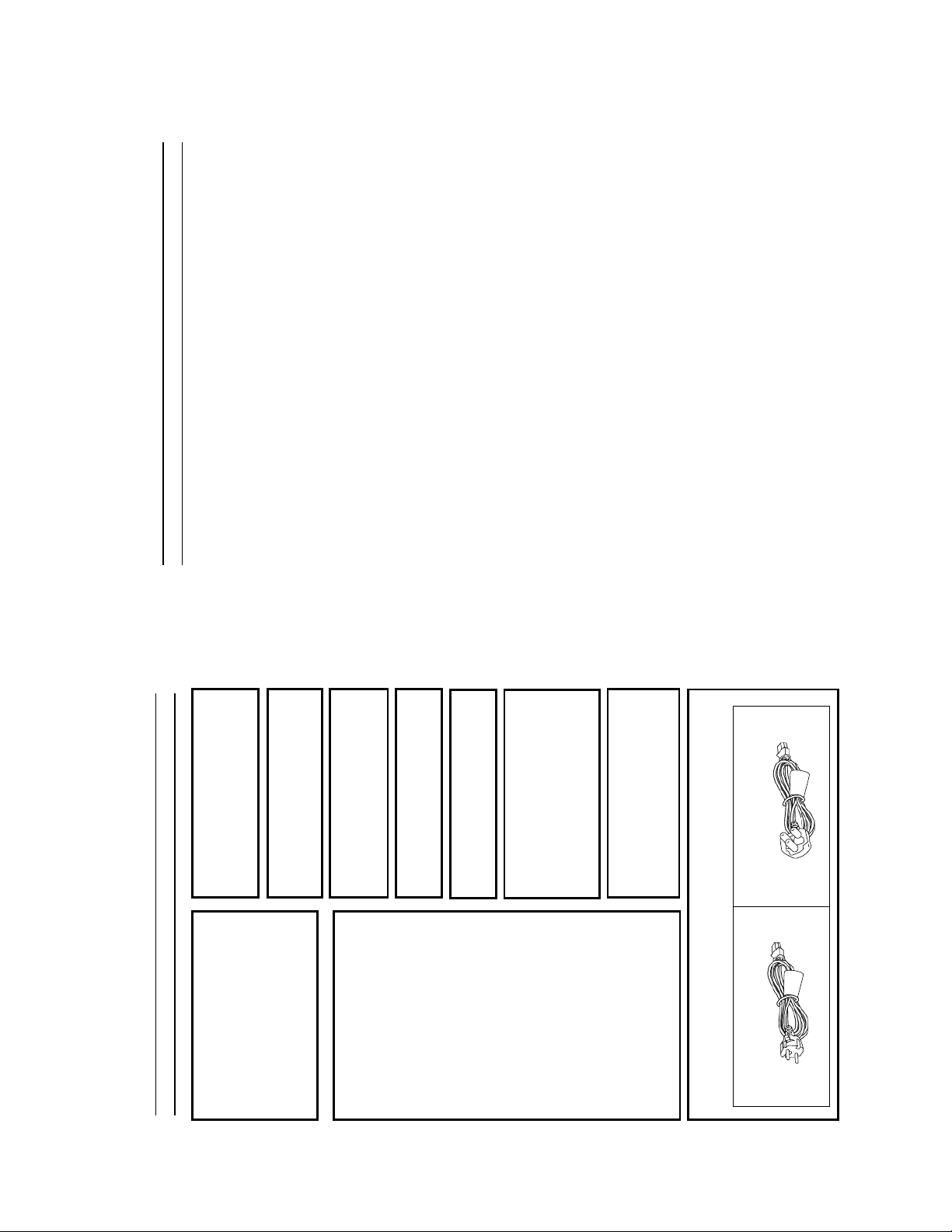
Using a different type or damaged cord
may cause fire or electric shock.
Please use the supplied power cord.
as the kitchen vicinity.
zIntensely vibrating or unstable places.
zPlaces prone to condensation.
zPlaces that generate strong magnetic fields,
For information on maintenance planning and
Replacement is recommended afte r 10000
zPlaces that generate radiation, X-rays or
costs, consult your nearest JVC dealer.
hours of use ( if used in a 25шC environment ).
corrosive gases.
system when not in use.
To save energy, be sure to turn off the
like a monitor or TV.
zPlease do not place heavy objects on the DVR,
Handling the unit
compartment. As injury may result from fingers
zPlease keep the mobile rack into the
5
getting clamped.
unit.
zPlease do not block the ventilation openings.
zAvoid violent shocks to the unit. Do not dr op the
when the unit is not in use.
zPlease remove the AC adapter to save energy
POWER SYSTEM
Connection to the mains supply
This unit operates on voltage of 220 V to 240 V
AC, 50 Hz/60Hz.
WARNING:
TO REDUCE THE RISK OF FIRE OR
CAUTION
To p revent electric shock, do not open the
cabinet. No user serviceable partsinslde. Refer
ELECTRIC SHOCK, DO NOT EXPOSE THIS
servicing to qualified service personnel.
CAUTION
RED colour indications on the operation panel
are provided but they are not safety related.
RED colour indications:
Note:
The rating plate and the safety caution are on
the rear of the unit.
The OPERATE button does not completely
shutoff mains power from the unit, but switches
operating current on and off.
WARNING
It should be noted that it may be unlawful to
rerecord pre-recorded tapes, records, or discs
without the consent of the owner of copyright
in the sound or video recording, broadcast, or
cable programme and in any literary, dramatic,
musical or artistic work embodied therein.
(1) For Recording Button.
FOR U.K. ONLY
If the plug supplied is not suitable for your
socket outlet, it should be cut off and
appropriate one fitted.
4
Caution for AC Mains Lead
Warni ng Notice
FOR YOUR SAFETY (Australia)
three-pin power outlet.
consult a qualified electrician.
SAFETY PRECAUTIONS (FOR EUROPE AND AUSTRALIA)
1. Insert this plug only into effectively earthed
2. If any doubt exists regarding the earthing,
three-core correctly wired.
3. Extension cord, if used, must be
Mains Supply (AC 230 V)
IMPORTANT (In the United Kingdom)
MUST BE EARTHED
WARNING – THIS APPARATUS
s the colours of the wires in the mains lead of
this apparatus may not correspond with the
coloured markings identifying the terminals in
your plug, proceed as follows.
The wire which is coloured GREEN-AND
-YELLOW must be connected to the term inal
in the plug which is marked with the letter E or
by the safety earth symbol or coloured GREEN
or GREEN-AND-YELLOW. The wire which is
coloured BLUE must be connected to the
terminal which is marked with the letter N or
which is coloured BLOCK. The wire which is
coloured BROWN must be connected to the
terminal which is marked with the letter L or
The wires in this mains lead are coloured in
accordance with the following code;
GREEN-and-YELLOW : EARTH
BLUE : NEUTRAL
BROWN : LIVE
coloured RED.
FOR YOUR SAFETY PLEASE READ THE FOLLOWING TEXT CAREFULLY.
Appropriate mains cable must be used in each local area.
FOR CONTINENTAL EUROPE, ETC.
Not to be used in the U.K.
Page 4

7
Table Of Contents
1.1 Product Introduction.................................................................................................................. 9
1.2 Product Features........................................................................................................................ 9
1. PRODUCT FEATURES ..................................................................................................... 9
2.1 Front View ................................................................................................................................ 10
2.2 Rear View................................................................................................................................. 12
2. DESCRIPTION OF THE FRONT/REAR VIEW................................................................ 10
2.3 ALARM In/Out ......................................................................................................................... 13
3.1 Basic Connection ..................................................................................................................... 14
3.2 Hard-Disk Drive Installation ................................................................................................... 18
3.3 System Information .................................................................................................................. 19
3. INSTALLATION............................................................................................................... 14
3.4 Updating System Software ....................................................................................................... 20
4.1 Configuring Recording Settings............................................................................................... 21
4.2 Recording Operations .............................................................................................................. 24
4.3 Playback Operations................................................................................................................ 29
4.4 Search Operations.................................................................................................................... 31
4.5 Backup Operations................................................................................................................... 35
4. BASIC OPERATIONS ..................................................................................................... 21
4.6 Key Lock Operation ................................................................................................................. 38
5.1 REC SETTING ......................................................................................................................... 40
5.2 ALARM SETTING .................................................................................................................... 41
5.3 CLOCK / TIMER...................................................................................................................... 44
5.4 COMMUNICATION ................................................................................................................ 45
5.5 DISK SETTING........................................................................................................................ 48
5. MENU SETUP ................................................................................................................. 39
5.6 SYSTEM ................................................................................................................................... 49
IMPORTANT SAFETY INSTRUCTIONS
AC adapter section
1) Read all of these instructions.
2) Keep these instructions.
3) Heed all warnings.
4) Follow all instructions.
5) Do not use this apparatus near water.
6) Clean only with dry cloth.
6
(including amplifiers) that produce heat.
blades with one wider than the other. A grounding type plug has two blades and a third grounding prong.
The wide blade or the third prong are provided for your safety. If the provided plug does not fit into your
outlet, consult an electrician for replacement of the obs olete outlet.
and the point where they exit from the apparatus.
7) Do not block any ventilation openings. Install in accordance with the manufacturer’s instructions.
8) Do not install near any heat sources such as radiators, heat registers, stoves, or other apparatus
9) Do not defeat the safety purpose of the polarized or grounding-type plug. A polarized plug has two
10) Protect the power cord from being walked on or pinched particularly at plugs, convenience receptacles,
manufacturer, or sold with the apparatus.
When a cart is used, use caution when m oving the cart/apparatus
combination to avoid injury from tip-over.
11) Only use attachments/accessories specified by the manufacturer.
12) Use only with the cart, stand, tripod, bracket, or the table specified by the
damaged in any way, such as power-supply cord or plug is damaged, liquid has been spilled or objects
have fallen into the apparatus, the apparatus has been exposed to rain or moisture, does not operate
normally, or has been dropped.
Apparatus shall not be exposed to dripping or splashing and no objects filled with liquids, such as vases,
shall be placed on the apparatus.
CAUTION – These servicing instructions are for use by qualified service personnel only. To reduc e the
risk of electric shock, do not perform any servicing other than that contained in the operating
13) Unplug this apparatus during lightning storms or when unused for long periods of time.
14) Refer all servicing to qualified service personnel. Servicing is required when the apparatus has been
WARNING - To reduce the risk of fire or electric shock, do not expose this apparatus to rain or moisture.
instructions unless you are qualified to do so.
Page 5

This DVR is a storage media of dig ital video image, which uses hard-disk drives instead of VCR tapes
to store video. It enables you to enjo y the extreme flexibility of digital image archiving instead of clumsy
1. PRODUCT FEATURES
1.1 Product Introduction
tape management, and is compatible with m ost multiplexers in the m arket. Equipped with a range of
9
comprehensive features, such as playback picture-by-pictur e, quick access video recordi ng by time
and event, the upgradeable software of the system , the expandable capacities of hard drive, and muc h
more, the DVR will make your applications far more flexible and effective than ever before. For all, the
DVR is going to prove the timely substitute for Time-lapse VCR.
Ϡʳ St ores video in hard-disk drives instead of VCR tapes.
Ϡʳ Maximum 2 hard-disk drive capability. (One removable)
Ϡʳ Hard-disk drive hot-swapping capability.
Ϡʳ Pre-alarm image recording.
Ϡʳ Capable of working with various k nown multiplexers.
1.2 Product Features
Ϡʳ Time-lapse and real-time recor ding.
Ϡʳ Refresh rate up to 60 IPS (50 IPS for PAL).
Ϡʳ Image quality selectable at 4 different levels for recording.
Ϡʳ Event/Timer/Alarm recording mode.
Ϡʳ Quick search by time, alarm, event, and recording list.
Ϡʳ Fast and slow playback of recorded video at various speeds.
Ϡʳ Single-picture playback.
Ϡʳ On-screen setup menu, title and system timer.
Ϡʳ Password protection.
Ϡʳ Disk-full warning and operation status LEDs.
Ϡʳ RS-232, RS-485 com munication port.
Ϡʳ Remote control via RS-232, RS-485 and Ethernet ports
Ϡʳ Power interruption recovery.
Ϡʳ Operation-status rec ord log.
Ϡʳ Distributing live and recor ded images through TCP/IP network environment.
Ϡʳ Audio function included
Ϡʳ Built-in SD card slot for copying image to SD card
Ϡʳ Support DHCP protocol.
8
6.1 Setup......................................................................................................................................... 52
6.2 Communication Protocol:........................................................................................................ 52
6. RS-232 & RS-485 PROTOCOL....................................................................................... 52
7. MOBILE RACK INSTALLATION..................................................................................... 55
8. SYSTEM DEFAULT......................................................................................................... 58
9. O.S.D MESSAGE ............................................................................................................ 60
10.1 The Network Viewer ............................................................................................................... 61
10.2 The Image Viewer................................................................................................................... 69
10. NETWORK VIEWER AND IMAGE VIEWER................................................................. 61
11. INDEX TABLE ............................................................................................................... 70
12.1 Cable Connections ................................................................................................................. 71
12.2 Configure Your DVR Network Settings .................................................................................. 72
12.3 TCP/IP Communication Software.......................................................................................... 74
12.4 TCP/IP installation ................................................................................................................ 76
12.5 TCP/IP Configuration setting ................................................................................................ 76
12. NETWORK CONFIGURATION ..................................................................................... 71
12.6 Connection Testing................................................................................................................. 77
13. SPECIFICATIONS ......................................................................................................... 79
14. COMPATIBLE MULTIPLEXERS ................................................................................... 80
Page 6
activating.
11
Search button:
Press to enter the search mode to access rec orded video.
simultaneously again.
Up / Down buttons:
Press the two buttons to highlight desired items in the m enu setup mode. For Key Lock operation,
Left / Right buttons:
Press these two buttons to select the desired contents for program ming in the setup menu mode.
press these two buttons simultaneous ly once; to disable Key Lock, press thes e two buttons
223 24
Press to switch between a m ultiplexer-decoded video and the encoded video to be displayed
when connected with a multiplexer. When the button light is on it indicates the unit is displ aying
the decoded video.( The images are not multiplexing . ) In this mode, the unit doesn’t display the
OSD message of the unit on the screen. However, this doesn’t affec t the unit’s OSD message
Monitor button:
Enter Button:
Press to enter a selected item and save the setting in the menu s etup mode.
FWDREV
REC
STOP
PLAY
PAUSE
T-rec
A-recSearch
Enter Monitor
This indicator of the timer recording mode lights up to signal the scheduled record setting is on.
A-rec Indicator:
This indicator of the alarm recording mode lights up to indicate the alarm record setting is on.
DISK Indicator:
which is recorded into ha rd-disk drives. When the butto n light is off it indicates the unit is
displaying encoded video. (The images switch swiftly).
The indicator shows the operation status of the unit’s hard-disk drives. The green light indicates
T-rec Indicator:
OPERATEDISK
the hard-disk drive is storing or retrieving data. The red light signals the hard-disk drive is filling up.
The orange light indicates the hard-disk is retrieving data at disk-full status.
The shuttle can be moved forward and backward for playback in either direction. Turn this left to
Shuttle Ring:
play a recorded video in the reverse direction at faster or slower speeds than the recorded speed.
Turn this right to play a recorded video in th e forward direction at faster or s lower speeds than the
recorded speed.
Jog Dial:
This dial can act in both a forward and a backward direction, as well as step by step. Turn this left
to play a recorded video in the reverse direction. Turn this right to play a recorded video in the
forward direction.
OPERATE Indicator:
Indicates the power status of the unit. The green light indicates the hard-disk drive is
The orange light signals the hard-disk drive is power stand by.
Indicates the power status of the Mobile Rack. The green light indicates the Mobile Rack is
activating.
Indicates the HDD status of the Mobile Rack. The orange light indicates the HDD is storing or
retrieving data.
Mobile Rack Power LED:
Mobile Rack HDD LED:
10
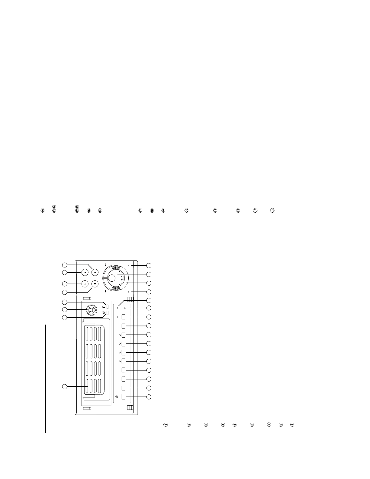
2. DESCRIPTION OF THE FRONT/REAR VIEW
Setup
1 3 4 5 6
Operate Display
7 8 9 10 11 14 13 12 15 16 17 18 19 20 21 22
Press to start recording video into a hard-disk while in the live display mode.(Illum inate red in
REC mode.)
Press this button for at least 3 seconds to power off. Press again to activate the device.
OPERATE button:
Setup button:
DISPLAY button:
Press to show the system operation status on the screen.
Press this to enter the setup menu. Press again to exit the setup m ode.
Press to stop playing back a recorded video or recording video into a hard-disk . (Illuminate green
Hard-disk drive compartment.
The compartment allows you to install a hard- disk drive mostly for back up purposes. Make sure the
drive is well secured with the mounting screws in the mobile rack before you put the rack into th e
compartment. And remember to turn on the power of the compartment by locking it.
Hard-disk compartment lock:
The key lock secures a hard-disk in place. Unlock the compartment befor e you remove the
hard-disk from the slot without turning off the device.
In a playback display, press this to freeze the display. During the freeze, press to displa y one
PLAY button:
frame/field of a picture at a time in the forward direction. (Illuminate green in PAUSE mode.)
PAU SE button:
in STOP mode.)
Press to play back a recorded video from the hard-disk . (Illuminate green in PLAY mode.)
REC button:
STOP button:
2.1 Front View
Page 7
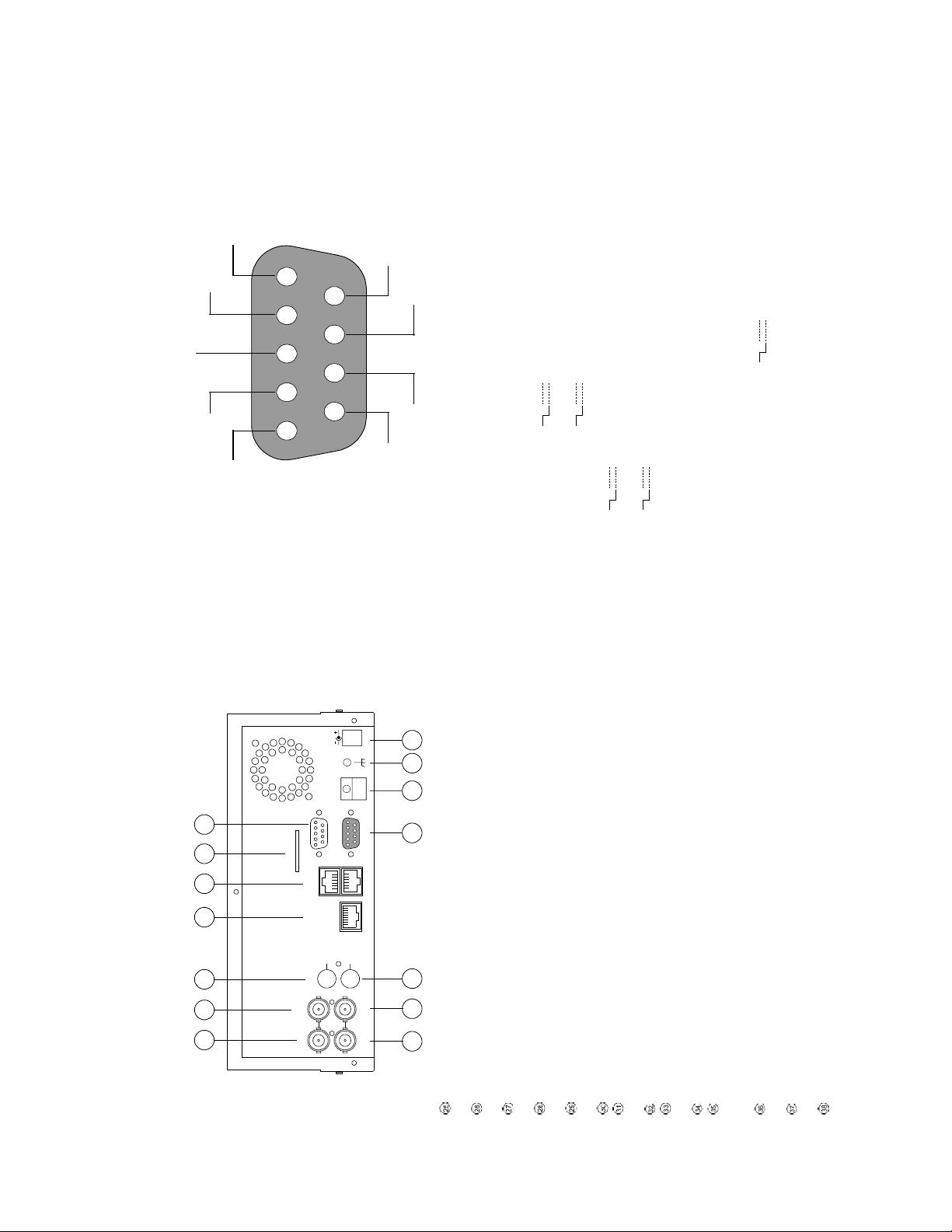
ALARM OUT
DISK FULL
SWITCH OUT
12345
6789
)
)
5V
0V(Active)
5V
0V(Active)
)
5V
0V(Active)
13
ʽTHIS FIGURE IS LOOKED FROM THE REAR
)
)
5V
0V(Active)
5V
0V(Active)
ALARM RESET
RECORD IN GROUND
ALARM IN
NO CONNECTION NO CONNECTION
as buzzers or lights. (
as buzzers or lights. (
1. GND: Ground Contact.
2. ALARM OU T (OUT PUT): This is an alarm output trigger. Connect this to extern al devices such
3. DISK FULL (OUTPUT): This is a disk full output trigger. Connect this to external devices such
4. ALARM RESET (INPUT): This pin connects to an alarm-clear device for clearing an alarm.
(
multiplexer, connects to a multiplexer’s trigger terminal so the multiplexer can switch to use the
6. SWITCH OUT (OUTPUT): This pin, sending out tim ing signals (falling / negative) to a
same recording speed as the DVR.
7. NO CONNECTION
(
5. RECORD IN (INPUT): This pin connects to a record trigger device for starting a record.
8. NO CONNECTION
9. ALARM IN (INPUT): This is an alarm input which can be programmed in the menu system to
Normally Open or Normally Closed. (
2.3 ALARM In/Out
DC12V
I/O
RS-232
10/100
ETHERNET
ALARM
12
SD Card
RS-485
IN
OUT
AUDIO
TO
MONITOR
IN
OUT
TO
MUX'S VCR IN
25 26 27 28 29 30 31
FROM MUX
MAIN MONITOR
VIDEO
2.2 Rear View
34 35 37 38 36
32 33
VIDEO IN Connector: This BNC connector is used to connect the video output from a camera or a
MUX to the DVR.
FROM MUX MAIN MONITOR Connector: This BNC connector is used to connect the live video output
from a MUX to the DVR.
other devices to the DVR.
AUDIO IN Connector: This connector is used to connect the audio output from a camera, a MUX or
networks.
ETHERNET 10/10 0 Connector: This is one standard RJ-45 connector for 1 0/100 Mbps Ethernet
SD CARD Slot: This is used for system software updating and archiving/accessing critical images.
RS-232 Port: The RS-232 communication port functions as a connector to an ex ternal control device.
VIDEO OUT Connector: The connector provides the unit’s composite video signals to a MUX.
MONITOR Connector: The connector provides the unit’s composite video or a MUX’s live sig nal if
connected to a display device.
AUDIO OUT: This provides the unit’s audio signal to a speaker.
ALARM I/O: This is a 9-PIN D-SUB connector including SWITCH OUT, GROUND, ALARM OUT, DISK
FULL, RECORD IN, ALARM RESET, and ALARM IN for connecting with external devices. Please
refer to the next section for details.
Plug Inlet: The inlet connects to an external power supply. Connect 12 V DC UL Listed Class 2 Power
Supply.
Wire Catch: The wire catc h secures the power cord and keeps it in place (so that it does not droop or
hang loosely).
serially connected to expand the storage capacity.
RS-485 Port: The RS-485 communication ports function as connectors when two or more units are
Please refer to RS-232 & RS-485 Protocol for more details.
Ground Screw’s: The ground screw is for chassis terminal.
Page 8
SD Card
RS-232
DC12V
I/O
ALARM
RS-485
10/100
ETHERNET
IN
OUT
AUDIO
TO
FROM MUX
MAIN MONITOR
Please set the MULTIPLEXER option to OFF on the REC SETTING page in the setup menu
Camera
• Please supply power to the unit via the provided AC adapter. Do not use other power sources.
• During recording or playback, please do not unplug the DC or power cord.
when it is connected with a single camera. (Please refer to section 5.1 MULTIPLEXER option)
IN
VIDEO
OUT
MONITOR
TO
MUX'S VCR IN
Note:
Monitor
To match the multiplexer’s recording speed, please set the MULTIPLEXER option to ON on the
CONNECTING WITH A MULTIPLEXER
REC SETTING page in the setup menu when it is connected with a multiplexer. (Please refer to
set recording rate at 60 F/S or 20 F/S.
section 5.1 MULTIPLEXER option)
Caution: Some multiplexers may cause non-updated playback output. In such a case, please
15
CONNECTING WITH A SINGLE CAMERA
Screw
Clamp
3. INSTALLATION
DC IN terminal
DC12V
I/O
RS-232
ALARM
SD Card
RS-485
10/100
ETHERNET
IN
AUDIO
FROM MUX
MAIN MONITOR
IN
VIDEO
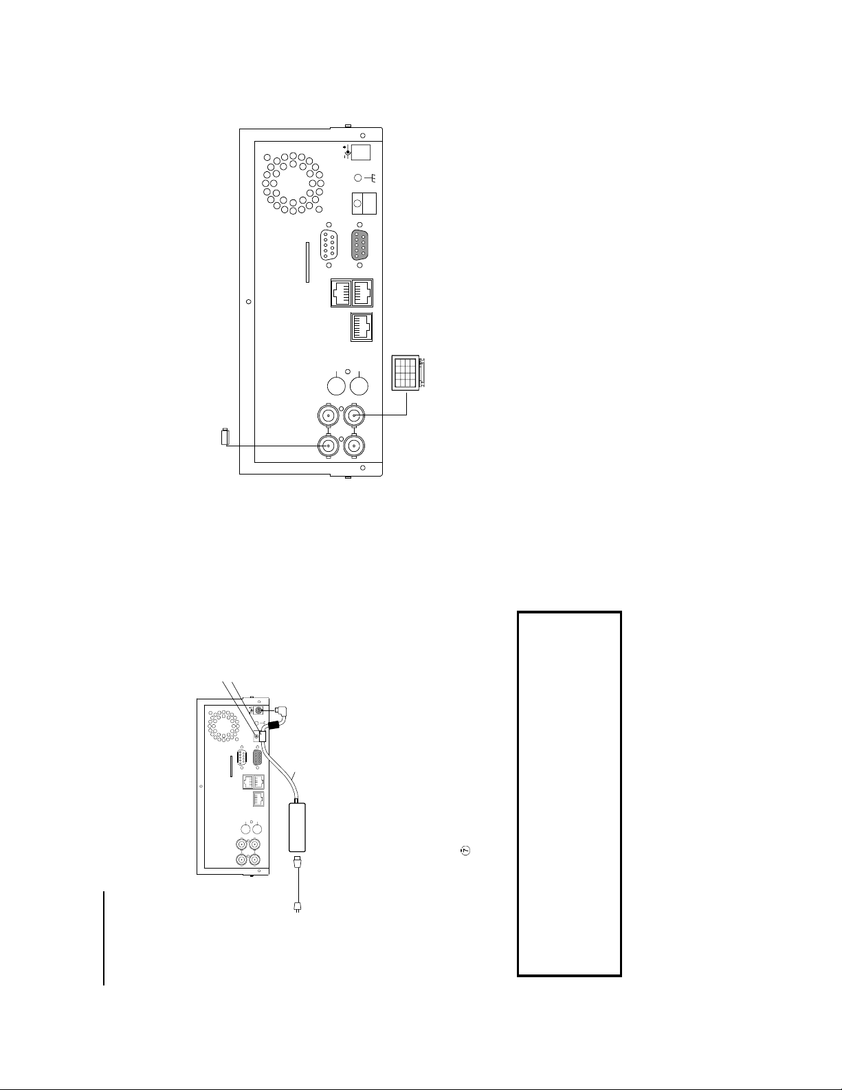
Connect the provided AC adapter to the main unit.
Please follow the instructions and the diagram below to set up the system.
CONNECTIONG TO THE AC ADAPTER
3.1 Basic Connection
DC cord
14
OUT
TO
MONITOR
OUT
TO
MUX'S VCR IN
Provided AC adapter
Provided AC
mains cable
AC
(model:STD-1205)
1. Connect the DC cord of the AC adapter to the DC IN terminal of the main unit.
2. To prevent accidental disconnection of the DC cord, fasten the DC cord with a wire catch.
1) Remove 1 screw followed by the wire catch.
2) Insert the DC cord into the wire catch and fasten the wire catch unto the main unit.
3. Connect the provided power cord to the AC IN terminal of the AC adapter.
4. Connect the power cord to the power socket.
for at least 3 seconds to power off and the OPERATE indicator lights
(OPERATE ON mode)
up orange. (OPERATE OFF mode)
• Press OPERATE button
The orange light signals the hard-disk drive is power stand by.
OPERATE button.
power is not stable. When this is assum ed, please use an uninterruptible power supply (UPS).
When an error message is displayed, please reboot the VR-601 by turning the operation button
Memo
• Even in the OPERATE OFF mode, a small am ount of electricity will still flow into the unit.
• When the unit is in the OPERATE OFF m ode, no operation can be performed except that of the
OFF and ON, or unplug and plug the AC power line.
• It might show an error message "DATA ERROR" and stop recording when the condition of main
* About the location of the buttons, please refer to Page 10 2.1 Front View.
• Power is channeled into the unit and the OPERATE indicator lights up green.
Page 9
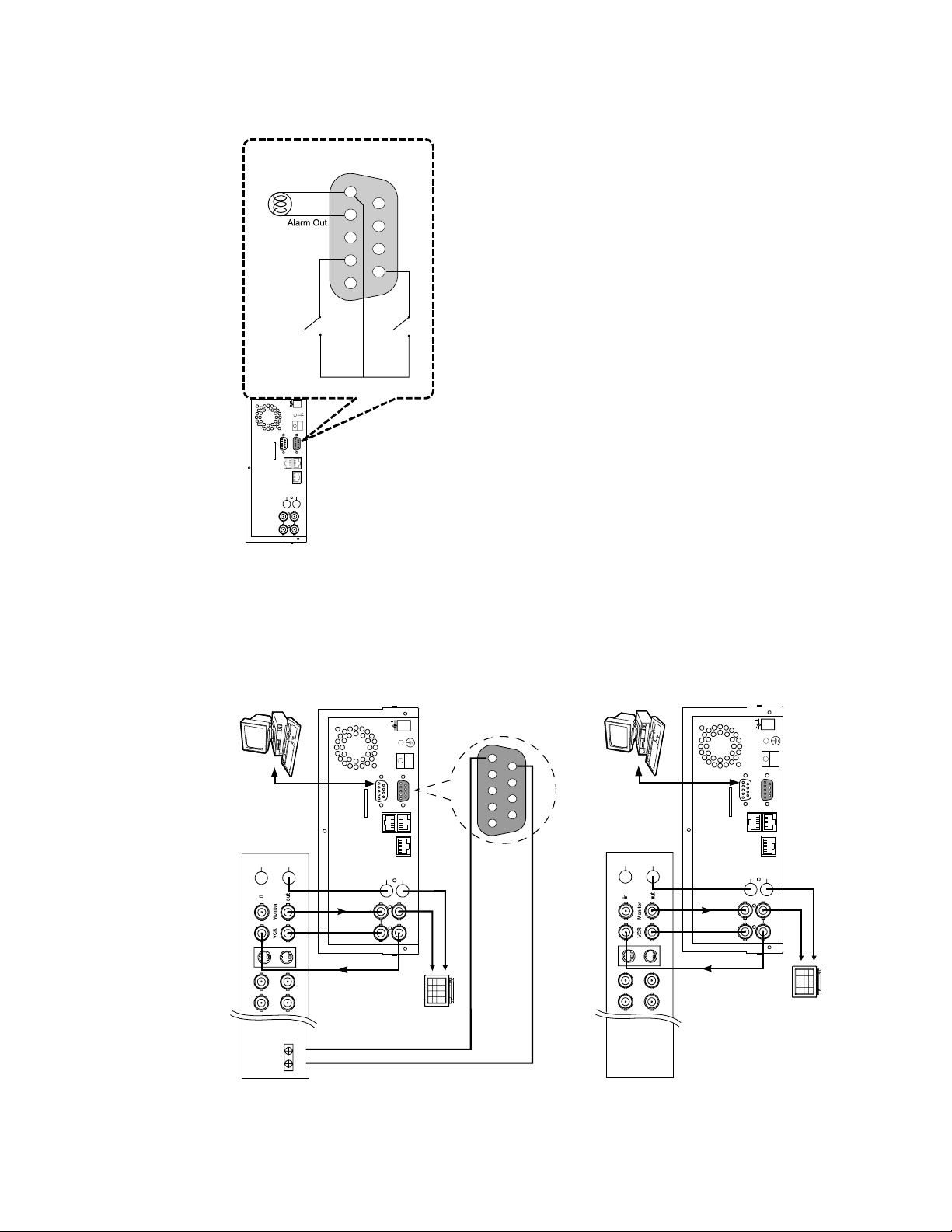
Lamp
12345
6789
AT TACHING AN EXTERNAL DEVICE TO DVR
Connect an alarm out, alarm input, and a peripheral device as shown in the diagram below.
Alarm Reset
(Normally Open)
DC12V
I/O
RS-232
ALARM
SD Card
RS-485
10/100
ETHERNET
IN
OUT
AUDIO
TO
MONITOR
FROM MUX
MAIN MONITOR
IN
OUT
TO
VIDEO
MUX'S VCR IN
Ground
Alarm in
(Normally Open)
DC12V
17
CLOCK SET
Please set the clock before operating the DVR. (For operation details, please ref er to section 5.3
CLOCK/TIMER)
DC12V
Audio in
GROUND
Monitor
12345
6789
SWITCH OUT
Quad
PC
I/O
RS-232
MAIN MONITOR
VIDEO
ALARM
RS-485
10/100
ETHERNET
IN
OUT
AUDIO
TO
MONITOR
IN
OUT
TO
MUX'S VCR IN
Video in
SD Card
IN
OUT
Audio
FROM MUX
S-vide o
Multiplexer
when it is connected with a quad. (Please refer to section 5.1 MULTIPLEXER option)
Please set the MULTIPLEXER option to OFF on the REC SETTING page in the setup menu
Trig In
PC
I/O
RS-232
FROM MUX
MAIN MONITOR
VIDEO
ALARM
RS-485
10/100
ETHERNET
IN
OUT
AUDIO
TO
MONITOR
IN
OUT
TO
MUX'S VCR IN
Video in
Audio in
16
SD Card
IN
OUT
Audio
S-video
Monitor
CONNECTING WITH A QUAD
Page 10
is off) by pressing the Monitor button
The END
of the HDD
Current
Position
the Ethernet
communication,192.168.1.90
Only connected to a single camera.
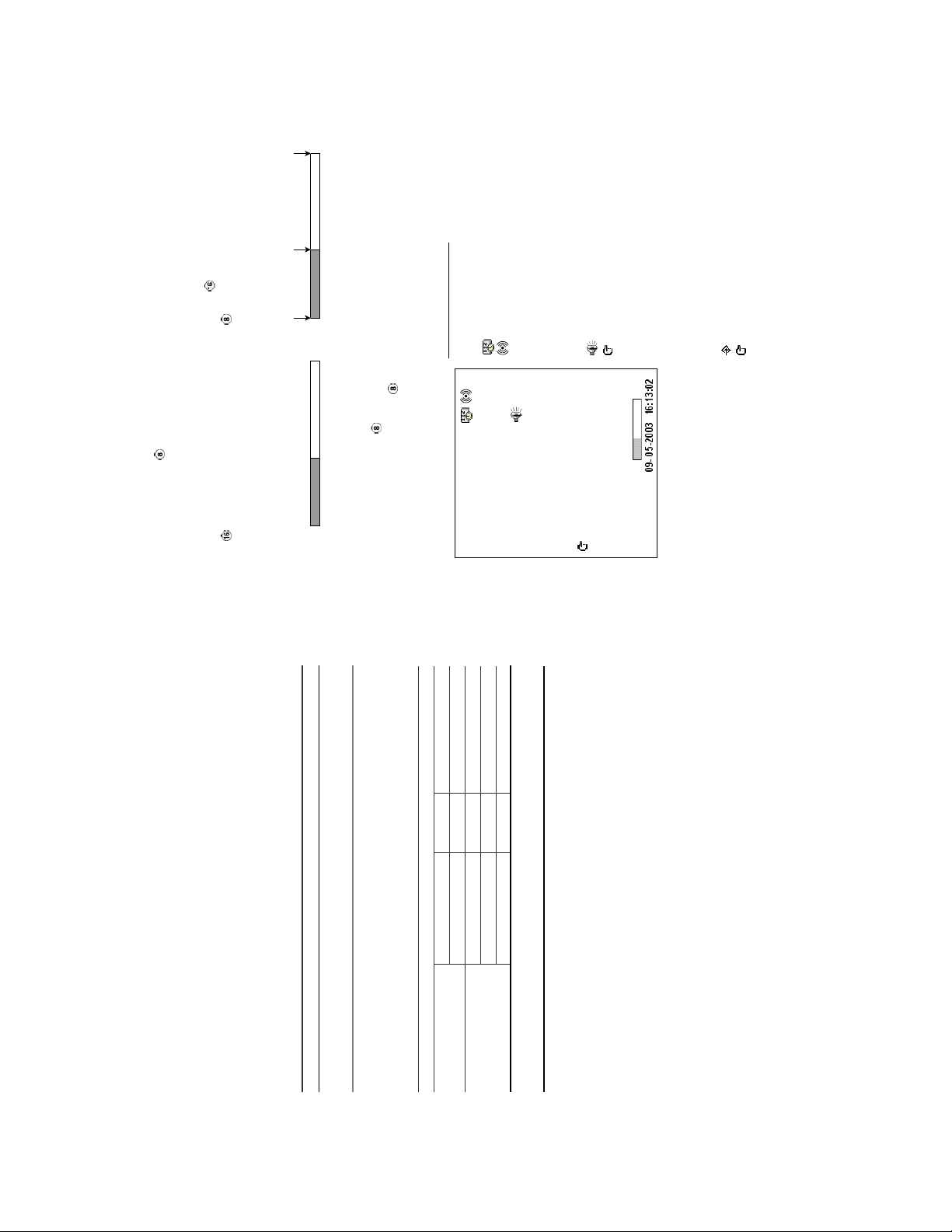
. In the playback mode, the recorded video information is displayed. In the live or
You c an display system settings information as shown on Ta ble 3.3 A belo w at any time by pressing
recording mode, the Manual Recording inform ation is displayed. However, when the DVR is displa ying
the Display button
3.3 System Information
a decoded image from a m ultiplexer, you must first switch the unit to encoded image displaying (The
pictures is switching swiftly and the light of M onitor button
The TOP
of the HDD
): Time r record activated
): Alarm record activated
(1+2: 59G): Total capacity of installed hard-disk, 59 GB
(12.4 HR): Total 12.4 hour recording time available
(
(
(QUALITY: BEST): Record quality setting, BEST
(NTSC): NTSC system
(RATE: 6 HR): Setting of Record time mode, 6 hours
): Indicate which HDD is activated
( ): Audio function activated
(20 F/S): Record speed setting, 20 fields/sec
(MUX: OFF):
(
(9K): The image file size
(P): Y Hard-disk installed; . No hard-disk installed
(HD): Hard-disk Compartment
(SIZE 20G): The capacity of the installed hard-disk
(POS): Percentage of system; R: Recording; P: Playback
(IP : 192 . 168 . 1 . 90): Setting of
): External signal
X): Cannot operate at now
(
(
19
again; the unit will not display any OSD message. Press the
once; the DVR will display the following sample m essage plus the default
(System Time)
(Date)
09-05-2003 16:13:02
(Capacity Used) (Capacity Remaining)
Press the Display button
button one more time to back to the default display.
display. Press the Display button
1+ 2: 59G 12.4 HR
QUALITY: BEST NTSC
RATE: 6 HR 20 F/S
MUX : OFF 9K
Table 3 .3 A. Description of Table 3.3 A
2 Y 39 G 0.0% R
1 Y 20 G 39.5% P
IP : 192 . 168 . 1 . 90
* About the location of the buttons, please refer to Page 10 2.1 Front View.
HD P SIZE POS
following example. By default, the unit displays time, date, and an indicating bar of capacity status on a
Default display
monitor as shown next.
. Each sequential press of the Display button displays a different message detailed in the
3.2 Hard-Disk Drive Installation
18
ST380020A/P 80GB 5400 RPM
6Y120L0-1 120GB 7200 RPM
4A160J0-1A 160GB 5400 RPM
4R080L0-1 80GB 5400 RPM
ST340810A/P 40GB 5400 RPM
Location Jumper
IDE 1 Compartment HD 1 Master (Default)
IDE 2 Compartment HD 2 Master
Manufacturer Model Capacity Rotation
The DVR is equipped with two compartments of hard-disk drive. T he unit usually comes with one
hard-disk drive installed in the com partment HD1, which is default-configured as a master. If you need
a second hard-disk drive to be installed in the com partment HD2 (Mobile), please contact your
distributors or installers for specific instructions on how to i nstall it. Please don’t serve yourself before
consulting your installers. If there is only one hard-disk drive in the mobile compartment, pleas e set the
HD2 USAGE option to REC (Please refer to section 5.5) before proceed recording function. The
jumper-settings arrangement of installed hard-disk drives for the system (Table 3.2 A.) is shown in the
Table 3 .2 A. The jumper settings of hard-disk drives in the system
tables below.
Tab le 3.2 B. Compatible hard-disk drives
Seagate
Maxtor
and are not recommended for use with this product. For the latest updated list on the
recommended hard-disk drives, please contact your dealers or distributors.
NOTE: Hard-disk drives not shown on this list have not been tested by the engineering team
Page 11

4. BASIC OPERATIONS
This section shows you how to operate and manage the DVR when it gets in the way.
Recording Time settings (Recording Rate and Picture Quality Setting)
Recording time will vary depending on the image size, recor ding rate, and the capacity of the hard- disk
drives. Generally, the DVR comes with a built-in hard-disk drive for continuous rec ording from one to
four weeks under most recording conditions. The table below shows the possible recording times based
4.1 Configuring Recording Settings
21
Possible Recording Time HDD=80GB ( hour )
ˀʳ ˀʳ ˀʳ ˇˇˁˇ ˌˈˁˋ ˅˃ˋˁˈ ˆˋ˃ˁˉ ˈˌˋˁˈʳ ˀʳ ˀʳ ˀʳ
ˀʳ ˀʳ ˀʳ ˈˈˁˆ ˄˄ˋˁˋ ˅ˈˈˁˊ ˇˈˌˁˉ ˊ˃ˋˁˌʳ ˀʳ ˀʳ ˀʳ
ˀʳ ˀʳ ˀʳ ˊˆˁ˅ ˄ˈˉˁ˄ ˆˆ˃ˁˈ ˈˋ˃ˁ˃ ˋˉˌˁˈʳ ˀʳ ˀʳ ˀʳ
ˀʳ ˀʳ ˀʳ ˄˃ˋˁˇ ˅˅ˊˁˉ ˇˉˊˁˆ ˊˋˈˁˌ ˄˄˅ˇˁ˃ʳ ˀʳ ˀʳ ʳ
60 30 20 12 5.5 2.4 1.22 0.71 1/4 1/6 1/8
ʳʳ
HIGH
BEST
on a 80GB hard-disk drive at certain refresh rates and the corresponding image qua lity. With one or
more hard-disk drive(s) in operation, please calc ulate the recording tim e using the table below in
accordance with your requirem ent. For a NTSC unit, for exam ple, if the unit is set to record images with
BEST quality at a 60 fps record rate, normally a 80GB hard-disk drive will be filled in 15 hours (See the
gray area in the table). If the total capacit y of 240GB hard-disk drives is in use under the same refresh
rate and picture quality, it will be filled in 45 hours (3 times the rate of a 80GB hard-disk drive).
Set up the REC Time Mode when a multiplexer is connected
If a multiplexer is connected, for optimum image recording and playback, the record speed of the
multiplexer must be correctly adjusted to match the DVR an d set the MULTIPLEXER option on the
setup menu to ON. This can be done by either of methods detailed below.
Connect the SW. OUT terminal in 9-PIN D-SUB connector on the rear panel of the DVR to the
multiplexer’s trigger contact. The DVR will provide the timing signal (Negative/Falling) to the multiplexer.
Thus, if the DVR changes the recording speed, the multiplexer will automatically adjust the record to
match. A 2-hour and 4-hour timing signal in NTSC or a 3-hour and 6-hour one in PAL is constantly
negative/falling.
Audio ON
NTSC (MUX ON)
Image
2 hr 4 hr 6 hr 12 hr 24 hr 48 hr 96 hr 168 hr 480 hr 720 hr 960 hr
BASIC
STANDARD
Quality
Refresh Rate (Field/Sec)
REC Time Mode
20
3.4 Updating System Software
If the system software of the DVR needs to be upgraded, please contact your JVC dealer.
Page 12
23
Possible Recording Time HDD=80GB ( hour )
ˀʳ ˀʳ ˀʳ ˈˆˁ˄ ˋˊˁˇ ˄ˈˆˁˇ ˅ˊˈˁˌ ˇˆˌˁ˄ʳ ˀʳ ˀʳ ˀʳ
ʳʳ
BEST
Audio ON
PAL (MUX OFF)
ˀʳ ˀʳ ˀʳ ˉˉˁˊ ˄˃ˌˁˈ ˄ˌ˃ˁˌ ˆˆˌˁˇ ˈˆ˅ˁ˃ʳ ˀʳ ˀʳ ˀʳ
ˀʳ ˀʳ ˀʳ ˋˌˁˋ ˄ˇˉˁˈ ˅ˈ˅ˁˋ ˇˇ˄ˁ˃ ˉˊˇˁˋʳ ˀʳ ˀʳ ˀʳ
ˀʳ ˀʳ ˀʳ ˄ˆ˃ˁˆ ˅˄˃ˁˈ ˆˈˉˁˋ ˉ˃ˆˁˇ ˋˋˌˁˈʳ ˀʳ ˀʳ ˀʳ
50 25 **17 **10 **5.5 2.9 1.52 0.88 1/4 1/6 1/8
3 hr 6 hr 9 hr 12 hr 24 hr 48 hr 96 hr 168 hr 480 hr 720 hr 960 hr
HIGH
BASIC
STANDARD
Image
Quality
Refresh Rate (Field/Sec)
REC Time Mode
Possible Recording Time HDD=80GB ( hour )
˄ˈˁˇʳ ˄ˋˁ˃ʳ ˆˉˁ˄ ˈˇˁ˅ ˌ˃ˁˆ ˄ˉ˅ˁˉ ˆ˃ˊˁ˅ ˈ˅ˇˁ˄ʳ ˄ˋ˅ˈˁˆʳ ˅ˊ˅ˋˁˌ ˆˉˆ˅ˁˈ
ʳʳ
BEST
Audio OFF
PAL (MUX OFF)
50 25 **17 **10 **5.5 2.9 1.52 0.88 1/4 1/6 1/8
˄ˋˁ˃ʳ ˅˅ˁˋʳ ˇˈˁˉ ˉˋˁˇ ˄˄ˇˁ˄ ˅˃ˈˁ ˇ ˆˋˋˁ˃ ˉˉ˅ˁ˃ʳ ˅ˆ˃ˈˁˉʳ ˆˇˇˊˁ˃ ˇˈˋˋˁˈ
HIGH
Image
3 hr 6 hr 9 hr 12 hr 24 hr 48 hr 96 hr 168 hr 480 hr 720 hr 960 hr
˅˅ˁˋʳ ˆ˃ˁˌʳ ˉ˄ˁˌ ˌ˅ˁˌ ˄ˈˇˁˌ ˅ˊˋˁ ˋ ˈ˅ˉˁˉ ˋˌˋˁˇʳ ˆ˄˅ˌˁ˄ʳ ˇˉˊˋˁ˅ ˉ˅˅ˊˁ˅
ˆ˃ˁˌʳ ˇˈˁˉʳ ˌ˄ˁˆ ˄ˆˉˁˌ ˅˅ˋˁ˅ ˇ˄˃ˁˌ ˊˊˉˁ˄ ˄ˆ˅ˇˁ˃ʳ ˇˉ˄˄ˁˆʳ ˉˋˌˇˁ ˄ ˌ˄ˊˊˁ˃
BASIC
STANDARD
Quality
Refresh Rate (Field/Sec)
REC Time Mode
time of a recording configuration, please refer to the system information of the
DVR. (Please refer to section 3.3 system information for more details.)
NOTE: Recording times on the tables above are estimated. For actual available recording
fields/sec ~ 1/8 fields/sec.
NOTE: No audio function at the refresh rate in NTSC: 60 fields/sec ~ 20 fields/sec, 1/4
fields/sec ~ 1/8 fields/sec.
No audio function at the refresh rate in PAL: 50 fields/sec ~ 17 fields/sec, 1/4
above.
NOTE: An actual recording fields number could be less than the Refresh Rate on the table
would be actually 10 F/S, 5.5 F/S would be actually 5F/S.
would be actually 8.3 F/S, 5.5 F/S would be actually 5F/S.
For PAL and Mux Off Mode, recording rate 17F/S would be actually 12.5 F/S, 10F/S
( This adjustment is to avoid image shaking during playback at the same speed )
** : For NTSC and Mux Off Mode, recording rate 20F/S would be actually 15 F/S, 12F/S
Possible Recording Time HDD=80GB ( hour )
˄ˈˁ˃ʳ ˄ˋˁ˃ʳ ˅ˊˁ˄ ˇˈˁ˄ ˌˌˁˆ ˅˅ˈˁˌ ˇˇ˅ˁˊ ˊˉˋˁ˃ʳ ˅˄ˊˊˁˊʳ ˆ˅ˉ˅ˁ˃ ˇˆˇˉˁˇ
ʳʳ
BEST
Audio OFF
NTSC (MUX ON)
60 30 20 12 5.5 2.4 1.22 0.71 1/4 1/6 1/8
˄ˋˁ˃ʳ ˅˅ˁˈʳ ˆˆˁˋ ˈˉˁˇ ˄˅ˇˁ˅ ˅ˋ˅ˁ ˆ ˈˈˆˁˇ ˌˉ˃ˁ˄ʳ ˅ˊ˅˅ˁ˄ʳ ˇ˃ˊˊˁˉ ˈˇˆˆˁ˃
HIGH
Image
2 hr 4 hr 6 hr 12 hr 24 hr 48 hr 96 hr 168 hr 480 hr 720 hr 960 hr
˅˅ˁˈʳ ˆ˃ˁ˄ʳ ˇˈˁ˄ ˊˈˁˆ ˄ˉˈˁˉ ˆˊˉˁ ˈ ˊˆˊˁˌ ˄˅ˋ˃ˁ˄ʳ ˆˉ˅ˌˁˈʳ ˈˇˆˉˁˋ ˊ˅ˇˇˁ˃
ˆ˃ˁ˄ʳ ˇˈˁ˄ʳ ˉˊˁˊ ˄˄˅ˁˌ ˅ˇˋˁˇ ˈˉˇˁˊ ˄˄˃ˉˁˌ ˄ˌ˅˃ˁ˅ʳ ˈˇˇˇˁˆʳ ˋ˄ˈˈˁ˅ ˄˃ˋˉˉˁ˄
BASIC
STANDARD
Quality
Refresh Rate (Field/Sec)
REC Time Mode
Possible Recording Time HDD=80GB ( hour )
ˀʳ ˀʳ ˀʳ ˈˆˁ˄ ˄˃ˇˁ˅ ˅˄ˉˁ˅ ˆˋˊˁ˅ ˉ˃ˆˁˌʳ ˀʳ ˀʳ ˀʳ
ˀʳ ˀʳ ˀʳ ˉˉˁ˄ ˄˅ˌˁ˃ ˅ˉˇˁˌ ˇˉˊˁˆ ˊ˄ˈˁ˄ʳ ˀʳ ˀʳ ˀʳ
ˀʳ ˀʳ ˀʳ ˋˊˁˇ ˄ˉˌˁˇ ˆˇ˅ˁ˄ ˈˋˌˁˆ ˋˊˉˁˇʳ ˀʳ ˀʳ ˀʳ
ˀʳ ˀʳ ˀʳ ˄˅ˌˁ˃ ˅ˇˉˁˇ ˇˋ˅ˁˊ ˊˌˊˁˆ ˄˄ˆ˄ˁˊʳ ˀʳ ˀʳ ˀʳ
HIGH
STANDARD
60 30 **20 **12 **5.5 2.4 1.22 0.71 1/4 1/6 1/8
BASIC
ʳʳ
BEST
Audio ON
Image
NTSC (MUX OFF)
Quality
Refresh Rate (Field/Sec)
2 hr 4 hr 6 hr 12 hr 24 hr 48 hr 96 hr 168 hr 480 hr 720 hr 960 hr
REC Time Mode
Possible Recording Time HDD=80GB ( hour )
˄ˈˁ˃ʳ ˄ˋˁ˃ʳ ˆˉˁ˄ ˈˇˁ˅ ˄˃ˋˁˇ ˅ˆˇˁˌ ˇˈ˄ˁˋ ˊˊˊˁ˄ʳ ˅˄ˋˉˁˊʳ ˆ˅ˊ˄ˁ˄ ˇˆˈˈˁˇ
˄ˋˁ˃ʳ ˅˅ˁˈʳ ˇˈˁ˄ ˉˊˁˊ ˄ˆˈˁˈ ˅ˌˆˁˉ ˈˉˇˁˊ ˌˊ˄ˁˆʳ ˅ˊˆˆˁˇʳ ˇ˃ˋˋˁˌ ˈˇˇˇˁˆ
˅˅ˁˈʳ ˆ˃ˁ˄ʳ ˉ˃ˁ˅ ˌ˃ˁˆ ˄ˋ˃ˁˊ ˆˌ˄ˁˈ ˊˈˆˁ˃ ˄˅ˌˈˁ˄ʳ ˆˉˇˇˁˉʳ ˈˇˈ˄ˁˋ ˊ˅ˈˌˁ˄
ʳʳ
ˆ˃ˁ˄ʳ ˇˈˁ˄ʳ ˌ˃ˁˆ ˄ˆˈˁ ˈ ˅ˊ˄ˁ˃ ˈˋˊˁˆ ˄˄˅ˌˁˈ ˄ˌˇ˅ˁ ˊʳ ˈˇˉˉˁˌʳ ˋ˄ˊˊˁˋ ˄˃ˋˋˋˁˉ
HIGH
BEST
BASIC
STANDARD
Audio OFF
Image
NTSC (MUX OFF)
Quality
Possible Recording Time HDD=80GB ( hour )
60 30 **20 **12 **5.5 2.4 1.22 0.71 1/4 1/6 1/8
2 hr 4 hr 6 hr 12 hr 24 hr 48 hr 96 hr 168 hr 480 hr 720 hr 960 hr
ˀʳ ˀʳ ˀʳ ˇˇˁˇ ˊˋˁˌ ˄ˇˈˁˆ ˅ˉˋˁˉ ˇˆ˅ˁˋʳ ˀʳ ˀʳ ˀʳ
ʳʳ
BEST
Audio ON
Refresh Rate (Field/Sec)
REC Time Mode
PAL (MUX ON)
ˀʳ ˀʳ ˀʳ ˈˈˁˋ ˌˋˁˌ ˄ˋ˄ˁ˃ ˆˆ˃ˁˊ ˈ˅ˇˁˉʳ ˀʳ ˀʳ ˀʳ
ˀʳ ˀʳ ˀʳ ˊˈˁˆ ˄ˆ˅ˁˈ ˅ˇ˃ˁ˃ ˇˆ˃ˁ˃ ˉˉˉˁ˃ʳ ˀʳ ˀʳ ˀʳ
ˀʳ ˀʳ ˀʳ ˄˃ˌˁˈ ˄ˌ˃ˁˌ ˆˆˌˁˇ ˈˋˌˁˈ ˋˊˌˁ˅ʳ ˀʳ ˀʳ ˀʳ
50 25 17 10 5.5 2.9 1.52 0.88 1/4 1/6 1/8
3 hr 6 hr 9 hr 12 hr 24 hr 48 hr 96 hr 168 hr 480 hr 720 hr 960 hr
HIGH
BASIC
STANDARD
Image
Quality
Refresh Rate (Field/Sec)
REC Time Mode
Possible Recording Time HDD=80GB ( hour )
˄ˈˁˇʳ ˄ˋˁ˃ʳ ˅ˊˁ˄ ˇˈˁ˄ ˋ˄ˁˆ ˄ˈˆˁˉ ˅ˌˋˁ˄ ˈ˄ˈˁ˃ʳ ˄ˋ˄ˉˁ˅ʳ ˅ˊ˄ˌˁˌ ˆˉ˅ˆˁˈ
ʳʳ
BEST
Audio OFF
PAL (MUX ON)
50 25 17 10 5.5 2.9 1.52 0.88 1/4 1/6 1/8
˄ˋˁ˃ʳ ˅˅ˁˋʳ ˆˇˁ˅ ˈˊˁ˃ ˄˃˅ˁˊ ˄ˌˇˁ ˃ ˆˊˉˁˉ ˉˈ˃ˁˉʳ ˅˅ˌˇˁ˅ʳ ˆˇˆˈˁˉ ˇˈˊˊˁ˄
HIGH
Image
3 hr 6 hr 9 hr 12 hr 24 hr 48 hr 96 hr 168 hr 480 hr 720 hr 960 hr
˅˅ˁˋʳ ˆ˃ˁˌʳ ˇˉˁˇ ˊˊˁˇ ˄ˆˌˁˇ ˅ˉˆˁ ˆ ˈ˄˄ˁ˄ ˋˋ˅ˁˌʳ ˆ˄˄ˆˁˉʳ ˇˉˉ˅ˁˊ ˉ˅˄˄ˁˊ
ˆ˃ˁˌʳ ˇˈˁˉʳ ˉˋˁˇ ˄˄ˇˁ˄ ˅˃ˈˁˇ ˆˋˋˁ˃ ˊˈˆˁˆ ˄ˆ˃˄ˁ˅ʳ ˇˈˋˋˁˈʳ ˉˋˊ˄ˁ ˆ ˌ˄ˈˇˁ˅
BASIC
STANDARD
Quality
Refresh Rate (Field/Sec)
REC Time Mode
22
Page 13

25
Timer Manual Timer Ma nual
START END START END
03:00 06:00 08: 00 12:00 14:0 0
scheduled interlude as soon as setting is completed, and come out from menu to start
recording.
operate recording as shown in the diagram below and keep those Im ages in different
files.
NOTE: You can proceed to start the scheduled recording from the current time if it is in the
NOTE: If you activate the recording function before the scheduled recording, the unit will
Recording
Start Manual
it is recordable to 0:00. If you perform Timer Recording ranging ov er the date, please
divide timer schedule into two.
NOTE: The end time can set onl y a larger value than the start time. If the end time is set to 23:59 ,
NOTE: LIVE images may be freezed. But, it isn't a failure.
* About the location of the buttons, please refer to Page 10 2.1 Front View.
4.2.1 Manual Recording
When the DVR is in live display mode, take the following steps to start recording:
4.2 Recording Operations
This section details the way to record video into hard-disk drives. Before commencing with the recording
function, please configure the recording setting properly according to your needs.
is the equal of the
to enter the CLOCK / TIMER
and the “>” button to locate the specific
to record video into a hard-disk drive with the
and set OK to save the setting or
^” button and the “v” button to set the
will light up indicating the DVR is in the recording status.
to turn on and off at specified t imes. This way the DV R will start and stop recording according to
the programmed schedule. Please take the following steps to program the scheduled recording.
to enter the MAIN MENU.
(1) Press the Setup button
(2) Select the CLOCK / TIMER and press the Enter button
to stop recording any time.
message and the REC button
corresponding programmed recording settings. The monitor should display a flashing REC
(1) In live display, press the REC button
(2) Press the STOP button
4.2.2 Timer Recording
(3) To access just recorded video, please refer to section 4.4 for m ore details.
Timer recording provides two periods of time each day in a weekly table which programs the DVR
to enter the REC SCHEDULE table.
, is the equal of the “>” button , is the equal of the “^” button
is the equal of the “v” button .
day/hour/minute and use the “
page.
(4) Press the Enter button
(3) Select the TIMERЁSET.
day/hour/minute you wish.
(5) ϥ Yo u c a n set up by using the “<” button
and
“<” button
ϥ You c a n also set up by using the Shuttle Ring and the Jog Dial.
ϥ The time is displayed in a 24-hour clock format.
(6) After scheduling is completed, press the Enter button
will be on as well. To
to proceed.
24
during the scheduled recording to stop it at an y time. If you wish
select CANCEL to leave the page without saving the settings.
deactivate it, set to OFF.
scheduled recording is on, the red indicator of the Timer Record
(7) To activate the programmed recording schedule, set the REC ENABLE to ON. As the
to continue the scheduled recording, press the REC button
(8) Press the STOP button
* About the location of the buttons, please refer to Page 10 2.1 Front View.
Page 14
4.2.3 Alarm Recording
ALARM SETTING
ALM O PERATION : OFF
REC RATE : 20F/S
REC QUALITY : BEST
AUDIO : OFF
ALM T YPE : NO
ALM DURATION : 0 SEC
MAIN PAG E
PRE- ALARM : OFF
ALARM REC ENABLE
to enter the ALARM SET TIN G.
27
to enter the MAIN MENU.
MAIN MENU
ON.
audio is required, set AUDIO to ON. If pre-alarm rec ording is required, set PRE-ALARM to
REC RATE, REC QUALITY, AUDIO, ALM T YPE, ALM DURATION, and PRE-ALARM settings,
Tak e t h e f o llowing steps to ac tivate the programmed alarm recording. For ALM OPERATION,
please refer to section 5.2 for more details.
(1) Press the Setup button
(3) Set the desired REC RATE, REC QUALITY, ALM TYPE, and ALM DURATION for use. If
(2) Select ALARM and press the Enter button
OPERATION to OFF.
(4) To activate the alarm recording, set ALM O PERATION to ON. To deactivate it, set ALM
RECORD
ALARM
CLOCK / TIMER
COMMUNICATION
DISK
SYSTEM
GOTO ALARM PAGE
4.2.4 Externally triggered Recording
By connecting the RECORD IN of ALARM I/O on the rear panel of the DVR, you can
activate/deactivate the recording function of a DVR. The file will be kept with a prefixed “R”.
Please refer to section 2.3 for more details.
MAIN MENU
RECORD
ALARM
CLOCK / TIMER
COMMUNICATION
DISK
* About the location of the buttons, please refer to Page 10 2.1 Front View.
CLOCK / TIMER
SYSTEM
GOTO CLOCK / TIMER PAGE
REC ENABLE : OFF
CLOCK : SET
TIMER : SET
MAIN PAG E
TIMER REC ENABLE
26
MAIN MENU
RECORD
ALARM
CLOCK / TIMER
COMMUNICATION
DISK
CLOCK / TIMER
MAIN PAG E
SYSTEM
GOTO CLOCK / TIMER PAGE
CLOCK : SET
REC ENABLE : OFF
TIMER : SET
SET REC SCHEDULE
REC SCHEDULE
START END START END
S : 00:00-00:00 00:00-00:00
M: 00:00-00:00 00:00-00:00
T : 00:00-00:00 00:00-00:00
TO MOVE TO CHANGE
OK CANCEL
T : 00:00-00:00 00:00-00:00
W: 00:00-00:00 00:00-00:00
F : 00:00-00:00 00:00-00:00
S : 00:00-00:00 00:00-00:00
Page 15

m
or rewind to replay the file if required)
to replay the file if required)
4.3 Playback Operations
to play a latest recorded video)
will light up indicating that the DVR is in the playback status.
θSTOPιШθPLAYι…………Play the file from the stop position
θPlay to the end of the fileι…Show the end ing message (use search functions
θPlay to the end of the fileι…………Show the ending message (Search again or rewind
θSTOPιШθPLAYι…………………Play the file from the stop position
If HD2 USAGE set to BACKUP, playback starts from the TOP of the current HDD.
(In live mode, directly press the PLAY button
This section shows you how to operate the fast, slow, and single-picture playback functions, and
details how the unit is to playback a f ile in a different operation status. Please ref er to the following
paragraphs specifying the relevant details. When playing a file, the m onitor should display a flashing
PLAY message and the PLAY button
Operation Status
RECШθSTOPιШθPLAYι……………………………… Play the latest recorded file
A. From REC mode to Playback mode
SearchШθPLAYι………………………………………… Play a selected file
B. Search to play back a particular recorded video
C. Playback from the TOP of the HDD
θStop : Press the “STOP” button for three secondsιШθPLAYι..Playback from the TOP of the HDD
If HD2 USAGE set to REC, playback starts form the TOP of HDD1.
There are 7 speeds available for playback: 1x, 2x, 4x, 8x, 16x, 30x and 100x
4.3.1 Fast Forward/Reverse
While playing back recorded video at recorded speed:
to the right to view the recorded video in the forward direction at a
speed faster than the recorded speed. Each subsequent turn of the shuttle to the right
Forward: Turn the Shuttle dial
increases the forward rate, as 2x, 4x, 8x, 16x, 30x and 100x.
to the left to view the recorded video in the reverse direction at a
speed faster than the recorded speed. Each subsequent turn of the shuttle to the left
Reverse: Turn the Shuttle dial
and “>” button .
to return to the normal speed of playback.
increases the reverse rate, as -1x, -2x, -4x, -8x, -16x, -30x and -100x.
Normal: Release the Shuttle dial
* You can also operate by using “<” button
29
* About the location of the buttons, please refer to Page 10 2.1 Front View.
Normal
Normal Alarm
28
Normal Alarm Nor mal
Speed
diagrams below.
NOTE: The status of recording operations w hen an alarm takes place are shown in the
Manual or Externally
1
Actual Record ing
Alarm Take s Place
Tri ggered Recording
Timer Record ing
2
Normal Alarm Nor mal
Speed
Actual Record ing
Alarm Take s Place
Timer Record ing
3
Speed
Actual Record ing
Alarm Take s Place
Timer Record ing
4
Alar
Speed
Actual Record ing
Alarm Take s Plac e
Page 16

to enter the DISK SETTING page.
to access the complete list of recorded
to
3 12-02-03 14:20:25 2.05M
HD 1
1 11-11-02 12:20:23 10.1M
4 01-02-03 17:20:46 5.32M
R 5 02-14-03 16:11:55 24. 2M
T 6 02-17-03 13:30:22 36. 6M
7 02-20-03 18:33:54 6.41M
A 2 11-1 8 -02 13:30:16 2.34M
8 02-27-03 19:21:12 92. 3M
31
4.3.4 Play Back Recorded Video from a HDD of the mobile rack
To play back a recorded video f rom a HD2, take the following steps:
to enter the setup menu.
(1) Press the Setup button
(2) Select DISK and press the Enter button
please refer to the next section 4.4 (Search Operations).
(3) Set the HD2 USAGE to REC and then exit the setup menu.
(4) Use the search function to access desired recorded video. For specific operation details
to switch between decoding and
it might not work correctly.
NOTE: If the play back is performed reversely ( fast / slow / step by step) from HD2 to HD1,
4.4 Search Operations
This section shows you how to access recorded video.
4.4.1 Full List Search
Tak e the f ollowing steps to proceed with the full-list search function.
to enter the search mode.
(1) Press the Search button
(2) Select the FULL LIST and press the Enter button
video.
“^” and “v” buttons, to select a video; press the “<”
“>” buttons, to flip over a page.)
FULL LIST
ALARM LIS T
TIME SEARCH
THUMBNAIL
display the selected video.
(3) Highlight the specific recorded video of your requirement and press the Enter button
and
(Key Operation: Press the
SEARCH
SD CARDʳ
NOTE: T: Timer recording; R: External trigger recording; A: Alarm recording.
NOTE: The maximum number of lists, for a respective HDD, is 3000.
* About the location of the buttons, please refer to Page 10 2.1 Front View.
and “>” button .
to the right to view the recorded vi deo in the forward
for the slow playback mode.
(50F/S~25F/S for PAL), the playback speed is half at recorded speed.
that is recorded by 60F/S (PAL 50F/S) or recorded by complex alarm-in, the speed of
Fast Forward/Reverse may be slower than displayed speed.
video from a multiplexer, the playback speed will only display in encoding
(multiplexing) the mode. Press the Monitor button
encoding modes.
There are 4 speeds available for a slow playback: 1/2, 1/4, 1/8, 1/16.
While playing back recorded video at the recorded speed:
(1) Press the PAUSE button
(2) Forward: Tur n the Shuttle dial
NOTE: When Normal playing a recorded video from a multiplexer at 60 F/S~30F/S
NOTE: The speed that is displayed is a standard. For example, while playing back the movie
NOTE: The playback speed will be displayed on the screen. However, when playing a recorded
4.3.2 Slow Forward/Reverse
to the left to view the recorded video in the revers e
direction at a speed slower than the recorded speed. Each su bsequent turn of the
shuttle to the right increases the forward rate, as 1/2, 1/4, 1/8, and 1/16.
(3) Reverse: Turn the Shuttle dial
direction at a speed slower than the recorded speed. Each su bsequent turn of the
shuttle to the left increases the reverse rate, as -1/2, -1/4, -1/8, and -1/16.
and then press the PLAY button to return to the
normal speed of playback.
* You can also operate by using “<” button
(4) Normal: Release the Shuttle dial
4.3.3 Play Back Picture-by-picture
While playing back recorded video at the recorded speed:
for the picture-by-picture mode.
(1) Press the PAUSE button
can only fu nction in a forward direction; t he other, JOG dial
mode, but the PAUS E button
(2) There are two ways, by PAUSE button or by JOG, available to play in the picture-by-picture
, can act in both a forward and a backward direction, as well as picture-by-picture.
to display one frame/field of a picture at a time in the forward
:
Press the PAUS E button
By PAU SE button
direction. (When playing back video recorded by a multiplexer, each sequential press of
will display each camera in sequence.)
the PAUSE button
:
By JOG dial
clockwise to display one frame/field of a picture at a time in the forward
Turn the JOG dial
counterclockwise to display one frame/field of a picture at a
to return to the normal speed of playback.
time in the backward direction.
direction. Turn the JOG dial
(3) Press the PLAY button
30
* About the location of the buttons, please refer to Page 10 2.1 Front View.
Page 17

THUMBNAIL
03 / 13 / 2003
MM DD YEAR
to access the thumbnail page.
, the “>” button , the “^” button and the
33
4.4.4 THUMBNAIL Search
Take the following steps to proceed with the thumbnail search function.
to enter the search mode.
(1) Press the Search button
(2) Select the THUMBNAIL and press the Enter button
(3) Set the date you wish to search for the recorded video.
to access the complete list of
to start searching and displaying the concerned image.
(4) Press the Enter button
to
ϥ You c a n set up by using the “<” button
to move eye focus.
“v” button
is the equal of the “<” button , is the equal of the “>” button , is the equal of
ϥ You can also set up by using the Shuttle Ring and the Jog Dial to move eye focus.
^” button and is the equal of the “v” button .
the “
HD 1
.
to enter the next level. If you want to return the previous level, please press the
FULL LIST
ALARM LIS T
TIME SEARCH
THUMBNAIL
button
Setup button
10 Seconds and 1 Second. Select the specific field of your requirement and press the Enter
(5) There are 5 levels of recording range modes to choose fr om: 1 Hour, 10 Minutes, 1 Minute,
A 1 11-18-02 13:22: 16 16. 3M
A 2 02-14-03 16:55:45 15. 6M
A 3 02-17-03 13:22:38 17. 8M
PLAY button
(6) Once reaching the critical point at any level, the user can start playback by just clicking the
SEARCH
SD CARDʳ
* About the location of the buttons, please refer to Page 10 2.1 Front View.
TIME SEARCH
to access the time-setting page.
MM DD YEAR HH MM
11 / 17 / 2002 00 : 00
4.4.2 Alarm list Search
Take the following steps to proceed with the alarm-list search function.
to enter the search mode.
(1) Press the Search button
alarm-event recorded video.
(2) Select the ALARM LIST and press the Enter button
(3) Highlight the specific recorded video of your requirement and press the Enter button
“^” and “v” buttons, to select a video; press the “<”
display the selected video.
(Key Operation: Press the
“>” buttons, to flip over a page.)
and
SEARCH
32
to enter the search mode.
FULL LIST
ALARM LIS T
TIME SEARCH
THUMBNAIL
SD CARDʳ
Take the following steps to proceed with the time search function.
(1) Press the Search button
(2) Select the TIME SEARCH and press the Enter button
(3) Set the time period you wish to search for the recorded video.
to start searching and displaying the concerned image.
(4) Press the Enter button
(5) If no video is found, please return to the time-setting page and repeat steps (3) and (4) again
FULL LIST
ALARM LIS T
TIME SEARCH
THUMBNAIL
for another search.
SEARCH
SD CARDʳ
4.4.3 TIME Search
* About the location of the buttons, please refer to Page 10 2.1 Front View.
Page 18

MAIN PAG E
BACKUP----------------FULL
ALARM
SELECT
BACKUP ALL TO HD2
35
to proceed.
BACKUP BACKUP
MAIN PAG E
SET HD2 USAGE
DISK SETTING
REFORMAT
HD2 USAGE
to proceed.
DISK SETTING
to enter the DISK SETTING page.
to enter the setup mode and select the DISK.
REFORMAT
HD 2 USAGE---------- REC
4.5.1 Mobile Rack HD Backup
There are three ways available to duplicate the recorded video from HD 1 (Fixed HD) to HD 2
(Mobile Rack HD). Please take the following steps to proceed.
(1) Set HD 2 to BACKUP first. Take the following steps.
4.5 Backup Operations
to display
to access the complete list of JPG files.
z Press the Setup button
z Highlight DISK and press the Enter button
z Then set HD 2 USAGE to BACKUP.
MAIN MENU
RECORD
ALARM
SD CARD JPG FILE
^” and “v” buttons, and , to highlight BACKUP, select FULL, then press
the Enter button
DISK
SYSTEM
COMMUNICATION
F0001.JPG
GOTO DISK PAGE
F0002.JPG
F0003.JPG
F0004.JPG
F0005.JPG
z Stay on the DISK SETTING page.
z Use the “
(2) FULL: Duplicate all the recorded video from HD1 to HD2.
CLOCK / TIMER
F0000.JPG
MAIN MENU
RECORD
ALARM
CLOCK / TIMER
COMMUNICATION
DISK
SYSTEM
GOTO DISK PAGE
^” and “v” buttons, and , to highlight BACKUP; select ALARM, then
z Stay on the DISK SETTING page.
z Use the “
ALARM : Duplicate all the alarm-event recorded video from HD 1 to HD2.
press the Enter button
* About the location of the buttons, please refer to Page 10 2.1 Front View.
Take the following steps to proceed with the SD card search function.
4.4.5 SD CARD Search
(1) Insert a SD Card into the SD card slot of the rear unit.
to enter the search mode.
(2) Press the Search button
(3) Select the SD CARD and press the Enter button
(4) Highlight the specific JPG file of your requirement and pres s the Enter button
the image.
(5) If you need another, please return to the SD card JPG file list page and repeat steps (3) and
34
and then select the “Yes” to delete the image.
list page and highlight the specific JPG file of your requirement and press the Setup
FULL LIST
ALARM LIS T
TIME SEARCH
THUMBNAIL
(4) again for another search.
SEARCH
SD CARDʳ
button
NOTE: If you would like to delete JPG file in the SD card, please return to SD CARD JPG FILE
* About the location of the buttons, please refer to Page 10 2.1 Front View.
Page 19

O
S
G
4.5.2 Secure Digital Card (SD Card) Backup
The SD card slot of the rear unit has three functions as shown below:
Please take the following steps to archive a critical image in a SD card.
1. Archi ve Single image Clips into SD Card
(1) Insert a SD Card into the SD card slot of the rear unit.
is off
to get into
to enter the SYSTEM SETTING page.
37
to freeze the desired pictures.
to save the image in the SD Card.
to enter the setup mode and select the SYSTEM.
SAVE TO J0000.JPG
multiplexer, you must get into the multiplexing m ode and display picture b y picture in
order to select the desired im age for archiving. Press the Monitor button
the multiplexing mode under this m ode so that the light of the Monitor button
and the pictures are switching swiftly)
(2) Start playing back the recorded video. (When playing back recorded video made by a
(3) Press the PAUSE button
The quantity of pictures that can be stored depends on the SD card capacity. It depends
(4) Press the Enter button
on SD card capacity how many pictures can be stored. You can have the saved images
printed out in any computer. The image is stored in the JPEG compressed form at. If
more than one clip is stored in a SD card, file names will be assigned in sequence as
shown below.
Manufacturer Capacity
The VR-601 offers a quick setup method by using a SD card. If a user wants to set many
VR-601 devices with the same settings, the VR-601 could save the whole setting in the SD card,
then transfer it to another DVR.
SAVE TO J0001.JPG
…
2. Backup the System setting info into SD Card.
SAVE TO J000N.JPG
zInsert a SD card into the SD card slot.
zPress the Setup button
Save the whole setting into the SD card:
zHighlight SYSTEM and press the Enter button
zSet SD SETUP to SAVE. Then the system setting info will auto save into SD card.
Table 4.5.2 A. Compatible SD Cards
not recommended for use with this product. For the lates t updated list on the
Panasonic 32MB ~ 128MB
PQI 32MB ~ 128MB
Hagiwara 32MB ~ 128MB
NOTE: SD Cards not shown on this list have not been tested by the engineering team and are
recommended SD Cards, please contact your dealers or distributors.
* About the location of the buttons, please refer to Page 10 2.1 Front View.
to proceed.
DISK SETTING
REFORMAT
HD2 USAGE
MAIN MENU
RECORD
ALARM
MAIN PAG E
BACKUP----------------FULL
ALARM
SELECT
DISK
SYSTEM
CLOCK / TIMER
COMMUNICATION
BACKUP ALARM TO HD2
E
K PA
DI
T
^” and “v” buttons, and , to highlight BACKUP, select SELECT and
z Stay on the DISK SETTING page.
z Use the “
SELECT: Duplicate a particular recorded video from HD1 to HD2.
to list all the recorded video.
^” and “v” buttons, and , to select the desired clip and press the
then press the Enter button
z Press the “
to mark it.
Search button
z After completing the selection, press the Enter button
DISK SETTING
MAIN MENU
REFORMAT
RECORD
MAIN PAG E
HD2 USAGE
BACKUP----------------FULL
ALARM
SELECT
ALARM
CLOCK / TIMER
COMMUNICATION
DISK
SYSTEM
BACKUP PART TO HD2
GO TO DISK PAGE
HD1
TOTAL: 41 M
A 1 2001-02-01 12:20
2 2001-02-01 03:30 +
READY TO GO
OK CANCEL
A 3 2001-03-02 04:20 +
4 2001-04-01 13:30
movies. This is not a defect.
“HD2 SPACE NOT ENOUGH” will be displayed on the screen. Please, insert a larger
NOTE: If the capacity of HD 2 is not sufficient to store all selected video, a warning message
In such a case, it will disappear by opening the Search menu or starting playing back
capacity of hard-disk drive and start the process all over again.
NOTE: The black back will remain (1/7 of screen from the bottom) after executing HD BACKUP.
* About the location of the buttons, please refer to Page 10 2.1 Front View.
36
Page 20

39
There are 6 categories for operation setting in the setup m enu system as shown below. The following
5. MENU SETUP
sections will instruct you step by step to configure the operation setting and state each menu’s purpose and
to enter the SYSTEM SETTING page.
to access the setup menu. Once inside the menu system, the on-screen
options. Press the Setup button
menu allows you to set up the key features of the unit. The functions of various buttons within the
menu-setup mode are described in the paragraphs below.
SYSTEM
OPERATION LOG : ENTER
MENU BACKGND : 2
MAIN MENU
RECORD
ALARM
CLOCK / TIMER
COMMUNICATION
MAIN PAGE
BUZZER : ON
PAS SWO RD : SET
SETUP PWD : OFF
DEFAULT : LOAD
SD SETUP : SAVE
VERSION : ENTER
DISK
SYSTEM
VIEW OPERATION LOG
KEY FUNCTIONS
:
Setup button
Press to enter the setup menu. Press again to exit the setup m ode.
“<” and “>” buttons (as shown below) for
and :
:
^” “v” buttons and :
“
Press to select the desired item or entry for setting.
Press to highlight the desired option or to select the context for setting.
“<” “>” buttons
Enter button
FWDREV
REC
STOP
PLAY
PAUSE
Press to enter the selected item and to save the setting.
A-recSearch
Enter Monitor
:
Shuttle Ring
OPERATEDISK
T-rec
Turn to highlight the desired option or to select the context for setting.
:
Jog Dial
Turn to select the desired item or entry for setting.
* About the location of the buttons, please refer to Page 10 2.1 Front View.
38
to enter the setup mode and select the SYSTEM.
Transfer the system setting info of DVR to another:
zInsert the SD card which has stored the system setting info into the DVR.
zPress the Setup button
zHighlight SYSTEM and press the Enter button
zThen set SD SETUP to LOAD.
MAIN MENU
RECORD
ALARM
CLOCK / TIMER
COMMUNICATION
DISK
11 14
Setup
Operate Display
Updating System Software (Please refer to section 3.4 for more details.)
SYSTEM
GOTO SYSTEM SETTING
3.
The Key lock operation protects the unit against unauthorized use by disabling the entire front
panel controls. Simultaneously press these two
at least 3 seconds to lock the unit; to release the Key Lock, simultaneously press these two
buttons again.
4.6 Key Lock Operation
* About the location of the buttons, please refer to Page 10 2.1 Front View.
Page 21

ALARM SET TIN G
ALM O PERATION : OFF
REC RATE : 20F/S
REC QUALITY : BEST
AUDIO : OFF
ALM T YPE : NO
ALM DURATION : 0 SEC
MAIN PAG E
PRE- ALARM : OFF
ALARM REC ENABLE
41
This option determines the way to record sound if necessary.
AUDIO:
ON: Enables AUDIO recording.
OFF: Disables AUDIO recording.
This menu allows users to program the configuration of alarm recording only when an alarm input is
activated. The device will record as long as the alarm input is activated.
MAIN MENU
RECORD
ALARM
CLOCK / TIMER
COMMUNICATION
DISK
OFF: The device ignores the alarm signal when it detects an alarm input.
the pictures and a message will be displayed.
NOTE: When the Alarm Operation is ON, The image softw are (Network Viewer) doesn't show
the REC page.
are 5 different record speeds you can select f rom: 50F/S (50 fields per second), 25F/S, 17F/S, 10F/S,
REC RATE:
This option is for the purpose of adjusting the number of pictures recorded every second into a storage
disk when an alarm input is activated. For a NTSC unit, there are 5 different record speeds you can
and REMAIN. If you select REMAIN for use, the device will record im ages at the same speed as set on
select from: 60F/S (60 fields per second), 30F/S, 20F/S, 12F/S, and REMAIN. For a PAL unit, there
* About the location of the buttons, please refer to Page 10 2.1 Front View.
40
SYSTEM
GOTO ALARM PAGE
ON: The device activates the alarm recording when it detects an alarm input.
ALM O PERATION:
This option determines whether to activate/deactivate the alarm recording when it detects an alarm input.
12(10), 5.5(5.5), 2.4(2.9), 1.22(1.52), 0.71(0.88) fields/sec
Quad processor.
For optimum image recording please set this option to ON when the DVR is connected to a
NOTE: Audio function can only be activated in the following refresh rate in NTSC(PAL):
multiplexer for use. Set this option to OFF when it is only connected to a single camera or
MULTIPLEXER:
5.2 ALARM SETTING
REC SETTING
REC RATE : 20 F/S
REC QUALITY : BEST
DISK FULL : REWRITE
AUDIO : OFF
MAIN PAG E
MULTIPLEXER : ON
SET REC RATE
MAIN MENU
per second), 30F/S, 20F/S, 12F/S, 5.5F/S, 2.4F/S, 1.22F/S, 0.71F/S, 1 F/4S, 1F/6S, and 1F/8S.
recorded.
ϥ For a NTSC unit, there are 11 different recording rates you can select from: 60F/S (60 fields
This page allows you to set the recording rate and recording quality, and enables you to continue
recording when the disk is full.
RECORD
ALARM
CLOCK / TIMER
COMMUNICATION
DISK
This option is for adjusting the number of pictures recor ded every second into a storage disk.
SYSTEM
GOTO REC PAGE
The recording rate controls the frequency at which the num ber of video pictures can be
REC RATE:
Please refer to the table in section 4.1 for details.
ϥ For a PAL unit, there are 11 different recording rates you can select from: 50F/S (50 fields
per second), 25F/S, 17F/S, 10F/S, 5.5F/S, 2.9F/S, 1.52F/S, 0.88F/S, 1 F/4S, 1F/6S, and 1F/8S.
5.1 REC SETTING
for a PAL unit) resolution
NOTE: The 60 f/s (50 f/s for a PAL unit) recording rate can only function in a 352x240 (352x288
This option determines the image quality to be recorded. T he DVR stores images in the
compressed format and allows the image quality to be alter ed by the image size. T here are 4
levels of image quality you can select from: BEST, HIGH, STANDARD, and BASIC. Selecting
the BEST image for use provides higher-resolution recorded images, and nor mally takes up
more storage space than a HIGH, STANDARD or BASIC image does.
REC QUALITY:
This option determines the way to utilize storage media in case of a full disk.
DISK FULL:
REWRITE: When the hard-dis k is full, the device continues recording by displacing the old data.
STOP: When the hard-disk is full, the device will stop recording.
* About the location of the buttons, please refer to Page 10 2.1 Front View.
Page 22

A
A
43
For PAL and Mux Off Mode, recording rate 17F/S would be actually 12.5 F/S.
ON: Enables this function.
OFF: Disables this function.
PRE- ALARM:
This option determines that images prior to an alarm occurs will be recorded in the hard- disk drive.
When an alarm is triggered the device will record the image prior to the alarm for 5 seconds in NTSC
(**20 fields/sec) or 6 seconds in PAL (**17 fields/sec).
recording would not take effect.
NOTE: If the device is already under recording mode before alarm occur, the pre-alarm
( This adjustment is to avoid image shaking during playback at the same speed )
** : For NTSC and Mux Off Mode, recording rate 20F/S would be actually 15 F/S
Reset
Duration
Alarm
Compression Ratio
Best High Standard Basic
Image Quality
Image Size 48KB 32KB 21KB 16KB
ON: Enables AUDIO recording.
OFF: Disables AUDIO recording.
This option determines the image quality to be recorded when an alarm input occurs. There are 4
the level of image quality with the corresponding compression ratio and image size.
levels of image quality to choose from: BEST, HIGH, STANDARD, and BASIC. The table below shows
REC QUALITY:
AUDIO:
This option determines the way to record sound if necessary.
12(10), 5.5(5.5), 2.4(2.9), 1.22(1.52), 0.71(0.88) fields/sec
NOTE: Audio function can only be activated in the following refresh rate in NTSC(PAL):
ALM TYPE:
open in normal conditions and closes in case of activation.
closed in normal conditions and opens in case of activation.
NC: Normally Closed. This is to be used with the type of alarm sensor whose c ontact remains
NO: Normally Open. This is to be used with the type of alarm sensor whose contact remains
This option allows users to set a type of alarm input corresponding to the sensor signal in use.
ALM DURATION:
This option allows users to set alarms for a certain duration. You can select one of the six following
larm recording
Duration
Setting
options: 0 SEC, 30SEC, 1 MIN, 5 MIN, 10 MIN, and NON-STOP.
deactivated
Alarm
activated
Duration
Alarm
larm recording
Non-Stop
deactivated
Alarm
activated
42
LIVE images may be interrupted at the time of Alarm-out.
NOTE: Recording may be interrupted at the time of Alarm-in or Alarm-out.
Page 23

receives a RS-232 or
COMM SETTING
COMM ID : 01
RS232 : ON
RS485 : ON
NET ENABLE : OFF
MAIN MENU
COMMUNICATION
DISK
RECORD
ALARM
CLOCK / TIMER
This option allows you to configure the status of the R S-232 communication port when connected to an
external device, and the Ethernet c ommunications settings. ( Please refer to the RS-232 Prot ocol and
Network Function for more details)
NET DHCP : OFF
NET IP : SET
SYSTEM
MAIN PAG E
FTP SETTING
SET RS232 / RS485 ID
GOTO COMM PAGE
45
external device, please select this entry for use.
OFF: Disables the RS-232 communication port.
ON: Enables the RS-232 communication port. W hen you wish the unit to be controlled by an
RS-485:
RS-485 command, it checks if the <Dest ID> within the code is the same as the COMM ID, in which case
the particular command can be accept.
RS-232:
The RS-232 communication port can be either in an im porting or exporting mode according to your
COMM ID:
Communication ID for RS-232 and RS-485 com munication. After the VR-601
applications.
The RS-485 communication port can be either in an im porting or exporting mode according to your
external device, please select this entry for use.
ON: Enables the RS-485 communication port. W hen you wish the unit to be controlled by an
OFF: Disables the RS-485 communication port.
applications.
NET ENABLE:
OFF: Disables it.
ON: Enables it.
This option selects either enable or disable for the Ethernet communication port.
5.4 COMMUNICATION
CLOCK / TIMER
MAIN MENU
The DVR provides a weekly table, consisting of two periods of time each day for scheduled
recording. This option allows you to set the time each day that the DVR will start and stop recording.
5.3 CLOCK / TIMER
REC ENABLE : OFF
TIMER : SET
CLOCK : SET
RECORD
ALARM
CLOCK / TIMER
COMMUNICATION
DISK
REC SCHEDULE
START END START END
MAIN PAGE
TIMER REC ENABLE
SYSTEM
GOTO TIMER PAGE
CLOCK:
This entry allows users to set the system time.
(Operate On mode).
NOTE: Clock data is retained for about 3 months after the 15-hour power supply is used up
REC ENABLE:
This option enables/disables the programmed scheduled recor ding.
ON: Enables the scheduled recording.
OFF: Disables the scheduled recording.
TIMER:
This entry allows users to program the time eac h day that the DVR will start and stop recording. There
are two time periods each da y available for scheduling. The time is displayed in a 24-hour clock format.
If there is a time overlapping sho wing between two continual time per iod settings, the device will
automatically combine the two time-period settings into one com bined time-period setting.
S :06:00-18:00 00:00-00:00
REC SCHEDULE
START END START END
S :06:00-16:00 12:00-18:00
44
Page 24

47
]
the IP address of the FTP server.
FTP ACCOUNT
FTP IP : 192.168.001.128
USER : [ dvr
PASSWORD : [ 00000000 ]
PATH : [ /dvrvideo ]
This option is used to configure the FTP account settings. This is required for the purpose of
This option determines the recording rate to be recorded at when the FT P function occurs. There
are 4 levels of recording rates to choose from : 1 F / 1 S, 1 F / 10 S, 1 F / 30 S and 1 F / 60 S.
REC RATE:
NOTE: An actual transfer interval could be stretched in some environment.
making a FTP connection. Please consult with a qualified MIS professional to configure it.
ACCOUNT:
FTP IP : Every FTP server has to own an IP address to be identified on the network. Input
PASSWORD : Input the FTP password (Password).
USER : Input the FTP user name (Login Name).
PATH : Input the upload path while doing the FTP.
NOTE: For valid settings, please reboot the DVR after changing the FTP ACCOUNT.
NET DHCP:
This option selects enable or disable for the DHCP communication function.
OFF: Disables it.
ON: Enables it.
this option to ON.
NOTE: If provided with a DHCP server, the VR-601 can get an IP automatically by setting
NET DHCP : OFF
NET IP : SET
FTP SETTING
MAIN PAG E
SET FTP ON / OFF
MAIN PAG E
NAS FTP RECORDING
46
When the alarm input is not used, please set it to ALL REC.
or if the interval between ALARM OUT and IN is too short in ALARM REC setting,
ON: Enables it.
OFF: Disables it.
ENABLE:
This option is to select enable or disable for the FTP function.
REC MODE:
This option determines the recording mode to be recorded when the FTP function oc curs. There are 2
levels of recording mode to choose: AL ARM R EC and AL L REC.
ALARM REC : Only to record the alarm-event recorded video.
ALL REC: To record all the recorded video.
NOTE: When the alarm input is used, please set REC SETTING of FTP to ALARM REC.
FTP might not work correctly.
NOTE: If the interval between REC and the following REC is too short in ALL REC setting,ʳ
FTP SETTING
ENABLE : OFF
REC MODE : ALARM REC
REC RATE : 1 F / 1 S
ACCOUNT : SET
.XXX.XXX.XXX
.XXX.XXX.XXX
COMM SETTING
COMM ID : 01
RS232 : ON
RS485 : ON
IP: XXX
MASK: XXX
GATEWAY: XXX.XXX.XXX.XXX
NET IP:
This option is used to configure the Ethernet communication settings. This is required for the purpose
of making a network connection. Please consult with a qualified MIS professional to configure it.
FTP SETTING:
This entry allows users to set the FTP File Transfer Protocol.
NET ENABLE : OFF
Page 25

SYSTEM
OPERATION LOG : ENTER
MENU BACKGND : 2
BUZZER : ON
PASSWORD : SET
SETUP PWD : OFF
DEFAULT : LOAD
SD SETUP : SAVE
MAIN MENU
RECORD
ALARM
CLOCK / TIMER
COMMUNICATION
This page is used for accessing the histor y of the operation status, setting th e password, resuming
5.6 SYSTEM
factory default, and determining the menu display background.
DISK
VERSION : ENTER
SYSTEM
MAIN PAG E
VIEW OPERATION LOG
OPERATION LOG:
GOTO SYSTEM SETTING
This log shows the history of the operation status in chronological order. What the following entries
05/15/03 18:19:32 ON
ON: Powers up the device.
OFF: Powers off the device.
represent is detailed below.
05/15/03 18:19:32 OFF
REC: Starts recording.
05/15/03 18:19:32 REC
05/15/03 18:19:32 STOP
STOP: Ceases recording.
05/15/03 18:19:32 V-IN
05/15/03 18:19:32 PLAY
05/15/03 18:19:32 V-LOSS
PLAY: Shows recorded video.
V-I N: Video input is connected.
05/15/03 18:19:32 P-LOSS
V-L OSS: Video loss occurs.
49
Updates system software.
Disables the entire front panel controls.
P-LOSS: Power interruption occurs.
A-IN: Detects an alarm input.
LOCK:
UNLOCK: Releases the key lock.
UPDATE:
log is full, the newly registered record of an operation will replace the existing records from
the oldest one.
Note: The log keeps an operation history on a revolving basis because of a limit is 2000. When the
DISK SETTING
REFORMAT : HD 1 2
HD 2 USAGE : REC
BACKUP : FULL
MAIN MENU
RECORD
ALARM
CLOCK / TIMER
COMMUNICATION
5.5 DISK SETTING
DISK
MAIN PAGE
DISK REFORMAT/CLEAR
48
BACKUP.)
function has to be proceeded with when the HD 2 USAGE option is set to
NOTE: When you wish to play back a recorded video from a HD2, this option must be set to
REC. For more details, please refer to section 4.3.4.
BACKUP:
This function allows you to duplicate data from HD 1 to HD 2. Please set HD 2 as BACKUP first. (For
FULL: Duplicates all the recorded video from HD1 to HD2.
operation details, please refer to section 4.5.1)
ALARM : Duplicates all the alarm-event recorded video from HD 1 to HD2
SELECT: Duplicates a particular recorded video from HD1 to HD2.
SYSTEM
GOTO DISK PAGE
HD 1 2: Clears out all the data stored in HD 1 and HD 2.
BACKUP HD: Clears out all the data stored in HD 2, which is set to backup purpose only. (This
REFORMAT:
This option allows you to clear out all the data in the hard-disk drive. You will be required to enter the
pre-set password before proceeding with clearing out the data. Enter the standard password “9999” if you
don’t set your individual password. To set your individual password, please refer to section 5.6
PASSWORD option.
BACKUP: Used for data backup only, which will not be part of regular recording hard-disk drive.
REC: Used for the regular recording hard-disk drive.
HD2 USAGE:
This option determines the way to utilize the hard-disk drive in the mobile compartment.
Page 26

51
MAC : 00 : 0c : 0c : 00 : 00 : 07
BIOS : 1.05
SW : 1.00J
SAVE: Saves the whole setting to the SD card.
LOAD: Loads the whole setting from the SD card.
SD SETUP:
The VR-601 offers a quick setup method by using a SD card. If the user wants to set up many a
number of the same devices with the same settings, he can save the whole settings to a SD card,
then transfer to another DVR.
VERSION:
This item is in the setup menu reveal network MAC, BIOS version, and sof tware version, and last
updated date.
DATE : Jun 9 2003
ʳ
MENU BACKGND:
There are 3 levels of background color transparency, you can choose from : level 1 is totally
transparent, level 3 is opaque, and level 2 is between level 1 and 3. The background color is used
in setup menu and search function.
BUZZER:
This option determines the embedded buzzer sounding a tone to signal the following situations. A
tone lasts about two seconds long.
50
setting) to access the password setting system.
the pre-set password (or the standard password “9999”).
Alarm occurs
Video loss occurs
Disk is full
Load factory default
Buzzer set to ON
Enable/disable key lock function
Power on /off mobile rack HDD
Backup operation complete
Timer a ctivate/deactivate
Situation
ON: Enables buzzer.
OFF: Disables buzzer.
Recording switching between HDD
PASSWORD:
This option allows you to set a password to prevent any unauthorized re-formatting of the
OLD PASSWORD: Enter the pre-set password (or the standard password if this is the init ial
NEW PASSWORD: Enter a 4-digit-number password of your choosing which will replace
hard-disk drives or use by a network viewer. The standard password is “9999”.
ON: Enables it.
OFF: Disables it.
SETUP PWD:
When this option is on, user must pass the password check before entering the setup m enu.
DEFAULT:
This option allows you to reload the factory default setting. Please do note tha t the password can
not be changed in the factory default setting.
Page 27

transmit SIGNAL_ALARM_RESET for stopping.
53
NOTE: If SIGNAL_ALARM_IN is requested, alarm recording is performed by non-stop. Please
JOG_L 128 80
JOG_R 129 81
KEY_SHUTTLE_L8 130 82 ( -100x, -1/16x )
KEY_SHUTTLE_L7 131 83 ( -100x, -1/16x )
KEY_SHUTTLE_L6 132 84 ( -30x, -1/8x )
KEY_SHUTTLE_L5 133 85 ( -16x, -1/8x )
KEY_SHUTTLE_L4 134 86 ( -8x, -1/4x )
KEY_SHUTTLE_L3 135 87 ( -4x, -1/4x )
KEY_SHUTTLE_L2 136 88 ( -2x, -1/2x )
KEY_SHUTTLE_L1 137 89 ( -1x, -1/2x )
KEY_SHUTTLE_CT 138 8A
KEY_SHUTTLE_R1 139 8B ( 2x, 1/2x )
KEY_SHUTTLE_R2 140 8C ( 4x, 1/2x )
KEY_SHUTTLE_R3 141 8D ( 8x, 1/4x )
KEY_SHUTTLE_R4 142 8E ( 16x, 1/4x )
KEY_SHUTTLE_R5 143 8F ( 30x, 1/8x )
KEY_SHUTTLE_R6 144 90 ( 100x, 1/8x )
KEY_SHUTTLE_R7 145 91 ( 100x, 1/16x )
SIGNAL_REC_IN 163 A3
SIGNAL_ALARM_RESET 165 A5
SIGNAL_REC_OUT 169 A9
SIGNAL_ALARM_IN 189 BD
The different command types and their corresponding parameters are as follows:
6.2.1 Keys and signals
< The value of a specific front panel key >
DEC HEX
KEY_PLAY 1 01
KEY_STOP 3 03
KEY_PAUSE 4 04
KEY_REC 6 06
KEY_SETUP 7 07
KEY_ENTER 8 08
KEY_SEARCH 10 0A
KEY_DISPLAY 11 0B
KEY_UP 13 0D
KEY_DOWN 14 0E
KEY_LEFT 15 0F
KEY_RIGHT 16 10
KEY_MONITOR 36 24
PC Send: <0x41>, <0x01>, <0x20>, <0x01>, <Key Value>, <0x4f>
SIGNAL_ALARM_OUT 209 D1
*About (A, B), A means the speed of FAST playback, B means the speed of SLOW playback.
52
configuration chart below for details) to connect the COM 1 on the rear panel of the DVR to a PC.
For RS-485, maximum length of cable is 400 m eter, and maximum number of nodes is 16.
6. RS-232 & RS-485 Protocol
6.1 Setup
6.1.1 Use a Null Modem cable (the standard RS-232 9 Pin Cable with Pin 2 and Pin 3 exchanged, see pin
6.1.2 Set the RS-232 or RS-485 option to ON in the COMMUNICATION page of the setup menu.
6.1.3 Set the PC communication parameters: 9600 bps, No Parity, 8 Data Bits, 1 Stop Bit.
Dest ID = 0x01
Src ID = 0x20
ʳʳʳʳʳʳ = 0x02 Command
6.2.0 General Command Format
<Lead Code = 0x41>, < Dest ID >, < Src ID >, <Main category >, <Second category >, {<Number of
6.2 Communication Protocol:
parameters>,<Parameter 1>, <Parameter 2> ..,} <End Code= 0x4f>
= 0x06 Request System State
Lead Code = 0x41
Main Category = 0x01 ʳ Keys and Signals
Second Category = 0x01 Handshake
End Code= 0x4f
= 0x02 Request Time/Set Time
Page 28

Location Jumper
55
7. Mobile Rack Installation
1. Make sure that the key unlocked.
IDE 1 Compartment HD 1 Master
IDE 2 Compartment HD 2 Master
Usually, the unit comes with one hard-disk drive ins talled in compartment HD 1, which is
default-configured as a master. The jumper settings configuration of the installed hard-disk drives for
the unit and compatible drives which can be used with this unit are listed in the table below. To install
The jumper settings of hard-disk drives for the system
a hard-disk drive in compartment HD 2, please take the following steps.
the mobile rack
2. Pull the active-handle outward to remove the carrier body away from
3. Slide the top cover backward and remove.
4. Setting the jumper of your hard-disk drive. The way to set the jumper
of the drive varies between manufacturers; please refer to the
instructions on the drive to set the jumpers in the master position.
6.2.2 COMMAND Types
54
<System State = 0..>, <0x4f>
2001/06/20 17:05:00 = <0xD1>, <0x07>, <0x06>, <0x14>, <0x11>, <0x05>, <0x00>
PC Request: <0x41>, <0x01>, <0x20>, <0x02>, <0x0b>, <0x06>, <6 Time Value >, <0x4f>
where < 6 Time Value > = year ( 2 bytes, = LowByte + HighByte*256 ), month ( 1 byte),
STATE_SEARCH 7 07
STATE_BACKUP 15 0F
STATE_NET_PLAY 23 17
STATE_SETUP 6 06
PC Request: <0x41>, <0x01>, <0x20>, <0x02>, <0x01>, <0x00>, <0x4f>
DVR Response: <0x41>, <0x20>, <0x01>, <0x02>, <0x08>, <0x00>, <0x4f>
PC Request: <0x41>, <0x01>, <0x20>, <0x02>, <0x02>, <0x00>, <0x4f>
DVR Response: <0x41>, <0x20>, <0x01>, <0x02>, <0x02>, <0x07>, <7 Time Value >, <0x4f>
The following case is an illustration of < 7 Time Value>
6.2.2.0 Command (Main Category=0x02)
6.2.2.1 Handshake (Second Category=0x01)
6.2.2.2 Request Time (Second Category=0x02)
6.2.2.3 Set Time (Second Category=0x02)
ʳʳThe following case is an illustration of < 7 Time Value>
2001/06/20 17:05:00 = <0xD1>, <0x07>, <0x06>, <0x14>, <0x11>, <0x05>, <0x00>
PC Request: <0x41>, <0x01>, <0x20>, <0x02>, <0x02>, <0x07>, < 7 Time Value >, <0x4f>
PC Request: <0x41>, <0x01>, <0x20>, <0x02>, <0x06>, <0x00>, <0x4f>
6.2.2.4 Request State (Second Category=0x06)
DVR Act: Changing the time and date.
Description of <System State>:
DVR Response: <0x41>, <0x20>, <0x01>, <0x02>, <0x06>, <0x01>,
STATE_PLAY 3 03
STATE_REC 1 01
DEC HEX
STATE_STOP 0 00
6.2.2.5 Time Search (Second Category=0x0b)
day (1 byte), hour(1 byte),min(1 byte)
Example: to search 06/12/2002 17:00 the Time Value =
<0xd2>,<0x07><0x06>,<0x0b>,<0x11>,<0x00> where 2003= 210(=0xd3) + 7(=0x07) *256
Mode.
NOTE: The DVR accepts RS-232 time search commands only under the live or playback
Page 29

57
10. Push the active-handle inward.
11. Lock the Key.
5. Attach the interface connector and the power connector to the drive.
56
Please note the red lining of the IDE cable and the red wire of power
cable must line up side by side.
screws.
6. Place the hard-disk drive inside mobile rack , Use four of the provided
7. Place the top cover back to the carrier body by sliding forward to
secure.
8. Slide the carrier body back in the mobile rack.
9. Push the carrier body further into the mobile rack until fully inserted.
Page 30

COMM SETTING
COMM ID : 01
DISK SETTING
NET IP : SET
MAIN PAG E
FTP SETTING
SET RS232 / RS485 ID
REFORMAT : HD 1 2
HD 2 USAGE : REC
BACKUP : FULL
RS232 : ON
RS485 : ON
NET ENABLE : OFF
NET DHCP : OFF
MAIN PAGE
DISK REFORMAT/CLEAR
SYSTEM
OPERATION LOG : ENTER
MENU BACKGND : 2
BUZZER : ON
PASSWORD : SET
SETUP PWD : OFF
DEFAULT : LOAD
SD SETUP : SAVE
VERSION : ENTER
MAIN PAG E
VIEW OPERATION LOG
59
MAIN MENU
REC SETTING
RECORD
ALARM
CLOCK / TIMER
REC RATE : 20 F/S
REC QUALITY : BEST
DISK FULL : REWRITE
COMMUNICATION
DISK
SYSTEM
AUDIO : OFF
MULTIPLEXER : ON
MAIN MENU
GOTO COMM PAGE
ALARM SET TIN G
MAIN PAG E
SET REC RATE
RECORD
ALARM
CLOCK / TIMER
ALM O PERATION : OFF
REC RATE : 20F/S
REC QUALITY : BEST
COMMUNICATION
AUDIO : OFF
DISK
SYSTEM
ALM T YPE : NO
ALM DURATION : 0 SEC
GOTO DISK PAGE
MAIN PAG E
PRE- ALARM : OFF
ALARM REC ENABLE
MAIN MENU
CLOCK / TIMER
RECORD
ALARM
CLOCK / TIMER
CLOCK : SET
REC ENABLE : OFF
TIMER : SET
COMMUNICATION
DISK
SYSTEM
GOTO SYSTEM SETTING
MAIN PAGE
TIMER REC ENABLE
58
MAIN MENU
8. System Default
RECORD
ALARM
CLOCK / TIMER
COMMUNICATION
DISK
MAIN MENU
SYSTEM
GOTO REC PAGE
ALARM
CLOCK / TIMER
RECORD
COMMUNICATION
DISK
SYSTEM
GOTO ALARM PAGE
MAIN MENU
RECORD
ALARM
CLOCK / TIMER
COMMUNICATION
DISK
SYSTEM
GOTO CLOCK / TIMER PAGE
Page 31

PC
t
1 2 3 4 5 6 7 8
RJ-45 socke
61
TX -
PIN NO. PIN Assignment
RJ-45 PIN configuration for Ethernet
TX +
1.
2.
RJ-45
VR-601
1. Intel Pentium 233MHz at least.
2. 32 MB RAM
3. Window 95, 98, NT, ME, 2000 and XP.
4. 4 MB Video card capable of 24-bit true color display.
5. 5 MB free hard-disk space for software installation.
6. 10-base T network for LAN operation.
10. Network Viewer and Image Viewer
This section provides instructions for installing and using the Network Viewer, and Image Viewer,
which are included with the VR-601. The programs can be operated by a selected PC equipped with
the following requirements.
10.1 The Network Viewer
The Network Viewer allows you to potentially access 16 units of the VR-601 from a remote
10.1.1 Introduction to Network Viewer
desktop or a laptop in a TCP/IP networking environment. It can perform the following functions.
z Change the regular record, event record, and timer properties.
z View live images from the VR-601
z Store, search, and review recorded video from the VR-601 HDD.
Before you are ready to view images f rom a desktop, you need to have your VR-601 net worked
by obtaining a 10 base Ethernet data cable (Standard RJ-45) to connect the VR-601 to your
LAN/WAN. Now enter the main menu to set the IP address.
RX +
3.
Not Connected 5.Not Connected
4.
RX -
6.
Not Connected 8.Not Connected
7.
60
No backup is possible.
HD2 has not enough space for backup
Backup incomplete, since the user has pressed the STOP
button to stop it
The system cannot find a video in the Search function.
Playback of recorded video has reached the end point
Hard-disks are full; this happens onl y when the DISK FULL
item in the setup menu is set to STOP.
The user presses the PLAY button or uses the SEARCH
function, but no video can be played.
System has to be set to NTSC, please reboot (PAL is similar)
Software update
The system should be rebooted after the software has been
updated
The user has pressed the Save key without putting in a SD
card, or there is a disk error.
The system finds data in installed HDs cannot be used
contiguously. Suggest you remove HD2 from the system.
HD2 has been attached.
HD2 has been removed.
The chassis fan has stopped for over 30 seconds.
There is a hard-disk error during recording, where n is the
hard-disk number and xxxxx is the hexadecimal location.
When the user tries to clear a disk that was not attached in
the setup menu.
Start saving to the JPEG file.
Save to Fnnn. JPG (where nnn= 0..999)
Save to the JEPG is ok.
A SD ca rd is write-protected; or there is an error
The composition of the hard-disk is changing now. Or, it is
9. O.S.D Message
No hard-disk detected after power activated
Suggest change the battery and reset the system time
System Boot up
Video loss
1 NO DISK
2 BATTERY LOW
3 LOADING
No. O.S.D Message Meanings
4 VIDEO LOSS
Video input source
Key lock function is on
5 VIDEO IN
6 KEY LOCKED
Key lock function is off
Backup complete
BACKUP n1/n2 NOW n3 %
7 KEY UNLOCKED
8 n1 OF n2 ITEMS PROGRESS n3 %
9 BACKUP COM PLETE
10 HD2 SPACE NOT ENOUGH
11 NO RECORD FOR BACKUP
12 BACKUP INCOMPLETE
13 NOT FOUND
14 END
15 DISK FULL
16 EMPTY
17 SET TO NTSC, PLS RESTART
18 SOFTWARE UPDATE
19 PLEASE RESTART
20 NO DISK
21 DATA NOT CONTINUOUS
22 DISK ATTACHED
23 DISK REM OVED
24 FAN STOPPED
25 HDn ERROR AT xxxxx
26 NOT PRESENT
27 SAVE TO DISK
28 SAVE TO Fnnn. JPG
29 SAVE OK
saving the image into the SD card. Please wait for a while.
30 SD CARD WRITE PROTECT
31 WAIT . . .
Page 32

10.1.3 View the VR-601 video from a remote PC
Description
63
Assign a display location when you have multiple devices connected.
This box allows you to assign a name to the chosen device.
Type the preset password for making a connection.
Type the IP address which you preset for the device
Type your proxy server address when accessing the Internet via a proxy
server.
Enter the designated port setting of your proxy server.
Click to change the settings of a chosen device.
Click to remove the connection of a chosen device
Click to establish the connection between the devices and the computer.
Click to access the display page of the Network Viewer
Click to exit the program of the Network Viewer.
add more connections or units to the VR-601, please repeat the above
on the screen right after the device IP address; otherwise an “OK” appears. To
instructions.
Functions
zChannel
zName
zPassword
zURL of the Remote Device
zURL of a Proxy
zPort
zModify
zDelete
zConnect
zOK
zCancel
of the selected device. If there’s a failure to connect, a “Fail” message appears
connection list.
Click OK to begin viewing images.
Follow the instructions below to use the N etwork Viewer to browse a VR-601 video from a
remote location. Upon entering the Network Viewer; the connection box will appear as follows.
1. Choose a channel number from the Channel drop-down list.
2. Assign a name for the chosen VR-601.
3. Type in the password and IP of the device and click the Add tag to add the device to the
4. Click the Connect tag to establish the connection between the devices and the computer.
NOTE: Upon connection, the connection status box indicates the name and IP address
Cat. 5
Physical specification for Ethernet
Wire Type
30 m
RJ-45
Cross Over
Straight Through
Connector Type
Max. Cable Length
Hub Wiring Configuration
PC Wiring Configuration
NOTE: For more details on network connections, please refer to the following document.
10.1.2 Install the Network Viewer in your PC
Install the Network Viewer from the supported CD-R.
1. Exit all applications currently running in the selected PC.
2. Insert the supported CD-R in the CD-ROM drive. The program will execute the installation
automatically. Follow the on-screen instructions to proceed with the rest of the installation
procedure as they appear.
Programs / JVC Picture Viewer to open up the program selection page as shown below.
Click the Network Viewer tag to start the Network Viewer program .
3. After the installation is complete, pop up the START menu from your computer, and point to
62
network speed.
document.
show the pictures and a message will be displayed.
NOTE: When the Alarm Operation is ON, The image softw are (Network Viewer) doesn't
NOTE: The maximum refresh rate on live mode (REC or STOP) is 2F/S. It depends on the
configured in your computer. To check your TCP/IP settings, refer to the following
NOTE: The number of Network Viewer that can be simultaneously connected to VR-601 is one.
NOTE: If the Network Viewer needs to be upgraded, please contact your JVC dealer.
NOTE: Please make sure the TCP/IP communication software has been properly set and
Page 33

View single device
Follow any one of the instructions below to get into the single device mode.
button will enable. Click the button to view the image of the selected device and have
1. Select the desired device from the DEVICE LIST box on the Multi-device Mode. The
65
access to certain functional operations of the device via the network. (See the sample
screen below.)
2. Double click the image display area of each screen.
index table reached to 3000. In such a case, please reboot the VR-601 for regular
playback.
NOTE: The Network Viewer may not play back a recorded video when the number of the
NOTE: The Network Viewer may not operate after Backup Operations. In such a case, please
perform operation of PLAY or REC by the front panel buttons in advance.
specification of VR-601 and not a malfunction.
NOTE: The first image displayed might be different from the one requested. This is the
Viewing images
64
Spli t-Sc reen display function bar. This allows you to display the connected
device in multi-format screens of 1, 2x2, 3x3, and 4x4.
Press to enter the selected device (the Single d evice display mode). Se lect
a device from the DEVICE LIST box to enable this button.
Press to open the device setting page to add more devices for viewing.
Press to leave the Network Viewer program.
Connected devices display box. T his box indicates the title and IP address
of all connected devices.
Device title and image display area. Displays the title of each connected
device and the time/day information of each displa yed image on the top
blue bar.
View all the connected devices
Once the connection has been established, click OK to enter the Multi-device m ode window.
(See the sample screen below) T his window displays all the co nnected devices in the
sequence which has been arranged when you established the connection.
Function Buttons Description
Page 34

67
ALARM OPE RATION opt ion to OFF in advance. Otherwise, the refresh rate for
VR-601E(PAL) is displayed. In that case, please set ALARM OPERATION option to
OFF and restart Network Viewer.
screen as in A above)
1. When in the single –device mode, click to enter the SETUP page. (See the sample
2. Select a desired recording RATE and QUALITY from the corresponding drop-down list
10.1.4 Change the Record & Timer Properties Via the Network
Follow the instructions below to reconfigure the record and schedule recording settings via the
A.
network.
Set the regular record settings
3. Click the OK tag to proceed.
screen as in A above)
1. When in the single –device mode, click to enter the SETUP page. (See the sample
2. Set the ALARM SET TIN G to ON to enable the drop-down list in the ALAR M S ETT ING
area.
3. Select a desired recording RATE and QUALITY from the corresponding drop-down list.
4. Click the OK tag to proceed.
Set the Alarm record settings
NOTE: When the setting of VR-601U(NT SC) is performed from Network Viewer, please set
Set the record timer
1. When in the single –device mode, click to enter the SETUP page. (See the sample
screen as in A above)
button will appear.
2. Set the RECORD TIMER to ON to enable the RECORD TIMER setting area. The MODIFY
Minute and click OK to return to the SETUP page.
screen below) Go to both the START TIME & END TIME boxes, enter a specific Hour:
3. Click the MODIFY button to set the schedule for recording for each day. (See the sample
4.When all required settings are com pleted, click OK to proceed.
Description
66
recording.
The Viewer will display cameras in the thumbnail format.
(Sequentially displaying images will app ear one after another in the
Playback function bar.
z Play- Click to play back a recorded video from the PLAY LIST.
z Pause- Click to freeze the image.
z Stop- Click to stop playing back the recorded video or cease
Click to return to the Multi-Device mode.
Click to save a viewing image in the local computer.
Click to enter the SETUP page, which allows you to program the
recording rate, recording quality, and schedule recording.
Click to exit the Network Viewer program.
Multiplexer format list box.
Select a MUX from the drop-down list which is connected with the
DVR, so the Network Viewer will be able to disp lay cameras in
z REC- Click to activate the recording function of the device.
z Step- Click to view images picture-by-picture.
corresponding to the camera input of the Multiplexer. If your MUX
adjacent display window)
isn’t available, please select the Other Multiplexer option for use.
button.
Recorded video list box. This box allows you to access all recorded
video, which are stored in the HDD of the connected dev ices. To
review a recorded video, just click an entry from the list and click
the
VR-601 Status Box. This box indicates the selected device status.
PLAY: The device is in the playback mode.
LIVE: The device is in the live display mode.
WAIT : The device is processing the command.
PAU SE: Pauses the image.
This allows you to search a recorded video kept in the HDD of the
device. Enter the MONTH/DAY/YEAR HOUR: MINUTE you wish to
search and click GO to proceed.
Spli t-Sc reen display function bar. This allows you to display the
selected device in multi-format screens of 1, 2x2, 3x3, and 4x4.
Image display area. Displays the images of each camera and the
title and time/date information on the top blue b ar. Double click the
PgUp/PgDn: To scroll up and down the list.
image to view a full screen of the camera.
Function Buttons
Page 35

69
Image Viewer program. (See a sample screen below.)
Viewer to open up the program selec tion page. Click the Image Viewer tag to start the
1. Pop up the START menu from your computer, and point to Programs/JVC Picture
This is image integrity-protect software. It not only allows you to view an archived image from
the SD card or HDD of a computer, but also protects an archived image from reproduction or
interpolation. If an image isn’t in the original format m ade by a VR-601, the Image Viewer won’t
display the image and instead will send a warning message” Wrong File, Can’t Open”. Follow
10.2 The Image Viewer
the instructions below to open an archived image from a SD card or a HDD.
2. Select a folder where the files are kept and click a f ile you wish to display from the
upper-right box or click the AUTO PLAY tag to display automatically all the files in the
selected folder. Each file will be displayed for 2 seconds on the screen.
3. Click the PRINT tag to get a displayed image printed out from a printer.
68
during playback to freeze the desired image.
Otherwise, VR-601 overwrites the images between 100 - 1,000 while leaving the
images between 1 - 99.
designated folder. The images are saved in the DVRxxx.jpg file name, which is displayed in the
box on the right-hand side. To view a saved image, please follow the instructions in the next
Playback images can be stored in a local PC in the JPEG form at. Follow the instructions below to
save the viewed images to your PC.
1. Press
2. Press to enter the following sample screen.
3. Select a folder in the computer for copying images in.
4. Enter the number of images into the NUMBER OF SAVING box you wish to save in.
10.1.5 Archive Images to the Computer
5. Click the SAVE tag; the program will automatically copy the displayed images into the
section to proceed.
NOTE: Please change the recording folder if the number of images will exceed 1,000.
Page 36

30 m
Cat. 5
RJ-45
Cross Over
Straight Through
Use a crossover LAN cable to connect directly to a computer.
Wire Type
Connector Type
Max. Cable Length
Hub Wiring Configuration
12. Network Configuration
12.1 Cable Connections
Please follow the instructions below to connect your DVR to a computer or a network and to choose
Physical specification of RJ-45 cable for Ethernet
a proper RJ-45 cable configuration for connections.
PC Wiring Configuration
12.1.1 Connect to a computer
DC12V
CROSSOVER CABLE
I/O
RS-232
ALARM
SD Card
RS-485
RJ-45
10/100
ETHERNET
IN
OUT
AUDIO
TO
MONITOR
FROM MUX
MAIN MONITOR
IN
OUT
TO
VIDEO
MUX'S VCR IN
The RJ-45 PIN configuration for connecting with a LAN Hub is shown below.
DC12V
I/O
RS-232
ALARM
SD Card
RS-485
AUDIO
FROM MUX
MAIN MONITOR
VIDEO
RJ-45
10/100
ETHERNET
IN
OUT
TO
MONITOR
IN
OUT
TO
MUX'S VCR IN
12.1.2 Connect to a LAN Hub (INTRANET)
71
END
3000 LISTS
:
:
:
Previously recorded data remaining
HD1
The point stops recording
12-02-02 12:20:55
01-30-03 16:00:34
02-03-03 16:00:56
02-08-03 17:30:58
2999
TOP
70
:
:
1 12-02-02 12:20:55 1
2 12-02-02 13:30:33 2
HD1
11. Index Table
The following description details how the DVR manages an index table issue.
The DVR will generate a time index table indicating recorded data is kept in a particular HDD. This
allows to individually selecting recorded data to be displayed via the alarm list search and full list
search. The maximum num ber of lists, for a given HDD, is 3000. When the list of any given HDD is
used up-and the disk is not full, The unit will still use the rest of the s pace for recording. In such a
case, an index for the recent recorded data will be generated and the index of the next oldest data
will be erased so that the list does remain 3000 in total. And the next oldest data will be kept in the
index of the corresponding oldest data. For any newly-recorded data, this approach will be applied
until the disk becomes full.
:
3 01-30-03 16:00:34
3000 02-03-03 16:00:56 3000
overwritten
Previously
the remaining session. The index of the session will be deleted from the table when it is fully
In the rewrite recording mode, when the archived hard-disk drive is f ull, the DVR will start overwriting
3000 LISTS
the oldest data recorded. As the previous recorded data was partially overwritten by the recent
overwritten.
recording, the indicating time index of that data will be changed corresponding to the starting time of
recorded data
In the rewrite recording mode, the DVR will gen erate a
new index at the time returning to the TOP from the
END of HDD. In this place, the images should not be
played continuously.
Page 37

t
to proceed.
COMM SETTING
COMM ID : 01
RS232 : ON
RS485 : ON
NET ENABLE : ON
NET DHCP : ON
NET IP : SET
MAIN PAG E
FTP SETTING
SET ETHERNET DHCP
COMM SETTING
COMM ID : 01
RS232 : ON
RS485 : ON
NET ENABLE : ON
NET DHCP : ON
NET IP : SET
MAIN PAG E
FTP SETTING
SET ETHERNET
73
12.2.2 Enable DHCP Function
RJ-45 PIN configuration for LAN Hub
press the Enter button
z Use the “^” and “v” buttons , and ,to highlight NET DHCP; select ON. Then
RJ-45 socke
TX -
TX +
1.
2.
PIN NO. PIN Assignment
MAIN MENU
RX +
3.
RECORD
ALARM
1 2 3 4 5 6 7 8
Not Connected 5.Not Connected
4.
RX -
6.
CLOCK / TIMER
Not Connected 8.Not Connected
7.
COMMUNICATION
DISK
SYSTEM
GOTO COMM PAGE
12.1.3 Connect to WAN (INTERNET)
The RJ-45 PIN configuration for connecting to a WAN is the same as connecting to a LAN.
NOTE: This function can only work if the LAN which the unit is connected to has a DHCP
SD Card
RS-485
AUDIO
FROM MUX
MAIN MONITOR
VIDEO
server. If the DHCP server is working, the DVR will obtain an IP address automatically
from the DHCP server. In that case please skip the section 2.3 (Set IP address) and
DC12V
I/O
RS-232
ALARM
RJ-45
10/100
ETHERNET
IN
OUT
TO
MONITOR
IN
OUT
TO
MUX'S VCR IN
follow section 3. (TCP/IP Communication Software).
12.2.3 Set IP Address
You don’t need to set a NET IP for the unit if the LAN which the unit is connected to has a
DHCP server. Otherwise, please follow the instructions given below:
Upon network hardware connection, you need to activate the network function and configure
12.2 Configure Your DVR Network Settings
the proper network settings of the DVR.
MAIN MENU
RECORD
ALARM
COMM SETTING
MAIN MENU
12.2.1 Enable DVR Network Function
COMMUNICATION
CLOCK / TIMER
COMM ID : 01
RECORD
DISK
RS232 : ON
ALARM
IP: 192.168.0.1
MASK: 255.255.255.0
GATEWAY: 0. 0.0.0
to enter the NET IP page
following is a sample setting.
z Set the IP, MASK and GATEWAY. Then press the Enter button to proceed. The
SYSTEM
GOTO COMM PAGE
Use the “^” and “v” buttons , and ,to highlight the NET IP. Press the Ent er button
* About the location of the buttons, please refer to Page 10 2.1 Front View.
NET DHCP : OFF
NET IP : SET
MAIN PAG E
FTP SETTING
ETHERNET ENABLE
RS485 : ON
NET ENABLE : ON
72
to proceed.
^” “v” buttons and to highlight NET ENABLE; select ON. Then
and to highlight COMMUNICATION; then press the Enter button to enter
the COMM SETTING page.
COMMUNICATION
DISK
SYSTEM
CLOCK / TIMER
GOTO COMM PAGE
z Press the Setup button to enter the MAIN MENU. Please use the“<” “>” buttons
press the Enter button
z Use the “
* About the location of the buttons, please refer to Page 10 2.1 Front View.
Page 38
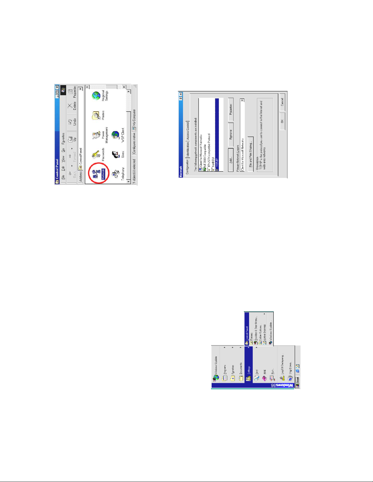
75
components list. If the TCP/IP is included, please process step 5. If it is not included,
please follow step 4 to install the TCP/IP.
z Click the NETWORK icon twice to enter the NETWORK setting windows.
z Click on the Configuration tag; check if the TCP/IC is included among the network
NOTE: When only one unit of the DVR is connected to a computer or LAN, you can
freely assign an IP address for the DVR. For example, there is a range of DVR IP
addresses from 192.168.0.1 to 192. 168.0.255. You can pick one for use from the
range of the IP. It’s not necessary to set MASK and G ATEWAY; leave the settings
as default.
74
your netw ork architecture. If you have any questions regarding those settings,
When a DVR is connected to a WAN, you must acquire a unique, permanent IP
address and correctly configure the MASK and GATEWAY settings according to
please contact a qualified MIS professional or your ISP.
IP, which must be in the same class type as your network address. IP addresses
are written as four sets of numbers separated by periods; for exa mple,
NOTE: When connecting to a network, each connected DVR must be assigned a unique
192.168.0.1 Therefore, if the connected network is identified as Class C, for
example, the first three sets of numbers of the DVR IP address must be the same
as the network address. If the connected network is identified as Class B, the
first two sets of numbers of the DVR IP address must be the same as the
network address. If you have any questions regarding these settings, please
contact a qualified MIS professional or your ISP.
z Click the Start Menu from your com puter, and point to the Settings/Control panel.
12.3 TCP/IP Communication Software
Follow the instructions below to install the TCP/IP communication program into your computer.
Page 39

. Any
and type in the IP address
77
those of the other chosen PCs, but in the same class type
If you are using a DHCP server, please select Obtain an IP address automatically
of your PC. This IP address must be different from the DVR IP but in the same class type.
assigned IP address for the connected DVRs must be in the same class type as the server.
If there is no DHCP server, please select specify an IP address
NOTE: The IP address of a DVR in a network must be unique to itself as opposed to
12.6 Connection Testing
With the previous settings, follow the instructions below to ensure whether you have established
the connection successfully.
z Click Start Æ Programs Æ MS-DOS Prompt
** This IP is the DVR IP address that is assigned for the connected DVR in step 2.
z Type in ping 192.168.0.1 then Enter. (See the sample screen below)
12.4 TCP/IP installation
Æ
, and then click Properties.
During the installation, you will be requested to insert the windows CD-ROM. After
installation, the PC will be restarted.
z Click Start Æ Settings Æ Control Panel Æ Netw ork.
12.5 TCP/IP Configuration setting
connection works properly. If not, please contact your ISP provider.
z Before processing the DVR installation in a WAN, please make sure the Internet
z Select TCP/IP
76
Page 40

13. SPECIFICATIONS
Model Number VR-601 U VR-601 E
Image System NTSC PAL
720 x 288 pixels
720 x 240 pixels
Resolution
ips (352x288)
50
352 x 288 pixels
352 x 240 pixels
Video In Composite Video In (BNC) x 1, Multiplexer Monitor In (BNC) x 1
Video Out Composite Video Out (BNC) x 1, Multiplexer Monitor Out (BNC) x 1
Audio In/Out Line In / Out (RCAx2), 16 bits, 8 kHz
Storage Media 80 GB (can be increased up to 240 GB)
Compression MJPEG
25 ips (720x288)
ips (352x240)
60
30 ips (720x240)
Memory Card SD Card
Archive Hot Swappable Removable HD
Image Size Best(48KB) / High(32KB) / Standard(21KB) / Basic(16KB)
Watermark Digital Signature
Recording Rate
Recording Mode Schedule / Manual / Alarm / Circular
Alarm Recording Event / Pre-Alarm / Post Alarm
Pre-Alarm Recording 100 pictures
Playback Speeds Frame Stepping, 1/16x,1/8x,1/4x,1/2x,1x,2x,4x,8x,16x,30x,100x
Record Search Alarm / Time / Event list / Filter( thumbnail) / SD card
Set-up Menu Multi-layer / Network setting
Log list 2000 records
Alarm In/Out 1 Alarm Input / Output
Key x 2
CD-R x 1
Power cord x 1
AC Adapter x 1
Instruction manual x 1
Remote live or recorded images
Archive image as JPEG formats,
Multi-brand multiplexer decoding,
Built-in Buzzer Yes
Communication Port RS-232, RS-485, and Ethernet Port
Network Interface Ethernet (RJ-45 10/100 base-Tx) x 1
Network Protocol TCP/IP, DHCP, HTTP, UDP, FT P, PPP
Software Upgrade Upgrade via Memory Card(SD Card) or RS-232
Password Protection Operation / Menu Setup / Remote Access
Network Capabilities
Power Supply (AC adapter) Input: 100V-240V, 50 Hz/60 Hz; Output: DC12V max 5A
5шC ~ 40шC (41шF ~ 104шF)
Screw ( #6-32UNC ) x 4(see P.56), Screw ( M3 ) x 8(not in use)
*Design and specifications subject to change without notice.
Dimensions 220 mm x 94 mm x 340 mm EIA 19" 2U Half Size Mountable
Weight About 3.9 kg
Operation Temperature
Regulation FCC, CE
Provided Accessories
79
successfully established. Please re-check all the hardware and software installation by
z If you receive a response as in the sample screen below, the connection hasn’t been
78
repeating steps 1 to 5. If you still can’t establish the connection after rechecking, please
contact your dealer.
connection.
z If you receive a response as in the sample screen below, you have successfully made the
Page 41

Decode on
VIEWER
Decode on
DVR
are not recommended for use with this product. For the latest updated list on the
recommended multiplexers, please contact your dealers or distributors.
80
14. Compatible Multiplexers
Manufacturer Model N/P Channel COLORS
Sensormatic RV2216 NTSC 16CH COLOR OK OK
GYYR DSP9C NTSC 9CH COLOR OK
ATV DPX 1 6 NTSC 16CH COLOR OK OK
ATV DPX 9 NTSC 9CH COLOR OK OK
PELCO MX4016CD NTSC 16CH COLOR OK OK
DM SPC2/D/N/04M NTSC 4CH COLOR OK OK
DM SLDX16C NTSC 16CH COLOR OK OK
ROBOT MV16 NTSC 16CH B/W OK
ROBOT MV96 NTSC 16CH COLOR OKOKIMPAC CBR-16CDT NTSC 16CH COLOR OK
JPI MP1600 NTSC 16CH COLOR OK
PAN ASONIC WJ-FS616 NTSC 16CH COLOR OK
PROVIDEO RMX-4CD NTSC 4CH COLOR OK
PROVIDEO RMX-16CD NTSC 16CH COLOR OK
ATV DPX 9 PAL 9CH COLOR OK OK
ATV DPX 1 6 PAL 16CH COLOR OK OK
PELCO MX4016CD-x PAL 16CH COLOR OK
ENEO VCMD-5016 PAL 16CH COLOR OK
KALATEL CBR-16eZX PAL 16CH COLOR OK
AVE MULTIview16CS PAL 16CH COLOR OK
SANYO MPX-CD92P PAL 9CH COLOR OK
NOTE: Multiplexers not shown on this list have not been tested by the engineering team and
SANYO MPX-CD163 PAL 16CH COLOR OK OK
Page 42

NetViewer
Inputting "URL Of Remote Device" (P.63)
PRECAUTIONS
Do not add extra “0” when inputting "URL Of Remote Device".
ª
(Ex. OK: 192.168.1.10, NG: 192.168.001.010)
NetViewer
Save a viewing image (P.66)
When performing successional saving images, the saving interval changes with the PC
ª
performance and the network environment.
Network Viewer
Change the Record Properties (P.67)
Please do not set up Alarm setting via the Network Viewer. If set up Alarm setting via the
When the Alarm Operation is ON, The image software (Network Viewer) doesn't show the pictures
ª
and a message will be displayed.
Network Viewer, please set up Pre-Alarm setting from MAIN MENU again. Because the
displayed setup may differ from an actual setup.
ª
Please do not extract the removable HDD or do not move this equipment for 15 seconds after
Handling of the HDD
ª
OPERATE OFF. It may cause a failure of the HDD.
Please read the followings before getting started:
The alarm recording is interrupted if the Video-Loss occurs during Alarm recording.
Alarm Recording (P.27)
Recording Operation
ª
Backup Operations
Mobile Rack HD Backup (P.35)
Please operate backup ( FULL / ALARM / SELECT ) exclude the 2.00MB files. Otherwise backup
ª
operation may not perform correctly.
The maximum number of the saving images into one SD Card is 500. Please operate SD Card
BACKUP Operations
SD Card Backup (P.37)
ª
Backup within the object file's name (F0xxx.jpg) do not exceed 500.
Please operate off and on after changing the IP address.
Menu Setup
Changing IP address (P.46)
ª
RS-232, RS-485 or NetViewer
Operate in the Key Lock mode (P.53, P.66)
The Playback picture reaches at the END of recorded data in HDD with key lock mode, it will
ª
continuously play back in short period near Data end and it will not stop. In such a case, please
send the "STOP" command.
When sending the "TIME SEARCH" command, please make sure to send the "STOP" command
RS-232 & RS-485
"TIME SEARCH" command (P.54)
ª
just before sending it.
 Loading...