

Page 1
R
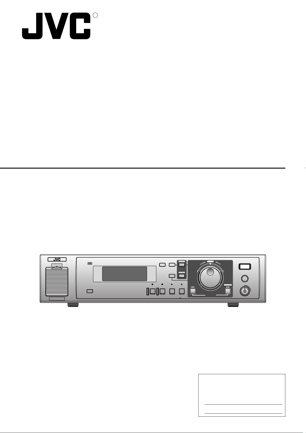
DIGITAL VIDEO RECORDER
VR-510U
POWER
WARNING
SLEEP
TIMER CANCEL
REC STOP PLAY STILL
DISPLAY
MENU
SEARCH
INSTRUCTIONS
DIGITAL VIDEO RECORDER VR-510U
E
C
L
T
E
S
REV FWD
SKIP/ALARM
SEARCH
EXECUTE
REC
CLOCK RESET/ CLEAR
OPE. LOCK
ON
For Customer Use:
Enter below the Serial No. which is
located on the rear of cabinet. Retain this
information for future reference.
Model No. VR-510U
Serial No.
LLT0010-001A
Page 2
1. Read all of these instructions.
2. Save these instructions for later use.
3. All warnings on the product and in the operating instructions should be adhered to.
4. Unplug this appliance system from the wall outlet before cleaning. Do not use liquid cleaners or aerosol cleaners. Use a damp
cloth for cleaning.
5. Do not use attachments not recommended by the appliance manufacturer as they may cause hazards.
6. Do not use this appliance near water – for example, near a bathtub, washbowl, kitchen sink, or laundry tub, in a wet basement,
or near a swimming pool, etc.
7. Do not place this appliance on an unstable cart, stand, or table. The appliance may fall, causing serious
injury to a child or adult, and serious damage to the appliance.
Use only with a cart or stand recommended by the manufacturer, or sold with the appliance.
Wall or shelf mounting should follow the manufacturer’s instructions, and should use a mounting kit
approved by the manufacturer.
An appliance and cart combination should be moved with care. Quick stops, excessive force, and uneven surfaces may cause the appliance and cart combination to overturn.
8. Slots and openings in the cabinet and the back or bottom are provided for ventilation, and to insure
reliable operation of the appliance and to protect it from overheating, these openings must not be blocked
or covered. The openings should never be blocked by placing the appliance on a bed, sofa, rug, or other similar surface. This
appliance should never be placed near or over a radiator or heat register. This appliance should not be placed in a built-in
installation such as a bookcase unless proper ventilation is provided.
9. This appliance should be operated only from the type of power source indicated on the marking label. If you are not sure of the
type of power supplied to your home, consult your dealer or local power company. For appliance designed to operate from
battery power, refer to the operating instructions.
10. This appliance system is equipped with a 3-wire grounding type plug (a plug having a third (grounding) pin). This plug will only
fit into a grounding-type power outlet. This is a safety feature. If you are unable to insert the plug into the outlet, contact your
electrician to replace your obsolete outlet. Do not defeat the safety purpose of the grounding plug.
11. For added protection for this product during a lightning storm, or when it is left unattended and unused for long periods of time,
unplug it from the wall outlet and disconnect the antenna or cable system. This will prevent damage to the product due to
lightning and power-line surges.
12. Do not allow anything to rest on the power cord. Do not locate this appliance where the cord will be abused by persons walking
on it.
13. Follow all warnings and instructions marked on the appliance.
14. Do not overload wall outlets and extension cords as this can result in fire or electric shock.
15. Never push objects of any kind into this appliance through cabinet slots as they may touch dangerous voltage points or short
out parts that could result in a fire or electric shock. Never spill liquid of any kind on the appliance.
16. Do not attempt to service this appliance yourself as opening or removing covers may expose you to dangerous voltage or
other hazards. Refer all servicing to qualified service personnel.
17. Unplug this appliance from the wall outlet and refer servicing to qualified service personnel under the following conditions:
a. When the power cord or plug is damaged or frayed.
b. If liquid has been spilled into the appliance.
c. If the appliance has been exposed to rain or water.
d. If the appliance does not operate normally by following the operating instructions. Adjust only those controls that are
covered by the operating instructions as improper adjustment of other controls may result in damage and will often require
extensive work by a qualified technician to restore the appliance to normal operation.
e. If the appliance has been dropped or the cabinet has been damaged.
f. When the appliance exhibits a distinct change in performance – this indicates a need for service.
18. When replacement parts are required, be sure the service technician has used replacement parts specified by the manufacturer that have the same characteristics as the original part. Unauthorized substitutions may result in fire, electric shock, or
other hazards.
19. Upon completion of any service or repairs to this appliance, ask the service technician to perform routine safety checks to
determine that the appliance is in safe operating condition.
2
Page 3
SAFETY PRECAUTIONS
CAUTION ATTENTION
RISK OF ELECTRIC SHOCK
DO NOT OPEN
CAUTION: TO REDUCE THE RISK OF ELECTRIC SHOCK,
WARNING:
TO REDUCE THE RISK OF FIRE OR ELECTRIC
SHOCK, DO NOT EXPOSE THIS APPLIANCE TO
RAIN OR MOISTURE.
This unit should be used with 120 V AC only.
CAUTION:
To prevent electric shocks and fire hazards, DO NOT
use any other power source.
NOTE:
The rating plate (serial number plate) is on the bottom of the unit.
INFORMATION
This equipment has been tested and found to comply with the
limits for a Class B digital device, pursuant to Part 15 of the
FCC Rules. These limits are designed to provide reasonable
protection against harmful interference in a residential installation. This equipment generates, uses, and can radiate radio
frequency energy and, if not installed and used in accordance
with the instructions, may cause harmful interference to radio
communications. However, there is no guarantee that interference will not occur in a particular installation.
If this equipment does cause harmful interference to radio or
television reception, which can be determined by turning the
equipment off and on, the user is encouraged to try to correct
the interference by one or more of the following measures:
● Reorient or relocate the receiving antenna.
● Increase the separation between the equipment and receiver.
● Connect the equipment into an outlet on a circuit different
from that to which the receiver is connected.
● Consult the dealer or an experienced radio/TV technician for
help.
CAUTION
CHANGES OR MODIFICATIONS NOT APPROVED BY JVC
COULD VOID USER’S AUTHORITY TO OPERATE THE
EQUIPMENT.
THIS DEVICE COMPLIES WITH PART 15 OF THE FCC
RULES. OPERATION IS SUBJECT TO THE FOLLOWING
TWO CONDITIONS: (1) THIS DEVICE MAY NOT CAUSE
HARMFUL INTERFERENCE, AND (2) THIS DEVICE MUST
ACCEPT ANY INTERFERENCE RECEIVED, INCLUDING
INTERFERENCE THAT MAY CAUSE UNDESIRED OPERATION.
DO NOT REMOVE COVER (OR BACK).
NO USER-SERVICEABLE PARTS INSIDE.
REFER SERVICING TO QUALIFIED SERVICE PERSONNEL
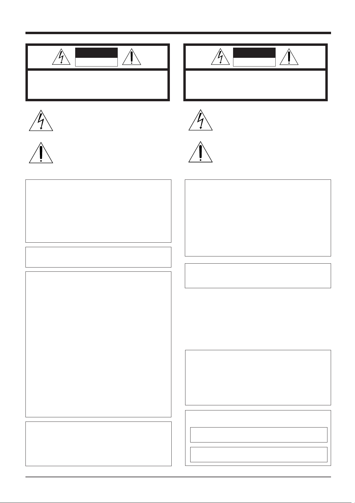
The lightning flash with arrowhead symbol, within an
equilateral triangle, is intended to alert the user to the
presence of uninsulated “dangerous voltage” within the
product’s enclosure that may be of sufficient magnitude
to constitute a risk of electric shock to persons.
The exclamation point within an equilateral triangle is
intended to alert the user to the presence of important
operating and maintenance (servicing) instructions in
the literature accompanying the appliance.
RISQUE D’ELECTROCUTION
NE PAS OUVRIR
ATTENTION: POUR EVITER TOUT RISQUE D’ELECTROCUTION
SE REFERER A UN AGENT QUALIFIE EN CAS DE PROBLEME.
NE PAS OUVRIR LE BOITER.
AUCUNE PIECE INTERIEURE N’EST
A REGLER PAR L’UTILISATEUR.
Le symbole de l’éclair à l’intérieur d’un triangle
équilatéral est destiné à alerter l’utilisateur sur la
présence d’une “tension dangereuse” non isolée dans
le boîtier du produit. Cette tension est suffisante pour
provoquer l’électrocution de personnes.
Le point d’exclamation à l’ intérieur d’un triangle
équilatéral est destiné à alerter l’utilisateur sur la
présence d’opérations d’entretien importantes au sujet
desquelles des renseignements se trouvent dans le
manuel d’instructions.
*Ces symboles ne sont utilisés qu’aux Etats-Unis.
AVERTISSEMENT:
POUR EVITER LES RISQUES D’INCENDIE OU
D’ELECTROCUTION, NE PAS EXPOSER
L’APPAREIL A L’HUMIDITE OU A LA PLUIE.
Ce magnétoscope ne doit être utilisé que sur du
courant alternatif en 120 V.
ATTENTION:
Afin d’éviter tout resque d’incendie ou
d’électrocution, ne pas utiliser d’autres sources
d’alimentation électrique.
REMARQUE:
La plaque d’identification (numéro de série) se trouve sur le
panneau arrière de l’appareil.
WARNING ON LITHIUM BATTERY
The battery used in this device may present a fire or chemical
burn hazard if mistreated. Do not recharge, disassemble, heat
above 100˚C (212˚F) or incinerate.
Replace battery with Matsushita Electric CR2032, use of
another battery may present a risk of fire or explosion.
• Dispose of used battery promptly.
• Keep away from children.
• Do not disassemble and do not dispose of in fire.
INFORMATION (FOR CANADA)
RENSEIGNEMENT (POUR CANADA)
This Class B digital apparatus complies with Canadian ICES-
003.
Cet appareil numérique de la Class B est conforme à la
norme NMB-003 du Canada.
3
Page 4

Thank you for purchasing the JVC
VR-510U digital video recorder.
CONTENTS
1. INTRODUCTIONS
1-1 Precautions .................................................................5
2. CONTROLS, CONNECTIONS AND DISPLAY
2-1 Front panel ..................................................................6
2-2 Rear panel .................................................................. 7
2-3 Display ........................................................................8
3. CONNECTIONS
3-1 Recording video signals from a camera .....................9
3-2 Connecting more than one camera (using an external
switcher).................................................................... 10
3-3 Connecting signal input/output terminals .................. 11
4. PREPARATION
4-1 Installing a battery ..................................................... 12
4-2 Power supply ............................................................ 12
4-3 Setting the date and time ..........................................13
4-4 Daylight-saving time compensation .......................... 13
5. ON-SCREEN DISPLAY/MENU SWITCHES
5-1 On-screen display .....................................................14
5-2 Menu switches .......................................................... 15
Menu flow................................................................. 15
Jog/shuttle dial operation ..........................................16
Display ...................................................................... 17
Setting ....................................................................... 18
5-3 Menu switch details .................................................. 19
6. RECORDING
6-1 Basic operation ......................................................... 22
Recording system
<Normal recording> <Repeat recording> ................. 22
6-2 Program timer recording ........................................... 23
Weekly timer ............................................................. 23
Timer-recording for 24 hours or more .......................24
Daily timer .................................................................25
Estimated recordable duration ..................................26
6-3 Holiday timer recording ............................................. 27
6-4 Alarm recording ......................................................... 28
Repeat recording during alarm recording ................. 28
6-5 Sensor recording ...................................................... 29
Pre-sensor recording ................................................ 29
6-6 Recording with an external activation signal .............30
6-7 Automatic restart of recording after power failure ..... 30
7. PLAYBACK AND SPECIAL-EFFECTS PLAYBACK
7-1 Basic operation ......................................................... 31
Playback ................................................................... 31
Simultaneous Playback mode .................................. 31
7-2 Jog/shuttle playback ................................................. 32
7-3 Skip search ............................................................... 33
Time search .............................................................. 33
Event search .............................................................34
Alarm search ............................................................. 34
7-4 Alarm or day/time direct search ................................. 35
8. HARD DISK CONTROL
8-1 Hard disk maintenance ............................................. 36
Scanning the disk ..................................................... 36
Formatting ................................................................. 37
9. TROUBLESHOOTING
9-1 Error indication ......................................................... 38
9-2 No error indication .................................................... 39
10. RS-232C INTERFACE
10-1 Specifications .......................................................... 40
10-2 Protocols and commands ........................................40
10-3 Commands .............................................................. 42
11. OTHERS
11-1 Recording time ....................................................... 47
11-2 Signal input/output terminals ...................................48
11-3 Specifications .......................................................... 49
4
Page 5

1 INTRODUCTION
Major features
● Large-capacity hard disk (80 GB)
Large-capacity hard disk enables high-quality/high-capacity
recording/playback. (Can be increased up to 160 GB)
● Simultaneous recording/playback mode
You can play or back up programs even during recording.
● Instant picture search
You can access images at a specified date/time or alarm
point instantly.
● Restoring recording after power failure
When power is restored after power failure, recording
automatically re-starts in the same mode engaged before
the power failure.
● Timer recording function
Up to 8 timer recording settings can be programmed,
including daily and weekly.
● Alarm recording function
You can preset the VCR to automatically enter a specified
recording mode whenever an alarm signal is received.
● RS-232C control
JVC cannot accept liability for loss or damage to recording
that result from a malfunction of this unit or the hard drive.
Please note that it may be unlawful to use any material
recorded from television broadcast programs or prerecorded programs without the consent of the owner of
copyright, except in cases where the material is recorded
exclusively for personal use.
When the hard disk is replaced or the firmware is upgraded, all recorded data on the hard disk is erased.
Characters and marks used in this text
Caution : Additional information about a specific
operation or procedure.
Memo : Information about a function or specification.
Reference : Other items or pages containing information
on the topic.
1-1 Precautions
Installation and storage
● To avoid malfunctions or damage to your recorder, do
not use or store it in places subject to the following
conditions.
•Extreme heat or cold – temperature outside the allowable
range (5˚C to 40˚C)
•High humidity – outside the allowable operating range
(30% to 80%)
•Strong magnetic fields (generated by transformers,
motors, etc.)
•Electrical waves generated by equipment such as a
transceiver or cellular phone
•Dust and soil
•Vibrations
•Condensation
Handling
To prevent unit from overheating, do not place it anything
on top of any other equipment or place other equipment on
top of it.
This unit should only be operated when it is in a horizontal
(flat) position.
Avoid violent shocks to the unit.
Do not move this unit when the power is ON. This could
cause it to malfunction.
To avoid a malfunction, do not place anything heavy such
as a TV monitor on this unit.
To clean this unit, wipe it gently with a soft cloth.
Do not use chemical solvents such as thinner or benzene
to clean this unit. Doing so could damage the surface. To
remove any excessive dirt, wipe the unit with a cloth dipped
in detergent and then wipe it with a dry cloth.
Transportation
Do not apply a shock to this unit during transportation. Do
not move this unit during recording or playback.
Energy saving
When the unit is not going to be used for a long time, turn
the power off to avoid unnecessary power consumption.
Hard disk
The hard disk is a consumable item. Replacement is
recommended after 30,000 hours of use (if used in a 25˚C
environment). For information on maintenance planning
and costs, consult your nearest JVC dealer.
5
Page 6
2 CONTROLS, CONNECTIONS AND DISPLAY
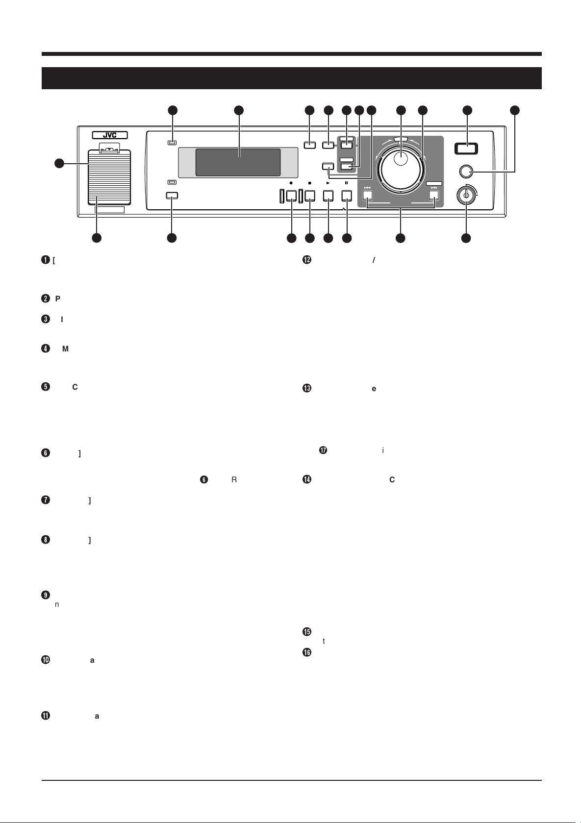
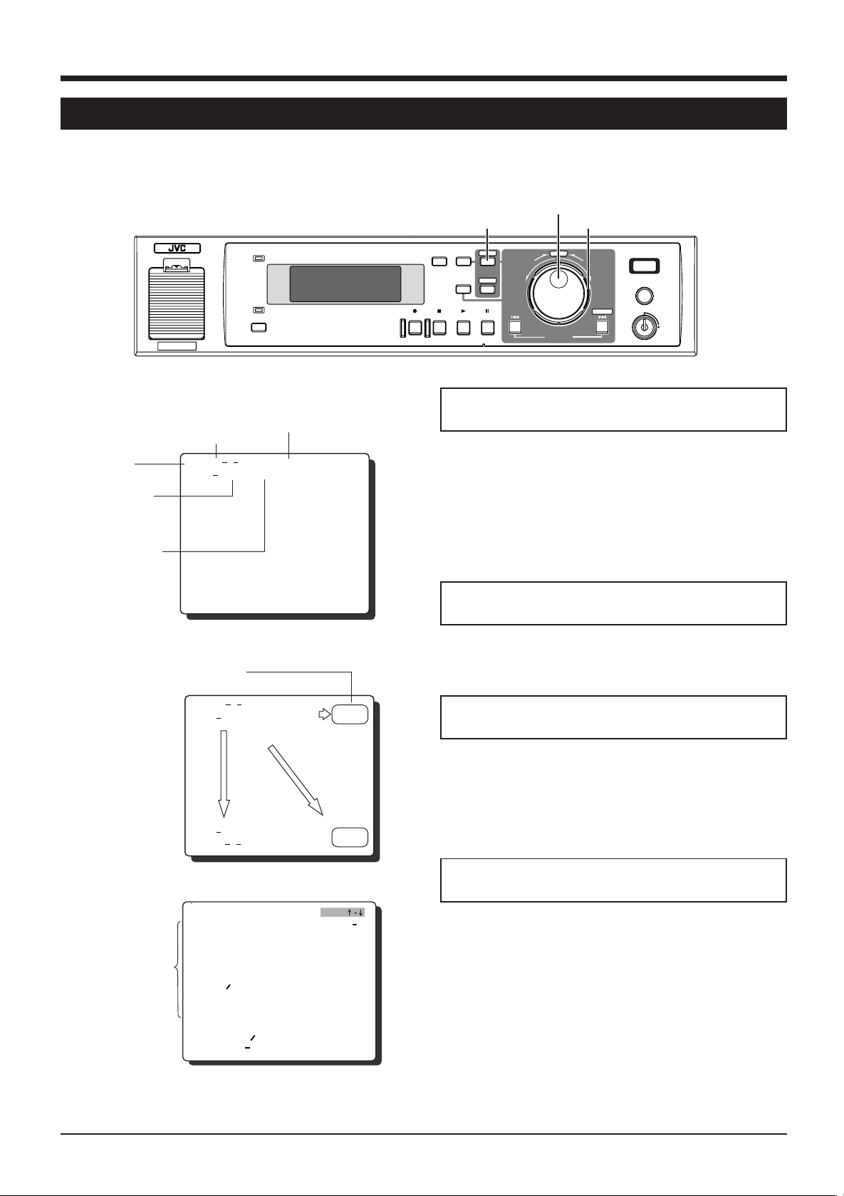
2-1 Front panel
2
POWER
WARNING
3
1
SLEEP
* Behind
1920
the cover
1
[LITHIUM BATTERY] battery box for memory backup
Install a memory backup battery. When replacing the battery with
a new one, be sure to set the date/time again.
Reference: “4-1 Installing a battery” on page 12.
2
[POWER] indicator
When the [POWER] switch is turned ON, this indicator lights.
3
[DISPLAY PANEL]
Shows the operation status or setting details.
Reference: “2-3 Display” on page 8.
4
[TIMER] button
After programming the timer, press this button to engage the
Standby mode.
Reference: “6-2 Program timer recording” on page 23.
5
[CANCEL] button
• When a line is selected on the [PROGRAM TIMER] or
[HOLIDAY SET] screen, press this button to clear it.
• When an alarm or warning occurs, press this button to stop the
buzzer.
Reference: “6-2 Program timer recording” on page 26 and “6-4
Alarm recording” on page 28
6
[MENU] button
Press this button in the Stop mode to display the main menu
setting screen.
* The menu cannot be displayed when the 6 [TIMER] indicator
(see page 8) is on or during recording/playback.
7
[SEARCH] button
Press to display the search menu for alarm search or time/date
search. Pressing this button again restores the normal screen.
Reference: “7-4 Alarm or day/time direct search” on page 35.
8
[DISPLAY] display panel switching button
Each time this button is pressed, the display changes in order from
CLOCK to DATE to REMAIN to REC QUALITY-REC SPEED.
• Press [DISPLAY] button in any mode except Record for about 2
seconds. The recording setting display is displayed, allowing
you to set recording quality/number of frames.
9
Jog dial
In the Play or Still mode, use this dial for frame-by-frame
playback.
Reference: “7-2 Jog/shuttle playback” on page 32.
With the menu/search screen, use this dial to set the item or
value.
Reference: “Jog/shuttle dial operation” on page 16.
0
Shuttle search dial
Turn to vary the playback speed in the Play or Still mode.
Reference: “7-2 Jog/shuttle playback” on page 32.
With the menu/search screen, use this dial to set the item or
value.
Reference: “Jog/shuttle dial operation” on page 16.
!
[REC] indicator
Lights when recording on the hard disk.
Blinks during alarm/sensor recording.
Goes out during recording if you set <REC TALLY> of <FRONT
DISPLAY> to “OFF”.
Reference: “5-3 Menu switch details” on page 19.
456
TIMER CANCEL
DISPLAY
REC STOP PLAY STILL
@
[CLOCK RESET/CLEAR] button
7 8
MENU
REV FWD
SEARCH
15161718
10 11
9
DIGITAL VIDEO RECORDER VR-510U
E
C
L
T
E
S
REC
CLOCK RESET/ CLEAR
OPE. LOCK
13
SKIP/ALARM
SEARCH
14
EXECUTE
ON
In the Stop mode, press this button together with the [STOP]
button to reset the second value on the internal clock.
• With 29 seconds or less, the minute value stays the same and
the second value is reset to 00.
• With 30 seconds or more, the minute value is increased by 1
and the second value is reset to 00.
Pressing this button stops recording during alarm/sensor
recording.
When the alarm list screen or power-off list screen is displayed,
pressing this button clears the list.
Reference: “7-4 Alarm or day/time direct search” on page 35.
Use this button to cancel the [AUTO SCAN DISK] function.
Reference: “8-1 Hard disk maintenance” on page 36.
#
[OPE.LOCK] operation lock key
Set to “ON” position with the provided key to lock switch
operation.
Security levels can be selected with menu switch <OPERATION
LOCK MODE>.
● ALL: Locks all switches.
● REC STOP: Prevents recording from being stopped when the
&
[STOP] button is pressed.
* Set to “ALL” for timer recording.
Reference: “5-3 Menu switch details” on page 19.
$
[SKIP/ALARM SEARCH·EXECUTE] SKIP SEARCH·EXECUTE
button
Skip search
In the Stop mode, press this button to go to the start or end of a
recording of the hard disk.
In the Play mode, press this button to start skip search.
There are three types of skip search:
● Time search: Goes to the point a specified time from the
current point.
● Event search: Goes to the start of an event recording.
● Alarm search: Goes to the start of an alarm recording.
Reference: “7-3 Skip search” on page 33
EXECUTE button
Use this button to execute alarm direct search, day/time direct
search or “disk scan”/ “quick format”.
Reference: “7-4 Alarm or day/time direct search” on page 35 and
“8-1 Hard disk maintenance” on page 36
%
[STILL] button
In the Play mode, press this button to engage the Still mode.
^
[PLAY] button
Press this button to start playback.
● In the Stop mode: Playback starts at the position where
playback was last stopped.
* Just after the power is turned ON, playback starts from a point
about 5 seconds before the end point of the last recording.
● In the Record mode: Simultaneous Playback mode is
engaged.
Reference: “Simultaneous Playback mode” on page 31.
12
6
Page 7
2 CONTROLS, CONNECTIONS AND DISPLAY (contd.)
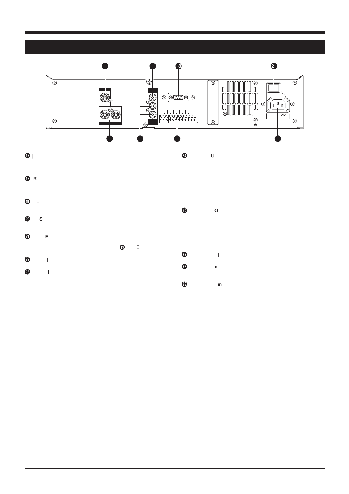
2-2 Rear panel
26
CAMERA IN
1
12
MONITOR OUT
&
[STOP] button
Press this button to stop operation. In the Simultaneous
Playback mode, press this button to stop playback and engage
the normal recording mode.
*
[REC] button
Press in the Stop mode to start recording. The recording mode
can be set with the menu switch.
Reference: “6-1 Basic operation” on page 22.
(
[SLEEP] button
Before turning the power OFF, press this button to stop the
rotation of the hard disk.
)
[SYSTEM RESET] button
This button is used for servicing. Normally, you do not need to
use this button.
q
[POWER] switch
Turns power ON/OFF.
* Before turning the power OFF, press the ( [SLEEP] button to
stop the rotation of the hard disk.
w
[AC IN] socket
Connect to an AC 120 V outlet using the provided power cable.
e
Signal input/output terminal
CAM SW OUT
Outputs camera switch timing control signals when this unit is
connected to a frame switcher.
Reference: "3-2 Connecting more than one camera (using an
external switcher)" on page 10.
ALARM IN 1
Accepts signals to start alarm or sensor recording.
ALARM RESET
Accepts signals to stop recording during alarm or sensor
recording.
CLOCK RESET IN
Connect to a master clock or the [CLOCK RESET
OUT] terminal of another device. When a clock reset
signal is input, this unit can be set to the master clock
or the other device’s clock.
When the clock reset signal is input, the clock second
value is reset: .
● With 29 seconds or less, the minute value stays the same
and the second value is reset to 00.
● With 30 seconds or more, the minute value is increased by 1
and the second value is reset to 00.
CLOCK RESET OUT
Outputs a clock reset signal when the internal clock is 00:00
or 12:00.
EXT REC IN
Recording is automatically activated by an external signal
when menu switch <REC MODE> of <EXT MODE> is set to
“TRIG” or “MANUAL”.
Reference: “5-3 Menu switch details” on page 20.
HDD FULL OUT
Outputs a signal during recording when the hard disk’s
available space is 0% except in the following cases.
● Menu switch <HDD FULL OUT> set to “OFF”
● Menu switch <REPEAT REC> set to “ALL”
Reference: “5-3 Menu switch details” on page 20.
AUDIO
AUDIO
27
IN
OUT
1
CAM SW
ALARM
OUT
2
COM COM
IN1
SPARE SPARE
SPARE
28
RS-232C
ALARM
RESET
CLOCK
RESET IN
CLOCK
RESET OUT
REC IN
EXT
HDD
FULL OUT
SIGNAL GND
21
POWER
ON OFF
I
O
AC IN 120 V
50 Hz / 60 Hz
222325 24
r
[AUDIO OUT] audio output connector
Outputs recorded audio during playback.
In the Record or Stop mode, outputs the input audio signal.
Audio is not output in the following cases.
● When playing back signals recorded with menu switch <REC
SPEED> set to “1/5” or “1/10”
● In the Frame-by-Frame Playback, Still or Search mode
● When playing back signals recorded with menu switch <AUDIO
REC> set to “OFF”
● When the menu is displayed
t
[MONITOR OUT] monitor output connector
Outputs video signals recorded on the hard disk in the Play
mode. In the Record mode, outputs video input signals from the
camera or frame switcher connected to the [CAMERA IN]
connector.
The picture signal from the [CAMERA IN] connector is output
through the [MONITOR OUT] connector even when the power is
turned OFF.
y
[CAMERA IN] camera input connector
Connect to a camera.
u
[AUDIO IN] audio input connector
Connect to the audio output connector of the audio source
device.
i
[RS-232C] remote connector
Connect a personal computer or compatible control unit for
external remote operation.
Reference: “10. RS-232C INTERFACE” on page 40.
7
Page 8
2 CONTROLS, CONNECTIONS AND DISPLAY (contd.)
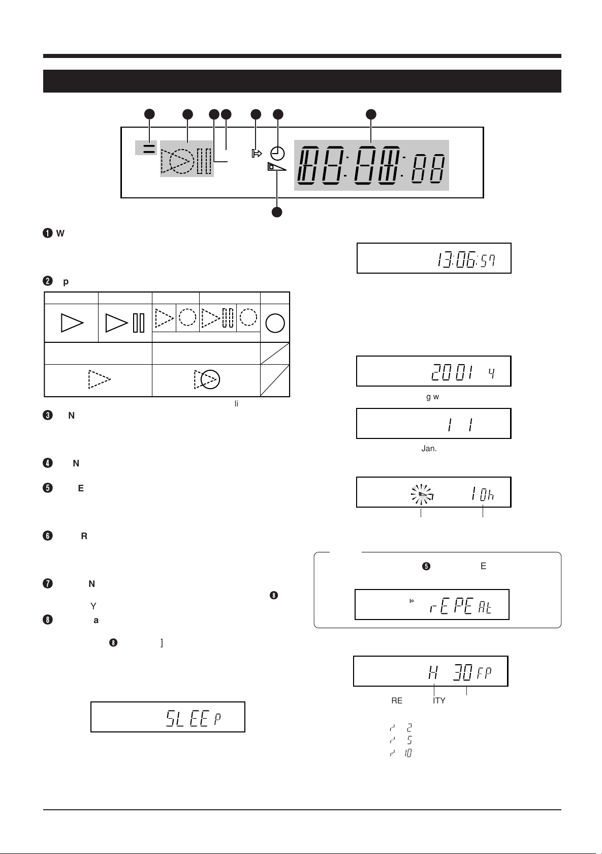
2-3 Display
1
WARNING indication
1
2 4 5 6 8
3
VN
S
Blinks when there is a problem with input signals, fan
motor or hard disk, as well as when the battery is low.
Reference: “9-1 Error indication” on page 38.
2
Operation mode indication
Play Still
Search or Slow Motion play
3
SENSOR ON indication
Simultaneous play
Blinks alternately
Simultaneous search or
simultaneous Slow Motion play
Simultaneous still
* Dotted line mark blinks
Lights when menu switch <REC MODE> of <ALARM/
SENSOR MODE> is set to “SENSOR”.
Reference: “6-5 Sensor recording” on page 29.
4
[MENU, SEARCH SET] indication
Lights during menu operation or search setting.
5
[REPEAT REC] indication
Lights when repeat recording is set.
Reference: "5-3 Menu switch details" on page 20 and
“6-1 Basic operation” on page 22.
6
[TIMER] indication
Lights in the Timer Record Standby mode or during timer
recording.
Reference: “6-2 Program timer recording” on page 23.
7
[REMAIN] indication
Lights when the remaining time is displayed (refer to
[DISPLAY] button on page 6 for more details).
8
Counter and function display
The counter is displayed in the Play or Record mode.
Pressing the 8 [DISPLAY] button on the front panel (see
page 6) switches the display consecutively through
CLOCK, DAY, REMAIN and REC QUALITY•REC SPEED.
7
Record
8
CLOCK display
VN
S
Displays the time.
During playback, the approximate time of the recording is
displayed. Accuracy of the display time varies depending
on the recording speed.
Reference: “4-3 Setting the date and time” on page 13.
DAY display
VN
S
Switching with 1-second interval.
VN
S
e.g.: Jan. 1, 2001 is displayed.
REMAIN TIME display
VN
S
Lights
Remaining time
Displays the remaining recording time.
Memo:
• If REPEAT REC is set, 5 [REPEAT REC] and “RE-
PEAT” are displayed. Remaining time is not displayed.
VN
S
REC QUALITY·REC SPEED display
VN
S
SLEEP display
VN
S
When the [SLEEP] button is pressed, the hard disk
stops rotating and “SLEEP” is displayed.
* When the Record mode is engaged from the Sleep mode,
the hard disk has to warm up before recording can start. No
images will be recorded during this period.
8
REC QUALITY
REC SPEED
* The 1/2, 1/5 and 1/10 frame are shown as below.
1/2 frame:
1/5 frame:
1/10 frame:
Reference: DVR MODE in “5-3 Menu switch details” on
page 19.
Page 9
3 CONNECTIONS
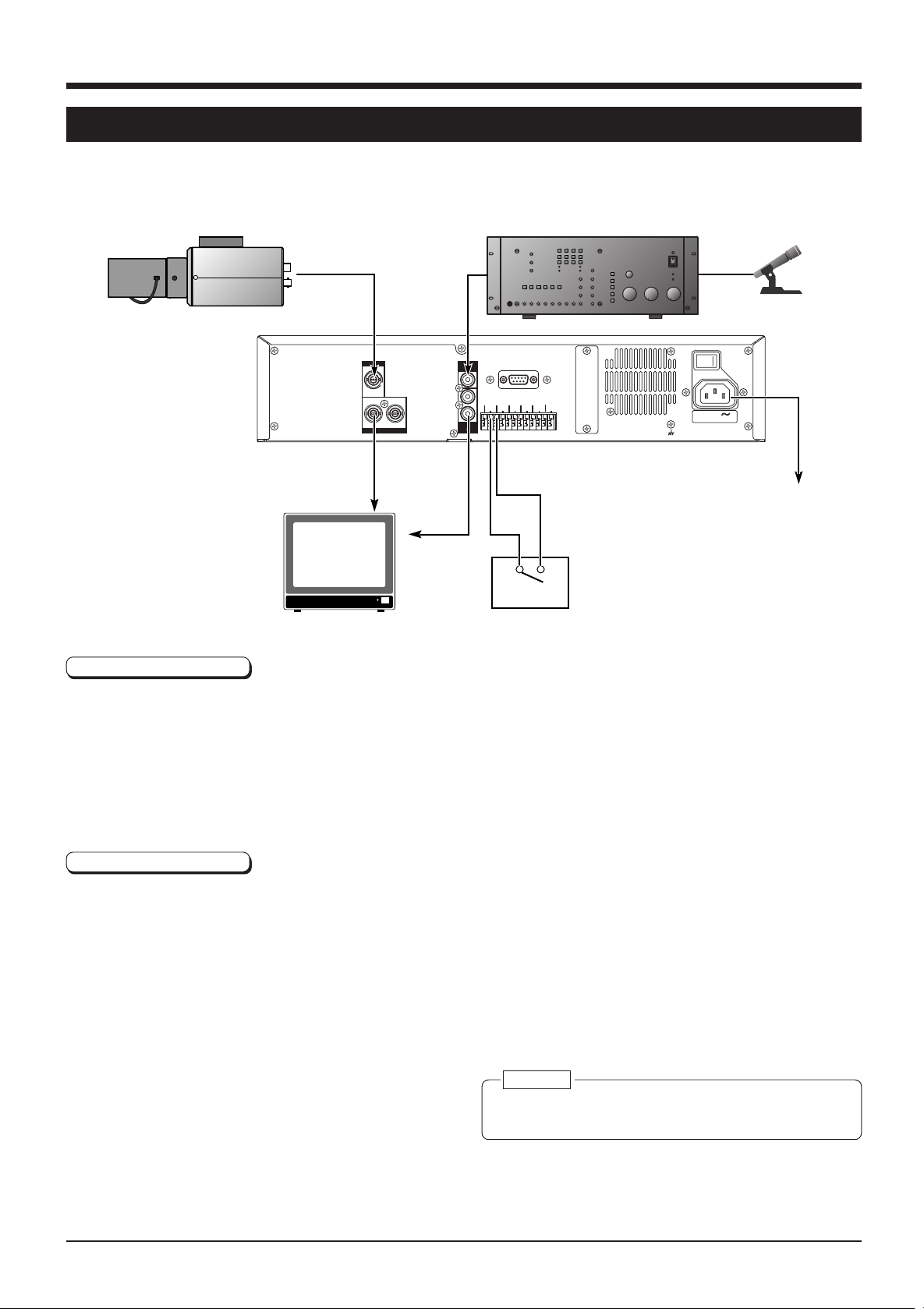
3-1 Recording video signals from a camera
This section describes how to connect a camera and record camera signals. When more than one camera is connected, the
cameras must be synchronized. Multi-camera connections are discussed in the next section.
Video camera
Connecting a camera
Monitor
CAMERA IN
1
12
MONITOR OUT
AUDIO
AUDIO
OUT
IN
1
2
CAM SW
OUT
COM COM
RS-232C
ALARM
ALARM
CLOCK
IN1
EXT
RESET
RESET IN
REC IN
SPARE
SPARE
HDD
CLOCK
SPARE
FULL OUT
RESET OUT
ALARM IN
COM
Alarm sensor
Amplifier
SIGNAL GND
POWER
ON OFF
I
O
AC IN 120 V
50 Hz / 60 Hz
Microphone
Provided
power cable
To AC 120 V, 50 Hz/
60 Hz
1. Connect the [MONITOR OUT] and [AUDIO OUT] connectors to the monitor’s video and audio connectors.
2. Connect [CAMERA IN] connector to the video camera’s video output connector.
3. To record sound, connect a microphone amplifier to the [AUDIO IN] connector.
4. To record an alarm, connect the alarm sensor to the [ALARM IN 1] and [COM] signal input/output terminals.
5. After all connections are complete, connect the power cable to the [AC IN] socket and connect the plug to an AC 120 V outlet.
6. Turn ON all connected equipment, then turn the [POWER] switch on the rear panel to ON.
Menu switch setting
Example of settings when using an alarm sensor and recording audio.
DVR MODE
[REC QUALITY] set to “N”
[REC SPEED] set to “30”
[AUDIO REC] set to “ON”
ALARM/SENSOR MODE
[REC MODE] set to “ALARM”
Reference: “5-3 Menu switch details” on page 19.
Caution:
● Before connecting or disconnecting any equipment,
turn the power of all connected equipment OFF.
9
Page 10
3 CONNECTIONS (contd.)
CAMERA IN
MONITOR OUT
1
1
2
12
AUDIO
IN
AUDIO
OUT
RS-232C
POWER
SIGNAL GND
CAM SW
OUT
ALARM
IN1
SPARE SPARE
SPARE
HDD
FULL OUT
ALARM
RESET
CLOCK
RESET IN
CLOCK
RESET OUT
EXT
REC IN
COM COM
ON OFF
I
O
AC IN 120 V
50 Hz / 60 Hz
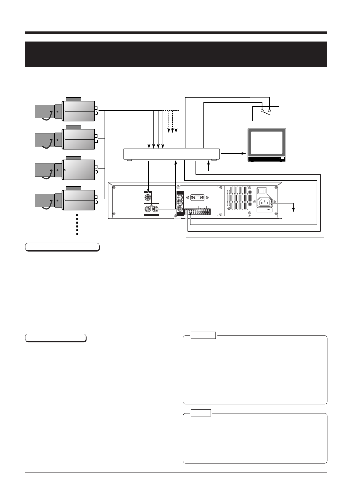
3-2 Connecting more than one camera (using an external
switcher)
When an external switcher is connected to the [CAMERA IN] connector of this unit, images from multiple cameras can be
recorded. Select the camera image with the switcher.
● For a connectable multiplexer (switcher), consult your JVC dealer.
Video camera
Video camera
Alarm sensor
Video camera
Switcher
VTR OUT
COM
VTR IN
ALARM IN
VTR TRIGGER IN
COM
Monitor
ALARM OUT
Video camera
Provided
power cable
To AC 120 V,
ALARM IN
50 Hz/60 Hz
COM
CAM SW OUT
Connection procedures
1.Connect the video output connector of the frame switcher to the video input connector of the monitor.
2.Connect the camera to the [CAMERA IN] connector of the frame switcher.
* For camera connections, refer to the frame switcher’s instructions.
3.Connect the frame switcher’s [VTR OUT] connector to the [CAMERA IN] connector of this unit.
4.Connect the [MONITOR OUT] connector of this unit to the frame switcher’s [VTR IN] connector.
5.Connect the alarm sensor to the frame switcher.
6.Connect the frame switcher’s [VTR TRIGGER] and [ALARM OUT] signal input/output terminals to the [CAM SW OUT] and
[ALARM IN 1] terminals of this unit.
7.After all connections are complete, connect the power cable to the [AC IN] socket and connect the plug to an AC 120 V outlet.
8.Turn ON all connected equipment, then turn the [POWER] switch on the rear panel to ON.
Menu switch setting
Example of settings when alarm recording is performed
using an external switcher.
DVR MODE
[REC QUALITY] set to “N”
[EXT SWITCHER] set to “ON”
ALARM/SENSOR MODE
[REC MODE] set to “ALARM”
[REC DURATION] set to “MANUAL” when the alarm
time is set with the switcher
This unit continues recording for about 5 seconds
after the alarm duration set with the switcher has
passed.
Reference: “5-3 Menu switch details” on page 19.
10
Caution:
● Before connecting or disconnecting any equipment,
turn the power of all connected equipment OFF.
● When a field switcher is used, picture quality will be
degraded if [REC QUALITY] is set to "H". In some
cases, the specified camera may not be used or the
playback picture may move up and down.
● As the camera switching signal is recorded, the picture
on the lower section of the monitor screen may be
missing. To record the external switcher’s on-screen
display, set the display to the upper section of the screen.
Memo:
● Select the camera with the switcher.
● The monitor picture may not be switched during jog/
shuttle operation and skip search operation. This is
because the playback camera number is different from
the camera number selected with the switcher. To
display the picture from the selected camera on the
monitor, press the [PLAY] button.
Page 11
3 CONNECTIONS (contd.)
COM
HDD FULL
OUT
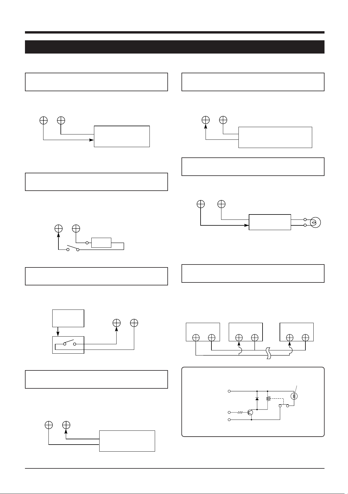
3-3 Connecting signal input/output terminals
[CAM SW OUT] camera switching signal
output terminal
To control the camera switching timing from this unit.
CAM SW
OUT
COM
Frame switcher’s
camera switching signal
input
Reference: "3-2 Connecting more than one camera (using an
external switcher)" on page 10.
[ALARM RESET] alarm signal reset input
terminal
To stop alarm recording when a signal is received during
alarm recording.
ALARM
RESET
COM
Switch
Vcc
Vcc: 5 V-12 V
[ALARM IN] alarm signal input terminal
Starts alarm or sensor recording when a signal is received.
ALARM
IN COM
Frame switcher/alarm sensor’s
alarm output terminal
[HDD FULL OUT] HDD full-output terminal
Outputs a signal during recording when the hard disk is full.
HDD full lamp
External
interface
* Signal output is possible only when menu switch <HDD
FULL OUT> is set to “ON” and <REPEAT REC> is not set
to “OFF”.
[CLOCK RESET IN] clock reset input terminal
To set the clock to the master clock or other device’s clock
using a signal from an external device.
External
master
clock
CLOCK
RESET IN
COM
[EXT REC IN] external recording control signal
input terminal
Recording can be started, stopped or controlled with an
external signal.
EXT REC
COM
IN
External control
device
[CLOCK RESET OUT] clock reset terminal
Outputs a clock reset signal. It is possible to set the clock of
the digital video recorders following this unit to that of this
unit in second unit.
This unit
CLOCK
RESET OUT
Second digital
video recorder
CLOCK
COM COM
RESET IN
Last digital video
recorder
CLOCK
RESET IN
COM
External interface specifications example
(Lamp, etc.)
Power supply
Control signal
GND
● Use each device rated for using situation.
Relay
11
Page 12
4 PREPARATION
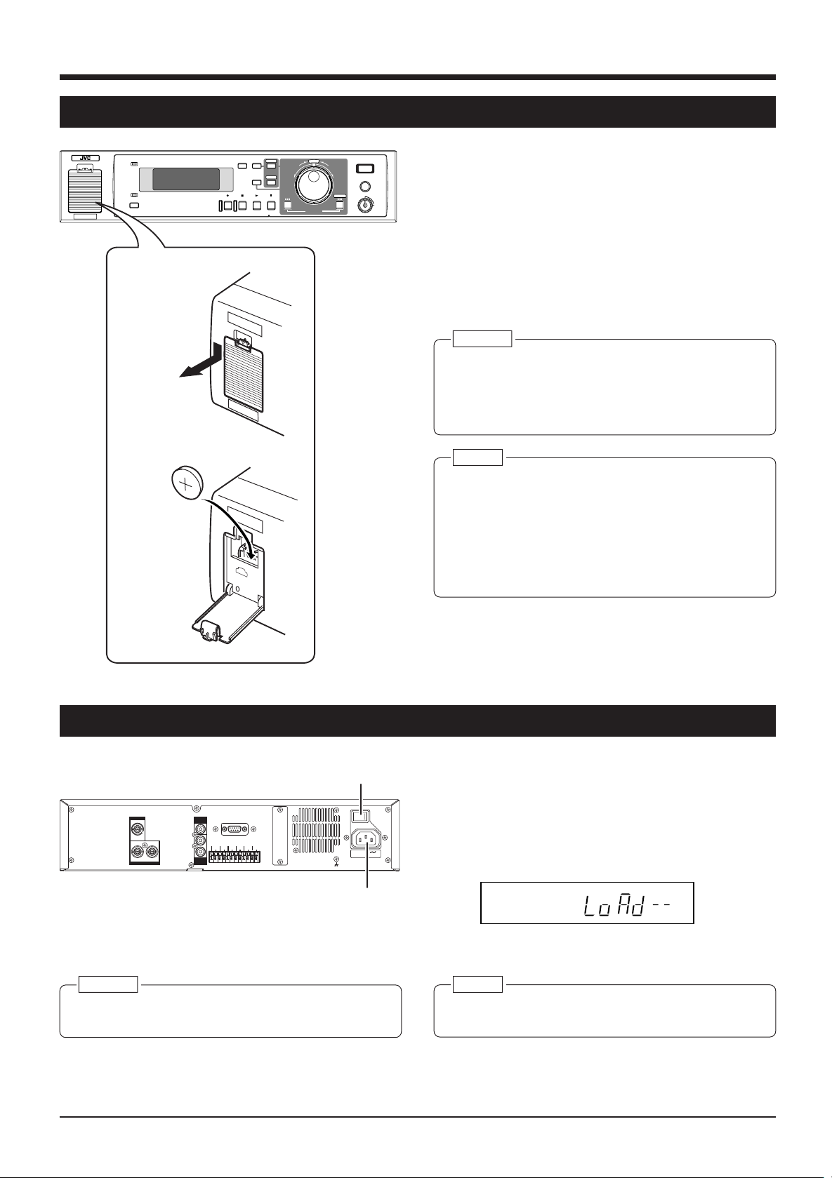
4-1 Installing a battery
2.
3.
POWER
SLEEP
WARNING
TIMER CANCEL
DISPLAY
REC STOP PLAY STILL
MENU
SEARCH
DIGITALVIDEO RECORDER VR-510U
E
C
L
T
E
S
REV FWD
SKIP/ALARM
SEARCH
EXECUTE
REC
CLOCK RESET/ CLEAR
OPE. LOCK
1. Turn the [POWER] switch OFF.
2. Open the battery cover.
ON
While pushing down the pawl in the upper section of the
battery cover, pull it towards you to open the cover.
3. Install a battery.
Install the provided battery (CR2032) with the + side
facing you.
4. Close the battery cover.
Close it until the pawl is locked firmly.
Caution:
● When the power is supplied, do not replace the battery.
Otherwise, a malfunction may occur.
● Replace the battery with a CR2032 type battery. Using
any other type of battery may present a risk of fire or
explosion.
Memo:
● When you replace the battery, be sure to set the date
and time again.
Reference: “4-3 Setting the date and time” on page 13.
● After replacing the battery, be sure to program the
program timer again because the programs are reset.
● When “LOW BATTERY” is displayed, check the battery
again.
4-2 Power supply
[POWER] switch
POWER
ON OFF
CAMERA IN
1
12
MONITOR OUT
AUDIO
RS-232C
IN
1
CAM SW
ALARM
EXT
ALARM
CLOCK
OUT
IN1
REC IN
RESET
RESET IN
SPARE
CLOCK
SPARE SPARE
COM COM
HDD
RESET OUT
FULL OUT
2
AUDIO
OUT
Caution:
● After all other equipment connections are complete,
turn the power of this unit ON.
I
AC IN 120 V
SIGNAL GND
50 Hz / 60 Hz
[AC IN] socket
1. Connect the power cable.
Connect the provided power cable to an AC 120 V outlet.
O
2. Press the [POWER] switch to ON.
The system check starts for this unit and “SYSTEM
LOADING ...” is displayed on the monitor.
“LoAd--” blinks on the display panel.
VN
S
Memo:
● All operation functions are disabled during system
check. Wait until “SYSTEM LOADING ...” goes out.
12
Page 13
4 PREPARATION (contd.)
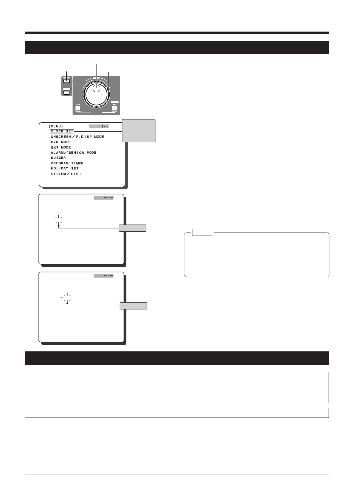
4-3 Setting the date and time
[MENU] button
3.
[
4.
[
5.
Jog dial
MENU
REV FWD
SEARCH
SKIP/ALARM
SEARCH
OGJ
CLOCK S E T
MDY H M
DAYL GHT SAV I NG OFFI
CLOCK S E T
MDY H M
DAYL GHT SAV I NG OFFI
]
1 1 2001
]
1 1 2001
Shuttle dial
E
C
L
T
E
S
JOG
0:00
JOG
0:00
EXECUTE
Characters
selected with
the cursor are
highlighted.
Blinking
Blinking
1. Turn the power ON.
Check the connections and press the [POWER] switch
ON.
2. Display the main menu.
Press the [MENU] button to display the main menu
screen.
Refer to “Jog/shuttle dial operation” on page 16 and set
the jog dial function with the shuttle dial operation.
3. Display the [CLOCK SET] screen.
Set the cursor on [CLOCK SET] with [JOG ]. Turn the
f
shuttle dial to display the [CLOCK SET] screen.
4. Set the month.
Set “month” with [JOG – +].
5. Set the day.
Set the blinking cursor on “D” with [JOG p[] and set
the day with [JOG – +].
6. Set the year, hour and minute.
Repeat the procedure for step 5 for setting.
7. Enter.
When all settings are complete, press the [MENU] button
twice to restore the normal screen.
Note:
● If the date is changed when there is recorded data on
the hard disk, make sure the recording date and time
do not overlap.
Otherwise, playback operation, skip search and direct
search may not function correctly.
4-4 Daylight-saving compensation
Use the <DAYLIGHT SAVING> menu switch on the CLOCK
SET setting screen to turn the Daylight Saving mode ON or
OFF.
When <DAYLIGHT SAVING> is “ON”, the set time is
advanced one hour.
During daylight-saving time Standard time
1. Set the time one hour behind the actual time.
2. After setting the time, set the <DAYLIGHT SAVING>
switch to “ON”.
• The time advances one hour.
3. At the end of the daylight-saving time season, set the
<DAYLIGHT SAVING> switch to “OFF”.
• The standard time is displayed.
• When setting the time, make sure the <DAYLIGHT
SAVING> switch is “OFF”.
When the unit is shipped, this switch is set to “OFF”.
• Clock setting is not possible during timer recording.
1. Set the clock to the actual time.
2. When the daylight-saving season starts, set the <DAYLIGHT SAVING> menu switch to “ON”.
• The display time advances one hour.
13
Page 14
5 ON-SCREEN DISPLAY/MENU SWITCHES
5-1 On-screen display
Date, time, number of alarms and remaining hard disk capacity can be displayed on-screen. Date and time data can be
recorded together with the video signals by setting the <TIME DATE REC> menu switch to “ON”.
AL/SENS DET
MARK
Number of alarms*
Hard disk remaining
capacity
<On-screen display>
Month/day/year/
day of week
113 10
AL
000056 70
A
L
POWER
WARNING
SLEEP
Time (24-hour)
MON
000100
:
:
%
[MENU] button
DISPLAY
MENU
SEARCH
TIMER CANCEL
REC STOP PLAY STILL
REV FWD
Shuttle dial
DIGITAL VIDEO RECORDER VR-510U
E
C
L
T
E
S
SKIP/ALARM
SEARCH
EXECUTE
REC
CLOCK RESET/ CLEAR
OPE. LOCK
ON
Preparation
Jog dial
Connect the monitor’s video signal input connector to the
VR-510U’s [MONITOR OUT] connector.
1. Turn ON this unit and the monitor.
● When a signal is input to the video input connector, onscreen data is superimposed on the picture.
● If no signal is input, on-screen data is superimposed on
a black screen.
To change the position of the on-screen
display
* “SN-***” is displayed in the sensor recording mode.
[On-screen position]
AL
113 10
MON
000100
:
Display items
000056 70
A
L
000056 70
AL
AL
113 10
[
ONSCREEN
1.
ONSCREEN POS I T IOONLUUP
2.
DAY
3.
TIME
4.
ALARM C NT
5.
REC R MEAIN
6.
AL SE SNDETMARK
7.
WARNIGN
[
FRONT DI SPLAY]
1.
REC TALLY
2.
ALARM
:
%
%
MON
000100
:
MODE ]
SENS RO
INDI ACTION
:
JOG
Upper
right
Upper
left
ON
Set with menu switch <ON SCREEN POSITION>.
Reference: “5-3 Menu switch details” on page 19.
To select the contents of the on-screen
display
Set on the [ON SCREEN MODE] screen.
Set the items you want to display to “ON”.
If you do not want to display an item, set it to “OFF”.
* For menu switch setting, refer to “Setting” in “5-2 Menu
switches” on page 18.
To record the on-screen display
Set menu switch <TIME DATE REC>, <DAY> and
NO
NO
NO
NO
NO
NO
NO
1
<TIME> to “ON”.
* If <DAY> and <TIME> are set to “OFF”, the on-screen
display will not be recorded even if <TIME DATE REC> is
set to “ON”.
14
Page 15
5 ON-SCREEN DISPLAY/MENU SWITCHES (contd.)
5-2 Menu switches
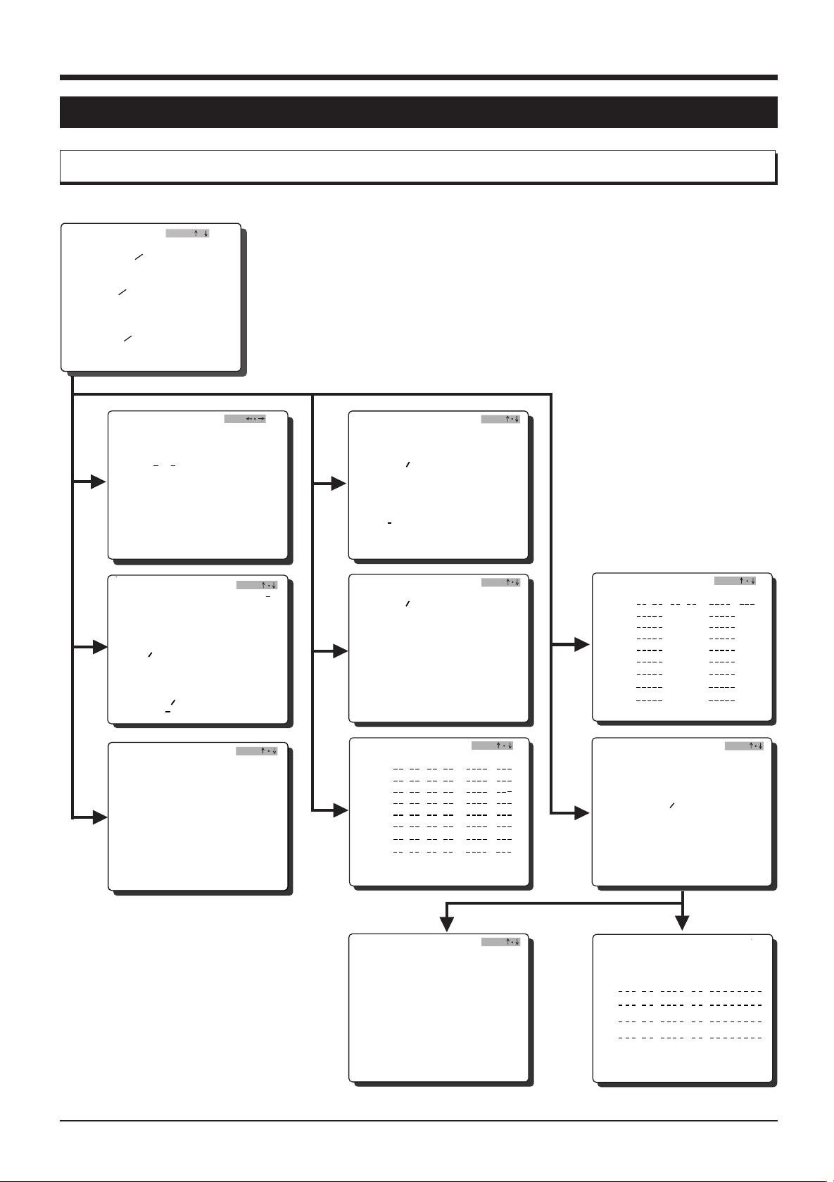
Menu flow
Main menu screen
[ENU]M
CLOCK SET
CNSCR
EEN
DVRMODE
EXTMODE
ALARM
BUZZER
PROGRAM T I
HOLI DAY S E
SYSTEM L I
SENSOR MODE
OGJ ¥
F.DI SP MODE
MER
T
ST
[
CLOCK S E T
MDY H M
DAYL G HT SAVI NG OFFI
[
ONSCREEN
1.
ONSCREEN POS I T IOONLUUP
2.
DAY
3.
TIME
4.
ALARM C NT
5.
REC R MEAIN
6.
AL SE SNDETMARK
7.
WARNIGN
[
FRONT DI SPLAY]
1.
REC TALLY
2.
ALARM
[DVR MODE]
1. REC QUALI TY
2. REC SPEED
REC T IME
3. AUDIOREC
4. POWERON REC
5. SEARCH BUTTO N
SK IPRADU TI O N
6.
7.
REPEAT REC
8.
TIME D TAEREC
9.
O PERAT E LO CK MODE
. EXT ISW TCHER10
]
112001
SENS RO
INDI ACTION
JOG
0:00
MODE ]
JOG
JOG
ON
NORM
30
27H
ON
ON
METI
1HOUR
OFF
O
ALL
O
[
EXT MODE
1. R EC
2. H DD
[
ALARM SENSOR MODE ]
1. R EC
2. R EC
3. PRES
4. PRES
[
BU ZZER
1. H DD
NO
NO
NO
NO
NO
NO
NO
1
N
N
2. A LAR
3. WARN N GI
[
SUN
MON
TUE
WE D
THU
FR I
SAT
DAY
DAI L Y SET
]
MODE OFF
FULL OUT OFF
MODE OFF
DURAT ONI
R
ENSO
RECOFF
R
ENSO
REC DURATI ON
]
END
SENSOR
M
PRO
GR
TUE
: :
: :
: :
: :
: :
: :
: :
:
AM T I MER
WE
]
JOG
MODEST ART END
:
SUN
D
FR I
THU
OGJ
180
10SEC
OGJ
PRG
MON
SAT
SEC
ON
ON
ON
[
ID
AY SET
HO L
: :
1:
3:
5:
7:
9:
11 :
13 :
15 :
]
[
SYSTEM
Y
UTI L I T
[
LIST]
HOUR METER
POWERLOSSLIST
]
JOG
PRG
MODEST ART END
2:
4:
6:
8:
10 :
12 :
14 :
16 :
OGJ
[
BG08]
[
1. A UTO
2. MANU
3. QU I CK ERASE
]Y
UT I LI T
SC ND I SKA
SC ND I SKA
AL
CURRENTFORMAT
OGJ
OFF
OFF
OFF
STD
[
[
PL
PL
PL
PL
HOUR M
HDD R
POWER
TER]E
UN T I ME
OSS LI ST ]L
::
::
::
::
00H0000
15
Page 16

5 ON-SCREEN DISPLAY/MENU SWITCHES (contd.)
5-2 Menu switches (contd.)
Jog/shuttle dial operation
Use the jog/shuttle dial to set the menu or search menu items.
E
C
L
T
E
S
REV FWD
Jog dial
1. Menu or search screen
Turn the shuttle dial.
2. Menu or search screen
JOG
JOG p[
Shuttle dial
f
Shuttle dial operation
Turn the shuttle dial to the right or left so that it passes the
SELECT position.
Main menu or search menu screen
• Turning the shuttle dial displays the selected main menu
or search menu screen for menu switch setting.
Menu switch setting screen
• Each time the shuttle is turned, the jog operation function
is switched.
OGJ
JOG
+
OGJ
Jog dial operation
1. JOG function
f
Turn the jog dial to move the cursor or blinking mark up
and down.
Turn the shuttle dial.
3. Menu or search screen
Turn the shuttle dial.
JOG -
2. JOG p[ function
Turn the jog dial to move the cursor or blinking mark to
the right and left.
3. JOG – + function
Turn the jog dial to change the set value.
+
Memo:
● For setting procedure, refer to the page 17 and on.
16
Page 17

5 ON-SCREEN DISPLAY/MENU SWITCHES (contd.)
5-2 Menu switches (contd.)
Display
<Main menu screen>
[ENU]M
CLOCK SET
CNSCR
EEN
DVRMODE
EXTMODE
ALARM
BUZZER
PROGRAM T I
HOLI DAY S E
SYSTEM L I
F.DI SP MODE
SENSOR MODE
MER
T
ST
Jog dial
POWER
SLEEP
WARNING
[MENU] button
DISPLAY
MENU
SEARCH
TIMER CANCEL
REC STOP PLAY STILL
REV FWD
Shuttle search dial
DIGITAL VIDEO RECORDER VR-510U
E
C
L
T
E
S
SKIP/ALARM
SEARCH
EXECUTE
REC
CLOCK RESET/ CLEAR
OPE. LOCK
ON
[DISPLAY] button
Connect the [MONITOR OUT] connector to the
monitor’s video input connector.
OGJ
The characters
selected with the
cursor are
highlighted.
1. Turn this unit and the monitor ON.
2. Display the main menu screen.
Press the [MENU] button to display the main menu
screen on the monitor.
Switch the jog dial function with the shuttle dial as
described in “Jog/shuttle dial operation” on page 16.
3. Select the item to be set.
Turn the Jog dial (in JOG mode) to move the cursor
f
over the desired item.
4. Display the menu switch setting screen.
Turn the shuttle dial to display the menu switch setting
screen for the selected item.
5. Return to the main menu screen.
To restore the main menu screen, press the [MENU]
button. Press it again to restore the normal screen.
Main menu item details
Clock setting
To display the date and clock setting screen. Before
using this unit for the first time, you must set the date
and time.
Reference: “4-3 Setting the date and time” on page 13.
On-screen display setting
To set items to be displayed on screen.
Front display setting
These menu switches are used to set indicator lighting
preferences.
DVR mode setting
These menu switches are used to set operation preferences including recording picture quality and repeat
recording/playback.
External recording setting
These menu switches are used to specify settings for the
externally activated automatic recording and switching
signal output ON/OFF when the hard disk is full.
Alarm/sensor recording setting
These menu switches are used to set alarm/sensor
recording preferences.
Buzzer setting
These menu switches switch the alarm/sensor buzzer
and the full hard disk warning buzzer ON/OFF.
Program timer setting
To display the program setting screen for timer recording.
Holiday setting
To display the timer recording program setting screen for
a specified date such as a holiday.
System setting
These menu switches are used to set maintenance
preferences such as disk scanning and formatting.
17
Page 18

5 ON-SCREEN DISPLAY/MENU SWITCHES (contd.)
5-2 Menu switches (contd.)
Setting
3.
5.
6.
<Main menu screen>
[ENU]M
CLOCK SET
CNSCR
EEN
DVRMODE
EXTMODE
ALARM
BUZZER
PROGRAM T I
HOLI DAY SE
SYSTEM L I
[DVR MODE]
1. REC QUALITY
2. REC SPEED
REC T IM E
3. AUDIOREC
4. POWERON REC
5. SEARCH BUTTO N
SK IPRADU T I O N
6.
7.
REPEAT REC
8.
TIME D TAEREC
9.
O PERAT E LO CK MODE
. EXT ISW TCHER10
[DVR MODE]
1. REC QUALITY
2. REC SPEED
REC T IM E
3. AUDIOREC
4. POWERON REC
5. SEARCH BUTTO N
6.
SK IPRADU T I O N
7.
REPEAT REC
8.
TIME D TAEREC
9.
O PERAT E LO CK MODE
. EXT ISW TCHER10
1.
2.
3.
OGJ
F.DI SP MODE
SENSOR MODE
MER
T
ST
JOG
NORM
30
27H
ON
ON
METI
1HOUR
OFF
O
N
ALL
O
N
JOG
NORM
30
27H
ON
ON
METI
1HOUR
OFF
O
N
ALL
O
N
VN
S
REC QUALITY REC SPEED
VN
S
Set when this indicator
blinks rapidly.
VN
S
Set when this indicator
blinks rapidly.
The characters
selected with
the cursor are
highlighted.
Select with JOG .
Select with
JOG – +.
Connect the [MONITOR OUT] connector to the
monitor’s video input connector.
1. Turn this unit and the monitor ON.
Data is displayed on-screen.
2. Display the main menu screen.
Press the [MENU] button to display the main menu
screen.
Switch the jog dial function with the shuttle dial as
described in “Jog/shuttle dial operation” on page 16.
3. Select the item to be set.
Turn the Jog dial [JOG ] to move the cursor over the
f
desired item.
4. Display the menu switch setting screen.
Turn the shuttle dial to display the menu switch setting
screen for the selected item.
f
5. Select the menu switch to be set.
Select the menu switch item to be set with [JOG ].
f
6. Change the set value.
Change the set value with [JOG – +].
* To change the other menu switches, press the [MENU]
button to return to the main menu screen.
7. Quit the menu switch setting.
When all settings are complete, press the [MENU] button
twice. The normal screen is restored.
Set <REC QUALITY> and <REC SPEED> on the
display panel.
1. Set the recording set display.
Press the [DISPLAY] button for about 2 seconds (not
available during recording).
The <REC SPEED> setting section blinks slowly.
Switch the jog dial function with the shuttle dial as
described in “Jog/shuttle dial operation” on page 16.
2. Set <REC SPEED>.
When the shuttle dial is turned, the <REC SPEED>
setting section blinks rapidly. Turn the jog dial to set the
required recording speed.
3. Set <REC QUALITY>.
Turn the shuttle dial so that the <REC SPEED> setting
section blinks slowly. Turn the jog dial so that the <REC
QUALITY> setting section blinks slowly. Repeat the
procedure in Step 2 to set the picture quality.
4. End setting.
Press the [DISPLAY] button to restore the normal display.
* If the Record mode is engaged during setting, the
normal display is automatically restored (ALARM/
SENSOR MODE, etc.).
18
Page 19

5 ON-SCREEN DISPLAY/MENU SWITCHES (contd.)
5-3 Menu switch details
The setting in [ ] is the factory setting.
Setting item Menu switch Setting value Description
ON SCREEN ON SCREEN [UP-L] Sets the on-screen display position.
MODE POSITION UP-R
LOW-L
LOW-R
DAY [ON] Sets the on-screen day/month/year display.
OFF ON : Displayed.
OFF: Not displayed.
TIME [ON] Sets on-screen clock display
OFF ON : Displayed.
OFF: Not displayed.
ALARM COUNT [ON] Sets the on-screen alarm/sensor number display.
OFF ON : Displayed.
OFF: Not displayed.
REC REMAIN [ON] Sets the on-screen remaining hard disk capacity display.
OFF ON : Displays the remaining capacity (does not display it
when the repeat recording is set to “ON”).
OFF: Does not display the remaining capacity.
AL/SENS DET [ON] Sets whether or not the “AL” mark is displayed on screen
MARK OFF during alarm/sensor recording.
ON : Displayed.
OFF: Not displayed.
WARNING [ON] Sets whether or not warnings are displayed on screen when
OFF an abnormality occurs.
ON : Displayed.
OFF: Not displayed.
FRONT DISPLAY REC TALLY [ON] Sets whether or not the recording indicator on the front panel
OFF lights during recording.
ON : Indicator lights.
OFF: Indicator does not light.
ALARM/SENSOR [ON1] Sets whether or not the recording indicator blinks when
INDICATION ON2 an alarm/sensor signal is input.
OFF ON1 : Indicator blinks during alarm/sensor recording.
ON2 : Indicator blinks when alarm/sensor recording is com
pleted (this mode can be released with the [CANCEL]
button).
* ON1 and ON2 are effective only when menu switch <REC
TALLY> is set to “ON”.
OFF: The indicator lights during alarm/sensor recording.
DVR MODE REC QUALITY HIGH Sets the recording picture quality.
[NORM] HIGH : High-quality recording.
BASIC NORM : Normal-quality recording.
LOW BASIC : Middle-quality recording.
LOW : Low-quality recording.
Reference: “11-1 Recording time” on page 47.
REC SPEED [30] Sets the number of frames to be recorded. The displayed
15 value shows the number of frames recorded in one second.
10 <REC TIME> shows the available recording time on the hard
5 disk. The amount of recording time available depends on the
3 settings of <REC SPEED> and <REC QUALITY>, as well on
2 the amount of free space remaining on the disk.
1 Reference: “11-1 Recording time” on page 47.
1/2
1/5
1/10
19
Page 20

5 ON-SCREEN DISPLAY/MENU SWITCHES (contd.)
5-3 Menu switch details (contd.)
Setting item Menu switch Setting value Description
DVR MODE AUDIO REC [ON] Sets whether or not audio signals are recorded during
POWER ON REC ON Sets whether or not recording re-starts when the power is
SEARCH BUTTON [TIME] Selects the [SEARCH] button function.
SKIP DURATION 1 MINUTE Selects the duration to skip when time search is performed.
REPEAT REC [OFF] Sets whether or not repeat recording is executed.
TIME DATE REC [ON] Sets whether or not time/date is recorded during recording.
OPERATE LOCK [ALL] Sets the lock operation when the operation lock is set to “ON”.
MODE REC ALL : Locks all buttons on the front panel.
EXT SWITCHER [ON] Sets whether or not to use an external switcher.
EXT MODE REC MODE [OFF] Sets whether or not automatic recording is executed with an
HDD FULL OUT [OFF] Sets whether or not the “HDD FULL” signal is output.
OFF recording.
ON : Records audio signals.
OFF: Does not record audio signals.
*When menu switch <REC SPEED> is set to "1/5" or"1/10",
this item will be automatically set to "OFF".
[OFF] restored after a power failure.
To automatically re-start recording, set this switch to “ON”.
ALARM TIME : Executes time search when the [SEARCH] button is
EVENT pressed.
ALARM: Executes alarm search when the [SEARCH] button is
pressed.
EVENT : Executes event search when the [SEARCH] button is
pressed.
Reference: “7-3 Skip search” on page 33.
5 MINUTE
10 MINUTE
30 MINUTE
[1 HOUR]
4 HOUR
1 DAY
1 WEEK
AL•STOP OFF : Repeat recording is not executed.
AL•LOCK AL·STOP : Repeat recording is not possible if an alarm
ALL recording is executed even once.
AL·LOCK : The alarm recording is protected from overwriting
during repeat recording.
ALL : When no space is available for recording, previous
recording are overwritten, starting with the oldest
recording.
Reference: “Repeat recording during alarm recording” on
page 28.
OFF ON : Records the time/date.
OFF: Does not record the time/date.
*If menu switches <DAY>, <TIME> and <AL/SENS DET
MARK> are set to “OFF”, the on-screen display is not
recorded regardless of this setting.
REC : Locks the [STOP] button on the front panel so hard disk
recording cannot be stopped.
* Set to “ALL” for timer recording.
OFF OFF: External switcher not used (no signal output from the
[CAM SW OUT] terminal).
ON : Uses an external switcher (signals output from the [CAM
SW OUT] terminal).
TRIG external trigger signal.
MANUAL OFF : Does not execute automatic recording.
TRIG : Starts recording with an external signal.
MANUAL : Executes recording while external signals are input.
ON OFF: Does not output an HDD FULL signal.
ON : Outputs a signal when the remaining capacity of the
hard disk is 0%. When <REPEAT REC> is set to “ALL”,
signals are not output.
20
Page 21

5 ON-SCREEN DISPLAY/MENU SWITCHES (contd.)
5-3 Menu switch details (contd.)
Setting item Menu switch Setting value Description
ALARM/ REC MODE [OFF] Sets the alarm or sensor recording.
SENSOR MODE ALARM OFF : Does not execute alarm/sensor recording.
REC DURATION 10 SEC Selects the recording duration when an alarm or sensor signal
PRESENSOR REC [OFF] Sets whether or not pre-sensor recording is executed.
PRESENSOR REC [10 SEC] Selects the recording duration when menu switch
DURATION 30 SEC <PRESENSOR REC> is set to “ON”.
BUZZER HDD END [OFF] Sets whether or not the buzzer sounds when the hard disk is
ALARM/SENSOR [OFF] Sets whether or not the buzzer sounds during alarm/sensor
WARNING [OFF] Sets whether or not the buzzer sounds when a warning occurs.
UTILITY AUTO SCANDISK [OFF] Sets whether or not the disk is scanned when the power is
MANUAL SCAN [OFF] When this switch is set to “ON” and the [SKIP
DISK ON SEARCH·EXECUTE] button is pressed, the disk is scanned.
QUICK ERASE [OFF] Selects whether the hard disk is formatted with standard or
SENSOR ALARM : Executes alarm recording.
SENSOR : Executes sensor recording.
Reference: “6-4 Alarm recording” on page 28 and “6-5 Sensor
recording” on page 29.
15 SEC is input.
30 SEC 10 SEC : Executes alarm/sensor recording for 10 sec.
60 SEC 15 SEC : Executes alarm/sensor recording for 15 sec.
120 SEC 30 SEC : Executes alarm/sensor recording for 30 sec.
[180 SEC] 60 SEC : Executes alarm/sensor recording for 60 sec.
MANUAL 120 SEC : Executes alarm/sensor recording for 120 sec.
180 SEC : Executes alarm/sensor recording for 180 sec.
MANUAL: Executes alarm recording for as long as an alarm
signal is input.
*Recording continues about 5 seconds after the set duration
has passed.
(<AL/SENS DET MARK> is also shown.)
ON To execute pre-sensor recording, set this switch to “ON”.
Reference: “Pre-sensor recording” on page 29.
60 SEC Reference: “Pre-sensor recording” on page 29.
ON full (during recording).
OFF: The HDD end buzzer does not sound.
ON : The buzzer sounds.
ON recording.
OFF: The buzzer does not sound.
ON : The buzzer sounds.
ON OFF: The buzzer does not sound.
ON : The buzzer sounds.
ON turned ON.
OFF: Disk is not scanned.
*The disk is not scanned unless the Record mode is engaged
before the power is turned OFF.
ON : Scans the disk when the power is turned ON.
Reference: “8-1 Hard disk maintenance” on page 36.
Reference: “8-1 Hard disk maintenance” on page 36.
STD extended mode.
EXTN When the disk is formatted, all existing data on the hard disk
will be erased.
OFF : Does not format.
STD : Normally, use this position. Up to 13,000 alarm/
sensor events can be recorded.
EXTN : Set to this position if you want to be able to record
more than 13,000 alarm/sensor events (up to about
100,000 events).
* Extended formatting takes about 5 minutes to complete.
Recording time is shorter than with the standard format.
Reference: “8-1 Hard disk maintenance” on page 37.
21
Page 22

6 RECORDING
6-1 Basic operation
POWER
WARNING
SLEEP
[REC] button
Operation
1. Turn the power ON.
Check the connections and set the [POWER] switch on
the rear panel to ON.
2. Set the menu switches.
Set the menu switches as required. For details, refer to
“Setting” on page 17. For major menu switches, refer to
the description shown on the right.
3. Start recording.
Press the [REC] button to start recording.
4. Stop recording.
Press the [STOP] button to stop recording.
Memo:
● Recording duration can be set with a menu switch.
For more details.
Reference: “11-1 Recording time” on page 47.
[MENU] button
Jog dial
DIGITAL VIDEO RECORDER VR-510U
REV FWD
SKIP/ALARM
SEARCH
DISPLAY
MENU
SEARCH
TIMER CANCEL
REC STOP PLAY STILL
[STILL] button
[STOP] button
Major menu switches
[DVR MODE] menu switches
[REC QUALITY] : Sets the recording picture quality.
[REC SPEED] : Sets the number of fields to be
[AUDIO REC] : Sets whether or not audio signals are
[REPEAT REC] : Sets whether or not repeat recording
[TIME DATE REC] : Sets whether or not time/date is
Shuttle search dial
E
C
L
T
E
S
EXECUTE
REC
CLOCK RESET/ CLEAR
OPE. LOCK
ON
recorded per second.
recorded when menu switch <REC
SPEED> is set to a position other than
1/5 or 1/10.
is executed.
When set to “AL·STOP”, “AL·LOCK”
or “ALL”, the [REPEAT REC]
indication lights on the display panel.
Lights
recorded during recording.
<Normal recording>
● As shown in the figure on the
right, recording is performed
consecutively until the hard disk
is full.
● Each recorded section (Rec Start
To Rec End) is called an event.
● Recording stops when the hard
disk is full. Additional recording is
not possible.
* When the hard disk is full (remain-
ing capacity is 0%), a signal is
output from the [HDD FULL]
terminal.
(When menu switch <HDD FULL
OUT> is set to “ON” and menu
switch <REPEAT REC> is not set
to “OFF”)
22
Recording system
Beginning of the hard disk
Event 1
Event 2
Event 3
Event 4
End of the hard disk
Start of
recording
Stop
Start of
recording
Stop
Start of
recording
Stop
Start of
recording
END
<Repeat recording>
● Allows recording to continue
● Recording continues until the
● In the Repeat Record mode,
● When overwriting starts from
when the hard disk is full by
overwriting the oldest previous
recordings.
[STOP] button is pressed.
the on-screen hard disk
remaining capacity indication is
not displayed.
the beginning of an event, the
entire event will be erased.
Event 2 is
erased.
Beginning of the hard disk
Event 4
Overwriting
Event 2
Event 3
Event 4
End of the hard disk
Stop
Start of
recording
Stop
Start of
recording
Page 23

6 RECORDING (contd.)
6-2 Program timer recording
Two types of program timer recording are available: weekly and daily.
[CANCEL] button
[TIMER] button
POWER
WARNING
SLEEP
REC STOP PLAY STILL
( ) TIMER indication
Weekly timer
[MENU] button
TIMER CANCEL
DISPLAY
MENU
SEARCH
Jog dial
Shuttle search dial
DIGITAL VIDEO RECORDER VR-510U
E
C
L
T
E
S
REV FWD
EXECUTE
SKIP/ALARM
SEARCH
REC
CLOCK RESET/ CLEAR
OPE. LOCK
ON
Select with JOG – +.
4.
GR
PRO
SUN
MON
TUE
WE D
THU
FR I
SAT
DAY
DAI L Y S ET
TUE
AM T I M ER
: :
: :
: :
: :
: :
: :
: :
:
WE
]
JOG
PRG
MODEST ART E ND
:
MON
SUN
D
THU
FR I
SAT
[
Set the start time.
5.
6.
10.
GR
PRO
SAT
MON
TUE
WE D
THU
FR I
SAT
DAY
DAI L Y S ET
TUE
[
GR
PRO
START
SAT
08 0 0 17 0 0
MON
TUE
WE D
THU
FR I
SAT
DAY
DAI L Y S ET
TUE
AM T I M ER
: :
: :
: :
: :
: :
: :
: :
:
WE
AM T I M ER
::
: :
: :
: :
: :
: :
: :
:
WE
D
END
D
:
THU
:
THU
]
]
JOG
MODEST ART E ND
SUN
FR I
JOG
MNODE
SUN
FR I
10
PRG
MON
SAT
PRG
WL Y
MON
SAT
[
Memo:
● When audio is not recorded, the [MODE] indication is
reversed.
N 10 [ N 10
1. Turn the power ON.
Check the connections and set the [POWER] switch on
the rear panel to ON.
2. Set [AUDIO REC] to ON/OFF with the <AUDIO REC>
menu switch under <DVR MODE>.
3. Display the [PROGRAM TIMER] screen.
Display the [PROGRAM TIMER] screen. For details,
refer to “Setting” on page 18.
4. Set the day of the week.
Select the day of the week with [JOG – +].
5. Set the start time (hours).
Move the blinking cursor to the start time “hour” with [JOG
p[]. Set the hours with [JOG – +].
6. Set the start time (minutes).
Move the blinking cursor on the start time “minute” with
[JOG p[]. Set the minutes with [JOG – +].
7. Set the stop time hours and minutes.
Set the stop time hours and minutes as described in
steps 5 and 6.
*If the stop time is earlier than or the same as the start
time, the stop time is automatically set to the next day.
“T” will be displayed in front of the stop time.
8. Set the picture quality.
Move the blinking cursor to [MODE] with [JOG p[].
Then select the picture quality with [JOG – +].
H: High-quality recording
N: Normal-quality recording
B: Medium-quality recording
L: Low-quality recording
9. Set frame recording mode (REC SPEED).
Move the blinking cursor with [JOG p[] and select
<REC SPEED> with [JOG – +].
10.Set the timer frequency.
Move the blinking cursor to [PRG] with [JOG p[].
Then, select the frequency mode with [JOG – +].
ON : Timer recording is executed once at the specified
time.
WLY: Timer recording is executed every week at the
specified time on the specified day of the week.
OFF : Timer recording is not executed regardless of
program settings.
11. End program timer setting.
When all settings are complete, press the [MENU] button
twice. The normal screen is restored.
12. Engage the Timer Recording Standby mode.
Press the [TIMER] button to engage the Timer Recording
Standby mode.
The [TIMER] indication ( ) lights on the display panel.
* To cancel or change the setting, refer to page 26.
23
Page 24

6 RECORDING (contd.)
6-2 Program timer recording (contd.)
8.
9.
10.
[
G
PRO
SUN
MON
TUE
WE D
THU
FR I
SAT
DAY
DAI L Y S ET
TUE
[
G
PRO
SUN
MON
TUE
WE D
THU
FR I
SAT
MON
** **
DAI L Y S ET
TUE
[
G
PRO
ST21AR T
SUN
MON
TUE
WE D
THU
FR I
SAT
MON
** **
DAI L Y S ET
TUE
POWER
SLEEP
WARNING
[CANCEL] button
[TIMER] button
REC STOP PLAY STILL
[MENU] button
TIMER CANCEL
DISPLAY
MENU
SEARCH
Jog dial
Shuttle search dial
DIGITAL VIDEO RECORDER VR-510U
E
C
L
T
E
S
REV FWD
EXECUTE
SKIP/ALARM
SEARCH
( ) TIMER indication
Timer-recording for 24 hours or more
Example: High-quality recording at 1/5 frame per
second programmed from 9:00 p.m. Saturday to 8:00
a.m. Monday
1. Turn the power ON.
Check the connections and set the [POWER] switch on
the rear panel to ON.
2. Set [AUDIO REC] to ON/OFF with the <AUDIO REC>
menu switch under <DVR MODE>.
3. Display the [PROGRAM TIMER] screen.
Display the [PROGRAM TIMER] screen. For details,
refer to “Setting” on page 18.
4. Move the cursor to the 7th line.
Move the cursor to [SAT] on the 7th line with [JOG ].
5. Set the day of the week.
Set the blinking cursor on [SAT] with [JOG – +].
6. Set the start time (hours).
Move the blinking cursor to the start time “hour” with [JOG
p[]. Set “21” with [JOG – +].
7. Set the start time (minutes).
Move the blinking cursor to the start time “minute” with
[JOG p[]. Set “00” with [JOG – +].
8. Set the stop time (hours).
Move the blinking cursor on the “hour” for the stop time
with [JOG p[]. Set “**” with [JOG – +].
As you turn the jog dial, the values change as shown
below.
...... “22” [ “23” [ “**” p “0” p “1” p “2” ...
The stop time indications show “**:**
time indications on the 8th line show “**:**”.
9. Set the stop time.
Move the cursor to the day of the week with [JOG p[]
and move it to the 8th line with [JOG ]. Set the day of
the week (MON) and time (08:00) as described in steps 4
to 6.
10.Set the picture quality.
Move the blinking cursor to [MODE] with [JOG p[].
Select “H” with [JOG – +].
11. Set the number of frames for recording.
Move the blinking cursor with [JOG p[] and select “1/
5” with [JOG – +].
12. Set timer frequency.
Move the blinking cursor to [PRG] with [JOG p[].
Select “WLY” with [JOG – +].
13. End timer programming.
When all settings are complete, press the [MENU] button
twice. The normal screen is restored.
14. Engage the Timer Recording Standby mode.
Press the [TIMER] button to engage the Timer Recording
Standby mode.
The [TIMER] indication ( ) lights on the display panel.
* To cancel or change the setting, refer to page 26.
AM T I M ER
R
: :
: :
: :
: :
: :
: :
:
:
WE
AM T I M ER
R
: :
: :
: :
: :
: :
: :
::
00
:
WE
AM T I M ER
R
: :
: :
: :
: :
: :
: :
::
00
:
WE
]
D
:
**
:
D
THU
]
D
EN
**
** **** ***
:
00
08
D
THU
]
D
EN
**
** **** ***
:
00
8
D
THU
JOG
MODEST21AR T00EN
SUN
FR I
JOG
MODEST21AR T
SUN
FR I
JOG
MO
DE
/
H5
SUN
FR I
Set to
PRG
MON
SAT
Set the stop time
PRG
MON
SAT
PRG
WLY
MON
SAT
**
7th line
8th line
REC
CLOCK RESET/ CLEAR
OPE. LOCK
ON
*** **
f
f
”. The start
24
Page 25

6 RECORDING (contd.)
6-2 Program timer recording (contd.)
4.
10.
11.
[
GR
PRO
DAY
MON
TUE
WE D
THU
FR I
SAT
DAY
DAI L Y S ET
TUE
[
GR
PRO
START
DAY
10 0 0 17 0 0
MON
TUE
WE D
THU
FR I
SAT
DAY
DAI LY S ET
TUE
[
GR
PRO
START
DAY
10 0 0 17 0 0
MON
TUE
WE D
THU
FR I
SAT
DAY
DAI L Y SET
Select [DAY].
D
END
D
END
D
]
:
THU
]
:
THU
]
:
AM T I M ER
: :
: :
: :
: :
: :
: :
: :
:
WE
AM T I M ER
::
: :
: :
: :
: :
: :
: :
:
WE
AM T I M ER
::
: :
: :
: :
: :
: :
: :
:
WE
[TIMER] button
POWER
WARNING
SLEEP
( ) TIMER indication
JOG
PRG
MODEST ART E ND
MON
SUN
SAT
FR I
Move the cursor.
JOG
PRG
MODE
ON
N30
SUN
MON
SAT
FR I
Day of the week for timer
recording to be executed
JOG
PRG
MODE
ON
N30
MON
SAT
[CANCEL] button
[MENU] button
TIMER CANCEL
DISPLAY
REC STOP PLAY STILL
Daily timer
1. Turn the power ON.
Check the connections and set the [POWER] switch on
the rear panel to ON.
2. Set [AUDIO REC] to ON/OFF with the <AUDIO REC>
menu switch under <DVR MODE>.
3. Display the [PROGRAM TIMER] screen.
Display the [PROGRAM TIMER] screen. For details,
refer to “Setting” on page 18.
4. Set the day of the week.
Set the blinking day-of-the-week to “DAILY” with [JOG – +].
5. Set the start time (hours).
Move the blinking cursor to the start time “hour” with [JOG
p[]. Set the required time with [JOG – +].
6. Set the start time (minutes).
Move the blinking cursor to the start time “minute” with
[JOG p[]. Set the required time with [JOG – +].
7. Set the stop time hours and minutes.
Set the stop time hours and minutes as described in
steps 5 and 6.
8. Set the picture quality.
Move the blinking cursor to [MODE] with [JOG p[].
Then select the picture quality with [JOG – +].
H: High-quality recording
N: Normal-quality recording
B: Medium-quality recording
L: Low-quality recording
9. Set the recording frame mode (REC SPEED).
Move the blinking cursor with [JOG p[] and select
<REC SPEED> with [JOG – +].
[PRG] is automatically set to “ON”.
10.Set the timer frequency.
Move the cursor to the day-of-the-week position with
[JOG p[] and move it to [DAILY SET] with [JOG ].
11. Select the day of the week for timer recording to be
executed.
Move the blinking cursor with [JOG p[] and select the
day of the week for timer recording with [JOG – +].
When “– –” is selected, timer recording is not executed.
12. End timer programming.
When all settings are complete, press the [MENU] button
twice. The normal screen is restored.
13. Engage the Timer Recording Standby mode.
Press the [TIMER] button to engage the Timer Recording
Standby mode.
The [TIMER] indication ( ) lights on the display panel.
* To cancel or change the setting, refer to page 26.
MENU
REV FWD
SEARCH
Jog dial
Shuttle search dial
DIGITAL VIDEO RECORDER VR-510U
E
C
L
T
E
S
CLOCK RESET/ CLEAR
EXECUTE
SKIP/ALARM
SEARCH
REC
OPE. LOCK
ON
f
25
Page 26

6 RECORDING (contd.)
6-2 Program timer recording (contd.)
Canceling a timer recording program
1. Display the [PROGRAM TIMER] screen.
Display the [PROGRAM TIMER] screen. For details,
refer to “Setting” on page 18.
2. Select the program to be canceled.
Set the cursor on the program to be canceled with [JOG ].
3. Cancel the program.
Press the [CANCEL] button.
The specified program is canceled.
4. End timer program setting.
Press the [MENU] button twice. The normal screen is
restored.
f
Operation in the Timer Recording
Standby mode
Press the [TIMER] button to turn off the [TIMER] indicator.
You can now operate the unit normally.
Press the [TIMER] button again to turn on the [TIMER]
indicator. The Timer Recording Standby mode is engaged.
When all timer recording programs have been executed,
the [TIMER] indicator goes out.
Estimated recording duration
Changing timer program settings
1. Display the [PROGRAM TIMER] screen.
Display the [PROGRAM TIMER] screen. For details,
refer to “Setting” on page 18.
2. Select the program to be changed.
Set the cursor on the program to be changed with
[JOG ].
3. Select the item to change.
Set the blinking cursor on the item you want to change
with [JOG p[].
4. Change the contents of the program.
Change the setting with [JOG – +].
5. End program editing.
Press the [MENU] button twice to restore the normal
screen.
f
During normal timer recording (menu switch <REPEAT REC> set to “OFF”), recording capacity may be limited depending on
the recording picture quality and recording speed. If there is not enough space available on the hard disk, the programmed
recording may not be performed in its entirety. When the hard disk is full, the programmed timer recording is canceled.
In the Repeat mode, previous recordings are overwritten. Be careful when using this mode.
When setting timer recordings, be sure to check how much recording capacity is required for each program. For details,
refer to the table below.
<Hard disk space required for one-hour recording> (STANDARD Format) (80 GB)
AUDIO REC REC QUALITY 30 FPS 15 FPS 10 FPS 5 FPS 3 FPS 2 FPS 1 FPS 1/2 FPS 1/5 FPS 1/10 FPS
ON HIGH 7.14% 3.57% 2.44% 1.25% 0.78% 0.54% 0.31% 0.19%
NORMAL 3.70% 1.85% 1.25% 0.66% 0.43% 0.31% 0.19% 0.13%
BASIC 2.78% 1.41% 0.96% 0.52% 0.34% 0.25% 0.16% 0.12%
LOW 1.85% 0.96% 0.66% 0.37% 0.25% 0.19% 0.13% 0.10%
OFF HIGH 7.14% 3.57% 2.33% 1.16% 0.70% 0.47% 0.23% 0.12% 0.046% 0.023%
NORMAL 3.57% 1.79% 1.18% 0.59% 0.35% 0.23% 0.12% 0.06% 0.023% 0.012%
BASIC 2.70% 1.33% 0.88% 0.44% 0.26% 0.18% 0.09% 0.04% 0.018% 0.009%
LOW 1.79% 0.88% 0.59% 0.29% 0.18% 0.12% 0.06% 0.03% 0.012% 0.006%
<Hard disk space required for one-hour recording> (EXTENSION Format) (80 GB)
AUDIO REC REC QUALITY 30 FPS 15 FPS 10 FPS 5 FPS 3 FPS 2 FPS 1 FPS 1/2 FPS 1/5 FPS 1/10 FPS
ON HIGH 8.33% 4.17% 2.70% 1.41% 0.87% 0.61% 0.35% 0.22%
NORMAL 4.17% 2.08% 1.41% 0.75% 0.48% 0.35% 0.22% 0.15%
BASIC 3.13% 1.59% 1.08% 0.58% 0.38% 0.28% 0.18% 0.13%
LOW 2.08% 1.08% 0.75% 0.41% 0.28% 0.22% 0.15% 0.12%
OFF HIGH 8.33% 4.00% 2.63% 1.32% 0.79% 0.52% 0.26% 0.13% 0.052% 0.026%
NORMAL 4.00% 2.00% 1.33% 0.66% 0.40% 0.26% 0.13% 0.07% 0.026% 0.013%
BASIC 3.03% 1.49% 0.99% 0.50% 0.30% 0.20% 0.10% 0.05% 0.020% 0.010%
LOW 2.00% 1.00% 0.66% 0.33% 0.20% 0.13% 0.07% 0.03% 0.013% 0.007%
* Actual space used may vary depending on disk conditions and the presence of alarm recordings. This table is meant as a guide only.
For 160 GB, the values in the above table should be halved.
<Example>
• When a 3-hour recording is executed with <REC QUALITY> set to “HIGH”, <REC SPEED> set to “30” and <AUDIO REC> set to “OFF”.
7.14 (%) x 3 (hour) = 21.4 (%)
Before programming the timer recording, confirm that the remaining capacity of the hard disk is 22% or more.
26
Page 27

6 RECORDING (contd.)
6-3 Holiday timer recording
Timer recording can be performed on specified days during the year such as holidays. When holiday timer recording and
programmed timer recording overlap, holiday timer recording has a priority.
POWER
SLEEP
WARNING
[CANCEL] button
[TIMER] button
TIMER CANCEL
REC STOP PLAY STILL
( ) TIMER indication
[MENU] button
MENU
SEARCH
DISPLAY
Jog dial
Shuttle search dial
DIGITAL VIDEO RECORDER VR-510U
E
C
L
T
E
S
REV FWD
EXECUTE
SKIP/ALARM
SEARCH
REC
CLOCK RESET/ CLEAR
OPE. LOCK
ON
4.
5.
10.
[
I
D
HO L
A
: :
1:
3:
5:
7:
9:
11 :
13 :
15 :
[
I
HO L
D
A
: :
1
15 9 15
1:
12
2
3:
5:
7:
9:
11 :
13 :
15 :
[
I
HO L
D
A
ST0AR T
::
00
15 9 15
1
1:
12
2
3:
5:
7:
9:
11 :
13 :
15 :
Set with JOG - +.
]
SET
Y
JOG
PRG
MODEST ART E ND
1. Turn the power ON.
Check the connections and set the [POWER] switch on
the rear panel to ON.
2. Set [AUDIO REC] to ON/OFF with the <AUDIO REC>
menu switch under <DVR MODE>.
2:
4:
6:
8:
10 :
12 :
14 :
16 :
3. Display the [HOLIDAY SET] screen.
Display the [HOLIDAY SET] screen. For details, refer to
“Setting” on page 18.
4. Set the desired day.
The cursor blinks at the setting point. Set the day with
[JOG – +] and [JOG p[].
5. Set the start time (hours).
Move the blinking cursor to the “hour” for START with
Set with JOG - +.
[JOG ]. Set the required time with [JOG – +].
6. Set the start time (minutes).
f
Move the blinking cursor to the “minute” for START with
]
SET
Y
END
10 :
12 :
14 :
16 :
JOG
PRG
MODEST0AR T
2:
23
9
4:
6:
8:
[JOG p[]. Set the required time with [JOG – +].
7. Set the stop time hours and minutes.
Set the hours and minutes for END as described in steps
4 and 5.
8. Set the picture quality.
Move the blinking cursor to [MODE] with [JOG p[].
Select the picture quality with [JOG – +].
H: High-quality recording
N: Normal-quality recording
B: Medium-quality recording
L: Low-quality recording
9. Set the frame mode (REC SPEED).
Move the blinking cursor with [JOG p[] and select
<REC SPEED> with [JOG – +].
]
SET
Y
EN23D
10 :
12 :
14 :
16 :
00
2:
4:
6:
8:
JOG
MODE
N1/
9
23
PRG
5
ON
[PRG] is automatically set to “ON”.
10.End HOLIDAY SET.
When all settings are complete, press the [MENU] button
twice. The normal screen is restored.
11.Engage the Holiday Recording Standby mode.
Press the [TIMER] button to engage the Holiday Recording Standby mode.
The [TIMER] indication ( ) lights on the display panel.
* To cancel or change the setting, refer to page 26.
Memo:
● Holiday recordings take priority over normal timer
recordings. (Only [TIMER] indicator lights on the
display panel.)
● Maximum recording for HOLIDAY SET is 24 hours.
27
Page 28

6 RECORDING (contd.)
6-4 Alarm recording
When an alarm signal is received (via the rear panel [ALARM IN] terminal) during recording, the alarm recording mode set with
the menu switch is automatically engaged.
POWER
WARNING
SLEEP
[CANCEL] button
TIMER CANCEL
DISPLAY
REC STOP PLAY STILL
[MENU] button
MENU
SEARCH
Jog dial
Shuttle search dial
DIGITAL VIDEO RECORDER VR-510U
E
C
L
T
E
S
REV FWD
EXECUTE
SKIP/ALARM
SEARCH
REC
CLOCK RESET/ CLEAR
OPE. LOCK
ON
[ALARM/SENSOR] screen
3.
[
EXT MODE
1. R EC
2. H DD
[
ALARM SENSOR MODE]
1. R EC
2. R EC
3. PRES
4. PRES
]
MODE OFF
FULL OUT OFF
MODE ARM
DURAT ONI
R
ENSO
RECOFF
R
ENSO
REC DURATI ON
OGJ
AL
180
10SEC
SEC
Set to “ALARM”.
Memo:
● Recording continues for about 5 seconds after the set
duration has passed.
● Alarm recording speed <REC SPEED> is fixed at “30”.
<AUDIO REC> is fixed to “ON”.
● <REC QUALITY> setting for alarm recording is the same as the
normal recording setting (used before an alarm is detected).
PROGRAM TIMER REC ALARM REC
<REC QUALITY>BASIC Recording with <REC
Before alarm detection
QUALITY> set to "BASIC"
Alarm detection
[REC] button
1. Connect an alarm sensor.
Connect the alarm sensor to the rear panel [ALARM IN]
terminal.
2. Turn the power ON.
Check the connections and set the [POWER] switch on
the rear panel to ON.
3. Set the menu switches.
Set the required menu switches. For details, refer to
“Setting” on page 18.
[ALARM/SENSOR MODE]
[REC MODE] : Set to “ALARM”.
[REC DURATION] : Select how long you want alarm
recording to continue after an alarm signal is input.
[BUZZER]
[ALARM/SENSOR]: Set to “ON” to sound the buzzer
during alarm recording.
Reference: “5-3 Menu switch details” on page 21.
4. Start recording.
Refer to “Basic operation” on page 22.
When an alarm signal is received, alarm recording starts
(see step 3 above).
* To stop the buzzer during alarm recording, press the
[CANCEL] button.
When set to “AL•LOCK”
Beginning of the hard disk
Alarm 1
Normal
recording 1
Alarm 2
Protected
Normal
recording 2
Alarm 3
Normal
recording 3
End of the hard disk
28
Repeat recording during alarm recording
When set to “ALL”
Normal
recording 1
Normal
recording 2
Normal
recording 3
Overwriting
Repeat
recording
Beginning of the hard disk
Alarm 1
Alarm 2
Alarm 3
Alarm 4
Alarm 5
End of the hard disk
Overwriting
Repeat recording
Repeat recording is canceled if even one alarm
recording is performed when menu switch
<REPEAT REC> is set to “AL·STOP”.
When menu switch <REPEAT REC> is set to
“AL·LOCK”, alarm recorded sections are protected
when repeat recording is executed.
When menu switch <REPEAT REC> is set to
“ALL”, all alarm recordings are overwritten except
Alarm 1.
To erase Alarm 1, erase all alarms with the
[CLEAR] button.
If the <REC DURATION> switch in <ALARM/
SENSOR MODE> is set to “MANUAL” and alarm
recording continues, recording will stop when the
disk is full even if menu switch <REPEAT REC> is
set to “ALL”.
Page 29

6 RECORDING (contd.)
6-5 Sensor recording
When an alarm signal is input to the rear panel [ALARM IN] terminal in the Stop mode, sensor recording starts in the mode set
with the menu switch.
POWER
SLEEP
WARNING
[CANCEL] button
TIMER CANCEL
DISPLAY
REC STOP PLAY STILL
[MENU] button
MENU
SEARCH
Jog dial
Shuttle search dial
DIGITAL VIDEO RECORDER VR-510U
E
C
L
T
E
S
REV FWD
EXECUTE
SKIP/ALARM
SEARCH
REC
CLOCK RESET/ CLEAR
OPE. LOCK
ON
(S) SENSOR ON indication
[ALARM/SENSOR MODE] screen
3.
[
EXT MODE
1. R EC
2. H DD
[
ALARM SENSOR MODE]
1. R EC
2. R EC
3. PRES
4. PRES
]
MODE OFF
FULL OUT OFF
MODE OR
DURAT ONI
R
ENSO
RECOFF
R
ENSO
REC DURATI ON
OGJ
E
1S80
10SEC
N
SSEC
Set to “SENSOR”.
Caution:
● Do not use the Sleep mode in the Sensor Recording
Standby mode. If the Sleep mode is engaged, there
will be a delay between the time an alarm signal is
received and sensor recording starts. No images will
be recorded during this period.
Memo:
● Sensor recording speed <REC SPEED> is fixed at
“30”. <AUDIO REC> is fixed to “ON”.
● <REC QUALITY> for sensor recording is set with
<DVR MODE>.
[REC] button
1. Connect an alarm sensor.
Connect the alarm sensor to the rear panel [ALARM IN]
terminal.
2. Turn the power ON.
Check the connections and set the [POWER] switch on
the rear panel to ON.
3. Set the menu switches.
Set the required menu switches. For details, refer to
“Setting” on page 18.
[ALARM/SENSOR MODE]
[REC MODE] : Set to “SENSOR”. (S) lights on the
display panel for the [SENSOR] indication.
[REC DURATION] : Select how long you want sensor
recording to continue after an alarm signal is
received.
[PRESENSOR REC] : Set to “ON” to execute pre-
sensor recording.
[PRESENSOR REC DURATION] : Set the time for
pre-sensor recording.
[BUZZER]
[ALARM/SENSOR]: Set to “ON” to sound the buzzer
during sensor recording.
Reference: “5-3 Menu switch details” on page 21.
4. Engage the Sensor Recording Standby mode.
Engage the Stop mode. When an alarm signal is
received, sensor recording starts (see step 3 above).
* To stop the buzzer during sensor recording, press the
[CANCEL] button.
Pre-sensor recording
In the Pre-sensor Recording mode, recording starts from
the point before an alarm signal is input during sensor
recording.
<Example>
• When <SENSOR REC> and <PRESENSOR REC> are
set to “ON” and <PRESENSOR REC DURATION> is set
to “30” sec.
Memo:
● Even though <PRESENSOR REC> is set to “OFF”,
pre-sensor recording may be performed for about 1
second.
Time
Sensor Recording
Standby (Stop)
mode
Alarm signal
<30 sec.>
Pre-sensor
recording:
Normally recording
is performed with
camera switching.
Sensor recording
29
Page 30

6 RECORDING (contd.)
6-6 Recording with an external activation signal
Recording can be started and stopped externally when an activation signal is input to the rear panel [EXT REC IN] terminal.
1.
CAMERA IN
1
12
MONITOR OUT
Signal input/output
terminals
EXT REC
COM
IN
External control device
Control signal of this unit (ground signal)
Start of recording
[EXT MODE] screen
2.
[
EXT MODE
1. R EC
2. H DD
[
ALARM SENSOR MODE]
1. R EC
2. R EC
3. PRES
4. PRES
]
MODE RI G
FULL OUT OFF
MODE OFF
DURAT ONI
R
ENSO
RECOFF
R
ENSO
REC DURATI ON
Select the automatic recording operation.
POWER
ON OFF
I
SIGNAL GND
AC IN 120 V
50 Hz / 60 Hz
O
AUDIO
RS-232C
IN
1
CAM SW
ALARM
ALARM
CLOCK
EXT
OUT
IN1
RESET
RESET IN
REC IN
SPARE
HDD
CLOCK
2
SPARE SPARE
COM COM
FULL OUT
AUDIO
OUT
RESET OUT
HV:5V
LV:OV
Stop
OGJ
T
180
SEC
10SEC
Connection
1. Connect an external control device.
Connect the external control device to the rear panel
[EXT REC IN] and [COM] terminals.
Operation
2. Turn the power ON.
Check the connections and set the [POWER] switch on
the rear panel to ON.
3. Set the menu switches.
Set the required menu switches. For details, refer to
“Setting” on page 18.
[DVR MODE]
[REC QUALITY] : Set the recording picture quality.
[REC SPEED] : Set the recording speed.
[AUDIO REC] : Sets whether or not audio signals
are recorded when menu switch
<REC SPEED> is set to a position
other than 1/5 or 1/10.
[EXT MODE]
[REC MODE] : Set the recording mode to use when
an activation signal is input.
• When “TRIG” is selected, recording starts when a
signal is input.
To stop recording, press the [STOP] button.
• When “MANUAL” is selected, recording is performed as long as a signal is input.
Reference: “5-3 Menu switch details” on page 19.
4. Engage the Stop mode.
When an activation signal is input to the [EXT REC IN]
terminal, recording starts automatically.
Memo:
● This function is disabled in the Timer Recording
Standby mode.
6-7 Automatic restart of recording after power failure
If a power failure occurs, recording re-starts automatically as soon as the power supply is restored.
To activate this function, set menu switch <POWER ON REC> to “ON”. When power is restored after a power outage, recording
starts again in the same mode in use when power was lost.
JOG
NORM
30
27H
ON
ON
METI
1HOUR
OFF
O
ALL
O
N
N
Caution:
● Because this device automatically performs a system
check when power is restored after a power failure,
there will be a delay before recording re-starts.
Set to “ON”.
30
[DVR MODE]
1. REC QUALITY
2. REC SPEED
REC T IM E
3. AUDIOREC
4. POWERON REC
5. SEARCH BUTTO N
6.
SK IPRADU T I O N
7.
REPEAT REC
8.
TIME D TAEREC
9.
O PERAT E LO CK MODE
. EXT ISW TCHER10
Page 31

7 PLAYBACK AND SPECIAL-EFFECTS PLAYBACK
7-1 Basic operation
POWER
WARNING
SLEEP
Operation
1. Turn the power ON.
Check the connections and set the [POWER] switch on
the rear panel to ON.
2. Start playback.
Press the [PLAY] button. The [PLAY] indicator on the
display panel lights and playback starts.
3. Stop the playback temporarily.
Press the [STILL] button. The [STILL] indicator on the
display panel lights and the Still mode is engaged.
4. Re-start playback.
Press the [PLAY] button to start playback again.
5. Stop playback.
Press the [STOP] button to stop playback.
DIGITAL VIDEO RECORDER VR-510U
REV FWD
SKIP/ALARM
DISPLAY
MENU
SEARCH
TIMER CANCEL
REC STOP PLAY STILL
[STOP] button [STILL] button
[PLAY] button
Memo:
● When the <REC MODE> switch in <ALARM/SENSOR
MODE> is set to “SENSOR” (“SN-***” is shown on
screen), the following phenomena may occur.
• The playback picture appears to stop for a moment or
sound is interrupted.
● If no signal is input from the selected camera during
recording, the picture may freeze or a black screen
may be displayed.
E
C
L
E
S
SEARCH
T
REC
CLOCK RESET/ CLEAR
OPE. LOCK
EXECUTE
ON
Playback
● Press the [PLAY] button to start playback from the point
where playback was last stopped.
Beginning of the hard disk (full)
Event 1
Event 2
Previous playback
Event 3
Playback starts
from the position
where the playback
was last stopped.
Event 4
End of the hard disk (0%)
Memo:
● The screen may go black or sound may be interrupted
during transitions between events.
Simultaneous Playback mode
● Lets you check a recording while recording is taking place.
● Jog/shuttle playback and skip search are available in
addition to normal playback.
● When the [PLAY] button is pressed, playback starts from
the point where playback was last stopped.
Memo:
● When an alarm signal is received, the playback picture
may appear to stop or sound may be interrupted.
However, this does not affect the recording.
31
Page 32

7 PLAYBACK AND SPECIAL-EFFECTS PLAYBACK (contd.)
7-2 Jog/shuttle playback
Jog playback allows you to view a recording one frame at a time while shuttle playback lets you vary playback speed. These
functions are useful when you want to find a specific scene or examine recorded images in more detail. The shuttle dial is the
outer ring and the jog dial is the inner dial.
Jog dial
Shuttle search dial
Reverse search
POWER
WARNING
SLEEP
Still playback
E
C
L
T
E
S
REV FWD
EXECUTE
SKIP/ALARM
SEARCH
Forward search
TIMER CANCEL
REC STOP PLAY STILL
[STOP] button
[PLAY] button
1. Start playback.
2. Turn the shuttle dial.
3. Stop shuttle playback.
DIGITAL VIDEO RECORDER VR-510U
E
C
L
T
E
S
REV FWD
EXECUTE
SKIP/ALARM
SEARCH
REC
CLOCK RESET/ CLEAR
OPE. LOCK
ON
DISPLAY
MENU
SEARCH
[STILL] button
Shuttle playback operation
Press the [PLAY] button to start playback.
To advance the recorded picture, turn the shuttle dial
clockwise (in the [FWD] direction). Search speed
increases when you turn the dial further.
To reverse the picture, turn the shuttle dial counterclockwise (in the [REV] direction).
Press the [STOP], [STILL] or [PLAY] button to stop shuttle
playback. The operation starts according to the button
pressed.
<Shuttle dial position and search speed>
Rewind Center
×-60 p×-15p×-5p×-3p×-1p×-1/6pStill picture[× 1/6[× 1[× 3[× 5[× 15[× 60
Forward
Jog playback operation
1. Start playback.
Press the [PLAY] button to start playback.
2. Turn the jog dial.
To advance the recorded picture, turn the jog dial
clockwise (in the [FWD] direction). To reverse the picture,
turn the dial counterclockwise (in the [REV] direction).
While the jog dial is turned, frame-by-frame playback is
performed. When the dial is released, a still picture
playback is displayed.
3. Stop jog playback.
Press the [STOP] or [PLAY] button to stop jog playback.
The Stop or Play mode will be engaged.
32
Page 33

7 PLAYBACK AND SPECIAL-EFFECTS PLAYBACK (contd.)
7-3 Skip search
When the search distance is specified in the menu, the skip search is possible. This function lets you skip quickly through a
series of events and check each one briefly for alarm points.
Jog dial
Shuttle search dial
2.
[DVR MODE]
1. REC QUALITY
2. REC SPEED
REC T IM E
3. AUDIOREC
4. POWERON REC
5. SEARCH BUTTO N
6.
SK IPRADU T I O N
7.
REPEAT REC
8.
TIME D TAEREC
O PERAT E LO CK MODE
9.
. EXT ISW TCHER10
POWER
SLEEP
JOG
WARNING
NORM
30
27H
ON
ON
METI
1HOUR
OFF
O
ALL
O
Set to “TIME”.
N
N
DISPLAY
MENU
SEARCH
REV FWD
TIMER CANCEL
REC STOP PLAY STILL
[STOP] button [STILL] button
[PLAY] button
[SKIP SEARCH·EXECUTE] button
1. Turn the power ON.
Check the connections and set the [POWER] switch on
the rear panel to ON.
2. Set the menu switches.
Display the [DVR MODE] screen and set the menu
switches. For details, refer to “Setting” on page 18.
[SEARCH BUTTON]: Set to “TIME”.
[SKIP DURATION]: Set the skip distance (time).
3. Start playback.
Press the [PLAY] button to start playback.
4. Execute time search.
Press the [SKIP SEARCH·EXECUTE] button to perform
time search. The Still mode is engaged.
To check the event, press the [PLAY] button.
DIGITAL VIDEO RECORDER VR-510U
E
C
L
T
E
S
REC
CLOCK RESET/ CLEAR
OPE. LOCK
EXECUTE
SKIP/ALARM
SEARCH
Time search
ON
About the time search
<Example>
• Menu switch <SKIP DURATION> is set to “1H”.
10:00 12:15 15:00
Start of recording
Event 1
[SKIP SEARCH·EXECUTE]
button
10:30 11:30 12:30
Current playback position
12:00 13:00
● If the current position is 10:30 and the [SKIP
SEARCH·EXECUTE] button is pressed, the position jumps
to 11:30.
● If the [SKIP SEARCH·EXECUTE] button is pressed again,
the position jumps to 12:30 for event 2.
● If the [SKIP SEARCH·EXECUTE] button is pressed once
more, the position jumps to the start of event 3 (15:00).
● If the [SKIP SEARCH·EXECUTE] button is pressed and
held, it jumps to the end of recording.
Stop
[SKIP SEARCH·EXECUTE]
button
Start of recording
Event 2
Start of recording
Event 3
Stop
[SKIP SEARCH·EXECUTE]
button
Note:
● If date and time are not set, time search cannot be
executed. Set the date and time beforehand.
Reference: “4-3 Setting the date and time” on page 13.
33
Page 34

7 PLAYBACK AND SPECIAL-EFFECTS PLAYBACK (contd.)
7-3 Skip search (contd.)
Jog dial
Shuttle search dial
POWER
WARNING
SLEEP
Event search
1. Turn the power ON.
Check the connections and set the [POWER] switch on
the rear panel to ON.
2. Set the menu switch.
Display the [DVR MODE] screen and set menu switch
<SEARCH BUTTON> to “EVENT”. For details, refer to
“Setting” on page 18.
3. Start playback.
Press the [PLAY] button to start playback.
4. Execute event search.
Press the [SKIP SEARCH·EXECUTE] button to perform
event search. The Still mode is engaged at the start of
the next event.
To check the event, press the [PLAY] button.
DISPLAY
MENU
SEARCH
REV FWD
TIMER CANCEL
REC STOP PLAY STILL
[STOP] button [STILL] button
[PLAY] button
[SKIP SEARCH·EXECUTE] button
1. Turn the power ON.
Check the connections and set the [POWER] switch on
the rear panel to ON.
2. Set the menu switch.
Display the [DVR MODE] screen and set menu switch
<SEARCH BUTTON> to “ALARM”. For details, refer to
“Setting” on page 18.
3. Start playback.
Press the [PLAY] button to start playback.
4. Execute the alarm search.
Press the [SKIP SEARCH·EXECUTE] button to perform
alarm search. The Still mode is engaged at the start of
the next alarm recording.
To check the event, press the [PLAY] button.
DIGITAL VIDEO RECORDER VR-510U
E
C
L
T
E
S
REC
CLOCK RESET/ CLEAR
OPE. LOCK
EXECUTE
SKIP/ALARM
SEARCH
Alarm search
ON
About event/alarm search
In the Event
Search mode
In the Alarm
Search mode
Event 1
[SKIP SEARCH·EXECUTE] button
[SKIP SEARCH·EXECUTE] button
Current position
Event 2
(alarm recording 1)
[SKIP SEARCH·EXECUTE] button
[SKIP SEARCH·EXECUTE] button
Event 3
[SKIP SEARCH·EXECUTE] button
Pre-
sensor
recording
Event 4
(sensor
recording 1)
[SKIP
SEARCH·EXECUTE]
button
Event 5
(alarm
recording 2)
● Each time the [SKIP SEARCH·EXECUTE] button is pressed in the Event Search mode, the head jumps to the start position of
the next recording regardless of whether it is a normal recording or alarm/sensor recording.
● Each time the [SKIP SEARCH·EXECUTE] button is pressed in the Alarm Search mode, the head jumps to the start position of
the alarm/sensor recording.
● If the [SKIP SEARCH·EXECUTE] button is pressed continuously, the head stops at the end of the recording.
● In the Event Search or Alarm Search mode, the head cannot jump to the beginning of the pre-sensor recording.
Event 6
34
Page 35

7 PLAYBACK AND SPECIAL-EFFECTS PLAYBACK (contd.)
7-4 Alarm or day/time direct search
You can access a recording by specifying the alarm number or date/time.
2.
3.
[
SEARCH
AR S EARCH
AL
EDTEA
IM
T
[
SEARC ]H
ALA RM
[
ALA RM
M
21
LIST
NMDYHMo
00009 215210210
00009 011 10310
00009 8 1 10011
00009 7 4 1090
00009 5 6 10210
00009 5 4 10410
00009 5 1 10011
00009 4 5 1090
00009 3 011080
00009 2 6 1050
ENU ]M
M
SEARCH
DYHM
12: 1
2010
5
2
]
EXECUTE: PRESS
029
028
027:
026:
025:
024:
023:
022:
021:
020
OGJ
2
0
:
0
:
1
0
1
0
1
0
0
0
:
The cursor blinks.
OGJ
BUTTON
Caution:
● Be sure to clear the alarm list in the Stop mode. If you try to
clear the list in any other mode, "ALARM LIST CLEAR**%" is
not shown and you will be unable to check progress of the
deletion procedure.
● While the alarm list is being cleared, all buttons are disabled.
Clearing the alarm list can take up to 30 minutes or more. For
example, if the alarm list includes 10,000 events, it takes
about 5 minutes to clear the list.
Memo:
● In the Alarm/Sensor mode, jog/shuttle dial response may be
slow.
2.
3.
[
SEARCH
AR S EARCH
AL
IM
EDTEA
T
[
TIME AD
DYHM
M
5
2
21
EXECUTE: PRESS
ENU ]M
M
ESEARC ]HT
2010
SEARCH
12: 1
OGJ
The cursor blinks.
OGJ
2
BUTTON
Alarm direct search
1. Turn the power ON.
Check the connections and set the [POWER] switch on
the rear panel to ON.
2. Display the [SEARCH MENU] button.
Press the [SEARCH] button to display the [SEARCH
MENU] screen on the monitor.
Switch the jog dial function with the shuttle dial as
described in “Jog/shuttle dial operation” on page 16.
3. Display the [ALARM SEARCH] screen.
Set the cursor to [ALARM SEARCH] with [JOG ]. Turn
the shuttle dial to display the [ALARM SEARCH] screen.
f
4. Search by “month”, “day”, “year”, “hour” and
“minute”.
Operate the shuttle dial so that the month area for the
search date blinks. Set “month”, “day”, “year”, “hour” and
“minute” with [JOG p[] and [JOG – +].
5. To search by Alarm No.
Select the alarm No. to be searched with [JOG ].
f
6. Start the search.
Press the [SKIP SEARCH·EXECUTE] button to start the
search.
When the search ends, the Still mode is engaged. To
check the alarm recording section, press the [PLAY]
button.
Clearing the alarm list
In the Stop mode, open the <ALARM SEARCH> screen and
press the [CLEAR] button to clear the alarm list. "ALARM
LIST CLEAR**%" is shown on the monitor.
* If recording is executed or <REC MODE> in <ALARM/
SENSOR MODE> is set to “SENSOR”, the list cannot be
cleared. To clear the list, first set <REC MODE> to
“ALARM”, then call the [ALARM SENSOR] screen and
press the [CLEAR] button.
Day/time direct search
1. Turn the power ON.
Check the connections and set the [POWER] switch on
the rear panel to ON.
2. Display the [SEARCH MENU] button.
Press the [SEARCH] button to display the [SEARCH
MENU] screen on the monitor.
Switch the jog dial function with the shuttle dial as
described in “Jog/shuttle dial operation” on page 16.
3. Display the [TIME/DATE SEARCH] screen.
Set the cursor to [TIME/DATE SEARCH] with [JOG ].
Turn the shuttle dial to display the [TIME/DATE SEARCH]
screen.
4. Search by “month”, “day”, “year”, “hour” and
“minute”.
Set “M”, “D”, “Y”, “H” and “M” with [JOG p[] and [JOG – +].
5. Start the search.
Press the [SKIP SEARCH·EXECUTE] button to start the
search.
When the search ends, the Still mode is engaged. To check
the alarm recording section, press the [PLAY] button.
* If no recording matching the specified date can be
found, the head jumps to the position closest to the
specified date and time.
f
35
Page 36

8 HARD DISK CONTROL
8-1 Hard disk maintenance
When power is interrupted (disconnection, power failure, etc.) in the Record mode or Sensor Record Standby mode, the
recording information on the hard disk may be damaged. This may cause problems in recording and playback.
To repair the hard disk, two disk scan functions (<AUTO SCANDISK> and <MANUAL SCAN DISK>) are available.
● <AUTO SCANDISK>
If <AUTO SCANDISK> is set to “ON”, the disk is scanned automatically whenever the power is turned on or restored. To cancel
disk scanning, press the [CLOCK RESET/CLEAR] button.
● <MANUAL SCAN DISK>
Execute <MANUAL SCAN DISK> from the menu. This cannot be canceled once it has been started. Do not turn the power
OFF while this operation is in progress. When <AUTO SCANDISK> is set to “OFF” and the power is kept turned on for longtime recording, be sure to execute <MANUAL SCAN DISK> regularly.
It is recommended to perform <MANUAL SCAN DISK> once a month if recording is executed continuously.
[MENU] button
MENU
CANCEL
SEARCH
DISPLAY
PLAY STILL
[SKIP SEARCH·EXECUTE] button
1.
2.
UTI L I T
HOUR METER
POWERLOSSLIST
1. A UTO
2. MANU
3. QU I C K ERASE
Scanning the disk
Jog dial
Shuttle search dial
DIGITAL VIDEO RECORDER VR-510U
E
C
L
T
E
S
REV FWD
SKIP/ALARM
SEARCH
[
[
[
]
SYSTEM
Y
LIST]
AL
]Y
SC ND I SKA
SC ND I SKA
P
ESS BUTTON
R
UT I L I T
CURRENTFORMAT
EXECUTE :
EXECUTE
REC
CLOCK RESET/ CLEAR
OPE. LOCK
[
OGJ
OGJ
[CLOCK
RESET/CLEAR]
ON
button
BG08]
+
ON
OFF
OFF
STD
Scan the disk when the power is ON.
1. Display the [UTILITY] screen.
Display the [UTILITY] screen in the main menu
[SYSTEM/LIST]. For details, refer to “Setting” on page 18.
2. Set the menu switches.
Set the cursor to [AUTO SCAN DISK] with [JOG ] and
set to “ON” with [JOG – +].
When the setting is complete, press the [MENU] button
twice to restore the normal screen.
When the power is turned ON, the disk is scanned and
the "SYSTEM LOADING
%" message is displayed.
**
Scanning progress is indicated in percentage. When disk
scanning is complete, the % indication goes out.
“LoAd --” blinks on the display panel.
VN
S
Scan the disk manually.
1. Display the [UTILITY] screen.
Display the [UTILITY] screen in the main menu
[SYSTEM/LIST]. For details, refer to “Setting” on page 18.
2. Set the menu switches.
Set the cursor to [MANUAL SCAN DISK] with [JOG ]
and set to “ON” with [JOG – +].
£
“EXECUTE: PRESS
monitor.
Reference: “5-3 Menu switch details” on page 21.
3. Scan the disk.
Press the [SKIP SEARCH·EXECUTE] button to start
scanning the disk.
“SCAN DISK
%” is shown on the monitor.
**
BUTTON” is displayed on the
f
f
36
Caution:
● Disk scanning can take up to 3 hours if the hard disk
contains a lot of data.
Memo:
● Even if <AUTO SCANDISK> is set to "OFF", "SYSTEM
LOADING**%" may be displayed when the power is
turned ON.
Page 37

8 HARD DISK CONTROL (contd.)
8-1 Hard disk maintenance (contd.)
When the hard disk is full, re-format it in the standard or extended mode.
[MENU] button
Jog dial
Shuttle search dial
1.
POWER
WARNING
SLEEP
Erasing & formatting
[ENU]M
CLOCK SET
CNSCR
EEN
DVRMODE
EXTMODE
ALARM
BUZZER
PROGRAM T I
HOLI DAY SE
SYSTEM L I
[
SYSTEM
UTI L I T
[
LIST]
HOUR METER
POWERLOSSLIST
SENSOR MODE
]
Y
OGJ
F.DI SP MODE
MER
T
ST
[
OGJ
BG08]
DIGITAL VIDEO RECORDER VR-510U
L
E
S
REV FWD
SKIP/ALARM
SEARCH
DISPLAY
MENU
SEARCH
TIMER CANCEL
REC STOP PLAY STILL
[SKIP SEARCH·EXECUTE] button
Erasing & formatting
1. Display the [UTILITY] screen.
Display the [UTILITY] screen in the main menu
[SYSTEM/LIST]. For details, refer to “Setting” on page 18.
2. Set the menu switches.
Set the cursor to [QUICK FORMAT] with [JOG ] and set
to “STANDARD” or “EXTENSION” with [JOG – +].
“EXECUTE: PRESS £ BUTTON” is displayed on the
monitor.
STD : Normally, use this position. Up to 13,000 alarm/
sensor events can be recorded.
EXTEN : Set to this position if you want to be able to
record more than 13,000 alarm/sensor events.
* Extended formatting takes about 5 minutes to complete.
Recording time is shorter than with the standard format.
Reference: “5-3 Menu switch details” on page 21.
Caution:
● Start-up time will be longer when the extended format
is used and a large number of events have been
recorded. (Start-up takes about 2 minutes with 20,000
events and about 25 minutes with 100,000 events
max.)
E
C
T
REC
CLOCK RESET/ CLEAR
OPE. LOCK
EXECUTE
ON
f
2.
[
UT I L I T
1. A UTO
2. MANU
3. QU I C K ERASE
CURRENTFORMAT
EXECUTE :
AL
SC ND I SKA
]Y
SC ND I SKA
P
R
OGJ
OFF
STD
STD
ESS BUTTON
ON
3. Erase & format the disk.
Press the [SKIP SEARCH·EXECUTE] button to start
formatting the disk.
“FORMAT
+
%” is shown on the monitor.
**
Memo:
● When the disk is formatted, all existing data on the
hard disk will be erased.
37
Page 38

9 TROUBLESHOOTING
9-1 Error indication
Error indications are displayed on-screen whenever there is an abnormality with signal reception, the hard disk, or the menu
settings (such as timer recording setting errors).
On-screen indication/
[WARNING] indication
“HDD ERROR”
The [WARNING]
indication lights.
“HDD FULL”
The [WARNING]
indication lights.
“LOW BATTERY”
The [WARNING]
indication lights.
“FAN MOTOR ERROR”
The [WARNING]
indication lights.
“INPUT SIG ERROR”
The [WARNING]
indication lights.
Cause
The hard disk is not functioning properly.
There is no space on the hard disk for
recording. Even if the required recording
time is short, the number of allowable
recordable events may have been
exceeded (13,000 for standard format or
about 100,000 for extended format).
The backup battery is not installed or
need to be replaced.
The fan motor is not functioning properly.
No video signal is input.
Possible solution
Consult your nearest JVC dealer.
Format the disk to clear all data and
optimize available disk space. Or, set
<REPEAT REC> to “AL•STOP”,
“AL•LOCK” or “ALL”.
* When the disk is formatted, the re-
corded data is erased.
Replace the battery with a new one.
Consult your nearest JVC dealer.
● Engage the Stop mode and check the
connections.
* When “Camera abnormal” is displayed
and recording continues, recording may
not be performed normally. First,
remove the cause of the abnormality.
Page
reference
–
37
12
–
9
“PLEASE SET TIMER
PROGRAM”
No events are programmed for timer
recording.
Check the timer program.
23
38
Page 39

9 TROUBLESHOOTING (contd.)
9-2 No error indication
Problem
No power is supplied.
Operation buttons such
as [REC] and [PLAY] do
not respond when
pressed.
No picture is shown
during playback.
Timer recording is not
possible.
The menu screen can’t
be displayed.
The date/time is not
shown on screen.
Cause
● The power cord may be disconnected.
● The Operation Lock mode may be
engaged.
● The monitor may not be properly
connected.
● The selected camera may not be
transmitting a signal.
● The clock may not be set.
● The Timer Standby Mode may have
been turned off. Is the [TIMER]
indication lit?
● The timer program may not be set
correctly.
● The Timer Standby Mode may be
engaged. Is the [TIMER] indication lit?
● The Record, Play or Simultaneous Play
mode may be engaged.
● <ON SCREEN MODE> may be set to
“OFF”.
Possible solution
● Connect the provided power cord to a
120 V AC outlet.
● Release the Operation Lock mode.
● Connect the monitor correctly.
● Select the camera for recording.
● Check the clock setting.
● Press the [TIMER] button to engage the
Timer Recording Standby mode.
● Check the timer program settings. The
[TIMER] indication blinks if a program
cannot be executed.
● Press the [TIMER] button to release the
timer program.
● Stop the operation, then press the
[MENU] button.
● Set <ON SCREEN MODE> to “ON”.
Page
reference
9
20
9
13
26
19
The date/time is not
recorded.
The timer indication
blinks.
Recording/playback is
not possible.
No sound in playback.
Skip search or direct
search is not possible.
● The clock may not be set.
● Menu switch <TIME DATE REC> may
be set to “OFF”.
● The timer is not programmed or a set
program cannot be executed.
● There may not be enough space
available on the hard disk.
● Cameras may not be connected in
sync.
● <AUDIO REC> may not be “ON”.
● The clock may not be set correctly.
● Set the clock.
● Set menu switch <TIME DATE REC> to
“ON”.
● Re-set the program timer.
● Re-format the hard disk to clear existing
data.
● Input the signals in sync.
● Set <AUDIO REC> to “ON”.
If <REC SPEED> is set to “1/5” or “1/
10”, audio signals cannot be recorded.
● Set the clock.
13
23 – 25,
37
10
19
13
39
Page 40

10 RS-232C INTERFACE
D0D1D2D3D4D5D6D
7
0(SPACE) Start
1(MARK)
Stop
bit bit
10-1 Specifications
9-pin connector specifications
Pin No. Signal Operation Signal direction
3 TXD Transmission data DVR [ CPU
2 RXD Reception data DVR p CPU
6 DSR Data set ready DVR p CPU
Output level
OFF : –5 V or less
ON : +5 V or more
5 GND Signal ground
4 DTR Data terminal ready DVR [ CPU
Data format
• Mode : Non-synchronous
• Character length : 8 bits
• Data rate : 9600 bps
• Parity check : None
• Stop bit : 1
10-2 Protocols and commands
This section provides programming information needed to control the VR-510U via RS-232C.
6
9
1
5
Basic table
[Upper
[
Lower
0 Data 0 ENTER ALARM
1
2 ERROR Data 2
3
4 Data 4
5
6 ALARM Data 6 CLEAR REV JVC-1
7 Data 7
8 Data 8
9 Data 9
A ACK PLAY REV REC REC
B NAK
C
D FWD REV FWD
E
F STOP STILL
0123 4567 89 ABCDE F
FWD
COMPLETE
NOT
TARGET
IN
Data 1 CLEAR ALARM
ERROR REV
Data 3
Data 5
STATUS STATUS
SENSE SENSE
PLAY
FWD x3REV
FWD x1/6 REV x1/6
STILL STILL STEP
FWD x15 REV x15 DATE SET
x3 FF VTR INQ
TIME SET
FWD
SHUTTLE
SHUTTLE TABLE ON
REW
REV DATE
STEP SENSE
TIME
SENSE
BASIC
TABLE ON
REQUEST
40
Page 41

10 RS-232C INTERFACE (contd)
10-2 Protocols and commands (contd.)
JVC table 1
[Upper
[
Lower
0 Data 0 ENTER TIMER
1
2 ERROR Data 2
3
4 Data 4 RIGHT
5
6 ALARM Data 6 CLEAR SET-
7 Data 7
8 Data 8 DOWN ALLIST
9 Data 9 UP
A ACK PLAY SELECT
B NAK
C REPEAT REW REPEAT
D
E
F STOP STILL PB STOP
0123 4567 89ABCDE F
ONSCREEN
ON ON FWD FWD ON
COMPLETE
ON
NOT
TARGET
IN SET
Data 1 CLEAR TIMER
ERROR OFF OFF REV REV OFF TYPE
Data 3 DOWN POSV+
Data 5 SET+ POSH+ PL
ONSCREEN
PROGRAM
STATUS E
SENSE SENSE
RIGHT +
LEFT - SP
ROM
VERSION SEARCH
ONSCREEN
SEL REV SENSE
CANCEL PB CAM
XECUTE
DISP
HLD SET DVR
AL/SNMODE
DVR REC
REC CAM
DATE SET
TDSKIP ALARM
TDSKIP ALARM
TD
EVSKIP
FWD
EVSKIP REMAIN
RESET
SETTING
SET
FF
MODE SENSE
REC REC
FWD
SET STEP
REV DATE
STEP SENSE
TIME SET
OPE LOCK
OPE LOCK
FWD PL/AL
SHUTTLE CNT SNS
REV VR STS JVC-1
SHUTTLE
DVR SETTING
SNS
AL/SN REC REC
M
ODE SNS
DVR REC
DVR REC
CAM SNS
TIME
SENSE
DISK
UTILITY
FORMAT
SENSE
DEVICE
H.METER
SENSE
SENSE
STATUS
TABLE ON
BASIC
TABLE ON
REQUEST
VTR INQ
41
Page 42

10 RS-232C INTERFACE (contd.)
10-3 Commands
Preparation
Connect the RS-232C connector.
Operation commands
The commands to operate this unit are shown below. When
the signal is received normally, this unit returns ACK (0Ah)
and is ready for the operation corresponding to the command
received.
e.g.: Playback
TXD
RXD
Commands Description
3AH PLAY: Playback
3BH SHUTTLE FWD x 3: 3x playback (Play mode only)
3CH SHUTTLE FWD x 1/6: 1/6x playback (Play mode only)
3DH SHUTTLE FWD STILL: Temporal stop (Play mode only)
3EH SHUTTLE FWD x 15: 15x playback (Play mode only)
3FH STOP: Stop
40H ENTER: Enter
41H CLEAR ERROR: Clears the last numeric
4AH REV PLAY: Reverse playback
4BH SHUTTLE REV x 3: Reverse 3x playback
4CH SHUTTLE REV x 1/6: Reverse 1/6x playback
4DH SHUTTLE STILL: Temporal stop
4EH SHUTTLE REV x 15: Reverse 15x playback
4FH STILL: Temporal stop
56H CLEAR: Releases the current mode and error condition.
5FH PB STOP: Stops the playback.
60H TIMER ON: Sets the Timer mode to ON.
61H TIMER OFF: Sets the Timer mode to OFF.
62H PRG: Displays the timer program screen.
63H DOWN, RIGHT: Shifts the item when the timer
64H program/holiday timer is set or the alarm search is set.
65H SET +/-: Selects the setting after SHIFT operation.
66H
68H DOWN RIGHT PLS/LEFT UP MNS: Corresponds
69H to JOG operation on the alarm search screen.
70H ON SCREEN ON: Displays on-screen display.
71H ON SCREEN OFF: Releases on-screen display.
72H ROM VER: Returns the ROM version in the
73H POS V+: Moves the on-screen display vertically.
75H POS H+: Moves the on-screen display
76H CANCEL: Cancels the setting for program.
77H EXECUTE: Execute alarm search on the alarm search
78H ALARM LIST DISPLAY: Enters the alarm search screen
79H HOLIDAY SET DISPLAY: Displays the holiday set screen.
7AH SELECT: Switches the JOG operation in the alarm search
90H TD SKIP FWD: Jumps by the search distance set in the
command received. Releases the error condition.
Restores the normal screen when the timer program
screen is displayed. (Effective only in the Stop mode)
section managing RS-232C.
horizontally.
Clears the alarm list on the [ALARM SEARCH] screen.
screen.
from the normal screen. Restores the normal screen from
the alarm search screen.
Restores the normal screen from the holiday set screen.
(Only effective in the Stop mode)
screen.
menu X times in the forward direction. For the number of
jump times X, specify 2 digits with 30-39H.
(Effective only in the Play mode)
9%H3%H3%H
TXD
RXD
0AH 0AH 0AH
3A
OA
Commands Description
91H TD SKIP REV: Jumps by the search distance set in the
92H TD SEARCH: Jumps to the position with the specified
93H EVENT SKIP FWD: Jumps by the event (recording start to
94H EVENT SKIP REV: Jumps by the event (recording start to
ABH FF: In Repeat Recording mode, jumps to the sector with
ACH REW: In Repeat Recording mode, jumps to the sector with
ADH FWD STEP: Advances one frame in the Still mode.
AEH REV STEP: Reverses one frame in the Still mode.
BOH ALARM FWD: Advances by a specified number of alarms.
B1H ALARM REV: Reverses by a specified number of alarms.
B5H SHUTTLE FWD/REW: Specify shuttle search speeds as 1
COH OPE LOCK ON: Locks all operation buttons.
C1H OPE LOCK ON: Sets the Operation Lock mode to OFF.
C9H DISK UTILITY: Launches the disk utility by specifying this
CAH REC: Starts recording by specifying this command after
menu X times in the reverse direction. For the number of
jump times X, specify 2 digits with 30-39H.
(Effective only in the Play mode)
date. Specify the “month”, “day”, “year”, “hour” and
“minute” for the date with numeric commands (10 digits).
92H 3%H3%H3%H3%H3% H3%H
TXD
RXD
0AH 0AH 0AH 0AH 0AH 0AH 0AH
end) X times in the forward direction. For the number of
jump times X, specify 2 digits with 30-39H.
(Effective only in the Play mode)
end) X times in the reverse direction. For the number of
jump times X, specify 2 digits with 30-39H.
(Effective only in the Play mode)
the last time stamp and enters the Still mode. Otherwise,
jumps to the last address sector of the LBA recording area
and enters the Still mode.
Performs alarm search, time/date search and event search
in the forward direction in the Play mode (depending on
the menu setting).
the oldest time stamp and enters the Still mode.
Otherwise, jumps to the last address sector of the LBA
recording area and enters the Still mode.
Performs alarm search, time/date search and event search
in the reverse direction in the Play mode (depending on
the menu setting).
Specify the search number as 2 digits with 30-39H.
(Effective only in the Play mode)
BOH 3%H3%H
TXD
RXD
Specify the search number as 2 digits with 30-39H.
(Effective only in the Play mode)
digit with 3-3AH.
30:STILL 33: x1/6 36: x3 39: x60
31:x1/18 34: x1/2 37: x5 3A: x360
32: x1/18 35: x1 38: x15
command after REC/DUB REQUEST (FAH).
FAH C9H
TXD
RXD
1 byte Status details
01H Standard format
02H
03H Scan disk
04H Extension format
REC/DUB REQUEST (FAH).
Month
0AH 0AH 0AH
0AH 0AH 0AH
Day
%%H
Yea r
42
Page 43

10 RS-232C INTERFACE (contd.)
10-3 Commands (contd.)
Setup commands
Sets switches on this unit. When the signal is received
normally, this unit returns ACK (0Ah) and is ready to execute
the command received.
Commands Description
74H ON SCREEN SELECT: Switches the on-screen display
86H DVR PB CAMERA SET: Specifies which camera signal to
details.
74H
%%
TXD
RXD
1 byte
Bit Status details
7
6 AL/SENS DET MARK
5 WARNING
4 REMAIN
3 ALARM
2
1 TIME
0DATE
output to the monitor.
86H
TXD
RXD
1 byte
Bit Status details
7 ~ 3
2 ~ 0
H
0AH 0AH
%%
H
0AH 0AH
2-bit 1-bit 0-bit Playback
1 0 0 Fixed
camera
Commands Description
89H DVR SETTING: Sets the DVR-related status data.
89H
TXD
RXD
1 byte
Bit Status details
7 Time date rec 0: OFF, 1: ON
6 Repeat rec 0: OFF, 1: AL•STOP,
5 ~ 3
2 ~ 1 Search button
0 Power ON rec 0: OFF, 1: ON
2 bytes
Bit Status details
7 Operation Lock mode 0: ALL, 1: REC
6
5 HDD full out 0: OFF, 1: ON
4 ~ 3 Ext mode
2 ~ 1 Alarm/sensor indication
0 Rec tally 0: OFF, 1: ON
3 bytes
Bit Status details
7 External switcher
6 0: OFF, 1: ON
5 ~ 4
3
2 Warning buzzer 0: OFF, 1: ON
1 Alarm/sensor buzzer 0: OFF, 1: ON
0 HDD end buzzer 0: OFF, 1: ON
%%H %%H %%H
0AH 0AH 0AH 0AH
AL•LOCK, ALL
5-bit 4-bit 3-bit
0 0 0 1 minute
0 0 1 5 minutes
0 0 0 10 minutes
0 1 1 30 minutes
1 0 1 1 hour
1 0 0 4 hours
1 0 1 1 day
1 1 1 1 week
00: Time, 01: Alarm, 10: Event
00: OFF, 1: Trig, 10: Manual
00: OFF, 01: ON1, 10: ON2
Skip duration
8AH ALARM/SENSOR MODE SET: Sets alarm/sensor
recording-related data
8AH
TXD
RXD
1 byte
Bit Status details
7
6 ~ 4
3 ~ 2
1 ~ 0
%%H%%
0AH 0AH 0AH 0AH
6-bit 5-bit 4-bit
0 0 0 10 sec.
0 0 1 15 sec.
0 1 0 30 sec.
0 1 1 60 sec.
1 0 0 120 sec.
1 0 1 180 sec.
1 1 0 Manual
1-bit 0-bit REC MODE
0 0 OFF
0 1 ALARM
1 0 SENSOR
H
%%
H
PRESENSOR REC DURATION
43
Page 44

10 RS-232C INTERFACE (contd.)
10-3 Commands
Commands Description
8AH ALARM/SENSOR MODE SET: Sets alarm/sensor
8BH DVR REC MODE: Sets the Record mode.
8CH REPEAT REC MODE SET: Sets the repeat recording mode.
8DH DVR REC CAMERA SET: Sets the camera for recording.
8EH DATE SET: Sets month, day and year.
8FH TIME SET: Sets hour, minutes and seconds.
recording-related data
8AH
TXD
RXD
%%H %%H %%H
0AH 0AH 0AH 0AH
2 bytes
Bit Status details
7
6 ~ 5
6-bit 5-bit
0 0 10 sec.
0 1 30 sec.
1 0 60 sec.
PRESENSOR REC DURATION
4 PRESENSOR REC 0: OFF, 1: ON
3 ~ 0
3 bytes
Bit Status details
7 ~ 0
8BH
%%
TXD
RXD
H
0AH 0AH
1 byte
Bit Status details
7
6 Audio recording 0: OFF, 1: ON
5 ~ 4
3 ~ 0
TXD
RXD
5-bit 4-bit REC QUALITY
0 0 HIGH
0 1 NORM
1 1 BASIC
1 0 LOW
3-bit 2-bit 1-bit 0-bit REC SPEED
0 0 0 0 30
0001 15
0010 10
0011 5
0100 3
0101 2
0110 1
0111 1/2
1000 1/5
1 0 0 1 1/10
8CH
%%
H
0AH 0AH
1 byte
Bit Status details
7 ~ 2
1 ~ 0
TXD
RXD
1-bit 0-bit REPEAT REC
0 0 OFF
01AL•STOP
10AL•LOCK
1 1 ALL
8DH
%%
H
0AH 0AH
1 byte
Bit Status details
7 ~ 1
0 1: Camera recording ON
8EH 3%H3%H3% H3%H3%H3%H
TXD
RXD
0AH 0AH 0AH 0AH 0AH 0AH 0AH
8EH 3%H3%H3%H3%H3%H3%H
TXD
RXD
0AH 0AH 0AH 0AH 0AH 0AH 0AH
Month
Hour Minutes
Day
Year
Seconds
SENSE commands
When the command is sent, this unit returns the information
corresponding to the command received.
Command Description
67H STATUS SENSE: Returns unit status (5 bytes).
D7H ● 1st byte
7 Not defined Always outputs “1” .
6 Not defined Always outputs “0”.
5 Not defined Always outputs “0”.
4 REC INHIBIT Outputs with loop recording set to
3 Not defined Always outputs “0”.
2 Not defined Always outputs “0”.
1 Not defined Always outputs “0”.
0 ERROR When the command which cannot be
● 2nd byte
7 EE MODE Outputs video signals input
6 A1 EE MODE Outputs audio signals input from an
5 VIDEO MUTE Always outputs “0”.
4 AUDIO MUTE Always outputs “0”.
3 WARNING HDD warning occurs.
2 Not defined Always outputs “0”.
1 STREAM START
0 STREAM END Detects the stream end point.
● 3rd byte
7 Not defined Always outputs “0”.
6 TIMER REC ON Timer standby is on.
5 Not defined Always outputs “0”.
4 REPEAT Always outputs “0”.
3 Not defined Always outputs “0”.
2 REPEAT MODE During repeat recording.
1 SEARCH MODE During search
0 Not defined Always outputs “0”.
● 4th byte
7 PLAY MODE During playback
6 Not defined Always outputs “0”.
5 Not defined Always outputs “0”.
4 STOP MODE Stops playback or recording.
3 Not defined Always outputs “1”.
2 Not defined Always outputs “0”.
1 REC MODE During recording
0 Not defined Always outputs “0”.
● 5th byte
7 PAUSE MODE Still pictures are played back.
6 Not defined Always outputs “0”.
5 SHUTTLE FWD Shuttle search is being executed in
4 SHUTTLE REV Shuttle search is being executed in
3 SPEED CODE3 Current running mode (see table below)
2 SPEED CODE2 Current running mode (see table below)
1 SPEED CODE1 Current running mode (see table below)
0 SPEED CODE0 Current running mode (see table below)
SPEED CODE 3210 Running mode
Bit 0000 Still pictures being
OFF when no remaining capacity is
available.
received is received. To release this
mode, input CLEAR ERROR (41H).
from an external source.
external source.
Detects the stream start point.
the forward direction.
the reverse direction.
5-byte speed code details
played back.
0010 x1/18
0011 x1/6
0100 x1/2
0101 x1
0110 x3
0111 x5
1000 x15
1001 x60
1010 x360
44
Page 45

10 RS-232C INTERFACE (contd.)
10-3 Commands (contd.)
Commands Description
B9H DVR SETTING SENSE: Returns settings status.
B9H
TXD
RXD
BAH ALARM/SENSOR MODE SENSE: Sets the alarm/sensor
recording-related settings.
TXD
RXD
%%H%%
1 st byte 2nd byte 3rd byte
H
%%
H
1 byte
Bit Status details
7 Time date rec 0: OFF, 1: ON
6 Repeat rec 0: OFF, 1: AL•STOP,
5 ~ 3
5-bit 4-bit 3-bit
0 0 0 1 minute
0 0 1 5 minutes
0 0 0 10 minutes
0 1 1 30 minutes
1 0 1 1 hour
1 0 0 4 hours
1 0 1 1 day
1 1 1 1 week
AL•LOCK, ALL
Skip duration
2 ~ 1 Search button
00: Time, 01: Alarm, 10: Event
0 Power ON rec 0: OFF, 1: ON
2 bytes
Bit Status details
7 Operation Lock mode 0: ALL, 1: REC
6
5 HDD full out 0: OFF, 1: ON
4 ~ 3 Ext mode
00: OFF, 1: Trig, 10: Manual
2 ~ 1 Alarm/sensor indication
00: OFF, 01: ON1, 10: ON2
0 Rec tally 0: OFF, 1: ON
3 bytes
Bit Status details
7 External switcher
6 0: OFF, 1: ON
5 ~ 4
3
2 Warning buzzer 0: OFF, 1: ON
1 Alarm/sensor buzzer 0: OFF, 1: ON
0 HDD end buzzer 0: OFF, 1: ON
BAH
%%H%%H%%
1st byte 2nd byte 3rd byte
H
1 byte
Bit Status details
7
6 ~ 4
6-bit 5-bit 4-bit
0 0 0 10 sec.
0 0 1 15 sec.
0 1 0 30 sec.
0 1 1 60 sec.
1 0 0 120 sec.
1 0 1 180 sec.
1 1 0 Manual
Alarm/sensor recording duration
3 ~ 2
1 ~ 0
1-bit 0-bit REC MODE
0 0 OFF
0 1 ALARM
1 0 SENSOR
Commands Description
BAH
BBH DVR REC MODE SENSE: Returns the recording mode
BCH REPEAT REC ON MODE SENSE: Returns Repeat
BDH DVR REC CAMERA SENSE: Returns recording camera
2 bytes
Bit Status details
7
6 ~ 5
6-bit 5-bit
0 0 10 sec.
0 1 30 sec.
1 0 60 sec.
PRESENSOR REC DURATION
4 PRESENSOR REC 0: OFF, 1: ON
3 ~ 0
3 bytes
Bit Status details
7 ~ 0
information.
BBH
TXD
RXD
%%
1st byte
H
1 byte
Bit Status details
7
6 Audio recording 0: OFF, 1: ON
5 ~ 4
3 ~ 0
5-bit 4-bit REC QUALITY
0 0 HIGH
0 1 NORM
1 1 BASIC
1 0 LOW
3-bit 2-bit 1-bit 0-bit REC SPEED
0000 30
0001 15
0010 10
0011 5
0100 3
0101 2
0110 1
0111 1/2
1000 1/5
1 0 0 1 1/10
Recording mode settings.
BCH
TXD
RXD
%%
H
1 byte
Bit Status details
7 ~ 2
1 ~ 0
1-bit 0-bit REPEAT REC
0 0 OFF
01AL•STOP
10AL•LOCK
1 1 ALL
status.
BDH
TXD
RXD
%%
H
1st byte
1 byte
Bit Status details
7 ~ 1
0 Always returns “1” .
45
Page 46

10 RS-232C INTERFACE (contd.)
10-3 Commands
Commands Description
BEH DATE SENSE: Returns current settings for month, day,
BFH TIME SENSE: Returns current settings for hour, minutes
D0H HDD FORMAT SENSE: Returns hard disk format
D1H DEVICE TYPE: Returns the connected device type.
D2H HOUR METER SENSE: Returns the hour meter.
D4H REMAIN SENSE: Returns the remaining capacity.
D5H PL/AL COUNT SENSE: Returns the number of PL/AL.
and year.
BEH
TXD
RXD
3
%
H3%H3%H3%H3%H3%H
Month Day Year
and seconds.
BEH
TXD
RXD
3
%
H3%H3%H3%H3%H3%H
information.
D0H
TXD
%%
RXD
H
1st byte
1 byte Status details
00H Not defined
01H Standard format
02H Extension format
D1H
TXD
RXD
TXD
RXD
TXD
RXD
TXD
RXD
TXD
RXD
35H 31H 30H 55H
5 1 0 U
D2H
3
%
H3%H3%H3%H3%H3%H
6 5 4 3 2 1
D4H
3
%
H3%H3%H
100 10 1
D5H
3
%
H3%H3%H3%H3%H3%H
9 8 7 6 5 4
ALARM
3%H3%H3%H
3 2 1
POWER LOSS
Hour Minutes Seconds
Commands Description
D6H VR STATUS SENSE: Returns DVR-related status.
D6H
TXD
RXD
95H PL RESET: Resets the PL memory and the PL number.
F6H JVC TABLE ON: Enables JVC TABLE 1. JVC TABLE 1 is
maintained until F7H command is output.
F7H BASIC TABLE ON: Enables BASIC TABLE.
FAH REC/DUB REQUEST: This command is sent before
sending REC/UTILITY command.
FBH VTR/DVR INQ
Returns ACK to check that the connected device is DVR.
%%H%%H%%
1 st byte 2nd byte 3rd byte
H
1 byte
Bit Status details
7
6 Not defined Always outputs “0”.
5 Not defined Always outputs “0”.
4 Not defined Always outputs “0”.
3
2
1 JVC TABLE 1 Returns “1” when JVC
TABLE 1 is open.
0 LOCAL Always outputs “0”.
2 byte
Bit Status details
7 ScanDisk Returns “1” when the disk
is being scanned.
6
5 Format Returns “1” when the disk
is being formatted.
4 HddFull Returns “1” with HDD FULL.
3 TrackFull Returns “1” with track
full.
2
1 SensorRec Returns “1” during sensor
recording.
0 AlarmRec Returns “1” during alarm
recording.
3 byte
Bit Status details
7 Not defined Returns “0”.
6 Not defined Returns “0”.
5 Not defined Returns “0”.
4 Cam in Returns “1” with camera
input.
3 Not defined Returns “0”.
2 ~ 0 PB CAM/MONI CAM
46
Page 47

11 OTHERS
11-1 Recording time
The table below shows the recording time in each picture quality mode. Actual recording time may differ depending on the hard
disk conditions so you should use these figures as guidelines only.
AUDIO REC ON (80 GB)
Format
Standard HIGH 14 28 41 80 129 185 325 523
Extension HIGH 12 24 37 71 115 164 289 465
* If audio signal recording is set to “ON”, it will be automatically set to “OFF” when 1/5 fps or 1/10 fps is selected. No sound will be recorded in this case.
Rec quality
NORMAL 27 54 80 151 234 323 520 749
BASIC 36 71 104 194 295 399 614 841
LOW 54 104 151 271 398 520 749 960
NORMAL 24 48 71 134 208 287 462 666
BASIC 32 63 93 172 262 354 546 748
LOW 48 93 134 241 354 462 665 853
30 FPS 15 FPS 10 FPS 5 FPS 3 FPS 2 FPS 1 FPS 1/2 FPS 1/5 FPS 1/10 FPS
AUDIO REC OFF (80 GB)
Format
Standard HIGH 14 28 43 86 143 215 430 861 2153 4306
Extension HIGH 12 25 38 76 127 191 382 765 1914 3828
Rec quality
NORMAL 28 56 85 170 284 426 853 1706 4265 8531
BASIC 37 75 113 227 379 568 1137 2275 5687 11375
LOW 56 113 170 340 568 852 1704 3408 8520 17041
NORMAL 25 50 75 151 252 379 758 1516 3792 7584
BASIC 33 67 101 202 337 505 1011 2022 5056 10113
LOW 50 100 151 302 504 757 1514 3029 7574 15149
30 FPS 15 FPS 10 FPS 5 FPS 3 FPS 2 FPS 1 FPS 1/2 FPS 1/5 FPS 1/10 FPS
AUDIO REC ON (160 GB)
Format
Standard HIGH 28 57 85 164 264 378 664 1068
Extension HIGH 27 54 80 156 250 357 628 1010
* If audio signal recording is set to “ON”, it will be automatically set to “OFF” when 1/5 fps or 1/10 fps is selected. No sound will be recorded in this case.
Rec quality
NORMAL 56 111 163 308 478 659 1061 1528
BASIC 75 146 213 396 602 813 1253 1716
LOW 111 213 308 553 812 1061 1527 1957
NORMAL 53 105 154 291 452 623 1004 1445
BASIC 71 138 202 375 569 769 1185 1624
LOW 105 201 291 523 768 1003 1444 1851
30 FPS 15 FPS 10 FPS 5 FPS 3 FPS 2 FPS 1 FPS 1/2 FPS 1/5 FPS 1/10 FPS
[Unit: Hours]
[Unit: Hours]
[Unit: Hours]
AUDIO REC OFF (160 GB)
Format
Standard HIGH 29 58 87 175 292 439 878 1756 4390 8780
Extension HIGH 27 55 83 166 276 415 830 1661 4152 8305
* Up to 13,000 events (standard) or 100,000 events (extension) can be recorded (including alarm/sensor events). If many short-duration alarm/sensor events are
recorded, the actual recording time may be less than that shown above.
Rec quality
NORMAL 57 115 173 347 579 869 1739 3479 8698 17397
BASIC 77 154 231 463 773 1159 2319 4639 11598 23197
LOW 115 231 347 694 1158 1737 3474 6949 17374 34749
NORMAL 54 109 164 329 548 822 1645 3291 8228 16456
BASIC 73 146 219 438 731 1097 2194 4388 10971 21942
LOW 109 219 328 657 1095 1643 3286 6573 16434 32869
30 FPS 15 FPS 10 FPS 5 FPS 3 FPS 2 FPS 1 FPS 1/2 FPS 1/5 FPS 1/10 FPS
[Unit: Hours]
47
Page 48

11 OTHER (contd.)
11-2 Signal input/output terminals
Terminals
[CAM SW OUT] camera
switching signal output
[ALARM IN 1] alarm
signal input
[ALARM RESET] alarm
signal reset input
[CLOCK RESET OUT]
clock reset output
[CLOCK RESET IN]
clock reset input
[EXT REC IN] external
automatic recording
signal input
(When menu switch <REC
SPEED> is set to "30")
Ref.Sig
CAN SW OUT
GND
1st field
Signal level Remarks
Open collector
output
2nd field
5 ms
1st field
2nd field
Ground input
High voltage = 5 V
Min. 400 ms
Min. 400 ms
Low voltage = 0 V
High voltage = 5 V to 12 V
High input
About 47 kohms
Ground output
High voltage = 5 V
Min. 400 ms
Min. 400 ms
Low voltage = 0 V
High voltage = 5 V
Low voltage = 0 V
Ground input
Ground input
High voltage = 5 V
Min. 400 ms
Low voltage = 0 V
[HDD FULL OUT] HDD
full signal output
2.5 s to 3.0 s
High voltage = 5 V
Low voltage = 0 V
Ground output
Output impedance of 1 kohm
or less
48
Page 49

11 OTHER (contd.)
11-3 Specifications
<General>
Picture compression : MPEG 2 (1 frame only)
Recording capacity : 80 GB (can be increased up to
160 GB)
Power supply : AC 120 V, 60 Hz
Power consumption : 34 W
Allowable operation
temperature : 5˚C to 40˚C
Allowable storage
temperature : – 20˚C to 60˚C
Allowable operation
humidity : 30% to 80%
Weight : Approx. 6.0 kg
<Video signal system>
Line input : 1.0 Vp-p, 75 ohms (BNC unbal-
anced)
Line output : 1.0 Vp-p, 75 ohms (BNC unbal-
anced)
Effective number of
pixels : 720 x 480 (high picture quality)
360 x 240 (normal picture quality)
360 x 240 (medium picture quality)
360 x 240 (low picture quality)
<Audio signal system>
Number of tracks : 1 ch
Line input level : – 8 dBs, 50 kohms (unbalanced)
Line output level : – 8 dBs, 1 kohm (unbalanced)
Frequency response : 100 Hz to 10 kHz
Audio compression
system : 32 kHz sampling, 16-bit MPEG
layer 2
<Provided accessories>
•Instruction manual x 1
•Power cord x 1
•Lithium battery (CR2032) x 1 (for operation check)
•Operation lock key x 2
<Option>
SA-K51U (optional HDD kit)
* For details, consult an authorized JVC dealer.
DIGITALVIDEORECORDER VR-510U
E
C
L
T
E
S
REV FWD
SKIP/ALARM
SEARCH
REC
CLOCK RESET/ CLEAR
OPE. LOCK
EXECUTE
Unit: mm (inches)
360 (14-3/16)
ON
88 (3-1/2)
<Dimensions>
POWER
SLEEP
420 (16-9/16)
WARNING
TIMER CANCEL
REC STOP PLAY STILL
MENU
SEARCH
DISPLAY
* Design and specifications subject to change without notice.
49
Page 50

Page 51

Page 52

VR-510U DIGITAL VIDEO RECORDER
VICTOR COMPANY OF JAPAN, LIMITED
is a registered trademark owned by VICTOR COMPANY OF JAPAN, LTD.
is a registered trademark in Japan, the U.S.A., the U.K. and many other countries.
© 2002 VICTOR COMPANY OF JAPAN, LIMITED
R
Printed in Japan
LLT0010-001A
 Loading...