

Page 1
PTZ IP DOME CAMERA
VN-V685U
READ ME FIRST
VN-V686BU
LST0817-001B
Thank you for purchasing this JVC product.
Before operating this unit, please read the instructions carefully to ensure the best possible performance.
䡵 This manual contains the general instructions for using this unit.
Please refer to [INSTRUCTIONS] for description on the detailed usage of this unit.
For the latest information, please refer to the AREADMEB file in the CD-ROM supplied with this product.
● The supplied CD-ROM includes [INSTRUCTIONS] (pdf), [API Guide] (pdf), [VSIP Guide] (pdf) and
[Search tool].
䡵 How to Read this READ ME FIRST
● JVC holds the copyright to this manual. Any part or all of this manual may not be reproduced without prior consent
from the company.
● Windows is a registered trademark of Microsoft Corporation in the U.S.
● Product names of other companies described in this manual are trademarks or registered trademarks of the
respective companies. Symbols such as 姠, 姞 and 姝 are omitted in this manual.
● Design, specifications and other contents described in this manual are subject to change for improvements without
prior notice.
Check the Accessories/Attachments.
● Read Me First
● CD-ROM
● Warranty Card (For USA)
● Service Information Card (For USA)
IMPORTANT SAFEGUARDS
1. Read all of these instructions.
2. Save these instructions for later use.
3. All warnings on the product and in the operating instructions should be adhered to.
4. Unplug this appliance system from the wall outlet before cleaning. Do not use liquid cleaners or
aerosol cleaners. Use a damp cloth for cleaning.
5.
Do not use attachments not recommended by the appliance manufacturer as they may cause hazards.
6. Do not use this appliance near water - for example, near a bathtub, washbowl, kitchen sink, or
laundry tub, in a wet basement, or near a swimming pool, etc.
7.
Do not place this appliance on an unstable cart, stand, or table. The appliance may
fall, causing serious injury to a child or adult, and serious damage to the appliance.
Use only with a cart or stand recommended by the manufacturer, or sold with the
appliance. Wall or shelf mounting should follow the manufacturer’s instructions,
and should use a mounting kit approved by the manufacturer. An appliance and
cart combination should be moved with care.
Quick stops, excessive force, and uneven surfaces may cause the appliance and
cart combination to overturn.
8. Slots and openings in the cabinet and the back or bottom are provided for
ventilation, and to insure reliable operation of the appliance and to protect it from
overheating, these openings must not be blocked or covered. The openings
should never be blocked by placing the appliance on a bed, sofa, rug, or other similar surface.
This appliance should never be placed near or over a radiator or heat register. This appliance should
not be placed in a built-in installation such as a bookcase unless proper ventilation is provided.
9.
This appliance should be operated only from the type of power source indicated on the marking label.
If you are not sure of the type of power supplied to your home, consult your dealer or local power
company. For appliance designed to operate from battery power, refer to the operating instructions.
10.For added protection for this product during a lightning storm, or when it is left unattended and
unused for long periods of time, unplug it from the wall outlet and disconnect the antenna or cable
system. This will prevent damage to the product due to lightning and power-line surges.
11.Do not allow anything to rest on the power cord. Do not locate this appliance where the cord will be
abused by persons walking on it.
12.Follow all warnings and instructions marked on the appliance.
13.Do not overload wall outlets and extension cords as this can result in fire or electric shock.
14.Never push objects of any kind into this appliance through cabinet slots as they may touch
dangerous voltage points or short out parts that could result in a fire or electric shock. Never spill
liquid of any kind on the appliance.
15.Do not attempt to service this appliance yourself as opening or removing covers may expose you to
dangerous voltage or other hazards. Refer all servicing to qualified service personnel.
16.Unplug this appliance from the wall outlet and refer servicing to qualified service personnel under
the following conditions:
a. When the power cord or plug is damaged or frayed.
b. If liquid has been spilled into the appliance.
c. If the appliance has been exposed to rain or water.
d. If the appliance does not operate normally by following the operating instructions. Adjust only those controls
that are covered by the operating instructions as improper adjustment of other controls may result in damage
and will often require extensive work by a qualified technician to restore the appliance to normal operation.
e. If the appliance has been dropped or the cabinet has been damaged.
f. When the appliance exhibits a distinct change in performance - this indicates a need for service.
17.When replacement parts are required, be sure the service technician has used replacement parts
specified by the manufacturer that have the same characteristics as the original part. Unauthorized
substitutions may result in fire, electric shock, or other hazards.
18.Upon completion of any service or repairs to this appliance, ask the service technician to perform
routine safety checks to determine that the appliance is in safe operating condition.
Information for Users on Disposal of Old Equipment
[European Union]
This symbol indicates that the electrical and electronic equipment should not be
disposed as general household waste at its end-of-life. Instead, the product
should be handed over to the applicable collection point for the recycling of
electrical and electronic equipment for proper treatment, recovery and recycling
in accordance with your national legislation.
By disposing of this product correctly, you will help to conserve natural resources
and will help prevent potential negative effects on the environment and human
health which could otherwise be caused by inappropriate waste handling of this
product. For more information about collection point and recycling of this product,
please contact your local municipal office, your household waste disposal service
Attention:
This symbol is
only valid in
the European
Union.
or the shop where you purchased the product.
Penalties may be applicable for incorrect disposal of this waste, in accordance
with national legislation.
(Business users)
If you wish to dispose of this product, please visit our web page
www.jvc-europe.com to obtain information about the take-back of the product.
[Other Countries outside the European Union]
If you wish to dispose of this product, please do so in accordance with
applicable national legislation or other rules in your country for the treatment of
old electrical and electronic equipment.
● Ceiling Mount
● Dome Cover
● Te mp l a t e
● Wire Clamp
PORTABLE CART WARNING
(symbol provided by RETAC)
S3125A
FOR USA AND CANADA
CAUTION
RISK OF ELECTRIC SHOCK
DO NOT OPEN
CAUTION:TO REDUCE THE RISK OF ELECTRIC
SHOCK. DO NOT REMOVE COVER (OR
BACK). NO USER-SERVICEABLE PARTS
INSIDE.REFER SERVICING TO
QUALIFIED SERVICE PERSONNEL.
The lightning flash wish arrowhead symbol,
within an equilateral triangle is intended to alert
the user to the presence of uninsulated
"dangerous voltage" within the product's
enclosure that age" within the product's
enclosure that may be of sufficient magnitude to
constitute a risk of electric shock to persons.
The exclamation point within an equilateral triangle
is intended to alert the user to the presence of
important operating and maintenance (servicing)
instructions in the literature accompanying the
appliance.
Information for USA
This device complies with part 15 of the FCC Rules. Changes or modifications not approved by JVC could void the
user's authority to operate the equipment.
This equipment has been tested and found to comply with the limits for a Class A digital device, pursuant to Par t 15 of
the FCC Rules. These limits are designed to provide reasonable protection against harmful interference when the
equipment is operated in a commercial environment. This equipment generates, uses, and can radiate radio
frequency energy and, if not installed and used in accordance with the instr uction manual, may cause harmful
interference to radio communications. Operation of this equipment in a residential area is likely to cause harmful
interference in which case the user will be required to correct the interference at his own expense.
This device complies with Part 15 of the FCC Rules.
Operation is subject to the following two conditions: (1)This device may not cause harmful interference, and (2) this
device must accept any interference received, including interference that may cause undesired operation.
Due to design modifications, data given in this instruction book are subject to possible change without prior notice.
WARNING:
TO REDUCE THE RISK OF FIRE OR ELECTRIC SHOCK, DO NOT EXPOSE THIS
APPLIANCE TO RAIN OR MOISTURE.
AVERITISSEMENT:
POUR EVITERLES RISQUES D’INCENDIE OU D’ELECTROCUTION, NE PAS
EXPOSER L’APPAREILA L’HUMIDITE OU A LA PLUIE.
INFORMATION (FOR CANADA)
RENSEIGNEMENT
This Class A digital apparatus complies with Canadian ICES-003.
Cet appareil num rique de la Class A est
(POUR CANADA)
WARNING (FOR EUROPE):
This is a Class A product. In a domestic environment this product may cause radio interference in which
case the user may be required to take adequate measures.
FOR USA-California Only
This product contains a CR Coin Cell Lithium Battery which contains Perchlorate Material - special
handling may apply.
See
www.dtsc.ca.gov/hazardouswaste/perchlorate
● This installation should be made by a qualified service person and should conform to all local codes.
● This installation shall be in accordance with the National Electrical Code, ANSI/NFPA 70.
The unit is to be powered by an AC 24 V power supply or using the PoE.
The AC 24 V power supply should conform to the following: Class 2 only (For USA), Isolated power
supply only (For Europe and other).
● Any Mention in this manual of Alarm inputs/outputs have not been evaluated by UL to be used for Burglar
Alarm Functionality.
䡵 The latest version
Please visit V.NETWORKS web site to check the latest firmware at
http://www.jvc-victor.co.jp/english/products-e.html
(The latest firmware can be found on V.NETWORKS B download page)
Operating Environment
Recommended Computer Specifications
OS : Windows XP (Professional or Home Edition) (SP2)
CPU : Pentium4 2 GHz or higher
Memory capacity : 1 GB and above
Free hard disk space : 512 MB or more
Display and video card : 1024 x 768 pixels or higher, True Color (24 or 32 bits) VRAM 8 MB or more
Web browser : Internet Explorer
LAN Environment
● 10BASE-T/100BASE-TX network interconnected using devices such as an IEEE802.3-compliant
switching hub.
● IEEE802.3af-compliant switching hub when PoE is used
● IGMPv2-compliant network when multicast is in use.
Memo:
● To use MPEG4 images on the built-in viewer, install the open source codec “ffdshow”. You can download
“ffdshow” from the Internet.
: Windows Vista Business (SP1)
(256 MB and above recommended)
XP : Version 6.0
Vista : Version 7.0
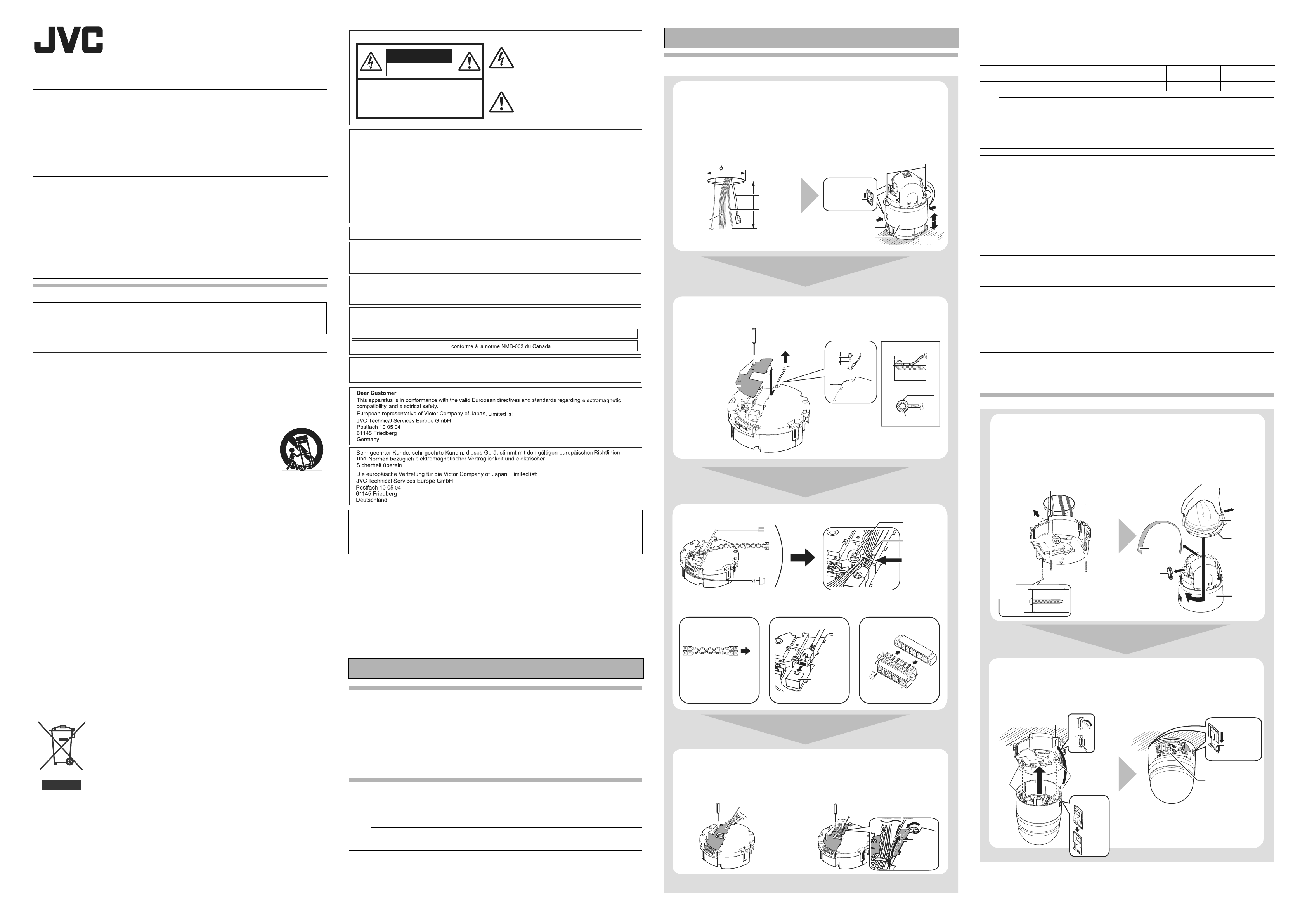
Mounting the Camera
Preparation
Be sure to put on protective glasses to protect your eyes from falling objects when mounting the camera.
1 Make holes on the ceiling (use the provided template) and pull out the
cables from the holes.
2 Remove the ceiling clamping bracket from the camera unit
A
Check to make sure that the two camera lock knobs (left and right) are unlocked. (If they are
locked, unlock by sliding them in the direction indicated by the arrow.)
B
Press the two camera lock knobs from both the left and right sides in the direction indicated by the
arrows. (Perform this task on a table. If the camera fixing lock knob is too stiff, push the knob hard
while pressing the edge of the camera unit (A in the diagram) against the table you are using.)
C
Lift the camera unit upwards to detach.
1
Fall
Prevention
Wire
Alarm signal
cable
80
LAN Cable
Power cable
2
Camera fixing
lock knob
(x2)
Ceiling mount section
Camera
A
B
3 Remove the terminal cover
4
Mount the fall prevention wire that connects the ceiling clamping bracket
to the ceiling
䡵
Fall Prevention Wire
6 mm and below
R6 mm and below
Terminal cover
6 mm
3
4
5 Connect the cables and tie them using wire clamp (provided).
LAN Cable
Power cable
Alarm signal cable
A C
Connecting the alarm signal terminal
D
C
4 mm
B
A
䡵 Connecting to an AC
24 V power supply
To Pow e r Su p p ly
or
䡵 Using PoE
A B LAN Cable Connection
A B LAN Cable ConnectionA A Power Connection
[10BASE-T/
100BASE-TX] LAN
cable connection
terminal
6 Mount the terminal cover
䡵
Pulling out the cables from the side
Terminal cover
䡵 Pulling out the cables from the top
Fall Prevention Wire
(To go under the terminal cover)
A
Ta bl e e tc
R4 to 5.5 mm
Wire clamp fixing
hole
Wire clamp
(provided)
Tie here
Alarm signal
terminal
A
Te rm i n a l
cover
B
C
A Power Connection
Power can be supplied to this camera either by connecting to an AC 24 V power supply or using PoE.
䡵 Power cord in the case for connecting to AC 24 V (Reference value)
Maximum connection
distance
Conductor Diameter (mm) R1.0 and above R1.6 and above R2.0 and above R2.6 and above
Note:
● If the power is supplied from both power cable and LAN cable, the priority is given to the power from the
power cable.
● After DHCP timeout, all IP addresses of the camera
multiple cameras within the same LAN environment are turned on at the same time, the IP address of the
cameras overlap, thus preventing proper access. As such, make sure to turn on the power of the cameras one
by one.
● The rated power of this product is AC 24 V, 50 Hz/60 Hz. Make sure to use it with the correct voltage.
● Supplying a power beyond the rated value may result in failures, smoke or fire. When the camera
breaks down, turn off the power and contact our service center immediately.
● When a power beyond the rated value is supplied, the internal components may be damaged even if
no abnormality is found on the appearance and operation of the camera. Please contact your nearest
JVC dealer immediately for servicing (charged separately).
50 m 150 m 230 m 390 m
are set to 192.168.0.2 by default. When the power of
Warning
B LAN Cable Connection
Connect the camera to a hub or computer using a LAN cable.
● When connecting to a hub : Make use of a straight cable.
● When connecting to a computer : Make use of a cross cable.
Cable to use
● Shield (STP) cable
● Length of 100 m or shorter
● Make use of a Category 5 (or higher) cable
C Connecting the alarm signal terminal
Connect the alarm signal cable to external devices, such as a sensor or buzzer.
A Loosen screws on both sides of the terminal block with a flathead screwdriver and remove the terminal
block.
Memo:
● Inserting the tip of the screwdriver into the slit of the terminal block will remove the terminal block easily.
B Peel off about 4 mm of the alarm signal cable covering and insert into the terminal.
C Turn the screws at the side and secure the alarm signal cable.
D
When the alarm signal cable is secured, return the terminal block that was removed in A to its original position.
Installation
1 Secure the ceiling clamping bracket to the ceiling.
2 Remove the tape and lens cap on the lens section of the camera.
3 Mount the dome cover on the main unit and remove the protective
sheet.
ACheck that the dome cover and lens are free from dirt
B
Turn the dome cover in a clockwise direction to mount
C
Remove the protective sheet
Front of the camera
1
DFRONT mark
Ta pe
3
C
Dome cover
protective sheet
Dome Cover
2
Lens cap
M4x3
(Wooden
screws: R4.1)
25 mm and
above
5 mm and below
Camera
B
4 Mount the fall prevention wire (connects the ceiling clamping bracket
to the camera)
5 Mount the camera and check the camera lock knob.
6 Lock it and remove the sheet.
● Read through details stated on the safety precautions sheet again.
Fall prevention wire fixing bracket
5
D mark
(blue)
4
D mark (red)
Fall Prevention Wire
Check the knob
During
mounting
After
mounting
6
Camera fixing
lock knob (x2)
Sheet
K
Continued
Page 2

IP Address Settings
A
B
C
D
E
A
B
©
IP address setting procedure
Follow the procedure below to configure the IP address of the camera.
Step1 Set the IP address of the computer for configuring the camera settings
Set the IP address of the computer for configuring the camera settings.
K
Step2 Internet Explorer Settings
Configure the Internet Explorer settings in order to establish connection between the computer and the
camera.
K
Step3 Connecting the camera to the computer
Connect the computer to the camera.
K
Step4 IP address setting for the camera
Set the [IP Setting] item on the [Basic Settings1] screen to ADHCP EnableB or ADHCP DisableB.
Step1 Set the IP address of the computer for configuring the camera settings
Camera at factory default is set to ADHCP DisableB (DHCP client function is Off), it will activate under the
following IP address after startup. Set the computer to an IP address that enables communication with the
following. (For example, set the IP address to 192.168.0.100 and subnet mask to 255.255.255.0.)
IP address : 192.168.0.2
Subnet mask : 255.255.255.0
Default gateway : None
䡵 IP address setting at the computer
Set the computer to an IP address that enables communication with the camera.
This item is described basically for Windows XP.
1 Click [Start]
● Select in the sequence of [Control Panel]-[Network Connection]-[Local Area].
Windows Vista:
● Select in the sequence of [Settings]-[Control Panel]-[Network and Sharing Center]-[Manage
network connections].
2 The computer on which Internet Explorer is launched automatically selects the
connected network
●
Right-click and select [Properties].
● Check to ensure that the [Client for Microsoft Networks] and [Internet Protocol(TCP/IP)] check boxes
are selected.
Windows Vista:
● Check to ensure that the [Microsoft Network Client] and [Internet Protocol Version 4(TCP/IPv4)]
check boxes are selected.
3 Select [Internet Protocol(TCP/IP)] and click [Properties]
Windows Vista:
● Select [Internet Protocol Version 4(TCP/IPv4)] and click [Properties]
4 Set the IP address
A
Select [Use the following IP address].
B
Specify the [IP address]. (For example, use 192.168.0.100 when the camera is in its default settings and there is
no DHCP server.)
Memo:
● Make sure that you take note of the original IP address before altering.
● Ensure that a duplicate IP address is not specified within the same network environment.
C
Set [Subnet mask] to a value that is appropriate for the setting operation. Consult the network administrator if you
have any queries. (Use 255.255.255.0 when the camera is in its default settings and there is no DHCP server.)
D
When a [Default gateway] is present, make use of the corresponding IP address (e.g., 192.168.0.254).
E
Click [OK].
3
If the active script of the Internet Explorer is disabled, follow the steps below to enable it
● Select [Trusted sites] under [Tool]-[Internet Options]-[Security]. Upon doing so, the [Sites...] button
directly below becomes active. Click this button and deselect the check in the displayed window, and
add the following web site to the zone.
http://192.168.0.2
● Next, select [Trusted sites] under [Tool]-[Internet Options]-[Security], and press the [Custom Level]
button. Select [Enable] under [Scripting]-[Active script] of the [Security Settings] window that has
been opened.
Select [Enable]
4 If ActiveX controls and plug-ins of the Internet Explorer is disabled, follow the steps
below to enable it
● Click [Trusted sites] under [Tool]-[Internet Options]-[Security]. Select the [Custom Level] button and
open the [Security Settings] window. Set all items under [ActiveX controls and plug-ins] in the opened
window to [Enable]. Enable also [Allow Script-initiated window without size or position constraints]
under [Miscellaneous].
5 Disable pop-up block
Connection of the camera cannot be established when pop-up block in the Internet Explorer is set to
AEnableB. Follow the steps below to set the pop-up block to ADisableB.
● Selecting [Tool]-[Pop-up Blocker]-[Turn Off Pop-up Blocker] permits all sites.
● To allow only specific sites such as this unit, select [Tool]-[Pop-up Blocker]-[Turn Off Pop-up Blocker],
followed by selecting [Tool]-[Pop-up Blocker]-[Pop-up Blocker Settings] that becomes active to open the
[Pop-up Blocker Settings] window.
In the opened window, add the address of the camera as a permitted web site address.
6 When plug-in tools such as the Yahoo or Google toolbar are included in the Internet
Explorer, disable the pop-up block function of these plug-in tools as well
Step3 Connecting the camera to the computer
1 Launch the Internet Explorer
A
Enter the following IP address into the address field. (Example: http://192.168.0.2)
B
Click [Go].
AB
3 Built-in Viewer and the operator password entry screen appear.
A
Enter the Operator Password. (default password is AjvcB)
B
Click [OK].
Step4 IP address setting for the camera
1 Click [Details] of the Built-in Viewer
Click
2 The [Basic Settings1] screen appears
A
Specify the [IP Setting].
䡵 When selecting ADHCP DisableB:
Select DHCP Disable from [IP Setting] item of the camera, and specify a value in the [IP address],
[Subnet Mask] and [Default Gateway] fields.
䡵 When selecting ADHCP EnableB:
The default setting is ADHCP DisableB (DHCP client function is off).
To assign an IP address from the DHCP server, connect the camera to a LAN where the DHCP
server exists.
B
Specify the [Time Zone].
C
Click [OK].
C
A
K
Setting Using Internet Explorer
Configure the picture quality and alarm settings using the Internet Explorer.
T For details, please refer to [INSTRUCTIONS] (pdf) in the supplied CD-ROM.
K
Operating the Built-in viewer
With the built-in viewer, monitoring of JPEG images or MPEG4 images, PTZ operation and registration of
preset positions can be performed.
T For details, please refer to [INSTRUCTIONS] (pdf) in the supplied CD-ROM.
Specifications
Supply voltage : AC 24 V 50 Hz/60 Hz or PoE (DC-48 V)
Current consumption : AC 24 V 1.2 A, PoE 12.95 W
Mass : 1.9 kg
Dimension [Unit: mm (inch)] : R160 (6-19/64) ⳯201 (7-59/64)
T Specifications and appearance of this unit are subject to change for further improvement without prior
notice.
5 Click [OK] on the [Local Area Connection Properties] screen
Step2 Internet Explorer Settings
1 Launch the Internet Explorer on the computer
2 When proxy settings are enabled in the Internet Explorer, follow the steps below to
disable the proxy of the Internet Explorer
● Select in the order of [Tool]-[Internet Options]-[Connections]-
check for [Use a proxy server for your LAN] under [Proxy Server] of the [Local Area Network (LAN) Settings]
window.
[LAN Setting], followed by deselecting the
Memo:
● If the proxy server settings for access to the Internet via the Internet Explorer is enabled, you may not be
able to specify the IP address directly. In this case, change the proxy settings of the Internet Explorer.
● [Basic Settings1] screen can be opened without going through Built-in Viewer by entering the URL
address of the [Basic Settings1] screen in the address field of Internet Explorer.
● VN-V685U
http://192.168.0.2/cgi-in/v685display.cgi?v685basicmenu1.html
● VN-V686BU
http://192.168.0.2/cgi-in/v686display.cgi?v686basicmenu1.html
● After the [Security Settings] screen appears, press the [OK] button to proceed.
䡵 If the IP address is unknown
IP address settings cannot be changed by accessing via a computer when the IP address of the camera
unknown.
You can use the following method to identify the IP address.
●
Search using the ASearch toolB inside the ATOOL_EB folder of the supplied CD-ROM.
T
For details on ASearch toolB, please refer to the AREADMEB file in the CD-ROM supplied with this product.
is
2 Enter the user name and password (login as administrator)
A
Enter the user name. This is set to AadminB by default.
B
Enter the password. This is set to AjvcB by default.
C
Click [OK].
B
Note:
● Set the DHCP server such that the same IP address is always assigned to the MAC address of camera
by the DHCP server. Connection may fail if the above setting is not performed.
3 A confirmation screen appears
● Click [OK].
● Camera restarts using the new IP address. It takes about one minute for the camera to reboot.
Memo:
● Access from this computer may fail when the IP address of camera is changed. To enable access to this
unit from the same computer, alter the IP address at the computer accordingly.
When the display or configuration of the opened screen appears strange, check the computer
settings using the following procedures.
A Click [Start]-[Control Panel]-[Display] and open the [Display Properties] window
B Click the [Settings] tab in the [Display Properties] window and click the [Advanced] button
C Check that [DPI setting] in the [General] tab has become [Normal size(96DPI)]
D Otherwise, change the setting to [Normal size(96DPI)] and reboot Windows
K
Deselect the check
Memo:
● After the [Security Settings] screen appears, press the [Yes] button to proceed.
A
B
C
2009 Victor Company of Japan, Limited
LST0817-001B
 Loading...