

Page 1

4ch Network Encoder
VN-E4
INSTRUCTIONS
This manual describes the detailed usage of VN-E4.
For basic usage of VN-E4, refer to the ASTART-UP GUIDEB.
Refer Readme file the CD-ROM for updated information.
LST0285-001A
Page 2

These are general IMPORTANT SAFEGUARDS and certain items may not apply to all appliances.
S3125A
IMPORTANT SAFEGUARDS
1. Read all of these instructions.
2. Save these instructions for later use.
3. All warnings on the product and in the operating instructions should be adhered to.
4. Unplug this appliance system from the wall outlet before cleaning. Do not use liquid cleaners or aerosol cleaners.
Use a damp cloth for cleaning.
5. Do not use attachments not recommended by the appliance manufacturer as they may cause hazards.
6. Do not use this appliance near water - for example, near a bathtub, washbowl, kitchen sink, or
laundry tub, in a wet basement, or near a swimming pool, etc.
7. Do not place this appliance on an unstable cart, stand, or table. The appliance may fall, causing
serious injury to a child or adult, and serious damage to the appliance.
Use only with a cart or stand recommended by the manufacturer, or sold with the appliance.
Wall or shelf mounting should follow the manufacturer’s instructions, and should use a mounting kit
approved by the manufacturer.
An appliance and cart combination should be moved with care. Quick stops, excessive force, and
uneven surfaces may cause the appliance and cart combination to overturn.
8. Slots and openings in the cabinet and the back or bottom are provided for ventilation, and to insure
reliable operation of the appliance and to protect it from overheating, these openings must not be blocked or covered. The
openings should never be blocked by placing the appliance on a bed, sofa, rug, or other similar surface. This appliance
should never be placed near or over a radiator or heat register. This appliance should not be placed in a built-in installation
such as a bookcase unless proper ventilation is provided.
9. This appliance should be operated only from the type of power source indicated on the marking label. If you are not sure of
the type of power supplied to your home, consult your dealer or local power company. For appliance designed to operate from
battery power, refer to the operating instructions.
10. For added protection for this product during a lightning storm, or when it is left unattended and unused for long periods of
time, unplug it from the wall outlet and disconnect the antenna or cable system. This will prevent damage to the product due
to lightning and power-line surges.
11. Do not allow anything to rest on the power cord. Do not locate this appliance where the cord will be abused by persons
walking on it.
12. Follow all warnings and instructions marked on the appliance.
13. Do not overload wall outlets and extension cords as this can result in fire or electric shock.
14. Never push objects of any kind into this appliance through cabinet slots as they may touch dangerous voltage points or short
out parts that could result in a fire or electric shock. Never spill liquid of any kind on the appliance.
15. Do not attempt to service this appliance yourself as opening or removing covers may expose you to dangerous voltage or
other hazards. Refer all servicing to qualified service personnel.
16. Unplug this appliance from the wall outlet and refer servicing to qualified service personnel under the following conditions:
a. When the power cord or plug is damaged or frayed.
b. If liquid has been spilled into the appliance.
c. If the appliance has been exposed to rain or water.
d. If the appliance does not operate normally by following the operating instructions. Adjust only those controls that are
covered by the operating instructions as improper adjustment of other controls may result in damage and will often require
extensive work by a qualified technician to restore the appliance to normal operation.
e. If the appliance has been dropped or the cabinet has been damaged.
f. When the appliance exhibits a distinct change in performance - this indicates a need for service.
17. When replacement parts are required, be sure the service technician has used replacement parts specified by the
manufacturer that have the same characteristics as the original part. Unauthorized substitutions may result in fire, electric
shock, or other hazards.
18. Upon completion of any service or repairs to this appliance, ask the service technician to perform routine safety checks to
determine that the appliance is in safe operating condition.
2
Page 3
SAFETY PRECAUTIONS (For USA)
The lightning flash wish arrowhead symbol, within
an equilateral triangle is intended to alert the user to
the presence of uninsulated “dangerous voltage”
within the product’s enclosure that may be of
sufficient magnitude to constitute a risk of electric
shock to persons.
The exclamation point within an equilateral triangle is
intended to alert the user to the presence of important
operating and maintenance (servicing) instructions in
the literature accompanying the appliance.
NOTE:
The rating plate (serial number plate) is on the bottom.
SAFETY PRECAUTIONS (For Europe)
NOTE:
This equipment has been tested and found to comply with the limits
for a Class A digital device, pursuant to Part 15 of the FCC Rules.
These limits are designed to provide reasonable protection
against harmful interference when the equipment is operated in a
commercial environment.
This equipment generates, uses, and can radiate radio frequency
energy and, if not installed and used in accordance with the instruction
manual, may cause harmful interference to radio communications.
Operation of this equipment in a residential area is likely to
cause harmful interference in which case the user will be
required to correct the interference at his own expense.
CAUTION
Changes or modifications not approved by JVC could void user's
authority to operate the equipment.
WARNING:
TO REDUCE THE RISK OF FIRE OR ELECTRIC SHOCK, DO
NOT EXPOSE THIS APPLIANCE TO RAIN OR MOISTURE.
CAUTION:
This unit should be used with attached AC Adaptor.
To prevent electric shocks and fire hazards, do NOT use any
other power source.
IMPORTANT:
Connection to the mains supply in the United Kingdom.
DO NOT cut off the mains plug from this equipment.
If the plug fitted is not suitable for the power points in your home or
the cable is too short to reach a power point, then obtain a proper
safety approved extension lead/adaptor or consult your dealer.
In the unlikely event of the plug fuse failing be sure to replace
the fuse only with an identical approved type, as originally
fitted, and to replace the fuse cover. If the fuse fails again
consult your nearest JVC dealer.
If nonetheless the mains plug is cut off remove the fuse and dispose
of the plug immediately, to avoid a possible shock hazard by
inadvertent connection to the mains supply.
If this product is not supplied fitted with a mains plug then follow the
instructions given below:
DO NOT make any connection to the Larger Terminal coded E or
Green.
The wires in the mains lead are coloured in accordance with the
following code:
Blue to N (Neutral) or Black
Brown to L (Live) or Red
If these colours do not correspond with the terminal identifications
of your plug, connect as follows:
Blue wire to terminal coded N (Neutral) or coloured Black.
Brown wire to terminal coded L (Live) or coloured Red.
If in doubt — consult a competent electrician.
WARNING:
TO REDUCE THE RISK OF FIRE OR ELECTRIC SHOCK,
DO NOT EXPOSE THIS APPLIANCE TO RAIN OR
MOISTURE.
CAUTION
To prevent electric shock, do not open the cabinet. No user
serviceable parts inside. Refer servicing to qualified service
personnel.
WARNING
This is a Class A product. In a domestic environment this
product may cause radio interference in which case the user
may be required to take adequate measure.
Caution for AC Mains Lead
FOR YOUR SAFETY PLEASE READ THE FOLLOWING TEXT CAREFULLY.
This product is equipped with 2 types of AC cable. One is for continental Europe, etc. and the other one is only for U.K.
Appropriate mains cable must be used in each local area, since the other type of mains cable is not suitable.
FOR CONTINENTAL EUROPE, ETC. FOR U.K. ONLY
Not to be used in the U.K. If the plug supplied is not suitable for yoursocket outlet, please
use an appropriate one.
ATTENTION:
This symbol is
only valid in the
European Union.
Information for Users on Disposal of Old Equipment
[European Union]
This symbol indicates that the electrical and electronic equipment should not be disposed as general household waste at its
end-of-life. Instead, the product should be handed over to the applicable collection point for the recycling of electrical and
electronic equipment for proper treatment, recovery and recycling in accordance with your national legislation.
By disposing of this product correctly, you will help to conserve natural resources and will help prevent potential negative
effects on the environment and human health which could otherwise be caused by inappropriate waste handling of this
product. For more information about collection point and recycling of this product, please contact your local municipal office,
your household waste disposal service or the shop where you purchased the product.
Penalties may be applicable for incorrect disposal of this waste, in accordance with national legislation.
(Business users)
If you wish to dispose of this product, please visit our web page www.jvc-europe.com
of the product.
[Other Countries outside the European Union]
If you wish to dispose of this product, please do so in accordance with applicable national legislation or other rules in your
country for the treatment of old electrical and electronic equipment.
to obtain information about the take-back
3
Page 4

Introduction
䡵How to view this manual
䡵 Symbols used
Note Items concerning the operations of this product are described.
Memo References concerning the usage, restrictions, etc. of this product are described.
A Reference pages and reference items are indicated.
䡵 About the contents of this manual
● All rights reserved by JVC. Unauthorized duplication or reprinting of this manual, in whole or in part, is strictly prohibited.
● Windows is a registered trademark of Microsoft Corporation in the U.S.
● All other product names used in this manual are trademarks or registered trademarks of their respective companies. Please
note that marks such as 姠, 姞, 姝, etc. have been omitted in this manual.
● Illustrated designs, specifications and other contents of this manual are subject to change without prior notice.
䡵Copyrights in this manual
● With the exception of the user being the copyright holder or when permission has been granted concerning duplication, etc. by
the copyright holder, permission is required in principle for the duplication, modification, transmission, etc. of copyrighted
video/audio.
Unauthorized duplication, modification, transmission, etc. of copyrighted material may constitute a copyright infringement and
the user may be liable to compensate for any damages. When using copyrighted video/audio, be sure to check thoroughly the
license agreement, etc. of the copyrighted material. When there are rights or right holders of the duplicating subject, usage or
processing permission may be required. Be sure check thoroughly the licensing conditions, etc.
● Open source software is partially used for this unit. For information concerning the software, click AOpen Source SoftwareB in
the A5-14 Miscellaneous PageB of page 41.
4
Page 5

Introduction (continued)
䡵Features
Distribution of 4-channel images to the network
VN-E4 compresses 4-channel video input images in the
JPEG format. For VN-E4U, each channel may be
distributed at a maximum rate of 30 fps. The maximum rate
for 4 channels is 120 fps in total. For VN-E4E, each channel
may be distributed at a maximum rate of 25 fps. The
maximum rate for 4 channels is 100 fps in total. Either VGA
or QVGA may be selected as the frame size. It is also
possible to simultaneously distribute a video input in both
types of frame sizes.
Clients may be able to acquire these JPEG via TCP. Up to
10 JPEG or audio streams may be sent via TCP. For
example, when acquiring 4 JPEG and 1 audio stream via
TCP using the built-in viewer, a maximum of 2 built-in
viewers may be connected to each VN-E4.
Multicast transmission of JPEG is also possible with
VN-E4. Multicast transmission of up to 10 streams is
possible.
Audio distribution to the network
VN-E4 compresses 1-channel audio input in the µ-law
format. Clients may acquire µ-law via TCP. Multicast
transmission of µ-law is also possible with VN-E4.
VN-E4 comes with a built-in echo canceller. Use this during
bi-directional audio transmission.
Reception and output of audio signals from the
network
VN-E4 enables output of µ-law received from the network
as audio signals.
Built-in Viewer
VN-E4 comes with a built-in ActiveX viewer. Monitoring of
VN-E4 images and audio using the PC is possible by
installing this built-in viewer on the PC.
Motion detect and alarm input
VN-E4 is equipped with motion detect function that can
detect motion in each video input. It also comes with a
4-channel alarm input. It is possible to invoke actions such
as notification to clients, alarm output, sending of mails and
JPEG file transfer during detection of motion or alarm input.
Actions may also be invoked using a combination of 2
conditions.
Controlling external devices connected to the
serial port
VN-E4 comes with 2 serial ports. It is possible to control
external devices connected to the serial ports from the
clients.
Controlling external devices
The built-in viewer of VN-E4 may be used to control JVC
cameras and cameras that support the Pelco-D protocol.
Restrictions on Clients
VN-E4 can permit or deny access from clients based on
registered IP addresses.
5
Page 6

Introduction (continued)
䡵CONTENT
Introduction
Preparation
How to view this manual ..................................................................................... 4
Copyrights in this manual .................................................................................... 4
Features .............................................................................................................. 5
CONTENT ........................................................................................................... 6
Cautionary Notes ................................................................................................ 7
Name and Function of Parts ............................................................................... 8
1. System Setup Examples ..............................................................................10
1-1 Remote monitoring using the built-in viewer ............................................... 10
1-2 Systems that combine other manufacturer’s devices ................................. 12
2. Requirements for network using VN-E4 .......................................................14
2-1 Network Bandwidth ..................................................................................... 14
2-2 Network Delay ............................................................................................. 15
2-3 Network Jitter ..............................................................................................15
2-4 Packet Loss ................................................................................................15
2-5 Use of Multicast .......................................................................................... 15
3. IP Address Setting ........................................................................................16
3-1 VN-E4 with Factory Default Settings ........................................................... 16
3-2 VN-E4 for which IP address is known ......................................................... 16
3-3 When IP address of VN-E4 is unknown ......................................................16
4. Connection / Installation ...............................................................................17
4-1 AC Adaptor .................................................................................................17
4-2 Network .......................................................................................................17
4-3 [COM1,2] Serial Port Terminals .................................................................. 18
4-4 Alarm Input .................................................................................................. 18
4-5 Alarm Output ............................................................................................... 18
4-6 AV Devices ................................................................................................. 19
4-7 Attaching Rack Mount Brackets .................................................................. 19
4-8 Connection with PC .................................................................................... 19
Settings
Operation
Others
5. Setting Using Internet Explorer ....................................................................20
5-1 JPEG View Page (Top Page) ..................................................................... 21
5-2 Input Page ................................................................................................... 23
5-3 Encoding Page ............................................................................................ 24
5-4 Alarm Page ................................................................................................. 25
5-5 Alarm Environment Page ............................................................................ 26
5-6 Serial Page .................................................................................................29
5-7 Basic Page ..................................................................................................30
5-8 Details Page ................................................................................................ 31
5-9 Streaming Page .......................................................................................... 32
5-10 Access Restrictions Page ......................................................................... 33
5-11 Time Page ................................................................................................. 34
5-12 Password Page ......................................................................................... 35
5-13 Maintenance Page .................................................................................... 36
5-14 Miscellaneous Page .................................................................................. 41
5-15 Operation Page ......................................................................................... 42
5-16 Settings Page ............................................................................................ 43
6. Using the VN-E4 Built-in Viewer ...................................................................46
6-1 Screen Configuration of Built-in Viewer ...................................................... 46
6-2 Built-in Viewer Settings ............................................................................... 48
6-3 GUI for External Device Control .................................................................. 50
7. Troubleshooting ............................................................................................53
8. Specifications ...............................................................................................54
6
Page 7

Introduction (continued)
䡵Cautionary Notes
About GPL
Part of the software that is supplied with this product are free software with the GNU General Public License (henceforth referred
to as GPL). Please refer to the web page contained in this product for details on GPL free software.
Exclusion of Liability
Our company shall not be liable for compensation of contents in the event of recording or playback failure resulting from defects of
this unit or the computer software.
Storage/usage location
䡵 Do not use or store the unit in the following locations.
Malfunction may occur as a result.
● Location outside the allowed operating temperature
range (0 I to 40 I) where the temperature may
become extremely hot or cold.
● Location outside the allowed operating humidity range
(20 % to 80 %) where the humidity is high.
● Location with strong magnetic force such as from a
transformer, motor, e tc.
● Location with presence of electric waves such as from a
transceiver, mobile phone, etc.
● Location that is dusty or sandy.
● Location with strong vibrations.
● Location with condensation.
● Location where radiation, x-ray or corrosive gas is
generated.
Handling
䡵 To prevent the internal temperature from rising, do not stack
units when using.
䡵 Do not place the unit on its side.
䡵 Handle the unit with caution and do not apply excessive
force.
䡵 Wipe the unit with a soft cloth.
The surface may fog or even melt when wiped with
benzene or paint thinner. For stubborn dirt, use neutral
detergent diluted in water and then dry wipe.
䡵 To completely cut off the power, disconnect the power cable
from the wall outlet or remove the power cord from the AC
adaptor.
About the echo canceller
䡵 The echo canceller of the unit is provided for the prevention
of howling. However, repeated echoing of sound other than
from a VN-E4 may not be suppressed sufficiently.
䡵 When using a speaker and a microphone at the same time,
place them apart, change the direction of the microphone
or take caution so that the playback sound from the speaker
is not picked up by the microphone.
䡵 When using a camcorder with audio AGC (Auto Gain
Control), the echo canceller may not work properly. Please
turn off the AGC.
䡵 If the AGC feature cannot be turned off, use a separate
microphone amplifier with no AGC.
䡵 When not using the unit for a long time, turn the power of
the unit off for conserving energy.
䡵 About electrical interference
When using the unit near a television, radio receiver or
transceiver, screen images may become disturbed or noise
may be heard. In this case, try the following:
● Place the unit away from radios and televisions or
change the direction of the unit.
● If an indoor antenna is used, change the direction or the
location of the antenna.
● Use a wall outlet other than the one used for radios,
televisions, etc.
● Install a commercially-available noise filter between the
wall output and power plug.
Installation
䡵 Be sure to ground the unit.
䡵 Place the unit near a wall outlet.
䡵 Always use the specified (included) power cord and AC
adaptor.
䡵 Use of a cord other than that specified or a cord that has
been damaged may result in fire or electrical shock.
䡵 Do not use power cord or AC adaptor other than with this
unit.
䡵 Do not place heavy objects such as a monitoring television
on top of the unit. Malfunction may occur as a result.
7
Page 8
Introduction (continued)
44
䡵Name and Function of Parts
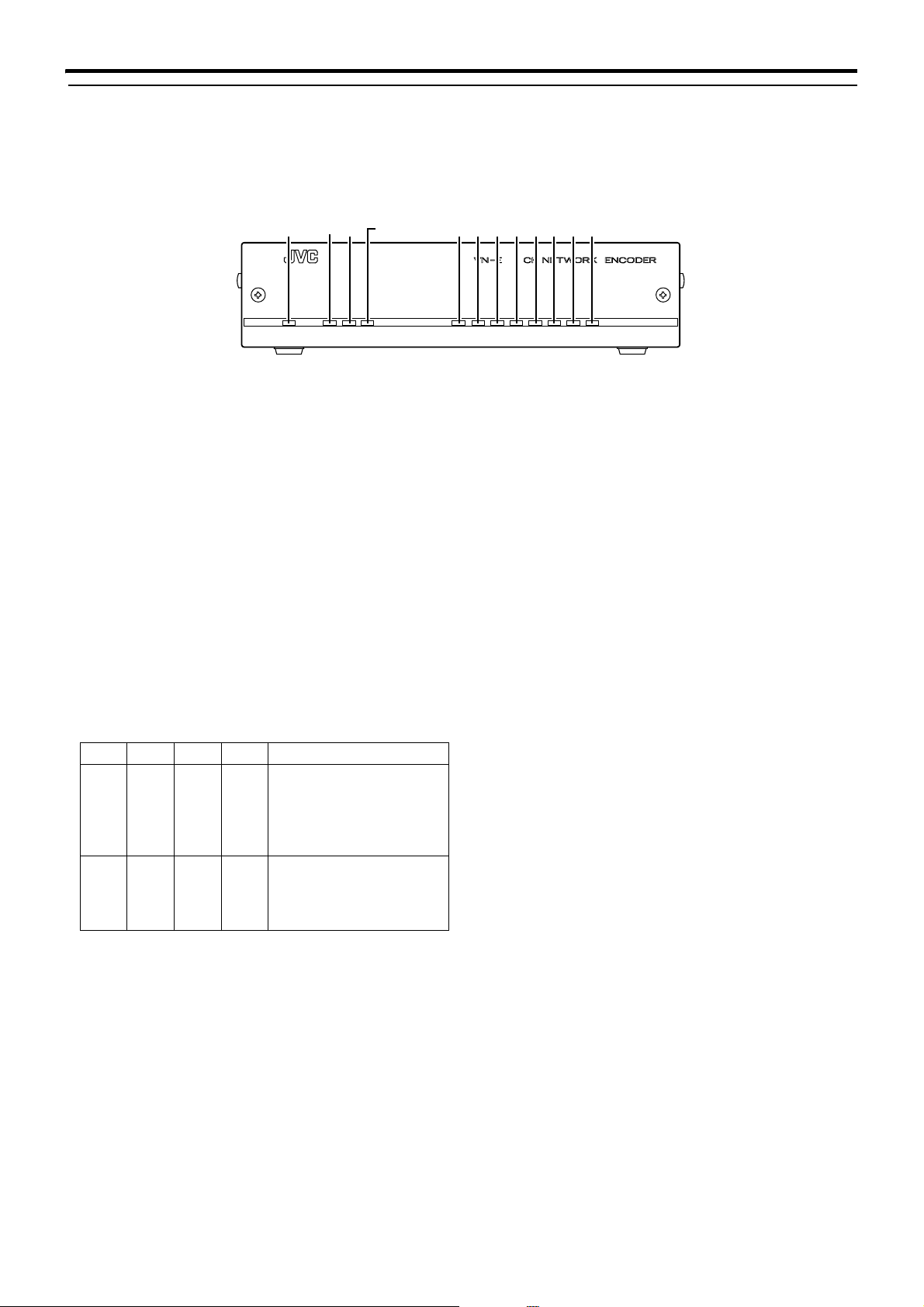
[FRONT]
A
B
C
DE
/COL
A [POWER]Lamp
Lights up when the power of VN-E4 is turned on.
B [LINK]Lamp
Lights up when VN-E4 is connected to the network.
C [100M]Lamp
Lights up when VN-E4 is connected to the network via
100Base. The light will not be illuminated in the case of
10Base.
D [FDX/COL]Lamp
Lights up when VN-E4 is connected to the network via full
duplex. The light will not be illuminated in the case of half
duplex. The light will appear blinking when collision occurs.
E [STS]Lamp (Status Lamp)
Lights up when VN-E4 is started up properly. The light will
appear blinking when troubles occur during startup and the
error details will be displayed in [CH1-CH4].
CH1 CH2 CH3 CH4 Error Details
Light
OFF
Light
OFF
Light
OFF
Light
OFF
Light
OFF
Light ONLight
Light
ON
OFF
A device with the same IP
address as VN-E4 is
detected. The lamps will
not change until the power
of VN-E4 is turned off.
There is no video signal
input to VN-E4. The normal
display will be restored
upon input of video signals.
F
GHIJKL
STS CH4CH3CH2CH1AUDO.LALMFDX100MLINKPOWER
F [ALM]Lamp (Alarm Lamp)
Displays alarm input to VN-E4. Lights up when there are
changes in the alarm input or when motion is detected. The
light will turn off automatically after 5 seconds.
G [O.L]Lamp (Overload Lamp)
Displays the processing load of VN-E4. This light is turned
off when this unit is functioning properly. This light is turned
on when the processing load of VN-E4 is too heavy.
H [AUD]Lamp (Audio Lamp)
Displays the audio transmission status of VN-E4. Lights up
during transmission of audio data to the network. Turns off
when there is no transmission.
I [CH1]Lamp (Video 1 Channel Lamp)
Displays the image transmission status of VN-E4. Lights up
during transmission of video input at [CH1] to the network.
Turns off when there is no transmission.
J [CH2]Lamp (Video 2 Channel Lamp)
Displays the image transmission status of VN-E4. Lights up
during transmission of video input at [CH2] to the network.
Turns off when there is no transmission.
K [CH3]Lamp (Video 3 Channel Lamp)
Displays the image transmission status of VN-E4. Lights up
during transmission of video input at [CH3] to the network.
Turns off when there is no transmission.
L [CH4]Lamp (Video 4 Channel Lamp)
Displays the image transmission status of VN-E4. Lights up
during transmission of video input at [CH4] to the network.
Turns off when there is no transmission.
8
Page 9

Introduction (continued)
Y
[BACK] [BOTTOM]
R
CONTROL
SERVICE
OUTPUT
S
COM OUT
10BASE-T/100BASE-TX
U
OUT
M
1CH
3CH
VIDEO INPUT
O
2CH
RS-485
RS-232C
4CH
PQ
COM1
COM2
AUDIO
IN
N
M [AUDIO IN] terminal (RCA pin)
For input of audio signals.
N [AUDIO OUT] terminal (RCA pin)
For output of audio signals.
O [VIDEO INPUT 1CH to 4CH] terminal (BNC)
For input of video signals.
P [RS-232C/RS-485] COM1, 2 Protocol Selection
Switch
For switching between RS-232C and RS-485 of COM1 and
COM2. Factory setting is RS-232C.
Q [COM1, COM2] terminal (D-sub 9P)
Serial port for controlling external devices.
R [CONTROL/SERVICE] switch
Switch for switching COM1 to servicing. Select CONTROL
for normal use. Select SERVICE during maintenance.
Factory setting is CONTROL.
S [ALARM OUTPUT] terminal
The COM and OUT terminals form the make contact. Alarm
output changes to break upon turning off the power of
VN-E4, and alarm output is restored to the previous state
upon turning on the power again.
TW
ALARM
1234 G
PUSH
RESET
V
INPUT
DC 5V
X
T [ALARM INPUT] terminal
Input terminal for no-voltage make contact or break contact.
This consists of 4 input and 1 ground terminals.
U [10 BASE-T/100 BASE-TX] LAN terminal
For connecting the network cable.
V [RESET] button
Button for resetting VN-E4. Power will be reset upon
pressing this button and releasing it within 5 seconds. If this
button is pressed for 5 seconds or longer, LEDs from STS
to CH4 will start to blink and all settings will be restored to
their factory defaults.
W Wire Clamp
For securing the cable of the AC adaptor.
X [DC 5V] Power Terminal
For connecting the AC adaptor supplied.
VN-E4 does not come with a power switch. It will start up
automatically upon supply of power using the AC adaptor.
Y The MAC address of VN-E4 is displayed on the
label in hexadecimal numbers.
9
Page 10
Preparation
1. System Setup Examples
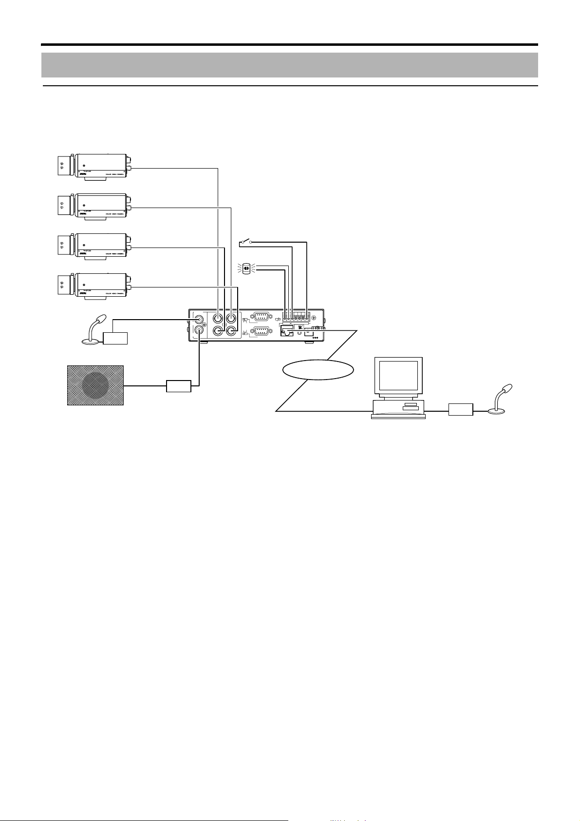
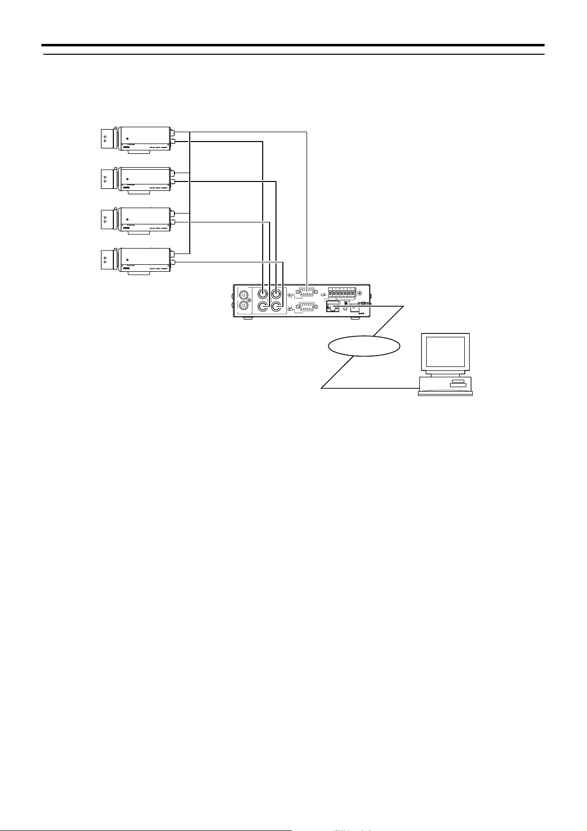
䡵1-1 Remote monitoring using the built-in viewer
The built-in viewer of VN-E4 can be used to enable remote monitoring via the PC.
Camera 1
LH
LEVEL
ALC
Av Pk
Camera 2
LH
LEVEL
ALC
Av Pk
Camera 3
LH
LEVEL
ALC
Av Pk
Camera 4
LH
LEVEL
ALC
Av Pk
Microphone
VIDEO IN 1
VIDEO IN 2
VIDEO IN 3
VIDEO IN 4
Amplifier
AUDIO IN
AUDIO
IN
1CH
OUT
3CH
AUDIO OUT
VIDEOINPUT
Sensor
Lamp
COM OUT
2CH
RS-485
RS-232C
4CH
ALARM
INPUT/G
COMOUT
1234G
PUSH
RESET
ALARM
INPUT
DC5V
CONTROL
SERVICE
COM1
OUTPUT
COM2
10BASE-T/100BASE-TX
Network
Network
Amplifier
Amplifier
Speaker
PC
Microphone
In addition to monitoring images of the 4 channels, bi-directional audio conversation is also possible.
When there is alarm input and detected motion, these will be displayed on the viewer. A warning light may be connected to the
alarm output terminal, which may be illuminated upon alarm input.
Images that are currently displayed may be captured in the PC’s hard disk.
10
Page 11
Preparation (continued)
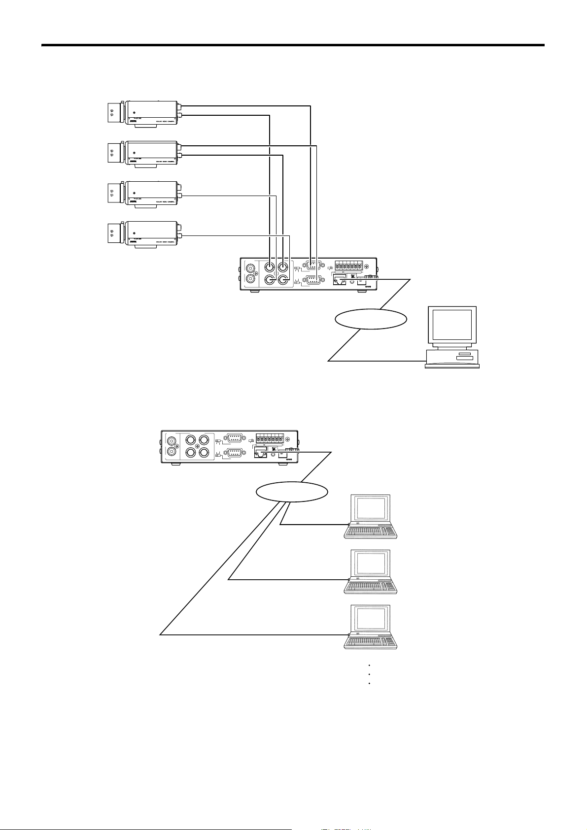
● Remote control of JVC cameras
Remote control of the following JVC cameras is possible using the viewer.
TK-C655E TK-C676E TK-C1480BE/C1460BE
LH
Av Pk
LH
Av Pk
LH
Av Pk
LH
Av Pk
LEVEL
ALC
LEVEL
ALC
LEVEL
ALC
LEVEL
ALC
Camera 1
Camera 2
Camera 3
Camera 4
Com 1
VIDEO IN 1
Com 2
VIDEO IN 2
VIDEO IN 3
VIDEO IN 4
VIDEOINPUT
AUDIO
IN
OUT
2CH
1CH
3CH
RS-232C
4CH
CONTROL
SERVICE
COM1
OUTPUT
RS-485
COM2
10BASE-T/100BASE-TX
ALARM
1234G
COMOUT
INPUT
PUSH
RESET
DC5V
Network
Network
PC
● Multi-point monitoring via multicast
Monitoring of multiple points is possible via multicast.
VIDEOINPUT
AUDIO
IN
OUT
IGMP Compliant Network
2CH
1CH
3CH
RS-485
RS-232C
4CH
CONTROL
SERVICE
COM1
OUTPUT
COM2
10BASE-T/100BASE-TX
ALARM
1234G
COMOUT
INPUT
PUSH
RESET
DC5V
Network
Network
PC
PC
PC
11
Page 12
Preparation (continued)
䡵1-2 Systems that combine other manufacturer’s devices
● Remote control of cameras that support Pelco-D protocol
Remote control of cameras that support the Pelco-D protocol is possible using the built-in viewer.
Camera 1
LH
LEVEL
ALC
Av Pk
Camera 2
LH
LEVEL
ALC
Av Pk
Camera 3
LH
LEVEL
ALC
Av Pk
Camera 4
LH
LEVEL
ALC
Av Pk
VIDEO INPUT 1~4
AUDIO
IN
OUT
2CH
RS-485
RS-232C
4CH
Com 1 (RS-485)
CONTROL
SERVICE
COM1
COM2
1234G
COMOUT
OUTPUT
10BASE-T/100BASE-TX
Network
Network
ALARM
INPUT
PUSH
RESET
DC5V
VIDEOINPUT
1CH
3CH
PC
12
Page 13
Preparation (continued)
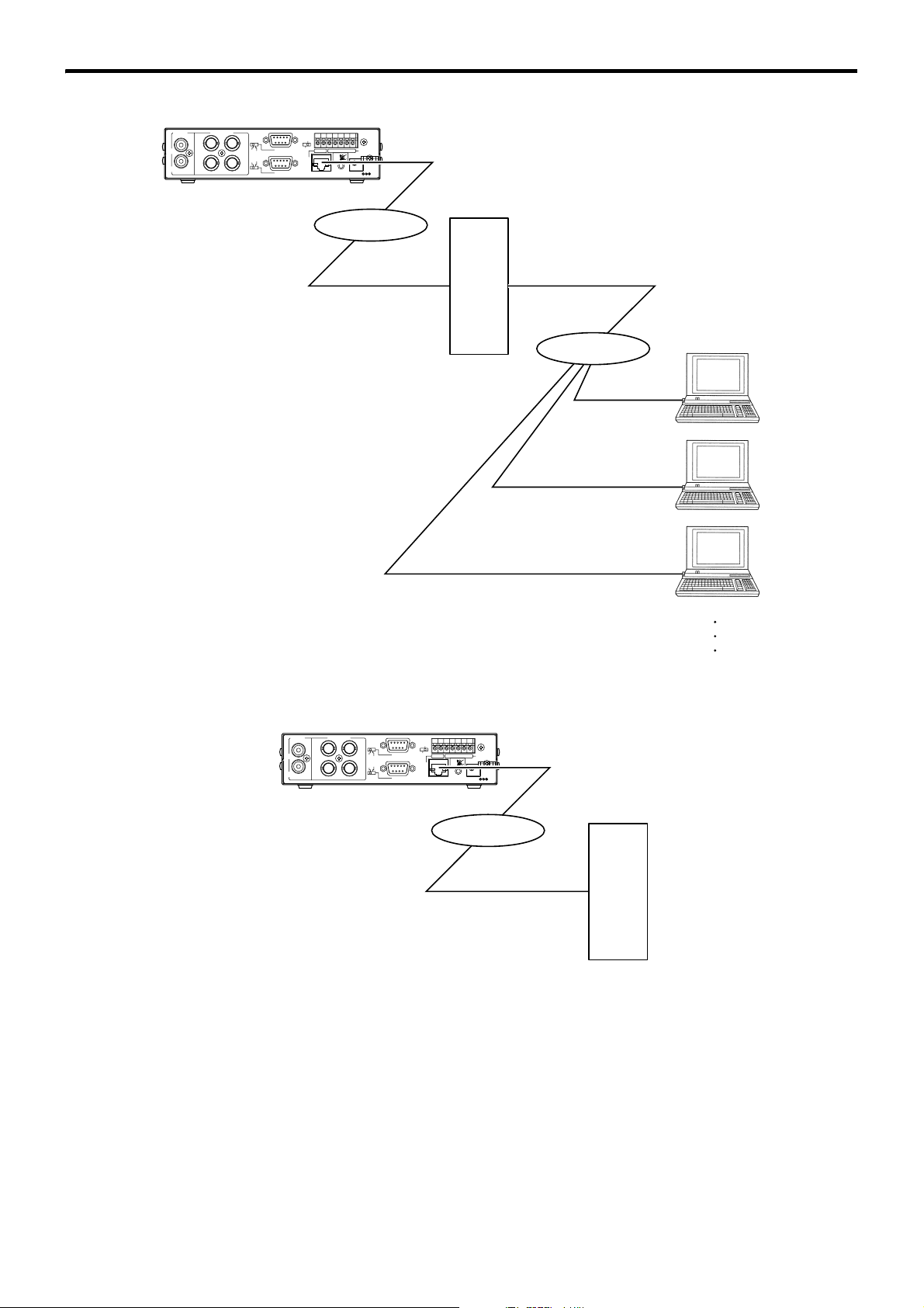
● Mass distribution via redistribution server
Images of VN-E4 may be recorded in the redistribution server and distributed to a large number of clients.
VIDEOINPUT
AUDIO
IN
OUT
2CH
1CH
3CH
RS-232C
4CH
CONTROL
SERVICE
COM1
OUTPUT
RS-485
COM2
10BASE-T/100BASE-TX
ALARM
1234G
COMOUT
INPUT
PUSH
RESET
DC5V
Network
Network
SERVER
Network
Network
PC
PC
PC
● Recording images at the FTP server
FTP can be set such that JPEG files are transferred from VN-E4 to FTP server when alarm occurs. Images before and after
the alarm input time (pre/post images) may be recorded at the FTP server.
VIDEOINPUT
AUDIO
IN
OUT
2CH
1CH
3CH
RS-232C
4CH
CONTROL
SERVICE
COM1
OUTPUT
RS-485
COM2
10BASE-T/100BASE-TX
ALARM
1234G
COMOUT
INPUT
PUSH
RESET
DC5V
Network
Network
FTP
SERVER
● Control via customized application software
The following uses are also possible by developing a customized application software that supports the API of VN-E4.
Monitoring via the PC while at the same time recording images/audio to the HDD.
Recording by increasing the frame size/frame rate during alarm occurrence.
Recording the type and time of alarm occurrence at the PC.
Remote control of some external devices using the pass-through feature of VN-E4.
13
Page 14

Preparation (continued)
2. Requirements for network using VN-E4
䡵2-1 Network Bandwidth
Ensure that there is sufficient network bandwidth for the data volume to be transmitted by VN-E4. Data volume to be transmitted
by VN-E4 varies with the number of image or audio distributions.
● Data volume of images
VN-E4 enables creation of up to 8 different types of images.
Input CH Frame Size
No. 1 CH1 VGA
No. 2 CH1 QVGA
No. 3 CH2 VGA
No. 4 CH2 QVGA
No. 5 CH3 VGA
No. 6 CH3 QVGA
No. 7 CH4 VGA
No. 8 CH4 QVGA
VN-E4 allows distribution of each image to multiple destinations. Data of image to be transmitted by VN-E4 is therefore the
aggregate total of all these data.
Data volume of No. 1 L no. of distributions + data volume of No. 2 L no. of distributions +...+ data volume of No. 8 L no. of
distributions
The number of distributions shall be the total number of stream transmissions via TCP (number of clients) and multicast.
(Example)
Data volume will be calculated according to the formula below when 3 streams of No. 1 are sent.
JPEG file size per frame L frame rate L 3
If the JPEG file size per frame is 30 KB and frame rate is 30 fps, then data volume will be as follows.
30 KB L 30 fps L 3 = 2700 KB/sec = Approx. 21 Mbps
The JPEG file size per frame varies with the parameter set as well as input video signals. The following table may be used as a
reference.
Picture Quality Control Method VGA File Size QVGA File Size
1 (High) 80 KB 27 KB
2 60 KB 20 KB
3 40 KB 13 KB
VFS (Variable File Size)
AFS (Average File Size)
CFS (Constant File Size)
● Audio data volume
Audio data transmitted by VN-E4 is at 64 kbps per stream. Audio data volume may be calculated using the following formula.
64 kbps L no. of streams
The number of streams is the total number of streams sent via TCP (number of clients), streams sent via multicast, and stream
received by VN-E4.
(Example)
When VN-E4 sends out 2 audio streams and receives 1 audio stream, data volume will be as follows.
64 kbps L 3 = 192 kbps
4 (Medium) 30 KB 10 KB
5 25 KB 8 KB
6 20 KB 7 KB
7 (Low) 15 KB 5 KB
Selection may be made from the
range between 10 to 100 KB
Selection may be made from the
range between 10 to 100 KB
Selection may be made from the
range between 3 to 33 KB
Selection may be made from the
range between 3 to 33 KB
NOTE:
When there is insufficient network bandwidth, the number of JPEG frames (frame rate) that may be acquired by the client will
decrease.
In addition, delay time will be prolonged and interruptions will also occur in the audio data.
14
Page 15

Preparation (continued)
䡵2-2 Network Delay
When the client acquires JPEG or audio via TCP, VN-E4 will be send out data while checking the ACK from the client at the same
time. For networks with considerable delay, data cannot be sent out until ACK is received, and therefore the frame rate will drop.
To operate VN-E4 and its built-in viewer using the factory settings, the frame rate will drop below 120 fps if the round trip time
exceeds 4 msec. Enlarging the window scale of the PC on which the built-in viewer is running may extend the round trip time for
which frame rate deteriorates to 20 msec. Refer to the section on A7. TroubleshootingB in AOthersB for details on the window scale.
Drop of frame rate by network delay can be eliminated by using multicast.
䡵2-3 Network Jitter
When there is considerable network jitter, delay time may be prolonged, frame rate may drop and audio sound may be
interrupted.
There are 3 types of buffer that may be chosen for the built-in viewer, namely 0.3, 0.6 and 1.0 second. Influences of jitter may be
reduced by setting to a larger value. In this case, however, delay time will be prolonged.
䡵2-4 Packet Loss
When acquiring images/audio from VN-E4 via TCP, packet loss may be recovered by resending from TCP. When there is
considerable delay during resending, however, image frame rate may drop and audio sound may be interrupted.
When packet loss occurs during multicast sending from VN-E4, image frame rate may drop and audio sound maybe interrupted.
䡵2-5 Use of Multicast
Make use of a network that supports IGMP if multicast is to be used. When a network that does not support IGMP or multicast
routing is used, multicast data that is sent out from VN-E4 may not reach the recipient and playback may fail.
15
Page 16

Preparation (continued)
3. IP Address Setting
䡵3-1 VN-E4 with Factory Default Settings
Refer to
START-UP GUIDE
on procedures for setting the IP address when VN-E4 is in the factory default settings.
䡵3-2 VN-E4 for which IP address is known
When the IP address of VN-E4 is known, it can be changed by accessing the built-in web page of VN-E4 via the PC’s Internet Explorer.
See A5. Setting Using Internet ExplorerB.
䡵3-3 When IP address of VN-E4 is unknown
When IP address of VN-E4 is unknown, there are 3 methods to know IP address.
a) Use the search tool
The search tool in attached CD-ROM is available to know IP address of VN-E4. Refer readme file of the tool for detailed
information.
b) Initialize VN-E4
Pushing [RESET] button on rear panel over 5 seconds initializes VN-E4 to factory default setting.
c) Capture packets on network
Perform following procedures to find out the IP address of VN-E4.
1. Configuration for looking up IP address
Set up a PC with the network monitor software installed on it. The network monitor software will capture and look up incoming
packets at the PC. An example of free network monitor software that may be obtained from the Internet is Ethereal.
Connect VN-E4, the switching hub and PC using a straight LAN cable of Category 5 and above. (Do not connect the DHCP
server to the switching hub.)
2. Capturing packets sent by VN-E4
Launch the network monitor software on the PC and start capturing.
Supply power to VN-E4 using the AC adaptor. Depending on the settings, the amount of time required for VN-E4 to start up may
vary from about 1 to 2 minutes. VN-E4 will start packet transmission during this interval, and capturing will end in about 2 minutes.
3. Looking up captured packets
● If ARP request is sent first by VN-E4
If the following ARP request is sent first by VN-E4, then the destination IP address of this packet will be the IP address of
VN-E4. (In this case, the subnet mask of VN-E4 is unknown.)
Packet type: ARP request
Source IP address: 100.100.254.169
This ARP request packet is used to check whether there are devices that possess a duplicate IP address with VN-E4. In this
case, ADHCPB and APPPoEB of VN-E4 are set to AOffB.
● If the DHCP Discover packet is sent first by VN-E4
The DHCP client function of VN-E4 is set to ON. In a LAN environment without a DHCP server, the DHCP will time out in
about 2 minutes after the power is turned on, and VN-E4 will be started up using the following IP address.
IP address 192.168.0.2
Subnet mask 255.255.255.0
Default gateway 192.168.0.254
● If the following broadcast packet is sent first by VN-E4
Destination MAC address 0xFFFFFFFFFFFF
Ethernet Type 0x8863
The APPPoEB of VN-E4 is set to AOnB. In a LAN environment without a PPPoE server, it will time out in about 2 minutes after
the power is turned on, and VN-E4 will be started up using the following IP address.
IP address 192.168.0.2
Subnet mask 255.255.255.0
Default gateway 192.168.0.254
4. IP address setting on PC
The subnet mask of VN-E4 is unknown when methods 1. to 3. are used to look up the IP address, and there is a possibility
that this may be 255.255.255.254.
Set the IP address of the PC such that it is in the same segment with VN-E4.
(Example 1) When the IP address of VN-E4 is 10.1.2.2
By setting the PC’s IP address to 10.1.2.3 and the subnet mask to 255.255.255.0, they will be in the same segment and
communication will be enabled even if the subnet mask of VN-E4 is 255.255.255.254.
(Example 2) When the IP address of VN-E4 is 10.1.2.3
By setting the PC’s IP address to 10.1.2.2 and the subnet mask to 255.255.255.0, they will be in the same segment and
communication will be enabled even if the subnet mask of VN-E4 is 255.255.255.254.
Whether communication is enabled may be determined by sending a Ping from the PC to the IP address of VN-E4.
For procedures on changing settings of VN-E4 via Internet Explorer on the PC, refer to A5. Setting Using Internet ExplorerB.
16
Page 17
Preparation (continued)
4. Connection / Installation
䡵4-1 AC Adaptor
Connect the AC adaptor cable to the power terminal of VN-E4, followed by securing the cable using the wire clamp. Plug the
power cable into the AC adaptor, followed by the power cable plug to the power source.
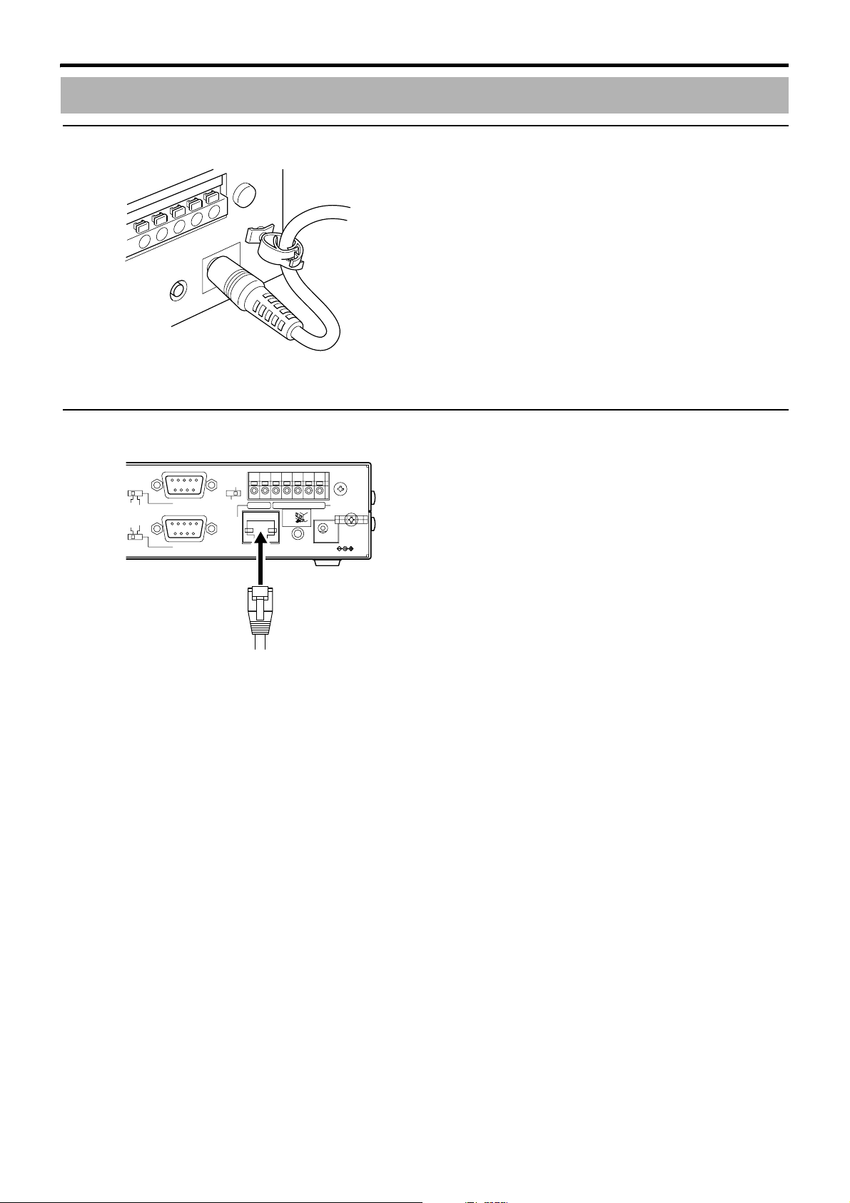
䡵4-2 Network
RESET
ALARM
INPUT
DC 5V
RS-485
RS-232C
COM1
COM2
CONTROL
SERVICE
OUTPUT
1234 G
COM OUT
PUSH
10BASE-T/100BASE-TX
Connect VN-E4 to the switching hub using a straight LAN cable of Category 5 and above.
17
Page 18

Preparation (continued)
E
M
A
I
䡵4-3 [COM1,2] Serial Port Terminals
CONTROL
SERVICE
2CH
RS-232C
4CH
COM1
RS-485
COM2
Connect the device (camera, etc.) to be controlled to the serial port. Use the switch to switch between RS-232C and RS-485.
● Pin Layout
Pin No.
1 (NC) (Not in use) RX+ + Receiving End
2 RXD Receive data RX -- Receiving End
3 TXD Send data TX -- Sending End
4 (NC) (Not in use) TX+ + Sending End
5 GND Grounding GND Grounding
6 (NC) (Not in use) (NC) (Not in use)
7 (NC) (Not in use) (NC) (Not in use)
8 (NC) (Not in use) (NC) (Not in use)
9 (NC) (Not in use) (NC) (Not in use)
CO
OUTPUT
10BAS
When RS-232C is selected When RS-485 is selected
Name Function Name Function
䡵4-4 Alarm Input
RESET
ALARM
INPUT
DC 5V
CONTROL
SERVICE
OUTPUT
1234 G
COM OUT
PUSH
10BASE-T/100BASE-TX
For connecting the sensor. This consists of 4 input and 1 ground terminals. Either Make or Break is selected depending on the
setting, and sensors of the no-voltage A contact output (normally open), no-voltage B contact output (normally closed) or novoltage C contact output type may be used.
䡵4-5 Alarm Output
CONTROL
SERVICE
COM1
OUTPUT
COM2
The [OUT] and [COM] terminals form the make contact. Connect the device that is to be turned on during an alarm. Alarm output
changes to break when the power of VN-E4 is turned off. Upon starting up VN-E4, the alarm output is restored to the previous
state.(A pg. 54, A8. SpecificationsB)
1234 G
COM OUT
PUSH
10BASE-T/100BASE-TX
RESET
DC 5V
18
Page 19

Preparation (continued)
䡵4-6 AV Devices
1CH
VIDEO INPUT
2CH
AUDIO
IN
RS-232C
OUT
3CH
4CH
Connect up to 4 cameras to the 4 video input terminals at the rear panel of VN-E4. Output signals of each camera need not be
synchronized.
Connect a microphone to the audio input terminal at the rear panel of VN-E4 via amplifier.
Connect a speaker to the audio output terminal at the rear panel of VN-E4 via amplifier.
䡵4-7 Attaching Rack Mount Brackets
The rack mount brackets (optional) can be used to install the unit to a rack. Request installation to the dealer of purchase.
* For details concerning the rack mount brackets, please consult the person in charge of professional equipment at your nearest
JVC-authorized service agent.
In case of 1 unit. (VN-BK10 rack mount bracket)
1. Mount the side bracket on both left and right
(Remove 1 screw from each end of VN-E4. Fasten each
end using 1 M3 screw and 2 M4 screws that are supplied
2.
1.
P
O
W
E
R
L
I
N
K
1
0
0
M
FD
X
/
C
O
L
S
TS
A
L
M
O
.
L
A
U
D
CH
1
CH
2
CH
3
CH
4
1.
with the rack mount bracket.)
2. Fasten to the rack using the M5 screws supplied with
the rack mount bracket
(2 M5 screws at each end)
2.
In case of 2 units. (VN-BK11 rack mount bracket)
1. Mount the joint bracket to the connecting face of the
2.
3.
unit
(Remove 3 screws from VN-E4. Connect with 3 M3 screws
that are supplied with the rack mount bracket.)
2. Fasten the 4 locations (top and bottom) using the M3
4.
0
0
M
F
D
X
/
C
O
L
S
T
S
A
L
M
O
.
L
A
U
D
C
H
1
C
H
2
C
H
3
C
H
4
1.
P
OW
E
R
L
IN
K
1
00
M
F
D
X
/C
O
L
S
T
S
A
L
M
O
.
L
A
U
D
C
H
1
C
H
2
C
H
3
C
H
4
3.
4.
2.
screws supplied with the rack mount bracket
(For joining the left and right units)
3. Mount the side bracket on both left and right
(Remove 1 screw from each end of VN-E4. Fasten each
end using 1 M3 screw and 2 M4 screws that are supplied
with the rack mount bracket.)
4. Fasten to the rack using the M5 screws supplied with
the rack mount bracket
P
O
WE
R
L
IN
K
1
(2 M5 screws at each end)
䡵4-8 Connection with PC
Connect the PC to the switching hub using a straight LAN cable.
To operate the built-in viewer of VN-E4, set up the PC as follows.
[Recommended PC Specifications for Viewing]
OS : Windows XP Pro (SP2) or Windows XP Home (SP2)
CPU : For receiving at 30 fps: 1.5 GHz
For receiving at 120 fps: 3.4 GHz
Memory : 1 GB
Hard disk : Free disk space of 20 MB and above
Video card : 1024 L 768 pixels or higher, True Color (24 or 32 bits)
Sound card : Sound Blaster (PCI)
Web browser : Internet Explorer V6.0
19
Page 20

Settings
5. Setting Using Internet Explorer
1. Setting Up of PC for Setting
Setting of VN-E4 may be performed using Internet Explorer. Refer to ASTART-UP GUIDEB on the PC specification
requirements, and setting of PC’s IP address as well as Internet Explorer.
2. Enter user name and password
User name and password entry will be required at the beginning. There are 3 access authorization levels to VN-E4. Factory
settings of the unit are as follows.
User Name Default Password Description
admin vn-e4 All operations and changes are allowed.
operator vn-e4 Change of settings other than those related the network are allowed.
user vn-e4 Viewing of input images and change of language on setting pages are allowed.
NOTES:
A security warning window will appear during access. Press the AOKB button to proceed.
If you do not want this warning window to be displayed, change the Internet Explorer settings as follows.
Open
ATo ol s B
-
AInternet OptionsB
UP GUIDE. Press
A
Custom LevelB
3. The JPEG View page (top page) will be displayed
-
ASecurityB
button to select
, select ATrusted sitedB
icon, that you might registered VN-E4 URL according to START-
AEnableB in the ADisplay mixed contentB item under AMiscellaneousB.
This top page will be displayed upon access via AadminB, AoperatorB or AuserB. The video input image at the point when this
page is opened will be displayed as a still image.
Available links and buttons are depends on user name, i.e. AadminB, AoperatorB or AuserB.
20
Page 21

Settings (continued)
䡵5-1 JPEG View Page (Top Page)
Links to each page are located on the left. Links that are displayed vary accordingly with the user name. For example, in the case
of AadminB or AoperatorB, 3 links, namely AJPEG ViewB, AInputB and AEncodingB will be displayed upon clicking AImage & AudioB. In
the case of AuserB, only AJPEG ViewB is displayed.
Pages that users have access to
admin operator user
Image & Audio Image & Audio Image & Audio
JPEG View JPEG View JPEG View
Input Input
Encoding Encoding
External External
Alarm Alarm
Alarm Environment Alarm Environment
Serial Port Serial Port
Network Network
Basic Streaming
Details
Streaming Utility
Access Restrictions Miscellaneous Utility
Time Miscellaneous
Password Status
Operation
Utility Settings
Maintenance
Miscellaneous
Status
Operation
Settings
21
Page 22

Settings (continued)
A
B
C
A Switching Language Click AJapanese / EnglishB at upper right to switch the display language of the web page.
B Reload Button Press this button to refresh the JPEG image displayed.
Clicking AJPEG ViewB or re-entering the Internet Explorer address will only display the page that
is temporarily stored in the Internet Explorer, and JPEG images may not be refreshed in this
case. To refresh JPEG images using the above operations, change the Internet Explorer settings
as follows.
Open ATo ol s B - AInternet OptionsB, and click the ASettingsB button under Temporary Internet Files.
Select AEvery visit to the pageB.
C Viewer... Button This is displayed upon access to the AJPEG ViewB page via AadminB or AoperatorB. Click this
button, and click AOKB button on displayed security alarm window to launch the built-in viewer.
Do not click this button again leaving the security alarm window. The motion detect setting
window on the AAlarm EnvironmentB page and the built-in viewer cannot be launched at the
same time.
When this button is pressed for the first time on the operating PC, the built-in viewer will be
installed on the PC. Refer to ASTART-UP GUIDEB on procedures to install the built-in viewer on
the PC. Refer to ASTART-UP GUIDEB on basic operations of the built-in viewer. Refer to A6. Using
the VN-E4 Built-in ViewerB on further details on the uses of the built-in viewer.
22
Page 23

Settings (continued)
䡵5-2 Input Page
This page is for setting the video and audio input parameters.
A B C D E F
G
This page can be used upon access via AadminB or AoperatorB. Press the AOKB button to enable the new settings upon changing. If
the AOKB button is pressed upon entering an invalid value, a warning message will appear and entry will be denied. Press the
ACancelB button to restore the invalid entry to the current value.
A Camera Name Texts entered here is stored in the JPEG comment segment. Refer to AAPI GUIDEB on file
format of VN-E4 JPEG.
B Brightness For adjusting brightness. Setting range is between 0 and 100.
C Contrast For adjusting contrast. Setting range is between 0 and 100.
D Saturation For adjusting color saturation. Setting range is between 0 and 100.
E Phase For adjusting hue. Setting range is between 0 and 100.
F Turn over For flipping the image upside down.
NOTE:
The Flag specified here is stored in the JPEG comment segment. Switching this parameter does
not invert image data itself in JPEG. Refer to AAPI GUIDEB on file format of VN-E4 JPEG.
G Echo Suppressor For reducing audio echo. Use this when bi-directional audio is used.
H Noise Suppressor For reducing the noise in audio data that is input to VN-E4. Audio output from VN-E4 will not be
affected. Enhancing the setting may increase the effectiveness of removing noises, but it also
comes with a trade-off of deterioration in sound quality.
H
23
Page 24

Settings (continued)
䡵5-3 Encoding Page
This page is for setting JPEG encoding parameters.
A B C D
This page can be used upon access via AadminB or AoperatorB. Press the AOKB button to enable the new settings upon changing. If
the AOKB button is pressed upon entering an invalid value, a warning message will appear and entry will be denied. Press the
ACancelB button to restore the invalid entry to the current value.
A Encode Number Up to 8 types of encoding are possible using different combinations of the input channel and
frame size. Turn on the check box for items to be used. Deselect unnecessary items to enable
effective allocation of the processing capacity of VN-E4.
B Quality For specifying the rate control mode and target file size.
When A1-high-B to A7-high-B is selected, the quantization table of JPEG encoding is fixed and the
file size will increase/decrease according to the input signals. Default value of each option is
displayed in the target file size. Be careful when recording JPEG data to a recorder with limited
recording capacity, as file sizes may increase or decrease, so the maximum recording time may
be changed (When AAverage File SizeB or AConstant File SizeB is selected, input of target file size
will be enabled.)
WhenAAverage File SizeB is selected, encoding is performed such that average file size of
multiple JPEG images becomes the target file size.
WhenAConstant File SizeB is selected, encoding is performed such that each JPEG file size
becomes the target file size. When AConstant File SizeB is selected, the processing load of
VN-E4 is heavy and the maximum frame rate becomes a quarter of the maximum frame rate in
other rate control modes
C Frame Rate For specifying the number of frames to encode per second. VN-E4 is limited in its processing
capacity and the specified frame rate may not be realized depending on the settings of
AEncode NumberB and AQualityB.
In particular, when AConstant File SizeB is selected or when the target file size is set to a large
value, the upper limit of AFrame RateB will be lowered.
An example of settings for which 120 fps (VN-E4U) or 100 fps (VN-E4E) can be realized is as
follows.
Encoding : 4 VGA set to ON
Quality : AAverage File SizeB selected and set to A24KBB
Frame Rate : A30B(VN-E4U), A25B(VN-E4E)
The unit will function as follows if the frame rate is altered when data distribution is in progress.
When frame rate is increased When frame rate is decreased
Frame rate of the distribution remains
Distribution via TCP
Distribution via Multicast
D Interpolate When AInterpolateB is off, video frame with 480 horizontal lines is encoded to JPEG. When
AInterpolateB is on, video field with 240 horizontal lines is interpoleted to 480 horizontal lines, and
encoded to JPEG. To get high resolution, AOffB is recommended. To avoid jaggy image caused
by fast moving objects, AOnB is recommended.
unchanged.
Frame rate of the distribution
increases accordingly with the new
settings.
Frame rate of the distribution
decreases accordingly with the new
settings.
Frame rate of the distribution
decreases accordingly with the new
settings.
24
Page 25

Settings (continued)
䡵5-4 Alarm Page
This page is for setting actions when there is an alarm. Up to 10 actions may be set.
This page can be used upon access via AadminB or AoperatorB. Press the AOKB button to enable the new settings upon changing. If
the AOKB button is pressed upon entering an invalid value, a warning message will appear and entry will be denied. Press the
ACancelB button to restore the invalid entry to the current value.
A
A Action For specifying the type of action.
Disable : Do not invoke action.
Mail : Specify the mail address of the destination. An action number will be added to
the mail subject, as shown in the following example.
Alarm from VN-E4: No. 1
To attach a message to the mail, enter the message in AMail CommentB.
Refer to A5-5 Alarm Environment PageB for mail environment settings.
FTP : FTP the JPEG as specified in AInput SourceB. Refer to A5-5 Alarm
Environment PageB for FTP environment settings. FTP can be set on only 1
action out of the 10 actions.
TCP : Send message entered in the ATCP/UDP CommentB field to the destinations
specified in AIP AddressB and APort NumberB via ATCPB.
UDP : Send message entered in the ATCP/UDP CommentB field to the destinations
specified in AIP AddressB and APort NumberB via AUDPB.
Pin Output Make : Change alarm output to Make. Refer to A5-5 Alarm Environment PageB on
parameter settings for alarm output.
Pin Output Break: Change alarm output to Break. Refer to A5-5 Alarm Environment PageB on
parameter settings for alarm output.
B 1st Trigger For specifying the first trigger to invoke the action. Either alarm input (make), alarm input (break)
or motion detect can be selected. Refer to A5-5 Alarm Environment PageB on parameter settings
for alarm input. When the second trigger is turned off, the action will be invoked by only the first
trigger. In addition, when motion detection is selected as the first trigger, AMax. IntervalB and
A2nd TriggerB will not be available for selection, and only the first trigger will function.
C Max. Interval Valid only when the second trigger is specified. For specifying the maximum interval between the
first and second triggers. Action will be invoked when second trigger occurs after first trigger
within the maximum interval.
D 2nd Trigger For specifying the second trigger to invoke the action. Either alarm input (make) or alarm input
(break) can be selected. Unlike the first trigger, motion detect is not available as a choice. Refer
to A5-5 Alarm Environment PageB on parameter settings for alarm input.
B
C
D
25
Page 26

Settings (continued)
䡵5-5 Alarm Environment Page
This page is for setting alarm-related environments.
A
B
This page can be used upon access via AadminB or AoperatorB.
Press the AOKB button to enable the new settings upon changing. If the AOKB button is pressed upon entering an invalid value, a
warning message will appear and entry will be denied. Press the ACancelB button to restore the invalid entry to the current value.
A Mail For setting the mail environment when AMailB is specified as an action of the AAlarmB page.
ASMTPB and APOPB can be used.
B FTP For setting the FTP environment when AFTPB is specified as an action of the AAlarmB page.
When ADirectoryB is left blank, FTP transfer will be performed to the home directory of the FTP
server. To enable FTP transfer to a directory below the home directory, set the directory name in
ADirectoryB. Delimit the directory using A/B.
Example) subdir1/subdir2
Destination directory of FTP transfer will be dependent on the FTP server if / is added at the
beginning.
AFrame RateB will be constrained by the frame rate as set on the AEncodingB page. The actual
frame rate used for transmission will be the upper limit on the AEncodingB page even if a value
that is larger than the frame rate in the AEncodingB page is specified. The upper limits of ABefore
TriggerB and AAfter TriggerB are determined by settings on the AEncodingB page. In addition,
AFrame RateB is in a trade-off relationship with ABefore TriggerB and AAfter TriggerB. In the case of
a combination such that the input value cannot be realized, adjustments will be automatically
made on the item that is not specified.
The name of the file to be transmitted via FTP is made up of the action number, year, month,
day, hour, minute, second, number and trigger flag.
Example: 01-20050711152904-001-0.jpg
The first 2 digits indicate the action number. Next 14 digits after first hyphen indicate the year,
month, day, hour, minute and second. The 3 digits after the second hyphen is the number of the
series of JPEG files to be sent via that FTP. The first file is numbered 000. The last digit denotes
the trigger flag. 0 is assigned to JPEG files before and after a trigger and 1 for the file when
trigger is invoked.
26
Page 27

Settings (continued)
C
D
E
F
G
A Chattering Guard Time Setting when alarm input is specified as a trigger of the AAlarmB page. The minimum event
interval can be specified for each alarm input.
B Output Duration For setting the output time when alarm output is specified as an action of the AAlarmB page.
C Manual Output For operating alarm output manually. The current output status will be displayed on the right. If
AOutput DurationB is zero, AMakeB button sets alarm output to be Make, and ABreakB button sets
alarm output to be Break. If AOutput DurationB is not zero, AMakeB button sets alarm output to be
Make, and to be Break after the Output Duration. ABreakB button sets alarm output to be Break,
and to be Make after the Output Duration.
D Motion Detection The window for setting the motion detect feature is displayed. For motion detect settings, there is
E Motion Detect Setting
Window
no need to press the AOKB button on the AAlarm EnvironmentB page. Additionally, the motion
detect setting window and built-in-viewer cannot be used at the same time.
The window for setting motion detect will be opened upon clicking ASetting Window...B on the
AAlarm EnvironmentB page. When the AoperatorB password is set in the motion detect setting
window, current settings are displayed in the window.
27
Page 28

Settings (continued)
A
D
E
F
G
H
B
A Operator Password The AoperatorB password is required to display current settings, or change current settings.
Enter the AoperatorB password and press the ASetB button.
The password is set to Avn-e4B in the factory settings. This can be changed on the APasswordB
page.
B CH1-CH4 Button Select a channel for setting.
C Display Screen For setting whether to mask each block upon dividing the screen into 12 x 12 blocks. In factory
settings, all blocks are masked.
The block turns blue when it is clicked, and it means unmasked. It returns to the normal state
upon clicking it again, and it means masked.
Press the ASendB button to validate current changes.
D Detection For setting motion detect to ON/OFF. To enable the setting, press the AMask AllB or ASendB
button.
E Sensitivity For setting the sensitivity of motion detect. To enable the setting, press the AMask AllB or ASendB
button.
F Motion For selecting the motion speed of the object for which motion is to be detected. To detect fast
motion, select AFas tB. To detect slow motion, select ASlowB. To enable the setting, press the
AMask AllB or ASendB button.
G Mask All Button Masks all blocks and enables the currentADetectionB, ASensitivityB and AMotionB settings.
H Send Button For enabling the current AMaskB, ADetectionB, ASensitivityB and AMotionB settings.
NOTE:
The area display serves as a reference. Ensure to perform operation check.
Ensure that multiple blocks are used to set the size of the object for motion detect.
C
The motion detect area will be displayed in blue.
CAUTIONS:
When a camera is connected, flicker of fluorescent lights may cause malfunction during motion detect.
Changes in brightness due to auto iris or lighting may be detected as motion.
The motion detect feature is not intended to prevent theft or fire. This feature may not function properly depending on conditions
of the object and settings. Our company shall not be liable for any accident or damage that occurs.
28
Page 29

Settings (continued)
䡵5-6 Serial Page
This page is for setting the 2 serial ports.
A
B
C
D
E
F
This page can be used upon access via AadminB or AoperatorB.
Press the AOKB button to enable the new settings upon changing. If the AOKB button is pressed upon entering an invalid value, a
warning message will appear and entry will be denied. Press the ACancelB button to restore the invalid entry to the current value.
A Controlled Device Select a device accordingly when an external device is to be controlled using the built-in viewer.
The ABaud RateB, AData LengthB, AParityB and AStop BitB settings will be automatically adjusted
according to the default values of the selected device.
When APelco- DB is selected for AControlled DeviceB, ACamera AddressB may be specified
individually for the 4 input channels.
B Baud Rate For setting the baud rate of the serial port.
C Data Length For setting the data length of the serial port.
D Parity For setting the parity bit of the serial port.
E Stop Bit For setting the stop bit of the serial port.
F Comment For writing memo. Comments will only appear when this page is displayed, and functions of the
serial port will not be affected.
29
Page 30

Settings (continued)
䡵5-7 Basic Page
This page is for performing basic setting related to the network.
A
B
C
D
E
F
G
H
I
J
This page can be used upon access via AadminB.
Press the AOKB button to enable the new settings upon changing. If the AOKB button is pressed upon entering an invalid value, a
warning message will appear and entry will be denied. Press the ACancelB button to restore the invalid entry to the current value.
When settings of the ABasicB page is changed, all services that are currently running will end immediately. For example, when
changes are made to the ABasicB page during JPEG or audio distribution, distribution will be discontinued and TCP will be
disconnected.
A IP Setting For setting the DHCP client function. Ensure to connect VN-E4 to a network environment with a
B IP Address For setting the IP address of VN-E4.
C Subnet mask For setting the subnet mask of VN-E4.
D Default Gateway For setting IPv4 default gateway of VN-E4. Default gateway of IPv6 can not be set. Set as
E Host Name For setting the host name of VN-E4.
F Domain Name For setting the domain name.
G DNS Server For setting whether to use the DNS/DDNS server as well as the corresponding server address.
H MAC Address The MAC address of VN-E4 is displayed in a hexadecimal number.
I IP Version For setting IPv6 to ON/OFF. (IPv4 is ON at all times.) When IPv6 is set to ON in a network that
J IPv6 Address Displays the IPv6 address.
DHCP server when enabling the DHCP settings. When a DHCP server is not present, VN-E4 will
start up using 192.168.0.2/24 about 2 minutes after the launch. Refer to A3. IP Address SettingB
for the IP address.
0.0.0.0 when a default gateway is not set.
Default gateway setting is required for multicast transmission. If default gateway does not exist,
set a dummy IP address as default gateway for sending multicast.
supports IPv6, the address will be displayed in the AIPv6 AddressB field. When the network does
not support IPv6, the AIPv6 AddressB field is displayed as ADisableB.
Changing this item restores AMTUB on the ADetailsB page to the default value of A1420B.
VN-E4 will reboot when this item is changed. Operation will be enabled after about 1 minute.
30
Page 31

Settings (continued)
䡵5-8 Details Page
This page is for performing detailed network setting.
A
B
C
D
E
This page can be used upon access via AadminB.
Press the AOKB button to enable the new settings upon changing. If the AOKB button is pressed upon entering an invalid value, a
warning message will appear and entry will be denied. Press the ACancelB button to restore the invalid entry to the current value.
A Image DSCP For setting the DSCP value of IP packets in which JPEG is stored. DSCP values are used in
networks that support QoS.
B Audio DSCP For setting the DSCP value of IP packets in which audio is stored. DSCP values are used in
C MTU For setting the maximum packet size for storing JPEG. The range of set value is between 512 to
D Negotiation For setting the negotiation of the network. In addition, if this is set to A10HalfB, A10FullB,A100HalfB,
E PPPoE For setting PPPoE.
networks that support QoS.
1500 for IPv4 and 1280 to 1500 for IPv6. VN-E4 will reboot when this item is changed. Operation
will be enabled after about 1 minute.
or A100FullB, connect VN-E4 to network switch with same setting. If connected switch is set to
autonegotiation, negotiation failure can occur. In such case, set autonegotiation to VN-E4.
VN-E4 will reboot when this item is changed. Operation will be enabled after about 1 minute.
VN-E4 will reboot when this item is changed. Operation will be enabled after about 1 minute. In
addition, the DHCP client function on the ABasicB page will be automatically disabled if APPPoEB
is set to AOnB.
31
Page 32

Settings (continued)
䡵5-9 Streaming Page
This page is for setting manual multicast transmission. Transmission is allowed up to 10 streams.
A
This page can be used upon access via AadminB or AoperatorB.
A Control For starting or stopping streaming. Parameters that are set on the AStreamingB page will be
saved when transmission is started upon pressing the AStartB button.
B Destination Address For specifying the destination address. Specify the multicast address. In addition, set all 10
streams to different multicast addresses.
C Destination Port For specifying the destination port number. It is recommended that different port numbers be
specified for all 10 streams. Multiple multicast streams cannot be received on 1 PC when there
are duplicate port numbers.
D Data For specifying the data to be sent.
E Frame Rate For specifying the frame rate when sending JPEG data. The actual frame rate is limited by the
frame rate set on the AEncodingB page.
F View Window Current image of selected ADataB can be shown.
D
B
E
C
F
32
Page 33

Settings (continued)
䡵5-10 Access Restrictions Page
This page is for setting client restrictions. This feature is invalid for web browser access.
A
B
This page can be used upon access via AadminB.
Press the AOKB button to enable the new settings upon changing. If the AOKB button is pressed upon entering an invalid value, a
warning message will appear and entry will be denied. Press the ACancelB button to restore the invalid entry to the current value.
A Client Address Restrictions may be imposed on clients accessing VN-E4 using the IP address.
B Source Address of
Audio Sender
● Access by the IP address specified in the AIP AddressB field will be denied when AAccess
RestrictionB is set to AdenyB. Additionally, VN-E4 will not send JPEG/audio data to the
specified IP address.
● Only access by the IP address specified in the AIP AddressB field will be allowed when
AAccess RestrictionB is set to AallowB. Additionally, VN-E4 can send JPEG/audio data to the
specified IP address, but VN-E4 does not send JPEG/audio data to IP address not specified
in this page.
Note that when AallowB is selected and all IP address fields are left blank, access by all IP
addresses will be denied.
● To specify an IP address range, set a combination of network address and subnet mask in the
AIP AddressB field.
For example, if the target range is between 10.0.0.0 and 10.0.0.255, enter as 10.0.0.0/24.
● When a multicast address is specified in the AIP AddressB field and AdenyB is selected, VN-E4
will deny transmission to this multicast address.
● When a multicast address is specified in the AIP AddressB field and AallowB is selected, VN-E4
will only allow transmission to this multicast address and deny transmission to multicast
addresses that are not stated in the AIP AddressB field.
Restrictions may be imposed on clients by using the IP address when a client sends out audio
data to VN-E4.
● Access by the IP address specified in the AIP AddressB field will be denied when AAccess
RestrictionB is set to AdenyB.
● Only access by the IP address specified in the AIP AddressB field will be allowed when
AAccess RestrictionB is set to AallowB. Multicast address cannot be specified in the AIP
AddressB field.
33
Page 34

Settings (continued)
䡵5-11 Time Page
This page is for setting time.
A
B
C
D
E
This page can be used upon access via admin.
Press the AOKB button to enable the new settings upon changing. If the AOKB button is pressed upon entering an invalid value, a
warning message will appear and entry will be denied. Press the ACancelB button to restore the invalid entry to the current value.
A NTP For setting the NTP client function. Access to acquire time from the specified NTP server at
regular intervals is possible when this is turned on. In addition, time will be recorded in the JPEG
headers distributed by VN-E4. Discontinuity in JPEG header’s time may occur immediately
before and after acquiring time from the NTP server.
B NTP Server For setting the IP address of the NTP server.
C Interval For setting the time interval for access to the NTP server.
D Time Displays the time on the clock of VN-E4. Clock time may be altered by entering a value and
pressing the AOKB button. However, second value cannot be specified.
Time is recorded in JPEG headers distributed by VN-E4 and therefore discontinuity in JPEG
header’s time may occur immediately before and after changing the time.
E Time Zone For setting the time zone. VN-E4 will reboot when this item is changed. Operation will be
enabled after about 1 minute.
34
Page 35

Settings (continued)
䡵5-12 Password Page
This page is for setting the password.
A
B
C
D
This page can be used upon access via AadminB.
Press the AOKB button to enable the new settings upon changing.
A Username Select a user name.
B Current Password Enter the current password.
C New Password Enter a new password. Passwords shall be at least 4 characters and not more than 8 characters.
VN-E4 is case sensitive.
D New Password Again Enter again to confirm the new password.
Do not forget passwords. If you want to initialize all settings including passwords, push reset button on rear panel over 5 seconds.
35
Page 36

Settings (continued)
䡵5-13 Maintenance Page
This page is for maintenance purposes.
A
B
C
This page can be used upon access via AadminB.
Ref...
A A/V Settings Restores setting items in the AInputB page, AEncodingB page and AMotion DetectionB to their
B All Settings Restores all setting items to their default values and reboots the unit. Passwords will also be
C Update For updating the firmware of VN-E4. Copy the new firmware file to the PC on which Internet
Progress Status STS CH1 CH2 CH3 CH4
Uploading file Light ON Blinking Light OFF Light OFF Light OFF
Start FLASH writing Light ON Light ON Blinking Light OFF Light OFF
FLASH writing 1/3 completed Light ON Light ON Light ON Blinking Light OFF
FLASH writing 2/3 completed Light ON Light ON Light ON Light ON Blinking
Rebooting Light OFF Light OFF Light OFF Light OFF Light OFF
Startup completed Light ON Light OFF Light OFF Light OFF Light OFF
A message will be displayed on the Internet Explorer when update is successfully completed. Network settings will be saved upon
updating the firmware, but all other settings will be initialized.
default values.
JPEG or audio transmissions that are in progress will continue if these are possible with the
factory settings.
initialized. However, the built-in clock of VN-E4 will not be affected. JPEG transmission and all
other services that are running is terminated.
(A pg. 37, AInitial Values of Each PageB)
Explorer is used, and specify this file using the ARef...B button.
Press the AUpdateB button to start updating. Update may take several minutes. Update progress
status is indicated on the lamp at the front panel of VN-E4.
36
Page 37

Settings (continued)
Initial Values of Each Page
Factory Settings of Input Page
Item Factory Settings
Camera Name Input 01 - 04
Brightness 50
Contrast 50
Saturation 50
Phase 50
Tu r no v er O f f
Echo Suppressor Off
Noise Suppressor Off
Factory Settings of Encoding Page
Item Factory Settings
Encoding VGA: ON
Quality VGA: Average File Size 32KB
Frame Rate 15 fps (VN-E4U)
Interpolate Off
QVGA: OFF
QVGA: Average File Size 12KB
12.5 fps (VN-E4E)
Factory Settings of Alarm Page
Item Factory Settings
Action Disable
1st Trigger Input 1 Make
Max. Interval Blank
2nd Trigger Off
Mail Address Blank
Mail Comment Blank
Attached File none
Input Source Input 1-VGA
IP Address Blank
Port Number Blank
TCP/UDP Comment Blank
37
Page 38

Settings (continued)
Factory Settings of Alarm Environment Page
Item Factory Settings
SMTP Server 0.0.0.0
Port Number 25
POP before SMTP Off
POP Server 0.0.0.0
Port Number 110
Username Blank
Password Blank
FTP Server 0.0.0.0
Directory Blank
Username Blank
Password Blank
Frame Rate 1 fps
Before Trigger 5 sec
After Trigger 5 sec
Chattering Guard Time 150 msec
Output Duration 1000 msec
Manual Output Break
Factory Settings of Motion Detection
Item Factory Settings
Mask Clear
Operator Password Blank
Detection Off
Sensitivity Mid
Motion Mid
Factory Settings of Serial Page
Item Factory Settings
Controlled Device none
Input 1 - 4 Off
Address Blank
Baud Rate 9600
Data Length 8 bit
Parity none
Stop Bit 1 bit
Comment serial 1, serial 2
38
Page 39

Settings (continued)
Factory Settings of Basic Page
Item Factory Settings
IP Setting DHCP Enable
IP Address 192.168.0.2
Subnet mask 255.255.255.0
Default Gateway 192.168.0.254
Host Name Blank
Domain Name Blank
DNS Server Off 0.0.0.0
IP Version IP Version 4: ON, IP Version 6: OFF
IPv6 Address Disable
Factory Settings of Details Page
Item Factory Settings
Image DSCP AF1/DP3 56
Audio DSCP AF1/DP3 56
MTU 1420
Negotiation Auto
PPPoE Off
Username Blank
Password Blank
Factory Settings of Streaming Page
Item Factory Settings
Control Start button is ready.
Destination Address No. 01
No. 02
No. 03
No. 04
No. 05
No. 06
No. 07
No. 08
No. 09
No. 10
Destination Port No. 01
No. 02
No. 03
No. 04
No. 05
No. 06
No. 07
No. 08
No. 09
No. 10
Data No. 01
No. 02
No. 03
No. 04
No. 05
No. 06
No. 07
No. 08
No. 09
No. 10
Frame Rate 15 fps
12.5 fps
239.255.0.1
239.255.0.2
239.255.0.3
239.255.0.5
239.255.0.6
239.255.0.10
239.255.0.11
239.255.0.25
239.255.0.65
239.255.0.67
5002
5004
5006
5008
5010
5012
5014
5016
5018
5020
Input 1-VGA
Input 1-QVGA
Input 2-VGA
Input 2-QVGA
Input 3-VGA
Input 3-QVGA
Input 4-VGA
Input 4-QVGA
Audio
Audio
(VN-E4U)
(VN-E4E)
39
Page 40

Settings (continued)
Factory Settings of Access Restrictions Page
Item Factory Settings
Access Restriction deny
IP Address Blank
Factory Settings of Time Page
Item Factory Settings
NTP Off
NTP Server 0.0.0.0
Interval day, 7
Time Zone (GMT-5:00) US/Eastern Time (VN-E4U)
(GMT) UTC (VN-E4E)
Factory Settings of Password Page
Item Factory Settings
Username AadminB
Current Password Displayed as blank field. Default password is,
AadminB : vn-e4
AoperatorB : vn-e4
AuserB : vn-e4
40
Page 41

Settings (continued)
䡵5-14 Miscellaneous Page
This page is for setting the appearance and acquiring documents.
A
B
C
D
This page can be used upon access via AadminB, AoperatorB and AuserB.
A Appearance For changing the web page appearance.
B Manual Press the ADownloadB button to download the AINSTRUCTIONSB in PDF format.
C API Guide Press the ADownloadB button to download the AAPI GUIDEB in PDF format.
D Open Source Software Press the AShowB button to display the open source information used at VN-E4.
41
Page 42

Settings (continued)
䡵5-15 Operation Page
This page displays the operating status of VN-E4.
A
B
C
This page can be used upon access via AadminB or AoperatorB.
A Total Sending Bitrate Displays the total bit rate sent by VN-E4, as well as the bit rates of ATCPB and AUDPB.
B Destination Displays the destination that VN-E4 is sending data to.
C System Log Displays the following information.
Time lapse (seconds) after startup, alarm log information, list of clients that is keeping TCP
connection for alarm, clients that are currently sending audio data to VN-E4, and pass-through
clients
42
Page 43

Settings (continued)
䡵5-16 Settings Page
This page displays the version information and settings of VN-E4.
43
Page 44

Settings (continued)
44
Page 45

Settings (continued)
This page can be used upon access via AadminB or AoperatorB.
45
Page 46

Operation
6. Using the VN-E4 Built-in Viewer
Refer to the startup guide on procedures to install the built-in viewer on the PC.
䡵6-1 Screen Configuration of Built-in Viewer
L
I
J
K
A
A CH1-CH4 Button For selecting the image to display. In addition, selection of a channel is not possible if the
B Pause Button Pauses/Resumes playback of images on each CH.
C All Button 4-screen display of the images of CH1-CH4.
D Full Screen Button Full-screen display of the currently displayed image on the PC monitor. For example, image of
E Capture Button For capturing the currently displayed image on the PC. Images captured will be stored as a
F Speech On Button Audio input to the PC will be sent to VN-E4 and output from the audio output terminal of VN-E4.
B
checkbox for this channel is deselected in the setting window of the built-in viewer.
CH1 will be displayed in full screen if the image of CH1 is currently being displayed. In the case
of a 4-screen display, the 4-screen display will be displayed in full screen. To cancel the AFull
ScreenB mode, press "Esc" key on the PC keyboard. Do not push AEscB key just after pushing
Full Screen button, because Internet Explorer can not work correctly by such operation.
If the IP address of VN-E4 is not registered as a trusted site in the Internet Explorer settings, a
title bar and status bar may be displayed at the top and bottom of the full-screen display. A
minimize, restore to previous size and close button are located on the right of the title bar.
However, these buttons function differently when in the full-screen mode. Pressing the minimize
button returns the screen display automatically to the full-screen mode. The restore to previous
size button is disabled. Pressing the close button restores the full-screen display of the viewer to
the standard display.
JPEG file in the AE4_JPEGB directory that is created under AMy DocumentsB of the PC. The file
name is made up of year/month/day/hour/minute/second, millisecond and the input channel. The
time denoted by the file name is based on the time at the PC and not the internal clock of VN-E4.
1 frame will be captured in the JPEG file when image of 1 CH is displayed. 4 frames will be
captured in 4 JPEG files in the case of a 4-screen display.
Clicking this button when sending is in progress stops the audio transmission. The AoperatorB
password of VN-E4 will be required in order to use this feature. Register the AoperatorB password
of VN-E4 on the setting page that appears upon pressing the ASetupB button. When the audio
output of VN-E4 is used by another client, audio transmission will fail and a warning message
will be displayed.
C
D E F HG
46
Page 47

Operation (continued)
G Status Button For displaying the status information on the web setting page of VN-E4.
This can be used to check the operating status of VN-E4. Additionally, when the frame rate of the
built-in viewer is set to A1fpsB or higher, the built-in viewer will specify a frame rate for the VN-E4
unit, and this frame rate will be displayed in the status information. When the frame rate of the
built-in viewer is set to lower than A1fpsB, the viewer will acquire 1 JPEG at a time according to
the time interval specified by the viewer. Upon acquisition by the built-in viewer, Aframerate=0B
will be displayed in the status information. Aframerate=0B means only 1 JPEG frame has been
acquired.
Refer to A5. Setting Using Internet ExplorerB for details on the status information.
H Setup Button For displaying the setting window of the built-in viewer.
NOTE:
The settings on this screen are not settings of the VN-E4 unit but settings of the PC on which the
built-in viewer is running.
I Control CH1-CH4
Button
J Alarm Video1-4
Button
K Alarm1-4 Button Lights up when signals are input to the alarm input of VN-E4. The light will remain on until AAuto
L Image Display Area Area that displays the images. When 1 CH is selected, the original frame size will be displayed in
For displaying the GUI for controlling devices that are connected to each CH. This will be
disabled if no device is selected in the ASerial PortB page on the VN-E4 unit. Only 1 GUI can be
displayed at one time. The AoperatorB password of VN-E4 will be required in order to use this
feature. Register the AoperatorB password of VN-E4 on the setting page that appears upon
pressing the ASetupB button.
Lights up when motion is detected in each video input of VN-E4. The light will remain on until
AAuto Alarm ClearB is activated. The light can be turned off by clicking the lit button.
Alarm ClearB is activated. The light can be turned off by clicking the lit button.
its actual size in the case of VGA and enlarged twice (vertically and horizontally) in the case of
QVGA. In the case of 4-screen displays, the original frame size will be displayed in half of its
actual size (vertically and horizontally) in the case of VGA and in its actual size in the case of
QVGA. CH1 will be displayed on the top left, CH2 on the top right, CH3 on the bottom left and
CH4 on the bottom right.
CH that are set to OFF at the VN-E4 unit or built-in viewer will not be displayed.
The viewer will only acquire the currently displayed image from the VN-E4 unit.
For example, images of the 4 channels are acquired from VN-E4 during a 4-screen display.
When the display switches to CH1, however, only image of CH1 is acquired from VN-E4 and
those for CH2-CH4 are not acquired.
Image for which motion is detected will be outlined in red. The red outline will disappear when
motion is longer detected.
47
Page 48

Operation (continued)
䡵6-2 Built-in Viewer Settings
The setting window of the built-in viewer will be displayed upon clicking the ASetupB button.
NOTE:
The settings on this screen are not settings of the VN-E4 unit but settings of the PC on which the built-in viewer is running.
To validate changes, press the AOKB button, close the viewer, and restart the viewer.
A
B
C
D
E
M
F
G
H
I
J
K
L
48
Page 49

Operation (continued)
A ACH1 RequestB
Checkbox
B JPEG Size Selection
Button
C Display Selection
Button
D Title Selection Button Select AOnB to display the camera name and time in JPEG file. Camera name can be changed
E Frame Rate Selection
List
F Alarm Event Selection
Button
G Auto Alarm Clear For selecting the time interval to turn off the light automatically after AAlarmB button is illuminated.
H Stream Selection
Button
I Multicast Address,
Port
J Audio Monitor
Selection Button
K Buffering Time
Selection Button
L Boundary For selecting boundary lines on the screen.
M Operator Password For registering the AoperatorB password of VN-E4.
N OK Button For saving the changed settings. To enable the new settings, exit and restart the viewer.
O Cancel Button For canceling the changed settings and closing the setting screen.
The viewer will acquire image of the corresponding CH from VN-E4 according to boxes that are checked.
When the checkbox for a channel is deselected, the viewer will not acquire image of this channel
from VN-E4 and the CH button will be disabled. Additionally, no image will be displayed even if
the checkbox is selected if the corresponding CH and JPEG size on the AEncodingB of the VN-E4
unit are set to off.
Select either VGA (640 x 480) or QVGA (320 x 240) as the video frame size.
No image will be displayed even when the size is selected on this screen if this size is set to off
on the AEncodingB page of the VN-E4 unit.
NOTE:
Selecting a large frame size will increase the processing load of the PC on which the viewer is running.
Set to a value such that the load of the PC on which the viewer is running does not exceed 80 %.
Select AReverseB to rotate the image display by 180⬚.
on the AInputB page of the VN-E4 unit.
For selecting the acquisition frame rate of the viewer.
The frame rate set at the VN-E4 unit will be the upper limit to which the viewer can acquire. For
example, when VN-E4 is set to A15 fpsB, transmission will only be possible at 15 fps even when
the client requests for 30 fps. Alternatively, when VN-E4 is set to A15 fpsB and 10 fps is requested
by the client, data will be sent at 7.5 fps to enable transmission at even intervals. In the case of a
1-to-1 connection between VN-E4 and the viewer, it is recommended that the frame rate of the
viewer and VN-E4 be set to the same value. To play back multiple viewers at different frame
rates, set the frame rate accordingly at the individual viewer.
NOTES:
● When the frame rate set is smaller than that at the VN-E4 unit, this will be reflected in the
frame rate during transmission from VN-E4 when acquisition is performed via HTTP.
● When acquisition is performed via multicast, data volume will not decrease even when a
frame rate that is smaller than that at the VN-E4 unit is set, and the built-in viewer will play
back images while skipping frames.
●
Selecting a large frame rate will increase the processing load of the PC on which the viewer is running.
Set to a value such that the load of the PC on which the viewer is running does not exceed 80 %.
When AMakeB is selected, the AAlarmB button will light up when Make occurs in the alarm input of
VN-E4. When ABreakB is selected, the AAlarmB button will light up when Break occurs in the
alarm input of VN-E4.
For selecting the protocol when the viewer acquires data from VN-E4.
When HTTP is selected, packet loss can be recovered by HTTP though number of clients is
limited. Maximum number of HTTP streams is 10. When AMulticastB is selected, multiple viewers
can monitor VN-E4 though packet loss causes noise or skip of data. Additionally, start multicast
sending on the AStreamingB of the VN-E4 unit when playing back via AMulticastB.
When the viewer is launched with AMulticastB specified, a Windows firewall warning may be
displayed. When this occurs, proceed upon selecting “Unblock”. If “Block” is selected, the
Windows firewall will block the multicast streams and playback of AMulticastB at the viewer will fail.
For specifying the multicast address and port number for 4 channel JPEG and audio. This is
enabled only when AMulticastB is selected in the AStreamB selection. Specify the same value as
the parameter that is set on the AStreamingB page of VN-E4.
Select AOnB to enable audio monitoring of VN-E4 using the viewer. The viewer will not acquire
audio from VN-E4 when AOffB is selected.
For selecting the buffer volume of the viewer.
To shorten the delay time, select a small buffer. To ensure stable playback on a network with
unstable bandwidth and jitter, select a large buffer.
Upon registering the password, features of the ASpeech OnB and AControl CH1-CH4B buttons
will be available for use.
NOTE:
Cookie used by the built-in viewer
The built-in viewer stores set values in file called cookie. Directory containing cookie can be known using the following method.
Go to the following in the Tools menu of Internet Explorer.
AToo ls B - AInternet OptionsB - ATemporary Internet filesB on ASettingsB Button - AView FilesB Button
A list of files will be displayed. Click ANameB to sort the files. The file with the name of Ae4-cgiB is the cookie of the built-in viewer.
Upon deleting this file, the built-in viewer will be restored to its factory settings.
49
Page 50

Operation (continued)
䡵6-3 GUI for External Device Control
When a device is selected on the ASerial PortB page of VN-E4, the control GUI will be displayed upon pressing the AControl CH1CH4B button.
TK-C655 Series Controller
TK-S576 Series Controller controls the following models.
䡵 TK-C655E
䡵 TK-C676E
< Position tab >
A B C D E
F JIG KH
A [AUTO PAN]
The camera stars to pan itself automatically by click.
B [Position Memory]
Clicking on one of the buttons points the camera to the
previously registered position. Click on the Save tab for
registering positions. Up to 8 positions can be registered in
the memory.
F [SPEED] (For PAN/TILT Adjustment)
Set the speed of the panning/tilting.
(1 is the slowest setting, and 8 is the fastest setting.)
G [PAN/TILT Adjustment buttons]
Arrow buttons are provided to control the pan/tilt position of
the camera.
The camera position is returned to the home position by
[HOME] button.
H [FOCUS]
Adjust the focusing.
NEAR: Focus on the near subjects.
FAR: Focus on the far subjects.
AUTO FOCUS: Adjust the focusing automatically.
I [ZOOM]
Adjust the zoom ratio.
WIDE: Wide angle.
TELE: Tele angle.
J [SPEED] (For ZOOM and FOCUS)
Set the speed of FOCUS and ZOOM.
(1 is the slowest setting, and 4 is the fastest setting.)
K [IRIS]
Adjust the camera iris.
CLOSE: Close the iris.
OPEN: Open the iris.
C [Position Shift button (rewind)]
Used to rewind the number of registered position per click,
and the camera position is adjusted as the position. (The
position number unregistered any position is skipped.)
The display of the Position Selecting box does not change if
the position is changed by this button.
D [Position Shift button (forward)]
Used to set the number of registered position forward per
click, and the camera position is adjusted as the position.
(The position number unregistered any position is skipped.)
The display of the Position Selecting box does not change if
the position is changed by this button.
E [Position Selecting Box]
Select one position to make the camera to point to the
previously registered position. (From POS1 to POS99, or
HOME)
50
Page 51

Operation (continued)
< Save tab >
LM
< Menu tab >
NO
L [SAVE]
Click [SAVE] to register the desired position.
M [CLEAR]
Click [Clear] to clear the registered position.
N [MENU]
Opens the Setup menu.
Use to close the Setup menu or to return to the main menu
from the sub menu.
O [SET]
Use to display the sub menu or to approve the settings.
P [PAN/TILT Adjustment buttons]
Use to move the cursor and to set the menu.
P
< Option tab >
Q [B&W MODE]
ON : Enable black and white display mode.
OFF: Disable black and white display mode.
Q
51
Page 52

Operation (continued)
TK-C1460 Series Controller
TK-C1460B Series Controller controls the following models.
䡵 TK-C1460B
䡵 TK-C1480B
AB C
Pelco-D Controller
A B C
A [MENU]
Opens Setup menu by click.
Use to close the Setup menu or to return to the main menu
from the sub menu.
B [SET]
Use to display the sub menu or to approve the settings.
C [Arrow buttons (UP/DOWN/RIGHT/LEFT)]
Use to move the cursor on the setup menu.
D [B&W MODE]
ON : Enable black and white display mode.
OFF: Disable black and white display mode.
E [DIGITAL ZOOM]
Adjust the digital zoom ratio.
WIDE: Wide angle
TELE: Tele angle
Use to set the items on the menu.
DE
A [PAN/TILT Adjustment buttons]
Arrow buttons are provided to control the pan/tilt position of
the camera.
ED F
B [IRIS]
For changing the camera aperture.
C [FOCUS]
For changing the camera focus.
D [SPEED]
For selecting the pan/tilt speed.
E [ZOOM]
For zooming the camera.
F [AUTO FOCUS]
For setting the auto camera focus to ON/OFF.
52
Page 53

Others
7. Troubleshooting
Symptom Causes and Countermeasures
The [STS] lamp does not light
up but blinks when power is
turned on.
IP address of VN-E4 is unknown See A3. IP Address SettingB.
The web page of VN-E4 cannot
be displayed
The built-in viewer cannot be
installed
An anti-virus software warning
message appears upon starting
up the built-in viewer
Authentication by Verisign
appears upon installing the
built-in viewer.
TCP image/audio cannot be
played back
Multicast image/audio cannot
be played back
The frame rate of JPEG is low Check the settings on the AEncodingB page of the VN-E4 unit. Check the built-in viewer
Noise is heard in the audio Narrow network bandwidth or considerable jitter may cause failure of smooth transmission.
A white zone appears in the
built-in viewer.
The STS lamp will light up if VN-E4 is started up successfully. The light will appear blinking
when troubles occur during startup and the error details will be displayed in CH1-CH4.
CH1 CH2 CH3 CH4 Error Description
Light
OFF
Light
OFF
Refer to ASTART-UP GUIDEB to check the Internet Explorer settings.
Refer to ASTART-UP GUIDEB to check the Internet Explorer settings.
Installation of the built-in viewer may fail when an anti-virus software is installed on the PC.
Install the built-in viewer on a PC that does not have such anti-virus software installed.
A warning message may appear when an anti-virus software is installed on the PC. To
prevent the warning message from appearing, install the built-in viewer on a PC that does
not have such anti-virus software installed.
Verisign’s electronic signature is stored in the built-in viewer. For PCs that are connected to
WEB, the authenticity of the viewer can be verified by Verisign authentication server.
Check the total bit rate and number of distributions on the AOperationB page of VN-E4.
Maximum bitrate from VN-E4 is 40 Mbps. New requests for distribution will be denied upon
exceeding 40 Mbps.
VN-E4 allows TCP transmission of up to 10 streams of JPEG or audio data. For example,
when acquiring 4 JPEG and 1 audio streams via TCP using the built-in viewer, a maximum
of 2 built-in viewers may be connected to one VN-E4. Make use of multicast for monitoring
by multiple viewers. VN-E4 allows multicast transmission of up to 10 streams.
Start multicast transmission manually from the AStreamingB page of VN-E4.
In the case of multicast reception at the built-in viewer, check that the multicast address
and port number of the built-in viewer settings coincide with those on the AStreamingB page
of VN-E4.
Make use of a network that supports IGMP for multicast transmission.
settings as well when a built-in viewer is in use.
Frame rate will be constrained when the network bandwidth is narrow.
Frame rate will be constrained when there is prolonged network delay or when the data
volume sent from VN-E4 is high. When this occurs, enlarge the window scale of the PC on
which the viewer is running. The window scale can be altered by changing the Windows
registry. Refer to Windows manual on procedures to change the Windows registry.
This can be remedied by reducing the transmission volume. Transmission volume can be
lowered by reducing the number of channels, frame rate and frame size of JPEG data to
acquire.
Audio output from the PC will pass through Windows’ sample rate conversion function. For
some PCs, sample rate conversion may not be performed properly and interruptions may
occur in the audio sound. To resolve this problem, perform the following procedures to
change the Windows settings.
Go to AControl PanelB - ASounds and Audio DevicesB - AAudioB Tab - AAdvancedB -
APerformanceB Tab, and change ASample rate conversion qualityB from ABestB to AGoodB.
For some PCs, sound quality may deteriorate when the Windows OS plays back audio files
such as beep sounds with ASample rate conversion qualityB set to AGoodB.
Sound Blaster is recommended for use with this product.
For some PCs, a part of the Internet Explorer graphics may not appear and is left white
when the following IE setting is performed.
ARight-click on DesktopB - APropertiesB - ASettingsB - AAdvancedB - AGeneralB - ADPI settingB,
and selecting ALarge sizeB or ACustom sizeB
When this occurs, graphics will be properly restored by selecting ANomal sizeB instead of
ALarge sizeB and ACustom sizeB.
Light
OFF
Light
OFF
Light
OFF
Light ONLight
Light ONA device with the same IP address as VN-E4 is
OFF
detected.
There is no video signal input to VN-E4.
53
Page 54

Others (continued)
44
8. Specifications
[Input/Output]
Video input : VN-E4U:
NTSC composite video BNC 75 K
1 Vp-p (75 K) analog composite (x4)
VN-E4E:
PAL composite video BNC 75 K
1 Vp-p (75 K) analog composite (x4)
Audio input : Analog audio RCA x 1
2 Vrms input impedance 10 kK and
above
Audio output : Analog audio RCA x 1
2 Vrms output impedance 600 K and
below
Network I/F : RJ-45 x 1
100BASE-TX/10BASE-T/FULL/HALF
Auto Negotiation supported
Control terminals : RS-232C/RS-485 switchable
SERVICE/CONTROL switchable
D-sub9Pin (male) x 1
RS-232C/RS-485 switchable
D-sub9Pin (male) x 1
Input/Output terminals : Push terminal, 7-pin
Alarm input x 4, GND x 1 No-voltage
make contact or break contact input
Alarm output : OUT x 1, COM x 1
Allowable applied voltage DC 12 V
Allowable inflow current 50 mA and
below
[General]
Mass : 1.1 kg
Power/Rated consumption current:
AC adaptor AC 100 V to 240 V (20 W)
VN-E4 DC 5 V 3.0 A and below
Ambient temperature : 0I to 40I
Humidity : 20% to 80% RH
(without condensation)
Accessories : VN-E4U:
AC adaptor ................................... 1
Power cord ................................... 1
CD-ROM ................................... 1
Warranty card................................. 1
Service Information Card................ 1
START-UP GUIDE .......................... 1
VN-E4E:
AC adaptor ................................... 1
Power cord ................................... 2
CD-ROM ................................... 1
START-UP GUIDE .......................... 1
Dimension [Unit: mm]
[Protocols]
HTTP and RTP
[Compression Format]
Video image : JPEG
Frame size: VGA (640 x 480), QVGA
(320 x 240)
Frame rate: Maximum 30 fps x 4
channels
Audio : µ-law (64 kbps)
AD/DA 16 bits, Fs = 8 kHz, mono
208
189
44
STS CH4CH3CH2CH1AUDO.LALMFDX100MLINKPOWER
/COL
185
47
TThe specifications and appearance of this unit or related
products may be modified for improvement without prior
notice.
54
Page 55

VN-E4 4ch Network Encoder
© 2005 Victor Company Of Japan, Limited
LST0285-001A
 Loading...