

Page 1

DOME TYPE NETWORK CAMERA
ENGLISHDEUTSCH
FRANÇAIS
VN-C625
READ ME FIRST
ESPAÑOLITALIANO
For Customer Use:
Enter below the Serial No. which is
located on the body. Retain this
information for future reference.
Model No. VN-C625
Serial No.
LWT0251-001A-H
Page 2
Safety Precautions
FOR USA AND CANADA
CAUTION
RISK OF ELECTRIC SHOCK
DO NOT OPEN
CAUTION:TO REDUCE THE RISK OF ELECTRIC
SHOCK. DO NOT REMOVE COVER (OR
BACK). NO USER-SERVICEABLE PARTS
INSIDE.REFER SERVICING TO
QUALIFIED SERVICE PERSONNEL.
The lightning flash wish arrowhead
symbol, within an equilateral triangle is
intended to alert the user to the presence of uninsulated "dangerous voltage" within the product's enclosure that
may be of sufficient magnitude to constitute a risk of electric shock to persons.
The exclamation point within an equilateral triangle is intended to alert the
user to the presence of important operating and maintenance (servicing)
instructions in the literature accompanying the appliance.
Due to design modifications, data given in this
instruction book are subject to possible change
without prior notice.
WARNING:
TO REDUCE THE RISK OF FIRE OR
ELECTRIC SHOCK, DO NOT
EXPOSE THIS APPLIANCE TO RAIN
OR MOISTURE.
AVERTISSEMENT:
POUR EVITER LES RISQUES
D’INCENDIE OU D’ELECTROCUTION, NE PAS EXPOSER
L’APPAREIL A L’HUMIDITE OU A LA
PLUIE.
INFORMATION (FOR CANADA)
RENSEIGNEMENT
This Class A digital apparatus complies with
Canadian ICES-003.
(POUR CANADA)
Information for USA
This device complies with part 15 of the FCC Rules.
Changes or modifications not approved by JVC could
void the user’s authority to operate the equipment.
This equipment has been tested and found to comply
with the limits for a Class A digital device, pursuant
to Part 15 of the FCC Rules. These limits are
designed to provide reasonable protection against
harmful interference when the equipment is operated
in a commercial environment. This equipment
generates, uses, and can radiate radio frequency
energy and, if not installed and used in accordance
with the instruction manual, may cause harmful
interference to radio communications. Operation of
this equipment in a residential area is likely to cause
harmful interference in which case the user will be
required to correct the interference at his own
expense.
This device complies with Part 15 of the FCC Rules.
Operation is subject to the following two conditions:
(1) This device may not cause harmful interference,
and (2) this device must accept any interference
received, including interference that may cause
undesired operation.
Cet appareil numérique de la Class A est
conforme á la norme NMB-003 du Canada.
WARNING (FOR EUROPE):
This is a Class A product. In a domestic environment
this product may cause radio interference in which
case the user may be required to take adequate
measures.
䡵 This installation should be made by a qualified
service person and should conform to all local
codes.
䡵 This installation shall be in accordance with the
National Electrical Code, ANSI/NFPA 70.
䡵 This product shall be powered by a Listed Class
2 power supply only.
䡵 Any Mention in this manual of Alarm inputs/
outputs have not been evaluated by UL to be
used for Burglar Alarm Functionality.
E-2
Page 3

These are general IMPORTANT SAFEGUARDS and certain items may
not apply to all appliances.
IMPORTANT SAFEGUARDS
1. Read all of these instructions.
2. Save these instructions for later use.
3. All warnings on the product and in the operating instructions should be adhered to.
4. Unplug this appliance system from the wall outlet before cleaning. Do not use liquid cleaners or aerosol
cleaners. Use a damp cloth for cleaning.
5. Do not use attachments not recommended by the appliance manufacturer as they may cause hazards.
6. Do not use this appliance near water - for example, near a bathtub, washbowl, kitchen sink, or laundry tub, in
a wet basement, or near a swimming pool, etc.
7. Do not place this appliance on an unstable cart, stand, or table. The appliance may
fall, causing serious injury to a child or adult, and serious damage to the appliance.
Use only with a cart or stand recommended by the manufacturer, or sold with the
appliance. Wall or shelf mounting should follow the manufacturer’s instructions, and
should use a mounting kit approved by the manufacturer. An appliance and cart
combination should be moved with care.
Quick stops, excessive force, and uneven surfaces may cause the appliance and
cart combination to overturn.
8. Slots and openings in the cabinet and the back or bottom are pro-vided for ventilation, and to insure reliable operation of the appliance and to protect it from overheating, these openings must not be blocked or covered. The openings should never
be blocked by placing the appliance on a bed, sofa, rug, or other similar surface.
This appliance should never be placed near or over a radiator or heat register. This appliance should not be
placed in a built-in installation such as a bookcase unless proper ventilation is provided.
9. This appliance should be operated only from the type of power source indicated on the marking label. If you
are not sure of the type of power supplied to your home, consult your dealer or local power company. For
appliance designed to operate from battery power, refer to the operating instructions.
10. This appliance system is equipped with a 3-wire grounding type plug (a plug having a third (grounding) pin).
This plug will only fit into a grounding-type power outlet. This is a safety feature. If you are unable to insert the
plug into the outlet, contact your electrician to replace your obsolete outlet. Do not defeat the safety purpose
of the grounding plug.
11. For added protection for this product during a lightning storm, or when it is left unattended and unused for
long periods of time, unplug it form the wall outlet and disconnect the antenna or cable system. This will
prevent damage to the product due to lightning and power-line surges.
12. Do not allow anything to rest on the power cord. Do not locate this appliance where the cord will be abused by
persons walking on it.
13. Follow all warnings and instructions marked on the appliance.
14. Do not overload wall outlets and extension cords as this can result in fire or electric shock.
15. Never push objects of any kind into this appliance through cabinet slots as they may touch dangerous voltage
points or short out parts that could result in a fire or electric shock. Never spill liquid of any kind on the
appliance.
16. Do not attempt to service this appliance yourself as opening or removing covers may expose you to dangerous voltage or other hazards. Refer all servicing to qualified service personnel.
17. Unplug this appliance from the wall outlet and refer servicing to qualified service personnel under the following conditions:
a. When the power cord or plug is damaged or frayed.
b. If liquid has been spilled into the appliance.
c. If the appliance has been exposed to rain or water.
d. If the appliance does not operate normally by following the operating instructions. Adjust only those con-
trols that are covered by the operating instructions as improper adjustment of other controls may result in
damage and will often require extensive work by a qualified technician to restore the appliance to normal
operation.
e. If the appliance has been dropped or the cabinet has been damaged.
f. When the appliance exhibits a distinct change in performance - this indicates a need for service.
18. When replacement parts are required, be sure the service technician has used replacement parts specified
by the manufacturer that have the same characteristics as the original part. Unauthorized substitutions may
result in fire, electric shock, or other hazards.
19. Upon completion of any service or repairs to this appliance, ask the service technician to perform routine
safety checks to determine that the appliance is in safe operating condition.
PORTABLE CART WARNING
(symbol provided by RETAC)
S3125A
ENGLISH
E-3
Page 4
Introduction
Thank you for purchasing this product.
(These instructions are for VN-C625U.)
Before beginning to operate this unit, please read the instruction manual carefully in
order to make sure that the best possible performance is obtained.
Contents
Contents ................................................................................................. 4
Introduction
Characteristics ....................................................................................... 5
Operating Precautions ........................................................................... 5
Items Included ........................................................................................ 8
Operating Environment .......................................................................... 8
Latest Updates ....................................................................................... 8
Name and Function of Parts .................................................................. 9
Preparation
Settings
Connection Examples .......................................................................... 11
Preparation Procedure ......................................................................... 12
Step 1 Connection/Installation
1-1 Connecting Cables ..................................................................... 13
1. Connection Procedure ............................................................. 13
2. Connection to Alarm Input/Output Terminal ............................. 15
3. Connection of LAN Cables .......................................................16
4. Connection of Coaxial Cables .................................................. 17
5. Connection of Conveter Unit .................................................... 18
1-2 Attachment of Ceiling Mount ...................................................... 19
1-3 Inserting the CF card ................................................................. 21
1-4 Installing the Camera ................................................................. 22
Step 2 Network Settings
2-1 Installing the Software ................................................................ 24
2-2 Setting PC's IP Address [Windows XP] ..................................... 25
Setting PC's IP Address [Windows 2000] .................................. 27
Setting IP Address for this Camera Using the "VN-C625U Setup Tool" ..
2-3
29
Step 3 Setting Using the V.Networks Controller
3-1 Starting Up the V.Networks Controller ....................................... 31
3-2 Features that Allow Setting Using the V.Networks Controller .... 32
Step 4 Operating Using the V.Networks Controller
Operation
*For step 4, read “Instruction Manual” (PDF) in the supplied CD-ROM.
Step 5 Operating Using a Web Browser
5-1 Operating Environment .............................................................. 34
5-2 Access Authorization Level ........................................................ 35
5-3 Starting Up the Web Browser .................................................... 36
Specifications .......................................................................................37
Others
E-4
Page 5

Characteristics
䡵 High-speed Rotating Table
High-speed rotating table with a horizontal
panning speed of 180˚/sec and vertical tilting
speed of 120˚/sec makes it possible to recall
a preset position quickly.
䡵 Optical Zoom
Closer surveillance is made possible using
the 12x optical zoom lens.
䡵 Day/Night Surveillance
When the light is low, the camera is able to
switch automatically to the high-sensitive
(Black & White) mode by turning ON/OFF the
IR filter.
It also supports infrared illuminators
(wavelength of 850 nm to 880 nm).
䡵 Employment of a highly-sensitive CCD
and bright zoom lens
Employment of a highly-sensitive CCD and
bright zoom lens with a maximum aperture
ratio of F1.6 (at the Wide end) produces a
highly sensitive color mode of 3.6 lx (AGC:
20 dB, 50%).
䡵 Frame Rate
Supports a maximum frame rate of 30 fps
when resolution is 640 x 480 in the JPEG
compression format.
䡵 Supports Multicast
Support for multicast enables sending of an
image data to multiple PCs on the network
at one time without lowering the frame rate.
䡵 Built-in CF (Compact Flash) Slot
Interface with alarms and enables storage of
a recording file in the CF card. Please
purchase the CF card separately.
䡵 Private Mask Feature
This feature enables setting to mask a certain
portion of the shooting area if it is to be
hidden.
䡵 Motion Detection Feature
Enables output of alarm upon detecting
motion of images within a specified area.
䡵 Built-in Web Server
Enables browsing using the Internet Explorer.
ENGLISH
Operating Precautions
䡵 To save energy, turn off the power supply of
the system when not in use.
䡵 This camera is intended for indoor use. It
cannot be used outdoors.
䡵
This camera has been designed for suspension
from ceilings. Fixing it to the ground surface or
at an angle may cause malfunction or shorten
the product's service life.
䡵 Do not install or use the camera in the
following locations.
• Places exposed to rain or water
• Places containing vapor or oil soot, such
as kitchens
•
Places exceeding the operating ambient
temperature range (0
•Places where corrosive gases are
generated
• Places nearby radiation or X-rays as well
as sources of strong radio waves or
magnetism
• Places subject to vibration
• Places with excessive dust
䡵 Insufficient ventilation may cause the camera
to malfunction. Be careful not to block
ventilation around the camera.
This camera radiates heat from its surfaces
˚
to 40˚)
(top panel facing ceiling and side panel). Do
not install at a location that may trap heat,
such as near the walls.
䡵
Do not install at a location that may expose the
camera directly to cool air, such as nearby the
air outlet of air conditioners. This may cause
moisture to condense within the dome cover.
䡵 Dew condensation may occur when there is
a drastic change in the ambient temperature
of the camera, hence causing a malfunction.
When the camera is installed at such
locations, turn on the power after allowing it
to dry for a few hours.
䡵 Do not point the camera lens at a strong light
source such as the sun. Doing so may cause
the camera to malfunction.
䡵 This camera contains a built-in AGC circuit.
As a result, gain increases at dark places
and screen may appear grainy. This is not a
malfunction.
䡵
When an equipment that generates a strong
magnetic field, such as transceivers, is used
near this camera with the AGC turned on, beat
noises may appear in the image. When using
a transceiver, therefore, place it at least 3 m
away from this camera.
E-5
Page 6

Introduction
Operating Precautions (continued)
䡵 If this camera or cable connected this unit is
used near a location where strong electrical
or magnetic waves are generated (eg. radios,
TVs, transformers, monitors, etc.), noise
interference may occur in the image or its
color may be affected.
䡵 When the AGC circuit is on, brightness of
the screen may not change upon switching
the Auto Iris mode (Normal, + or -) using the
V.Networks Controller. This is due to the
automatic gain boost feature that is activated.
In this case, set AGC to OFF or use the
manual iris mode.
䡵
Under certain brightness conditions,
switching the Auto Iris mode (Normal, + or -)
using the V.Networks Controller may not bring
about any change in brightness. In this case,
set the iris to the manual mode.
䡵
When this camera is used in the White Balance
(ATW) mode, the colors captured may differ
slightly from the actual colors due to the
operational principles of the auto-tracking
white balance circuit. This is not a malfunction.
䡵 When shooting a bright object (eg. lamps,
etc.), white vertical streaks may appear on
the object on the screen. This is a
phenomenon (smear phenomenon) normal
to CCDs (solid-state image pickup devices)
and is not a malfunction.
䡵 When the camera is used to monitor the
same position over prolonged hours (such
as 24 hours of continuous monitoring),
contact resistance of the panning mechanism
may increase. This may cause noise
interference in the image or unstable
operation of the V.Networks Controller. To
prevent this from occurring, turn the power
of the system off and on again (to initialize
camera) once a week and clean the contacts.
䡵
The dome cover is hemispherical in shape, and
therefore images tend to be distorted at the
edges of the hemisphere. The edges of the
hemisphere is masked for this camera. When
the camera is tilted and pointed in the horizontal
direction, therefore, edges of the hemisphere
may enter the angle of view, hence causing
the upper end of the screen to appear dark
and the image to go out of focus.
䡵 When shooting an object that is near a light
source (eg. lightings) or with a large
difference in brightness, ghosting may occur
on the screen. This phenomenon is due to
the characteristics of the dome cover and
built-in lens and is not a malfunction.
䡵 Ensure to use the Converter Unit that has
been supplied.
䡵 When playing back images by connecting a
coaxial cable to the VIDEO OUT terminal,
the image on the screen may appear shaky
(rotational motions are not smooth) when
using the Manual or Auto Pan operation
particularly near the Tele end. This
phenomenon is due to the characteristics of
the motor and is not a malfunction.
䡵
Certain hubs/switches that are equipped with
the SNMP feature may come with a broadcast
or multicast control function. Proper viewing
of multicast images created by this camera
may not be possible if this function is enabled.
䡵 Do not touch the dome cover with your hand.
This may dirty the cover and cause the image
quality to deteriorate.
䡵 To clean the camera.
• Do so upon turning off the power.
• Use a lens cloth (or paper) to remove dirt
from the dome cover. The camera may
acquire dirt over a short period of time,
depending on the environment of use.
When there is excessive dirt, wipe using a
lens cloth (or paper) upon wetting it in a
neutral detergent diluted with water.
䡵 Do not connect cameras other than VN-C625
to the ceiling mount. Doing so may cause the
camera to malfunction.
䡵 Consumable Parts
The following parts are consumable. Please
replace them accordingly after a certain number
of hours or count of operations. The service lives
given below are only reference values and may
vary according to the operating environment and
conditions. Note that replacement of consumable
parts is chargeable even within the warranty period.
• Zoom lens assembly
Zooming operation
Focusing operation
• Slip rings : Approx. 5 million
• Cooling fan : Approx. 50,000 hours
:2 million times
:4 million times
operations
䡵 Zooming operation
Focus may deviate slightly upon stopping of a
zoom operation near the Tele end manually or
using a preset selection.
In addition, the manual zooming operation
may not always be smooth.
These phenomena are due to the
characteristics of the built-in lens and are not
malfunctions.
E-6
Page 7

䡵 Auto Focus
Although this camera comes with the one-push
auto focus and EASY AF auto focus features, auto
focusing may sometimes be impossible
depending on the object and camera settings.
When this occurs, adjust the focus manually.
Objects for which auto focusing is
difficult
• When brightness of the screen is extremely
high (bright)
• When brightness of the screen is extremely
low (dark)
• When brightness of the screen varies
continuously (eg. flashing lights, etc.)
• When there is poor contrast
• When vertical stripe patterns recur on the
screen
Camera settings for which auto focusing
is difficult
• When the AGC gain level increases and the
screen becomes grainy
䡵 Read Me
Please read through the "Read Me" file in the
CD-ROM together with this instruction
manual.
䡵 Preset Positions
The is a total of 100 preset positions that can
be set, including the home position.
䡵 Image sending may be affected when this is
done on a network where multicast
transmission devices are connected, or on
networks for which there is transmission of
voluminous broadcast data. When this
occurs, ensure to employ a system design
that separates the camera from other
multicast or broadcast devices by making use
of a switching valve or VLAN with a multicast
control function.
䡵 When using the local recording feature with
a CF card, turning off the power during local
recording may damage the file. To prevent
damage of the file, make use of a UPS
(uninterruptible power supply).
Warning
Install at places that are strong enough
to support the camera weight.
Install this camera at places that are strong
enough to support its weight upon taking
into consideration the vibration force during
high-speed rotation as well as its mass
(approx. 1.2 kg). For ceiling materials that
are weak, such as overlay plywood and
plaster boards, reinforce by applying
reinforcements (veneer plywood). If
reinforcement is inadequate, image on the
monitor screen may be blurred due to
vibrations. In the worst scenario, it may even
fall and cause serious injuries if there is
someone underneath.
ENGLISH
How to Use This Manual
Characters and symbols used in this manual
Caution Points to pay attention to during operation.
Note Details for reference, such as functions or constraints during use.
☞ Pages or items to refer to.
* JVC shall not be held liable for any loss or damage to the customer or any claim from a third
party arising from the use of this software.
Specifications of this software are subject to alteration for improvement without prior notice.
All product names that appear in this document are the trademarks or registered trademarks
of their respective companies. Marks and symbols such as ™,® and © do not appear in this
document.
E-7
Page 8

Introduction
Items Included
CD-ROM
(instruction
manual inside)
JVC Service
Information Card
*To see the content of the PDF instruction manual inside the supplied CD-ROM, it is required
that the Adobe Reader is installed in the PC.
Ceiling Mount
(with cover)
Safety Precautions
Read Me First
Template
Warranty Card
Converter Unit
Operating Environment
PC Specifications
OS : Windows 2000 Professional (SP1 or later)
Windows 2000 Server
Windows XP Home Edition
Windows XP Professional
CPU :
Memory : 128 MB and above (1 GB recommended)
Hard Disk Space : 20 MB and above
Display and Video Card : 1024 x 768 pixels or higher, true color (24 bit or 32 bit)
Equivalent to or higher than Pentium 3, 500 MHz (Pentium4, 3.2 GHz
recommended)
*VRAM 8MB and above (256 MB and above recommended)
LAN Environment
• 10BASE-T/100BASE-TX networks mutually connected by IEEE802.3-compliant hubs
CF Card
• Refer to Page 21 for a list of tested CF cards.
Note
• General users of Windows XP or restricted users of Windows 2000 are not allowed to add/
delete V.Networks or change snapshot and recording settings.
• The PC specifications above are only reference values for smooth operation of this application,
and are not meant to guarantee operation of this application. Even if the PC satisfies the
technical requirements, problems may occur depending on its usage.
Caution
If the OS specifications of the PC to be used are higher, they precede those described above.
Latest Updates
To upgrade the software version or obtain any other latest information, please visit the following website:
http://www.jvc-victor.co.jp/english/pro/vnetworks/index-e.html
E-8
Page 9

Name and Function of Parts
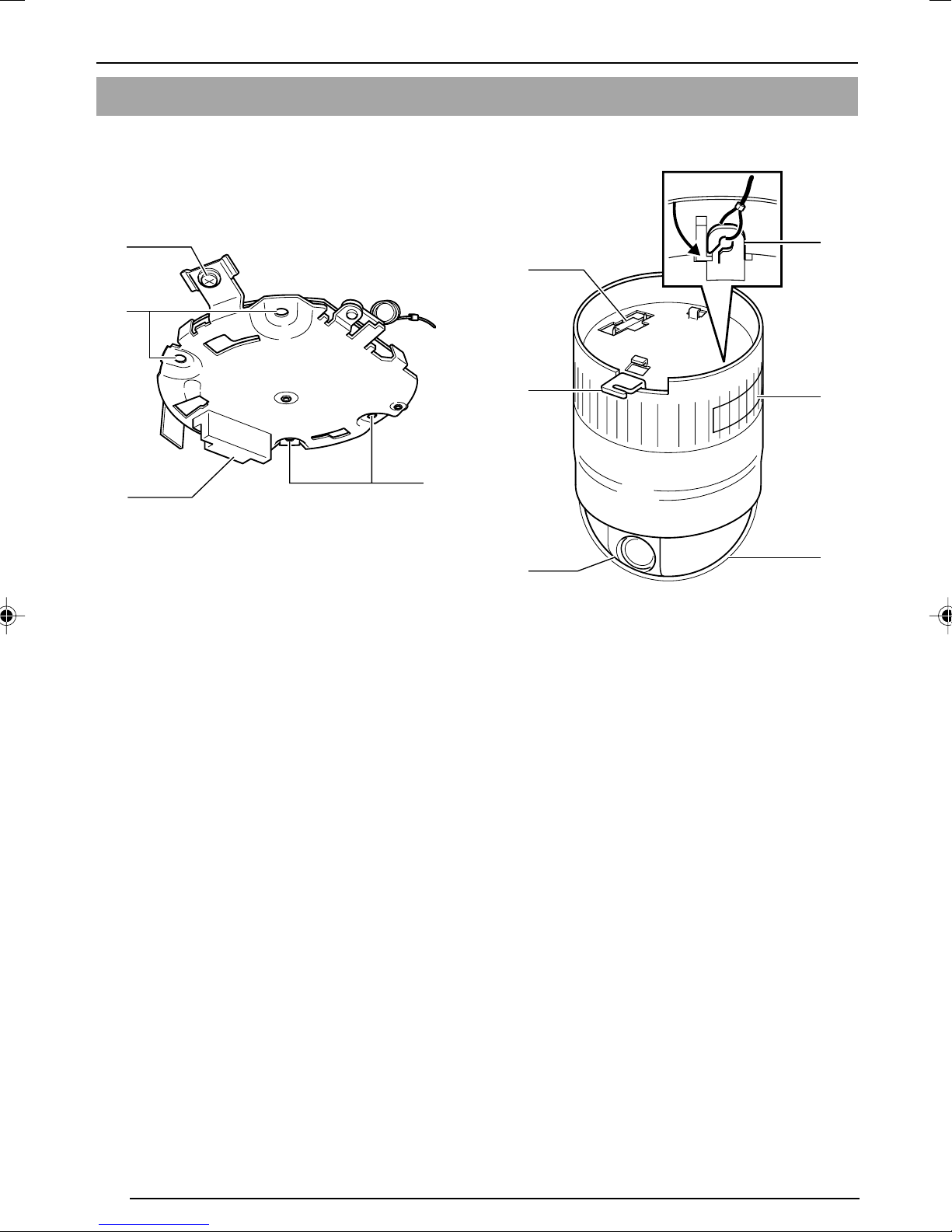
䡵Ceiling Mount (Terminal Side)
9
ENGLISH
8
1
2
3
Safety Wire
1
Hang this wire to the wire fastening hook & to
prevent the camera from falling down.
[VIDEO OUT] Coaxial Cable Terminal
2
Output terminal for composite video signals
(1 Vp-p and output impedance of 75Ø). Connect this to devices such as video monitors.
(☞ Page 17)
Output is restricted signals in the NTSC for-
mat only.
[POWER INPUT DC12V] DC12V Input Ter-
3
minal
Connect this to the Converter Unit that has
been supplied.
Safety Wire Mounting Hole
4
To prevent the camera from falling down, attach a wire from the ceiling slab or channel to
this hole.
[10BASE-T/100BASE-TX] 10BASE-T/
5
100BASE-TX Terminal
This is a 10BASE-T/100BASE-TX terminal. It
is used for connecting to the network via LAN
cables. (
Page 16)
☞
7
6
5
4
Locking Screw
6
Ensure to fasten the camera by fastening this
screw to the camera clamping bracket #.
[ALARM IN/OUT] Alarm Input/Output Ter-
7
minals
Te r minals for alarm input and output.
(
Page 15)
☞
Pin No.
1
2
3
4
5
Cover
8
This is a protection cover. Cut a slit in the rubber cap attached to the cover when wiring
cables. (
Cover Fastening Screw
9
This is used for fastening the cover 8 and ceil-
ing mount. To remove cover 8, do so by unfastening this screw.
Alarm Output
Alarm Input
Page 13)
☞
Signal Name
Alarm Output 1
Alarm Output 2
Alarm Input 1
Alarm Input 2
GND
E-9
Page 10
Introduction
Name and Function of Parts (continued)
䡵Ceiling Mount (Camera Terminal Side) 䡵Camera
6
0
!
Clamping Holes (x 4)
0
Use this hole to attach the camera to the ceiling or ceiling embedding bracket (WB-S625:
sold separately).
Camera Connection Terminal (Female)
!
Connect this to the connection terminal (male)
@ on the camera.
Connection Terminal (Male)
@
Connect this to the camera connection terminal (female) ! on the ceiling mount.
0
@
#
$
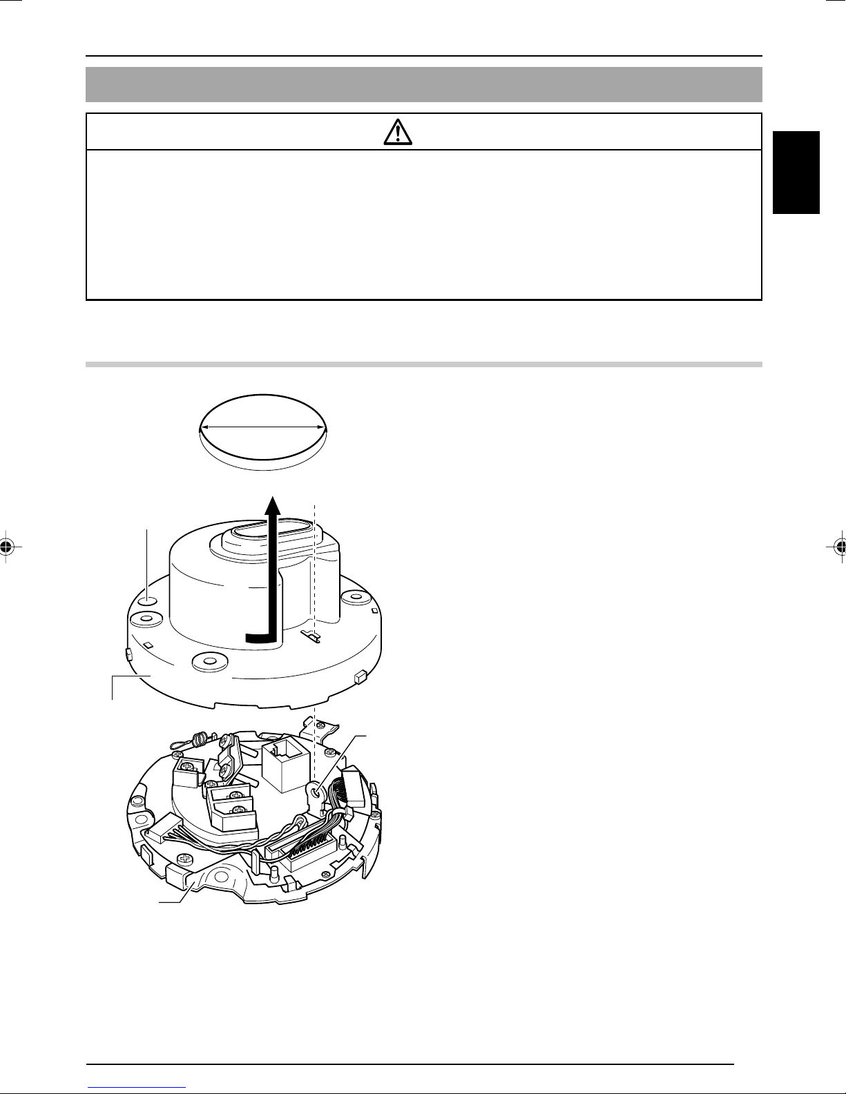
Dome Cover
%
The dome cover is fragile. Take care when
handling it.
CF (Compact Flash) Cover
^
Open the cover and insert the CF card.
(
Page 21)
☞
Fastening Hook for Safety Wire
&
Hook this to the safety wire 1 (to prevent cam-
era from falling down) on the ceiling mount.
&
^
%
Camera Clamping Bracket
#
Insert the locking screw 6 into this bracket
and tighten to fasten the camera and the ceiling mount.
Lens
$
The lens is not a replaceable item.
E-10
Page 11
Preparation
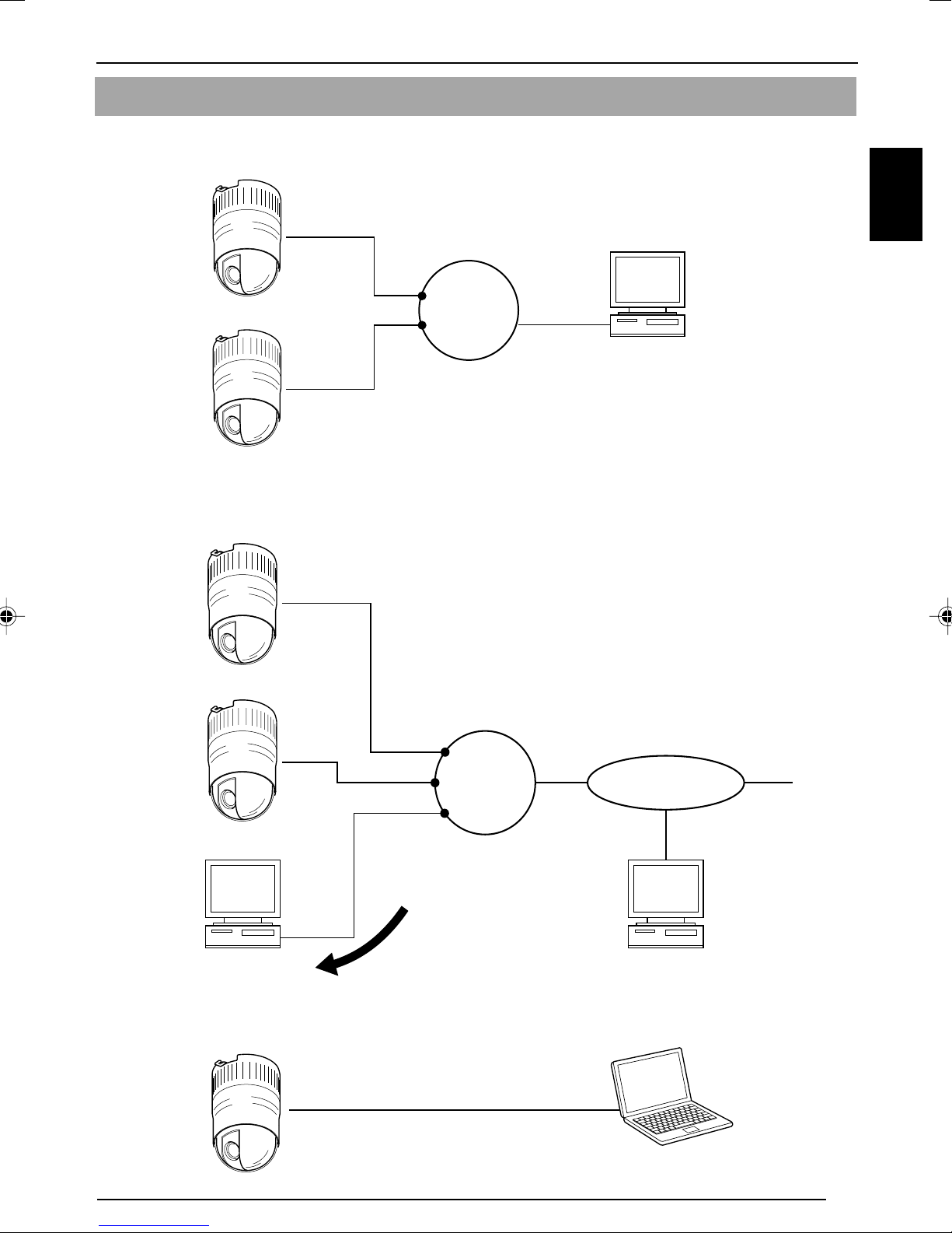
Connection Examples
LAN Connection
VN-C625
ENGLISH
VN-C625
Network Connection
VN-C625
VN-C625
LAN
PC
FTP Server
PC
Peer-to-Peer Connection
VN-C625
LAN INTERNET
Updated images are automatically
uploaded at a regular interval
Cross Cable
PC
PC
E-11
Page 12

Preparation
Preparation Procedure
Set the camera in the following procedure.
Step 1 Connection/Installation
Firstly, make a hole in the ceiling, followed by connecting the power cable, LAN
cable or alarm signal cable to the terminal of the ceiling mount of this camera.
Next, attach the camera to the ceiling. Do not forget to attach the safety wire.
Step 2 Network Settings
Install the software, set the network for this camera as well as using the "VNC625U Setup Tool", and register the connected camera with the "V.Networks
Controller".
In a system where more than 1 VN-C625 is used, turn on the power for a VN-C625
●
first, followed by setting the camera until "2-3 Setting IP Address for this Camera
Using the 'VN-C625U Setup Tool' " is completed. Upon doing so, turn on a second
camera and perform setting in the same way. Perform the same procedure for
subsequent cameras.
(☞Page 18)
Page 13
☞
Page 24
☞
Step 3 Setting Using the V.Networks Controller
Perform settings for Auto Pan, Auto Patrol, Auto Trace, Image Quality and Alarm
using the "V. Networks Controller" software that has been installed.
Step 4 Operating Using the V.Networks Controller
The "V. Networks Controller" can also be used to perform recording/playback
operations.
For details, refer to the PDF instruction manual inside the supplied CD-ROM.
☞
Step 5 Operating Using a Web Browser
Operation is possible via a web browser.
Page 31
☞
Page 34
☞
E-12
Page 13
Preparation (Step 1 Connection/Installation)
1-1 Connecting Cables
Cautions
● Attachment of a embedded cover in the ceiling (recess bracket) may be mandatory in certain
regions. If this is so, ensure that the embedded cover (recess bracket) is securely attached
before installing the camera.
● Ensure to attach the cover for the ceiling mount. Installation is not possible without attaching
the cover. In addition, the cover also prevents penetration of foreign objects into the ceiling
mount. Penetration of foreign objects may cause a malfunction or, in the worst scenario,
cause smoking or fire.
1. Connection Procedure
1.
Make a hole in the ceiling
75
Make use of the template supplied to open a
hole (75) for leading the connection cable
through the rear side of the ceiling.
ENGLISH
Cover Fastening
Screw
Cover
Ceiling
Mount
2.
Remove the cover
To remove the cover from the ceiling mount,
loosen the fastening screw on the cover,
followed by turning the cover in the anticlockwise direction.
Safety Wire Mounting Hole
E-13
Page 14

Preparation (Step 1 Connection/Installation)
1-1 Connecting Cables (Continued)
3.
Cap (Upper)
Lead the cable through the cover
Make a slit on the (rubber) cap that is attached
to the cover, followed by leading the cable
through. See diagram on the left on how to
make the slit.
4.
Connect the cable to this camera
Connect cables to the terminal on the ceiling
mount. Connection cables include alarm
signal cable, LAN cable, coaxial cable and that
for the Converter Unit.
Alarm signal cable (☞Page 15)
1
Connect this cable to devices with alarm
input/output terminals.
1
2
3
4
LAN cable (☞Page 16)
2
Connect this cable to a hub or PC.
Coaxial cable (☞Page 17)
3
Connect this cable to NTSC monitors.
Converter Unit (☞Page 18)
4
Connect this to a DC12V power supply.
5.
Attach the cover
Attach the cover to the ceiling mount by
following procedure of Step 2 in the reverse
order.
Attach the cover upon aligning the hole with
1
the safety wire mounting hole on the ceiling
mount, followed by turning it in the
clockwise direction.
Fasten the cover fastening screw.
2
E-14
Page 15

2. Connection to Alarm Input/Output Terminal
Connect the alarm input/output terminals to
1
Flathead
Screwdriver
1
2
4 mm
Alarm Signal
Cable
4
3
Flathead
Screwdriver
external devices such as sensors and buzzers.
Loosen the screws on both edges of the
1
terminal block using a flathead screwdriver,
followed by dismantling it as shown in the left
diagram.
Strip the coating of the alarm signal cable by
2
about 4mm before inserting it into the terminal.
Tu rn the screw on the side to fasten the alarm
3
signal cable.
Upon fastening the alarm signal cable, re-
4
install the terminal block that has been
dismantled in Step 1.
Note
Cable Specifications
50 m or shorter in length
UL1007, UL1015 or equivalent
AWG#22 to AWG#18 or equivalent
ENGLISH
䡵 Alarm Input Terminal
VN-C625
DC12V
R
(Alarm Input
Equivalent Circuit)
Te rminal
1 or 2
12V
Grounding
Te r minal
OUT
1.2mA
GND
OUT
Sensor
Connection
Example (1)
VCC
R
Sensor
Connection
Example (2)
Relay, switch,
etc.
Caution
Due to external noise, the cable may not
function properly even when the cable length
is less than 50 m. In this case, use a shielded
cable or take measures such as keeping the
cable away from the noise source.
Connect this terminal to an infrared, door or
metallic sensor, or to a manual switch.
Input Requirements
● No-voltage relay or NPN open collector input
● The polarity of input detection can be selected
via software
● Make/Break/Toggle (at least 250 ms)
● Circuit current at low-level: 1.2 mA
● Voltage applied at high level: 12 V
GND
E-15
Page 16

Preparation (Step 1 Connection/Installation)
1-1 Connecting Cables (Continued)
䡵 Alarm Output Terminal
Connect this terminal to alarm devices such
as an annunciator, indicator, lamp or buzzer.
Output Requirements
• Equivalent to NPN open collector output (Set
output logic using the controller)
• Allowed applied voltage: DC12V and below
• Allowed input current: 50 mA
• Momentary output: 1 to 5000ms (Set duration
using the controller)
VN-C625
OUT
Te rminal
Grounding
Te r minal
IN
GND
Alarm Device
Connection
Example
DC 12 V
R
(Alarm Output
Equivalent Circuit)
3. Connection of LAN Cables
Caution
Connect the grounding terminal of VN-C625
to the GND terminal of the alarm device.
Use the LAN cable to connect this camera
to a hub or PC
When connecting to a hub
make use of a straight cable.
When connecting to a PC
make use of a cross cable.
Note
When using 100 BASE-TX, ensure to use a Category 5 (or higher) cable.
E-16
Caution
The use of a cross cable may not be
supported by certain LAN boards on some
rare occasions. As such, please check your
LAN board specifications before connection.
Page 17
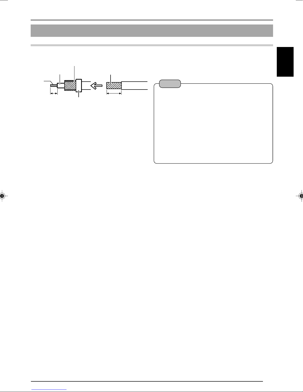
4. Connection of Coaxial Cables
Polyethylene
Mesh
Wires
*
Core Wire
Connecting a 5C-2V or 3C-2V coaxial cable
Strip the coaxial cable according to the
diagram on the left. (Unit: mm)
Notes
ENGLISH
7
Insulation Tape
17
• 7C-2V coaxial cables cannot be connected
directly to the terminal block. In this case,
make use of the 5C-2V cable as a junction
cable by connecting it to this camera.
Fold back the mesh wires and secure
*
using an insulation tape to prevent them
from becoming loose and causing a
short circuit.
• Video output signal of the VIDEO OUT
terminal is restricted to NTSC signals.
E-17
Page 18

Preparation (Step 1 Connection/Installation)
1-1 Connecting Cables (Continued)
5. Connection of Conveter Unit
Connect the camera to AC 24 V.
1.
Disconnect the connector from the supplied Converter Unit.
It can be disconnected by pressing both ends
as shown in the left figure.
1.
Press
2.
Press
Power cable
5mm
Press
Connector
3.
2.
Mount the power cable to the connector.
Strip the cover of the power cable (about 5
mm), while pressing down the arrow portion
to AC 24V
4.
When a 2-conductor VVF (Vinyl-insulated vinyl-sheath cable) is used, the maximum connection length
is as shown below. (These are merely the standard reference values.)
Maximum cable length 80 m 210 m 330 m 560 m
Wire diameter (mm) 1.0 or more 1.6 or more 2.0 or more 2.6 or more
using a flat screwdriver, insert it into the connector.
3.
Mount the connector.
4.
Connect the supplied Converter Unit to
the DC 12 V input terminal on the terminal
stand.
Caution
• Connect with the appropriate power-supply voltage. The rated voltage for VN-C625 (Converter
Unit) is AC 24 V, 50 Hz/60 Hz and shall be Class 2.
If a voltage exceeding the rating is supplied, malfunction, or in the worst case, fuming or fire,
may be caused.
• Installation shall be performed by qualified personnel according to regulations of individual
regions.
Notes
Connecting multiple VN-C625 Cameras
In a system where more than 1 VN-C625 is used, turn on the power for a VN-C625 first, followed
by setting the camera until "2-3 Setting IP Address for this Camera Using the 'VN-C625U Setup
Tool' " is completed. Upon doing so, turn on a second camera and perform setting in the same
way. Perform the same procedure for subsequent cameras.
• Default IP address setting for all VN-C625 cameras is 198.168.0.2. When the power for multiple
cameras are turned on at one time under a single LAN environment, therefore, proper access
may not be established due to IP address redundancy. Do not turn on the power of more than
1 camera at the same time.
• When IP address redundancy occurs, ensure that only one VN-C625 exists under a single
LAN environment, and wait for some time (at least 10 minutes). In some cases, the power for
all network devices under the same LAN environment may have to be turned off and on again
to enable access to VN-C625.
E-18
Page 19

1-2 Attachment of Ceiling Mount
Caution
Ceiling
Embedded Cover in Ceiling (recess bracket)
Attach to Ceiling Slab or Channel
• Attachment of a embedded cover in the ceiling
(recess bracket) may be mandatory in certain
regions. If this is so, ensure that the embedded
cover (recess bracket) is securely attached
before installing the camera.
Please refer to the instruction manual for the cover
•
in use for details on installation of the embedded
cover (recess bracket).
•
For more detail, please contact the JVC.
1.
Attach safety wire to prevent camera
from falling down
Connect the ceiling slab or channel to the
ceiling mount using the wire to prevent the
camera from falling down. Make use of the
safety wire mounting hole to connect the
ceiling mount and the wire.
(See diagram on the left)
ENGLISH
Ceiling Mount
Safety Wire
Safety Wire Mounting
Hole
Cautions
Choose a wire and ceiling structure with an
appropriate strength and length that may
prevent danger in case the camera falls down.
Notes
• Connect the wire so that it can be insulated
from the ceiling structure.
If the ceiling structure is made of a metallic
material, improper insulation with the
camera may cause noise interference in
the images.
• Safety wires are not provided. Please
purchase commercially available wires on
a separate basis.
E-19
Page 20

Preparation (Step 1 Connection/Installation)
1-2 Attachment of Ceiling Mount (Continued)
2.
Fasten the ceiling mount to the ceiling
Align the “™FRONT” mark on the ceiling mount
in the direction that the camera is facing.
Fasten the ceiling mount using the 4 screws
while taking care not to catch the connection
cables. Use M4-sized (No 8) screws or bolts.
For woodscrews, make use of those with a
diameter of 4.1 mm.
Notes
• Be sure to use 4 screws and attach them
firmly.
• The seals attached to the ceiling-mount
screw holes of the ceiling mount act as an
FRONT
FRONT
Mark
Orientation
of Camera
insulator between the ceiling mount and the
ceiling structure. If the ceiling structure is
made of a metallic material, improper
insulation with the camera may cause noise
interference in the images. To prevent this
from occurring, ensure proper insulation
during installation.
Screws
E-20
Page 21

1-3 Inserting the CF card
1.
Check to ensure that the power of the
camera is not turned on
CF Cover
Surface
2.
4.
3.
Eject Button
2.
Remove the CF (compact flash) cover
3.
Insert CF card in the direction as
indicated in the diagram
• Press once if the eject button is protruding
• Insert the CF card all the way until you hear
a "click" sound
4.
Attach the CF cover dismantled in Step
* When removing the card, ensure that the power
of the camera is turned off before pressing the
eject button.
<List of Tested CF Cards>
• San Disk (Industrial)
128MB (SDCFBI-128-201-80)
256MB (SDCFBI-256-201-80)
512MB (SDCFBI-512-201-80)
1024MB (SDCFBI-1024-201-80)
•Hagiwara Sys-Com Z-pro Series
128MB (HPC-CF128ZP)
256MB (HPC-CF256ZP)
512MB (HPC-CF512ZP)
1GB (HPC-CF1GZP)
ENGLISH
2
E-21
Page 22

Preparation (Step 1 Connection/Installation)
1-4 Installing the Camera
1.
Attach the safety wire to prevent the
camera from falling down
Safety Wire
Fastening Hook for Safety Wire
Ceiling Mount
Locking Screw
As shown in the diagram, pull out the safety
wire from the ceiling mount and hang it to the
safety wire fastening hook on the camera.
Be sure to connect the safety wire to prevent
the camera from falling down.
• Do not connect cameras other than VNC625 to the ceiling mount. Doing so may
cause the camera to malfunction.
• Be sure to connect the safety wire.
Otherwise, the camera may fall to the
ground.
• Do not leave the camera hung with the
safety wire. The spring characteristic of the
safety wire will lose. It might not be able to
mount properly when inserting the camera
unit to the ceiling mount if the wire is
caught.
Cautions
Camera
Camera Clamping
Bracket
&Mark
2.
Check that the locking screw is loosened
The camera cannot be properly installed if the
locking screw of the ceiling mount is not
loosened.
3.
Fit the camera to the ceiling mount
Align the "^" mark of the camera unit with
"&" mark of the ceiling mount, and fit the
camera to the ceiling mount upon checking
the positions of the camera clamping bracket
as well as the locking screw on the ceiling
mount.
E-22
Page 23

Camera Clamping Bracket
Tu rn camera in
clockwise
direction
4.
Turn the camera
Make sure that the camera is horizontal,
followed by fitting the camera to the ceiling
mount and turning it in the clockwise direction
until it stops. Upon doing so, check that the
the camera clamping bracket is aligned with
the position of the locking screw of the ceiling
mount.
5.
Fasten the locking screw
Fasten the locking screw using a flathead
screwdriver.
ENGLISH
Fasten the locking screw
Locking
Screw
Cautions
If the locking screw is not securely fastened,
the camera may vibrate or fall down.
Be sure to fasten the locking screw firmly.
* To dismantle the camera, perform procedure
from steps
1
to 5 in the reverse order.
E-23
Page 24
Settings (Step 2 Network Settings)
2-1 Installing the Software
To operate this camera, you will have to install the necessary software according to
the following procedure from the CD-ROM supplied.
Installing the V.Networks Controller
1. Execute "Setup.exe" in the [JVC] folder.
2. Follow instructions on the screen to install the software.
3. If installation is successful, the † "V.Networks Controller" icon will be displayed in the [Start] †
[Programs]
Installing the VN-C625U Setup Tool
1. Execute "Setup.exe". This is located inside the [Setup] folder of the [JVC] folder.
2. Follow instructions on the screen to install the software.
3. If installation is successful, the † "VN-C625U Setup Tool" icon will be displayed in the [Start] †
[Programs]
[V. NETWORKS] folder.
[V. NETWORKS] folder.
~~~~~~~~~~~~~~~~~~~
E-24
Page 25

2-2 Setting PC's IP Address [Windows XP]
Upon installing the camera, set the IP address of the PC that is used to operate this
camera.
For Windows XP, set according to the following procedure.
(For Windows 2000, ☞ Page 27)
Note
Under a DHCP environment and when the IP address assigned to V. Networks is already known,
it will not be necessary to perform 2-2 "Setting PC's IP Address" as the PC's IP address is
automatically acquired from the DHCP server.
1.
Click .
• Right-click on [My Network] and select [Properties].
2.
Select the network for which the PC that operates this camera is connected to.
• Right-click to select [Properties].
ENGLISH
Ensure that it is selected.
Note
Select "Install ..." if [Client for Microsoft
Networks] or [Internet Protocol (TCP/
IP)] is not displayed.
E-25
Page 26
Settings (Step 2 Network Settings)
2-2 Setting PC's IP Address [Windows XP] (Continued)
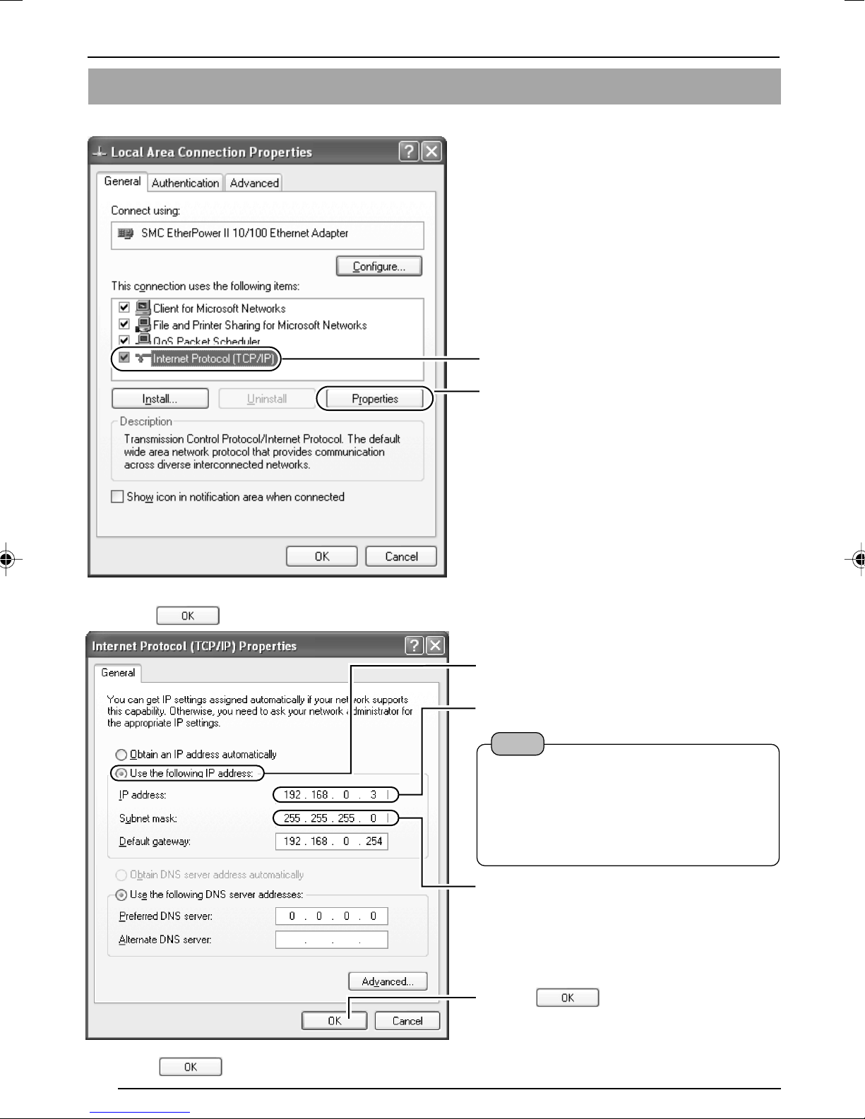
3.
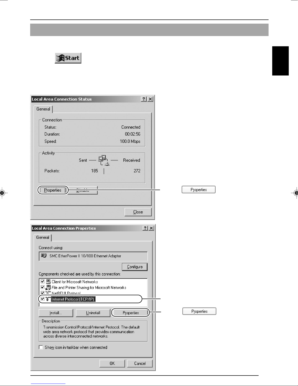
Select [Internet Protocol (TCP/IP)] and click [Properties].
Select [Internet Protocol (TCP/IP)].
1
Click [Properties].
2
4.
Select [Use the following IP address], set the [IP address] and [Subnet mask] and
click
.
Select [Use the following IP address].
1
Set [IP address] to 192.168.0.3.
2
Note
• Make sure to note down the original
IP address before changing.
• Do not use the same IP address
elsewhere within the same network
environment.
Set Subnet mask to an appropriate value.
3
Ask the network administrator if
necessary.
Click .
4
5.
Click on the [Local Area Connection Properties] screen.
E-26
Page 27
2-2 Setting PC's IP Address [Windows 2000]
Upon installing the camera, set the IP address of the PC that is used to operate this camera.
For Windows 2000, set according to the following procedure.
1.
Click .
• Select [Settings] and click [Properties].
2.
Double-click [Network and Dial-up Connection].
3.
Double-click [Local Area Connection].
ENGLISH
Click .
1
Select [Internet Protocol (TCP/IP)].
2
Click .
3
E-27
Page 28

Settings (Step 2 Network Settings)
2-2 Setting PC's IP Address [Windows 2000] (Continued)
Select [Use the following IP address].
4
Set [IP address] to 192.168.0.3.
5
Set Subnet mask to an appropriate value.
6
Ask the network administrator if
necessary.
4.Click .
E-28
Page 29

2-3 Setting IP Address for this Camera Using the "VN-C625U Setup Tool"
Set the IP address for VN-C625 using the "VN-C625U Setup Tool" that has been installed.
(This "VN-C625U Setup Tool" only allows connection of VN-C625.)
Caution
• Upon turning on the power of this camera, it may take about 60 seconds before it can be
connected to the PC.
• At the factory, DHCP is enabled for VN-C625.
• Using DHCP
JVC does not recommend operating VN-C625 with the DHCP function enabled because a
different IP address may be assigned upon the renewal of the leasing contract. The DHCP
function of VN-C625 is included with the aim to simplify installation/setting procedures.
Note
•To connect to a VN-C625 for which DHCP has been enabled, the DHCP server must exist in an
environment where the assigned IP address and MAC address are clearly defined. If the DHCP
server is not found, it will automatically start up using the static IP address after 60 seconds.
ENGLISH
1.
Select [Start] † [Programs] † [V.NETWORKS] † [VN-C625U Setup Tool] to start
up the "VN-C625U Setup Tool".
Enter the IP address of the camera to be
1
connected in [Connection IP address].
Default IP address is
Click .
2
192.168.0.2.
Note
To view the IP address of the connected camera, click "Search".
The [V.Networks Search] screen is
displayed.
Click
a [V.Networks IP Address List] will
appear.
to start search and
• [TimeOut] is for setting the time for searching (1 to 30 seconds). If no IP address is displayed
upon searching, change the value to a longer time and search again.
• If the [V.Networks] on the LAN has a different subnet from that of the PC, connection may not
be possible even if the IP address of the camera is found via search. Change the IP address
of the PC to an appropriate value and connect the camera.
E-29
Page 30

Settings (Step 2 Network Settings)
2-3 Setting IP Address for this Camera Using the "VN-C625U Setup Tool" (Continued)
2.
Check settings.
Select whether to use DHCP.
1
Note
The IP address of the DHCP server
and other information can be checked
when [DHCP] is selected.
Change the IP address to the one assigned
2
to or approved by the administrator.
Set Subnet mask to an appropriate value.
3
Ask the network administrator if necessary.
3.
Click .
4.
Start up the "V.Networks Controller".
(☞ Page 31)
Click .
4
[V.Networks ID] works as an identification
code set to VN-C625. Only alphanumeric
characters can be used.
This ID does not directly affect operation
by the user.
Normally, the ID is set as CAM00001,
CAM00002, etc.
(0 to 8 characters)
Click .
Note
Upon clicking OK, VN-C625 will be
automatically reset and the set values
will be enabled.
Note
In a system where more than 1 VN-C625 is used, turn on the power for a VN-C625 first, followed
by setting the camera until "2-3 Setting IP Address for this Camera Using the 'VN-C625U Setup
Tool' " is completed. Upon doing so, turn on a second camera and perform setting in the same
way. Perform the same procedure for subsequent cameras.
E-30
Page 31

2
Settings (Step 3 Setting Using the V.Networks Controller)
3-1 Starting Up V.Networks Controller
The installed "V.Networks Controller" can be used to monitor camera images.
In addition, recording/playback operations and setting of frame rate for camera
images are also possible.
1.
Select [Start] † [Programs] † [V. NETWORKS] † [V.Networks Controller] to
start up the "V.Networks Controller".
Select the camera to connect to from the
1
pull-down menu for the camera.
ENGLISH
Live images from the camera wil be
2
displayed.
Notes
● Enter the correct password if a password has been set.
● This controller can be connected to VN-C1, VN-C2, VN-C3, VN-C30 (JPEG only), VN-A1,
VN-C10 (JPEG and MPEG), VN-C655 as well VN-C625.
E-31
Page 32

Settings (Step 3 Setting Using the V.Networks Controller)
3-2 Features that Allow Setting Using the V.Networks Controller
The V.Networks Controller can be used to perform settings for image size and alarm.
1 2 3
File
1
New : Creates a new file if the camera
is connected for the first time.
Delete : Deletes a file.
Motion Detection Standby
: Select the camera for which
the Motion Detection Standby
function is to be enabled.
Exit : Exits the controller.
Notes
● The following setting are disabled during
Auto Pan:
• Auto Pan Setting
• Auto Patrol Setting
• Auto Trace Setting
• Preset Position Setting
• Pan Control
View
2
Image Size : Sets the image display size.
JPEG : 640 x 480
320 x 240
Upside Down: Displays the image inversely.
Control (C)
3
Auto Pan : Select this item and click to
start the Auto Pan operation.
Auto Patrol (Mode1 to Mode 3)
: Select a mode for this item and
click to start the Auto Patrol
operation for the selected
mode.
Auto Trace : Select this item and click to
start the Auto Trace operation.
Auto Pan Stop
: Stops the Auto Pan operation.
Auto Patrol Stop
Stops the Auto Patrol operation.
:
Auto Trace Stop
Stops the Auto Trace operation.
:
● The following setting are disabled during
Auto Patrol:
• Auto Pan Setting
• Auto Patrol Setting
• Auto Trace Setting
• Preset Position Setting
• Pan/Tilt Control
• Zoom Control
● The following setting are disabled during
Auto Trace:
• Auto Pan Setting
• Auto Patrol Setting
• Auto Trace Setting
• Preset Position Setting
• Pan/Tilt Control
• Zoom Control
• Focus Control
E-32
Page 33

54
ENGLISH
Setting
4
Quality :
Frame rate : For setting the number of
Position Memory:
Alarm Reg : Alarm operation will be
Alarm Setting :For setting alarm actions
Pan/Tilt Setting : For setting the Pan/Tilt
Auto Pan Setting : For setting the Auto Pan
Auto Patrol Setting
Auto Trace Setting
Time Stamp : For setting the date and
Property :For changing information
For setting the compression
rate and image quality.
camera images to send per
second.
For setting preset positions.
enabled if this item is
checked.
for each alarm.
operation (speed, Auto
Flip).
operation.
:For setting Auto Patrol
operation.
:For setting the Auto Trace
operation.
time display of a stored file.
of cameras that are not
currently connected.
Help
5
About :For checking the version of
the V.Networks Controller.
*As for the details of other settings and “Step 4 Operation Using the V.NETWORKS Controller”,
read “Instruction Manual” (PDF) in the supplied CD-ROM.
E-33
Page 34

Operations (Step 5 Operating Using a Web Browser)
In addition to the controller software supplied, web browsers can also be used to
view still/motion images as well as to perform various settings.
5-1 Operating Environment
The following environment will be required to view/operate VN-C625 using a web browser.
The PC in use shall also meet requirements on the operation environment stated in this
manual (
PCs installed with the following web browsers
● Internet Explorer 4.x, 5.x or 6.x.
● For CPU performance, required memory space and other values, please refer to the
recommended values by the respective web browser in use.
In order to enable smooth display of motion images on a large screen, it will be necessary to
ensure adequate allowance as compared with the recommended values by web browsers. In
addition, images of the installed camera cannot be properly displayed using 256 color modes.
Page 9).
☞
Caution
Operation using the web browser requires an environment that enables proper running of
Java. Please refer to our web site for details.
http://www.jvc-victor.co.jp/english/pro/vnetworks/index-e.html
LAN Environment
● VN-C625 functions as a web server that makes use of a HTTP protocol.
Access linking by host name will be possible as long as the environment allows use of a DNS
(Domain Name System).
● It is possible to establish a 1-to-1 connection between the PC and VN-C625 using a cross cable.
(Although rare, the use of cross cables may not be possible with some LAN boards. Be sure to
check before using.)
Notes
Web Page Images
Web page screens in this manual are web page data inside VN-C625 (including images shot
using the installed camera) which are displayed using the web page browsing/display function
of the browser.
As such, the format of web pages and fonts displayed may vary according to the type of browser
and settings.
In the event that items on the screen are not fully displayed, hence causing problems during
use, display all items such as by resizing the window.
Description in this manual is based on the web page browsing/display screen of Internet Explorer.
Password
Upon changing a password, the password confirmation screen may appear, which requires you
to enter the new password twice. When this screen appears, enter the same password twice.
E-34
Page 35

5-2 Access Authorization Level
The configuration of URLs (web pages) in VN-C625 is illustrated as follows.
Access Authorization Level
<<
User
>>
Top page (index-e.html)
Still image page (still-e.html)
Operator
>> <<
Administrator
>><<
ENGLISH
Live image page
Still image URL (still.jpg)
Serverpush moving image URL
Java moving image URL
(mjpeg.class)
Front Page: http://
(java-e.html)
(push.jpg)
/index-e.html ("
******
Control (pantilt-e.html)
" represents the URL of VN-C625)
******
Settings ( java config-e. html )
Setting page
PAN/TILT settings(configpantilt-e.html)
Position Memory(position-e.html)
Image settings(configimage-e. html )
View settings(view config-e. html )
Alarm settings(alarm-e. html )
FTP settings(ftp-e. html )
Auto Pan settings(autopan-e.html)
Auto Patrol settings(autopatrol-e.html)
Auto Trace settings(auto trace-e.html)
Black&White settings(bwconfig-e.html)
Schedule Setting(bwschedule-e. html)
PrivateMask Setting(privatemask-e. html)
Limit Setting(pantiltlimit-e. html)
Auto Return Setting(selfreturn-e. html)
Other settings(config-e. html )
This page provides links to the various web pages of VN-C625.
Authentication of Access Authorization
When there are authenticated passwords, a message requesting entry of user name and password
(acess authorization authentication) will appear.
Notes
It is recommended that you register a URL (Uniform Resource Locator).
To speed up display of VN-C625 web pages using your web browser, register the URL information
during the access test using the set IP addres or DNS host name.
This is represented by [Favorites] in Internet Explorer. To register, use the [Add to Favorites]
item in the operation menu of the web browser when a VN-C625 web page is displayed.
User name is not used.
1
Enter a password among the 3 different levels that
2
have been set.
Click .
3
E-35
Page 36

Operations (Step 5 Operating Using a Web Browser)
5-3 Starting Up the Web Browser
Specify the default web page address of VN-C625 as the page to view using the web
browser. (Upon entering the factory setting of the IP address, the web browser will
display the front page of VN-C625.)
Note
You may not be able to specify the IP address directly if a proxy server is set for accessing the
Internet. In this case, change the proxy settings to enable direct specification.
1.
Start up the web browser.
"http://192.168.0.2/index-e.html"
Notes
The terms "Top Page" and "Home Page" are defined as follows in this manual.
Top Page : Refers to /index-e.html
Home Page :• Refers to the specified html page when the default page feature is enabled.
• /index-e.html will be used when the default page is disabled.
2.
The Top page will be displayed.
Still Image of VN-C625
Camera image at the point when browsing starts is
displayed.
Link buttons to various web pages.
(Click once to jump to these pages.)
* For details, refer to the PDF instruction manual inside the supplied CD-ROM.
E-36
Page 37

Others
Specifications
䡵 Camera
Image pickup
device :1/4-inch type, interline
transfer CCD,
768 (H) x 494 (V)
Sync system : Internal
Scanning
frequencies : 15.734 kHz (Horizontal),
59.95 Hz (Vertical)
White Balance : TTL auto tracking/Manual
Electronic Shutter
Backlight
compensation :Possible, 4 photometry
Color level
adjustment :Possible
Contour correction
[Video Output]
Color System : NTSC
S/N : 50 dB (Standard)
Minimum object
illumination : (Color mode):
:1/60, 1/100, 1/250, 1/500, 1/
1000, 1/2000, 1/4000, 1/
10000 sec.
areas selectable
: Both horizontal and vertical
(level adjustable)
(AGC: Off, Enhancer: -5)
3.6 lx (50% output, AGC 20
dB, Wide-end)
1.8 lx (25% output, AGC 20
dB, Wide-end)
(Black & White mode):
0.15 lx (50% output,
AGC 20 dB, Wide-end)
0.075 lx (25% output,
AGC 20 dB, Wide-end)
䡵 Rotating Table (Pan/Tilt Mechanism)
Panning range : 360˚ endless revolution
Panning speed : 1.5˚/s to 180˚/s
Tilting range : 0˚ to 90˚ (Horizontal to
straight downwards)
Tilting speed : 1˚/s to 120˚/s
䡵 LAN Standard
Communication
protocol : TCP, UDP, FTP, ICMP, ARP,
DHCP, NTP, HTTP
䡵 General
Power supply : DC 12 V, 2 A
No. of preset
positions : 100
Ambient
temperature : 0˚C to 40˚C
Humidity : 20% to 85% RH (without
condensation)
Mass : Approx. 1.2 k˝ (Excluding AC
adaptor)
Accessories : Read Me First .................. 1
CD-ROM .......................... 1
Warranty Card ................. 1
Service Information Card 1
Ceiling Mount .................. 1
Converter Unit ................. 1
Template .......................... 1
ENGLISH
䡵 Lens
Zoom ratio :x 12 (Approx.)
Focal distance : 3.8 mm to 45.6 mm
Maximum aperture:F1.6 (Wide) to F2.7 (Tele)
E-37
Page 38

Others
Specifications (Continued)
䡵 External Dimensions [Unit: mm]
127
190 36
SR55
φ120
46
䡵 Ceiling Mount Hole [Unit: mm]
Screw Positions
83.5
71
70
Mounting Hole φ75
46
Screw Positions
* Specifications and appearance of this unit and related products are subject to change for
product improvement without prior notice.
E-38
83.5
Page 39

DOME TYPE NETWORK CAMERA
BITTE ZUERST LESEN
VN-C625
DEUTSCH
Page 40

Im Sinne einer stetigen Produktverbesserung
konnen Angaben in dieser Anleitung ohne
vorherige Ankundigung geandert werden.
ACHTUNG :
ZUR VERMEIDUNG VON FEUERUND STROMSCHLAGGEFAHR
DARF DIESES GERÄT NICHT
NÄSSE ODER FEUCHTIGKEIT
AUSGESETZT WERDEN.
Installations- und Montagearbeiten sind von
qualifiziertem Fachpersonal entsprechend
den geltenden Richtlinien durchzuführen.
Installations- und Montagearbeiten sind in
Übereinstimmung mit dem National Electrical
Code, ANSI/NFPA 70, durchzuführen.
Dieses Produkte sollte nur mit einem Listed
Class 2-Netzteil betrieben werden.
Ggf. in diesem Handbuch aufgeführte
Alarmeingänge und -ausgänge wurden von
den UL nicht auf ihre Tauglichkeit als
Einbruchsalarmsysteme geprüft.
DEUTSCH
D-3
Page 41

Einleitung
Wir wollen Ihnen für den Erwerb dieses Produkts danken.
(Diese Anleitung bezieht sich auf das Gerät VN-C625U.)
Lesen Sie diese Anleitung bitte vor Inbetriebnahme aufmerksam durch, um Ihr neues
Gerät optimal nutzen zu können.
Inhaltsverzeichnis
Inhaltsverzeichnis................................................................................... 4
Einleitung
Merkmale ............................................................................................... 5
Betriebshinweise .................................................................................... 5
Lieferumfang .......................................................................................... 8
Betriebsbedingungen ............................................................................. 8
Letzte Aktualisierungen .......................................................................... 8
Bedienelemente und Funktionen ........................................................... 9
Vorbereitung
Einstellungen
Anschlussbeispiele .............................................................................. 11
Vorbereitungen ..................................................................................... 12
Schritt 1: Anschluss und Installation
1-1 Anschlussverbindungen ............................................................. 13
1. Anschlussvorgang ....................................................................13
2. Verbindung mit Alarm-E/A-Anschlüssen .................................. 15
3. Anschluss von LAN-Kabeln ...................................................... 16
4. Anschluss von Koaxialkabeln ................................................... 17
5. Anschluss des Netzgeräts ........................................................ 18
1-2 Deckenmontage ......................................................................... 19
1-3 Einsetzen der CF-Karte ............................................................. 21
1-4 Installieren der Kamera .............................................................. 22
Schritt 2: Netzwerkeinstellungen
2-1 Installieren der Software ............................................................ 24
2-2 Einstellen der IP-Adresse des PCs [Windows XP] .................... 25
Einstellen der IP-Adresse des PCs [Windows 2000] ................. 27
2-3
Einstellen der IP-Adresse dieser Kamera mit dem „VN-C625U Setup Tool
Schritt 3: Konfigurieren von V.Networks Controller
“......29
3-1 Inbetriebnahme von V.Networks Controller ................................ 31
3-2
Schritt 4: Betrieb mit V.Networks Controller
Betrieb
Sonstiges
D-4
*Lesen Sie für Schritt 4 das PDF-Dokument „Instruction Manual“ auf der
beiliegenden CD-ROM.
Schritt 5: Betrieb mit einem Webbrowser
5-1 Betriebsbedingungen ................................................................. 34
5-2 Zugangsautorisierungsebene .................................................... 35
5-3 Starten des Webbrowsers .......................................................... 36
Technische Daten ................................................................................. 37
Mithilfe von V.Networks Controller vorzunehmende Einstellungen .........
32
Page 42

Merkmale
Tisch mit hoher Rotationsgeschwindigkeit
Der schnell drehende Tisch mit einer horizontalen
Schwenkgeschwindigkeit von 180 ˚/s und einer
vertikalen Neigungsgeschwindigkeit von 120 ˚/s
ermöglicht das extrem schnelle Anfahren einer
Presetposition.
Optischer Zoom
Dank des Objektivs mit optischem 12fach-Zoom
ist eine genauere Beobachtung möglich.
Tag- und Nachtbeobachtung
Wenn das Umgebungslicht schwach ist, schaltet
die Kamera bei Bedarf automatisch auf den
Hochempfindlichkeitsmodus (schwarzweiß) um,
indem der IR-Filter ein- oder ausgeschaltet wird.
Es werden auch Infrarotlichtquellen mit 850 bis
880 nm Wellenlänge unterstützt.
Hochempfindliches CCD und Objektiv mit
hellem Zoom
Die Verwendung eines hochempfindlichen CCD
und eines Bright-Zoom-Objektivs mit maximalem
Blendenverhältnis von F1,6 (am Weitwinkelende)
ermöglicht einen hochempfindlichen Farbmodus
von 3,6 lx (AGC: 20 dB, 50 %).
Bildrate
Unterstützt eine maximale Rate von 30 Bildern
pro Sekunde bei einer Auflösung von 640 x 480
Bildpunkten im JPEG-Format.
Multicastingunterstützung
Die Multicastingunterstützung ermöglicht den
gleichzeitigen Versand von Bilddaten an mehrere
PCs im Netzwerk ohne Verringerung der Bildrate.
Integrierter CF-Steckplatz
Mit Alarmschnittstelle. Ermöglicht das Speichern
einer Aufzeichnungsdatei auf einer CF-Karte
(Compact Flash). (Die CF-Karte ist nicht im
Lieferumfang enthalten.)
Maskierung von Privatbereichen
Diese Funktion ermöglicht die Konfiguration einer
Maske, mit der ein beliebiger Teil des
Erfassungsbereichs verborgen werden kann.
Bewegungserkennung
Ermöglicht die Ausgabe von Alarmsignalen bei
Erkennung von Bewegungen innerhalb eines
bestimmten Bereichs.
Integrierter Webserver
Ermöglicht eine Anzeige mit dem Internet Explorer.
DEUTSCH
Betriebshinweise
Um Energie zu sparen, schalten Sie das System
ab, wenn Sie es nicht verwenden.
Diese Kamera ist für den Einsatz im Innenbereich
vorgesehen. Ein Einsatz in Außenbereichen ist
nicht möglich.
Diese Kamera ist für die Deckenmontage
vorgesehen. Eine Montage am Boden oder eine
Schrägmontage kann zu Fehlfunktionen führen und
die Lebensdauer des Produkts verkürzen.
Installieren Sie die Kamera nicht an den
folgenden Orten:
•Orte, wo sie Regen oder Wasser ausgesetzt ist
•Orte, an denen Dampf oder Ruß auftreten (z. B.
Küchen)
•
Orte, deren Umgebungstemperatur nicht den
Spezifikationen entspricht (0
•Orte, an denen Schadgase auftreten
•Orte, an denen Strahlungen (auch
Röntgenstrahlen) oder starke Funk- oder
Magnetwellen auftreten
•Orte, erschütterungsanfällige
•Orte, an denen übermäßig viel Staub auftritt
Eine nicht ausreichende Belüftung kann zu
Fehlfunktionen der Kamera führen. Achten Sie
darauf, die Lüftungseinrichtungen der Kamera nicht
zu blockieren.
Die Kamera gibt über die Oberflächen (Oberseite
und Seitenteile) Wärme ab. Montieren Sie sie
˚
bis 40˚)
deswegen nicht an Orten, an denen ein Wärmestau
entstehen kann (z. B. direkt an Wänden).
Installieren Sie die Kamera nicht an einem Ort, an
dem sie einem direkten Luftzug ausgesetzt ist (z. B.
am Luftaustritt einer Klimaanlage). Auf diese Weise
kann sich entstehende Feuchtigkeit innerhalb der
Kuppelabdeckung niederschlagen.
Bei einer drastischen Änderung der
Umgebungstemperatur der Kamera kann sich
Kondenswasser bilden, das Fehlfunktionen
hervorrufen kann. Wenn eine Kamera an einem
solchen Ort montiert ist, schalten Sie sie erst
ein, nachdem sie ein paar Stunden getrocknet
ist.
Richten Sie das Objektiv der Kamera nicht direkt
auf eine starke Lichtquelle (z. B. die Sonne).
Andernfalls können Fehlfunktionen auftreten.
Diese Kamera enthält einen AGC-Schaltkreis.
Infolgedessen wird die Verstärkung an dunklen
Orten angehoben, wodurch die Wiedergabe
körnig wirken kann. Dies ist keine Fehlfunktion.
Wenn ein Gerät, welches ein starkes
magnetisches Feld erzeugt (z. B. ein Transceiver),
in der Nähe der Kamera eingesetzt wird, können
Rauschimpulse im Bild erscheinen. Aus diesem
Grund sollten Sie einen Transceiver in einem
Mindestabstand von 3 Metern zur Kamera
verwenden.
D-5
Page 43

Einleitung
Betriebshinweise (Fortsetzung)
Befinden sich diese Kamera oder das angeschlossene
Verbindungskabel an einem Ort, an dem elektrische
oder magnetische Wellen erzeugt werden (z. B. durch
Radios oder Fernsehgeräte, Transformatoren, Monitore
usw.), dann kann im Bild Rauschen entstehen, und/
oder die Farben können beeinträchtigt sein.
Wenn die AGC-Schaltung aktiv ist, ändert sich die
Bildschirmhelligkeit auch beim Umschalten des
automatischen Blendenmodus („Normal“, „+“ oder „–
“) über V.Networks Controller nicht. Dies liegt an der
aktivierten automatischen Verstärkungserhöhung.
Schalten Sie die AGC-Funktion in diesem Fall ab oder
verwenden Sie den manuellen Blendenmodus.
Bei bestimmten Helligkeitsbedingungen hat das
Umschalten des automatischen Blendenmodus
(„Normal“, „+“ oder „–“) über V.Networks Controller
keine Helligkeitsänderungen zur Folge. Wählen Sie
in diesem Fall den manuellen Blendenmodus.
Wenn Sie diese Kamera im ATW-Modus (automatischer
Weißabgleich) verwenden, können sich die aufgenommenen
leicht von den tatsächlichen Farben unterscheiden. Es handelt
sich dabei um eine Folge der Betriebsweise der
Weißabgleichslogik. Dies ist keine Fehlfunktion.
Wenn Sie ein helles Objekt (z. B. eine Lampe)
aufnehmen, können auf diesem Objekt in der
Bildschirmdarstellung weiße senkrechte Streifen
erscheinen. Dieses Phänomen (Schlierenbildung) ist
keine Fehlfunktion, sondern typisch für CCDs
(halbleiterbasierte Bilderfassungseinrichtungen).
Wenn die Kamera zur Überwachung derselben
Position über mehrere Stunden verwendet wird (z. B.
Überwachung eines neuralgischen Punktes rund um
die Uhr), dann kann sich der Durchgangswiderstand
am Schwenkmechanismus erhöhen. Dies kann
Bildrauschen oder einen instabilen Betrieb von
V.Networks Controller zur Folge haben. Um dies zu
verhindern, sollten Sie das System einmal in der
Woche aus- und wieder einschalten, um die Kamera
zu initialisieren, und außerdem die Kontakte reinigen.
Die Kuppelabdeckung ist halbkugelförmig, weswegen
es an den Bildrändern zu entsprechenden
Verzerrungen kommen kann. Bei dieser Kamera
werden die Ränder der Halbkugel maskiert. Wird die
Kamera in horizontaler Richtung stark geneigt und
ausgerichtet, dann können aus diesem Grund die
Ränder der Abdeckung in das Bild gelangen,
weswegen der obere Bildteil dunkel und das
Gesamtbild unfokussiert erscheinen können.
Wenn Sie ein Objekt in unmittelbarer Nähe einer
Lichtquelle (z. B. Beleuchtungseinrichtungen) oder
ein Objekt mit starken Helligkeitsunterschieden
aufnehmen, kann es zu Geisterbildern kommen.
Dieses Phänomen ist keine Fehlfunktion, sondern
Folge der Eigenschaften der Kuppelabdeckung und
des integrierten Objektivs.
Verwenden Sie in jedem Fall das beiliegende Netzteil.
Wenn Sie Bilder über ein mit dem VIDEO OUT-Anschluss
verbundenes Koaxialkabel wiedergeben, kann das
Wiedergabebild bei Verwendung manueller oder automatischer
Schwenks insbesondere am teleobjektivseitigen Ende zittrig
erscheinen (d. h. Drehbewegungen erfolgen nicht
gleichmäßig). Dieses Phänomen ist keine Fehlfunktion,
sondern Folge der Motoreigenschaften.
Bestimmte Hubs und Switches, die das SNMP-
Protokoll unterstützen, werden mit Steuerfunktionen
für Broadcasts oder Multicasts ausgeliefert. Wenn eine
solche Funktion aktiviert ist, ist eine korrekte
Darstellung von mit dieser Kamera erstellten
Multicastbildern nicht gewährleistet.
Berühren Sie die Kuppelabdeckung nicht mit der Hand.
Sie könnten so Schmutz auf die Abdeckung übertragen,
was eine Verschlechterung der Bildqualität zur Folge hat.
Reinigung der Kamera.
• Schalten Sie zunächst die Kamera ab.
•
Entfernen Sie Schmutz mit einem Objektivreinigungstuch
oder einem speziellen Reinigungspapier. Abhängig von
den Umgebungsbedingungen am Einsatzort kann die
Kamera in relativ kurzer Zeit verschmutzen.
Hartnäckigen Schmutz entfernen Sie, indem Sie die
verschmutzte Stelle zunächst mit einer Lösung aus
Neutralreiniger und Wasser anfeuchten und dann mit
einem Objektivreinigungstuch oder einem speziellen
Reinigungspapier abreiben.
Montieren Sie keine anderen Kameras als die VN-
C625 an die Deckenhalterung. Andernfalls können
Fehlfunktionen auftreten.
Verbrauchsmaterialien
Bei den folgenden Teilen handelt es sich um
Verbrauchsmaterialien. Bitte ersetzen Sie sie nach Ablauf der
entsprechenden Betriebsstunden bzw. -vorgänge. Bei den
nachfolgend angegebenen Betriebsstunden handelt es sich um
Referenzwerte. Abweichungen können je nach
Betriebsumgebung und Betriebsbedingungen auftreten.
Beachten Sie, dass der Austausch von Verbrauchsmaterialien
auch während der Garantiezeit kostenpflichtig ist.
• Zoomobjektivbaugruppe
Zoomvorgänge
Fokussiervorgänge
• Gleitringe : ca. 5 000 000
• Kühlventilator : ca. 50 000
:2 000 000
:4 000 000
Betriebsvorgänge
Betriebsstunden
Zoomvorgänge
Wenn der Zoomvorgang im Bereich der Teleobjektivseite manuell
oder über eine Presetauswahl beendet wird, kann der Fokus leicht
abweichen.
Ferner erfolgen manuelle Zoomvorgänge nicht immer gleichmäßig.
Dies sind keine Fehlfunktionen, sondern Folge der Eigenschaften
des eingebauten Objektivs.
D-6
Page 44

Autofokus
Diese Kamera bietet Funktionen wie
Autofokussierung auf Knopfdruck und EASY AF.
Trotzdem kann die automatische Fokussierung je
nach Objekt und Kameraeinstellungen unmöglich
sein. Nehmen Sie die Scharfstellung in diesem
Fall manuell vor.
Situationen, in denen eine
Autofokussierung problematisch ist:
• bei sehr großer Bildschirmhelligkeit
• bei sehr geringer Bildschirmhelligkeit
• bei konstanter Helligkeitsveränderung auf
dem Bildschirm (z. B. durch Blitzlichter usw.)
• bei schwachem Kontrast
• bei Auftreten vertikaler Muster auf dem
Bildschirm
Einstellungen, bei denen eine
Autofokussierung problematisch ist:
• bei ansteigendem AGC-Verstärkungspegel
und infolgedessen körniger
Bildschirmdarstellung
Die Datei „Read Me“
Bitte lesen Sie sich die Datei „Read Me“ auf
der beiliegenden CD-ROM gemeinsam mit
dieser Anleitung aufmerksam durch.
Presetpositionen
Insgesamt lassen sich 100 Presetpositionen
(einschließlich der Startposition) einstellen.
Die Übermittlung von Bildern kann in
Netzwerken beeinträchtigt sein, in denen
Geräte zur Multicastübertragung angeschlossen
sind oder in denen umfangreiche Broadcastdaten
übertragen werden. Achten Sie in diesem Fall
auf einen Systemaufbau, bei dem die Kamera
von anderen Multicast- oder Broadcastgeräten
getrennt ist; hierzu können Sie einen Switch oder
ein VLAN mit einer Multicaststeuerfunktion
verwenden.
Wenn Sie die lokale Aufzeichnung auf CF-
Karte verwenden, kann das Abschalten der
Kamera bei laufender Aufzeichnung die
Aufnahmedatei beschädigen. Aus diesem
Grund sollten Sie eine unterbrechungsfreie
Stromversorgung (USV) verwenden.
ACHTUNG
Montieren Sie die Kamera nur an Orten,
die ihr Gewicht tragen können.
Installieren Sie die Kamera ausschließlich an
Orten, die das Kameragewicht tragen. Dabei
sind sowohl die Schwingungskräfte bei der
Hochgeschwindigkeitsrotation als auch das
Gewicht der Kamera (ca. 1,2 kg) in Betracht
zu ziehen. Bei Decken aus schwachen
Materialien wie Sperrholz oder Gipsplatten
sollten Sie Verstärkungen (z. B. aus
Furnierholz) montieren. Bei ungeeigneter
Verstärkung kann die Darstellung auf dem
Monitor aufgrund von Erschütterungen
unscharf sein. Im schlimmsten Fall kann die
Kamera herabstürzen. Es besteht in diesem
Fall hohe Verletzungsgefahr für darunter
stehende Personen.
DEUTSCH
Hinweise zu dieser Anleitung
In diesem Handbuch benutzte Symbole und Zeichen
Achtung Aspekte, die während des Betriebs zu beachten sind.
Hinweis Wichtige Hinweise zu Funktionen oder Einschränkungen bei der Verwendung.
☞ Querverweis auf Seiten oder Abschnitte.
* JVC ist nicht haftbar für Verluste oder Schäden, die dem Kunden oder Dritten aus der
Verwendung dieser Software entstehen.
Im Sinne einer stetigen Produktverbesserung können die technischen Daten dieser Software
ohne vorherige Ankündigung geändert werden. Alle Produktnamen, die in diesem Dokument
genannt werden, sind Markenzeichen oder eingetragene Markenzeichen der jeweiligen
Unternehmen. Symbole wie ™, ® und © sind in diesem Dokument nicht aufgeführt.
D-7
Page 45

Einleitung
Lieferumfang
CD-ROM
(enthält die Anleitung)
Informationskarte für den
JVC-Service
*Damit Sie den Inhalt der PDF-Anleitung auf der beiliegenden CD-ROM anzeigen können,
muss der Adobe Reader auf Ihrem PC installiert sein.
Deckenhalterung
(mit Abdeckung)
Sicherheitshinweise
Read Me First
(Bitte zuerst lesen!)
Schablone
Garantiekarte
Netzteil
Betriebsbedingungen
Voraussetzungen des PC-System
Betriebssystem : Windows 2000 Professional (SP1 oder höher)
Windows 2000 Server
Windows XP Home Edition
Windows XP Professional
CPU :
Speicher : 128 Mbyte min. (1 Gbyte empfohlen)
Festplattenspeicher : 20 Mbyte min.
Anzeigegerät und Grafikkarte : 1024 x 768 Bildpunkte min., Echtfarben (24-Bit- oder 32-Bit-Farben)
Pentium 3 500 MHz, oder besser (Pentium 4, 3,2 GHz, empfohlen)
*VRAM: 8 Mbyte min. (256 Mbyte oder mehr empfohlen)
LAN-Umgebung
• 10BASE-T/100BASE-TX-Netzwerke, gegenseitige Anbindung über IEEE802.3-kompatible Hubs
CF-Karte
• Eine Liste erfolgreich getesteter CF-Speicherkarten finden Sie auf Seite 21.
Hinweis
• Normalbenutzer unter Windows XP und eingeschränkte Benutzer unter Windows 2000 können
V.Networks nicht installieren oder löschen oder die Einstellungen für Momentaufnahmen und
Aufzeichnungen ändern.
• Die oben aufgelisteten PC-Anforderungen stellen lediglich Empfehlungen, aber keine Garantie
für den problemlosen Betrieb dieses Systems dar. Bestimmte Faktoren können dazu führen,
dass das System auch bei Erfüllung der Anforderungen nicht funktioniert.
Achtung
Wenn die Betriebssystemspezifikationen des zu verwendenden PCs höher sind, erfüllen Sie
die oben aufgelisteten Anforderungen.
Letzte Aktualisierungen
Um die aktuelle Softwareversion herunterzuladen und neueste Informationen zu erhalten, besuchen
Sie bitte die folgende Website:
http://www.jvc-victor.co.jp/english/pro/vnetworks/index-e.html
D-8
Page 46

Bedienelemente und Funktionen
Deckenhalterung (Anschlussseite)
9
8
DEUTSCH
1
2
3
Sicherheitsdraht
1
Befestigen Sie diesen Draht am Befestigungshaken
&
, um ein Herabfallen der Kamera zu verhindern.
[VIDEO OUT]-Anschluss für Koaxialkabel
2
Ausgangsanschluss für Composite VideoSignale (1 Vp-p; Ausgangsimpedanz: 75Ø).
Schließen Sie hier Anzeigegeräte (z. B.
Videomonitore) an.
(
Seite 17)
☞
Die Ausgabe erfolgt ausschließlich im NTSC-Format.
[POWER INPUT DC12V]-Netzteilanschluss
3
Schließen Sie hier das beiliegende Netzteil
an.
Montageöffnung für den Sicherheitsdraht
4
Um ein Herabfallen der Kamera zu verhindern,
befestigen Sie einen an der Decke befestigten
oder durch einen Kabelkanal geführten Draht
an dieser Öffnung.
[10BASE-T/100BASE-TX]-Anschluss
5
Dies ist ein Anschluss für 10BASE-T- und
100BASE-TX-Kabel. Hierüber wird die
Kamera mit dem Netzwerk verbunden.
Seite 16)
(
☞
7
6
5
4
Arretierschraube
6
Befestigen Sie diese Schraube an der
Klemmhalterung der Kamera #, um einen
sicheren Sitz zu gewährleisten.
[ALARM IN/OUT]-Anschlüsse
7
Eingangs- und Ausgangsanschlüsse für
Alarmsignale.
(
Seite 15)
☞
Kontakt
1
Alarmausgang
2
3
4
5
Abdeckung
8
Dies ist eine Schutzabdeckung. Zum Anschluss
von Kabeln schneiden Sie einen Schlitz in den
Gummideckel, der auf der Abdeckung befestigt
ist. (
Befestigungsschraube für die Abdeckung
9
Mit dieser Schraube werden die Abdeckung
8 und die Deckenhalterung befestigt. Um die
Abdeckung 8 zu entfernen, müssen Sie diese
Schraube lösen.
Alarmeingang
Seite 13)
☞
Signalbezeichnung
Alarmausgang 1
Alarmausgang 2
Alarmeingang 1
Alarmeingang 2
GND
D-9
Page 47

Einleitung
Bedienelemente und Funktionen (Fortsetzung)
Deckenhalterung (Kameraanschlussseite) Kamera
6
0
!
Klemmöffnungen (x 4)
0
Befestigen Sie die Kamera hiermit an der
Decke oder der Deckeneinbauhalterung WBS625 (separat erhältlich).
Kameraanschluss (Buchse)
!
Führen Sie hier den entsprechenden
Anschluss (stecker) @ der Kamera ein.
Anschlussbuchse (Stecker)
@
Führen Sie diesen Anschluss in den
entsprechenden Anschluss (buchse) ! der
Deckenhalterung ein.
0
@
#
$
Kuppelabdeckung
%
Die Kuppelabdeckung ist zerbrechlich.
Behandeln Sie sie deswegen vorsichtig.
Deckel des CF-Steckplatzes
^
Öffnen Sie den Deckel und führen Sie die CFKarte ein.
(
Seite 21)
☞
Befestigungshaken für den Sicherheitsdraht
&
Befestigen Sie hier den an der Deckenhalterung
vorhandenen Sicherheitsdraht 1 , um ein
Herabfallen der Kamera zu verhindern.
&
^
%
Klemmhalterung
#
Führen Sie die Arretierschraube 6 in diese
Halterung ein und ziehen Sie sie dann an, um
die Kamera an der Deckenhalterung zu
befestigen.
Objektiv
$
Das Objektiv ist kein Verbrauchsartikel.
D-10
Page 48

Vorbereitung
Anschlussbeispiele
LAN-Verbindung
VN-C625
VN-C625
Netzwerkverbindung
VN-C625
VN-C625
LAN
PC
DEUTSCH
FTP-Server
PC
Peer-to-Peer-Verbindung
VN-C625
LAN INTERNET
Aktualisierte Bilder werden in
regelmäßigen Abständen
automatisch hochgeladen
Crossoverkabel
PC
PC
D-11
Page 49

Vorbereitung
Vorbereitungen
Nehmen Sie die Kamera wie nachfolgend beschrieben in Betrieb.
Schritt 1: Anschluss und Installation
Zunächst bohren Sie ein Loch in die Decke. Nachfolgend befestigen das
Netzkabel und das LAN-Kabel oder ein Alarmleitungskabel an den
entsprechenden Anschlüssen der Deckenhalterung.
Daraufhin wird die Kamera an der Decke befestigt. Vergessen Sie nicht, den
Sicherheitsdraht einzuhängen.
Schritt 2: Netzwerkeinstellungen
In diesem Schritt installieren Sie die Software, konfigurieren die Kamera –
auch mithilfe des „VN-C625U Setup Tool“ – für das Netzwerk und registrieren
die angeschlossene Kamera bei „V.Networks Controller“.
Seite 13
☞
Seite 24
☞
Bei Systemen, in denen mehrere Kameras vom Typ VN-C625 zum Einsatz kommen,
●
schalten Sie zunächst eine dieser Kameras ein und führen dann für diese Kamera
die im Abschnitt ‚2-3 Einstellung der Kamera mit dem „VN-C625U Setup Tool“‘,
beschriebenen Schritte durch. Nachfolgend schalten Sie die zweite Kamera ein und
wiederholen die Einstellung für diese. Den gleichen Vorgang führen Sie für alle
beteiligten Kameras durch.
(☞Seite 18)
Schritt 3: Einstellen von V.Networks Controller
Hier werden in „V.Networks Controller“ Einstellungen für automatisches
Schwenken, automatische Überwachung, automatische Nachverfolgung,
Bildqualität und Alarm vorgenommen.
Schritt 4: Betrieb mit V.Networks Controller
„V.Networks Controller“ kann auch zur Durchführung von Aufzeichnungs- und
Wiedergabevorgängen verwendet werden.
Weitere Informationen entnehmen Sie bitte der im PDF-Format gespeicherten
☞
Anleitung auf der beiliegenden CD-ROM.
Seite 31
☞
Schritt 5: Betrieb mit einem Webbrowser
Die Bedienung über einen Webbrowser wird unterstützt.
D-12
Seite 34
☞
Page 50

Vorbereitung (Schritt 1: Anschluss und Installation)
1-1 Anschlussverbindungen
Achtung
● Die Montage einer Deckeneinbauhalterung (versenkte Halterung) ist in bestimmten Ländern
gesetzlich vorgeschrieben. Sollte dies in Ihrem Land der Fall sein, dann stellen Sie sicher,
dass die Einbauhalterung fest installiert ist, bevor Sie die Kamera montieren.
● Befestigen Sie in jedem Fall die Abdeckung der Deckenhalterung. Ohne vorherige Befestigung
der Abdeckung ist eine Installation der Halterung nicht möglich. Außerdem verhindert die
Abdeckung auch das Eindringen von Fremdkörpern in die Deckenhalterung. Ein solches
Eindringen kann Fehlfunktionen auslösen, ferner besteht in ungünstigen Fällen Rauch- und
Feuergefahr.
1. Anschlussvorgang
1.
Bohren Sie ein Loch in die Decke.
φ75
Befestigungsschraube
für die Abdeckung
Verwenden Sie hierzu die beiliegende
Schablone, um ein Loch (φ75) zu bohren,
durch welches das Verbindungskabel zur
Rückseite der Decke geführt wird.
DEUTSCH
Abdeckung
Deckenhalterung
2.
Entfernen Sie die Abdeckung
Um die Abdeckung der Deckenhalterung zu
entfernen, lösen Sie die Befestigungsschraube
und drehen die Abdeckung dann gegen den
Uhrzeigersinn.
Montageöffnung für den
Sicherheitsdraht
D-13
Page 51

Vorbereitung (Schritt 1: Anschluss und Installation)
1-1 Anschlussverbindungen (Fortsetzung)
3.
Deckel (Oberseite)
1
Führen Sie das Kabel durch die Abdeckung
Machen Sie einen Schlitz in den Gummideckel
auf der Abdeckung und führen Sie das Kabel
durch diesen Schlitz hindurch. Orientieren Sie sich
bei der Anfertigung des Schlitzes an der
nebenstehenden Abbildung.
4.
Schließen Sie das Kabel an die Kamera an.
Verbinden Sie die Kabel mit den entsprechenden
Anschlüssen der Deckenhalterung. Dies betrifft
das Alarmleitungskabel, das LAN-Kabel, das
Koaxialkabel und das Netzteilkabel.
Alarmleitungskabel (☞Seite 15)
1
Schließen Sie dieses Kabel an Geräte mit
Eingängen und Ausgängen für Alarmleitungen
an.
2
3
4
LAN-Kabel (☞Seite 16)
2
Schließen Sie dieses Kabel an einen Hub oder
einen PC an.
Koaxialkabel (☞Seite 17)
3
Schließen Sie dieses Kabel an einen NTSCMonitor an.
Netzteil (☞Seite 18)
4
Dies ist das Kabel des Netzteils (12VDC).
5.
Montieren Sie die Abdeckung
Setzen Sie die Abdeckung wieder auf die
Deckenhalterung auf, indem Sie Schritt 2 in
umgekehrter Reihenfolge durchführen.
1 Richten Sie die Öffnung auf die
Sicherheitsdrahtöffnung an der
Deckenhalterung aus, setzen Sie die
Abdeckung auf und drehen Sie sie dann im
Uhrzeigersinn.
2 Befestigen Sie die Abdeckung dann mit der
Befestigungsschraube.
D-14
Page 52

2. Verbindung mit Alarm-E/A-Anschlüssen
Verbinden Sie die Alarmleitungsanschlüsse mit
externen Geräten wie Sensoren und Summern.
1
Schlitzschraubdreher
2
4 mm
Alarmleitungskabel
3
1
2
Schlitzschraubdreher
4
3
1
4
Lösen Sie mit einem Schlitzschraubdreher die
Schrauben auf beiden Seiten des Anschlussblocks
und bauen Sie diesen dann wie nebenstehend
abgebildet aus.
Entfernen Sie den Mantel des Alarmleitungskabels
auf einer Länge von etwa 4 mm, bevor Sie das
Kabel in den Anschluss einsetzen.
Ziehen Sie die seitlichen Schrauben an, um die
Leitungen des Alarmleitungskabels zu fixieren.
Wenn Sie das Alarmleitungskabel befestigt haben,
installieren Sie den in Schritt 1 ausgebauten
Anschlussblock wieder an der vorgesehenen
Stelle.
Hinweis
Kabelspezifikationen
Länge: 50 Meter (max.)
UL1007, UL1015 oder gleichwertiges
AWG#22 bis AWG#18 oder gleichwertiges
DEUTSCH
Eingangsanschluss Alarmleitung
Sensoranschlussbeispiel
VN-C625
DC12V
R
(Ersatzschaltung
Alarmeingang)
Anschluss 1
oder 2
12V
1.2mA
OUT
GND
Sensoranschlussbeispiel
OUT
GND
(1)
(2)
Relais,
Schalter usw.
VCC
R
Achtung
Externe Störungen können die Funktionsfähigkeit
auch von Kabeln mit einer Länge von weniger
als 50 Metern beeinträchtigen.
Verwenden Sie in diesem Fall ein geschirmtes
Kabel oder ergreifen Sie Maßnahmen, um das
Kabel von der Störquelle fernzuhalten.
Verbinden Sie diesen Anschluss mit einem
Infrarot-, einem Tür- oder einem Metallsensor
oder einem manuell zu bedienenden Schalter.
Voraussetzungen
● Spannungsfreier Relais- oder NPN-OpenCollector-Eingang
● Die Polarität der Eingangssignalerkennung
kann softwareseitig eingestellt werden
● Öffner/Schließer/Umschalter (mind. 250 ms)
● Arbeitsstrom bei Niederpegel: 1,2 mA
● Bei Hochpegel angelegte Spannung: 12 V
D-15
Page 53

Vorbereitung (Schritt 1: Anschluss und Installation)
1-1 Anschlussverbindungen (Fortsetzung)
Ausgangsanschluss Alarmleitung
Verbinden Sie diesen Anschluss mit
Alarmgeräten wie einem Melder, einer
Anzeigeeinrichtung, einer Lampe oder einem
Summer.
Voraussetzungen
• gleichwertig mit NPN-Open-Collector-Ausgang
(Ausgangslogik mit dem Controller einstellen)
• zulässige Eingangsspannung: 12 VDC (max.)
• zulässiger Eingangsstrom: 50 mA
• Momentausgabe: 1 bis 5000 ms (Dauer mit dem
Controller einstellen)
Achtung
Verbinden Sie den Erdungsanschluss der
VN-C625 mit dem GND-Anschluss des
Alarmgeräts.
VN-C625
(Ersatzschaltung
Alarmausgang)
OUTAnschluss
Erdungsanschluss
IN
GND
Anschlussbeispiel für
Alarmgerät
DC 12 V
R
3. Anschluss von LAN-Kabeln
Hinweis
Schließen Sie die Kamera mit einem LANKabel an einen Hub oder PC an.
Bei Anschluss an einen Hub:
Verwenden Sie ein Straight-Through-Kabel.
Bei Anschluss an einen PC:
Verwenden Sie ein Crossoverkabel.
Achtung
In seltenen Fällen wird die Verwendung eines
Crossoverkabels von bestimmten LANNetzwerkkarten nicht unterstützt. Prüfen Sie
aus diesem Grund zunächst die
Spezifikationen Ihrer Netzwerkkarte, bevor
Sie die Verbindung herstellen.
Wenn Sie 100BASE-TX verwenden, müssen Sie ein CAT5-Kabel (oder höher) einsetzen.
D-16
Page 54

4. Anschluss von Koaxialkabeln
Drahtgeflecht
PE
*
Kerndraht
Anschluss eines 5C-2V- oder 3C-2V-Koaxialkabels
Entfernen Sie den Mantel des Koaxialkabels
entsprechend nebenstehender Abbildung
(alle Angaben in mm).
7
Isolierband
17
•7C-2V-Koaxialkabel können nicht direkt mit
dem Anschlussblock verbunden werden.
DEUTSCH
Verwenden Sie in diesem Fall das 5C-2VKabel als Zwischenkabel, indem Sie es an
die Kamera anschließen.
Hinweise
Falten Sie das Drahtgeflecht zurück und
*
befestigen Sie es mit Isolierband, um ein
Ablösen zu verhindern, welches zu
einem Kurzschluss führen könnte.
•
Über den VIDEO OUT-Anschluss werden
ausschließlich NTSC-Signale ausgegeben.
D-17
Page 55

Vorbereitung (Schritt 1: Anschluss und Installation)
1-1 Anschlussverbindungen (Fortsetzung)
5. Anschluss des Netzgeräts
Drücken
2.
1.
Drücken
Netzkabel
5 mm
Drücken
Stecker
3.
an die 24VAC
4.
Wenn ein VVF-Kabel (Kabel mit Vinylisolierung und Vinylmantel) mit zwei Leitern verwendet wird,
sind die nachfolgend aufgeführten Maximallängen zu beachten (es handelt sich hierbei um
normgemäße Referenzwerte).
Kabellänge (max.)
Leitungsdurchmesser (mm) 1,0 oder dicker 1,6 oder dicker 2,0 oder dicker 2,6 oder dicker
80 m 210 m 330 m 560 m
Verbinden Sie die Kamera mit dem
Netzgerät (AC 24 V).
1.
Trennen Sie zunächst den Anschlussstecker
vom beiliegenden Netzgerät.
Drücken Sie zu diesem Zweck die beiden Seiten
wie abgebildet zusammen.
2.
Schließen Sie das Netzkabel an den
Anschlussstecker an.
Entfernen Sie den Mantel des Netzkabels auf
einer Länge von ca. 5 mm. Führen Sie dann,
während Sie die Arretierung mit einem
Schlitzschraubdreher herunterdrücken, das
Kabel in den Anschlussstecker ein.
3.
Montieren Sie den Anschlussstecker.
4.
Verbinden Sie das beiliegende Netzteil mit
dem Netzteilanschluss ([DC 12 V]).
Achtung
•Verwenden Sie ausschließlich geeignete Betriebsspannungen. Die Nennspannung der VNC625 (Netzteil) beträgt 24 VAC, 50 Hz/60 Hz.
Wenn eine höhere Spannung angelegt wird, kann es zu Fehlfunktionen kommen, ferner besteht
in ungünstigen Fällen Rauch- und Feuergefahr.
• Installationsarbeiten sind von qualifiziertem Fachpersonal entsprechend den geltenden
Richtlinien durchzuführen.
Hinweise
Anschluss mehrerer Kameras vom Typ VN-C625
Bei Systemen, in denen mehrere Kameras vom Typ VN-C625 zum Einsatz kommen, schalten Sie
zunächst eine dieser Kameras ein und führen dann für diese Kamera die im Abschnitt ‚2-3 „Einstellung
der Kamera mit dem VN-C625U Setup Tool“‘, beschriebenen Schritte durch. Nachfolgend schalten Sie
die zweite Kamera ein und wiederholen die Einstellung für diese. Den gleichen Vorgang führen Sie für
alle beteiligten Kameras durch.
• Die vorgegebene IP-Adresse bei Kameras vom Typ VN-C625 lautet 198.168.0.2. Werden in einer
LAN-Umgebung mehrere dieser Kameras gleichzeitig eingeschaltet, dann ist aufgrund der redundanten
IP-Adressen ein ordnungsgemäßer Zugriff auf die Kameras nicht möglich. Insofern sollten Sie niemals
mehrere Kameras gleichzeitig einschalten.
•Wenn es zu IP-Adressredundanzen kommt, stellen Sie sicher, dass in der betreffenden LAN-Umgebung
nur eine einzige VN-C625 eingeschaltet bleibt. Warten Sie dann eine Zeitlang, mindestens aber zehn
Minuten. In manchen Fällen müssen sämtliche in der LAN-Umgebung vorhandenen Netzwerkgeräte
aus- und wieder eingeschaltet werden, damit wieder ein Zugriff auf die VN-C625 möglich ist.
D-18
Page 56

1-2 Deckenmontage
Achtung
Versenkte Einbauhalterung
Decke
• Die Montage einer Deckeneinbauhalterung
(versenkte Halterung) ist in bestimmten
Ländern gesetzlich vorgeschrieben. Sollte dies
in Ihrem Land der Fall sein, dann stellen Sie
sicher, dass die Einbauhalterung fest installiert
ist, bevor Sie die Kamera montieren.
Hinweise zur Installation der Einbauhalterung
•
finden Sie in der zugehörigen Bedienungsanleitung.
•
Wenden Sie sich an JVC, um weitere
Informationen zu erhalten.
DEUTSCH
Befestigung an der Decke oder einem
Kabelkanal
Deckenhalterung
Sicherheitsdraht
Montageöffnung für
den Sicherheitsdraht
1.
Befestigen Sie den Sicherheitsdraht.
Um ein Herabfallen der Kamera zu verhindern,
befestigen Sie einen an der Decke befestigten
oder durch einen Kabelkanal geführten Draht
an der Deckenhalterung. Verwenden Sie für
die Befestigung des Drahts an der
Deckenhalterung wie nebenstehend abgebildet
die entsprechende Montageöffnung.
Achtung
Achten Sie bei Draht und Deckenoberfläche
auf ausreichende Stärke und Länge, um bei
einem Herabfallen der Kamera eine
Gefährdung zu verhindern.
Hinweise
•Bringen Sie den Draht so an, dass er von
der Deckenoberfläche isoliert werden
kann.
Besteht die Deckenoberfläche aus Metall,
dann kann eine nicht ausreichende
Isolierung der Kamera Störungen und
Rauschen in den Bildern hervorrufen.
•
Sicherheitsdrähte sind nicht im Lieferumfang
enthalten. Bitte erwerben Sie handelsübliche
Sicherheitsdrähte separat.
D-19
Page 57

Vorbereitung (Schritt 1: Anschluss und Installation)
1-2 Deckenmontage (Fortsetzung)
2.
Befestigen Sie die Deckenhalterung an
der Decke.
Richten Sie die Markierung „™FRONT“ auf der
Deckenhalterung in die Richtung aus, in die
die Kamera später weisen soll.
Befestigen Sie die Deckenhalterung mit den vier
Schrauben. Achten Sie dabei darauf, die
Verbindungskabel nicht einzuklemmen.
Verwenden Sie Schrauben der Größe M4. Bei
Holzschrauben sollte der Schraubendurchmesser
4,1 mm betragen.
Hinweise
Ausrichtung
der Kamera
FRONT
Schrauben
FRONTMarkierung
•Verwenden Sie vier Schrauben und ziehen
Sie diese fest an.
•
Die Dichtringe auf den Schraublöchern der
Deckenhalterung dienen als Isolierung zwischen
der Halterung und der Deckenoberfläche.
Besteht die Deckenoberfläche aus Metall, dann
kann eine nicht ausreichende Isolierung der
Kamera Störungen und Rauschen in den Bildern
hervorrufen. Um dies zu verhindern, muss eine
ordnungsgemäße Isolierung bei der Installation
sichergestellt sein.
D-20
Page 58

1-3 Einsetzen der CF-Karte
Deckel des CFSteckplatzes
2.
1.
Vergewissern Sie sich, dass die Kamera
nicht eingeschaltet ist
2.
Entfernen Sie den Deckel des CFSteckplatzes
3.
Schieben Sie die CF-Karte wie
abgebildet in den Steckplatz
• Wenn die Auswurftaste vorsteht, drücken
Sie einmal darauf
• Schieben Sie die CF-Karte ganz in den
Steckplatz, bis sie hörbar einrastet.
DEUTSCH
4.
Oberseite
3.
Auswurftaste
4.
Setzen Sie den in Schritt 2 entfernten
Deckel wieder auf
* Stellen Sie vor Betätigung der Auswurftaste
sicher, dass die Kamera abgeschaltet ist.
<Liste getesteter CF-Karten>
• San Disk (Industrial)
128 Mbyte (SDCFBI-128-201-80)
256 Mbyte (SDCFBI-256-201-80)
512 Mbyte (SDCFBI-512-201-80)
1 024 Mbyte (SDCFBI-1024-201-80)
•Hagiwara Sys-Com Z-pro
128 Mbyte (HPC-CF128ZP)
256 Mbyte (HPC-CF256ZP)
512 Mbyte (HPC-CF512ZP)
1 Gbyte (HPC-CF1GZP)
D-21
Page 59

Vorbereitung (Schritt 1: Anschluss und Installation)
1-4 Installieren der Kamera
1.
Befestigen Sie den Sicherheitsdraht
Ziehen Sie wie nebenstehend gezeigt den
Sicherheitsdraht
Befestigungshaken für den
Sicherheitsdraht
Sicherheitsdraht aus der Deckenhalterung
heraus und hängen Sie ihn an den
Befestigungshaken der Kamera.
Achten Sie auf ordnungsgemäße Befestigung,
um ein Herabfallen der Kamera zu verhindern.
Achtung
• Montieren Sie keine anderen Kameras als
die VN-C625 an die Deckenhalterung.
Andernfalls können Fehlfunktionen
auftreten.
• Schließen Sie den Sicherheitsdraht an.
Andernfalls kann die Kamera herabstürzen.
Lassen Sie die Kamera nicht am
•
Sicherheitsdraht hängen. Dies verschlechtert
die Federungseigenschaften des Drahts.
Wenn Sie den Draht beim Aufsetzen der
Kamera auf die Halterung einklemmen, ist
Deckenhalterung
Arretierschraube
eine ordnungsgemäße Installation nicht
möglich.
Kamera
Klemmhalterung
&Markierung
2.
Prüfen Sie, ob die Arretierschraube
gelöst ist
Wenn die Schraube fest angezogen ist, kann
die Kamera nicht installiert werden.
3.
Setzen Sie die Kamera auf die
Deckenhalterung
Richten Sie die Markierung „^“ der Kamera und
die Markierung „
aufeinander aus und setzen Sie die Kamera nach
einer Positionsprüfung der Klemmhalterungen und
der Arretierschraube auf die Deckenhalterung.
&
“ der Deckenhalterung
D-22
Page 60

Klemmhalterung
Kamera im
Uhrzeigersinn
drehen
4.
Drehen Sie die Kamera
Vergewissern Sie sich, dass die Kamera,
wenn Sie sie in die Deckenhalterung
eingepasst haben, waagrecht sitzt, und
drehen Sie dann in Uhrzeigerrichtung bis zum
Anschlag. Stellen Sie daraufhin sicher, dass
die Klemmhalterung auf die Position der
Arretierschraube an der Deckenhalterung
ausgerichtet ist.
5.
Ziehen Sie die Arretierschraube an
Ziehen Sie die Arretierschraube mit einem
Schlitzschraubdreher an.
DEUTSCH
Ziehen Sie die Arretierschraube an
Arretierschraube
Achtung
Wenn die Arretierschraube nicht fest
angezogen ist, kann die Kamera vibrieren
oder herabfallen.
Ziehen Sie die Schraube deswegen fest an.
* Um die Kamera auszubauen, führen Sie diesen
Vorgang beginnend mit Schritt
5
in umgekehrter Reihenfolge durch.
mit
1
und endend
D-23
Page 61

Einstellungen (Schritt 2: Netzwerkeinstellungen)
2-1 Installieren der Software
Um diese Kamera bedienen zu können, müssen Sie die notwendige Software wie
nachfolgend beschrieben von der beiliegenden CD-ROM installieren.
Installieren von V.Networks Controller
1. Führen Sie die Anwendung „Setup.exe“ im Ordner [JVC] aus.
2. Folgen Sie den Anweisungen auf dem Bildschirm, um die Software zu installieren.
~~~~~~~~~~~~~~~~~~~~~
3. Wenn die Installation erfolgreich abgeschlossen wird, wird das Symbol † „V.Networks Controller
im Ordner [Start] † [Programs] [V.NETWORKS] angezeigt.
Installation des VN-C625U Setup Tool
1. Führen Sie die Anwendung „Setup.exe“ aus. Diese befindet sich im Unterordner [Setup] des
Ordners [JVC].
2. Folgen Sie den Anweisungen auf dem Bildschirm, um die Software zu installieren.
3. Wenn die Installation erfolgreich abgeschlossen wird, wird das Symbol † „VN-C625U Setup
Tool
“
im Ordner [Start] † [Programs] [V.NETWORKS] angezeigt.
“
D-24
Page 62

2-2 Einstellen der IP-Adresse des PCs [Windows XP]
Nach der Installation der Kamera müssen Sie die IP-Adresse des PCs einstellen,
der für den Betrieb dieser Kamera verwendet wird.
Gehen Sie unter Windows XP wie nachfolgend beschrieben vor.
(Information zur Einstellung unter Windows 2000 ☞ Seite 27)
Hinweis
In einer DHCP-Umgebung ist es, wenn die V.Networks Controller zuzuweisende IP-Adresse
bereits bekannt ist, nicht notwendig, Schritt 2-2, „Einstellen der IP-Adresse des PC“,
durchzuführen, da die Adresse automatisch beim DHCP-Server abgerufen wird.
1.
Klicken Sie auf .
•
Klicken Sie mit der rechten Maustaste auf [My Network] und wählen Sie [Properties] aus.
2.
Wählen Sie das Netzwerk aus, an das der PC, der diese Kamera bedienen soll,
angeschlossen ist.
• Klicken Sie mit der rechten Maustaste und wählen Sie „Properties“.
DEUTSCH
Muss aktiviert sein.
Hinweis
Klicken Sie auf „Install ...“, wenn [Client
for Microsoft Networks] und [Internet
Protocol (TCP/IP)] nicht angezeigt
werden.
D-25
Page 63

Einstellungen (Schritt 2: Netzwerkeinstellungen)
2-2 Einstellen der IP-Adresse des PCs [Windows XP] (Fortsetzung)
3.
Wählen Sie [Internet Protocol (TCP/IP)] und klicken Sie auf [Properties].
Wählen Sie [Internet Protocol (TCP/IP)].
1
Klicken Sie auf [Properties].
2
4.
Wählen Sie [Use the following IP address], nehmen Sie die notwendigen Einstellungen
für [IP address] und [Subnet mask] vor und klicken Sie auf
Wählen Sie [Use the following IP address]
1
aus.
Weisen Sie unter [IP address] 192.168.0.3 zu.
2
Hinweis
• Notieren Sie sich in jedem Fall die
ursprüngliche IP-Adresse, bevor Sie
die Änderung vornehmen.
•Verwenden Sie in der betreffenden
Netzwerkumgebung keine IPAdressen mehrfach.
Tragen Sie unter [Subnet mask] einen
3
passenden Wert ein.
Wenden Sie sich im Zweifelsfall an Ihren
Netzwerkadministrator.
Klicken Sie auf .
4
.
5.
Klicken Sie auf im Fenster [Local Area Connection Properties].
D-26
Page 64

2-2 Einstellen der IP-Adresse des PCs [Windows 2000]
Nach der Installation der Kamera müssen Sie die IP-Adresse des PCs einstellen, der für den
Betrieb dieser Kamera verwendet wird.
Gehen Sie unter Windows 2000 wie nachfolgend beschrieben vor.
1.
Klicken Sie auf .
• Wählen Sie [Setting] und klicken Sie dann auf [Properties].
2.
Doppelklicken Sie auf [Network and Dial-up Connection].
3.
Wählen Sie [Local Area Connection].
DEUTSCH
Klicken Sie auf .
1
Wählen Sie [Internet Protocol (TCP/IP)].
2
Klicken Sie auf .
3
D-27
Page 65

Einstellungen (Schritt 2: Netzwerkeinstellungen)
2-2 Einstellen der IP-Adresse des PCs [Windows 2000] (Fortsetzung)
Wählen Sie [Use the following IP
4
address] aus.
Weisen Sie unter [IP address]
5
192.168.0.3 zu.
Tr agen Sie unter [Subnet mask] einen
6
passenden Wert ein. Wenden Sie sich
im Zweifelsfall an Ihren
Netzwerkadministrator.
4. Klicken Sie auf .
D-28
Page 66

2-3 Einstellen der IP-Adresse dieser Kamera mit dem „VN-C625U Setup Tool“
Die IP-Adresse der VN-C625 stellen Sie mit dem zuvor installierten „VN-C625U Setup Tool“ ein.
(Dieses Programm kann nur zur Einstellung von Kameras des Typs VN-C625 eingesetzt werden.)
Achtung
• Nach dem Einschalten der Kamera kann es bis zu 60 Sekunden dauern, bis die Verbindung
zum PC hergestellt werden kann.
• Bei Auslieferung ist DHCP an der VN-C625 aktiviert.
•Verwenden von DHCP
JVC rät vom Einsatz der VN-C625 mit aktivierter DHCP-Funktion ab, da bei der Erneuerung
der Lease eine andere IP-Adresse zugewiesen werden kann. Die DHCP-Funktion wurde bei
der VN-C625 implementiert, um Installations- und Einstellvorgänge zu vereinfachen.
Hinweis
• Um eine Verbindung mit einer VN-C625 herzustellen, bei der DHCP aktiviert wurde, muss der
DHCP-Server in einer Umgebung vorhanden sein, in der die zugewiesene IP-Adresse und die
MAC-Adresse klar definiert sind. Wird der DHCP-Server nicht gefunden, dann wird der Betrieb
nach 60 Sekunden unter Verwendung der statischen IP-Adresse gestartet.
1.
Wählen Sie [Start] † [Programs] † [V.NETWORKS] † [VN-C625U Setup Tool],
DEUTSCH
um das „VN-C625U Setup Tool“ zu starten.
Geben Sie in das Feld [Connection IP
1
address] die IP-Adresse der Kamera ein,
mit der eine Verbindung hergestellt werden
soll.
Die Vorgabeadresse lautet
Klicken Sie auf .
2
192.168.0.2.
Hinweis
Um die IP-Adresse der angeschlossenen Kamera anzuzeigen, klicken Sie auf „Search“.
Das Fenster [V.Networks Search] wird
angezeigt.
Klicken Sie auf
Suche zu starten. Das Fenster
[V.Networks IP Address List] wird
angezeigt.
, um die
•
Der Parameter [TimeOut] bestimmt die Dauer der Suche (1 bis 30 Sekunden). Wird nach der Suche
keine IP-Adresse angezeigt, erhöhen Sie den Wert und führen Sie einen weiteren Suchvorgang durch.
• Befindet sich [V.Networks] in einem anderen Subnetz des LAN als der PC, dann ist eine Verbindung
eventuell auch dann nicht möglich, wenn die IP-Adresse der Kamera bei der Suche gefunden wird.
Weisen Sie in diesem Fall dem PC eine passende IP-Adresse zu und stellen Sie eine Verbindung zur
Kamera her.
D-29
Page 67

Einstellungen (Schritt 2: Netzwerkeinstellungen)
2-3 Einstellen der IP-Adresse dieser Kamera mit dem „VN-C625U Setup Tool“ (Fortsetzung)
2.
Überprüfen Sie die Einstellungen.
Wählen Sie aus, ob Sie DHCP verwenden
1
wollen.
Hinweis
Die IP-Adresse des DHCP-Servers
und weitere Informationen werden
angezeigt, wenn [DHCP] gewählt ist.
Weisen Sie eine IP-Adresse zu, die Sie vom
2
Administrator erhalten haben bzw. die von
diesem genehmigt wurde.
Tragen Sie unter [Subnet Mask] einen
3
passenden Wert ein. Wenden Sie sich im
Zweifelsfall an Ihren Netzwerkadministrator.
3.
Klicken Sie auf .
4.
Starten Sie „V.Networks Controller“.
(☞ Seite 31)
Klicken Sie auf .
4
[V.Networks ID] fungiert als Kennung, die
der VN-C625 zugewiesen wird. Es lassen
sich nur alphanumerische Zeichen
verwenden.
Diese Kennung hat keine direkten
Auswirkungen auf den Betrieb.
Normalerweise werden als Kennungen
„
CAM00001“, „CAM00002“ usw. eingestellt
(maximal acht Zeichen).
Klicken Sie auf .
Hinweis
Wenn Sie auf [OK] klicken, wird die VNC625 automatisch zurückgesetzt, und die
gewählten Werte werden angewendet.
Hinweis
Bei Systemen, in denen mehrere Kameras vom Typ VN-C625 zum Einsatz kommen, schalten
Sie zunächst eine dieser Kameras ein und führen dann für diese Kamera die im Abschnitt ‚2-3
„Einstellen der IP-Adresse dieser Kamera mit dem „VN-C625U Setup Tool“
Schritte durch. Nachfolgend schalten Sie die zweite Kamera ein und wiederholen die Einstellung
für diese. Den gleichen Vorgang führen Sie für alle beteiligten Kameras durch.
D-30
‘
, beschriebenen
Page 68

2
Einstellungen (Schritt 3: Einstellen von V.Networks Controller)
3-1 Inbetriebnahme von V.Networks Controller
Mit dem „V.Networks Controller“ lassen sich die Kamerabilder anzeigen.
Ferner erlaubt das Programm Aufnahme und Wiedergabe sowie die Einstellung der
Bildrate für Kamerabilder.
1.
Wählen Sie [Start] † [Programs] † [V.NETWORKS] † [V.Networks Controller],
um „V.Networks Controller“ zu starten.
Wählen Sie im Listenfeld die Kamera aus,
1
mit der eine Verbindung hergestellt werden
soll.
DEUTSCH
Livebilder der Kamera werden angezeigt.
2
Hinweise
● Sofern ein Passwort konfiguriert wurde, geben Sie dieses ein.
● Die Software kann Verbindung mit den folgenden Kameramodellen herstellen: VN-C1,
VN-C2, VN-C3, VN-C30 (nur JPEG), VN-A1, VN-C10 (JPEG und MPEG), VN-C655 und
VN-C625.
D-31
Page 69

Einstellungen (Schritt 3: Einstellen von V.Networks Controller)
3-2 Mithilfe von V.Networks Controller vorzunehmende Einstellungen
V.Networks Controller kann zur Konfiguration von Bildgröße und Alarmeinstellungen
verwendet werden.
1 2 3
File
1
New : Erstellt eine neue Datei, wenn die
Kamera zum ersten Mal
angeschlossen ist.
Delete : Löscht eine Datei.
Motion Detection Standby
: Wählt die Kamera aus, für die die
Funktion „Motion Detection
Standby“ (Bereitschaftsmodus für
Bewegungserkennung) aktiviert
werden soll.
Exit : Beendet das Programm.
View
2
Image Size :
Upside Down : Stellt das Bild auf dem Kopf dar.
Control (C)
3
Auto Pan :
Auto Patrol (Mode 1 bis Mode 3)
Auto Trace :
Auto Pan Stop
Auto Patrol Stop
Auto Trace Stop
Bestimmt die Anzeigegröße des Bildes.
JPEG : 649 x 480
320 x 240
Wählen Sie diesen Eintrag, um die
„
Funktion
: Wählen Sie einen Modus für
diese Funktion aus und klicken
Sie dann auf „Auto Patrol“, um die
Funktion im gewählten Modus zu
starten.
Wählen Sie diesen Eintrag, um die
Funktion
Beendet die Funktion „Auto Pan“.
:
:
Beendet die Funktion „Auto Patrol“.
:
Beendet die Funktion „Auto Trace“.
Auto Pan“ zu starten.
„
Auto Trace“ zu starten.
Hinweise
● Die folgenden Einstellungen werden bei
aktivierter Funktion „Auto Pan“ deaktiviert:
• Auto Pan Setting
• Auto Patrol Setting
• Auto Trace Setting
• Auswahl der Presetposition
• Schwenksteuerung
● Die folgenden Einstellungen werden bei
aktivierter Funktion „Auto Patrol“
deaktiviert:
• Auto Pan Setting
• Auto Patrol Setting
• Auto Trace Setting
• Auswahl der Presetposition
• Schwenk-/Neigesteuerung
• Zoomsteuerung
● Die folgenden Einstellungen werden bei
aktivierter Funktion „Auto Trace“ deaktiviert:
• Auto Pan Setting
• Auto Patrol Setting
• Auto Trace Setting
• Auswahl der Presetposition
• Schwenk-/Neigesteuerung
• Zoomsteuerung
• Fokussteuerung
D-32
Page 70

54
DEUTSCH
Setting
4
Quality : Bestimmt
Komprimierungsrate und
Bildqualität.
Frame Rate :
Position Memory : Zur Einstellung von
Alarm Reg :Wenn dieser Eintrag
Alarm Setting : Zur Konfiguration der
Pan/Tilt Setting :
Auto Pan Setting :Konfiguriert die Funktion
Auto Patrol Setting:Konfiguriert die Funktion
Auto Trace Setting :Konfiguriert die Funktion
Time Stamp : Zur Einstellung der Datums-
Property :
Bestimmt die Anzahl der pro
Sekunde von der Kamera
übermittelten Bilder.
Presetpositionen.
markiert ist, ist der
Alarmbetrieb aktiv.
Alarmeinstellungen.
Zur Konfiguration der
Schwenk- und Neigefunktionen
(Geschwindigkeit,
automatisches Spiegeln).
„Auto Pan“.
„Auto Patrol“.
„Auto Trace“.
und Uhrzeitanzeige einer
gespeicherten Datei.
Zur Änderung von Informationen
zu Kameras, die derzeit nicht
angeschlossen sind.
Help
5
About :Erlaubt die Überprüfung der
aktuellen Version von
V.Networks Controller.
*
Hinweise zu den übrigen Einstellmöglichkeiten und zu Schritt 4, „Betrieb mit V.Networks
Controller“, finden Sie in der PDF-Datei „Instruction Manual“ auf beiliegender CD-ROM.
D-33
Page 71

Betrieb (Schritt 5: Betrieb mit einem Webbrowser)
In Ergänzung zur beiliegenden Steuersoftware können auch Webbrowser zur
Anzeige von Standbildern oder bewegten Bildern und zur Konfiguration
verschiedener Einstellungen verwendet werden.
5-1 Betriebsbedingungen
Die folgenden Umgebungsbedingungen müssen erfüllt sein, damit das VN-C625-Bild in einem
Webbrowser angezeigt und die Kamera bedient werden kann.
Der verwendete PC muss ferner alle Mindestanforderungen zur Betriebsumgebung erfüllen,
die in diesem Handbuch aufgeführt sind (
Auf dem PC muss einer der folgenden Webbrowser installiert sein:
● Internet Explorer 4.x, 5.x oder 6.x.
● Bezüglich der CPU-Leistung, des Mindestspeicherbedarfs und anderer Werte orientieren Sie
sich an den Empfehlungen für den jeweilig verwendeten Webbrowser.
Um eine gleichmäßige Anzeige bewegter Bilder auf einem großen Bildschirm zu ermöglichen,
ist es notwendig, zusätzliche Ressourcen auf die empfohlenen Werte aufzuschlagen. Außerdem
können Bilder der installierten Kamera im Grafikmodus mit 256 Farben nicht korrekt angezeigt
werden.
Achtung
Seite 9).
☞
Der Betrieb über einen Webbrowser setzt eine Umgebung mit lauffähiger JavaImplementierung voraus. Weitere Informationen finden Sie auf der folgenden Website:
http://www.jvc-victor.co.jp/english/pro/vnetworks/index-e.html
LAN-Umgebung
● Die VN-C625 fungiert als Webserver und verwendet dabei das HTTP-Protokoll.
Ein Zugriff über den Hostnamen ist möglich, sofern in der LAN-Umgebung der Einsatz von DNS
(Domain Name System) zulässig ist.
● Mithilfe eines Crossoverkabels lässt sich eine Direktverbindung zwischen dem PC und der VNC625 herstellen. (In seltenen Fällen ist der Einsatz von Crossoverkabeln an Netzwerkkarten
nicht möglich. Prüfen Sie dies bitte vor dem Einsatz.)
Hinweise
Bilder auf Webseiten
Die in diese Anleitung verwendeten Bildschirmabbildungen sind Webseitendaten in der VNC625 (einschließlich Bilder, die mit einer installierten Kamera aufgenommen wurden). Diese
Bilder werden mithilfe der Anzeigefunktionen des Browsers dargestellt.
Insofern können das Format der Webseiten und die angezeigten Schriftarten je nach
verwendetem Browser und dessen Einstellungen anders aussehen.
Werden Elemente auf dem Bildschirm nicht vollständig angezeigt, was zu Problemen beim
Einsatz führt, dann können Sie beispielsweise die Größe des Fensters ändern.
Die in dieser Anleitung beschriebenen Vorgehensweisen beziehen sich auf die Webseitenanzeige
im Internet Explorer.
Passwort
Wenn Sie das Passwort ändern, kann eine Bestätigungsaufforderung erscheinen, die die
zweimalige Eingabe des Passworts anfordert. Wird dieses Fenster angezeigt, dann geben Sie
dasselbe Passwort zweimal ein.
D-34
Page 72

5-2 Zugangsautorisierungsebene
Folgende Abbildung zeigt die Struktur der internen Webseiten der VN-C625.
Access Authorization Level
<<
User
>>
Top page (index-e.html)
Still image page (still-e.html)
Operator
>> <<
Administrator
>><<
Live image page
Still image URL (still.jpg)
Serverpush moving image URL
Java moving image URL
(mjpeg.class)
Startseite: http://
(java-e.html)
(push.jpg)
******
Control (pantilt-e.html)
/index-e.html („
Settings ( java config-e. html )
Setting page
PAN/TILT settings(configpantilt-e.html)
Position Memory(position-e.html)
Image settings(configimage-e. html )
View settings(view config-e. html )
Alarm settings(alarm-e. html )
FTP settings(ftp-e. html )
Auto Pan settings(autopan-e.html)
Auto Patrol settings(autopatrol-e.html)
Auto Trace settings(auto trace-e.html)
Black&White settings(bwconfig-e.html)
Schedule Setting(bwschedule-e. html)
PrivateMask Setting(privatemask-e. html)
Limit Setting(pantiltlimit-e. html)
Auto Return Setting(selfreturn-e. html)
Other settings(config-e. html )
“ ist die URL der VN-C625).
******
Diese Seite enthält Links (Verknüpfungen) auf die verschiedenen Webseiten der VN-C625.
Authentifizierung der Zugriffsautorisierung
Wenn Authentifizierungspasswörter konfiguriert sind, erscheint eine Meldung, die zur Eingabe von
Benutzername und Passwort auffordert (Zugangsautorisierungsebene).
DEUTSCH
Hinweise
Wir empfehlen die Registrierung einer URL (Webadresse).
Um die Anzeige von Webseiten der VN-C625 in Ihrem Webbrowser zu beschleunigen, registrieren
Sie die URL-Daten während des Zugriffstests mithilfe der IP-Adresse oder des DNS-Hostnamens.
Registrierte URLs sind im Ordner [Favorites] im Internet Explorer abgelegt. Um die Registrierung
vorzunehmen, wählen Sie bei Anzeige einer Webseite der VN-C625 den Eintrag [Add to Favorites]
im Menü [Favorites].
Der Benutzername wird nicht verwendet.
1
Geben Sie ein Passwort für die jeweilige der drei
2
konfigurierten Ebenen ein.
Klicken Sie auf .
3
D-35
Page 73

Betrieb (Schritt 5: Betrieb mit einem Webbrowser)
5-3 Starten des Webbrowsers
Geben Sie die Adresse der Startseite der VN-C625 in die Adressleiste des Browsers
ein. (Wenn Sie die werksseitig voreingestellte IP-Adresse eingeben, ruft der VNC625 die Startseite der VN-C625 auf.)
Hinweis
Wenn ein Proxyserver für den Zugriff auf das Internet spezifiziert wurde, kann es sein, dass der
direkte Zugriff auf die Seite durch Eingabe der IP-Adresse nicht möglich ist. Ändern Sie in
diesem Fall die Proxyeinstellungen, um die direkte Eingabe der IP-Adresse zu ermöglichen.
1.
Starten Sie den Web-Browser.
„http://192.168.0.2/index-e.html“
Hinweise
Die Begriffe „Einstiegsseite“ und „Startseite“ sind in diesem Handbuch wie folgt definiert:
Einstiegsseite
Startseite :•
2.
Die Einstiegsseite wird angezeigt.
: Die Seite „/index-e.html“.
Gibt die HTML-Seite an, die bei aktivierter Startseitenfunktion des Browsers aufgerufen wird.
•
Wird etwa „/index-e.html“ als Startseite definiert, dann wird diese Seite beim Start des Browsers aufgerufen.
Standbild der VN-C625
Kamerabild zum Zeitpunkt des Browserstarts.
Links zu verschiedenen Webseiten.
Klicken Sie auf einen Link, um die entsprechende
Seite aufzurufen.
* Weitere Informationen entnehmen Sie bitte der im PDF-Format gespeicherten Anleitung auf der beiliegenden CD-ROM.
D-36
Page 74

Sonstiges
Technische Daten
Kamera
Bilderfassungseinrichtung
: 1/4"-Interline-Transfer-CCD,
768 (H) x 494 (V)
Synchronisationssystem
: intern
Erfassungsfrequenzen
: 15,734 kHz (horizontal),
59,95 Hz (vertikal)
Weißabgleich : TTL-Auto-Tracking/manuell
Elektronische Belichtungssteuerung
: 1/60, 1/100, 1/250, 1/500,
1/1 000, 1/2 000, 1/4 000,
1/10 000 Sekunden
Hintergrundlichtkompensierung
:möglich
(4 Fotometriebereiche wählbar)
Farbpegel- anpassung
:möglich
Konturkorrektur
[Video Output] (Videoausgang)
Farbsystem : NTSC
Rauschabstand : 50 dB (Standard)
Objektmindestbeleuchtung
: horizontal und vertikal
(Pegel einstellbar)
(AGC: aus; Enhancer: –5)
: (Farbbetrieb):
3,6 lx (50 % Ausgabe, AGC
20 dB, Weitwinkel)
1,8 lx (25 % Ausgabe, AGC
20 dB, Weitwinkel)
(Schwarzweißbetrieb):
0,15 lx (50 % Ausgabe,
AGC 20 dB, Weitwinkel)
0,075 lx (25 % Ausgabe,
AGC 20 dB, Weitwinkel)
Drehtisch (Schwenk-/Neigemechanismus)
Schwenkbereich : 360 ˚ (uneingeschränkte
Drehbarkeit)
Schwenkgeschwindigkeit
: 1,5 ˚/s bis 180 ˚/s
Neigungsbereich:
Neigungsgeschwindigkeit
0 ˚ bis 90 ˚ (senkrecht nach unten)
:1 ˚/s bis 120 ˚/s
LAN-Standard
Kommunikations protokolle
: TCP, UDP, FTP, ICMP, ARP,
DHCP, NTP, HTTP
Allgemeine Daten
Stromversorgung
: 12 VDC, 2 A
Preset positionen
: 100
Umgebungs temperatur
:0 ˚C bis 40 ˚C
Luftfeuchtigkeit: 20 % bis 85 %
(Kondenswasserbildung
vermeiden)
Gewicht : ca. 1,2 k˝ (ohne Netzteil)
Zubehör :
Dokument „Read Me First“ ... 1
CD-ROM ............................ 1
Garantiekarte ...................... 1
Servicekarte ....................... 1
Deckenhalterung .................1
Netzteil ............................... 1
Schablone ..........................1
DEUTSCH
Objektiv
Zoomstärke : (ca.) 12 fach
Brennweite : 3,8 mm bis 45,6 mm
Maximale Blende
:
F1,6 (Weitwinkel) bis F2,7
(Tele)
D-37
Page 75

Sonstiges
Technische Daten (Fortsetzung)
Abmessungen (in mm)
127
190 36
SR55
φ120
83,5
46
Montageöffnung (Abmessungen in mm)
Schraubenpositionen
Montageöffnung φ75
71
70
46
Schraubenpositionen
*Technische Daten und das Erscheinungsbild des Geräts und zugehöriger Produkte können
im Sinne einer stetigen Produktverbesserung ohne vorherige Ankündigung geändert werden.
D-38
83,5
Page 76

DOME TYPE NETWORK CAMERA
A LIRE EN PREMIER
VN-C625
FRANÇAIS
Page 77

En raison de modifications liées à la conception,
les données communiquées dans ce mode
d’emploi sont susceptibles d’être révisées sans
préavis.
AVERTISSEMENT:
POUR DIMINUER LE RISQUE D’INCENDIE OU D’ÉLECTROCUTION,
ÉVITER TOUT CONTACT DE L’APPAREIL AVEC LA PLUIE OU L’HUMIDITÉ.
RENSEIGNEMENT (POUR LE CANADA)
䡵 L’installation de l’appareil devrait se faire par
un technicien qualifié, selon les règlements
locaux.
䡵 L’installation doit se faire conformément au
Code national de l’électricité, ANSI/NFPA 70.
䡵 La source unique de courant électrique à
l’appareil doit être une alimentation
répertoriée de classe 2.
䡵 Toute mention d’entrées/sorties d’alarme
dans le présent manuel n’a pas été évaluée
par UL pour utilisation comme fonctionnalité
d’appareil anti-vol.
Cet appareil numérique de la Classe A est
conforme à la norme NMB-003 du Canada.
FRANÇAIS
F-3
Page 78

Introduction
Merci de l’achat de ce produit.
(Le présent manuel porte sur le VN-C625U.)
Avant de faire fonctionner l’appareil, lire attentivement le manuel afin de s’assurer
d’obtenir le meilleur rendement possible.
Contenu
Contenu.................................................................................................. 4
Introduction
Caractéristiques ..................................................................................... 5
Fonctionnement sécuritaire .................................................................... 5
Pièces incluses ...................................................................................... 8
Environnement de fonctionnement ........................................................ 8
Dernières mises à jour ........................................................................... 8
Noms et fonctions des pièces ................................................................ 9
Préparation
Réglages
Exemples de raccordement ................................................................. 11
Processus de préparation .................................................................... 12
1re étape Raccordement/Installation
1-1 Raccorder les câbles ................................................................. 13
1. Processus de raccordement .................................................... 13
2. Raccordement aux bornes d’entrée/de sortie de l’alarme ....... 15
3. Raccorder des câbles LAN ...................................................... 16
4. Raccorder des câbles coaxiaux ............................................... 17
5. Raccorder le convertisseur ...................................................... 18
1-2 Fixation de la monture du plafond .............................................. 19
1-3 Insertion de la carte CF ............................................................. 21
1-4 Installation de la caméra ............................................................ 22
2e étape Réglages du réseau
2-1 Installer le logiciel ...................................................................... 24
2-2 Configurer l’adresse IP [Windows XP] du PC. ........................... 25
Configurer l’adresse IP [Windows 2000] du PC. ........................27
2-3
Configurer l’adresse IP de la caméra à l’aide de “VN-C625U Setup Tool” .
3e étape Réglage avec le contrôleur V.Networks
29
3-1 Démarrer le contrôleur V.Networks ............................................ 31
3-2
4e étape Fonctionnement avec le contrôleur V.Networks
Fonctions
*A l’étape 4, voir le “mode d’emploi” (PDF) sur le cédérom fourni.
5e étape Fonctionnement avec un navigateur Web
5-1 Environnement de fonctionnement ............................................ 34
5-2 Niveau d’accès autorisé ............................................................. 35
5-3 Démarrer le navigateur Web ...................................................... 36
Autres
F-4
Caractéristiques techniques ................................................................. 37
Fonctions qui permettent le réglage à l’aide du contrôleur V.Networks .
32
Page 79

Caractéristiques
䡵 Plateau tournant ultra rapide
Plateau tournant ultra rapide, dont la vitesse du
panoramique horizontal de 180 ˚/sec. et celle du
panoramique vertical de 120 ˚/sec. rendent
possible le rappel rapide d’une position préréglée.
䡵 Zoom optique
La surveillance plus étroite est rendue possible
grâce à l’objectif zoom optique 12X.
䡵 Surveillance de jour/de nuit
Lorsque l’éclairage est faible, la caméra est
capable de se mettre automatiquement en mode
ultra sensible (Noir & Blanc) en activant/
désactivant le filtre infrarouge.
La caméra soutient également des illuminateurs
infrarouges (longueur d’onde de 850 nm à 880 nm).
䡵 Usage d’un objectif CCD ultra sensible et d’un
objectif zoom à éclairage fort
L’usage d’un objectif CCD ultra sensible et d’un
objectif zoom à éclairage fort, dont le ratio
d’ouverture maximum F1,6 (à la partie plus large)
produit un mode couleur très sensible de 3,6 lx
(CAG: 20 dB, 50 %).
䡵 Fréquence d’images complètes
Prend en charge une fréquence d’images
complètes maximale de 30 fps (trames par
seconde) quand la résolution est de 640 x 480
en format de compression JPEG.
䡵 Prise en charge de Multidiffusion
La prise en charge de multidiffusion rend possible
l’envoi de données d’image à de multiples PC du
réseau à la fois, sans réduire la fréquence d’images.
䡵 Fente CF (Compact Flash) intégrée
Un interface avec des alarmes qui rend possible
le stockage d’un fichier d’enregistrement dans
la carte CF. L’achat de la carte CF se fait
séparément.
䡵 Fonction de masque privé
Cette fonction rend possible le réglage d’un
masque pour cacher une certaine partie du
champ de surveillance.
䡵 Fonction de détecteur de mouvement
Cette fonction rend possible la sortie d’une alarme
dès la détection du mouvement d’images à
l’intérieur d’un champ spécifié.
䡵 Serveur Web intégré
Cette fonction rend possible la navigation au
moyen de Internet Explorer.
FRANÇAIS
Fonctionnement sécuritaire
䡵 Pour économiser de l’énergie, mettre le système
hors tension s’il n’est pas utilisé.
䡵 La caméra est conçue pour une utilisation à
l’intérieur uniquement. La caméra ne peut être
utilisée à l’extérieur.
䡵
La caméra est conçue pour être fixée au plafond.
Fixer la caméra au sol, ou à un angle, pourrait causer
une défaillance ou réduire la durée de vie
opérationnelle du produit.
䡵 Ne pas installer, ni utiliser, la caméra dans les
endroits suivants.
• Endroits exposés à la pluie ou à l’eau
• Endroits exposés à la vapeur ou à la suie
d’huile, par exemple, dans les cuisines.
•
Endroits exposés à des températures qui
dépassent la plage de température ambiante
opérationnelle (0
• Endroits exposés à des gaz corrosifs.
• Endroits exposés à des radiations ou à des
rayons X, ainsi qu’aux sources d’ondes
radioélectriques fortes ou de magnétisme.
• Endroits exposés à des vibrations
• Endroits exposés à de la poussière excessive
䡵 Une ventilation insuffisante pourrait causer une
défaillance de la caméra. S’assurer de ne pas
bloquer la ventilation autour de la caméra.
Les surfaces de la caméra dégagent de la chaleur
˚
à 40˚)
(le panneau supérieur face au plafond et le panneau
latéral). Ne pas installer dans un endroit qui pourrait
retenir la chaleur, par exemple, près des murs.
䡵
Ne pas installer dans un endroit où la caméra pourrait
être exposée à l’air frais, par exemple, près de la
sortie d’air d’un climatiseur. Cette installation pourrait
provoquer de la condensation dans le dôme.
䡵 La condensation de rosée pourrait survenir
lorsque la température ambiante de la caméra
change radicalement, ce qui peut causer une
défaillance. Lorsque la caméra est installée dans
de tels endroits, mettre la caméra sous tension
après avoir laissé écoulé quelques heures, le
temps qu’elle sèche.
䡵 Ne pas diriger l’objectif dfe la caméra vers une
source de lumière forte, telle que le soleil. Ceci
pourrait causer une défaillance de la caméra.
䡵
La caméra compte un circuit CAG intégré. Il en résulte
que le gain augmente dans des endroits sombres et
que l’écran pourrait prendre une apparence
granuleuse. Il ne s’agit pas d’une défaillance.
䡵
Lorsqu’un appareil qui génère un champ
magnétique fort, tel qu’un émetteur-récepteur, est
actif près d’une caméra dont la fonction CAG est
activée, il pourrait y avoir des bruits de battement
dans l’image. Ainsi, un émetteur-récepteur en
fonction doit être placé à au moins 3 m de la
caméra.
F-5
Page 80

Introduction
Fonctionnement sécuritaire (suite)
䡵
Si la caméra, ou un câble raccordé dans l’appareil,
est utilisé près d’un endroit où des ondes électriques
ou magnétiques fortes sont générées (par ex.
radios, téléviseurs, transformateurs, moniteurs etc.),
il pourrait y avoir des bruits parasites dans l’image,
ou bien la couleur pourrait être perturbée.
䡵 Lorsque le circuit CAG est allumé, la luminosité
de l’écran pourrait ne pas changer en
sélectionnant le mode Auto Iris (normal, + ou -)
au moyen du contrôleur V.Networks. Ceci se
produit parce que la fonction automatique pour
amplifier le gain est activée. Dans ce cas-ci, régler
le CAG à ETEINT ou utiliser le mode iris manuel.
䡵
Sous certaines conditions de luminosité,
sélectionner le mode auto-iris (normal, + ou -) au
moyen du contrôleur V.Networks, pourrait ne pas
changer la luminosité. Dans ce cas-ci, régler l’iris
au mode manuel.
䡵
Quand la caméra est utilisée en mode
d’équilibrage de blancs (ATW), il se peut que les
couleurs captées soient légèrement différentes
des couleurs actuelles en raison des principes de
fonctionnement du circuit de poursuite
automatique d’équilibrage de blancs. Il ne s’agit
pas d’une défaillance.
䡵 Lorsqu’un objet brillant est filmé (ex. lampes etc.),
des traces blanches verticales pourraient
apparaître sur l’objet à l’écran. Il ne s’agit pas
d’une défaillance mais d’un phénomène normal
(phénomène de l’image continue) dans le cas
des CCD (analyseurs à semi-conducteurs).
䡵
Lorsque la caméra est utilisée pour surveiller le
même endroit pendant de nombreuses heures (par
exemple, 24 heures de surveillance continue), la
résistance de contact du mécanisme de
panoramique pourrait augmenter. Des bruits
parasites dans l’image pourraient se produire ou
un fonctionnement instable du contrôleur
V.Networks. Pour empêcher ceci, mettre le système
hors, puis sous tension (afin de relancer la caméra)
une fois par semaine et nettoyer les contacts.
䡵
Le dôme est de forme hémisphérique, donc les
images tendent à la distorsion aux rebords de
l’hémisphère. Les rebords de l’hémisphère de cette
caméra sont masqués. Quand la caméra est
inclinée et pointe en direction horizontale, les
rebords de l’hémisphère peuvent entrer dans
l’angle de vue. Ainsi, la partie supérieure de l’écran
devient sombre et l’image devient floue.
䡵 Lorsque des objets près d’une source de lumière
(ex. éclairages) sont filmés ou des objets dont
les niveaux de luminosité sont très différents, il
pourrait y avoir des images fantômes à l’écran. Il
ne s’agit pas d’une défaillance, mais d’un
phénomène causé par les caractéristiques du
dôme et de l’objectif intégré.
䡵 S’assurer d’utiliser le convertisseur fourni.
䡵
Lorsqu’un câble coaxial a été raccordé à la borne
SORTIE VIDEO pour faire la lecture d’images, il se
peut que l’image à l’écran vacille (les rotations sont
saccadées) pendant l’usage dela fonction Panoramique
automatique ou manuelle, surtout près de l’extrémité
télé. Il ne s’agit pas d’une défaillance, mais d’un
phénomène causé par les caractéristiques du moteur.
䡵
Certains moyeux/interrupteurs dont la fonction
SNMP est intégrée pourront comprendre
également une fonction de commande de
multidiffusion ou de diffusion. Si cette fonction est
activée, le visionnement adéquat des images
créées par la caméra pourrait ne pas être possible.
䡵
Ne pas toucher le dôme de la main. Le couvercle
pourrait être sali ce qui nuirait à la qualité de l’image.
䡵 Pour nettoyer la caméra.
• Nettoyer après avoir mis la caméra hors tension.
•
Utiliser un linge à lentilles (ou du papier) pour
nettoyer le dôme. Il se peut que la caméra
devienne sale au cours d’une courte période de
temps selon son environnement d’utilisation.
Si la caméra est très sale, essuyer d’un linge à
lentille (ou du papier) légèrement mouillé dans
une solution contenant un détergent neutre dilué.
䡵 Ne pas raccorder d’autres caméras que la
caméra VN-C625 à la monture du plafond. Ceci
pourrait causer une défaillance de la caméra.
䡵 Pièces consommables
Les pièces suivantes sont consommables. Il faut les
remplacer selon un certain nombre d’heures ou un certain
nombre de fonctionnements. Les durées d’utilisation
inscrites ci-dessous ne sont que des valeurs de référence
et elles peuvent varier selon l’environnement de
fonctionnement et les conditions. Il est à noter que le
remplacement de pièces consommables est facturable,
même pendant la période de garantie.
• Assemblage de l’objectif zoom
Fonctionnement du zoom
Fonctionnement de la mise au point
• Bagues collectrices : Environ 5 millions de
•Ventilateur : Environ 50 000 heures
:2 millions de fois
:4 millions de
fois
fonctionnements
䡵 Fonctionnement du zoom
La mise au point pourrait dévier légèrement à l’arrêt
d’un zoom près de l’extrémité télé, manuellement
ou en utilisant une sélection préréglée.
De plus, le zoom manuel pourrait être saccadé.
Il ne s’agit pas de défaillances.
Les phénomènes décrits ci-dessus sont causés
par les caractéristiques de l’objectif intégré.
F-6
Page 81

䡵 Mise au point automatique
Bien que la caméra comprenne les fonctions de
mise au point automatique direct et de mise au
point automatique EASY AF (mise au point
FACILE), la mise au point automatique pourrait
s’avérer impossible, dépendant de l’objet et des
réglages de la caméra. Lorsque ceci se produit,
régler la mise au point manuellement.
Objets qui rendent difficile la mise au
point automatique
• Lorsque la luminosité de l’écran est
extrêmement forte (brillant)
• Lorsque la luminosité de l’écran est
extrêmement faible (sombre)
• Lorsque la luminosité de l’écran varie
constamment (ex. lumières clignotantes etc.)
• Lorsque le contraste est pauvre
• Lorsque des motifs de rayures verticales
apparaîssent constamment à l’écran.
Réglages de la caméra qui rendent
difficile la mise au point automatique
• Lorsque le niveau de gain CAG augmente et
que la qualité de l’écran devient granuleuse
䡵 Positions préréglées
Il y a, en total, 100 positions préréglées
possibles, y compris la position d’accueil.
䡵 La transmission d’images pourrait être
perturbée quand elle est effectuée dans un
réseau où il y a des dispositifs de
transmission multidiffusion raccordés ou
dans un réseau où il y a transmission de
données de diffusion en grande quantité.
Quand ceci se produit, assurer d’utiliser un
système conçu pour séparer la caméra des
autres dispositifs de diffusion ou de
multidiffusion, en utilisant une valve de
commutation ou d’un VLAN (réseau local
virtuel) qui comprend la fonction de
commande de multidiffusion.
䡵
Pendant l’utilisation de la fonction d’enregistrement
local avec une carte CF, mettre l’appareil hors
tension pendant l’enregistrement local pourrait
endommager le fichier. Afin de prévenir les
dommages au fichier, utiliser une UPS
(alimentation sans coupure).
Mise en garde
FRANÇAIS
Installer-la à des endroits assez solides
䡵 A Lire
Lire le fichier ‘A Lire’ sur le cédérom, de pair
avec le présent manuel.
pour soutenir le poids de la caméra.
Installer la caméra à des endroits assez
solides pour soutenir son poids en tenant
compte de la force des vibrations lors des
rotations ultra rapides ainsi que de son poids
(1,2 kg environ). Dans le cas de plafonds faits
de matériaux peu solides, tels que le
contreplaqué revêtu et les plaques de plâtre,
il faut les renforcer (placage et contreplaqué).
Si le renforcement est insuffisant, les
vibrations pourraient perturber l’image
affichée à l’écran du moniteur. Dans les pires
cas, la caméra pourrait tomber et causer des
blessures graves si quelqu’un se trouve
directement en-dessous.
Comment se servir du présent manuel
Caractères et symboles utilisés dans le manuel
Mise en garde Eléments à surveiller lors du fonctionnement.
Remarque Détails de référence, tels que des fonctions ou des limites du fonctionnement.
☞ Pages ou éléments de référence.
* JVC ne sera pas tenu responsable de toute perte ou dommage au client ou de toute réclamation
d’une tierce partie provenant de l’utilisation de ce logiciel.
Les spécifications pour ce logiciel sont sujettes à des modifications pour amélioration sans
préavis. Tous les noms de produits qui apparaissent dans ce document sont des marques de
commerce ou des marques déposées de leurs compagnies respectives. Les marques et les
symboles tels que ™, ® et © n’apparaissent pas dans ce document.
F-7
Page 82

Introduction
Pièces incluses
CD-ROM
(mode d’emploi à l’intérieur)
Service JVC
Carte de renseignements
*Pour voir le contenu du mode d’emploi en PDF à l’intérieur du CD-ROM fourni, Adobe Reader
doit être installé sur le PC.
Monture du plafond
(avec couvercle)
Conseils de sécurité
A Lire a priori Bon de garantie
Modèle
Convertisseur
Environnement de fonctionnement
Caractéristiques techniques du PC
Système d’exploitation : Windows 2000 Professionne (SP1 ou plus récent)
Serveur Windows 2000
Windows XP Edition familiale
Windows XP Professionnel
CPU
(unité centrale de traitement):L’équivalent du Pentium 3 500 MHz ou supérieur (Pentium4, 3,2 GHz
recommandé)
Mémoire : 128 Mo et plus (1 Go recommandé)
Espace de disque dur : 20 Mo et plus
Carte d’affichage et carte vidéo
: 1024 x 768 pixels ou plus, True Color (24 bit ou 32 bit)
*RAM vidéo 8 Mo et plus (256 Mo et plus recommandés)
Environnement LAN
• Réseaux 10BASE-T/100BASE-TX raccordés par des hubs conformes à IEEE802.3.
Carte CF
• Voir à la page 21 une liste de cartes CF évaluées.
Remarque
• Il n’est pas permis aux utilisateurs généraux de Windows XP ni aux utilisateurs à accès
réservé de Windows 2000, d’ajouter/supprimer V.Networks ou de changer les réglages de
prise ou d’enregistrement.
• Les caractéristiques techniques du PC fournies ci-dessus ne sont que des valeurs de référence
en vue d’assurer le bon fonctionnement de l’application. Elles ne sont pas fournies pour
garantir le fonctionnement de l’application. Des problèmes peuvent survenir, selon l’utilisation
de l’application, et ce, même si le PC satisfait aux exigences techniques.
Mise en garde
Si les caractéristiques techniques du système d’exploitation du PC utilisé sont supérieures à
celles fournies ci-dessus, celles-ci auront priorité.
Dernières mises à jour
Visiter le site Web suivant, pour obtenir les mises à jour du logiciel ou pour toute autre information récente:
http://www.jvc-victor.co.jp/english/pro/vnetworks/index-e.html
F-8
Page 83

Noms et fonctions des pièces
䡵Monture du plafond (côté de la borne)
9
8
1
2
3
Fil de sécurité
1
Suspendre ce fil au crochet de suspension du
fil & pour empêcher la caméra de tomber.
Borne du câble coaxial [VIDEO OUT]
2
Borne de sortie pour les signaux vidéo composite (1 Vp-p et impédance de sortie de 75Ø).
A raccorder aux appareils tels que des
moniteurs vidéo.
page 17)
(
☞
Sortie de signaux réservés du format NTSC
uniquement.
[POWER INPUT DC12V] Borne d’entrée c.c. 12 V
3
A raccorder au convertisseur fourni.
Trou de fixation du fil de sécurité
4
Pour empêcher la caméra de tomber, y
attacher un fil d’une dalle du plafond à ce trou.
[10BASE-T/100BASE-TX] Borne 10BASE-
5
T/100BASE-TX
Ceci est une borne 10BASE-T/100BASE-TX.
Elle sert à raccorder le réseau au moyen de
câbles LAN (réseau local d’entreprise).
page 16)
(
☞
7
6
5
4
Vis de verrouillage
6
S’assurer de fixer la caméra en vissant la vis
au support de fixation de la caméra #.
[ALARM IN/OUT] Bornes d’entrée/sortie de
7
l’alarme
Bornes destinées à l’entrée et à la sortie de l’alarme.
(☞ page 15)
Broche no
1
2
3
4
5
Couvercle
8
Ceci est un couvercle de protection. Au moment de monter les câbles, faire une fente
dans le capuchon en caoutchouc qui s’attache
au couvercle. (
Vis pour fixer le couvercle
9
Cette vis sert à fixer le couvercle 8 et la
monture du plafond. Pour enlever le couvercle
8, dévisser la vis.
Sortie d’alarme
Entrée d’alarme
GND (mise à la terre)
page 13)
☞
Signal
Sortie d’alarme 1
Sortie d’alarme 2
Entrée d’alarme 1
Entrée d’alarme 2
FRANÇAIS
F-9
Page 84

Introduction
Noms et fonctions des pièces (suite)
䡵 Monture du plafond (côté de la borne de la
caméra)
6
0
0
!
䡵Caméra
@
#
$
&
^
%
Trous de serrage (x 4)
0
Ce trou sert à attacher la caméra au plafond
ou au support encastré du plafond (WB-S625:
vendu séparément).
Borne de raccordement de la caméra
!
(femelle)
A raccorder à la borne de raccordement (mâle)
@ sur la caméra.
Borne de raccordement (mâle)
@
A raccorder à la borne de raccordement de la
caméra (femelle) ! sur la monture du plafond.
Support de fixation de la caméra
#
Insérer la vis de verrouillage 6 dans le support
et serrer pour fixer la caméra et la monture du
plafond.
Lentille
$
La lentille n’est pas une pièce de rechange.
Dôme
%
Le dôme est fragile. Il faut le manipuler avec
soin.
Couvercle CF (Compact Flash)
^
Ouvrir le couvercle et insérer la carte CF.
page 21)
(
☞
Crochet de fixation du fil de sécurité
&
A accrocher au fil de sécurité 1 (pour
empêcher la caméra de tomber) de la monture
du plafond.
F-10
Page 85

Préparation
Exemples de raccordement
Raccordement LAN
VN-C625
VN-C625
Raccordement au réseau
VN-C625
VN-C625
LAN
PC
FRANÇAIS
Serveur FTP
PC
Raccordement poste-à-poste
VN-C625
LAN INTERNET
Les images mises à jour sont
PC
téléchargées vers le serveur à intervalles
réguliers
Câble
transversal
PC
F-11
Page 86

Préparation
Processus de préparation
Régler la caméra en effectuant la procédure suivante.
1re étape Raccordement/Installation
D’abord, percer un trou dans le plafond, puis raccorder le câble d’alimentation,
le câble LAN ou le câble de signal d’alarme à la borne de la monture du plafond
de la caméra.
Ensuite, fixer la caméra au plafond. Ne pas oublier de fixer le fil de sécurité.
2e étape Réglages du réseau
Installer le logiciel, régler le réseau de la caméra ainsi que le réglage à l’aide
de “VN-C625U Setup Tool”, puis enregistrer la caméra raccordée avec le
“V.Networks Controller”.
page 13
☞
page 24
☞
Pour un système qui comprend plus d’un VN-C625, d’abord mettre un VN-C625 sous
●
tension, puis régler la caméra jusqu’à ce que “2-3 Configurer l’adresse IP de la caméra
à l’aide de ‘VN-C625U Setup Tool’ “ soit terminé. Ensuite, allumer une deuxième
caméra et effectuer le réglage de la même façon. Faire le même processus pour les
caméras subséquentes.
(☞page 18)
3e étape Réglage avec le contrôleur V.Networks
Faire les réglages de Panoramique auto, Patrouille auto, Trace auto, Qualité
d’image et Alarme à l’aide du logiciel intégré “V. Networks Controller”.
4e étape Fonctionnement avec le contrôleur V.Networks
Le “V. Networks Controller” sert aussi aux fonctions d’enregistrement et de
lecture.
Pour plus de détails, voir le manuel PDF compris avec le cédérom fourni.
☞
page 31
☞
5e étape Fonctionnement avec un navigateur Web
Le fonctionnement est possible via un navigateur Web.
F-12
page 34
☞
Page 87

Préparation (1re étape Raccordement/Installation)
1-1 Raccorder les câbles
Mises en garde
● Il se peut qu’un couvercle encastré dans le plafond (support en retrait) soit nécessaire dans
certaines régions. Si tel est le cas, s’assurer que le couvercle encastré (support en retrait) est
solidement fixé avant d’installer la caméra.
● S’assurer de fixer le couvercle de la monture du plafond. L’installation n’est pas possible sans
fixer le couvercle. De plus, le couvercle empêche les corps étrangers de rentrer dans la
monture du plafond. Les corps étrangers peuvent causer une défaillance, voire de la fumée
ou une incendie.
1. Processus de raccordement
1.
Percer un trou dans le plafond
φ75
Utiliser le modèle fourni pour ouvrir un trou
(φ75) afin d’acheminer le câble de
raccordement par l’arrière du plafond.
FRANÇAIS
Vis pour fixer le
couvercle
Couvercle
Monture
du
plafond
2.
Enlever le couvercle
Pour enlever le couvercle de la monture du
plafond, dévisser la vis pour fixer sur le
couvercle, puis tourner le couvercle dans le
sens contraire des aiguilles d’une montre.
Trou de fixation du fil de
sécurité
F-13
Page 88

Préparation (1re étape Raccordement/Installation)
1-1 Raccorder les câbles (suite)
Capuchon
(supérieur)
1
3.
Acheminer le câble à travers le
couvercle
Faire une fente dans le capuchon (en
caoutchouc) qui s’attache au couvercle, puis
acheminer le câble à travers. Voir comment
faire la fente dans le schéma à gauche.
4.
Raccorder le câble à la caméra
Raccorder les câbles à la borne sur la monture
du plafond. Les câbles de raccordement
comprennent le câble de signal d’alarme, le
câble LAN, le câble coaxial et celui destiné
au convertisseur.
Câble de signal d’alarme (☞page 15)
1
Raccorder ce câble aux dispositifs munis
de bornes d’entrée/sortie d’alarme.
Câble LAN (☞page 16)
2
Raccorder le câble à un hub ou au PC.
2
3
4
Câble coaxial (☞page 17)
3
Raccorder le câble aux moniteurs NTSC.
Convertisseur (☞page 18)
4
A raccorder à une source d’alimentation
c.c. 12 V.
5.
Attacher le couvercle
Attacher le couvercle à la monture du plafond
en suivant le processus à l’étape 2 en sens
inverse.
Attacher le couvercle après avoir aligné le
1
trou et le trou de fixation du fil de sécurité,
puis tourner le couvercle dans le sens des
aiguilles d’une montre.
Visser la vis pour fixer le couvercle.
2
F-14
Page 89

2. Raccordement aux bornes d’entrée/de sortie de l’alarme
Raccorder les bornes d’entree/sortie d’alarme
1
Tournevis à tête
plate
1
4 mm
4
2
Câble de
signal de
l’alarme
3
Tournevis à tête
plate
aux appareils externes, tels que des capteurs
et des avertisseurs.
Desserrer les vis des deux côtés du bornier à
1
l’aide d’un tournevis à tête plate, puis le
démonter selon le schéma à gauche.
Dénuder la gaine du câble de signal de
2
l’alarme d’à peu près 4 mm avant de l’insérer
dans la borne.
Tourner la vis latérale pour fixer le câble de
3
signal de l’alarme.
Après avoir fixé le câble de signal de l’alarme,
4
réinstaller le bornier, démonté à l’Etape 1.
Remarque
Caractéristiques techniques du câble
50 m de longueur ou moins
UL1007, UL1015 ou l’équivalent
AWG#22 à AWG#18 ou l’équivalent
FRANÇAIS
䡵 Borne d’entrée de l’alarme
VN-C625
DC12V
R
(Circuit équivalent
d’entrée de
l’alarme)
Borne
1 ou 2
12V
Borne de
mise à la
terre
OUT
1.2mA
GND
OUT
GND
Exemple (1) de
raccordement
de capteurs
VCC
R
Exemple (2) de
raccordement
de capteurs
Relais,
interrupteur, etc.
Mise en garde
Le bruit externe pourrait empêcher le câble
de fonctionner normalement, même si le
câble mesure moins de 50 m. Dans ce casci, utiliser un câble blindé ou éloigner le câble
de la source du bruit.
Raccorder la borne à un capteur métallique,
infrarouge ou de porte, ou à un interrupteur
manuel.
Exigences d’entrée
● Relais de tension à minimum de tension ou
entrée à collecteur ouvert NPN
● Il est possible de sélectionner la polarité de la
détection d’entrée via le logiciel.
● Commutateur à bascule fermer et ouvrir (au
moins 250 ms)
● Niveau bas du courant de circuit: 1,2 mA
● Application de tension à haut niveau: 12 V
F-15
Page 90

Préparation (1re étape Raccordement/Installation)
1-1 Raccorder les câbles (suite)
䡵 Borne de sortie de l’alarme
Exemple du
raccordement
du dispositif
IN
d’alarme
DC 12 V
R
VN-C625
Borne
SORTIE
Borne de mise
à la terre
GND
(Circuit équivalent de
sortie de l’alarme)
3. Raccorder des câbles LAN
Raccorder la borne aux dispositifs d’alarme,
tels qu’un répétiteur d’alarme, un avertisseur
sonore, un indicateur ou une lampe.
Exigences de sortie
• L’équivalent d’une sortie à collecteur ouvert
NPN (Régler la logique de sortie au moyen du
contrôleur)
• Tension appliquée permise: c.c. 12 V et moins
• Courant à l’entrée permis: 50 mA
• Sortie instantanée: de 1 à 5000 ms (Régler la
durée au moyen du contrôleur)
Mise en garde
Raccorder la borne de mise à la terre du
VN-C625 à la borne mise à la terre (GND)
de l’alarme.
Utiliser le câble LAN pour raccorder la
caméra à un hub ou un PC
Lors du raccordement à un hub, utiliser un câble
droit.
Lors du raccordement à un PC, utiliser un câble
transversal.
Mise en garde
Il est possible, mais peu probable, que
certaines cartes LAN ne prennent pas en
charge l’utilisation d’un câble transversal.
Ainsi, vérifier les caractéristiques techniques
de la carte LAN avant le raccordement.
Remarque
Lors de l’utilisation de 100 BASE-TX, s’assurer d’utiliser un câble de catégorie 5 (ou supérieur).
F-16
Page 91

4. Raccorder des câbles coaxiaux
Polyéthylène
*
Fil central
Raccorder un câble coaxial 5C-2 V ou 3C-2 V
Dénuder le câble coaxial selon le schéma à
gauche. (unité de mesure: mm)
Fils de
maille
7
Ruban isolant
17
Remarques
• Il n’est pas possible de raccorder des
câbles coaxiaux 7C-2 V directement au
bornier. Dans ce cas-ci, utiliser le câble 5C2 V en tant que câble de jonction, en le
raccordant à la caméra.
Replier les fils de maille et les fixer à
*
l’aide du ruban isolant afin de les
empêchera de se desserrer et de causer
un court-circuit.
• Le signal de sortie vidéo de la borne
SORTIE VIDEO est réservé aux signaux
NTSC.
FRANÇAIS
F-17
Page 92

Préparation (1re étape Raccordement/Installation)
1-1 Raccorder les câbles (suite)
5. Raccorder le convertisseur
Appuyez
2.
1.
Appuyez
Câble
d’alimentation
5 mm
Appuyez
Connecteur
Raccorder la caméra au c.a. 24 V.
1.
Enlever le connecteur du convertisseur
fourni.
Il est possible de l’enlever en appuyant aux
endroits indiqués dans l’illustration à gauche.
3.
2.
Fixation du câble d’alimentation au connecteur.
Dénuder la gaine du câble d’alimentation
(d’environ 5 mm). Insérer le câble dans le
vers CA 24V
4.
Lors de l’utilisation d’un conducteur-2 VVF (câble à gaine en vinyle revêtu en vinyle), la longueur
maximale de connexion est indiquée ci-dessous. (Valeurs de référence standards uniquement.)
Longueur maximale des câbles 80 m 210 m 330 m 560 m
Diamètre des fils (mm) 1,0 ou plus 1,6 ou plus 2,0 ou plus 2,6 ou plus
connecteur, en enfonçant la partie en flèche
au moyen d’un tournevis à tête plate.
3.
Fixer le connecteur.
4.
Raccorder le convertisseur fourni à la
borne d’entrée c.c. 12 V sur le pied de la
borne.
Mise en garde
• Raccorder en utilisant la tension d’alimentation appropriée. Pour le VN-625 (convertisseur), la
tension nominale est de c.a. 24 V, 50 Hz/60 Hz et doit être de catégorie 2.
Si une tension est supérieure à la tension nominale, il pourrait y avoir une défaillance, voire de
la fumée ou une incendie.
•L’Installation doit se faire par une personne qualifiée et selon les règlements de la région en
particulier.
Remarques
Raccordement de caméras VH-C625 multiples
Pour un système qui comprend plus d’un VN-C625, d’abord mettre un VN-C625 sous tension,
puis régler la caméra jusqu’à ce que “2-3 Configurer l’adresse IP de la caméra à l’aide de ‘VNC625U Setup Tool’ “ soit terminé. Ensuite, allumer une deuxième caméra et effectuer le réglage
de la même façon. Suivre le même processus pour les caméras subséquentes.
•L’adresse IP par défaut de toutes les caméras VN-C625 est 198.168.0.2. Si plusieurs caméras
sont mises sous tension simultanément dans un seul environnement LAN, il se peut qu’un
accès adéquat ne soit pas établi en raison d’une redondance d’adresses IP. Ne pas mettre
plus d’une caméra sous tension à la fois.
• S’il y a redondance d’adresses IP, s’assurer qu’il n’y a qu’un VN-C625 dans un seul
environnement LAN, puis attendre au moins 10 minutes. Dans certains cas, il faudrait éteindre
et rallumer l’alimentation à tous les appareils du réseau du même environnement LAN afin de
rendre possible l’accès au VN-C625.
F-18
Page 93

1-2 Fixation de la monture du plafond
Mise en garde
• Il se peut qu’un couvercle encastré dans le
plafond (support en retrait) soit nécessaire dans
certaines régions. Si tel est le cas, s’assurer
Plafond
Couvercle encastré dans le plafond (support
en retrait)
que le couvercle encastré (support en retrait)
est solidement fixé avant d’installer la caméra.
Voir le manuel du couvercle utilisé pour avoir les
•
détails sur l’installation du couvercle encastré
(support en retrait).
•
Pour de plus amples details, veuillez contacter
JVC.
1.
Attacher à une dalle du plafond
FRANÇAIS
Attacher le fil de sécurité pour empêcher
la caméra de tomber.
Pour empêcher la caméra de tomber, utiliser
le fil pour raccorder la dalle du plafond à la
monture du plafond. Utiliser le trou de fixation
du fil de sécurité pour raccorder la monture
du plafond et le fil.
(Voir le schéma à gauche)
Monture du
plafond
Fil de sécurité
Trou de fixation du fil
de sécurité
Mises en garde
Sélectionner un fil assez long et un
emplacement au plafond assez solide pour
prévenir tout danger au cas où la caméra
tombe.
Remarques
• Raccorder le fil pour l’isoler du plafond.
Si le plafond est fait d’un matériel
métallique, une mauvaise isolation avec la
caméra pourrait causer des parasites dans
les images.
• Les fils de sécurité ne sont pas fournis.
L’achat de fils disponibles sur le marché
se fait séparément.
F-19
Page 94

Préparation (1re étape Raccordement/Installation)
1-2 Fixer la monture du plafond (suite)
2.
Fixer la monture du plafond au plafond
Aligner la marque “™FRONT” sur la monture
du plafond pour que son orientation soit
identique à celle de la caméra.
Fixer soigneusement la monture du plafond
au moyen des 4 vis pour ne pas accrocher
les câbles de connexion. Utiliser des vis ou
des boulons de taille M4. Pour les vis à bois,
utiliser celles dont le diamètre est de 4,1 mm.
Remarques
• S’assurer d’utiliser les 4 vis et de les visser
solidement.
FRONT
Marque
AVANT
Orientation
de la caméra
• Les joints fixés aux trous de vis de la
monture du plafond servent d’isolant entre
la monture du plafond et le plafond. Si le
plafond est fait d’un matériel métallique,
une mauvaise isolation avec la caméra
pourrait causer des parasites dans les
images. S’assurer d’une isolation
appropriée pendant l’installation.
Vis
F-20
Page 95

1-3 Insertion de la carte CF
Couvercle CF
1.
Vérifier que la caméra est hors tension.
2.
Enlever le couvercle CF
3.
Insérer la carte CF dans le sens
qu’indique le schéma
• Si elle est en saillie, appuyer sur la touche
d’éjection une fois.
• Insérer la carte CF, jusqu’à ce qu’un bruit
d’enclenchement se fait entendre.
2.
Surface
4.
3.
Touche d’éjection
4.
Attacher le couvercle CF démonté à
l’Étape
*Au moment de sortir la carte, s’assurer que la
caméra est hors tension avant d’appuyer sur la
touche d’éjection.
<Liste de cartes CF évaluées>
• San Disk (Industrial)
128 Mo (SDCFBI-128-201-80)
256 Mo (SDCFBI-256-201-80)
512 Mo (SDCFBI-512-201-80)
1 024 Mo (SDCFBI-1024-201-80)
• Série Hagiwara Sys-Com Z-pro
128 Mo (HPC-CF128ZP)
256 Mo (HPC-CF128ZP)
512 Mo (HPC-CF128ZP)
1Go (HPC-CF1GZP)
2
FRANÇAIS
F-21
Page 96

Préparation (1re étape Raccordement/Installation)
1-4 Installation de la caméra
1.
Attacher le fil de sécurité pour empêcher
la caméra de tomber.
Fil de sécurité
Crochet de fixation du fil
de sécurité
Comme il est indiqué dans le schéma, retirer
le fil de sécurité de la monture du plafond et
l’accrocher au crochet du fil de sécurité sur la
caméra.
S’assurer d’attacher le fil de sécurité pour
empêcher la caméra de tomber.
Mises en garde
• Ne pas raccorder d’autres caméras que la
caméra VN-C625 à la monture du plafond.
Ceci pourrait causer une défaillance de la
caméra.
• S’assurer de raccorder le fil de sécurité.
Sinon, la caméra pourrait tomber par terre.
• Ne pas laisser la caméra pendre du fil de
sécurité. Le fil de sécurité ne pourra tenir.
Si le fil est pris, il peut devenir impossible
Monture du plafond
Vis de verrouillage
de le monter correctement, lors de
l’insertion de la caméra dans la monture
du plafond.
Caméra
Support de serrage
de la caméra
&Marque
2.
Vérifier que la vis de verrouillage est
desserrée.
L’installation de la caméra ne peut pas se faire
correctement si la vis de verrouillage de la
monture du plafond n’est pas desserrée.
3.
Ajuster la caméra à la monture du
plafond
Aligner la marque “^” sur la caméra avec la
marque “&” sur la monture du plafond. Ajuster
la caméra à la monture du plafond, en vérifiant
les positions des supports de fixation de la
caméra ainsi que celle de la vis de verrouillage
de la monture du plafond.
F-22
Page 97

Support de serrage de la caméra
4.
Tourner la caméra
S’assurer que la caméra est à l’horizontal, puis
l’ajuster dans la monture du plafond en le
tournant dans le sens des aiguilles d’une
montre, jusqu’à ce qu’elle s’arrête. Ensuite,
vérifier que le support de fixation de la caméra
s’aligne avec la vis de verrouillage de la
monture du plafond.
Tourner la
caméra dans le
sens des
aiguilles d’une
montre
Vis de
verrouillage
5.
Visser la vis de verrouillage
Visser la vis de verrouillage à l’aide d’un
tournevis à tête plate.
Mises en garde
Si la vis de verrouillage n’est pas solidement
vissée, la caméra pourrait vibrer ou tomber.
S’assurer de visser solidement la vis de
verrouillage.
* Pour démonter la caméra, exécuter les
1
procédures des étapes
inverse.
à 5 dans l’ordre
FRANÇAIS
Visser la vis de verrouillage
F-23
Page 98

Réglages (2e étape Réglages du réseau)
2-1 Installer le logiciel
Pour faire fonctionner la caméra, il faut installer le logiciel nécessaire, selon le
processus suivant du cédérom fourni.
Installer le Contrôleur V.Networks
1. Exécuter “Setup.exe” dans le fichier [JVC].
2. Suivre les directives à l’écran afin d’installer le logiciel.
3. Si l’installation est réussie, l’icône † “V.Networks Controller” s’affichera dans le fichier [Start] †
[Programs]
Installer l’Outil de réglage VN-C625U
1. Exécuter “Setup.exe”. qui se trouve dans le fichier [Setup] du fichier [JVC].
2. Suivre les directives à l’écran afin d’installer le logiciel.
3. Si l’installation est réussie, l’icône † “VN-C625U Setup Tool” s’affichera dans le fichier [Start] †
[Programs]
[V.NETWORKS].
[V.NETWORKS].
~ ~ ~ ~ ~ ~ ~ ~ ~ ~ ~ ~ ~ ~ ~ ~
F-24
Page 99

2-2 Configurer l’adresse IP [Windows XP] du PC.
Lors de l’installation de la caméra, configurer l’adresse IP du PC qui fait fonctionner
la caméra.
Pour Windows XP, configurer selon le processus suivant.
(Pour Windows 2000, ☞ page 27)
Remarque
Dans un environnement DHCP et lorsque l’adresse IP de V.Networks est déjà connue, l’étape
2-2 “Configurerr l’adresse IP du PC” ne sera pas nécessaire. L’adresse IP du PC est acquise
automatiquement du serveur DHCP.
1.
Cliquer sur .
• Faire un clic droit sur [My Network] et sélectionner [Properties].
2.
Sélectionner le réseau auquel le PC, qui fait fonctionner la caméra, est raccordé.
• Faire un clic droit pour sélectionner [Properties].
FRANÇAIS
S’assurer que la case est cochée.
Remarque
Sélectionner “Install...” si [Client for
Microsoft Networks] ou [Internet
Protocol (TCP/IP)] ne s’affichent pas.
F-25
Page 100

Réglages (2e étape Réglages du réseau)
2-2 Configurer l’adresse IP [Windows XP] du PC (suite)
3.
Sélectionner [Internet Protocol (TCP/IP)] et cliquer sur [Properties].
Sélectionner [Internet Protocol (TCP/IP)].
1
Cliquer sur [Properties].
2
4.
Sélectionner [Use the following IP address], configurer [IP address] et [Subnet mask]
puis cliquer sur
.
Sélectionner [Use the following IP
1
address].
Configurer [IP address] à 192.168.0.3.
2
Remarque
• S’assurer d’inscrire l’adresse IP
originale avant de la changer.
• Ne pas utiliser la même adresse IP
ailleurs dans le même environnement
de réseau.
Configurer le filtre d’adresse locale à une
3
valeur appropriée.
Si nécessaire, demander à l’administrateur
du réseau.
Cliquer sur .
4
5.
Cliquer sur l’écran [Local Area Connection Properties].
F-26
 Loading...