

Page 1

V.NETWORKS
VN-C3WU
INSTRUCTIONS
Thank you for purchasing the JVC VN-C3WU.
To gain maximum benefit from this product, read this
instruction manual carefully before use and retain it for future
reference.
The serial number is very important for maintaining quality of
your product. At the time of purchase, check to see that the
serial number is correctly printed on the top of the unit and
that the serial numbers on the unit and warranty match.
This instruction manual is printed on
recycled paper.
For Customer Use:
Enter below the Model No. and Serial
No. which are located on the rear of the
cabinet. Retain this information for future
reference.
Model No.
Serial No.
SS961552-001
Page 2
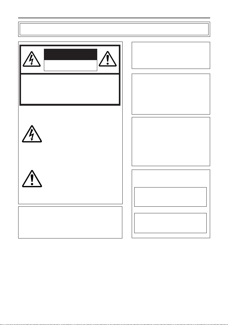
Safety Precautions
CAUTION
RISK OF ELECTRIC SHOCK
DO NOT OPEN
CAUTION:TO REDUCE THE RISK OF ELECTRIC
Information for USA
This device complies with part 15 of the FCC
Rules. Changes or modifications not approved by
JVC could void the user’s authority to operate the
equipment.
SHOCK. DO NOT REMOVE COVER (OR
BACK). NO USER-SERVICEABLE PARTS
INSIDE.REFER SERVICING TO
QUALIFIED SERVICE PERSONNEL.
The lightning flash with arrowhead
symbol, within an equilateral triangle
is intended to alert the user to the
presence of uninsulated "dangerous
voltage" within the product's enclosure that may be of sufficient magnitude to constitute a risk of electric
shock to persons.
The exclamation point within an equilateral triangle is intended to alert the
user to the presence of important operating and maintenance (servicing)
instructions in the literature accompanying the appliance.
Due to design modifications, data
given in this instruction book are
subject to possible change
without prior notice.
WARNING:
TO REDUCE THE RISK OF
FIRE OR ELECTRIC SHOCK,
DO NOT EXPOSE THIS
APPLIANCE TO RAIN OR
MOISTURE.
AVERTISSEMENT:
POUR EVITER LES RISQUES
D’INCENDIE OU D’ELECTROCUTION, NE PAS EXPOSER
L’APPAREIL A L’HUMIDITE OU A
LA PLUIE.
INFORMATION (FOR CANADA)
RENSEIGNEMENT
This Class A digital apparatus
complies with Canadian ICES-
003.
Cet appareil numérique de la
Class A est conforme à la
norme NMB-003 du Canada.
(POUR CANADA)
2
Page 3
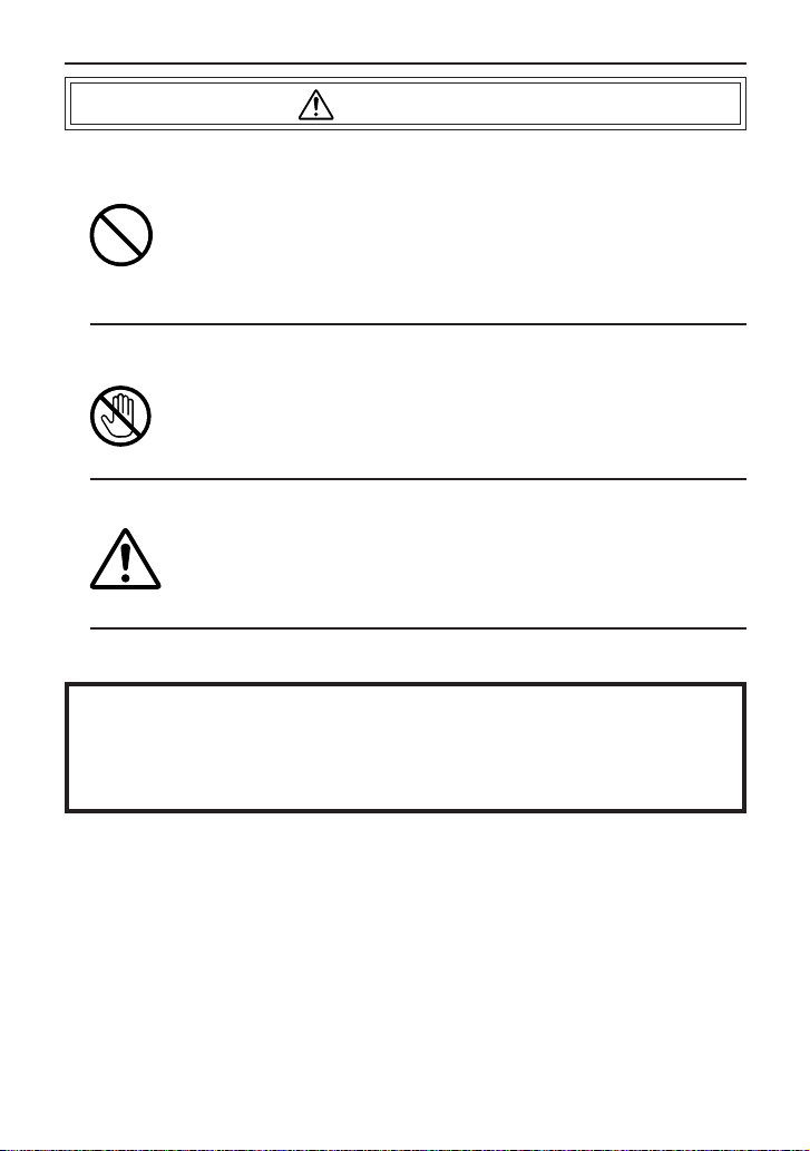
WARNING
■ Keep away from moisture
Fire or electrical shock can result from the presence of moisture.
Spillage can occur from objects containing water (flower
vases, flower pots, cups, cosmetics, pharmaceuticals, etc.)
and should not be placed on top of this device.
■ Do not touch
Do not touch lines (antenna wires, phone lines, etc.) connected to this device or power plugs during a thunder storm
because this can result in electrical shock.
■ When installing this device, maintain a space of 10cm or
more between this device and the wall. Also keep other devices at a distance to ensure good radiation. Internal heat
can result in fire.
Warning
This is a class A product. In a domestic environment this product may
cause radio interference in which case the user may be required take
adequate measures.
3
Page 4
PRECAUTIONS FOR SAFE AND PROPER USE
To ensure safety
■ Always observe the following to ensure correct and safe usage of this device.
Read Safety Precautions thoroughly before using this device. The safety precautions
contain important information and should always be observed.
After reading, store in a readily available location for future reference.
Regarding Symbol Indications
Numerous symbols are employed as indication in the precautions for safety,
precautions for handling, and in the indication to the products. These are designed to
prevent in advance any possible infliction of injury on you and other individuals and
the damage of properties through the proper use of the product. The symbols and
meanings are shown below. Grasp the contents of the symbols completely before
reading this manual.
This represents the contents in which the probabilities
WARNING
CAUTION
for death or serious injury are assumed if this symbol
indication is ignored and the product is erroneously
handled.
This represents the contents in which the probabilities
for injury to be inflicted are assumed and the contents in
which material damages to be sustained are assumed if
this symbol indication is ignored and the product is
erroneously handled.
Examples of Symbol Indications
This symbol informs you of the presence of the contents that
demands caution (including danger and warning). Specifically
prohibited contents (caution against electric shock in case of the left
symbol) are illustrated in the symbol.
This symbol informs you of prohibited actions. Specifically prohibited
contents (prohibition of disassembly in case of the left symbol) are
illustrated in the symbol and its vicinity.
This symbol informs you of the contents that forces you to take some
action or gives you some guidelines or instructions. Specific contents
of instructions (unplug the power cord from the outlet in case of the
4
left symbol) are illustrated.
Page 5
Cautions
■ Do not install this device in locations such as the following.
To avoid the possibility of fire or electrical shock, do not install this
device in locations such as the following.
• Where there is excessive humidity or dust.
Do not install where there is excessive humidity or dust.
Avoid locations with oil smoke or steam.
• Locations where temperatures are high.
Do not install in locations where temperatures are extremely high
due to direct contact with sunlight or proximity to a heater.
■ Do not connect or disconnect the power cord or plug with wet
hands because this can result in electrical shock.
■ Do not place heavy objects on top of this device.
Loss of balance could cause falling and result in injury or damage.
■ Do not stand on this device.
This could cause overturning and result in injury or damage. Use special
caution with children.
■ Use only the specified accessories.
Use only the accessories specified in the instruction manual with this
device. The use of other accessories can result in fire or electrical shock.
■ Have your local dealer perform an internal inspection once every
three years.
Accumulated dust inside this device can eventually result in fire or
malfunction if not removed periodically. It is more effective to have this
inspection performed before the rainy season and when humidity is
high. Consult your local dealer concerning the inspection fee.
■ The power IN jack is exposed, so use caution to avoid shorting with metal
objects, etc., when connecting and disconnecting the power cable.
■ Do not allow children with the carton and bags used for packing because
this could result in suffocation.
■ Do not connect any device that exceeds the ratings to the Alarm jack
because this may damage the main unit.
5
Page 6

Cautions
• This instruction manual may not be reproduced in part or in its entirety.
• Use caution to avoid infringing the copyrights of others during use.
• Please note that this company does not assume any responsibility in the
case of any possible errors that may be found in this instruction manual.
• The contents of this instruction manual are subject to change without notice.
• When this product is discarded, always observe all applicable laws and
regulations.
Trademarks
Microsoft and Windows are registered trademarks of Microsoft Corporation
of the U.S. in the U.S. and other countries.
The marks ™, ©, ®, etc., are not used in this instruction manual.
Any other company names and product names mentioned in this
instruction manual are the trademarks or registered trademarks of the
respective companies.
Before Saving Important Images
• Due to provisions of the copyright law, images recorded and saved from
TV broadcasts and recorded tapes, etc., and recorded and saved images
of printed materials such as posters, etc., cannot be used for any purpose
other than personal enjoyment without the express written permission of
the copyright holder.
• When recording important images, always make test shots beforehand to
make sure that recording and display are correct. Also use caution
concerning available hard disk capacity.
• Please note that compensation will not be paid in the case that normal
recording and playback are not possible due to problems with this product
or with the computer software, etc.
6
Page 7

Contents
Safety Precautions ...................................................................................... 2
Package Contents ....................................................................................... 8
Operating Environment .............................................................................. 9
VN-C3WU Installation and Setup...............................................................11
Before starting installation and setup ....................................................11
Names of VN-C3WU parts.....................................................................11
Installation and setup ............................................................................ 12
Alarm IN/OUT connection.......................................................................... 14
Setting the VN-C3WU IP address ............................................................. 15
Changing the IP address of the PC ...................................................... 15
Changing internal settings .................................................................... 17
Restore to the orlginal PC IP address .................................................. 2 2
VN-C3WU connection test ........................................................................ 22
VN-C3WU / Web page .......................................................................... 24
Top page................................................................................................ 24
Still image page..................................................................................... 25
Live image page.................................................................................... 25
Control page.......................................................................................... 26
Control Window..................................................................................... 27
Setting page .......................................................................................... 31
How to link the VN-C3WU images ............................................................ 38
Displaying live images .......................................................................... 38
Displaying live images .......................................................................... 38
Troubleshooting ......................................................................................... 40
Specifications............................................................................................. 42
7
Page 8

Package Contents
This product includes all of the following items. If any item should be missing, please contact your
local dealer.
VN-C3WU main unit
Instruction manual (this document)
8
Page 9

Operating Environment
The environment described below is necessary for operation of the VN-C3WU.
A personal computer running the following WWW browser software:
WWW browser software that is compatible with JavaScript or Frame. Netscape 4.0 or
higher, or Internet Explorer 4.0 or higher, is required.
CPU performance and memory capacity should be the recommended values for the
WWW browser software used. To ensure the smooth display of animated images on a
large screen, these values should be even larger than those recommended.
Also, images from the camera will not be correctly displayed in the 256-color mode,
etc.
• In the case of Internet Explorer, an environment in which JAVA can be executed
correctly is necessary.
LAN environment
The VN-C3WU operates as a web browser using HTTP protocol.
Access linking by host name is possible with an environment able to use DNS (Domain
Name System).
Caution
The standard used for connection to the VN-C3WU is 10BASE-T.
The VN-C3WU and a personal computer can be connected directly at 1: 1 by using
cross cables. (Although rare, the use of cross cables is not possible with some LAN
boards.)
9
Page 10

To ensure correct usage
● When installing, avoid the following.
• Locations subject to rain and water.
• Locations where the ambient temperature exceeds the range of 0 - 40
(recommended) degrees C.
• Locations with vibration.
• Locations with excessive dust, oil or gas.
● When this product is used with AGC on (Auto on), the sensitivity will be
increased automatically in dark places, so the screen may flicker in some
cases. This is not a malfunction.
● When this product is used with Auto on, in some cases the recorded colors
may differ slightly from the natural colors due to the principle of the automatic
tracking color balance circuit.
● When any bright object such as a lamp, etc., is photographed, white bands
may appear above and below the bright object. This is called smearing, a
phenomenon caused by the characteristics of the individual pixels, and is
not a malfunction.
● When panning and tilting the VN-C3WU, do not apply force to any part
other than the body because this could result in damage or a malfunction.
● Use caution to avoid catching on the sensor insert button of the alarm
input/output jack. In case this happens and disconnection from the alarm
input/output jack occurs, return to the original location and use there.
10
Page 11
VN-C3WU Installation and Setup
Before starting installation and setup
It is necessary to set an IP address for each VN-C3WU unit. Use the following procedure for the
setup of individual units. (If the power is not turned on, the installation operation can be performed
at one time.)
1. Install the VN-C3WU.
Only in cases of installation in a location where the power cannot easily be turned on,
complete steps 2 to 4 before installing.
2. Connect the VN-C3WU to a network.
(With the VN-C3WU power turned on.)
3. Set the VN-C3WU IP address.
When setting the VN-C3WU IP address, be sure to contact the network manager for
assignment or approval.
4. Alarm IN/OUT connection.
5. VN-C3WU access test.
This test is performed after any change to confirm the IP address.
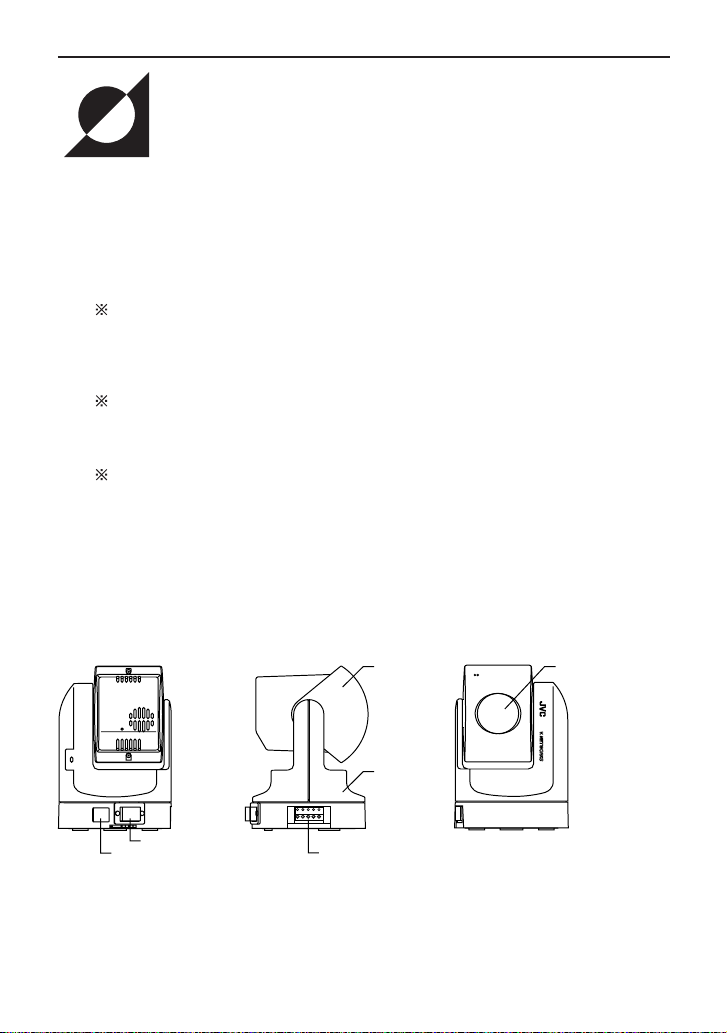
Names of VN-C3WU parts
Rear view
10BASE-T10BASE-T
DC12VDC12V
DC IN jack
10BASE-T port
Side view
Alarm IN/OUT jack
Body
Front view
Lens coverLens unit
11
Page 12
Installation and setup
1. Installation
Use the optional bracket (Model VN-BK30) for installation.
Make the power and network connections after completion of the installation work.
Caution
Install in a location with sufficient strength to prevent falling.
VN-C3WU units can be installed as shown in the diagram below.
1 Attach the ceiling fixer with the P hole
pointing toward the front of the camera.
3 Attach the drop-prevention wire of the
ceiling fixer to the camera body fixer.
drop-prevention wire
V.NETWORKS
2 Mount the camera body fixer
on the VN-C3WU.
V.NETWORKS
4 Mount the VN-C3WU on the ceiling fixer
by rotating clockwise, then tighten the
screw of the camera body fixer.
12
Page 13

2. Connecting to a network
Turn on the power of only one VN-C3WU unit.
When network connection is completed and the power is turned on, the
VN-C3WU unit will be connected to the network at the following IP address.
Factory set (Default) IP address 192. 168. 0. 2
❉ Use a straight cable when
connecting to a hub.
Use a cross cable when
connecting directly to a PC.
Power supply connection cable
● About the power supply connection cable
• Length: 30m or less.
• Recommended model: UL1007, UL1015 or equivalent cable with wire
equivalent to ID AWG #20 or larger.
Caution
All VN-C3WU units are set to the same IP address at the factory; therefore,
if the power of multiple VN-C3WU units is turned on at the same time,
address duplication will occur and correct access will not be possible. Always
turn the power on for only one unit at a time. If address duplication occurred,
perform the proper processing and wait for 10 min. or more, or turn off the
power of all units on the network and then turn the power on again;
otherwise, correct access may not be possible.
Caution
VN-C3WU unit is intended to be Supplied by a Listed Direct Plug-In Power
Unit marked “Class 2” and rated from 11 to 15 V dc, 2 to 2.5 A.
13
Page 14
3.Alarm IN/OUT connection
Connect external devices to the alarm IN/OUT as shown below.
Sensor insert button
External
device
OUT 1
● Cable connection and disconnection
Press the sensor insert button when connecting and disconnecting cables.
After connecting or disconnecting, make sure the sensor insert button
returns to its original position.
● About the alarm IN/OUT connection cables
• Length: use cables with a length of 50m or less.
• Recommended model: UL1007, UL1015 or equivalent cable with wire
equivalent to AWG #22 - AWG #18.
Caution
External noise may affect the alarm working properly even with a cable
length of 50m or less. In such cases, it is necessary to either change to the
use of shielded cable to prevent influence by noise or to change the wiring
route to avoid passing close to the source of the noise.
14
External
device
OUT 2
External
device
IN
Page 15

4. Setting the VN-C3WU IP address
4-1 Changing the IP address of the PC
Display the network settings panel by selecting Settings from the Start
button, then selecting Control Panel and Network, in that order.
1 Select the TCP/IP item, then click
on Properties.
2
Before making a change, always
make a note of the original IP
address.
Change the IP address to
192.168.0.3.
Set the subnet mask to a value
suitable for the setting operation. If
the value is unknown, check with the
3 Click on OK and then
reboot the PC.
network administrator.
15
Page 16

About the web pages mentioned in this instruction
manual
From the following page, all the screens expressed as VN-C3WU pgae are contained in VNC3WU and displayed by the web page browse and display function of the WWW browser
software.
Therefore depending on WWW browser software and its settings, the formats and fonts may be
different from the screens of VN-C3WU page, in this manual.
In this manual, all the screens of VN-C3WU are displayed by the web page browse and display
function of Netscape.
16
Page 17

4-2 Changing internal settings
Start the WWW browser software.
Specify the factory-set VN-C3WU web page address in the browse location in the WWW
browser software. (When the factory-set IP address is specified, the WWW browser software
will display the VN-C3WU top page.)
http://192.168.0.2/
Caution
Caution
In some cases, direct specification is not possible when a proxy server has
been set for Internet access. In such cases, contact the network administrator
and change the setting.
WWW browser software (using Netscape as an example)
17
Page 18

Display of the VN-C3WU top page.
The Settings page is displayed.
VN-C3WU top page.
Click on Settings.
VN-C3WU Settings page.
18
Page 19

Setup is performed by changing the "Other Settings" contents.
VN-C3WU Settings page "Other settings"
Other Settings
[IP address]
Change to an IP address assigned or approved by the network administrator.
[Subnet mask]
Like the IP address, the subnet mask is assigned or approved by the network administrator.
[Default Gateway]
Set the default Gateway IP address. 0.0.0.0 means the gateway is not used.
[Host name]
• Specify using up to 8 letters. Only in the environment to use DNS (Domain Name System)
and make the access link by host name. Except for this environment, do not specify anything.
[MAC address]
This is the unique physical address of the product.
Cannot be changed.
19
Page 20

Other Settings
[Program version]
The version of the VN-C3WU main unit firmware.
Cannot be changed.
[Power Frequency]
This setting reduces the amount of flicker under fluorescent lighting. Set to 50Hz or 60Hz in
accordance with the power frequency at the installation location.
[Password]
Specify using up to 8 letters. Enter (re-enter) the same password two times in each level for
confirmation purposes.
[Auto Refresh]
Specify Pan/Tilt position display in the (Control page) and (Configration page) is automatically
refreshed or not.
[Cache Settings]
Only a few of the proxy servers in Cache Settings cache Cgi; therefore, Pan/Tilt control
occasionally does not operate correctly. In such cases, check Cache Disable.
Password function
An access protection using a password is provided to regulate connecting PCs (users)
connected to the VN-C3WU. This access protection function has three levels to match the
access levels. The pages that can be accessed at each of these levels are as shown below.
(Refer to page 22 for the VN-C3WU web page configuration.)
Password level
User level
Operator level
Administrator level
Still Image page and Live Image page.
The above pages and (Pan/Tilt) control page.
The above pages and Settings page.
Accessible page
Caution
Never forget the current password because the password setting cannot
be changed unless it matches the Administrator level password.
Caution
A password will not be requested when only a user level or operator level
password has been set but an administrator level password has not been
set.
20
Page 21

VN-C3WU Settings page "Other Settings"
Press Apply button to enable the setting.
Check the new IP address again.
If there is no mistake in the entry, click on OK.
Caution
The confirmation screen shown above will appear when the IP address,
subnet mask, host name and power frequency settings are changed.
When OK is clicked in this confirmation screen, the VN-C3WU main unit
internal preset operation will be performed and the IP address, etc., will be
changed. The Factory set (Default) IP address of 192.168.0.2 will become
invalid, and the connection to the VN-C3WU will be no longer possible.
When the WWW browser software is not operated for a certain time, a
message indicating that connection is not possible will appear as a result
of IP address change.
21
Page 22

4-3 Restore to the original PC IP address
Using the same procedure as described in item 4-1, select Settings from the Start button,
then select Control Panel and Network, in that order. Next, restore to the original IP
address and reboot the PC in accordance with the messages.
5. VN-C3WU connection test
This test confirms whether or not each VN-C3WU web page can be displayed with the WWW
browser software using the set IP address or DNS host name.
(Refer to page 24 for the VN-C3WU web page configuration.)
Caution
In some cases, direct specification is not possible when a proxy server
has been set for Internet access. In such cases, contact the network
administrator and change the settings.
Also contact the network administrator and make necessary settings
regarding DNS address for using DNS.
Enter http:// IP Address or Host name /
22
Page 23

Enter the User Name and Password.
Enter a password.
It is not necessary to enter a user name.
Click on OK.
In order to assure quick display of the VN-C3WU web page from the WWW browser being
used, register a browse location (URL : Uniform Resource Locator) is recommended.
Use Bookmarks with Netscape or Favovites with Internet Explorer for this registration.
Addition to Bookmarks (using Netscape).
23
Page 24

VN-C3WU/Web page
Explanation of display items and operations
The following is a diagram of the configuration of the VNC3WU internal URL (web pages).
Caution
In order to access all the VN-C3WU web pages, the Administrator level password is required.
Password level
USER OPERATOR
Top page (index_e.html)
Still image page (still_e.html)
Live image page (java_e.html or spush_e.html)
ADMINISTRATOR
Still iamge (still.jpg)
Server Push live image URL
(push.jpg)
Java live image URL
(mjpeg.class)
Top page: http://
The purpose of this page is to link to each of the VN-C3WU web pages.
Buttons to link each page. (use a singal click)
index_e.html. (
*****
*****
Control page
(spushcontrol_e.html
or javacontrol_e.html)
is the URL of the VN-C3WU.)
VN-C3WU top page
Still image
When browsing is started.
24
Settings page
(spushconfig_e.html
or
javaconfig_e.html)
Page 25

Still image page: http://
This page is to display a still image when browsing is started. To update the image, use the
Reload or Refresh function of the WWW browser software. To save the image being displayed,
use the Save as... function of the WWW browser software.
still_e.html. (
*****
Hyper link to the top page.
is the URL of the VN-C3WU)
*****
VN-C3WU still image page
Live image page:
Netscape http://
Internet Explorer http://
(
This page is to display live images. The camera images are updated automatically and displayed
as live images.
The URL will be changed automatically by the WWW browser software.
/spush_e.html
*****
/jave_e.html.
*****
is the URL indicated by the VN-C3WU)
*****
Caution
The Save as... function of the WWW browser software cannot be used with this page so
do not attempt to save. The Save as... function cannot be used for the entire web page so
do not attempt to save.
Caution
Server push images are cached in the browser; therefore, operation of the browser may
become sluggish after continuous use for an extended time period.
In such cases, set caching by the browser to off.
VN-C3WU live image page
ve
Hyper link to the top page.
25
Page 26

Control page:
Netscape http://
Internet Explorer http://
(
This page is to control Pan/Tilt operations and to operate the position memory.
The images are updated automatically and displayed as live images.
The URL will be changed automatically by the WWW browser software.
/spushcontrol_e.html
*****
/javacontrol_e.html.
*****
is the URL of the VN-C3WU)
*****
Caution
Perform the Pan/Tilt operations after all images have been loaded into the web browser.
VN-C3WU control page
Live image
Hyper link to other pages.
VN-C3WU data display area
The current Pan/Tilt position is displayed.
Warning messages for operations are
also displayed.
A window is displayed for
setting pan, tilt, zoom,
position memory shift and
position memory.
26
A window is displayed for
setting the iris, focus and
zoom.
Page 27

Control Window
When the Control Page is opened, the sub-window shown below will be
displayed for setting pan, tilt, zoom, position memory shift and position memory .
Caution
Always perform Pan/Tilt operations after all button images have been read
by the browser.
27
Page 28

Pan/Tilt/Zoom control
The current Pan/Tilt angle step and Zoom step are displayed
here. Angles (integer value) can be changed by entering value
and clicking on the Apply button.
The Pan/Tilt can be controlled with the 8 Pan/Tilt
operation buttons.
The amount of movement for each operation of
Pan/Tilt is the above Pan/Tilt Angle.
The lens zoom ratio
can be changecd
by using the two
operation buttons.
The amount of
change each time
one of the zoom
operation buttons is
displayed in "zoom"
step.
28
Page 29

Lens setting window
Zoom
Operates the zoom.
Zoom-in and zoom-out are performed by changing the value and clicking
on the Apply button.
Focus
Adjusts the focus.
When set to Auto (auto-focus), focus will be adjusted automatically.
When set to Manual, focus will be manually adjusted.
(The focus position can be set by changing the value on the right and
clicking on the Apply button.)
Iris
When set to Auto, the iris (aperture) will be adjusted automatically in
accordance with the subject brightness. Auto iris can be adjusted by
changing the value to the right (default value: 8).
When set to Manual, the iris will be adjusted to the specified value,
regardless of the subject brightness. (Change the value on the right and
click on the Settings button.)
29
Page 30

Position memory movement
The VN-C3WU is equipped with 10 position
memories.
VN-C2WU control page (position memory control)VN-C2WU control page (position memory control)VN-C3WU control page (position memory control)
Position memory setting
The contents of the currently set position memory
are displayed.
VN-C2WU control page (position memory setting)VN-C2WU control page (position memory setting)VN-C3WU control page (position memory setting)
30
The current Pan/Tilt/Zoon position can be set to
any of the 10 position memories by clicking on
"Apply".
Page 31

Settings Page:
Netscape http://
Internet Explorer http://
(
This page is to make the camera image related settings and connection (setup) related settings.
(The images are updated automatically and displayed as live images.)
The URL will be changed automatically by the WWW browser software.
/spushconfig_e.html
*****
/javaconfig_e.html.
*****
is the URL of the VN-C3WU)
*****
VN-C3WU settings page
Hyper link to other pages
Live image.
VN-C3WU data display area
The current Pan/Tilt/Zoom position is
always displayed. Warning messages for
the various operations are also displayed.
31
Page 32

Control Window
Refer to the Control Page explanation.
Image Quality Settings Window
Camera auto/
manual setting.
Image quality
related menu
32
Page 33

Camera Auto/Manual Settings
VN-C3WU settings page
(Auto/manual settings)
Manual :
Auto :
“Quality” in “Image Quality Setting” such
as Saturation and Color Balance can be
manually set.
“Quality” in “Image Quality Setting” can
be automatically set.
Select Auto or Manual depending on
operational environment.
Click Apply after selecting Auto or
Manual.
Image Quality Setting
VN-C3WU settings page
(Image Quality setting)
Also effective when
Auto is set.
Clicking Default returns all of
the settings to the factory set
values (Default values).
After making each setting,
click Apply to change the
VN-C3WU internal settings.
33
Page 34

Image Quality menu
[Resolution]
Three different image sizes are available: 640 x 480, 320 x 240 and 160 x
120.
[Compression Rate]
The compression ratio has an inversely proportional relationship to image
quality but increasing the compression ratio increases the number of frames
that can be displayed per second.
Compression ratio Low Medium High
Image quality High Medium Low
No. of frames Low Medium High
[Frame Rate]
Frame rate sets the upper limit for the number of image frames sent from the
VN-C3WU per second.
(fps is the abbreviation for frames per second)
[Frame Rate]
Frame rate sets the upper limit for the number of image frames sent from the
VN-C3WU per second.
(fps is the abbreviation for frames per second)
Caution
If the frame rate is not set to 1fps or less in the band below 10Mbps, the
pan/tilt operations may not be possible from the control page in some cases.
(ISDN 64k, 128k, analog 56k, etc., are pertinent.)
Caution
The number of frames actually sent and displayed per second depends on
the performance of the personal computer and WWW browser software,
and on the LAN environment, etc. When communication interference from
processing being performed by other users is anticipated (especially in
environments where the load on the network is relatively heavy), it is
advisable to set a low value for the frame rate.
Quality
Image Sensor can be used when Camera Auto/Manual Setting is set to
Manual. (Excluding the “Saturation” and the “Color Balance”.)
Images can be adjusted by changing the detail items.
34
Page 35

Item
Saturation
Color Balance
Effect
Adjustment of the color saturation.
Also effective when Auto is set.
(The larger the setting value, the greater the color
saturation.)
Move the slide Adjustment of the tone.
Also effective when Auto is set.
(50 is the median value. Decreasing the settingvalue
emphasizes red and increasing the settingvalue
emphasizes blue.)
Brightness
Contrast
Gain
[Other Settings]
This the Auto/Adjustment of the image brightness.
(The larger the setting value, the greater the
brightness.)
Adjustment of the contrast. (The larger the setting value,
the stronger the contrast.)
Adjustment of the gain of the internal amp.
(Increase the setting value when light is
insufficient.)
VN-C3WU settings page
(Other Settings)
Most of the items are set during installation and setup. Refer to page 19 for details.
35
Page 36

Alarm Settings Window
Sets the VN-C3WU operation when an alarm signal is input.
Alarm 1/2 Input
On/Off -------------Set to On when the alarm input jack (alarm 1/2) is to be
used; set to Off when the alarm jack not to be used.
Setting------------- The position memory shift and alarm output to the position
memory can be set when an alarm is input.
- Shift to a specified position
Sets position memories 1 - 10 set from the Control Page.
When an alarm is input, a shift is made to the specified position.
- Alarm output
When an alarm is input while set to Yes, the signal set with Output
Alarm will be output from the Alarm Out jack.
36
Page 37

Relay Alarm Input
The input of an alarm a few seconds after a previous alarm has been input
can be set separately as a relay alarm.
Alarm Out
On/Off -------------Set to On when alarm output is to be used; set to Off when
alarm output is not to be used.
Setting Items ---- Sets the signal to be output from the Alarm Output jack.
- Momentum output
Sets the time during which alarm output is to continue.
- Output value
Sets either the High signal or Low signal as the alarm output.
- Initial output at power on
Sets whether or not to output an alarm signal one time from the
VN-C3WU alarm output when the power is turned on,
Set the output in accordance with the device which will receive the alarm.
After setting the alarm, always make sure that alarm operation is normal.
37
Page 38

How to link the VN-C3WU images
The still or live mages of VN-C3WU can be pasted and displayed in a
separate web page you have created.
Displaying still image:
A still image can be displayed by creating a web page with the contents
described below.
<IMG SRC="http://
/still.jpg">
*****
shows the URL indicated by the VN-C3WU.
*****
Displaying live images:
Two methods can be used for live images: the Serverpush method and the
Java method.
It is necessary to use one of these methods in accordance with the WWW
browser software compatability.
Displaying with Serverpush
Live images can be displayed with Serverpush-compatible WWW browser
software (Netscape) by creating a web page with the contents described
below.
<IMG SRC="http://
/push.jpg">
*****
indicates the VN-C3WU IP address.
*****
38
Page 39
Displaying with Java
Live images can be displayed with Java-compatible WWW browser
software (Internet Explorer, etc.) by creating a web page with the contents
described below.
<APPLET CODE="mjpeg.class"WIDTH=640 HEIGHT=480
CodeBase=http://
/"></APPLET>
*****
indicates the VU-C3WU IP address.
*****
Caution
The resolution, compression rate, etc., of both the still and live images
browsed and displayed (in a separate web page are) in accordance with
the previously set setting values.
Also, correct display may not be possible if Java execution is disabled with
the WWW browser software.
Caution
When a password has been set, animated images cannot be displayed
with JAVA without prior confirmation.
Caution
Set "Width" and "Height" to the same values used for the resolution of VN-C3WU
39
Page 40

Troubleshooting
The IP address to which
the VN-C3WU was
changed has been
forgotten.
The password protection
was set but the password
was forgotten.
Color balance is
unsatisfactory.
Unknown IP addresses are handled as
repairs. Please consult your local dealer.
Disabling of the password protection function
is handled as a repair. Please consult your
local dealer. Be prepared to show proper
identification for safety purposes.
• Check the display and video card color
adjustments.
Color balance will vary slightly, depending
on the personal computer, video card and
monitor display used. Improvement is
sometimes possible by adjusting the color
settings of the monitor display. Also,
depending on the video card used, the
colors can sometimes be adjusted by right
clicking the mouse on the desktop to access
"Screen Properties."
• Color balance is sometimes unnatural when
a True Color (24-bit) display is switched to
High Color (16-bit). The use of True Color
is recommended.
• Adjust Color Balance.
Color balance can be adjusted by using the
Color Balance item in the Image Menu in
the VN-C3WU Settings page.
40
(Cont'd on the next page.)
Page 41

Color balance is
unsatisfactory.
• Try changing the Camera Auto/Manual
setting in the VN-C3WU Settings Page from
Auto to Manual, and then back to Auto
again.
When changing between scenes with
different light sources (for example, when
moving from outdoors with sunlight to
indoors with fluorescent lighting), there may
be a slight delay before the automatic
tracking white balance function starts to
operate.
Depending on the subject, the color balance
may appear to change slightly . This is not a
malfunction.
This product uses auto white balance. When
most of a subject is red, blue-green areas
may appear bluish; blue areas may appear
orange; and yellow areas may appear bluepurple. In such cases, use the color balance
image quality setting to adjust the color
matching.
Image size and position
change spontaneously.
Focus is not accurate. The autofocus may not be accurate in dark
This sometimes appears to be the case when
multiple operators and administrators have
access to one VN-C3WU unit and change the
settings because the last settings made will
still be in effect for the next user.
places and in locations without features, such
as a wall, etc. In such cases, adjust the focus
manually.
Focus may be slightly off when adjusted
manually at the TELE setting. This is not a
malfunction.
Due to its principle of operation, autofocus is
difficult with striped subjects.
41
Page 42

Specifications
LAN standard IEEE 802.3
Communication protocol TCP/IP, HTTP
Video element 1/3-inch, 300,000-pixel CMOS image sensor.
Minimum focusing distance 1.0m
Pan/tilt operation angle Pan: 320°
Tilt: 90°
Output image format 640 × 480, 320 × 240, 160 ×120
Power supply voltage DC 12V
Power consumption 2.0A (max.)
Operating temperature 0°C — 40°C
Mass (weight) Approx. 730g.
Alarm input Non-voltage a contact input
Low level. latch/momentary (500ms or more)
Low level circuit current 1mA
High level impressed voltage 5V
Alarm output NPN open collector output (allowable impressed
voltage: 12V; allowable input current: 300mA)
External dimensions (Unit: mm)
With VN-BK30 installed
10BASE-T
42
Page 43

43
Page 44

VICTOR COMPANY OF JAPAN, LIMITED
VN-C3WU V.NETWORKS
COPYRIGHT © 2000 VICTOR COMPANY OF JAPAN, LTD.
Printed in Japan
SS961552-001
 Loading...