

Page 1
2
CAUTION:TO REDUCE THE RISK OF ELECTRIC
SHOCK. DO NOT REMOVE COVER (OR
BACK). NO USER-SERVICEABLE PARTS
INSIDE.REFER SERVICING TO
QUALIFIED SERVICE PERSONNEL.
The lightning flash with arrowhead
symbol, within an equilateral triangle
is intended to alert the user to the
presence of uninsulated "dangerous
voltage" within the product's enclosure that may be of sufficient magnitude to constitute a risk of electric
shock to persons.
The exclamation point within an equilateral triangle is intended to alert the
user to the presence of important operating and maintenance (servicing)
instructions in the literature accompanying the appliance.
RISK OF ELECTRIC SHOCK
DO NOT OPEN
CAUTION
Information for USA
This device complies with part 15 of the FCC
Rules. Changes or modifications not approved by
JVC could void the user’s authority to operate the
equipment.
Due to design modifications, data
given in this instruction book are
subject to possible change
without prior notice.
AVERTISSEMENT:
POUR EVITER LES RISQUES
D’INCENDIE OU D’ELECTROCUTION, NE PAS EXPOSER
L ’APP AREIL A L’HUMIDITE OU A
LA PLUIE.
Safety Precautions
INFORMATION (FOR CANADA)
RENSEIGNEMENT (POUR CANADA)
WARNING:
TO REDUCE THE RISK OF
FIRE OR ELECTRIC SHOCK,
DO NOT EXPOSE THIS
APPLIANCE TO RAIN OR
MOISTURE.
This Class A digital apparatus
complies with Canadian ICES-
003.
Cet appareil numérique de la
Class A est conforme à la
norme NMB-003 du Canada.
VM-C3UE.65J 00.4.7, 5:34 PM2
Page 2
3
■ Keep away from moisture
Fire or electrical shock can result from the presence of moisture.
Spillage can occur from objects containing water (flower
vases, flower pots, cups, cosmetics, pharmaceuticals, etc.)
and should not be placed on top of this device.
■ Do not touch
Do not touch lines (antenna wires, phone lines, etc.) connected to this device or power plugs during a thunder storm
because this can result in electrical shock.
■ When installing this device, maintain a space of 10cm or
more between this device and the wall. Also keep other devices at a distance to ensure good radiation. Internal heat
can result in fire.
WARNING
Warning
This is a class A product. In a domestic environment this product may
cause radio interference in which case the user may be required take
adequate measures.
VM-C3UE.65J 00.4.7, 5:34 PM3
Page 3
4
PRECAUTIONS FOR SAFE AND PROPER USE
This symbol informs you of the presence of the contents that
demands caution (including danger and warning). Specifically
prohibited contents (caution against electric shock in case of the left
symbol) are illustrated in the symbol.
This symbol informs you of prohibited actions. Specifically prohibited
contents (prohibition of disassembly in case of the left symbol) are
illustrated in the symbol and its vicinity.
This symbol informs you of the contents that forces you to take some
action or gives you some guidelines or instructions. Specific contents
of instructions (unplug the power cord from the outlet in case of the
left symbol) are illustrated.
Regarding Symbol Indications
Examples of Symbol Indications
WARNING
This represents the contents in which the probabilities
for death or serious injury are assumed if this symbol
indication is ignored and the product is erroneously
handled.
This represents the contents in which the probabilities
for injury to be inflicted are assumed and the contents in
which material damages to be sustained are assumed if
this symbol indication is ignored and the product is
erroneously handled.
Numerous symbols are employed as indication in the precautions for safety,
precautions for handling, and in the indication to the products. These are designed to
prevent in advance any possible infliction of injury on you and other individuals and
the damage of properties through the proper use of the product. The symbols and
meanings are shown below. Grasp the contents of the symbols completely before
reading this manual.
CAUTION
■ Always observe the following to ensure correct and safe usage of this device.
Read Safety Precautions thoroughly before using this device. The safety precautions
contain important information and should always be observed.
After reading, store in a readily available location for future reference.
To ensure safety
VM-C3UE.65J 00.4.7, 5:34 PM4
Page 4
5
■ Do not install this device in locations such as the following.
To avoid the possibility of fire or electrical shock, do not install this
device in locations such as the following.
• Where there is excessive humidity or dust.
Do not install where there is excessive humidity or dust.
Avoid locations with oil smoke or steam.
• Locations where temperatures are high.
Do not install in locations where temperatures are extremely high
due to direct contact with sunlight or proximity to a heater.
■ Do not connect or disconnect the power cord or plug with wet
hands because this can result in electrical shock.
■ Do not place heavy objects on top of this device.
Loss of balance could cause falling and result in injury or damage.
■ Do not stand on this device.
This could cause overturning and result in injury or damage. Use special
caution with children.
■ Use only the specified accessories.
Use only the accessories specified in the instruction manual with this
device. The use of other accessories can result in fire or electrical shock.
■ Have your local dealer perform an internal inspection once every
three years.
Accumulated dust inside this device can eventually result in fire or
malfunction if not removed periodically. It is more ef fective to have this
inspection performed before the rainy season and when humidity is
high. Consult your local dealer concerning the inspection fee.
■ About CD-ROM handling
Do not bend or fold CD-ROMs.
■ The power IN jack is exposed, so use caution to avoid shorting with metal
objects, etc., when connecting and disconnecting the power cable.
■ Do not allow children with the carton and bags used for packing because
this could result in suffocation.
Cautions
VM-C3UE.65J 00.4.7, 5:34 PM5
Page 5

6
Cautions
• This instruction manual may not be reproduced in part or in its entirety.
• Use caution to avoid infringing the copyrights of others during use.
• Please note that this company does not assume any responsibility in the
case of any possible errors that may be found in this instruction manual.
• The contents of this instruction manual are subject to change without notice.
• When this product is discarded, always observe all applicable laws and
regulations.
Trademarks
Microsoft and Windows are registered trademarks of Microsoft Corporation
of the U.S. in the U.S. and other countries.
The marks ™, ©, ®, etc., are not used in this instruction manual.
Any other company names and product names mentioned in this
instruction manual are the trademarks or registered trademarks of the
respective companies.
Before Recording or Saving Important Images
• Due to provisions of the copyright law, images recorded and saved from
TV broadcasts and recorded tapes, etc., and recorded and saved images
of printed materials such as posters, etc., cannot be used for any purpose
other than personal enjoyment without the express written permission of
the copyright holder.
• When recording important images, always make test shots beforehand to
make sure that recording and display are correct. Also use caution
concerning available hard disk capacity.
• Please note that compensation will not be paid in the case that normal
recording and playback are not possible due to problems with this product
or with the computer software, etc.
VM-C3UE.65J 00.4.7, 5:34 PM6
Page 6

7
Contents
Safety Precautions ..................................................................................................... 2
About New Versions ....................................................................................................8
Package Contents and Operating Environment .........................................................8
VN-C3U Installation and Setup ................................................................................ 10
Before starting installation and setup ................................................................. 10
Names of VN-C3U parts ..................................................................................... 10
Installation and setup .......................................................................................... 11
Alarm IN/OUT connection ................................................................................... 13
Setting the VN-C3U IP address ............................................................................... 14
Changing the IP address of the PC .................................................................... 14
Iastalling the software ......................................................................................... 15
Setting the VN-C3U IP address .......................................................................... 16
Password function ............................................................................................... 17
Alarm function ..................................................................................................... 18
Restoring a work PC IP address......................................................................... 22
Enabling the IP address setting ............................................................................... 22
Registering connection point.................................................................................... 23
Controller Software Operation.................................................................................. 24
Starting connections and changing connection points....................................... 24
Connecting from the Settings file ........................................................................ 25
Controller 1 .......................................................................................................... 26
Controller 2 .......................................................................................................... 28
Controller 3 .......................................................................................................... 29
Deleting connection points .................................................................................. 30
Changing resolution and inverting the image ..................................................... 31
Image quality adjustment .................................................................................... 32
Transmission frames ........................................................................................... 34
Changing position memory ................................................................................. 35
Lens setting ......................................................................................................... 36
Alarm setting ....................................................................................................... 37
Time stamp setting .............................................................................................. 39
Recording function .............................................................................................. 41
Playback function ................................................................................................ 42
Snapshot function................................................................................................ 44
V . NETWORKS property ..................................................................................... 45
Troubleshooting ........................................................................................................ 46
Specifications ........................................................................................................... 49
VM-C3UE.65J 00.4.7, 5:34 PM7
Page 7

8
About New Versions
■New versions of the software (VN-C3U) can be acquired via Internet.
Download the software from the following. (under construction as of Feb.
29. 2000)
Home page: http://www.jvc-victor.co.jp
Package Contents
This product includes all of the following items. If any item should be missing,
please contact your local dealer.
• VN-C3U main unit
• VN-C3U Controller CD-ROM
• Instruction manual (this document)
Operating Environment
The environment described below is necessary for operation of the VN-C3U.
A PC running Microsoft Windows95, 98 or NT.
• CPU
Pentium 133MHz or equivalent (200MHz or more recommended).
• Memory capacity
32MB or more (64MB or more recommended).
• Hard disk capacity
20MB or more.
• Display and video card
640 x 480 dots or more, High Color (1024 x 768 dots or more, True Color
recommended).
• 10BASE-T
LAN board, connection cables.
LAN Environment
• 10BASE-T networks mutually connected by hubs, etc., that conform to
IEEE 802.3.
• The VN-C3U and a PC can be connected directly by using a cross cable.
(Although rare, the use of cross cables is not possible with some LAN
boards.)
VM-C3UE.65J 00.4.7, 5:34 PM8
Page 8

9
To ensure correct usage
● When installing, avoid the following.
• Locations subject to rain and water.
• Locations where the ambient temperature exceeds the range of 0 - 40
(recommended) degrees C.
• Locations with vibration.
• Locations with excessive dust, oil or gas.
● When this product is used with AGC on (Auto on), the sensitivity will be
increased automatically in dark places, so the screen may flicker in some
cases. This is not a malfunction.
● When this product is used with Auto on, in some cases the recorded colors
may differ slightly from the natural colors due to the principle of the automatic
tracking color balance circuit.
● When any bright object such as a lamp, etc., is photographed, white bands
may appear above and below the bright object. This is called smearing, a
phenomenon caused by the characteristics of the individual pixels, and is
not a malfunction.
● When panning and tilting the VN-C3U, do not apply force to any part other
than the body because this could result in damage or a malfunction.
● Use caution to avoid catching on the sensor insert button of the alarm
input/output jack. In case this happens and disconnection from the alarm
input/output jack occurs, return to the original location and use there.
VM-C3UE.65J 00.4.7, 5:34 PM9
Page 9
10
VN-C3U Installation and Setup
Before starting installation and setup
It is necessary to set an IP address for each VN-C3U unit. Use the following
procedure for the setup of each unit. (If the power is not turned on, the
installation of multiple VN-C3U can be performed at one time.)
1. Install the VN-C3U
❉ In case of installation in a location where the power cannot easily be
turned on, complete steps 2 - 5 before step 1.
2. Connect the VN-C3U to the network and turn the power on.
3. Set the VN-C3U IP address.
❉ When setting the VN-C3U IP address, be sure to contact the network
administrator for assignment or approval. When installing the second
and following units, reboot the PC and then return to step 2.
4. Enable the VN-C3U IP address.
(Turn the VN-C3U power off and then on again.)
5. Register the connection point.
❉ This registers the VN-C3U IP address data in the PC.
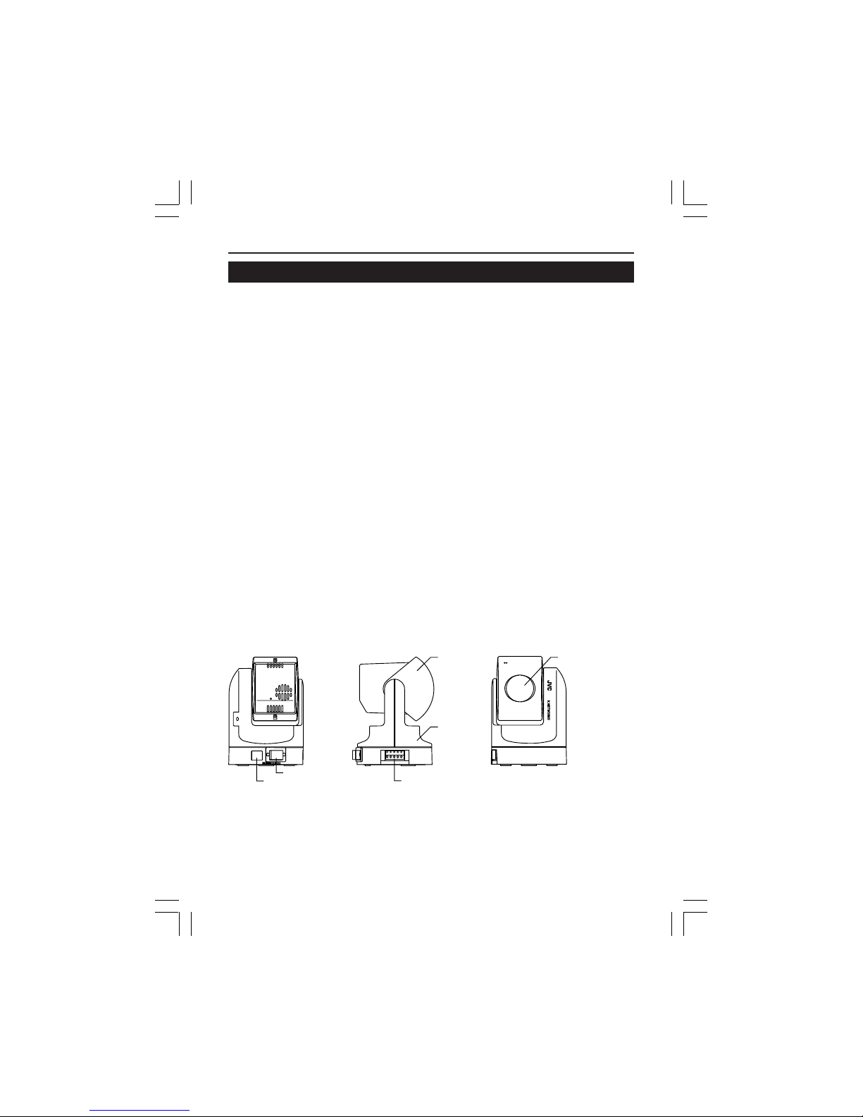
Names of VN-C3U parts
10BASE-T10BASE-T
DC12VDC12V
Rear view
DC IN jack
10BASE-T port
Body
Alarm IN/OUT jack
Side view
Front view
Lens coverLens unit
VM-C3UE.65J 00.4.7, 5:34 PM10
Page 10
11
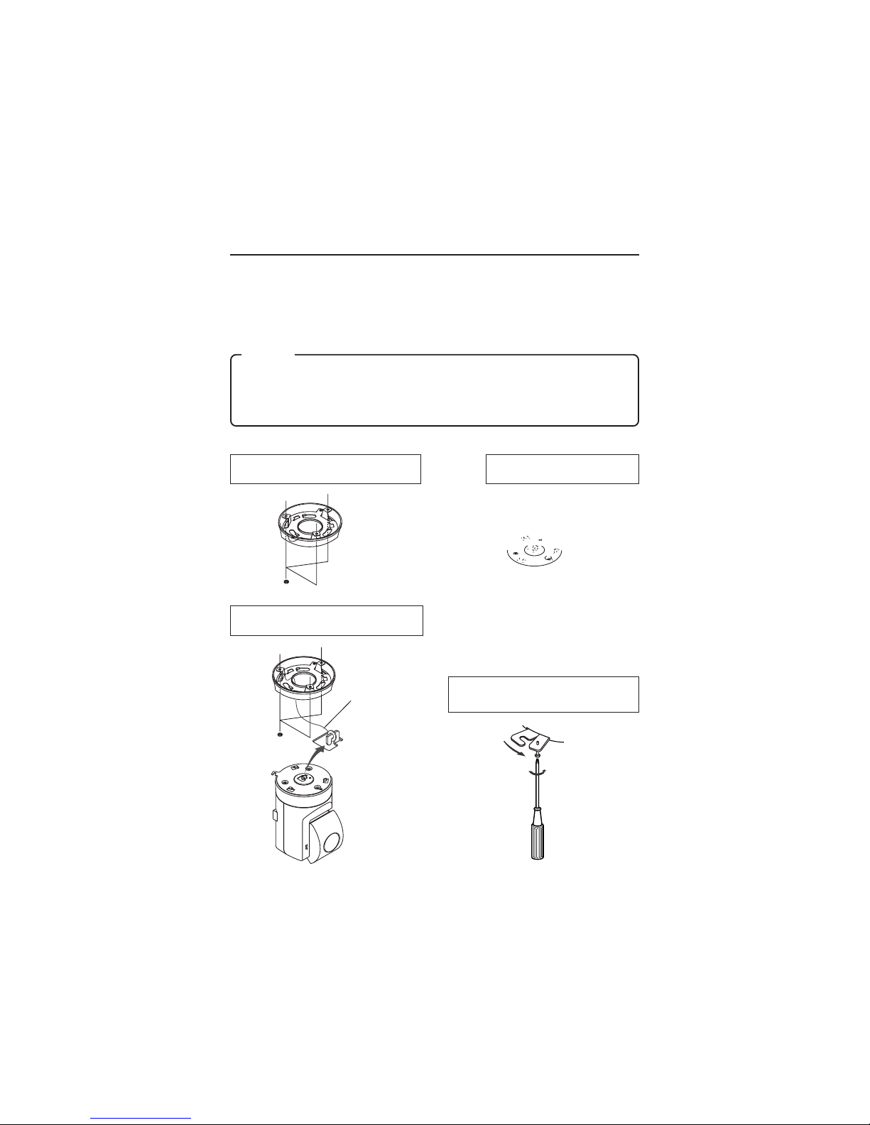
Installation and setup
1. Installation
Use the optional bracket (Model VN-BK30) for installation.
Make the power and network connections after completion of the installation work.
Caution
Install in a location with sufficient strength to prevent falling.
VN-C3U units can only be installed as shown in the diagram below, or
inverted. Do not install facing sideways.
Tilted installation is not possible.
1 Attach the ceiling fixer with the P hole
pointing toward the front of the camera.
4 Mount the VN-C3U on the ceiling fixer
by rotating clockwise, then tighten the
screw of the camera body fixer.
2 Mount the camera body fixer
on the VN-C3U.
3 Attach the drop-prevention wire of the
ceiling fixer to the camera body fixer.
drop-prevention wire
V.NETWORKS
Page 11
12
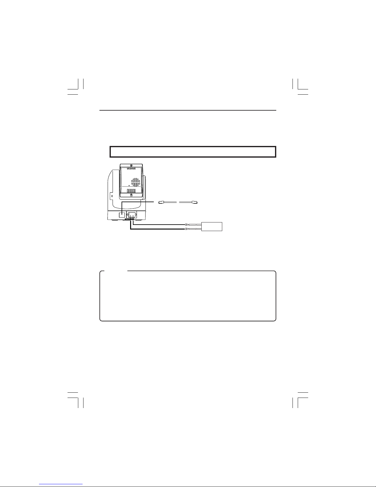
2. Connecting to a network
Turn on the power of only one VN-C3U unit.
When network connection is completed and the power is turned on, the
VN-C3U unit will be connected to the network at the following IP address.
Factory set (Default) IP address 192. 168. 0. 2
● About the power supply connection cable
• Length: 30m or less.
• Recommended model: UL1007, UL1015 or equivalent cable with wire
equivalent to ID AWG #20 or larger.
Caution
All VN-C3U units are set to the same IP address at the factory; therefore,
if the power of multiple VN-C3U units is turned on at the same time, address
duplication will occur and correct access will not be possible. Always turn
the power on for only one unit at a time. If address duplication occurred,
perform the proper processing and wait for 10 min. or more, or turn off the
power of all units on the network and then turn the power on again;
otherwise, correct access may not be possible.
10BASE-T
DC12V
–
+
10 BASE-T cable
12VDC
power supply
❉ Use a straight cable when
connecting to a hub.
Use a cross cable when
connecting directly to a PC.
Power supply connection cable
VM-C3UE.65J 00.4.7, 5:34 PM12
Page 12
13
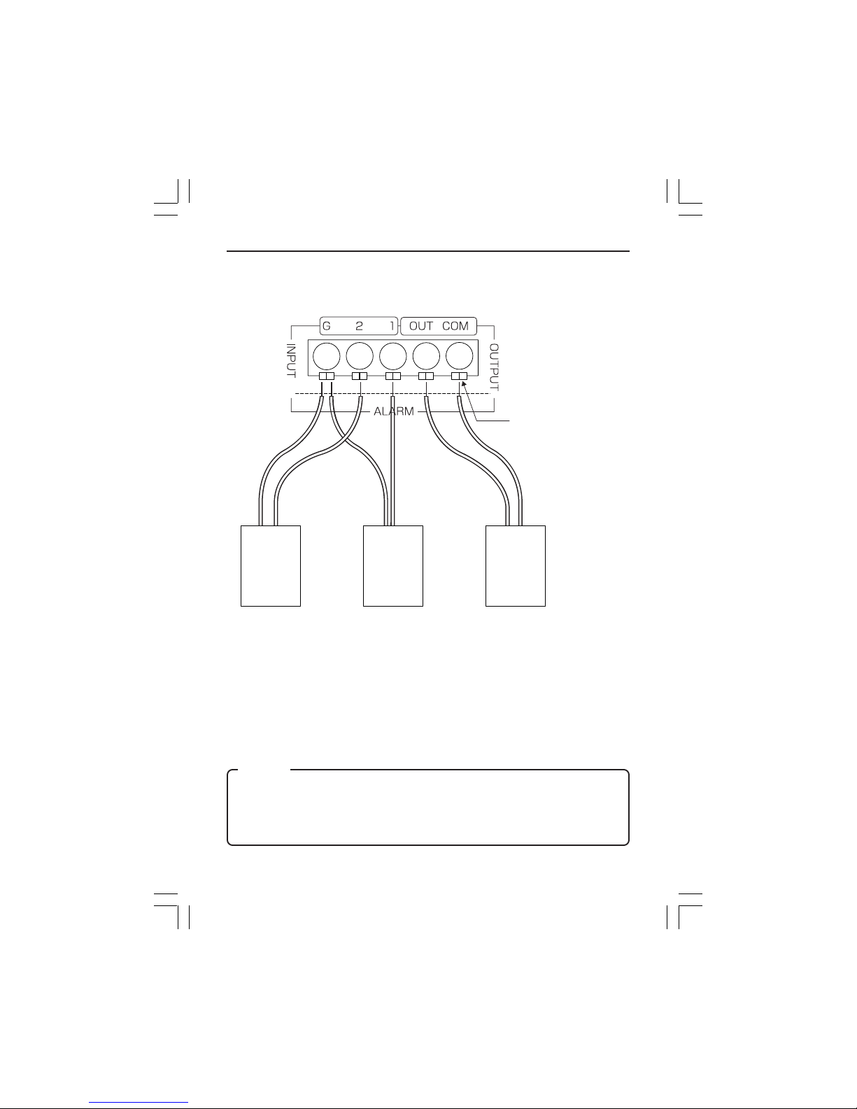
Alarm IN/OUT connection
Connect external devices to the alarm IN/OUT as shown below.
● Cable connection and disconnection
Press the sensor insert button when connecting and disconnecting cables.
After connecting or disconnecting, make sure the sensor insert button
returns to its original position.
● About the alarm IN/OUT connection cables
• Length: use cables with a length of 50m or less.
• Recommended model: UL1007, UL1015 or equivalent cable with wire
equivalent to AWG #22 - AWG #18.
Sensor insert button
External
device
OUT 1
External
device
OUT 2
External
device
IN
Caution
External noise may affect the alarm working properly even with a cable
length of 50m or less. In such cases, it is necessary to either change to the
use of shielded cable to prevent influence by noise or to change the wiring
route to avoid passing close to the source of the noise.
VM-C3UE.65J 00.4.7, 5:34 PM13
Page 13

14
3. Setting the VN-C3U IP address
3-1 Changing the IP address of the PC
Display the network settings panel by selecting Settings from the Start
button, then selecting Control Panel and Network, in that order.
1 Select the TCP/IP item, then click
on Properties.
2
Before making a change, always
make a note of the original IP
address.
Change the IP address to
192.168.0.3.
3 Click on OK and then
reboot the PC.
Set the subnet mask to a value
suitable for the setting operation. If
the value is unknown, check with the
network administrator.
VM-C3UE.65J 00.4.7, 5:34 PM14
Page 14
15
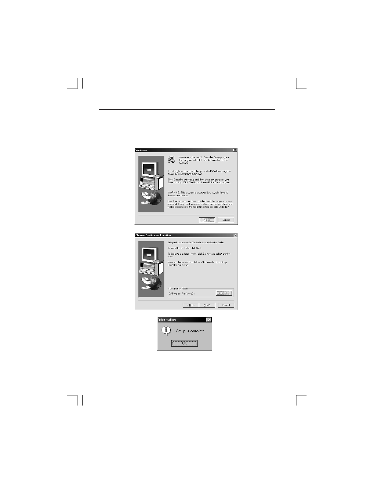
3-2 Installing the software
Load the VN-C3U Controller CD-ROM into the CD-ROM drive.
The setup program is in the ¥JVC folder on the CD-ROM.
Execute ¥JVC¥Setup.exe and follow the displayed instructions to setup
the software.
VM-C3UE.65J 00.4.7, 5:34 PM15
Page 15
16
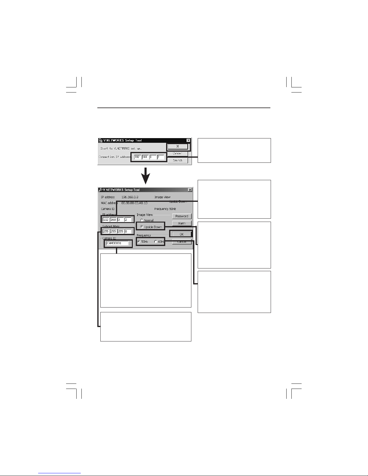
3-3 Setting the VN-C3U IP address
The V.NETWORKS setup tool is in the ¥Victor folder on the CD-ROM.
Execute ¥Victor¥setup¥vsetup.exe directly from the CD-ROM.
Enter the VN-C3U IP address.
Factory set (Default) IP
address 192. 168. 0.2
Change to an IP address
assigned or approved by the
network administrator.
(192.168.0.2 is used as an
example in the diagram.)
Specify normal installation
(with the lens unit of the VNC3U at the bottom of the body)
or inverted installation (with the
lens unit of the VN-C3U at the
top of the body), depending on
the installation conditions.
This setting reduces flicker
under fluorescent lighting.
Specify 50Hz or 60Hz in
accordance with the power
supply frequency used in the
installation area.
The camera ID corresponds to the
identification code located on the VNC3U body. Only alphanumerics can be
entered.
The user does not participate directly.
Normally, consecutive numbers such
as CAM00001, CAM00002..... will be
set.
Set the subnet mask to a value suitable
for the setting operation. If the value is
unknown, check with the network
manager.
❉ Refer to the next page for Password button and Page 20 for Alarm
button.
VM-C3UE.65J 00.4.7, 5:34 PM16
Page 16

17
Password function
An access protection using a password is provided to regulate connecting
PCs (users). Password setting and cancellation is performed by the
V.NETWORKS setup tool.
Caution
Never forget the current password because the current password setting
cannot be changed unless it matches the password setting.
The screen shown below will be displayed when the password button of the
V.NETWORKS setup tool is clicked.
Enter the current password. In
the case of new password
setting, nothing need be
entered.
The characters entered will be
indicated by asterisks (❉).
When setting a password or
changing the password, enter
the same password as above
and below.
Nothing need be entered when
password setting is being
cancelled.
The characters entered will be
indicated by asterisks (❉).
The change will occur
when Yes is clicked.
VM-C3UE.65J 00.4.7, 5:34 PM17
Page 17

18
Alarm function
This function is to receive or send an alarm signal from/to alarm input/
output over network. Use the V .NETWORKS setup tool for the fundamental
settings.
When the Alarm button of the V.NETWORKS setup tool is clicked, the
screen shown below will be displayed.
Caution
When VN-C2U or VN-C1U is controlled from VN-C3U controller, the alarm
setting is not available.
The procedure for the alarm settings is explained on the following page.
VM-C3UE.65J 00.4.7, 5:34 PM18
Page 18

19
The Alarm 1 and Alarm 2 settings
determine whether or not the
alarm function on Alarm 1 and
Alarm 2 are effective (ON or OFF).
When ON is selected, “Alarm
Output” (to send a signal to Alarm
out) and “Go to a preset position”
(one of the 10 preset positions) are
available.
When the Alarm 1 and Alarm 2
receive signals in sequence, use
the Relay Alarm Function to make
the different settings from the
above mentioned Alarm 1 and
Alarm 2 settings.
Place a check beside Use Relay
Alarm and specify the alarm
occurrence sequence and the time
interval.
VM-C3UE.65J 00.4.7, 5:34 PM19
Page 19

20
Out port setting includes the following settings:
OFF/ON: Determine whether or not an alarm is to be output.
Output value: Determine whether the High or Low signal will be output
when an alarm occurs. Enter the time for continuous signal output of
selected output value (High or Low) in the text box below.
Example: High 100ms
The High signal will be output for 100ms. After that, the output
value will change to Low.
Initialization: Determine whether or not the alarm signal will be output
one time when the power is turned on.
❉ Set the values of Out port setting in accordance with the device to which
the output is to be sent.
Retry: Determines the number of retries (1 - 3) to be made when alarm
input arrives.
Alarm force output: Press the Output button for compulsory alarm output
from the camera alarm Out port in accordance with the current alarm Out
port settings. This can be used for checking devices connected to the output
port.
VM-C3UE.65J 00.4.7, 5:34 PM20
Page 20

21
The list of alarm broadcast client (IP address and
port number) currently registered in the camera can
be displayed by pressing Client List. The PCs that
satisfy the following conditions are displayed.
• The VN-C3U controller has been started and is
connected to the VN-C3U subject to setup.
• Checks are placed at Settings and Alarm Reg.
PCs can be deleted from the
broadcast client list by selecting the
IP address and pressing Delete.
Return to Alarm Setting window by
pressing OK.
Caution
Once the PC is deleted from the Broadcast client list, the alarm does not
function.
VM-C3UE.65J 00.4.7, 5:34 PM21
Page 21

22
Caution
3-4 Restoring a work PC IP address
Using the same procedure as in 3-1, select Settings from the Start button, then select Control Panel and Network, Change to the original TCP/
IP properties setting that you made a note and then restore a work PC IP
address.
After restoration is completed, follow the messages of OS and reboot the
PC.
4. Enabling the IP address setting
Turn the VN-C3U power off and then on again. (When the power is turned
on, the pan/tilt reset operation will be performed; therefore, it is possible
to confirm that the power was turned on correctly by observing the pan/tilt
reset operation.)
❉ IP addresses changed with the setup tool become effective when the
VN-C3U power is turned off and then on again. (The previous IP address will remain effective until the power is turned off.)
Search function
The Search button is used to find the V .NETWORKS IP addresses currently
connected to the network.
When Search button is pressed, the Search screen will be displayed. When
Start Search button is pressed, a list of the V.NETWORKS IP addresses
currently connected to the network will be displayed. Timeout is used to set
the search time and can be set to 0 - 30 sec.
Caution When your own PC and a V.NETWORKS of a different
subnet are connected on a LAN, connection will not be possible even
if the search is successful.
In such cases, change to an appropriate IP address on your PC and
then try connection.
The V.NETWORKS setup tool can only be run on PCs which Setup.exe
was executed on page 17. The V.NETWORKS setup tool does not function
properly with PCs which Setup.exe has not been executed. With PCs which
Setup.exe has been executed, operation is possible from not only the CDROM but also the hard disk, etc. where the setup folder is copied.
The V.NETWORKS setup tool is software that is necessary only for the
setup operation; therefore, this software should be deleted at the end of
the operation, except for PCs which may require this software for special
reasons.
When setting two or more units, reboot the PC and then return to item 2
“Connecting to a network” (page 14). When all VN-C3U setting have been
completed, proceed to the following item.
VM-C3UE.65J 00.4.7, 5:34 PM22
Page 22

23
5. Registering connection points
Start the VN-C3U controller (VN-C3U.exe). Select New from the File item
in the menu and then specify the connection point.
Enter the IP address and name of the
VN-C3U connection point.
(192.168.0.2. is used as an example
in the diagram.)
The folder "VN-C3U Name" will be
created automatically in the folder
specified here. Recorded files will be
saved here. (Refer to page 43
concerning recording.)
"Upon the connection" determines
whether or not recording will start
automatically upon the connection of
VN-C3U.
If the settings are completed, press
OK to end registration of connection
point.
Advice
Copying registered connection points to another PC, VN-C3U connection
points data is saved to a file with the .dat extension inside the folder created
by VN-C3U controller.
All the connection points settings can easily be copied to another PC by
copying the file with the .dat extension.
VM-C3UE.65J 00.4.7, 5:34 PM23
Page 23

24
Controller Software Operation
Starting connection and changing connection points
Refer to Software Installation on page 17 for the installation procedure.
When the VN-C3U controller (VN-C3U.exe) is executed, a logo will be
displayed and then the following screen will appear.
Connection points can be selected from this
pulldown menu.
VM-C3UE.65J 00.4.7, 5:35 PM24
Page 24

25
Connecting from the Settings file
Connection is possible by linking the VN-C3U.exe and vnet*.data files and
then double clicking the *.dat file.
Preparation
1. Start Explorer, then click on Folder Options... from the View menu.
2. Click on New type... of the File Types tab. Enter an explanation in the
Description of type box.
Example: Dat file.
3. Enter ".dat" in the Associated Extensions box. Click on New... and then
enter "open" in the Action box.
4. Specify "VN-C3U.exe" in the Application used to perform action box.
Example: C:¥Program Files¥VN-C3U¥VN-C3U.exe
Caution
• This function cannot be used if the ".dat" extension has already been
specified as the file type for another application.
VM-C3UE.65J 00.4.7, 5:35 PM25
Page 25

26
Controller 1
After a connection point is selected, you will find the names of currently
connected VN-C3U, the pan/tilt operation angle step and the current Pan/Tilt
position.
Pan/Tilt operation
angle step
Current Pan/Tilt
position
Names of currently
connected
VN-C3U
Pan/tilt, Zoom-in/
Zoom-out
operation buttons
The Pan/Tilt operation angle step of connected VN-C3U can be changed by
clicking on the left and right (
) buttons.
Pan/Tilt position can be changed with the Pan/T ilt operation buttons (8 buttons).
Zoom in/Zoom out is performed by one step for each click of zoom button. If
you keep pressing the button, Zoom in/Zoom out can be performed
continuously.
Pan range
Tilt range
320°
90°
VM-C3UE.65J 00.4.7, 5:35 PM26
Page 26

27
On-screen Pan/Tilt Function
Without using Pan/Tilt operation buttons, Pan/T ilt is manageable by doubleclicking on screen. The double-clicking point becomes around the center
or screen.
Caution
It is not possible to move
beyond the Pan/Tilt limits but
this is not a malfunction.
Caution
During the Pan/Tilt operation, the images may pause for a few seconds.
This is because the position correction function is automatically being
operated and this is not a malfunction.
VM-C3UE.65J 00.4.7, 5:35 PM27
Page 27

28
Controller 2
The VN-C3U controller has the
position memory function (up to
10 positions). By pressing this
button, the current position is
changed to the already
memorized position.
Refer to "Changing position
memory" on page 37
concerning changing the
contents of the position
memory.
The VN-C3U controller has
the Snapshot function. This
function allows you to
capture still images or save
them onto the hard disk.
For details, refer to
"Snapshot function" on page
46.
The size of VN-C3U controller can
be smaller by pressing this button.
It is possible to switch between the
normal and smaller controller.
Smaller Controller
Name of connected
VN-C3U
Memorized position
display
Pan/tilt operation
buttons
Connection point selection
(pulldown menu)
Position memory
change button
Caution
During the position memory operation, the images may pause for a few
seconds. This is because the position correction function is automatically
being operated and there is not a malfunction.
Button to return to
the normal size
controller
VM-C3UE.65J 00.4.7, 5:35 PM28
Page 28

29
Controller 3
The VN-C3U controller has
the record and playback
function.
For details, refer to "Record
and playback function" on
page 43.
Pan/Tilt operation angle step can
be set by clicking the value and
directly enter any value. After
entering (changing) the value,
press the Enter key.
If the cursor is briefly positioned over the VNC3U name, a balloon display of VN-C3U
names will be displayed.
Creating new connection points
Refer to "Registering connection points" on page 25.
VM-C3UE.65J 00.4.7, 5:35 PM29
Page 29

30
Deleting connection points
Select File from the menu and
then select Delete.
Select a connection
point to be deleted
and then click on OK.
Make sure the desired point is
being deleted, and then press
OK.
Caution
The connection point cannot be recovered once it is deleted.
VM-C3UE.65J 00.4.7, 5:35 PM30
Page 30

31
Changing resolution and inverting the image
Select View from the menu.
The resolution can now be
selected from 160 × 120, 320 ×
240 or 640 × 480. Depending on
the installation, select Normal or
Upside Down.
On-screen resolution change
The resolution can also be changed on the screen with the
following procedure.
Click the right button of the
mouse on the screen and select
one of the following: 160 x 120,
320 x 240 or 640 x 480.
VM-C3UE.65J 00.4.7, 5:35 PM31
Page 31

32
Image quality adjustment
Select Settings from the menu and
then select Quality.
The compression rate is in
inverse proportion to the
image quality. The frame rate
is in direct proportion to the
compression rate.
Compression rate
Low — Medium — High
Image quality
High — Medium — Low
Frame rate
Low — Medium—High
This is set to the factory
(default) value.
Click on OK to validate a
setting change.
❉ Refer to the following pages for details concerning image quality settings.
VM-C3UE.65J 00.4.7, 5:35 PM32
Page 32

33
Image quality settings
Image quality can be adjusted by changing each of the following settings.
Item
Effect
Saturation
Adjustment of the color saturation.
(The larger the number, the greater the color
saturation.)
Color balance
Move the slide bar to the right to emphasize blue
or to the left to emphasize red.
Full Auto
This the Auto/Manual switch. (When the check is
removed, the following three items will be switched
to the Manual setting.
Gain
Adjustment of the gain of the internal amp. (Use
only when light is insufficient.)
Contrast
Adjustment of the contrast.
Brightness Adjustment of the brightness.
VM-C3UE.65J 00.4.7, 5:35 PM33
Page 33

34
Transmission frames
Select Settings from the menu
and then select Frame Rate.
This is to set the upper limit or
frame rate transmitted from VNC3U.
Caution
The actual frame rate depends on the operational environment (PC, LAN,
phone line, etc.) and may be different from the transmission frame rate. In
practice, the higher transmission frame rate is set up, the more bandwidth
is required. Therefore, try to set the lower transmission frame rate if relatively
low bandwidth is available for VN-C3U.
VM-C3UE.65J 00.4.7, 5:35 PM34
Page 34

35
12
3
Changing position memory
Select Setting from the menu and then
select Position Memory.
Procedure for Position
memory change
1 Use the position memory
buttons, Pan/Tilt/Zoom
setting and lens setting to
set the status in position
memory.
2 Press one of these memory
buttons in which the status
set in step 1is to be
memorized.
3 Press OK to close the
position memory setting
window.
Caution
• When VN-C2U or VN-C1U is controlled from VN-C3U controller , the Lens
Setting is not available.
• The position memory 1-6 is available for VN-C2U. (VN-C1U uses a fixed
type lens)
• When the zoom scroll bar is set to the Tele end, the lens position may
not be the same after changing its position.
VM-C3UE.65J 00.4.7, 5:35 PM35
Page 35

36
Lens setting
Select Setting from the menu and then select
Lens settings.
The current setting status is
displayed in the window.
After the setting is completed,
press OK to close this window.
Caution
This function is not available for VN-C1U and
VN-C2U.
• When the iris is set to Auto, the amount of light entering the camera will
be kept constant. When Manual is selected, the brightness of the screen
will be kept constant. The scroll bar is used to perform the respective
settings.
• When Auto is selected from Focus, the scroll bar will become inoperative.
Operation of the scroll bar is possible when Manual is selected.
Advice
For locations where many people are passing by or operation of zoom at
Tele, we recommend select Manual Focus to prevent continuous auto
focusing.
VM-C3UE.65J 00.4.7, 5:35 PM36
Page 36

37
Alarm setting
The alarm settings determines the actions to be performed when an alarm
signal is received from Alarm 1 or Alarm 2 input of VN-C3U. Make sure to
select "ON" in Alarm 1/Alarm 2 setting of V.NETWORKS setup tool (refer to
page 21) to enable all the Alarm settings in this page.
Select Settings from the menu, then
select Alarm Settings.
There are four functions as follows:
• Message Pop-up
Pop-up the message entered in the text box. Up to 100 letters can be
entered.
• Recording start
Start recording the images.
• Play a wave file
Play a specified wave file . Any wave files can be specified from the
Browse button.
• Execute a program file
Execute a specified program file. Any execute (.exe) files can be specified
from the Browse button.
VM-C3UE.65J 00.4.7, 5:35 PM37
Page 37

38
To enable the Alarm 1, Alarm 2 and/or
Relay Alarm settings, it is necessary
to check (✔) Alarm reg.
Relay alarm setting
The Relay Alarm Setting determines the actions to be performed when an
alarm signal is received from Alarm 1
and Alarm 2 input of VN-C3U. There
are two functions; Play a wave file and execute a program file. (Refer to
page 39) Make sure to select "ON" in Relay Alarm Setting of V.NETWORKS
setup tool (refer to page 21) to enable these Relay Alarm setting in this
page.
Caution
• When a large wave file (*.wav) is selected, the alarm operation may be
delayed depending on the PC specifications. Try to select a relatively
small wave file.
• In order to enable the Alarm 1, Alarm 2 and/or Relay Alarm setting it is
necessary to
1) Select "ON" in Alarm 1, Alarm 2 and/or Relay Alarm setting of
V.NETWORKS setup tool (refer to page 21),
and
2) Check (✔) Alarm reg.
• When relay alarm has been set, the second alarm operations is not
performed.
Example: When the Relay Alarm occurs in the sequence of
Alarm 1→ Alarm 2, alarms operate in the sequence of
Alarm 1→ Relay Alarm and Alarm 2 does not operate at all.
VM-C3UE.65J 00.4.7, 5:35 PM38
Page 38

39
Select Setting from the menu and then
select Time Stamp.
Time stamp setting
This setting determines whether or not
the time stamp is displayed on the
screen.
The color of text and background are
adjustable. Select transparency if the
background is not necessary.
The size of font in preview window
does not change.
❉ Changing the time stamp display position
On the screen, hold down the Shift key and click the left button of the
mouse at the position where time stamp is to be displayed.
VM-C3UE.65J 00.4.7, 5:35 PM39
Page 39

40
Any of the following 7 display styles can be selected.
YYYY/MM/DD HH:MM:SS.mm
(year/month/date hour: minute: second. millisecond)
YYYY/MM/DD HH:MM:SS
(year/month/date hour: minute: second)
DD/MM/YYYY HH:MM:SS
(date/month/year hour: minute: second)
MM/DD/YYYY HH:MM:SS
(month/date/year hour: minute: second)
MM/DD HH:MM:SS
(month/date hour: minute: second)
HH:MM:SS
(hour: minute: second)
HH:MM
(hour:minute)
VM-C3UE.65J 00.4.7, 5:35 PM40
Page 40

41
Recording function
This function is to continuously record the images of connected VN-C3U onto
automatically created folder with "VN-C3U Name." (refer to page 25)
Press the "REC" button.
"REC" appears in the upper right
corner on the screen and recording
starts.
Press the Stop button to stop
recording. “REC” disappear.
❉ Never change the saved files and their name, otherwise all the saved
images may not be correctly playback.
VM-C3UE.65J 00.4.7, 5:35 PM41
Page 41

42
Playback function
Press the Play button.
When connecting VN-C3U, press
Yes to quit current connection and
start playback. This message
does not appear if no VN-C3U is
connected.
Select the folder where the
recorded images have been
saved.
The recorded time is indicated in the unit of one minute.
Select the time for playback and press OK.
VM-C3UE.65J 00.4.7, 5:35 PM42
Page 42

43
Indicate which file is being
play back.
Press PLAY to start playback. Once playback is started,
this button is changed to PAUSE.
Press STOP to stop playback.
Double-click to return to the playback time selection
window.
VM-C3UE.65J 00.4.7, 5:35 PM43
Page 43

44
Press Snapshot button.
Caution
• Saved images can be displayed with ordinary viewer software. However ,
inverted images cannot be displayed inverted. Colors may also differ
from those seen on the VN-C3U controller screen.
• Do not start other image viewing application while the VN-C3U Controller
Software is active. This is particularly important with Windows 95 as it
may cause a failure in saving snapshots. In this case, use the recording
function to save images.
Snapshot function
This function is to capture still images or save them onto hard disk.
Up to 16 images can be captured. After the 16th
image is captured, snapshot button disappears.
Select Save As on the
captured image to opened
Save AS window.
Specify the location.
Enter the file name.
Press Save to save the file.
VM-C3UE.65J 00.4.7, 5:35 PM44
Page 44

45
Click the right button of the mouse
on the screen and select Property.
V.NETWORKS property
Display the property of connected VN-C3U.
MAC address
The MAC address of connected VN-C3U.
IP Address
The IP address of connected VN-C3U.
V.NETWORKS type
The camera model (VN-C1U, VN-C2U or VN-C3U)
Program version
The version of VN-C3U unit.
Save in
The location where recorded images are to be saved.
VM-C3UE.65J 00.4.7, 5:35 PM45
Page 45

46
Troubleshooting
An IP address changed
with the V.NETWORKS
setup tool has been
forgotten.
The Search button of the V.NETWORKS
setup tool can be used to acquire the IP
addresses of V.NETWORKS cameras
connected to the network.
The change history file vsetup in the root
directory is used to save contents that have
been changed with the V.NETWORKS setup
tool in the following formats.
IP before change, ID before change
IP after change, ID after change
Date/time (date/month/year/hour/minute)
If the desired information cannot be found by
viewing the vsetup file, this must be handled
as a repair. Please consult your local dealer.
Recording is not
possible.
• It is possible to delete the folder used to
save images. Check to make sure the folder
exists.
• It is possible for the disk to become full.
Check the available capacity of the disk.
The password set with
the password protection
function has been
forgotten.
The disabling of the password protection
function is handled as a repair. Please consult
your local dealer.
For safety, be prepared to show proper
identification.
The message "Pan/tilt
control is not being
performed correctly." is
displayed at the time of
connection.
Turn off the VN-C3U power and then turn it
on again. If there is no improvement, please
consult your local dealer.
Time is required for
cancellation when
"Connecting..." is
displayed.
Once the connection operation starts,
cancellation is not possible for a period of
several seconds.
VM-C3UE.65J 00.4.7, 5:35 PM46
Page 46

47
The colors are not
satisfactory.
• Check the color adjustments of the display
or video card.
The colors displayed by different PC display
monitors and video cards will differ to some
degree. Improvement is sometime possible
by adjusting the color settings of the display
monitor. Depending on the video card,
colors can sometimes be adjusted using
Screen Properties (click the right mouse
button on the desktop.)
• Switching to True Color (24-bit) display
Colors are sometimes not natural at the
High Color (16-bit) or lower setting. It is
recommended that you use True Color.
• Adjusting color balance
Colors can also be changed by using Color
Balance from the image quality adjustment
screen.
• Turn Auto off and then on again.
When different light sources have been
used.
(For example, when alternately using
sunlight outdoors and fluorescent lighting
indoors.)
Time is sometimes required for auto
tracking white balance to start operating.
In such cases, white balance can
sometimes be made to work quickly by
removing the check from Auto in the image
quality adjustment screen and then
replacing the check.
• Depending on the subject, the colors may
appear to vary slightly in some cases. This
is not a malfunction.
The image size and
position change
spontaneously.
When one VN-C3U unit is connected to
several PCs, the last PC to operate and set
the VN-C3U unit will have priority.
VM-C3UE.65J 00.4.7, 5:35 PM47
Page 47

48
Out of focus. The autofocus sometimes does not operate
correctly in dark places and when blank
surfaces such as walls are photographed. In
such cases, focus manually.
The focus may be off slightly when manual
focus is used at the TELE position, but this is
not a malfunction.
VN-C3U connection is
not possible or the
connection has been
broken.
When there are multiple occurrences of
broadcasts, collisions, etc., or when the
network status is not normal, it may become
impossible to connect the VN-C3U or the
connection may be broken.
VM-C3UE.65J 00.4.7, 5:35 PM48
Page 48

49
10BASE-T
Specifications
LAN standard IEEE 802.3
Communication protocol UDP/IP
Video element 1/3-inch, 300,000-pixel CMOS image sensor.
Minimum focusing distance 1.0m
Pan/tilt operation angle Pan: 320
°
Tilt: 90 °
Output image format 640 × 480, 320 × 240, 160 ×120
Power supply voltage DC 12 V
Power consumption 2.0 A (max.)
Operating temperature 0° C — 40° C
Mass (weight) Approx. 730 g.
Alarm input Non-voltage a contact input
Low level. latch/momentary (500ms or more)
Low level circuit current 1mA
High level impressed voltage 5V
Alarm output NPN open collector output (allowable impressed
voltage: 12V; allowable input current: 300mA)
External dimensions (Unit: mm)
VM-C3UE.65J 00.4.7, 5:35 PM49
Page 49

VICTOR COMPANY OF JAPAN, LIMITED
is a registered trademark owned by VICTOR COMPANY OF JAPAN, LTD.
is a registered trademark in Japan, the U.S.A., the U.K. and many other countries.
Printed in Japan
SS961510-001
VM-C3UE.65J 00.4.7, 5:35 PM50
Page 50

VN-C3U
INSTRUCTIONS
V.NETWORKS
For Customer Use:
Enter below the Serial No. which is
located on the body. Retain this
information for future reference.
Model No. VN-C3U
Serial No.
This instruction book is made from 100%
recycled paper.
SS961510-001
VM-C3UE.65J 00.4.7, 5:35 PM51
 Loading...