

Page 1
V.NETWORKS
VN-C2U
INSTRUCTIONS
Thank you for purchasing the JVC VN-C1U.
To gain maximum benefit from this product, read this
instruction manual carefully before use and retain it for future
reference.
The serial number is very important for maintaining quality of
your product. At the time of purchase, check to see that the
serial number is correctly printed on the top of the unit and
that the serial numbers on the unit and warranty match.
This instruction manual is printed on
recycled paper.
For Customer Use:
Enter below the Model No. and Serial
No. which are located on the rear of the
cabinet. Retain this information for future
reference.
Model No.
Serial No.
SS961423-002
Page 2
IMPORTANT SAFEGUARDS
1. Read all of these instructions.
2. Save these instructions for later use.
3. All warnings on the product and in the operating instructions should
be adhered to.
4. Unplug this appliance system from the wall outlet before cleaning.
Do not use liquid cleaners or aerosol cleaners. Use a damp cloth
for cleaning.
5. Do not use attachments not recommended by the appliance manufacturer as they may cause hazards.
6. Do not use this appliance near water – for example, near a bathtub, washbowl, kitchen sink, or laundry tub, in a wet basement, or
near a swimming pool, etc.
7. Do not place this appliance on an unstable
cart, stand, or table. The appliance may fall,
causing serious injury to a child or adult, and
serious damage to the appliance.
Use only with a cart or stand recommended
by the manufacturer, or sold with the appliance. Wall or shelf mounting should follow
the manufacturer's instructions, and should
use a mounting kit approved by the manufacturer.
An appliance and cart combination should be moved with care.
Quick stops, excessive force, and uneven surfaces may cause the
appliance and cart combination to overturn.
8. Slots and openings in the cabinet and the back or bottom are provided for ventilation, and to insure reliable operation of the appliance and to protect it from overheating, these openings must not
be blocked or covered. The openings should never be blocked by
placing the appliance on a bed, sofa, rug, or other similar surface.
This appliance should never be placed near or over a radiator or
heat register. This appliance should not be placed in a built-in installation such as a bookcase unless proper ventilation is provided.
9. This appliance should be operated only from the type of power
source indicated on the marking label. If you are not sure of the
type of power supplied to your home, consult your dealer or local
power company. For appliance designed to operate from battery
power, refer to the operating instructions.
10. This appliance system is equipped with a 3-wire grounding type
plug (a plug having a third (grounding) pin). This plug will only fit
into a grounding-type power outlet. This is a safety feature. If you
are unable to insert the plug into the outlet, contact your electrician to replace your obsolete outlet. Do not defeat the safety purpose of the grounding plug.
PORTABLE CART WARNING
(symbol provided by RETAC)
S3126A
Page 3

11. For added protection for this product during a lightning storm, or
when it is left unattended and unused for long periods of time,
unplug it form the wall outlet and disconnect the antenna or cable
system. This will prevent damage to the product due to lightning
and power-line surges.
12. Do not allow anything to rest on the power cord. Do not locate this
appliance where the cord will be abused by persons walking on it.
13. Follow all warnings and instructions marked on the appliance.
14. Do not overload wall outlets and extension cords as this can result
in fire or electric shock.
15. Never push objects of any kind into this appliance through cabinet
slots as they may touch dangerous voltage points or short out parts
that could result in a fire or electric shock. Never spill liquid of any
kind on the appliance.
16. Do not attempt to service this appliance yourself as opening or
removing covers may expose you to dangerous voltage or other
hazards. Refer all servicing to qualified service personnel.
17. Unplug this appliance from the wall outlet and refer servicing to
qualified service personnel under the following conditions:
a. When the power cord or plug is damaged or frayed.
b. If liquid has been spilled into the appliance.
c. If the appliance has been exposed to rain or water.
d. If the appliance does not operate normally by following the op-
erating instructions. Adjust only those controls that are covered
by the operating instructions as improper adjustment of other
controls may result in damage and will often require extensive
work by a qualified technician to restore the appliance to normal operation.
e. If the appliance has been dropped or the cabinet has been dam-
aged.
f. When the appliance exhibits a distinct change in performance –
this indicates a need for service.
18. When replacement parts are required, be sure the service technician has used replacement parts specified by the manufacturer that
have the same characteristics as the original part. Unauthorized
substitutions may result in fire, electric shock, or other hazards.
19. Upon completion of any service or repairs to this appliance, ask
the service technician to perform routine safety checks to determine that the appliance is in safe operating condition.
VICTOR COMPANY OF JAPAN, LIMITED
Printed in Japan
Page 4

IMPORTANT SAFEGUARDS
1. Read all of these instructions.
2. Save these instructions for later use.
3. All warnings on the product and in the operating instructions should
be adhered to.
4. Unplug this appliance system from the wall outlet before cleaning.
Do not use liquid cleaners or aerosol cleaners. Use a damp cloth
for cleaning.
5. Do not use attachments not recommended by the appliance manufacturer as they may cause hazards.
6. Do not use this appliance near water – for example, near a bathtub, washbowl, kitchen sink, or laundry tub, in a wet basement, or
near a swimming pool, etc.
7. Do not place this appliance on an unstable
cart, stand, or table. The appliance may fall,
causing serious injury to a child or adult, and
serious damage to the appliance.
Use only with a cart or stand recommended
by the manufacturer, or sold with the appliance. Wall or shelf mounting should follow
the manufacturer's instructions, and should
use a mounting kit approved by the manufacturer.
An appliance and cart combination should be moved with care.
Quick stops, excessive force, and uneven surfaces may cause the
appliance and cart combination to overturn.
8. Slots and openings in the cabinet and the back or bottom are provided for ventilation, and to insure reliable operation of the appliance and to protect it from overheating, these openings must not
be blocked or covered. The openings should never be blocked by
placing the appliance on a bed, sofa, rug, or other similar surface.
This appliance should never be placed near or over a radiator or
heat register. This appliance should not be placed in a built-in installation such as a bookcase unless proper ventilation is provided.
9. This appliance should be operated only from the type of power
source indicated on the marking label. If you are not sure of the
type of power supplied to your home, consult your dealer or local
power company. For appliance designed to operate from battery
power, refer to the operating instructions.
10. This appliance system is equipped with a 3-wire grounding type
plug (a plug having a third (grounding) pin). This plug will only fit
into a grounding-type power outlet. This is a safety feature. If you
are unable to insert the plug into the outlet, contact your electrician to replace your obsolete outlet. Do not defeat the safety purpose of the grounding plug.
PORTABLE CART WARNING
(symbol provided by RETAC)
S3126A
Page 5

11. For added protection for this product during a lightning storm, or
when it is left unattended and unused for long periods of time,
unplug it form the wall outlet and disconnect the antenna or cable
system. This will prevent damage to the product due to lightning
and power-line surges.
12. Do not allow anything to rest on the power cord. Do not locate this
appliance where the cord will be abused by persons walking on it.
13. Follow all warnings and instructions marked on the appliance.
14. Do not overload wall outlets and extension cords as this can result
in fire or electric shock.
15. Never push objects of any kind into this appliance through cabinet
slots as they may touch dangerous voltage points or short out parts
that could result in a fire or electric shock. Never spill liquid of any
kind on the appliance.
16. Do not attempt to service this appliance yourself as opening or
removing covers may expose you to dangerous voltage or other
hazards. Refer all servicing to qualified service personnel.
17. Unplug this appliance from the wall outlet and refer servicing to
qualified service personnel under the following conditions:
a. When the power cord or plug is damaged or frayed.
b. If liquid has been spilled into the appliance.
c. If the appliance has been exposed to rain or water.
d. If the appliance does not operate normally by following the op-
erating instructions. Adjust only those controls that are covered
by the operating instructions as improper adjustment of other
controls may result in damage and will often require extensive
work by a qualified technician to restore the appliance to normal operation.
e. If the appliance has been dropped or the cabinet has been dam-
aged.
f. When the appliance exhibits a distinct change in performance –
this indicates a need for service.
18. When replacement parts are required, be sure the service technician has used replacement parts specified by the manufacturer that
have the same characteristics as the original part. Unauthorized
substitutions may result in fire, electric shock, or other hazards.
19. Upon completion of any service or repairs to this appliance, ask
the service technician to perform routine safety checks to determine that the appliance is in safe operating condition.
VICTOR COMPANY OF JAPAN, LIMITED
Printed in Japan
Page 6

Package Contents
This product is packaged with the following items. Contact your dealer of purchase for any missing
items.
VN-C2U main unit
VN-C2U controller CD-ROM
Ferrite core
Instruction manual (this document)
Operational Environment
The following environment is necessary for the operation of VN-C2U.
PC operating with Microsoft Windows 95,98 or NT
CPU : Pentium 133MHz or equivalent or higher
Memory : 32MB or more (64MB or more recommended)
Hard disk space : 20MB or more
Display and video card : 640 X 480 pixels or higher; high color
10BASE-T : LAN board, connector cables
(200MHz or higher recommended)
(1024 X 768 pixels or higher; true color recommended)
LAN environment
10BASE-T network cross-connected with HUB, etc. of IEEE802.3 standard.
It is also possible to connect your PC with VN-C2U directly (1:1) using a crossing cable
(please check since some LAN boards do not allow use of cross cables).
1
Page 7

Precautionary Notes
Avoid installing in the following locations:
• Where the unit is exposed to rain or water
• Where the ambient temperature exceeds the range of 0∞C ~ +40∞C (recommended)
• Where there is vibration
• Dusty areas or areas with oil or gas
The sensitivity will automatically increase when using this unit in a dark location with the
AGC on (Full Auto on). At this time the ??screen may appear rough??; however this is not a
malfunction.
When using Full Auto on for the white balance of this unit, the tint may appear slightly
different from that of the actual color due to the principle of the automatic white balance
tracking circuit; however, this is not a malfunction.
When shooting a highly bright object such as lamps, etc. white tails may appear above and
below the object on the screen. This is an elemental characteristic seen when shooting solid
objects referred to as the smearing effect, and is not a malfunction.
About Upgrades
Upgrades of the software (VN-C2U) can obtained via the Internet. The upgrade software can be
downloaded from the following homepage:
http://www.jvc-victor.co.jp
2
Page 8
Installation and Setup
Before starting installation and setup
Since a setup of one IP address is necessary for each VN-C2U, follow the procedure given below to
setup each unit (the installation can be made at the same time if the power is left off.
1. Install VN-C2U
When installing in a location where it is difficult to turn the power on and off, install after
completing steps 2 through 5.
2. Connect VN-C2U to a network
(turn the power of VN-C2U on)
3. Set the IP address of VN-C2U
Always contact the network management for the IP address of VN-C2U and use only that which
is assigned or authorized.For setup of a second unit and following, reboot the PC and return to
step 2.
4. Enable the set IP address of VN-C2U
(Turn the power of VN-C2U off once, then turn the power back on)
5. Register the connecting point
Register the IP address information of VN-C2U to the user PC.
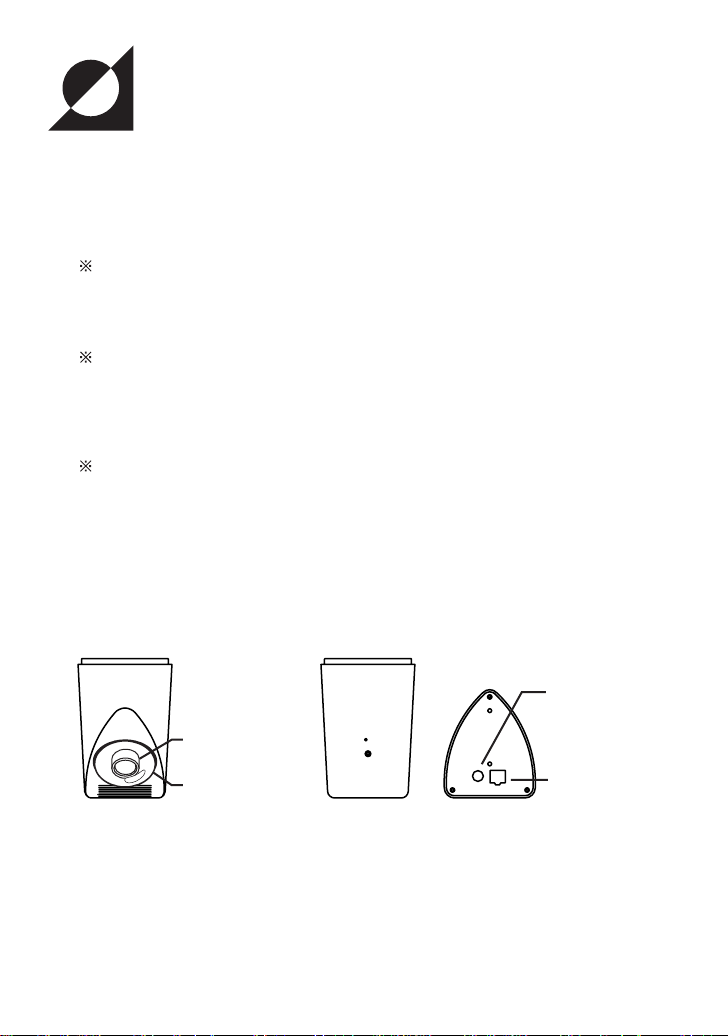
Names of VN-C2U parts
DC input jack
Lens block
Lens cover
10BASE-T port
Front Rear Top
3
Page 9
Installation and Setup
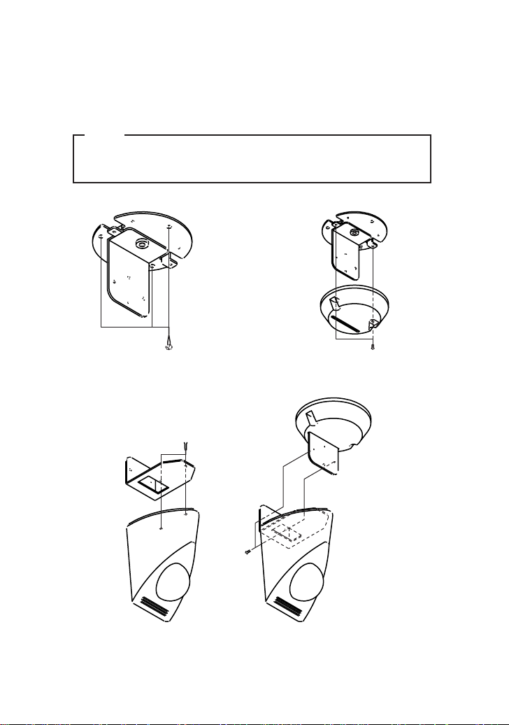
1. Installation
Install using the separately sold mounting kit (model no. VN-BK20).
Do not turn the power on or connect to a network until installation is completed.
Note
To prevent the unit from falling, mount only on areas with sufficient strength.
VN-C2U can be installed as shown in the diagram below, or inverted. Do not
install the unit sideways.
(1) Mount the bracket onto the ceiling, etc.
(3) Mount VN-C2U on the bracket
(2) Mount the cover on the bracket
4
Page 10

2. Connecting to a network
Turn on the power of only one VN-C2U.
Connecting VN-C2U to a network and turning on the power will connect the unit to a network with the
following IP address.
Factory set IP address : 192.168. 1. 2
To retain electromagnetic compatibillity,use the provided
ferrite core when connecting to VN-C2U.
Wound 3x
Special adapter
Install the ferrite core within 50mm
of VN-C2U-side connector.
Shielded
modular cable
When connecting to a HUB, use a straight cable.
When connecting directly to a PC, use a crossing cable.
Note
All VN-C2U at the time of shipment have the same IP address. Correct
access cannot be obtained when turning the power of multiple units on at the
same time due to overlap of ID addresses. Always turn on the power of one
unit at a time and proceed with the following VN-C2U IP address setup.
In the case where doubling of IP addresses occur, correct access may not be
achieved unless waiting for at least 10 minutes after making correction, or
turning off all network devices then turning them back on.
To power outlet
Ferrite core
5
Page 11

3. VN-C2U IP address setup
3-1 Changing the IP address of the PC making the setting
From the [Start] button proceed to [Setup] - [Control Panel] - [Network] to display the network
setup panel.
(1) Select TCP/IP and click Properties.
(2) Before making changes, take note
of the original IP address.
After taking note of the IP address,
change it to:192.168. 1. 1
(4) After clicking OK, reboot the PC.
(3) Set appropriate values for the Sub-
net Mask during the setting. If
unknown, contact your network
management.
6
Page 12

3-2 Installing the software
Insert the VN-C2U controller CD-ROM into the CD-ROM drive.
The setup program is located in the \JVC folder of the CD-ROM.
Execute \JVC\Setup.exe, then follow the on-screen guidance to setup the software.
7
Page 13

3-3 VN-C2U IP address setup
The V.NETWORKS setup tool is located in the \JVC\setup folder of the CD-ROM.
Execute \JVC\setup\vsetup.exe (execute directly from the CD-ROM).
Input the IP address of VN-C2U being
set.
Factory set IP address is 192.168. 1. 2.
Input the IP address assigned or
authorized by the network management.
(The illustration shows an example
using 172.16. 1. 50.)
Depending on the installation condition,
select either Normal installation (JVC
mark on VN-C2U is upright) or Inverted
installation (if uncertain due to a special
installation, select Normal)
Setting to reduce flickering under
fluorescent lighting.
Specify 50Hz or 60Hz, depending on
The Camera ID is equivalent to the ID
code of the VN-C2U main unit. Input
using alphanumerics. This setting does
not directly concern users.
Normally this ID is set by numbering up.
the power supply frequency of the
installed location.
Set appropriate values for the sub-net
mask during the setting. If unknown,
contact your network management.
For an explanation of the password button, see the following page.
8
Page 14

Password protection feature
VN-C2U is equipped with an access protection feature using a password to regulate
connecting PCs (users).
This password can be set or canceled using the V.NETWORKS setup tool.
Note
Never forget the password since the password setting can only be changed
and canceled when the current password matches.
The following screen will appear when clicking the Password button of the V.NETWORKS
setup tool.
Enter the current password. When
setting the password protection for the
first time, leave this space blank.
Entered characters will be displayed as
'*'.
Enter the same password when setting
the password protection or when
changing the password. To cancel the
password protection, leave the spaces
blank.
Entered characters will be displayed as
'*'.
Setting will be updated when clicking
Yes.
The following Password Request screen will appear for VN-C2U set with password protection.
VN-C2U setup cannot be made unless the password matches.
9
Page 15

Notes
The V.NETWORKS setup tool will only operate on PCs installed using the
procedure described on page 7 (execution of setup.exe). The setup tool will
not operate properly if setup.exe has not been executed. For PCs that have
executed setup.exe can also operate the setup tool by copying the setup
folder to the hard disk, etc. The V.NETWORKS setup tool is a software that is
used only when setting up. In case the folder is copied, we asked that it be
deleted after completion of the setup, unless the PC requires the folder for a
special reason.
For setup of a second unit and following, reboot the PC and return to step 2
(page 5). Proceed when all VN-C2U settings are completed.
3-4 Restoring the IP address of the work PC
In the same manner as 3-1, start from the [Start] button then go [Setup]-[Control Panel][Network], then correct/restore the TCP/IP properties of the network settings to the original IP
address which was noted.
After correction, reboot the PC according to the on-screen instructions.
4. Enabling the set IP address
Turn the power of VN-C2U off, then turn the power back on.
(The pan/tilt mechanisms will reset when the power is turned on. This reset operation can be used
to check that the unit is operating normally.)
The IP address changed using the setup tool is enabled for the first time when the power of VNC2U is turned off, then turned backed on.
(The unit will continue operation using the IP address before the change until the power is turned
off.)
[ IP ADDRESS SEARCH FUNCTION]
By pressing the "Search" button, you can view the IP address of V.NETWORKS now connected to
the network.Pressing the search button brings up the [search screen] window.
By pressing "Search" on the [search screen] window, a list
of IP address of all V.NETWORKS is displayed. Using TIME-OUT,
you can set the time for search from 0 to 30 seconds.
10
Page 16

5. Registering the connection point
Start up the VN-C2U controller (VN-C2U connection software: vn-c2u.exe).
Execute [Create New] from the [File] menu to set the connection point.
Enter the VN-C2U IP address of the
connection point and the setting name
(the illustration shows an example using
172. 16. 1. 50).
To make correction after completing registration, first delete all settings then re-register.
Advice
To copy connection point settings to another PC
The VN-C2U connection point information is created as a dat file (extension: .dat) in the
folder where the connection software was installed.
Connection point information can easily be copied to another PC by copying the dat file.
11
Page 17

Operating the Controller Software
Establishing Connection and changing the connection point
For the installation procedure, see page 7 Installing the software. When the VN-C2U controller: vnc2u.exe is started up, a splash logo will appear, followed by the following screen.
Clicking one of the buttons will
establish connection with the
registered connection point.
Connection can also be made using the following procedure.
Select [Open] from the [File] menu.
Select the connection point, then click
the OK button.
12
Page 18

Controller 1
The VN-C2U screen will immediately appear when connection is established. The currently connected
VN-C2U name, angle steps of the pan/tilt, and pan/tilt positions will be displayed.
Current pan/tilt position displayCurrent pan/tilt position display
Current pan/tilt position display
Angle steps of pan/tiltAngle steps of pan/tilt
Angle steps of pan/tilt
Currently connected VN-C2UCurrently connected VN-C2U
Currently connected VN-C2U
Pan/tilt button
Pan/tilt button
The connected VN-C2U angle steps of the pan/tilt can be changed using the right and left arrow
buttons ( and ).
The pan/tilt positions are changed using the 8 pan/tilt buttons.
The operating angle of the pan/tilt button when pressed one time is set using the angle steps.
13
The pan/tilt position display is as shown in the illustration.
Pan direction
Pan range
Tilt range
Pan/tilt shoot range
area
Tilt direction
Portion of the image
will be missing with
this range.
area
area
Page 19

Controller 2
The VN-C2U main unit is equipped with
6 position memories. The positions of
the connected VN-C2U can be changed
by clicking these buttons. For details on
changing the position memory contents,
see page 19 Changing the position
memory.
The VN-C2U controller is equipped
with a feature to save 1 frame of the
images from the connected VNC2U as a still image. The currently
displayed VN-C2U image can be
saved by clicking this button. For
details, see page 20 Still image
save feature
In case the VN-C2U controller screen is
too large to fit in the screen, click here
to reduce the controller size. Clicking
this button will switch the screen
alternately between large and small.
Controller (small)
Connected VN-C2U name
Change connection point button Position call button
Position display
Pan/tilt button
Normal display button
14
Page 20

Controller 3
Placing the mouse pointer on the VNC2U and waiting momentarily will
display the VN-C2U name in a form of a
balloon display. The entire VN-C2U
name will appear in the balloon display,
even for long names.
Creating a new connection point
See page 11 Registering a connection point
15
The angle steps can be directly inputted
by clicking the mouse on the angle step
display. To change, input a numerical
value, then press the Enter key.
Page 21

Deleting a connection point
Select [Delete] from the [File] menu.
Select the connection point, then click
OK.
Check the content to delete, then click
OK.
Note
Connection point settings cannot be restored once they are deleted. Take
special caution when making deletions.
16
Page 22

Changing the display size and inverting the image
Select the [Display] menu.
Select the image size.
The displayed image can also be inverted.
Adjusting the image quality
Select [Image Quality] from the [Setup]
menu.
The compression ratio is inversely
proportional to the image quality.
The number of frames of the image
displayed per second is proportional to
the compression ratio.
Compression ratio (Low)-(Mid)-(High)
Image quality (High)-(Mid)-(Low)
Number of frames (Min)-(Mid)-(Max)
Used to set the unit to the factory settings.
Click OK to enable settings.
For details on the image sensor settings, see the following page.
17
To enable settings after making changes,
click OK.
Page 23

Image sensor settings
The VN-C2U uses a CMOS image sensor as an imaging device.
It is possible to adjust the image by changing the image sensor settings.
Item Effect
Saturation Color saturation adjustment
WB-Blue Blue balance adjustment for the white balance
WB-Red Red balance adjustment for the white balance
Full Auto Used to switch between automatic and manual
Gain Internal amp gain adjustment
Exposure Exposure time adjustment
Contrast Contrast adjustment
Brightness Brightness adjustment
(Saturation increases when the value is increased and
the saturation decreases when the value is decreased.)
(The color of blue will deepen when the value is increased
and the color weakens when the value is decreased.)
(When the check is removed, the operation settings for the
following 5 items will switch to manual.)
(Operated only when there is shortage of light)
(The exposure time increases when the value is increased
and the time decreases when the value is decreased.)
18
Page 24

Specifying the transmitted number of frames
Select [Number of Frames] from the
[Setup] menu.
Set the upper limit of the transmitted
number of frames per second for the
image sent from VN-C2U.
Notes
The actual number of frames per second transmitted or displayed is
influenced by the performance of the PC, image compression ration and LAN
environment. To prevent obstruction in communication to other users, please
lower the frame rate when a LAN is shared by multiple processes (especially
when in an environment where there is a constant heavy load on the
network).
Changing the position memory
Select [Position Memory] from the
[Setup] menu.
19
The displayed pan/tilt positions can be
changed/registered by clicking Memory.
Same as the controller screen.
Page 25

Still image save feature
With the VN-C2U controller, a desired snapshot of the displayed image can be taken and saved as a
JPEG image file.
Click the Snapshot button.
The snapshot display will appear.
Up to 16 snapshots can be displayed.
When 16 snapshots are displayed, the
camera mark will disappear. A beeping
sound will be heard when clicking the
Snapshot button at this time.
A file name is attached only when
selecting [Save and Quit] from the
[Save] menu of each snapshot display,
where followed by a Save dialog box.
Specify the location to save.
Enter the file name.
Click Save to save the file.
Note
Saved images can be viewed using a conventional viewer software. However,
inverted images will not be displayed inverted. Furthermore, the reproduced
tint may vary with the VN-C2U controller screen.
20
Page 26

What to do when:
You forgot or misplaced the VNC2U IP address changed using
the V.NETWORKS setup tool.
You set the password protection
feature but forgot the password.
A "Cannot control pan/tilt mechanism with the connected VNC2U" message appears.
It takes awhile to cancel when
the "Connecting..." message is
displayed.
Record of contents changed using the
V.NETWORKS setup tool is saved in a file
named vsetup.log located in the root directory using the following format:
IP address before change, ID before
change
IP address after change, ID after change
Date/time (day/month/year/h:m)
The unit will be treated as a repair if the IP
address remains unclear even after referencing the vsetup.log file. Please contact
your dealer of purchase.
Cancellation of the password protection is
treated as a repair. Please contact your
dealer of purchase.
For security reasons, a proper identification
may be requested.
Turn off the power of VN-C2U, then turn it
back on. If the symptom persists, contact
your dealer of purchase.
Canceling of operation is purposely set so
that it cannot be made for several seconds
when the unit is connecting.
21
Page 27

The image is out of focus. The focus can be adjusted by following the
procedure given below.
1.Set the pan and tilt positions to 0˚,0˚.
2.Remove the lens cover.
3.Loosen the screw locking the lens
block.
Note:For your safety, turn off the power
before loosening the screw.
4.Start up the VN-C2U controller so that
the VN-C2U image can be viewed.
5.Rotate the lens block slowly until the
image is in focus.
6.Securely tighten the lock screw.
7.Close the lens cover (check to make
sure that the notches on the lens cover and case are aligned).
Lens block
Mount so that the notches
are aligned
Lens cover
Lock screw
22
Page 28

When there is a problem with the
tint.
·Check the color adjustments of the display
and video card.
The tint may vary slightly depending on the display
monitor and the video card of the PC. The tint may
be improved by adjusting the color setting of the
monitor. Depending on the video card, the color
may also be adjusted by selecting Display Properties (right click on the desktop).
·Switch to True Color (24 bit)
Reproduction of natural colors becomes difficult
when the PC is set to High Color (16 bit) or lower.
It is recommended that the PC is set to True Color.
·Adjust WB-Red and WB-Blue
It is also possible to adjust the tint using the WBRed and WB-Blue in the Image quality adjustment
screen.
·Turn Full Auto off then turn it back on
When shooting scenes with different light sources
(for example alternately switching between an
outdoor scene under sunlight and indoor scene
under fluorescent lighting), the automatic white
balance tracking may take some time to operate.
In this case, check off Full Auto and check it
again for immediate operation of the automatic
white balance tracking.
23
The image size changed or the
position shifted automatically.
When the same VN-C2U is connected to
multiple PCs, the PC used to set or control
VN-C2U last has priority over the remaining
PCs.
Page 29

Specifications
LAN specification : IEEE802.3 standard
Communication protocol : UDP/IP
Image sensor : 1/3 inch, 300,000 pixels CMOS image sensor
M.O.D. : 1.0 m
Pan/Tilt angles : Pan :100˚
Tilt :80˚
Output image size : 640 X 480, 320 X 240, 160 X 120 pixels
Line voltage : DC 5 V
Demand current : 1.4 A (max)
Operating temperature : 0 to 40˚C
Mass : Approx. 260
Dimensions (Unit: mm)
24
Page 30

VICTOR COMPANY OF JAPAN, LIMITED
VN-C2U V.NETWORKS
COPYRIGHT ©1999 VICTOR COMPANY OF JAPAN, LTD.
Printed in Japan
SS961423-002
 Loading...