

Page 1
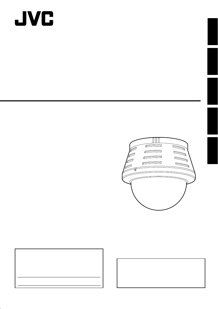
FIXED IP DOME CAMERA
VN-C215V4U
ENGLISH
DEUTSCH
FRANÇAISESPAÑOLITALIANO
START-UP GUIDE
For Customer Use:
Enter below the Serial No. which is located on
the body.
Retain this information for future reference.
Model No.
Serial No.
VN-C215V4U
Thank you for purchasing this JVC product.
Before beginning to operate this unit, please
read the instructions
carefully to ensure the best possible
performance.
LST0566-001A
Page 2

Introduction
Safety Precautions
FOR USA
These are general IMPORTANT SAFEGUARDS and certain items may not apply to
all appliances.
IMPORTANT SAFEGUARDS
1. Read all of these instructions.
2. Save these instructions for later use.
3. All warnings on the product and in the operating instructions should be adhered to.
4. Unplug this appliance system from the wall outlet before cleaning. Do not use liquid cleaners or
aerosol cleaners. Use a damp cloth for cleaning.
5.
Do not use attachments not recommended by the appliance manufacturer as they may cause hazards.
6. Do not use this appliance near water - for example, near a bathtub, washbowl, kitchen sink, or
laundry tub, in a wet basement, or near a swimming pool, etc.
7.
Do not place this appliance on an unstable cart, stand, or table. The appliance may
fall, causing serious injury to a child or adult, and serious damage to the appliance.
Use only with a cart or stand recommended by the manufacturer, or sold with the
appliance. Wall or shelf mounting should follow the manufacturer's instructions,
and should use a mounting kit approved by the manufacturer. An appliance and
cart combination should be moved with care.
Quick stops, excessive force, and uneven surfaces may cause the appliance and
cart combination to overturn.
8. Slots and openings in the cabinet and the back or bottom are pro-vided for
ventilation, and to insure reliable operation of the appliance and to protect it from
overheating, these openings must not be blocked or covered. The openings
should never be blocked by placing the appliance on a bed, sofa, rug, or other similar surface.
This appliance should never be placed near or over a radiator or heat register. This appliance should
not be placed in a built-in installation such as a bookcase unless proper ventilation is provided.
9.
This appliance should be operated only from the type of power source indicated on the marking label.
If you are not sure of the type of power supplied to your home, consult your dealer or local power
company. For appliance designed to operate from battery power, refer to the operating instructions.
10.For added protection for this product during a lightning storm, or when it is left unattended and
unused for long periods of time, unplug it form the wall outlet and disconnect the antenna or cable
system. This will prevent damage to the product due to lightning and power-line surges.
11.Do not allow anything to rest on the power cord. Do not locate this appliance where the cord will be
abused by persons walking on it.
12.Follow all warnings and instructions marked on the appliance.
13.Do not overload wall outlets and extension cords as this can result in fire or electric shock.
14.Never push objects of any kind into this appliance through cabinet slots as they may touch
dangerous voltage points or short out parts that could result in a fire or electric shock. Never spill
liquid of any kind on the appliance.
15.Do not attempt to service this appliance yourself as opening or removing covers may expose you to
dangerous voltage or other hazards. Refer all servicing to qualified service personnel.
16.Unplug this appliance from the wall outlet and refer servicing to qualified service personnel under
the following conditions:
a. When the power cord or plug is damaged or frayed.
b. If liquid has been spilled into the appliance.
c. If the appliance has been exposed to rain or water.
d. If the appliance does not operate normally by following the operating instructions. Adjust only those controls
that are covered by the operating instructions as improper adjustment of other controls may result in damage
and will often require extensive work by a qualified technician to restore the appliance to normal operation.
e. If the appliance has been dropped or the cabinet has been damaged.
f. When the appliance exhibits a distinct change in performance - this indicates a need for service.
17.When replacement parts are required, be sure the service technician has used replacement parts
specified by the manufacturer that have the same characteristics as the original part. Unauthorized
substitutions may result in fire, electric shock, or other hazards.
18.Upon completion of any service or repairs to this appliance, ask the service technician to perform
routine safety checks to determine that the appliance is in safe operating condition.
PORTABLE CART WARNING
(symbol provided by RETAC)
S3125A
E-2
Page 3
FOR USA AND CANADA
CAUTION
RISK OF ELECTRIC SHOCK
DO NOT OPEN
CAUTION
TO REDUCE THE RISK OF
:
ELECTRIC SHOCK. DO NOT
REMOVE COVER (OR BACK). NO
USER-SERVICEABLE
PARTSINSIDE.REFER SERVICING
TO QUALIFIED SERVICE
PERSONNEL.
The lightning flash wish arrowhead
symbol, within an equilateral triangle is
intended to alert the user to the presence of uninsulated "dangerous voltage" within the product's enclosure that
may be of sufficient magnitude to constitute a risk of electric shock to persons.
The exclamation point within an equilateral triangle is intended to alert the
user to the presence of important operating and maintenance (servicing)
instructions in the literature accompanying the appliance.
INFORMATION (FOR CANADA)
RENSEIGNEMENT
This Class A digital apparatus complies with
Canadian ICES-003.
Cet appareil num rique de la Classe A est
(POUR CANADA)
WARNING (FOR EUROPE):
This is a Class A product. In a domestic environment
this product may cause radio interference in which
case the user may be required to take adequate
measures.
Information for USA
This device complies with part 15 of the FCC Rules.
Changes or modifications not approved by JVC could
void the user's authority to operate the equipment.
This equipment has been tested and found to comply
with the limits for a Class A digital device, pursuant
to Part 15 of the FCC Rules. These limits are
designed to provide reasonable protection against
harmful interference when the equipment is operated
in a commercial environment. This equipment
generates, uses, and can radiate radio frequency
energy and, if not installed and used in accordance
with the instruction manual, may cause harmful
interference to radio communications. Operation of
this equipment in a residential area is likely to cause
harmful interference in which case the user will be
required to correct the interference at his own
expense.
This device complies with Part 15 of the FCC Rules.
Operation is subject to the following two conditions:
(1)This device may not cause harmful interference,
and (2) this device must accept any interference
received, including interference that may cause
undesired operation.
WARNING:
TO REDUCE THE RISK OF FIRE OR
ELECTRIC SHOCK, DO NOT
EXPOSETHIS APPLIANCE TO RAIN
OR MOISTURE.
AVERTISSEMENT:
POUR EVITER LES RISQUES
D'INCENDIE OU D'ELECTROCUTION, NE PAS EXPOSER
L'APPAREIL A L'HUMIDITE OU A LA
PLUIE.
Due to design modifications, data given in this
instruction book are subject to possible change
without prior notice.
ENGLISH
E-3
Page 4
Introduction
Safety Precautions (continued)
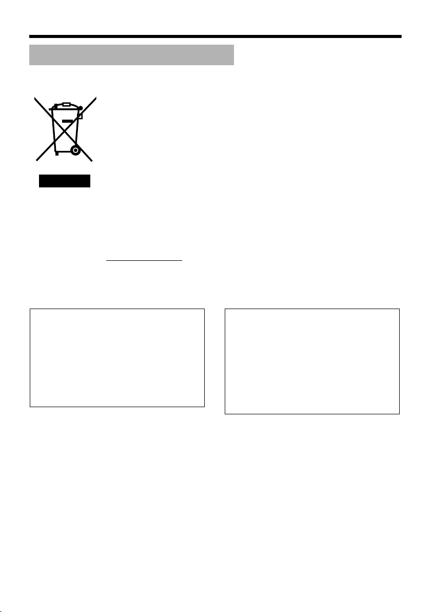
Information for Users on Disposal of Old Equipment
[European Union]
This symbol indicates that the electrical and electronic equipment should not be
disposed as general household waste at its end-of-life. Instead, the product
should be handed over to the applicable collection point for the recycling of
electrical and electronic equipment for proper treatment, recovery and recycling
in accordance with your national legislation.
By disposing of this product correctly, you will help to conserve natural resources
and will help prevent potential negative effects on the environment and human
health which could otherwise be caused by inappropriate waste handling of this
product. For more information about collection point and recycling of this product,
please contact your local municipal office, your household waste disposal service
Attention:
This symbol is
only valid in
the European
Union.
Dear Customer,
This apparatus is in conformance with the valid
European directives and standards regarding
electromagnetic compatibility and electrical safety.
European representative of Victor Company of
Japan Limited.is:
JVC Technology Centre Europe GmbH
P.O.Box100552
61145 Friedberg
Germany
or the shop where you purchased the product.
Penalties may be applicable for incorrect disposal of this waste, in accordance
with national legislation.
(Business users)
If you wish to dispose of this product, please visit our web page
www.jvc-europe.com to obtain information about the take-back of the product.
[Other Countries outside the European Union]
If you wish to dispose of this product, please do so in accordance with
applicable national legislation or other rules in your country for the treatment of
old electrical and electronic equipment.
Sehr geehrter Kunde, sehr geehrte
Kundin,
dieses Gerät stimmt mit den gültigen europäischen
Richtlinien und
Normen bezüglich elektromagnetischer
Verträglichkeit und elektrischer
Sicherheit überein.
Die europäische Ver tretung für die Victor Company
of Japan, Limited ist:
JVC Technology Centre Europe GmbH
Postfach 100552
61145 Friedberg
Deutschland
E-4
Page 5

● This installation should be made by a
qualified service person and should conform
to all local codes.
● This installation shall be in accordance with
the National Electrical Code, ANSI/NFPA 70.
● The unit is to be powered by an DC 12 V
power supply.
● The DC 12 V power supply should conform to
the following: Class 2 only (For USA),
Isolated power supply only (For Europe and
other).
● Any Mention in this manual of Alarm inputs/
outputs have not been evaluated by UL to be
used for Burglar Alarm Functionality.
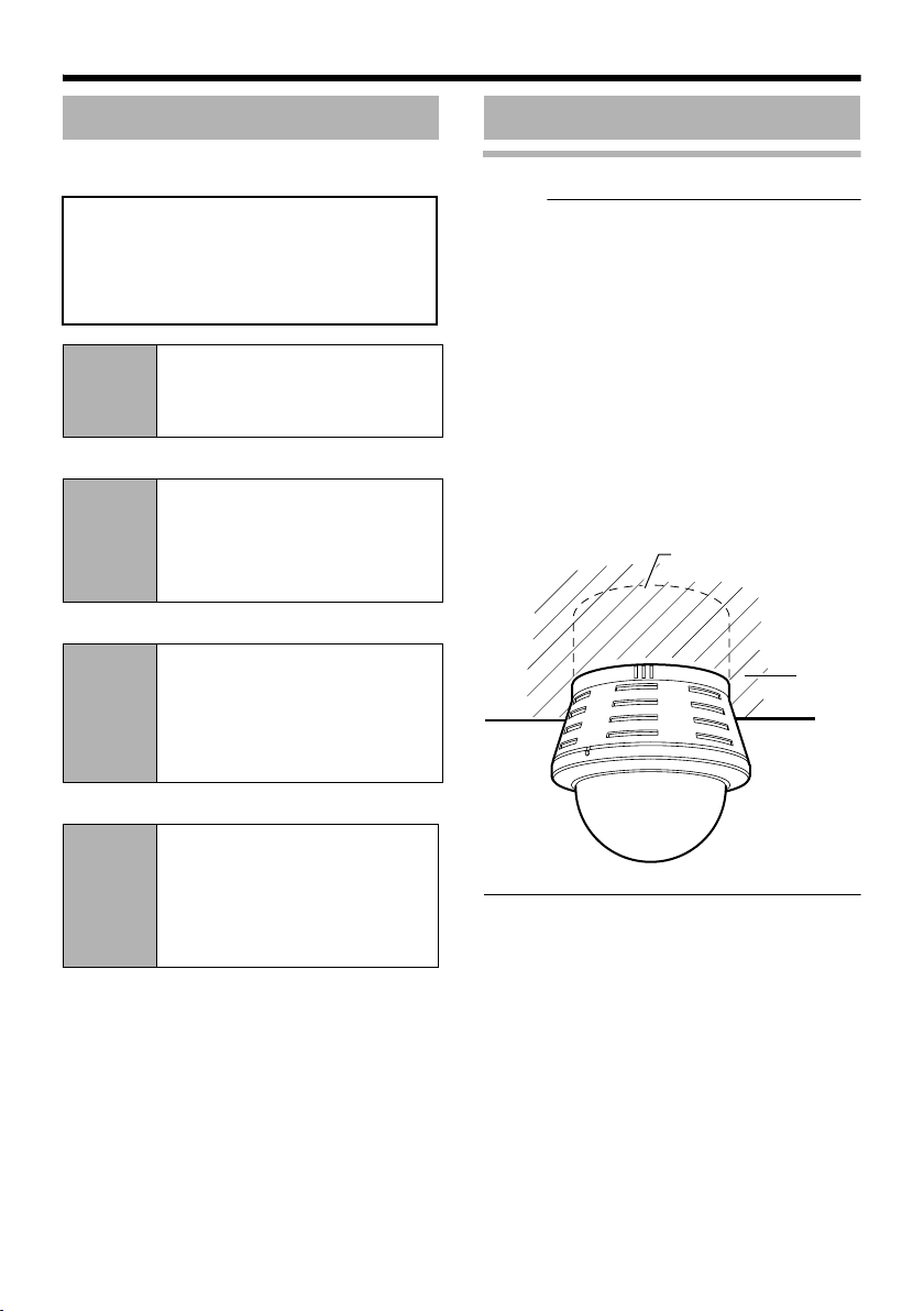
● Embedding of cameras in the ceiling may not
be allowed due to regulations in some
regions. Please consult your nearby
authorized JVC dealer for more details.
● The ceiling to mount the camera has to be
strong enough to support the weight of this
product. If the ceiling is not strong enough,
make sure to apply reinforcement to the
ceiling before installation.
● The rating label is placed on the side of the
camera unit.
● The camera unit may fall if the mounting
screws and nuts are not properly tightened.
Ensure that the screws and nuts are properly
tightened.
● We do not accept liability for any damage to
the camera in cases when it is dropped
because of incomplete installation due to not
observing the installation instructions
correctly. Please be careful when installing
the camera.
● Do not install the camera near lighting
equipment with a high temperature, such as
spotlights. Doing so may cause malfunction
or fire.
This manual describes basic usage of VNC215V4U.
For detailed usage of VN-C215V4U, please
refer to AINSTRUCTIONSB.
For latest information, please refer to
AReadmeB file in the supplied CD-ROM.
● The supplied CD-ROM includes
[INSTRUCTIONS] (pdf), [API Guide] (pdf)
and [Search Tool].
● To view file in pdf format, the installation of
AAdobe ReaderB on the Computer is
required.
ENGLISH
● Before starting an important recording, be
sure to perform a test recording in order to
confirm that a normal recording is possible.
● We will not provide any compensation
whatsoever for the contents to be recorded
or loss of opportunities when recording is
not properly performed due to malfunction
of the video camera, VTR, hard disk
recorder or video tape.
● Prior to adjusting the shooting direction of
the camera, touch the metal surface of the
[MONITOR] terminal with your hand to
discharge static electricity from your body.
E-5
Page 6

Introduction
Main Features
䡵 High Picture Quality
The camera unit of VN-C215V4U employs a
380,000-pixel CCD (1/4") which enables high
quality image monitoring.
䡵 Wide shooting range
The adjustment range of the shooting direction is
wide and the camera can be mounted on a wall
with the use of a rotation adjustment
mechanism.
䡵 Unblocked Design
The dome-shaped design enables ease of use
without being blocked by the camera.
䡵 Embed in ceiling without use of
brackets
The camera unit can be embedded in the ceiling
without the use of recess brackets.
䡵 High-power varifocal lens
The built-in varifocal lens (optical zoom 3.6x)
makes detailed surveillance possible.
䡵 Night surveillance
VN-C215V4U comes with a low luminance
feature (Easy Day and Night), which switches
automatically to the high sensitivity mode (blackand-white) under low illumination.
䡵 Support for PoE (Power over
Ethernet)
VN-C215V4U supports PoE (IEEE802.3af) and
enables power supply from a LAN cable.
䡵 Realization of Full Frame Rate
Data transmission is possible in VGA size at a
rate of 30 fps.
䡵 Built-in Web Server
Setting is possible using the Internet Explorer.
䡵 Support for Multicast
VN-C215V4U supports multicast, which enables
transmission of an image data to multiple
computers on the network without lowering the
frame rate.
䡵 Motion Detection Feature
This feature enables output of an alarm upon
detection of motion in the image within a preset
area.
Pre-recorded/post-recorded image files can be
sent via FTP using the alarm input.
䡵 Built-in Viewer
Monitoring via a computer is possible by
downloading the built-in viewer onto the
computer.
䡵 HTTP-based API
VN-C215V4U comes with a HTTP-based API.
This feature enables setting and control via the
network.
How to view this manual
䡵 Symbols used
Note : Describes items concerning the
operation of this product.
Memo : Describes reference information,
such as functions and usage
restrictions of this product.
A : Indicates the reference page
numbers and reference items.
䡵 About the contents of this manual
● All rights reserved by JVC. Unauthorized
duplication or reprinting of this manual, in
whole or in part, is strictly prohibited.
● Windows is a registered trademark of
Microsoft Corporation in the U.S.
● All other product names used in this
manual are trademarks or registered
trademarks of their respective companies.
Note that marks such as 姠, 姞 and 姝 have
been omitted in this manual.
● Illustrated designs, specifications and other
contents of this manual are subject to
change for improvement without prior
notice.
E-6
Page 7

Contents
Introduction
Safety Precautions ............................. 2
Main Features ..................................... 6
Contents ............................................. 7
Operating Environment ....................... 8
Cautionary Notes ................................ 8
Name and Function of Parts ............. 10
Features ........................................... 14
Setup
Overall Procedures ........................... 16
Mounting the Camera ....................... 16
Before Mounting ............................ 16
Selecting Mounting Method ........... 17
Mounting on a ceiling .................... 17
Mounting the camera directly on a
ceiling or alongside a wall ...... 20
Mount by allowing the cable to exit
from the side ........................... 22
Mo unt ing the cam era
to the electrical box ................ 22
Power Connection ............................ 24
Using the PoE ............................... 24
Connecting to the DC12 V
power supply .......................... 25
LAN Cable Connection ..................... 26
Alarm Input/Output
Cable Connection ...................... 26
Image adjustment ............................. 27
Mounting the Dome Cover ................ 29
Setting
Network Requirements .....................30
IP Address Settings ..........................31
T For ASetting Using Internet
ExplorerB, please refer to the
[INSTRUCTIONS] (pdf) in the
supplied CD-ROM.
Operation
Operation of Built-in Viewer .............. 37
Setting Up the Internet Explorer ....38
Installing the built-in viewer ........... 40
Screen Configuration of Built-in
Viewer ..................................... 41
Quitting the Built-in Viewer ............ 42
Shortcut for Built-in Viewer ............ 43
Others
Specifications ....................................44
ENGLISH
E-7
Page 8

Introduction
Operating Environment
䡵 PC Specification Requirements
OS : Windows XP (Professional or
Home Edition) (SP2)
CPU : Pentium4 1.5 GHz (or higher)
Memory : 1 GB and above
Hard disk space : Free space of 20 MB and
above
Video card : 1024 ⳯ 768 pixels or higher,
True Color (24 or 32 bits)
Web browser : Internet Explorer Version 6.0
䡵 LAN Environment
● 10BASE-T/100BASE-TX network
interconnected using an IEEE802.3compliant switching hub.
● IEEE802.3af-compliant switching hub when
PoE is in use.
● IGMPv2-compliant network when multicast is
in use.
Memo :
● The above PC specifications are merely
guides for smooth use of the applications,
and not a guarantee of their operation.
● Depending on the condition of use,
applications may not run smoothly even
when the user’s computer meets the
specification requirements.
Cautionary Notes
Maintenance and operating
environment
䢇 This camera is intended for use indoors. It
cannot be used outdoors.
䢇 Do not store in the following environments.
It might result in malfunctions or failure.
● Hot or cold locations beyond the
surrounding temperature range of -10I to
50I.
● Locations beyond the allowable operating
humidity range of 35 % RH to 85 % RH.
(condensation is not allowed)
● Near equipment that produces strong
magnetic fields, such as transformers or
motors.
● Near equipment that emits radio waves,
such as transceivers and mobile phones.
● Locations with excessive dust and sand.
● Locations that are subject to excessive
vibration.
● Locations prone to moisture such as
window side.
● Locations subject to steam or oil, such as
kitchens.
● Locations that emit radiation, X-rays or
corrosive gases.
䢇 Use of this product and cables connected to
this product at locations where strong electric
waves and magnetic waves are generated
(e.g., near radio, TV, transformer, monitor,
etc.) may cause noise interferences in the
images or changes in the color.
䢇 Do not install at locations where cold air is
circulated, such as near the air vent of an air
conditioner. The drastic change in
temperature may fog up the dome cover.
䢇 Do not install at locations that may trap heat.
This product also discharges heat from the
surface of the main unit. As such, do not
install it at locations that may trap heat, such
as wall corners.
E-8
Handling of Equipment
䢇 Do not block vents around the equipment.
Inadequate heat ventilation may result in
malfunction of this product. Be sure not to
block vents around the product.
Page 9

Others
䢇 This product has a built-in AGC circuit. When
AGC is AOnB, the product sensitivity
increases automatically at dark places and
the image on the screen may appear grainy.
This is not a malfunction.
䢇 When White Balance is set to AAutoB, the
principle of automatic tracking white balance
circuit may cause the color of the image to be
different from the actual color of the object,
depending on the condition of the object.
However, this is not a malfunction.
䢇 If a high-intensity object (such as a lamp) is
shot, vertical lines may appear on the image
(smear phenomenon) or blurring may occur
around the high-intensity object (blooming
phenomenon). This is a CCD characteristic
and is not a malfunction.
䢇 The electronic shutter of this product is set to
1/60 by default. To prevent flickering under
fluorescent lighting (except inverter
illumination) in a location with commercial
power frequency of 50 Hz, switch the shutter
speed to 1/100. (The sensitivity decreases a
little when the shutter speed is 1/100.)
䢇 When Easy Day and Night is set to AOnB, the
image becomes black and white in dark
locations. As the sensitivity is increased at
this time, the screen may appear grainy and
white spots may also increase. In addition,
when color images are changed to black and
white, bright areas of the screen are
emphasized and they may be difficult to see.
However, this is not a malfunction.
䢇 The image may be distorted or be mixed with
noises when the power voltage is cut off
instantaneously or is lowered by a lightning
strike or by switching on an air conditioner.
䢇 The rotation angle of this product is set to
wide angle to support wide range equipment.
When the lens zoom is wide and the tilt angle
is approximately ±80 ⬚, the rotation angle
may cause the dome cover to be reflected in
the image. In this case, adjust the field angle
if required. (A Pg. 29)
䢇 When multicast is in use, use the IGMPv2-
compliant network switch.
䢇 Electricity can be supplied to this product
either by using the PoE or connecting to the
DC12 V power supply. Make sure to select
only one mode of electrical supply.
Connecting the power cable and the LAN
cable for the PoE at the same time may result
in failure or malfunction of the camera.
(A Pg. 24, 25)
Copyrights of video
䢇 With the exception of the user being the
copyright holder or when permission has
been granted concerning duplication, etc. by
the copyright holder, permission is required in
principle for the duplication, modification,
transmission, etc. of copyrighted video/audio.
Unauthorized duplication, modification,
transmission, etc. of copyrighted material
may constitute a copyright infringement and
the user may be liable to compensate for any
damages. When using copyrighted video/
audio, be sure to check thoroughly the
license agreement, etc. of the copyrighted
material.
When there are rights or rights holders of the
duplicating subject, permission may be
required for shooting or using (processing) it.
Be sure to check thoroughly the licensing
conditions.
Maintenance
䢇 Be sure to turn off the power before
performing maintenance.
䢇 Wipe using a soft cloth.
Wiping with thinner or benzene may dissolve
or tarnish its surface. For dirt that cannot be
easily removed, wipe using a neutral
detergent diluted with water, followed by
wiping with a dry cloth.
Saving Energy
䢇 When not in use for a long period, turn off the
power of the system to prevent risk and to
reduce power consumption.
ENGLISH
E-9
Page 10
Introduction
Name and Function of Parts
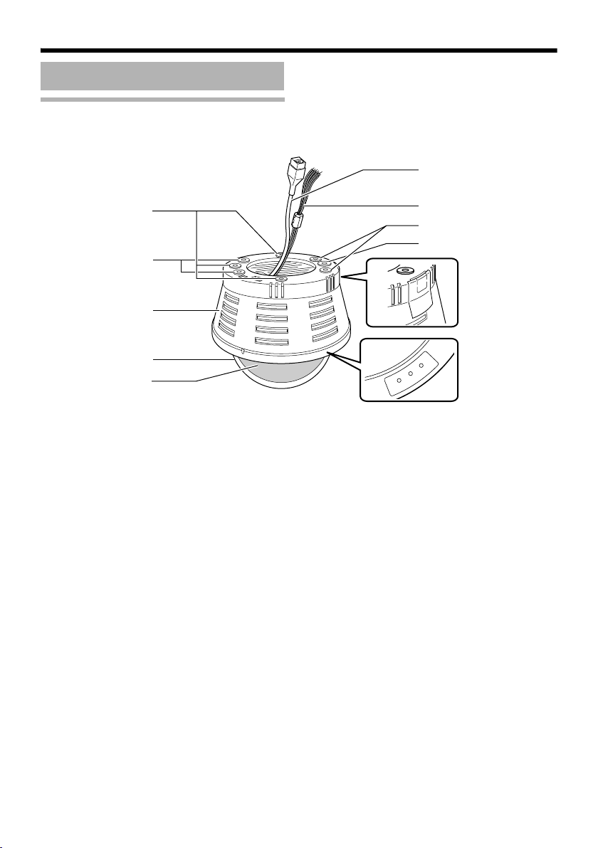
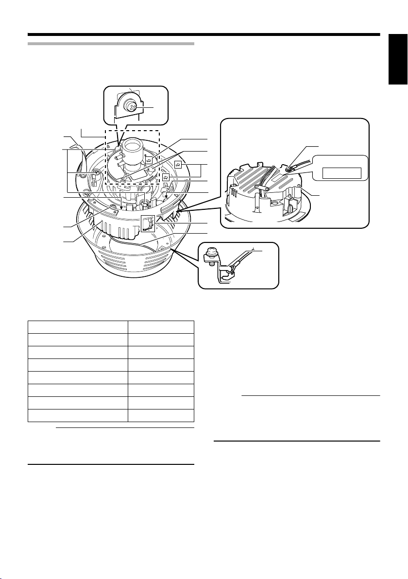
Camera unit
I
A
B
C
D
E
Mounting hole (elliptical) ⳯ 4
A
Use these when mounting the camera to the
electrical box.
(A Pg. 22)
B Mounting hole (round) ⳯ 4
Use these when mounting the camera to the
ceiling or wall. (A Pg. 20, 22)
C Outer case
Use this in the following cases:
● When mounting the camera directly to the
ceiling or on the wall. (A Pg. 20)
● When mounting the camera to the electrical
box. (A Pg. 22)
D Dome cover
The dome cover is fragile. Take care when
handling it.
E Inner dome
Before mounting the camera, remove it and
perform image angle setting. (A Pg. 18, 20)
H
B
A
G
F
Status
Link
Act
F Operation check indicator
[Status] Status indicator
This indicator appears blinking when the power
is turned on and turns off when the camera
startup is completed. Check the camera or the
connected device if the indicator remains
blinking when the camera is in use.
[Link] Link indicator
This indicator lights up when the camera is
linked or connected to the network.
[Act] Activity indicator
This indicator lights up during an activity such as
data transmission or reception.
G Cable ejector hole
This is used for pulling cables from the side of
the camera unit without drilling a hole in the
ceiling.
(A Pg. 22)
E-10
Page 11
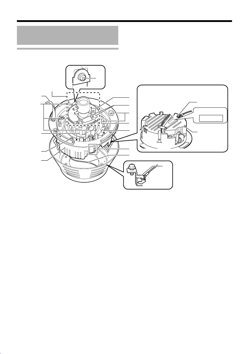
Camera unit/Inside the camera
Not
Not
T This is when the dome cover, inner cover and outer case is removed.
How to remove ( A Pg. 17 AMounting on a ceilingB Steps 3. to 5.)
ENGLISH
Lens section
(A Pg. 13)
W
J
K
L
M
N
H Power supply/Alarm signal cable
(A Pg. 24, 26)
Signal name Cable color
Alarm input 1 Pink
Alarm input 2 Blue
Alarm output 1 Orange
Alarm output 2 Yellow
GND Brown
DC 12 V power supply+ Red
DC 12 V power supply- Black
e :
● Do not use PoE together with DC 12 V power
supply. Simultaneous connection will cause
failure or malfunction.
I [10BASE-T/100BASE-TX(PoE)] Connector
for LAN cable connection (RJ-45)
(A Pg. 26)
J Strap
This sheet connects the camera unit to the dome
cover.
Behind the camera unit
V
U
T
P
Y
MAC address
S
R
X
Q
P
O
K Fastening screw (x3)
This is the screw head of the ceiling mounting
bracket Q, which is used to embed the camera
in the ceiling.
L [RESET] Reset button
This is a button for rebooting the camera. Press
this button and release within 5 seconds to
reboot the camera. It takes about 1 minute for
the camera to reboot. During startup, [RESET]
button is disabled.
e :
● Pressing the [RESET] button for 5 seconds
or longer switches the camera to the service
verification mode. Do not press the button for
5 seconds or longer.
M [MONITOR] Monitor terminal (RCA pin)
(A Pg. 27)
N Camera unit
O Fall-prevention wire fastening hook
P Fall-prevention wire (supplied) and wire
mounting screw
Connect the camera unit N and the outer case C
with the fall-prevention wire fastening screw
O
.
E-11
Page 12
Introduction
Name and Function of Parts
(continued)
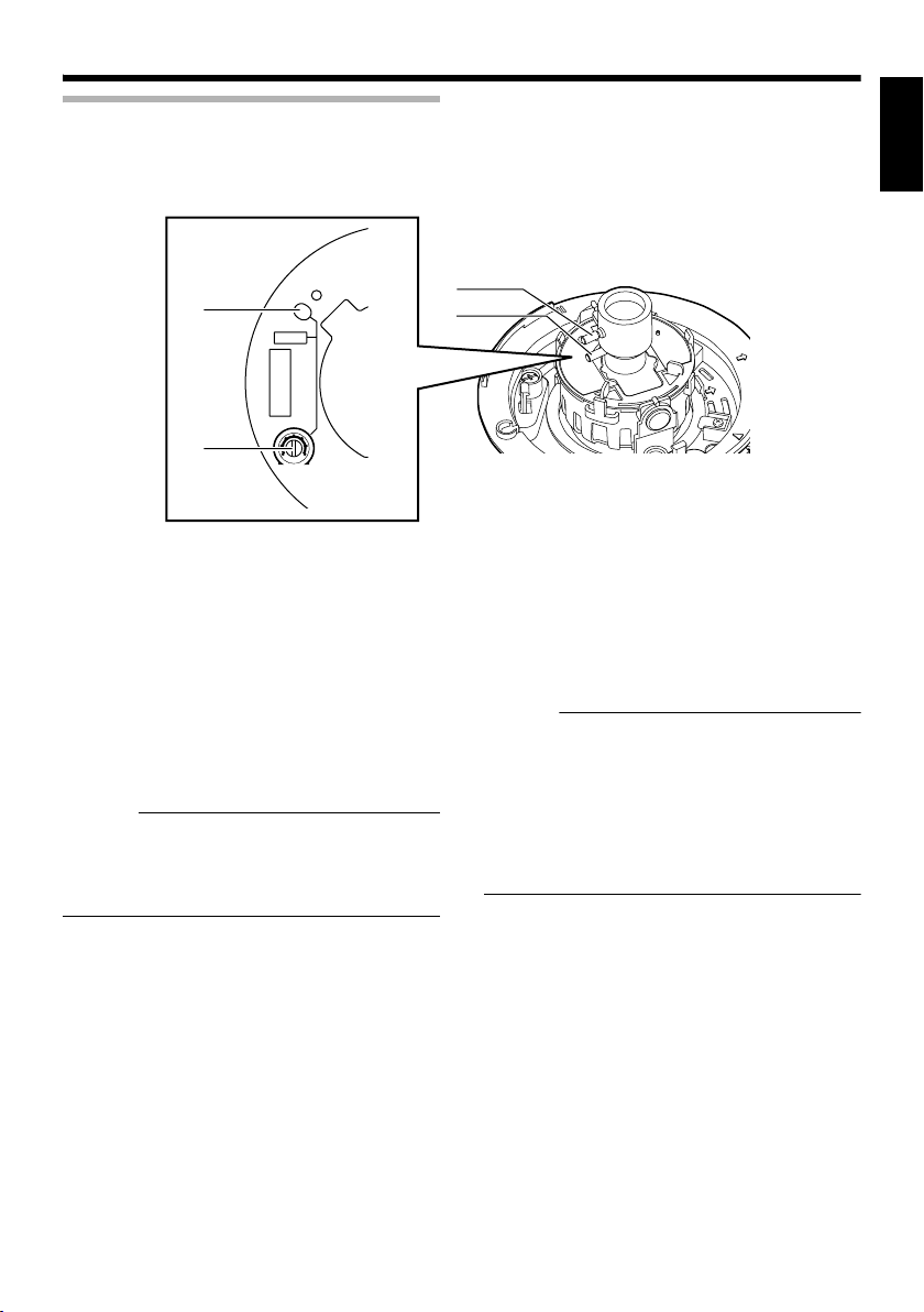
Inside the camera
Lens section
(A Pg. 13)
W
J
K
L
M
N
Q Ceiling Mount Bracket (x3)
This serves as a bracket when embedding the
camera in a ceiling. (A Pg. 17)
R Camera Fastening Screw
This secures the camera unit N and the outer
case C. How to remove (A Pg. 18, 20)
S Pan fastening screw
Make sure you loosen the screw before setting.
Only tighten the screw when using the camera in
locations with vigorous vibrations so that the
camera shooting direction is not misaligned.
(A Pg. 28)
T Imaging Direction mark
Install the camera facing the arrow in the
shooting direction.
U Rotation Knob
This knob rotates the lens sections and adjusts
the tilting of the image. (A Pg. 28)
V Rotation center mark
(A Pg. 28)
Behind the camera unit
V
U
T
P
Y
MAC address
S
R
X
Q
P
O
W Tilt fastening screw
After adjusting the field angle, tighten the screw
so that the camera field angle will not be
misaligned when using the camera in locations
with vigorous vibrations. (A Pg. 28)
X Fall-prevention wire mounting hole and
screw
This is used to mount the fall-prevention wire
from the ceiling.
(The fall-prevention wire is not supplied.)
Y [MAC address] MAC address indicator
The MAC address is a unique physical address
of the product. This address cannot be altered.
E-12
Page 13
Lens section
ENGLISH
SPOT
Z
a
[FOCUS ADJ] Focus adjustment button
Z
FOCUS ADJ
IRIS ADJ
FOR SERVICE
L
IRIS
LEVEL
H
This is used to adjust the lens focus.
Press the button to open the lens Iris for 30
seconds. The focus is now easier to adjust as
the depth of field becomes shallow. (A Pg. 29)
Memo :
● Pressing the focus adjustment button
automatically activates the electronic shutter.
The screen may flicker but this is not a
malfunction.
a [IRIS LEVEL] Iris level adjustment dial
This dial adjusts the Iris level of the auto iris
lens.
Normally, adjustment is not required. Adjust if
required, depending on the conditions of the
object.
To darken : Anti-clockwise direction (towards L)
To brighten : Clockwise direction (towards H)
b
c
Memo :
● Adjust the Iris level after [AGC] is set to
AOffB. For AAGC function settingsB, please
refer to the [INSTRUCTIONS] (pdf) in the
supplied CD-ROM.
● If AOffB is not set, turning the dial towards L
will activate the AGC function. The camera
sensitivity increases and the image quality
becomes grainy.
b Focus adjustment ring
Move the ring horizontally to adjust the focus.
(A Pg. 29)
c Zoom adjustment ring
Move the ring horizontally to adjust the field
angle. (A Pg. 29)
E-13
Page 14
Introduction
Features
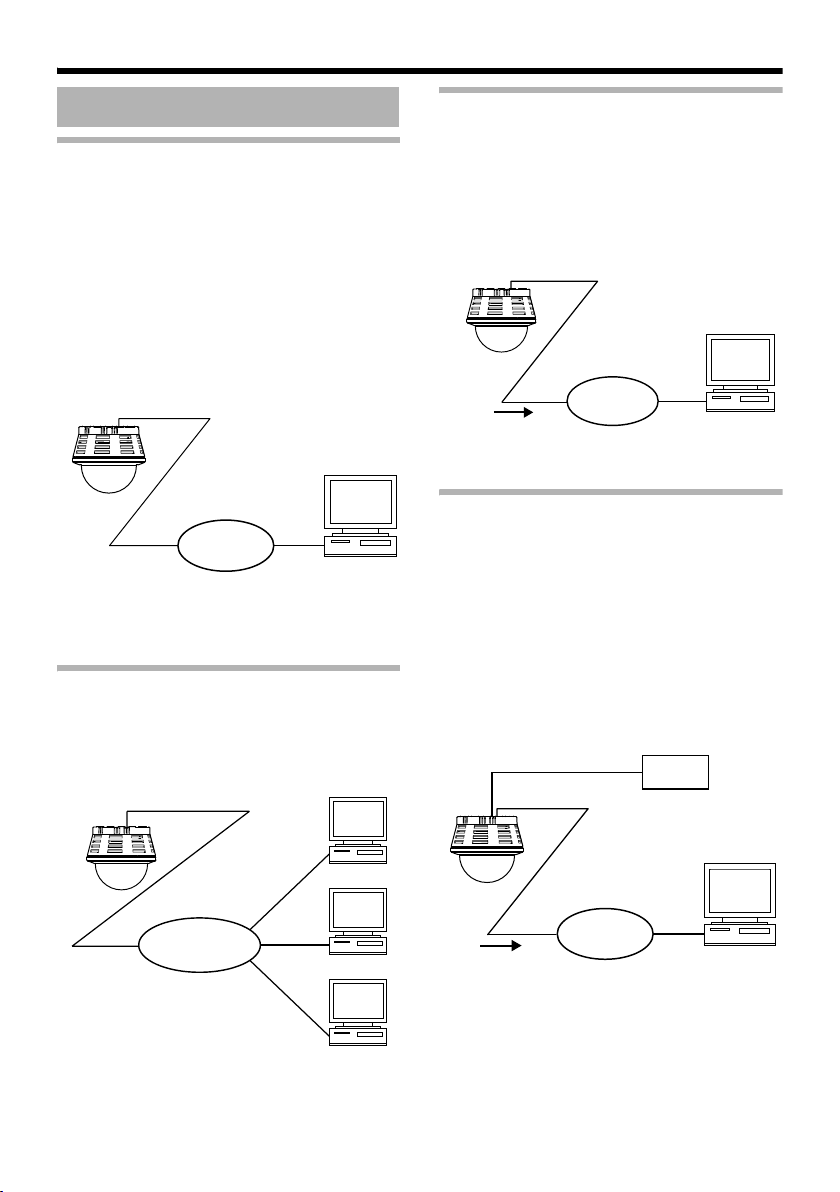
Monitoring Via Built-in Viewer
VN-C215V4U comes with a built-in ActiveX
viewer.
Monitoring of VN-C215V4U images using the
computer is possible by installing this built-in
viewer on the computer. Images that are
currently displayed may also be captured in the
computer’s hard disk.
AOperation of Built-in ViewerB (A Pg. 37)
VN-C215V4U
Network
Computer
Monitoring Via Multicast
Monitoring using multiple computers is possible
via multicast.
Saving JPEG images to the FTP server
at regular intervals
JPEG images may be uploaded to the FTP
server at regular intervals.
VN-C215V4U
Sending latest
images to FTP
regularly
Network
Computer
Alarm
VN-C215V4U comes with a motion detection
feature and dual alarm input.
By motion detection or alarm input, action such
as mail delivery, message transission via
TCP/UDP, alarm output can be triggered.
Combination of alarm inputs can be trigger.
Installing an FTP server enables uploading of
images before and after the alarm input time
(pre-/post-recording) to the server.
VN-C215V4U
VN-C215V4U
E-14
IGMPv2
compliant
Network
Computer
Computer
Computer
Sending images
before and after
alarm input
Alarm Device
Network
Computer
Page 15

Restrictions on Clients
It is possible for VN-C215V4U to permit or deny
image acquisition of designated IP addresses.
Control via customized application
software
The following uses are also possible by
developing a customized application software
that supports the API of VN-C215V4U.
For details, please refer to the [API Guide] in the
attached CD-ROM.
● Monitoring via the computer while at the
same time recording images to the HDD.
● Recording by changing the frame size/frame
rate during alarm occurrence.
● Recording the type and time of alarm
occurrence to the computer.
● For detailed usage of VN-C215V4U ,
please refer to [INSTRUCTIONS] (pdf) in
the supplied CD-ROM.
ENGLISH
E-15
Page 16
Setup
Not
Overall Procedures
The connection and setup procedures are
described as below.
䢇 Make sure you touch the metal surface of
the [MONITOR] terminal to release the
static electricity from your body. Static
electricity may cause the camera to
malfunction.
Step 1
K
Step 2
K
Step 3
Setup (A Pg. 16)
Mount the camera and configure
image settings.
Network Settings
(A Pg. 30)
Configure the network settings of
the computer and this camera.
Internet Explorer Settings
T For details, please refer to the
[INSTRUCTIONS] (pdf) in the
supplied CD-ROM.
Mounting the Camera
Before Mounting
e :
● Make sure you put on protective glasses to
protect your eyes from falling objects when
mounting the camera on the ceiling.
● Attachment of a embedded cover in the
ceiling (recess bracket) may be mandatory in
certain regions.
● If this is so, ensure that the embedded cover
(recess bracket) is securely attached before
installing the camera.
● Please refer to the instruction manual for the
cover in use for details on installation of the
embedded cover (recess bracket).
● For detail related to embedded cover (recess
bracket), please contact JVC.
Embedded Cover in
Ceiling ( Recess Bracket)
Ceiling
K
Step 4
E-16
Operation of Built-in Viewer
(A Pg. 37)
Monitoring and still image saving
operations are possible using the
built-in viewer.
Page 17
Selecting Mounting Method
Not
Not
The procedures differ according to the mounting
method. Check the respective items before
mounting.
e :
● To mount the camera using an electrical box,
please check with your dealer or nearest JVC
servicing center.
Mounting Method
䢇 Mounting on a ceiling (A Pg. 17)
䢇 Mounting directly on a ceiling or
alongside a wall (A Pg. 20)
䢇 Mounting by pulling cables horizontally
(A Pg. 22)
䢇 Mounting the camera to the electrical
box
(A Pg. 22)
Warning
● Special attention is required when
mounting the camera to a wall or ceiling.
Mounting operations should not be carried
out by the users but by professional
contracters. Failure to do so may cause the
camera to fall and result in injuries and
accidents.
● JVC is not liable for any compensation if
you drop the camera due to insecure
mounting by not following the installation
description. Pay careful attention during
installation.
● To prevent the camera from falling, ensure
that it is connected to a firm place (ceiling
slab or channel) using a fall-prevention
wire.
● Also pay careful attention to the length,
strength, wiring and material (insulation
quality) of the fall-prevention wire to be
used.
● The camera may drop if the mounting
screws or nuts are not tightened securely.
Check that the screws are tightened
appropriately and securely.
● Do not install the camera near lighting
fixtures of high temperature, such as spot
lights. It might result in failure or fires.
Mounting on a ceiling
T The thickness of the ceiling material should
be between 9.5 mm and 22 mm.
䡵 Setup
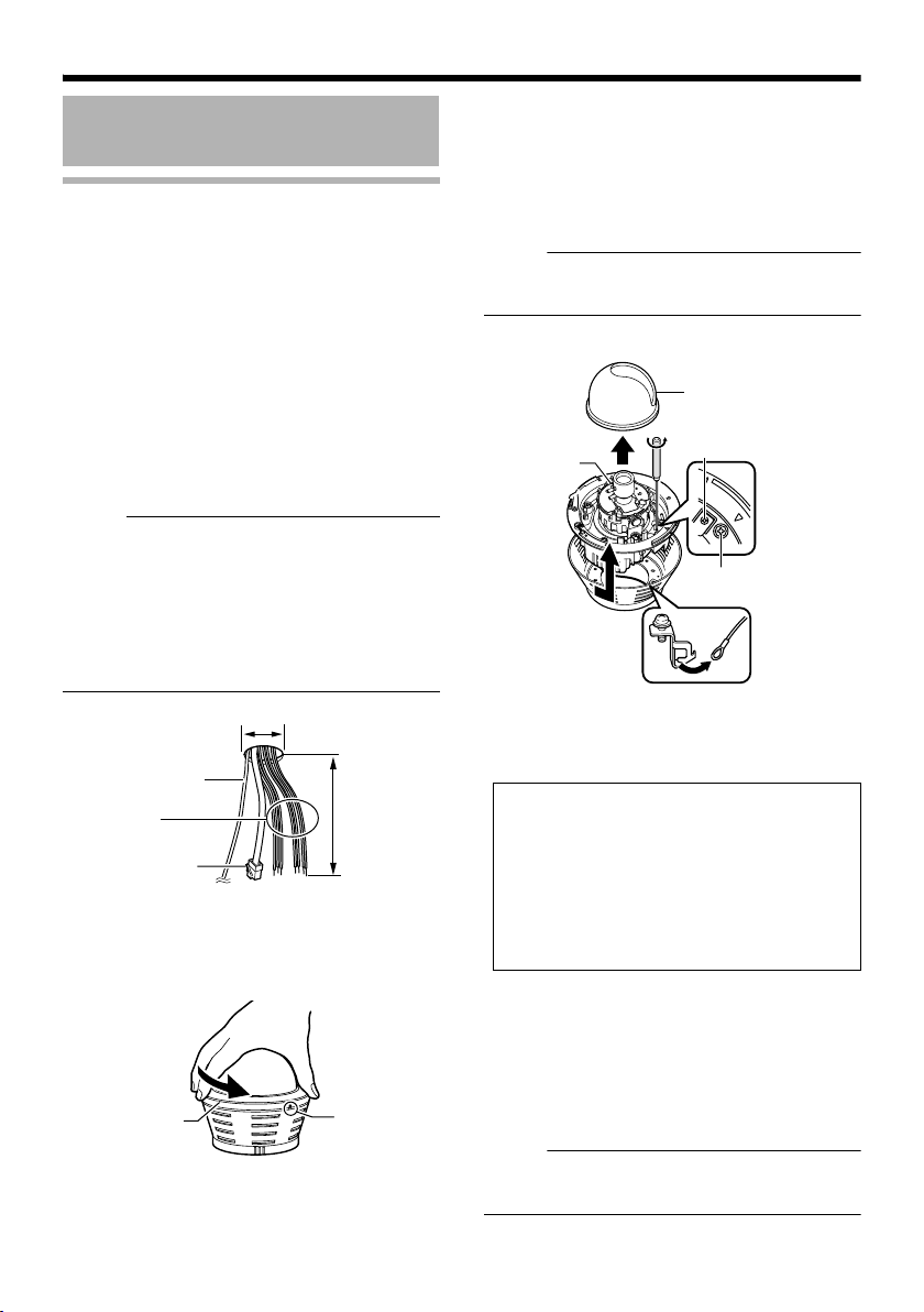
1.Open a hole in the ceiling (R120 mm,4-3/4
inches)
2.Draw the cables from the ceiling.
Draw the fall-prevention wire, LAN cable, power
cable and alarm cable from the ceiling. These
are mounted beforehand on the ceiling slab.
(The fall-prevention wire is not supplied.)
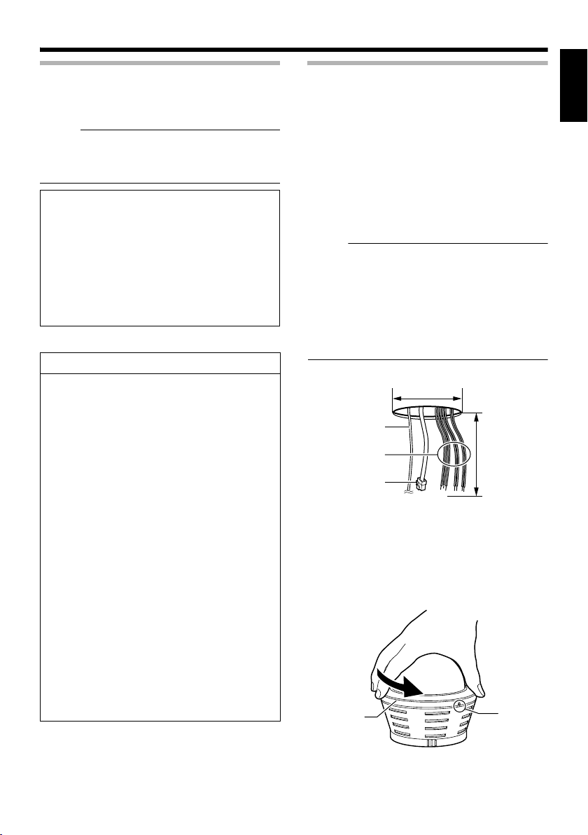
e :
● Also pay careful attention to the length,
strength, wiring and material (insulation
quality) of the fall-prevention wire to be used.
● For the fall-prevention wire, the inside
diameter of the ring section to be mounted on
the camera unit should be between R3.1 mm
and R5.5 mm, and the outside diameter
should be below R9 mm.
R120 mm
(4-3/4 inches)
1
Fall-prevention wire
(not supplied)
Power cable, alarm
cable
LAN cable
3.Remove the dome cover
As shown in the picture, hold the dome ring such
that the position alignment mark is between your
thumb and index finger. Turn the dome ring in
the anti-clockwise direction and remove.
Dome ring
Approx. 100 mm
(3-7/8 inches)
2
Position
alignment
mark
ENGLISH
E-17
Page 18
Setup
Not
Mounting the Camera
(continued)
Mounting on a ceiling (continued)
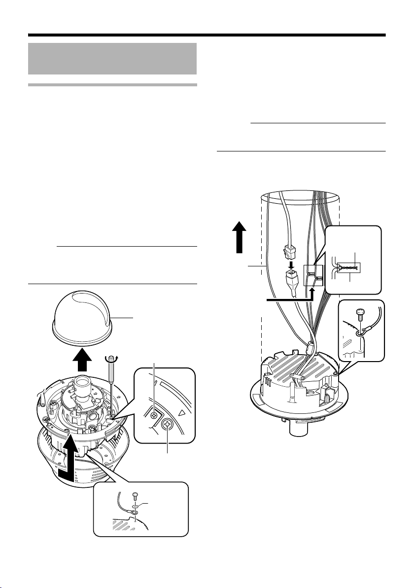
4.Remove the inner dome.
The inner dome is secured by 3 clips. Remove
the inner dome from the clips.
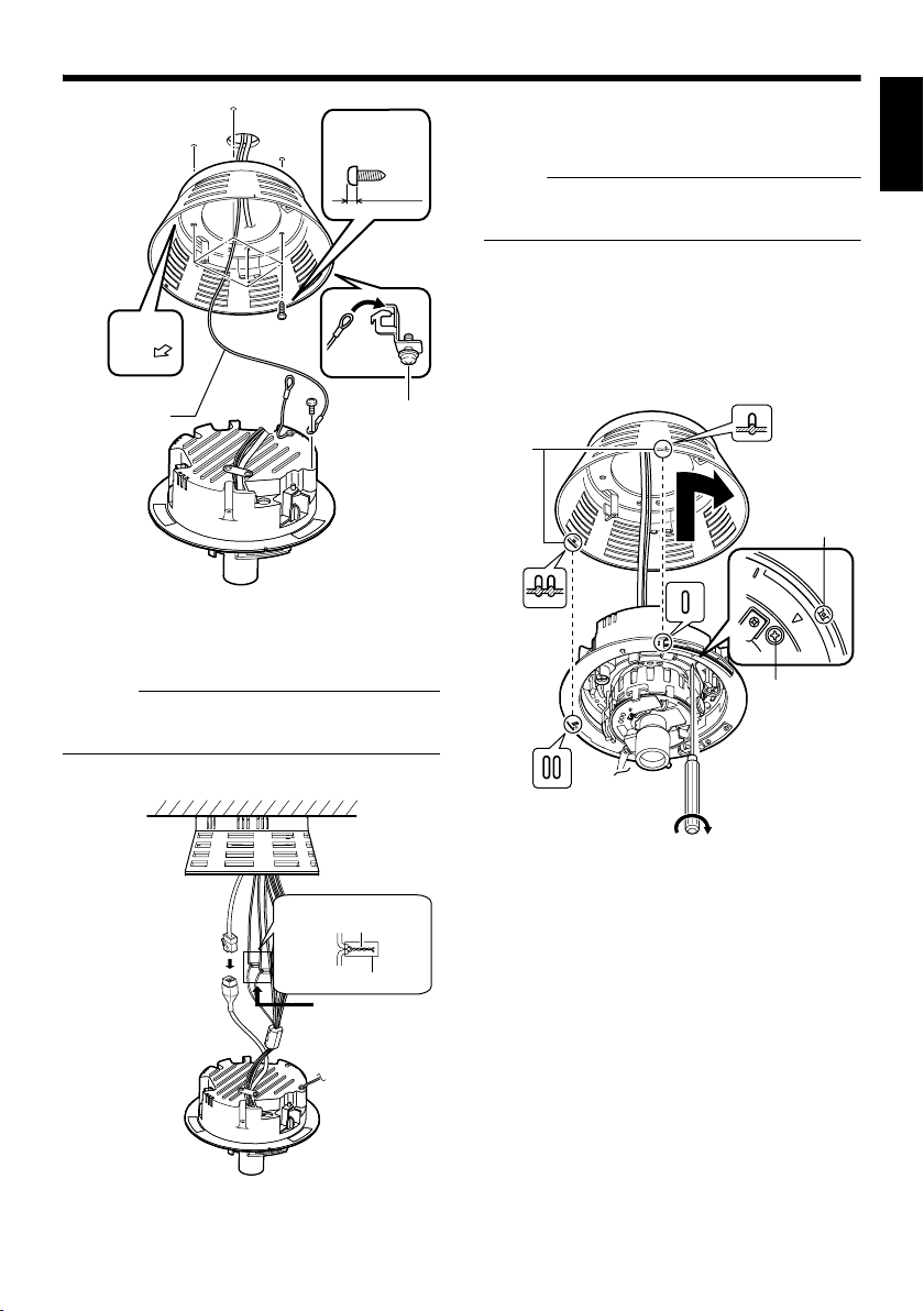
5.Remove the outer case.
(The outer case is not used for this mounting
method.)
A Loosen the camera fastening screws with a
screwdriver.
B Turn the camera in the anti-clockwise
direction and remove the outer case.
6.Remove the fall-prevention wire.
Remove the fall-prevention wire that is attached
to the camera unit.
7.Loosen the pan fastening screw.
e :
● The lens section may be damaged if you
operate it without loosening the pan fastening
screw.
Inner dome
䡵 Connection
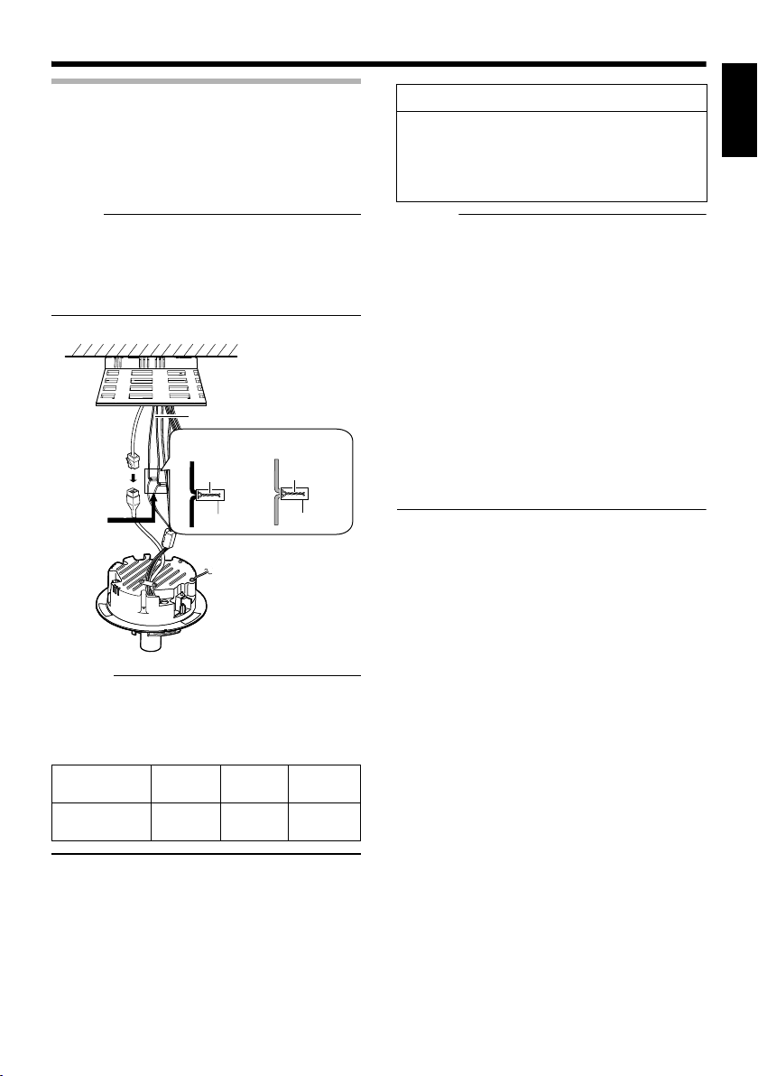
1.Mount the fall-prevention wire on the
camera. This wire connects the camera to the
ceiling.
2.Connect the LAN cable. (A Pg. 26)
3.Connect the power cable and the alarm
cable. (A Pg. 24, 26)
Memo :
● The power cable must not be connected
when PoE is used.
4.Wind the waterproof tape.
5.Insert the camera in the ceiling hole.
3
3
Solder or crimp
Insulation tape
1
Fall-
prevention
wire(not
supplied)
Wind the
waterproof tape.
2
4
5
E-18
B
4
Pan fastening screw
7
A
5
Camera
Fastening
Screw
6
Washer
Page 19
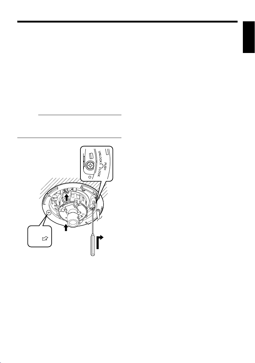
䡵 Mounting
1.Face the imaging direction mark (j) in the
shooting direction and mount the camera.
2.Secure the camera in 3 locations.
A Use a cross slot screw driver to push the
screw head of the ceiling mounting bracket
right in.
B While holding onto the screwdriver, turn it
approximately 90 degrees in the clockwise
direction. Pull out the screwdriver when it
stops.
C The ceiling mounting bracket is lodged on the
ceiling and the camera is secured.
Memo :
● To remove the camera, turn the screw head
of the ceiling mounting bracket (3 locations)
90 degrees in the anti-clockwise direction.
䡵 Image adjustment
When the camera is mounted, adjust the image
settings while looking at the actual image.
(A Pg.27 AImage adjustmentB)
䡵 Mounting the Dome Cover
After the image adjustment is completed, mount
the dome cover.
Installation is complete when the dome cover is
mounted.
(A Pg.29 AMounting the Dome CoverB)
ENGLISH
1
T
P
U
FRON
Towards the shooting direction
B
A
2
E-19
Page 20
Setup
Not
Not
Not
B
A
C
4
5
7
5
5
6
Mounting the Camera
(continued)
Mounting the camera directly on a ceiling or alongside a wall
To mount on a wall, use the same procedures
below but replace the word “ceiling” with “wall”.
䡵 Setup
1.Open a hole in the ceiling (R35 mm,1-3/8
inches)
Use the attached template to drill a hole in the
ceiling.
2.Draw the fall-prevention wire, LAN cable,
power cable and alarm cable from the ceiling.
These are mounted beforehand on the
ceiling slab. (The fall-prevention wire is not
supplied)
e :
● Also pay careful attention to the length,
strength, wiring and material (insulation
quality) of the fall-prevention wire to be used.
● For the fall-prevention wire, the inside
diameter of the ring section to be mounted on
the camera unit should be between R3.1 mm
and R5.5 mm, and the outside diameter
should be below R9 mm.
R35 mm
(1-3/8 inches)
1
Fall-prevention wire
(not supplied)
Power cable,
alarm cable
LAN cable
3.Remove the dome cover.
As shown in the picture, hold the dome ring such
that the position alignment mark is between your
thumb and index finger. Turn the dome ring in
the anti-clockwise direction and remove.
4.Remove the inner dome.
The inner dome is secured by 3 clips. Remove
the inner dome from the clips.
E-20
Dome ring
2
Approx. 100 mm
(3-7/8 inches)
Position
alignment mark
5.Remove the outer case.
A Loosen the camera fastening screws with a
screwdriver.
B Turn the camera in the anti-clockwise
direction and remove the outer case.
C Remove the fall-prevention wire from the
fastening hook
6.Loosen the pan fastening screw.
e :
●
The lens section may be damaged if you operate
it without loosening the pan fastening screw.
7.Configure image settings. (A Pg. 13)
Inner dome
Pan fastening screw
Camera Fastening
Screw
䡵 Connection
1.Face the imaging direction mark (j ) in the
shooting direction and mount the outer case
on the ceiling.
About the outer case mounting screws
(not supplied):
● Use a screw head of less than 3 mm.
● The mounting hole of the outer case is
R 4.5 mm.
Do not use a flat countersunk head screw.
●
● When using an impact driver, do not
tighten right to the end. Tighten with your
hand. The outer case may be damaged.
2.Hitch the fall-prevention wire that was
removed in Setup step 4. on the fastening
hook.
3.Mount the fall-prevention wire on the
camera. This wire connects the camera to the
ceiling.
(The fall-prevention wire is not supplied.)
e :
● Tighten all screws securely. Otherwise the
camera may come loose and fall.
Page 21
Not
Outer case
mounting screw
Less than 3 mm
Towards
fastening
3
hook
T Loosen
sufficiently
2
1
UP
FRONT
Towards the shooting
direction
Fall-prevention
wire
(not supplied)
From the
ceiling slab
4.Connect the LAN cable. (A Pg. 26)
5.Connect the power cable and the alarm
cable. (A Pg. 24)
Memo :
● The power cable must not be connected
when PoE is used.
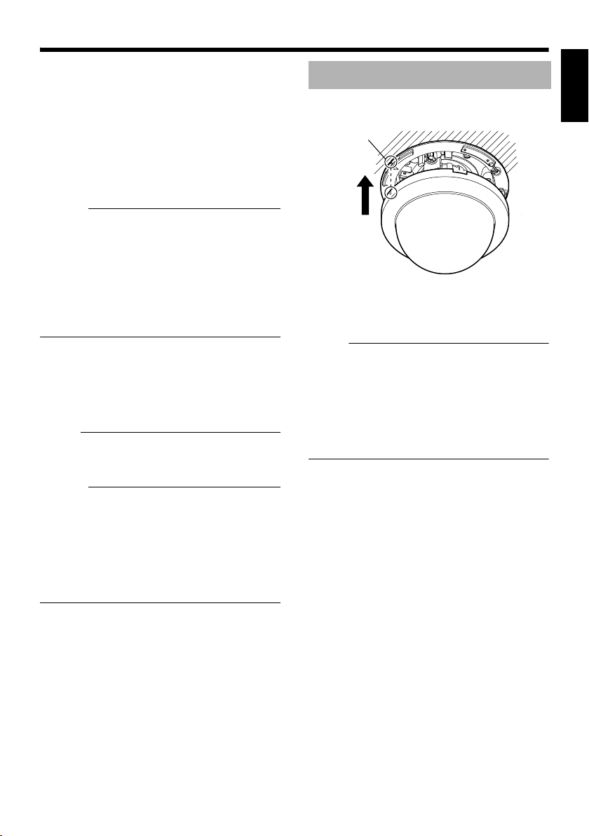
䡵 Mounting
1.Align the secured outer case with the
position alignment mark of the camera.
e :
● Make sure that the cables are not caught in
the outer case.
2.Turn the camera in the clockwise
direction.
T Check that the ○ mark can be seen. (Refer
to the diagram below)
3.Tighten the Camera Fastening Screws
and secure the camera.
Position
alignment
mark
1
2
Camera
Fastening
Screw
T Check
ENGLISH
6.Wind the waterproof tape. (A Pg. 26)
4
5
Solder or crimp
Insulation tape
Wind the waterproof
tape.
6
3
䡵 Image adjustment
When the camera is mounted, adjust the image
settings while looking at the actual image.
(A Pg.27 AImage adjustmentB)
䡵 Mounting the Dome Cover
After the image adjustment is completed, mount
the dome cover.
Installation is complete when the dome cover is
mounted.
(A Pg.29 AMounting the Dome CoverB)
E-21
Page 22
Setup
Not
Mounting the Camera
(continued)
Mount by allowing the cable to exit from the side
You can also mount the camera on a ceiling or
wall by pulling the cables horizontally instead of
drilling a hole.
The basic mounting method is the same as
eMounting the camera directly on a ceiling or
alongside a wallf (A Pg. 20).
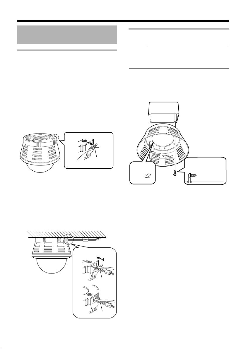
1.Remove the lid of the cable ejector hole
and divide the dotted line section of the lid
with a longnose pliers.
1
Divide
Cable ejector hole
2.Mount the outer case on the ceiling or
wall.
3.Pull out the cables from the cable ejector
hole.
4.Connect the cables. (A Pg. 20)
5.Close the lid of the cable ejector hole.
2
Mounting the camera to the electrical box
e :
● Before mounting the camera to electrical
boxes, please refer to local building codes for
box type to use for low-voltage wiring.
䡵 Connecting
1.Align (j) with the shooting direction when
mounting the outer case to the electrical box
Outer case
UP
FRONT
Align with shooting direction
mounting screws
Less than 3 mm
2.Follow steps 2. to 6. of AMount by allowing
the cable to exit from the sideB [Connection]
(A Pg. 20)
5
E-22
Page 23

䡵 Mounting
Attach the camera to the outer case that has
been fastened to the electrical box.
1.Follow steps 2. to 6. of AMount by allowing
the cable to exit from the sideB [Connection]
(A Pg. 20)
䡵 Image Adjustment
After mounting is completed, adjust the images
while checking the actual image.
(A Pg.27 AImage adjustmentB)
ENGLISH
E-23
Page 24
Setup
Not
Power Connection
Electricity can be supplied to this product either
by using the PoE or connecting to the DC12 V
power supply.
䢇 When electricity is supplied to the camera,
the status indicator blinks, and turns off when
startup is complete.
e :
● Make sure to select only one mode of
electrical supply. Connecting the power cable
and the LAN cable for the PoE at the same
time may result in failure or malfunction of the
camera.
Using the PoE
Connect to a device that supports PoE and
supply electricity from the LAN cable.
What is PoE (Power over Ethernet)?
This is a function that enables operation of a
LAN equipment without a power cable by
supplying power simultaneously with the data
using a LAN cable.
Connect to PoEcompatible device
Memo :
● For details on the connection method and
cable type, please refer to ALAN Cable
ConnectionB (A Pg. 26).
E-24
Page 25
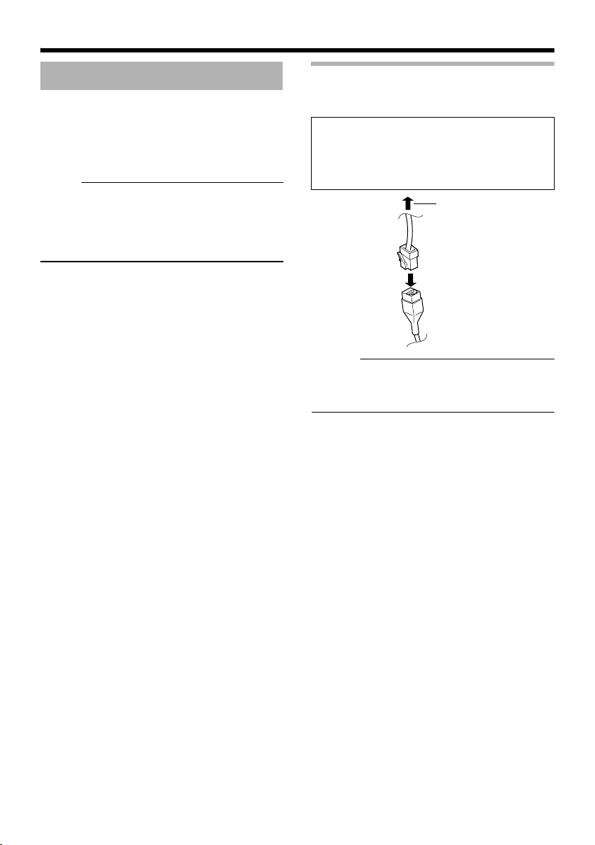
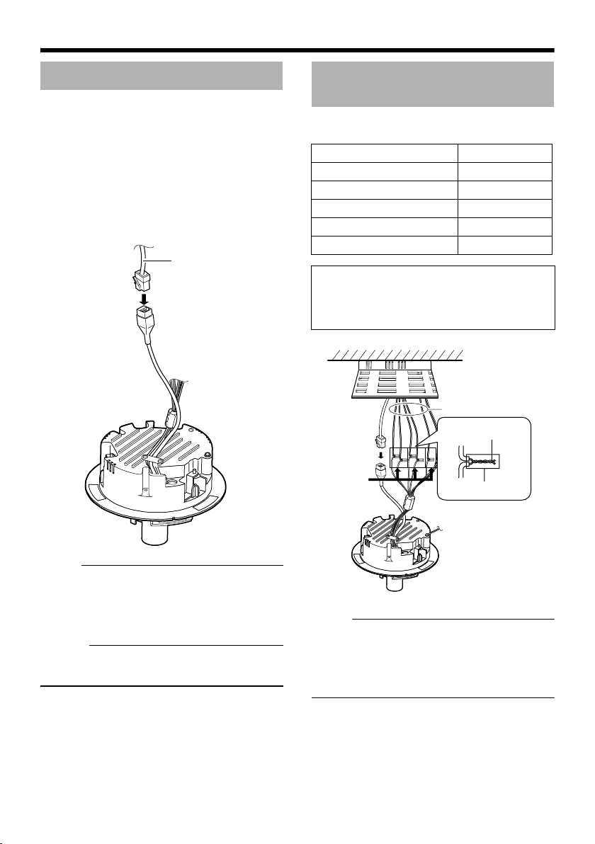
Connecting to the DC12 V power supply
Not
Connect this product to the DC12 V power
supply when not using the PoE.
Connect the polarity correctly.
Red : DC12V+
Black : DC12V-
e :
● Make sure to select only one mode of
electrical supply. Connecting the power cable
and the LAN cable for the PoE at the same
time may result in failure or malfunction of the
camera.
Power cable
Red: DC12 V+
Solder or
crimp
Insulation tape
Wind the
waterproof
tape.
Black: DC12 V-
Solder or
crimp
Insulation tape
Warning
The rated power of this product is DC12 V.
Make sure to use it with the correct voltage.
Supplying a power different from the rated
value may result in failures and in the worst
scenario, smoking and fire.
Memo :
● In a system where multiple units of VN-
C215V4U are used, turn on the power of only
1 unit to configure the IP address settings via
the Internet Explorer. Upon doing so, turn on
the power of the second unit and configure
accordingly. Configure the camera settings
using the same procedure.
● Whenever duplication of IP addresses
occurs, check that there is only one VNC215V4U under the same LAN environment
and wait for at least 10 minutes. Access to
VN-C215V4U may be denied unless you
restore the power supply of all network
devices under the same LAN environment.
● To use AA-P700 in the power supply unit,
connect one unit of this product. Also refer to
the AA-P700 instruction manual.
ENGLISH
Memo :
About the power cable
● When using 2-core VVF (Vinyl-insulated
vinyl-sheath cable), the connection distance
is as follows: (Reference value)
Maximum
extension (m)
Conductor
Diameter (mm)
40 120 190
R1.0 and
above
R1.6 and
above
R2.0 and
above
E-25
Page 26
Setup
Not
Not
LAN Cable Connection
Connect the camera to a hub or computer using
a LAN cable.
䡵 When connecting to a hub
Make use of a straight cable.
䡵 When connecting to a computer
Make use of a Cross Over cable.
LAN cable
Alarm Input/Output Cable Connection
Connect the alarm input/output cables with
external devices such as a sensor, buzzer, etc.
Signal name Cable color
Alarm input 1 Pink
Alarm input 2 Blue
Alarm output 1 Orange
Alarm output 2 Yellow
GND Brown
Cable to use
● Length of 50 m or shorter
● UL1007, UL1015 or equivalent products
● AWG#22 - AWG#18 or equivalent products
Alarm input/output cables
Solder or crimp
Wind the
waterproof
tape.
Insulation tape
e :
● Cross cables cannot be used with some
computer models. When connecting VNC215V4U directly to a computer, make sure
to check the computer’s LAN specifications in
advance.
Memo :
● Make use of a Category 5 (or higher) cable in
the case of 100BASE-TX.
E-26
e :
● Noises from an external source may cause
malfunctions even when the cable used is
shorter than 50 m. In this case, use a
shielded cable or move the cable away from
the noise source.
Page 27
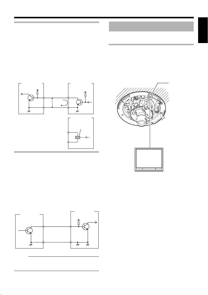
Alarm Input
Not
S
Connect this terminal to sensor devices, such as
an infrared sensor, door sensor, metal sensor,
manual switch, etc.
䡵 Input requirements
● No-voltage relay NPN open collector input
● Polarity of input detection can be selected
using a software
● Make/Break (500 ms and above)
● Circuit current at low level: 0.3 mA
● Applied voltage at high level: 3.3 V
Camera unit
DC3.3 V
Input 1
R
or Input 2
3.3 V
GND
(Alarm input equivalent circuit)
OUT
0.3 mA
GND
OUT
ensor
example (1)
VCC
R
Sensor
example (2)
Relay switch etc.
Image adjustment
When the camera is mounted, adjust the image
settings while looking at the actual image.
Mounting the test monitor
Connect the [MONITOR] terminal of the camera
to the test monitor to adjust the camera shooting
direction, field angle and focus.
T When configuring, turn on the power of the
camera.
[MONITOR]
terminal
ENGLISH
GND
Alarm Output
Connect this terminal to annunciating devices,
such as annunciators, indicators, lights, buzzers,
etc.
䡵 Output requirements
● Equivalent to NPN open collector output (Set
the output put logic via the Internet Explorer)
● Allowable applied voltage: DC12 V and below
● Allowable inflow current: 50 mA
● Momentary (100 ms - 5000 ms) output
(Set time via the Internet Explorer )
Camera unit
Output 1
or Output 2
GND
(Alarm output equivalent circuit)
IN
GND
e :
● Connect the GND cable of this camera to the
GND of the annunciating device.
annunciating
devices
DC 12 V
R
75 K terminated
Test monitor
E-27
Page 28
Setup
Not
Not
I
E
S
C
S
Image adjustment
(continued)
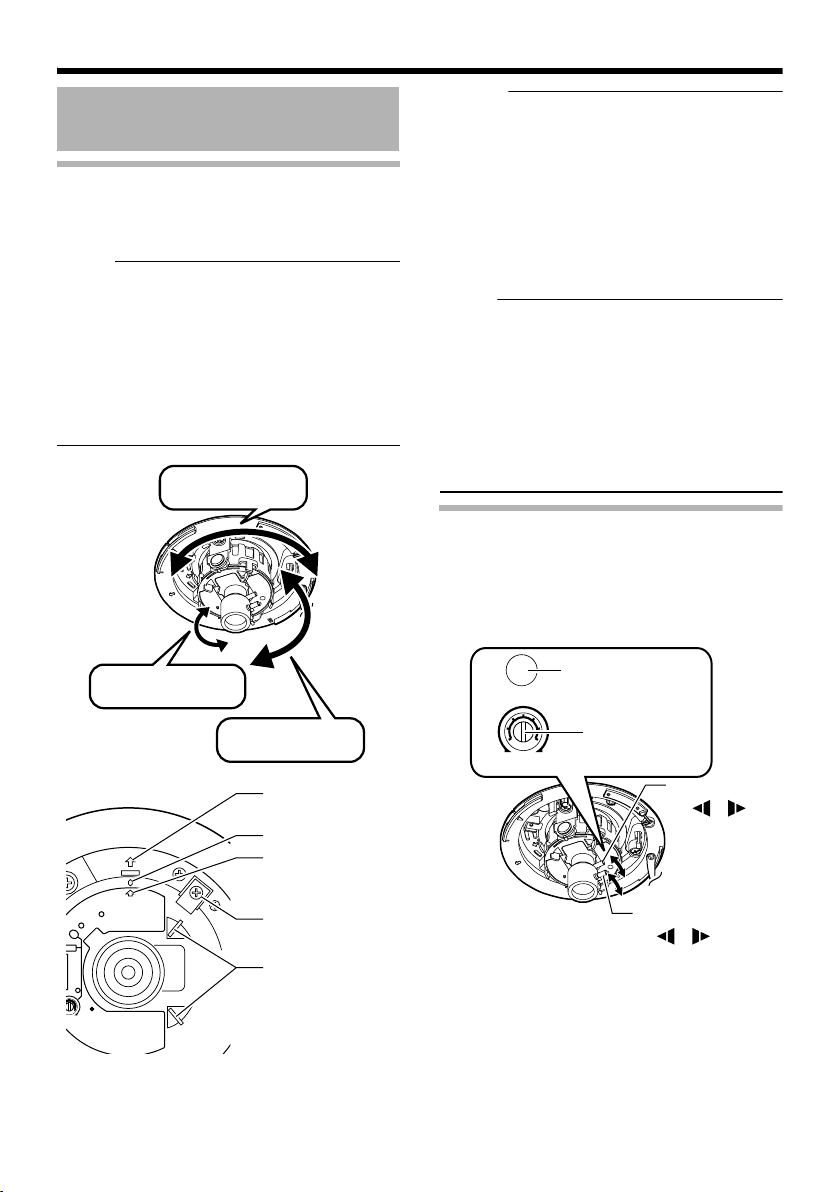
Adjusting the camera shooting direction
This camera can be adjusted for pan, tilt and
rotation. Adjust the direction and face the
camera towards the object.
e :
● Make sure you touch the metal surface of the
[MONITOR] terminal to release the static
electricity in your body before adjusting the
camera shooting direction.
● Make sure that the pan fastening screw is
loosened before adjusting the camera
shooting direction. The lens section may be
damaged if you operate it without loosening
the pan fastening screw.
Pan: ±175 ⬚
Rotation: ±175 ⬚
Memo :
● Rotate both pan and rotation ±175 ⬚ from the
positions aligned with the camera imaging
direction mark, pan center mark and rotation
center mark. Make sure you hold the rotation
claps and adjust the rotation without holding
the lens section.
● After adjusting the field angle, tighten and
secure the tilt fastening screw and pan
fastening screw so that the field angle will not
be misaligned when using the camera in
locations with vigorous vibrations. (A Pg. 12)
e :
● Moving the camera when it has exceeded the
adjustment range may cause its performance
to deteriorate.
● As the tilt and rotation range of this camera is
wide, part of the camera may be reflected in
the shooting screen depending on the field
angle and direction.
● Do not hold the lens section when adjusting
the camera direction. The lens section may
be damaged if you apply force to it.
Adjusting field angle, focus and
brightness
Once you have decided the shooting direction,
you can adjust the field angle, focus and
brightness.
Focus adjustment
FOCUS ADJUST
button
SPOT
ADJ
ADJ
E
H
RIS
VEL
E-28
Tilt: ±80 ⬚
Imaging Direction
mark
Pan center mark
Rotation center
mark
Pan fastening screw
:Be sure to loosen it
before adjustment.
Rotation Knob
:Make sure you hold
and turn this knob when
adjusting the rotation.
Iris level
LH
IRIS
LEVEL
adjustment dial
Zoom adjustment ring
W T
Focus adjustment ring
N F
Page 29
Field angle adjustment
Not
Not
Loosen the fastening screw of the zoom
adjustment ring, move the ring horizontally and
adjust the image size.
Focus adjustment
Press the focus adjustment button. The Iris will
open for approximately 30 seconds. Loosen the
fastening screw of the focus adjustment ring,
move the ring horizontally and adjust the focus.
Mounting the Dome Cover
After all settings are complete, mount the dome
cover.
Position alignment
mark
ENGLISH
Memo :
● Repeat EField angle adjustmentF and EFocus
adjustmentF 2 to 3 times and configure the
settings.
After adjustment is complete, tighten and
secure the respective fastening screws.
● Pressing the focus adjustment button
automatically activates the electronic shutter.
The screen may flicker but this is not a
malfunction.
Brightness adjustment
Normally, adjustment is not required. If
necessary, adjust the Iris level.
To darken : Anti-clockwise direction (towards L)
To brighten : Clockwise direction (towards H)
e :
● For adjusting the brightness, do not conduct
it within 30 seconds after pressing the focus
button.
Memo :
● When adjusting the iris level, set the AGC
function to AOffB. Otherwise, when the level
is turned too far toward L, the AGC function
activates increasing sensitivity and the
picture may look uneven.
For AAGC function settingsB, please refer to
the [INSTRUCTIONS] (pdf) in the supplied
CD-ROM.
1.
1.Mount the dome cover.
Align the camera with the position alignment
mark on the dome cover and push in the
dome cover to mount.
e :
● Push in the dome cover until you hear a click
sound. Check that it has been securely
mounted. Insecure mounting may cause the
camera to fall or interfere with the LED
(Status, Link, Act) display.
● When the cover is removed again after
mounting the dome cover, adjust the field
angle.
E-29
Page 30
Setting
Network Requirements
● Ensure that there is sufficient network
bandwidth for the data volume to be sent out
by VN-C215V4U.
● Data volume to be sent by VN-C215V4U
varies with the settings and number of
distributions.
● The maximum bit rate from VN-C215V4U is
about 9 Mbps.
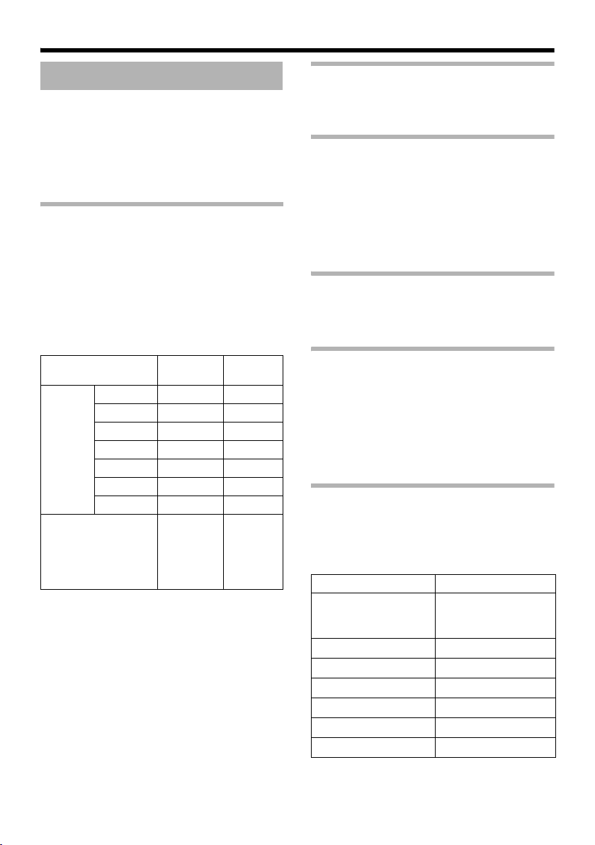
Estimation of total bit rate
The JPEG file size per frame varies with the
encoding settings as well as input video signals.
The following table may be used as a reference.
When VFS is selected, the quantization table
during JPEG encoding will be maintained and
the file size will increase/decrease according to
the input signals. When AFS is selected,
encoding will be performed such that the
average size of multiple JPEG images is the
target file size.
Picture Quality
Control Method
VFS
(Variable
File Size)
AFS
(Average File Size)
1 (High) 80 KB 27 KB
2 60 KB 20 KB
3 40 KB 13 KB
4 (Medium)
5 25 KB 8 KB
6 20 KB 7 KB
7 (Low) 15 KB 5 KB
VN-C215V4U accepts requests from up to a
maximum of 5 clients. In addition, it also allows
transmission of 1 multicast stream. The total
frame rate refers to the sum of these frame rates.
For example, when 10 fps is requested by 2
clients, and in addition multicast is transmitted at
a rate of 10 fps, the total frame rate will be:
10 + 10 + 10 = 30 fps
If the JPEG file size per frame is 30 KB, then the
total bit rate will be:
30 KB x 30 fps = 900 KB/s = Approx. 7.2
Mbps
VGA File
Size
30 KB 10 KB
Selection
may be
made from
the range
between 10
and 100 KB
QVGA
File Size
Selection
may be
made from
the range
between 3
and 33 KB
Insufficient network bandwidth
When there is insufficient bandwidth, the
number of JPEG frames (frame rate) that the
client can acquire will decrease.
Network Delay
When the client acquires JPEG via TCP, VNC215V4U will send out data while checking the
ACK from the client at the same time. For
networks with considerable delay, data cannot
be sent out until ACK is received, and therefore
the frame rate will drop.
Drop of frame rate due to network delay can be
eliminated by sending data via multicast.
Network Jitter
When there is considerable network jitter, delay
time may be prolonged and the image frame rate
may drop.
Packet Loss
When acquiring images from VN-C215V4U via
TCP, packet loss may be recovered by
resending by TCP. When there is considerable
delay during resending, however, missing data
may occur and the image frame rate may drop.
When packet loss occurs during multicast
sending from VN-C215V4U, the image frame
rate may drop.
List of protocols and port numbers used
by VN-C215V4U
VN-C215V4U uses the protocols and port
numbers listed below. Ensure that these ports
are allowed through the firewall when a firewall
is to be installed.
Protocol/Port No. Purpose of Use
TCP/80 JPEG acquisition,
Web Settings page,
API
TCP/20, 21 FTP
TCP/25 Mail delivery
TCP/User Setting No. Alarm sending
UDP/User Setting No. Alarm sending
UDP/User Setting No. Multicast sending
UDP /123 SNTP
E-30
Page 31

Not
Not
IP Address Settings
Setting IP address with the default VNC215V4U settings
There are 2 methods to set the IP address when
VN-C215V4U is in its default settings.
(A) Assigning an IP address to VN-C215V4U
from the DHCP server
(B) Assigning a static IP address to VN-
C215V4U
䡵 (A) Assigning an IP address from the
DHCP server
● VN-C215V4U is set to ADHCP EnableB (the
DHCP client function is ON) by default. To
assign an IP address from DHCP server,
connect VN-C215V4U to LAN with DHCP
server, and turn on VN-C215V4U. Allowing
the DHCP server to assign the same IP
address to VN-C215V4U every time eases
access to VN-C215V4U.
● For details on IP addresses assigned to VNC215V4U, please consult your network
administrator.
● You can look up the IP address of VNC215V4U using the [Search Tool] in the
attached CD-ROM.
For details, please refer to the AReadmeB file
in the attached CD-ROM.
e :
● Set the DHCP server such that constant
IPaddress is assigned to VN-C215V4U
based on the MAC address of VN-C215V4U.
Access by clients can fail if the above setting
is not performed.
䡵 (B) Assigning a static IP address
䢇 System configuration required for setting
IP address
VN-C215V4U is set to ADHCP EnableB (the
DHCP client function is ON) by default. Start VNC215V4U in LAN without DHCP server. After
DHCP timeout, VN-C215V4U starts with the
following IP address.
IP address : 192.168.0.2
Subnet mask : 255.255.255.0
Default gateway : None
Memo :
● To set a static IP address for VN-C215V4U,
connect VN-C215V4U, switching hub and
computer for setting using a straight LAN
cable of Category 5 and above.
䢇 Set up the computer for setting the IP
address.
● Minimum computer specifications for
setting
OS : Windows XP (Professional
or Home Edition) (SP2)
Web browser : Internet Explorer Version 6.0
e :
● When setting the IP address for VN-
C215V4U, do so by using a network that is
made up only of VN-C215V4U, the computer
for setting and the switching hub.
● Using a hub connected to other network
devices can cause problems.
ENGLISH
E-31
Page 32

Setting
Not
IP Address Settings
(continued)
䢇 IP Address setting at the computer
Set the computer to an IP address that enables communication with VN-C215V4U.
1.Click [Start]
● Select in the order of [Control Panel]-[Network Connection]-[Local Area].
2.The computer with which Internet Explorer is launched automatically selects the connected
network
● Right-click and select [Properties].
● Check to ensure that the [Client for Microsoft Networks] and [Internet Protocol(TCP/IP)] check
boxes are selected.
3.Select [Internet Protocol(TCP/IP)] and click [Properties].
4.Set the IP address
A
Select [Use the following IP adress].
B
Set the [IP Address]. (For example, use
192.168.0.100 when VN-C215V4U is in its
default settings)
Memo :
● Make sure that you take note of the original
IP address before altering.
e :
● When setting, ensure that a duplicate IP
address is not used within the same
network environment.
5.Click [OK] on the [Local Area Connection Properties] screen
E-32
C
Set [Subnet Mask] to a value that is
appropriate for the setting operation. Clarify
with the network administrator if you have any
queries.
(Use 255.255.255.0 when the camera is in its
default settings)
D
When a [Default Gateway] is present, make use
of the IP address (e.g., 192.168.0.254).
E
Click [OK].
Page 33

䢇 Changing the IP address using the Internet Explorer
1.Launch the Internet Explorer on the computer
2.When proxy setting is enabled in the Internet Explorer, follow the steps below to disable the
proxy of the Internet Explorer
● Select in the order of [Tools]-[Internet Options...]-[Connections]-[LAN Setting], followed by
deselecting the check for [Use a proxy server for your LAN] in [Proxy Server] of the [Local Area
Network(LAN)Settings] window.
Deselect the check
3.If Active scripting of the Internet Explorer is not set to AEnableB, follow the steps below to
enable it
● Select [Trusted sites] under [Tools]-[Internet Options...]-[Security]. Upon doing so, the [Sites...]
button directly below becomes active. Click on this button and deselect the check for [Require
server verification(https:) for all sites in this zone] in the displayed window. Next, add VNC215V4U web site to the zone.
Example: http://192.168.0.2
ENGLISH
● Next, select [Trusted sites] under [Tools]-[Internet Options...]-[Security], and press the [Custom
Level] button. Select [Enable] under [Scripting]-[Active scripting] of the [Security Settings]
window that has been opened.
Select [Enable]
E-33
Page 34

Setting
IP Address Settings
(continued)
䢇 Changing the IP address using the Internet Explorer (continued)
4.Launch the Internet Explorer
Enter the following IP address in the address field.
A
http://192.168.0.2
Click [Go].
B
Memo :
● If the proxy server setting in Internet Explorer is enabled, you may not be able to specify the IP
address directly. In this case, change the proxy settings of the Internet Explorer.
● After the Security Warning screen appears, press the [OK] button to proceed.
5.Enter the user name and password (login as an administrator)
A
Enter the user name.
VN-C215
This is set to AadminB by default.
Enter the password.
B
This is set to Avn-c215B by default.
Click [OK].
C
Memo :
● After the Security Alarm screen appears, press the [Yes] button to proceed.
E-34
Page 35

6.The top page of VN-C215V4U appears
7.The Basic page with the IP address settings appears
Click on [Network], followed by [Basic]
on the next submenu.
A
Set the [IP Setting] item to [DHCP
Disable].
B
Enter the values you wish to specify in
[IP Address], [Subnet Mask] and
[Default Gateway].
ENGLISH
C
Click [OK].
A confirmation screen appears. Press the [OK] button. The VN-C215V4U restarts using the new IP
address. It takes about 1 minute for the camera to reboot.
Memo :
● Access from this computer may fail when the IP address of VN-C215V4U is changed. To enable
access to VN-C215V4U from the same computer, alter the IP address at the computer accordingly.
E-35
Page 36

Setting
IP Address Settings
(continued)
When the IP address of VN-C215V4U is
known
When the IP address of VN-C215V4U is known,
it can be changed by using Internet Explorer on
the computer to access the built-in web page of
VN-C215V4U.
T Please refer to the ASetting Using Internet
ExplorerB of the [INSTRUCTIONS] (pdf) in
the supplied CD-ROM.
When the IP address of VN-C215V4U is
unknown
Changing of settings by accessing via a
computer is not possible when the IP address of
VN-C215V4U is unknown.
In this case, you can know the IP address using
the following method.
● The attached CD-ROM comes with a search
tool. Using this tool enables you to look up
VN-C215V4U within the LAN.
For details on the search tool, please refer to
the AReadmeB file in the attached CD-ROM.
E-36
Page 37

Operation
Operation of Built-in Viewer
Using the built-in viewer enables display of a
series of images, one-shot recording of images
and receiving of alarm information.
⽧Setting Up the Internet Explorer (A Pg. 38)
⽧Installing the built-in viewer
(A Pg. 40)
⽧Screen Configuration of Built-in Viewer
(A Pg. 41)
⽧Quitting the Built-in Viewer (A Pg. 42)
⽧Shortcut for Built-in Viewer (A Pg. 43)
● For ABuilt-in Viewer SettingsB please refer
to the [INSTRUCTIONS] (pdf) in the
supplied CD-ROM.
ENGLISH
E-37
Page 38

Operation
Operation of Built-in Viewer
(continued)
Setting Up the Internet Explorer
1.Launch the Internet Explorer on the computer
2.When proxy setting is enabled in the Internet Explorer, follow the steps below to disable the
proxy of the Internet Explorer
● Select in the order of [Tools]-[Internet Options...]-[Connections]-[LAN Setting], followed by
deselecting the check for AUse a proxy server for your LANB in [Proxy Server] of the [Local Area
Network(LAN)Settings] window.
Deselect the check
E-38
Page 39

3.If Active X controls and plug-ins of the Internet Explorer is disabled, follow the steps below
to enable it
● Click [Trusted sites] under [Tools]-[Internet Options...]-[Security]. Upon doing so, the [Sites...]
button directly below becomes active. Click on this button and deselect the check for [Require
server verification(https:) for all sites in this zone] in the displayed window. Next, add the IP
address of VN-C215V4U. If the setting is factory default, add the following web site to the zone.
http://192.168.0.2
● Click [Trusted sites] under [Tools]-[Internet Options...]-[Security]. Select the [Custom Level]
button and open the [Security Settings] window. From the opened window, set all the items in
[Active X controls and plug-ins] to [Enable].
ENGLISH
4.If the pop-up block function of the Internet Explorer is enabled, follow the steps below to
disable it
T The built-in viewer cannot be used when the pop-up block function is AEnableB.
● Selecting [Tools]-[Pop-up Blocker]-[Turn Off Pop-up Blocker] permits all sites.
● To allow only specific sites such as VN-C215V4U, select [Tools]-[Pop-up Blocker]-[Turn On Pop-
up Blocker], followed by selecting [Tools]-[Pop-up Blocker]-[Pop-up Blocker Settings] that
becomes active, and open the [Pop-up Blocker Settings] window. In the opened window, add the
address of VN-C215V4U as an allowed web site address.
5.When plug-in tools such as the Yahoo or Google toolbar are included in the Internet
Explorer, disable the pop-up block function of these plug-in tools as well
E-39
Page 40

Operation
Operation of Built-in Viewer
(continued)
Installing the built-in viewer
1.Enter the URL of the built-in viewer in the address field of Internet Explorer
For example, if the IP address of VN-C215V4U is 192.168.0.2, enter as follows:
http://192.168.0.2/cgi-bin/c215viewing.cgi
Enter the URL of the built-in viewer of this camera.
A
(The default URL is http://192.168.0.2/cgi-bin/
c215viewing.cgi)
http://192.168.0.2/cgi-bin/c215viewing.cgi
2.Enter the user name and password
VN-C215
B
Enter the user name.
A
This is set to AadminB by default.
B
Enter the password.
This is set to Avn-c215B by default.
C
Click [OK].
Select [Go]
3.The viewer is installed and launched
E-40
Page 41

Screen Configuration of Built-in Viewer
Not
● VN-C215V4U is set to encode at 15 fps by default.
ENGLISH
A
B
C
D
E
A Alarm Appears blinking when alarm packets are sent from VN-C215V4U to the
computer.
The alarm will continue blinking until the auto clear operation of the
alarm is performed. Clicking the blinking button turns the light off.
B Display Size Switches the display size.( VGA or QVGA)
C Pause Pauses/Resumes playback of images.
D Capture Captures the currently displayed image on the computer.
Images captured will be stored as a JPEG file in the AC215_JPEGB
directory that is created under [My Document] of the computer. The file
name is made up of year/month/day, hour/minute/second and the
millisecond.
The time denoted by the file name is based on the time at the computer
and not the internal clock of VN-C215V4U.
This feature is unable to capture motion images.
E Setup Displays the setting window of the built-in viewer.
This setting screen is used to set the built-in viewer as a software on the
computer.
e :
● Settings on this setting screen are not applied as settings to the VN-
C215V4U unit.
T For details of the settings, please refer to the ABuilt-in Viewer
SettingsB of the [INSTRUCTIONS](pdf) in the supplied CD-ROM.
E-41
Page 42

Operation
Operation of Built-in Viewer
(continued)
Quitting the Built-in Viewer
To quit, press the [Close] button at the top right of the window.
Click [Close].
● To restart the built-in viewer, launch the Internet Explorer and enter the URL of the built-in viewer in
the address field.
For example, if the IP address of VN-C215V4U is 192.168.0.2, enter as follows:
http://192.168.0.2/cgi-bin/c215viewing.cgi
● After the Security Warning screen appears, press the [OK] button to proceed.
E-42
Page 43

Shortcut for Built-in Viewer
Creating a shortcut for the built-in viewer on the
Desktop screen of the computer saves you the
trouble of having to enter the URL in the Internet
Explorer.
Create the shortcut using the procedures below.
1.Launch the Internet Explorer
2.Right-click on Internet Explorer on the
screen and select [Create Shortcut]
Click the [OK] button on the confirmation
screen and a shortcut will be created on the
Desktop screen.
3.Right-click on the shortcut icon on the
Desktop screen and select Properties
The setting screen appears.
4.Enter the URL of the built-in viewer in the
URL field
For example, if the IP address of VNC215V4U is 192.168.0.2, enter as follows:
http://192.168.0.2/cgi-bin/c215viewing.cgi
5.Click the [OK] button to end
Clicking on the shortcut created will help to
save you the trouble of having to enter the
URL in the Internet Explorer.
Memo :
● Before starting up the built-in viewer using
the shortcut, close all Internet Explorer
windows. Starting up the built-in viewer using
the shortcut while leaving other Internet
Explorer windows opened may result in
malfunction of the built-in viewer.
ENGLISH
E-43
Page 44

Others
Specifications
Camera Unit
Image pickup
device
Effective pixels : Approx. 380,000 pixels
[Monitor Output]
Monitor output x 1 (75, 1 Vp-p)
Horizontal
resolution
Minimum object
illumination
Video S/N ratio : 50 dB (typ. 50 %, AGC
[Network Output]
Image
compression
format
Frame size : 640 ⳯ 480 320 ⳯ 240
Network interface : RJ-45 100BASE-TX/
LAN Specifications
Compliant with IEEE802.3, IEEE802.3u and
IEEE802.3af
Communication
protocol
: 1/4 inch Interline transfer
CCD
768 (H) ⳯494 (V)
: 540 TV lines (typ.)
: 2.5 lx (typ. 50 %, F1.3,
wide-angle lens, AGC ON)
0.75 lx (typ. 25 %, F1.3,
wide-angle lens, AGC ON)
1.4 lx (typ. 50 %, F1.3,
wide-angle lens, Easy Day
and Night ON)
0.4 lx (typ. 25 %, F1.3,
wide-angle lens, Easy Day
and Night ON)
OFF)
: JPEG
10BASE-T/FULL/HALF/
auto negotiation supported
: TCP/IP, UDP, HTTP, FTP,
ICMP, ARP, RTP, DHCP,
SNTP, SMTP, IGMP
General
Alarm Input : No-voltage a contact input,
Alarm Output : NPN open collector output
Internal memory : 8 MB
Supply voltage : DC12 V or DC -48 V
Consumption
current
Ambient
temperature
Ambient humidity : 35 % RH to 85 % RH
Mass : Approx. 750 g
NPN open collector input,
low level, latch/momentary
(500 ms and above) (Circuit
current during low level: 0.3
mA; Applied voltage during
high level: 3.3 V)
(Allowable applied voltage:
12 V; Allowable inflow
current: 50 mA)
(Supply by power feeding
device that supports Power
over Ethernet)
: 0.5 A (Max.)
: -10 I to 50 I (operation)
0 I to 40 I
(recommended)
(without condensation)
Attachments/Accessories
Start-up Guide ................................................. 1
CD-ROM.......................................................... 1
Warranty Card ................................................. 1
Service Information Card................................. 1
Template.......................................................... 1
E-44
Page 45

Dimension [Unit: mm(inches)]
71 (2-13/16)
58 (2-5/16)
55 (2-3/16)
Ǿ116 (4-9/16)
133 (5-1/4)
Ǿ120 (4-3/4)
83,5 (3-5/16)
46 (1-13/16)
89 (3-1/2)
6 (1/4)
4,5 (3/16)
Ǿ145 (5-3/4)
Ǿ145 (5-3/4)
89 (3-1/2)
SR55 (2-1/8)
4-Ǿ4,5 (3/16)
SR55 (2-1/8)
⽧When cover is attached
⽧When embedded
ENGLISH
T Specifications and appearance of this unit and related products are subject to change for product
improvement without prior notice.
E-45
Page 46

FIXED IP DOME CAMERA
VN-C215V4U
DEUTSCH
SCHNELLEINSTIEG
Danke, dass Sie sich für den Kauf dieses
Produktes von JVC entschieden haben.
Bitte lesen Sie diese Anleitung sorgfältig
durch, bevor Sie das Gerät in Betrieb
nehmen, denn nur so können Sie seine
Leistungsmerkmale optimal nutzen.
Page 47

Einleitung
Sicherheitshinweise
ACHTUNG:
UM DER GEFAHR VON BRÄNDEN UND
ELEKTRISCHEN SCHLÄGEN
VORZUBEUGEN, DARF DIESES GERÄT
WEDER DEM REGEN NOCH HOHER
FEUCHTIGKEIT AUSGESETZT
WERDEN.
ACHTUNG
Um elektrische Schläge zu vermeiden, das
Gehäuse nie öffnen. Im Innern befinden sich
keine Teile, die vom Benutzer gewartet
werden können. Überlassen Sie die Wartung
qualifiziertem Service-Personal.
Benutzerinformationen zur Entsorgung alter Geräte
[Europäische Union]
Dieses Symbol zeigt an, dass das elektrische bzw. elektronische Gerät nicht
als normaler Haushaltsabfall entsorgt werden soll. Stattdessen sollte das
Produkt zur fachgerechten Entsorgung, Weiterverwendung und
Wiederverwertung in Übereinstimmung mit der Landesgesetzgebung einer
entsprechenden Sammelstelle für das Recycling elektrischer und
elektronischer Geräte zugeführt werden.
Die korrekte Entsorgung dieses Produkts dient dem Umweltschutz und
verhindert mögliche Schäden für die Umwelt und die menschliche
Gesundheit, welche durch unsachgemäße Behandlung des Produkts
Hinweis:
Dieses Symbol
ist nur in der
Europäischen
Union gültig.
Wegen Entwurfsmodifikationen ist es
möglich, dass die in dieser
Anleitung gegebenen Daten ohne vorherige
Ankündigung geändert
werden.
auftreten können. Weitere Informationen zu Sammelstellen und dem
Recycling dieses Produkts erhalten Sie bei Ihrer Gemeindeverwaltung,
Ihrem örtlichen Entsorgungsunternehmen oder in dem Geschäft, in dem Sie
das Produkt gekauft haben.
Für die nicht fachgerechte Entsorgung dieses Abfalls können gemäß der
Landesgesetzgebung Strafenausgesprochen werden.
(Geschäftskunden)
Wenn Sie dieses Produkt entsorgen möchten, besuchen Sie bitte unsere
Webseite www.jvc-europe.com, um Informationen zur Rücknahme des
Produkts zu erhalten.
[Andere Länder außerhalb der Europäischen Union]
Wenn Sie dieses Produkt entsorgen möchten, halten Sie sich dabei bitte an
die entsprechenden Landesgesetze und andere Regelungen in Ihrem Land
zur Behandlung elektrischer und elektronischer Geräte.
Sehr geehrter Kunde, sehr geehrte Kundin,
dieses Gerät stimmt mit den gültigen
europäischen Richtlinien und
Normen bezüglich elektromagnetischer
Verträglichkeit und elektrischer
Sicherheit überein.
Die europäische Vertretung für die Victor
Company of Japan, Limited ist:
JVC Technology Centre Europe GmbH
Postfach 100552
61145 Friedberg
Deutschland
Erklärung zum Rauschen (für die
Bundesrepublik Deutschland):
Maschinenlärminformations-Verordunung 3.
GPSGV, 06.01.2004: Der höchste
Schalldruckpegel beträgt 70 dB(A) oder
weniger gamäß EN ISO 7779
G-2
Page 48

● Installations- und Montagearbeiten sind von
qualifiziertem Fachpersonal entsprechend
den geltenden Richtlinien durchzuführen.
● Installations- und Montagearbeiten sind in
Übereinstimmung mit dem National Electrical
Code, ANSI/NFPA 70, durchzuführen (nur in
den USA anwendbar).
● Dieses Gerät ist mit einem 12-VGleichstromnetzteil zu betreiben.
●
Das 12-V-Gleichstromnetzteil muss folgenden
Anforderungen genügen: Nur Klasse 2 (nur in
den USA anwendbar). Nur potenzialfreie
Spannungsquelle (in Europa sowie weiteren
Ländern).
●
Ggf. in diesem Handbuch aufgeführte
Alarmeingänge und -ausgänge wurden von
den UL nicht auf ihre Tauglichkeit als
Einbruchsalarmsysteme geprüft (nur für USA).
● In bestimmten Ländern ist der Einbau von
Kameras unter Umständen gesetzlich nicht
zulässig. Weitere Informationen erhalten Sie
bei Ihrem JVC-Händler.
● Die Decke, an der die Kamera montiert
werden soll, muss so ausgelegt sein, dass
sie das Kameragewicht tragen kann. Kann
die Decke das Gewicht der Kamera nicht
tragen, so sind in jedem Fall vor Montage der
Kamera Verstärkungen zu installieren.
● Das Etikett mit den Kenndaten befindet sich
seitlich an der Kameraeinheit.
●
Wenn Montageschrauben und -muttern nicht
ausreichend angezogen sind, kann die
Kameraeinheit herabfallen. Stellen Sie aus
diesem Grund sicher, dass diese Schrauben
und Muttern ausreichend stark angezogen sind.
●
Wir übernehmen keine Haftung für Schäden an
der Kamera, wenn diese durch ein Herabfallen
aufgrund einer unvollständigen Installation infolge
der Nichtbeachtung der Montageanweisungen
verursacht wurden. Bitte gehen Sie bei der
Installation der Kamera mit Sorgfalt vor.
● Installieren Sie die Kamera nicht in der Nähe
von Beleuchtungseinrichtungen, die hohe
Temperaturen erzeugen (z. B. Scheinwerfer).
Andernfalls besteht die Möglichkeit von
Fehlfunktionen und Feuergefahr.
● Bevor Sie eine wichtige Aufzeichnung
durchführen, sollten Sie in jedem Fall
Testaufnahmen erstellen, um sich zu
vergewissern, dass eine normale
Aufzeichnung möglich ist.
● Wir werden für eine aufgrund von
Fehlfunktionen der Videokamera, des
Video- oder Festplattenrecorders und/oder
der Aufnahmekassette fehlgeschlagene
Aufzeichnung von Inhalten oder sich hieraus
ergebenden Verlusten und Folgeschäden
keine Entschädigung leisten.
● Berühren Sie vor der Ausrichtung der
Kamera die Metallfläche des [MONITOR]Anschlusses mit der Hand, um sich zu erden
(d. .h eine ggf. vorhandene statische
Aufladung Ihres Körpers zu entladen).
Dieses Handbuch beschreibt die
grundlegende Verwendung der VNC215V4U.
Weitere Informationen zur Verwendung der
VN-C215V4U finden Sie unter
AEINLEITUNGB.
Aktuelle Informationen entnehmen Sie der
Datei AReadmeB auf der beiliegenden CDROM.
● Die beiliegende CD-ROM enthält die PDFDateien [EINLEITUNG] und [API Guide]
sowie das [Search Tool].
● Um PDF-Dateien anzeigen zu können,
muss der AAdobe ReaderB auf dem
Computer installiert sein.
DEUTSCH
G-3
Page 49

Einleitung
Wichtigste Leistungsmerkmale
䡵 Hohe Bildqualität
Die Kameraeinheit der VN-C215V4U basiert auf
einem 1/4"-CCD mit 380.000 Bildpunkten und
gewährleistet so eine hohe Bildqualität.
䡵 Großer Erfassungsbereich
Die Kamera bietet einen großen Einstellbereich
für den zu erfassenden Bereich und ist mithilfe
eines Drehjustiermechanismus auch zur
Wandmontage geeignet.
䡵 Keine Sichtbehinderung
Der kuppelförmige Aufbau ermöglicht eine
einfache Verwendung, ohne dass es zu
Behinderungen durch die Kamera selbst kommt.
䡵 Deckeneinbau ohne Halterung
Die Kameraeinheit kann in die Decke
eingelassen werden, ohne dass hierfür
Einbauhalterungen erforderlich wären.
䡵 Leistungsstarkes Varioobjektiv
Die detailgetreue Überwachung wird ermöglicht
durch das integrierte Varioobjektiv mit 3,6x-Zoom.
䡵 Nachtüberwachung
Die VN-C215V4U wird mit einer Funktion zur
Leuchtkraftpegelabsenkung ausgeliefert. Diese
als „Easy Day and Night“ bezeichnete Funktion
schaltet bei schwacher Beleuchtung
automatisch in einen hochempfindlichen
Schwarzweißmodus um.
䡵 Unterstützung von PoE (Power over
Ethernet)
Die VN-C215V4U unterstützt PoE (IEEE802.3af)
und ermöglicht die Stromversorgung über ein
LAN-Kabel.
䡵 Implementierung der
Höchstdatenrate
Die Datenübertragung ist in VGA-Größe bei
einer Datenrate von 30 Bildern/s möglich.
䡵 Integrierter Webserver
Die Einstellungen können mit dem Internet
Explorer vorgenommen werden.
䡵 Multicast-Unterstützung
Die VN-C215V4U bietet
Multicastingunterstützung, was den
gleichzeitigen Versand von Bilddaten an
mehrere PCs im Netzwerk ohne Verringerung
der Bildrate ermöglicht.
䡵 Bewegungserkennung
Diese Funktion ermöglicht die Ausgabe von
Alarmsignalen bei Erkennung von Bewegungen
innerhalb eines bestimmten Bildbereichs.
Über den Alarmeingang können auch vor bzw.
nach dem Auslösezeitpunkt aufgezeichnete
Bilder via FTP gesendet werden.
䡵 Integrierter Viewer
Die Anzeige der Überwachungsbilder mithilfe
eines Computers ist nach Installation dieses
integrierten Viewers auf dem Computer möglich.
䡵 HTTP-basiertes API
Bestandteil der VN-C215V4U ist auch ein HTTPbasiertes API (Anwendungsschnittstelle). Diese
Funktionalität ermöglicht die Einstellung und
Steuerung über das Netzwerk.
Hinweise zu diesem Handbuch
䡵 Verwendete Symbole
Hinweis : Hinweise zum Betrieb des
beschriebenen Produkts.
Erinnerung : Referenzangaben zu
Funktionen, Beschränkungen
usw. des beschriebenen
Produkts.
A : Querverweis auf andere Seiten
oder Themen in diesem
Handbuch.
䡵 Zum Inhalt dieses Handbuchs
● © JVC. Alle Rechte vorbehalten.
Vervielfältigung oder Nachdruck dieses
Handbuchs – auch auszugsweise – sind
ohne Genehmigung streng untersagt.
● Windows ist ein eingetragenes
Warenzeichen der Microsoft Corporation in
den USA.
● Alle übrigen in diesem Handbuch
aufgeführten Produktnamen sind
Warenzeichen oder eingetragene
Warenzeichen der jeweiligen
Unternehmen. Bitte beachten Sie, dass
Symbole wie 姠, 姞, 姝 usw. in diesem
Handbuch nicht aufgeführt sind.
● Anschauungsbilder, technische Daten und
andere in diesem Handbuch vermittelte
Informationen können im Sinne einer
stetigen Produktverbesserung ohne
vorherige Ankündigung geändert werden.
G-4
Page 50

Inhaltsverzeichnis
Einleitung
Sicherheitshinweise ............................ 2
Wichtigste Leistungsmerkmale ........... 4
Inhaltsverzeichnis ............................... 5
Betriebsbedingungen .......................... 6
Warnhinweise ..................................... 6
Bedienelemente und Funktionen ........ 8
Merkmale .......................................... 12
Einrichtung
Gesamtablauf ................................... 14
Montage der Kamera ........................ 14
Bevor Sie mit der Montage
beginnen ................................. 14
Auswählen der Montagemethode
Deckenmontage ............................ 15
Direktaufbau der Kamera auf die
Decke oder eine Seitenwand
Montage mit seitlichem
Kabelaustritt ........................... 20
Montage der Kamera an einer
Anschlussdose ....................... 20
Stromversorgung .............................. 22
Verwenden von PoE ..................... 22
Anschluss an 12-V-
Gleichstromnetzteil ................. 23
Anschließen des LAN-Kabels ........... 24
Anschließen von Alarmeingangs- und
Alarmausgangskabeln ............... 24
Bildjustierung .................................... 25
Kuppelabdeckung montieren ............ 27
.... 15
.... 18
Einstellungen
Netzwerkspezifikation .......................28
IP-Adresseinstellungen .....................29
TInformationen zum Themenbereich
ASetting Using Internet ExplorerB
entnehmen Sie dem Dokument
[EINLEITUNG], welches als
PDF-Dokument auf der beiliegenden
CD-ROM zu finden ist.
Betrieb
Betrieb des integrierten Viewers ....... 35
Einrichten des Internet Explorer .... 36
Installieren des integrierten
Viewers ................................... 38
Bildschirmkonfiguration des
integrierten Viewers ................ 39
Beenden des integrierten Viewers
Verknüpfung zum integrierten
Viewer ..................................... 41
Sonstiges
Technische Daten .............................42
DEUTSCH
... 40
G-5
Page 51

Einleitung
Betriebsbedingungen
䡵 PC-Anforderungen
Betriebssystem : Windows XP Home Edition/
CPU : Pentium 4, 1,5 GHz (oder
Speicher : > 1 GB
Festplattenspeicher
Grafikkarte : 1024 ⳯ 768 Bildpunkte
Webbrowser : Internet Explorer Version 6.0
䡵 LAN-Umgebung
● 10BASE-T/100BASE-TX-Netzwerk,
Anbindung über einen IEEE 802,3kompatiblen Switching-Hub.
● IEEE802,3af-kompatibler Switching-Hub bei
Verwendung von PoE.
● IGMPv2-kompatibles Netzwerk bei
Verwendung von Multicasts.
Erinnerung:
● Die aufgeführten PC-Spezifikationen sind
lediglich Richtlinien für einen möglichst
störungsfreien Betrieb der Anwendung. Ihre
Beachtung gewährleistet den Betrieb als
solchen unter Umständen nicht.
● Je nach Einsatzbedingungen laufen
Anwendungen unter Umständen auch dann
nicht einwandfrei, wenn die genannten
Anforderungen erfüllt werden.
XP Professional einschl. SP2
besser)
: mind. 20 Mbyte freier
Speicherplatz
(min.), True Color (24- oder
32-Bit-Farben)
Warnhinweise
Wartung und Betriebsumgebung
䢇 Diese Kamera ist für den Einsatz im
Innenbereich vorgesehen. Ein Einsatz in
Außenbereichen ist nicht möglich.
䢇 Lagern Sie die Kamera nicht in den
nachfolgend aufgeführten Umgebungen.
Andernfalls können Fehlfunktionen oder
Ausfälle auftreten.
● An Orten, deren Temperatur außerhalb
des zulässigen Bereichs von –10 I bis
+50 I liegt.
● An Orten, deren relative Luftfeuchtigkeit
außerhalb des zulässigen Bereichs von
35 bis 85 Prozent liegt.
(Kondenswasserbildung vermeiden.)
● In der Nähe von Geräten, die starke
Magnetfelder erzeugen, wie z. B.
Transformatoren oder Motoren.
●
In der Nähe von Geräten, die Funkwellen
aussenden, wie z. B. Sender und Mobiltelefone.
● An Orten, an denen in hohem Maße
Staub oder Sand vorhanden sind.
●
An Orten, an denen das Gerät übermäßigen
Erschütterungen ausgesetzt ist.
● An Orten, an denen Feuchtigkeit auftreten
kann (z. B. in der Nähe eines Fensters).
● An Orten, an denen Dampf oder Öl
auftreten (z. B. Küchen).
●
An Orten, an denen Strahlungen, Röntgenstrahlen
oder ätzende Gase austreten können.
䢇 Die Verwendung dieses Produkts und der
daran angeschlossenen Kabel an Orten, an
denen starke elektrische oder magnetische
Wellen erzeugt werden (z. B. in der Nähe
eines Radio- oder TV-Geräts, eines
Transformators, eines Monitors usw.) kann
Störungen und Rauschen in den Bildern
hervorrufen oder die Farben beeinträchtigen.
䢇
Installieren Sie die Kamera nicht an Orten, an
denen kühle Luft zirkuliert, z. B. in der Nähe des
Luftauslasses einer Klimaanlage. Drastische
Temperaturänderungen können zu einem
Beschlagen der Kuppelabdeckung führen.
䢇 Installieren Sie das Gerät nicht an Orten, an
denen ein Wärmestau entstehen kann.
Dieses Produkt leitet überdies selbst Wärme
über die Oberfläche der Haupteinheit ab.
Montieren Sie es deswegen nicht an Orten,
an denen ein Wärmestau entstehen kann (z.
B. direkt an Wänden).
G-6
Umgang mit dem Gerät
䢇 Blockieren Sie keinesfalls die
Lüftungsöffnungen des Geräts.
Eine unzureichende Wärmeabfuhr kann zu
Fehlfunktionen des Produkts führen. Achten
Sie darauf, die Lüftungseinrichtungen des
Produkts nicht zu blockieren.
Page 52

Sonstiges
䢇
Diese Kamera hat eine integrierte AGC-Schaltung.
Wenn AGC die Einstellung
die Empfindlichkeit an dunklen Orten automatisch,
wodurch das Bild auf dem Bildschirm körnig
wirken kann. Dies ist keine Fehlfunktion.
䢇
Wenn White Balance die Einstellung CAutoD hat,
können sich je nach Objektbedingungen die
Bildfarben von den tatsächlichen Objektfarben
unterscheiden. Es handelt sich dabei um eine
Folge der Betriebsweise der Weißabgleichslogik.
Dies ist jedoch keine Fehlfunktion.
䢇
Wenn Sie ein sehr helles Objekt (z. B. eine
Lampe) aufnehmen, kann es vorkommen, dass an
den Bildrändern senkrechte weiße Linien
(Schlieren) oder Schleier erscheinen. Das ist eine
Eigenschaft des CCDs und keine Fehlfunktion.
䢇
Die elektronische Verschlusszeit der Kamera ist
werksseitig auf 1/60 Sekunde eingestellt. Um
ein Flackern bei Leuchtstofflampen (außer bei
Wechselbeleuchtung) an einem Ort zu
verhindern, an dem eine Netzfrequenz von 50
Hz verwendet wird, setzen Sie die
Verschlusszeit auf 1/100 Sekunde. (Hierbei
verringert sich die Empfindlichkeit geringfügig.)
䢇
Wenn Easy Day and Night die Einstellung COnD
hat, wird das Bild an dunklen Orten
schwarzweiß. Wird nun die Empfindlichkeit
erhöht, dann kann der Bildschirm körnig
erscheinen, und die Anzahl weißer Punkte kann
ebenfalls zunehmen. Ferner werden, wenn
Farbbilder auf schwarzweiß umgestellt werden,
helle Bereiche des Bildes betont und sind
aufgrund dessen unter Umständen schwer zu
sehen. Dies ist jedoch keine Fehlfunktion.
䢇
Das Bild kann verzerrt werden oder vermehrt
Rauschen aufweisen, wenn die Netzspannung
für einen kurzen Moment unterbrochen wird
oder aufgrund von Blitzschlag, Einschalten
einer Klimaanlage o. ä. abfällt.
䢇
Der Drehwinkel dieses Produkts ist
werksseitig auf Weitwinkel eingestellt, um
Weitwinkelgeräte zu unterstützen. Wenn der
Objektivzoom weit ist und der Neigungswinkel
bei ca. ±80
Kuppelabdeckung bei entsprechendem
Weitwinkel unter Umständen im Bild. Passen
Sie den Feldwinkel in solchen Fällen bei
Bedarf an. (
䢇 Bei Verwendung von Multicasts müssen Sie
einen IGMPv2-kompatiblen Netzwerk-Switch
einsetzen.
䢇 Die Betriebsspannung kann an dieses
Produkt wahlweise über PoE oder durch
Anschluss an das 12-V-Gleichstromnetzteil
angelegt werden. Wählen Sie in jedem Fall
nur eine Art der Spannungsversorgung. Der
gleichzeitige Anschluss des Netzkabels und
des LAN-Kabels für PoE kann zu Ausfällen
oder Fehlfunktionen der Kamera führen.
(A S. 22, 23)
⬚
liegt, spiegelt sich die
A
S. 27)
COnD
hat, erhöht sich
Urheberrechtliche Hinweise
䢇 Um urheberrechtlich geschütztes Video- oder
Audiomaterial kopieren, modifizieren,
übertragen o. ä. zu dürfen, ist grundsätzlich
eine entsprechende Genehmigung
erforderlich, sofern man nicht selbst Inhaber
der Urheberrechte ist oder eine solche
Genehmigung bereits vorliegt.
Nicht genehmigte Kopie, Modifikation,
Übertragung usw. urheberrechtlich
geschützten Materials kann einen Verstoß
gegen das Urheberrecht darstellen, aus dem
sich Schadensersatzansprüche gegenüber
dem Benutzer ergeben können. Bei
Verwendung urheberrechtlich geschützten
Video- oder Audiomaterials ist die
Lizenzvereinbarung des urheberrechtlich
geschützten Materials in jedem Fall zu
beachten.
Bestehen Rechte am zu kopierenden Motiv
oder gibt es entsprechende Rechteinhaber,
dann ist zur Aufnahme des Motivs oder der
Verwendung (Verarbeitung) solcher
Aufnahmen unter Umständen eine
Genehmigung erforderlich. Beachten Sie in
jedem Fall die Lizenzbestimmungen.
Wartung
䢇 Schalten Sie das Gerät vor Wartungsarbeiten
ab.
䢇 Wischen Sie das Gerät mit einem trockenen,
weichen Tuch ab.
Eine Reinigung mit Verdünnungsmittel oder
Reinigungsbenzin kann die Oberfläche
angreifen oder anlaufen lassen.
Hartnäckigen Schmutz mit einem in Wasser
verdünnten Neutralreiniger entfernen und
anschließend mit einem trockenen Tuch
nachwischen.
Energieeinsparung
䢇 Wenn Sie das Gerät für längere Zeit nicht
benutzen, schalten Sie es ab, um Risiken zu
vermeiden und Strom zu sparen.
DEUTSCH
G-7
Page 53

Einleitung
Bedienelemente und Funktionen
Kameraeinheit
I
A
B
C
D
E
Montageöffnung (oval) ⳯ 4
A
Verwenden Sie diese Öffnungen zur Montage
an der Anschlussdose.
(A S. 20)
B Montageöffnung (rund) ⳯ 4
Verwenden Sie diese Öffnungen zur Wandbzw. Deckenmontage. (A S. 18, 20)
C Außengehäuse
Dieses verwenden Sie in den folgenden Fällen:
● zur direkten Montage der Kamera an Wand
oder Decke (A S. 18)
● zur Montage an einer Anschlussdose
(A S. 20)
D Kuppelabdeckung
Die Kuppelabdeckung ist zerbrechlich.
Behandeln Sie sie deswegen mit Umsicht.
E Innenkuppel
Entfernen Sie diese Innenkuppel vor Montage
der Kamera und führen Sie eine Einstellung des
Bildwinkels durch. (A S. 16, 18)
H
B
A
G
F
Status
Link
Act
F Funktionsprüfungsanzeige
[Status]-Anzeige (Statusanzeige)
Diese Anzeige blinkt nach dem Einschalten.
Nach der Initialisierung der Kamera schaltet sie
sich ab. Wenn die Anzeige weiterblinkt, während
die Kamera verwendet wird, überprüfen Sie die
Kamera oder das angeschlossene Gerät.
[Link]-Anzeige (Verbindungsanzeige)
Diese Anzeige leuchtet, wenn die Kamera mit
dem Netzwerk verbunden ist.
[Act]-Anzeige (Aktivitätsanzeige)
Diese Anzeige leuchtet bei laufenden Aktivitäten
wie dem Versand oder Empfang von Daten.
G Kabelaustritt
Diese Öffnung dient dem seitlichen
Herausziehen von Kabeln, wenn kein Loch in die
Decke gebohrt werden soll.
(A S. 20)
G-8
Page 54

Kameraeinheit (innen)
T Nachfolgende Abbildung zeigt das Gerät nach Entfernen von Kuppelabdeckung, innerer Abdeckung
und Außengehäuse.
Hinweise zum Entfernen dieser Komponenten finden Sie unter A S. 15 CDeckenmontageD,
Schritte 3. bis 5.
Objektivbereich
(A S. 11)
W
J
K
L
M
N
H Stromversorgung/Alarmkabel
(A S. 22, 24)
Signalbezeichnung Kabelfarbe
Alarmeingang 1 Violett
Alarmeingang 2 Blau
Alarmausgang 1 Orange
Alarmausgang 2 Gelb
GND Braun
12-V-Gleichstromnetzteil (+) Rot
12-V-Gleichstromnetzteil (–) Schwarz
Anmerkung:
● PoE nicht gemeinsam mit dem 12-VGleichstromnetzteil verwenden. Der
gleichzeitige Anschluss kann zu Ausfällen
oder Fehlfunktionen führen.
I [10BASE-T/100BASE-TX(PoE)]-Anschluss
für LAN-Anbindung (RJ-45)
(A S. 24)
J Schlaufe
Verbindet die Kameraeinheit mit der
Kuppelabdeckung.
Rückseite der Kameraeinheit
V
U
T
P
Y
MAC address
S
R
X
Q
P
O
K Befestigungsschrauben (× 3)
Dieser Schraubenkopf der
Deckenmontagehalterung Q ist bei Montage der
Kamera an der Decke zu verwenden.
L [RESET]-Taste (Rückstelltaste)
Diese Taste dient dem Neustarten der Kamera.
Betätigen Sie die Taste und lassen Sie sie
innerhalb von fünf Sekunden los, um die Kamera
neu zu starten. Die Neuinitialisierung der
Kamera dauert etwa eine Minute. Während des
Neustarts ist die [RESET]-Taste deaktiviert.
Anmerkung:
● Wenn Sie die [RESET]-Taste mindestens
fünf Sekunden lang betätigen, schaltet die
Kamera in den Wartungsprüfmodus. Aus
diesem Grund sollten Sie diese Taste nicht
fünf Sekunden oder länger betätigen.
M [MONITOR]-Anschluss (Cinchbuchse)
(A S. 25)
N Kameraeinheit
O
Befestigungshaken für das Sicherheitskabel
P Sicherheitskabel (im Lieferumfang
enthalten) und zugehörige Schraube
Montieren Sie die Kameraeinheit N und das
Außengehäuse C nur mit der
Befestigungsschraube
O
für das Sicherheitskabel.
DEUTSCH
G-9
Page 55

Einleitung
Bedienelemente und
Funktionen (fortsetzung)
Kamerainneres
Objektivbereich
(A S. 11)
W
J
K
L
M
N
Q
Deckenmontagehalterung (× 3)
Diese Halterung wird bei der Deckenmontage
der Kamera verwendet. (A S. 15)
R Befestigungsschraube für die Kamera
Mit dieser Schraube befestigen Sie die
Kameraeinheit N am Außengehäuse C.
Hinweise zum Entfernen unter (A S. 16, 18)
S Schwenkfeststellschraube
Lösen Sie diese Schraube in jedem Fall, bevor
Sie die Justierung vornehmen. Ziehen Sie die
Schraube nur an, wenn Sie die Kamera an Orten
mit stärkeren Erschütterungen verwenden, um
eine Fehlausrichtung der Kameraaufnahme zu
verhindern. (A S. 26)
T Bildrichtungsmarkierung
Installieren Sie die Kamera so, dass der Pfeil in
die Aufnahmerichtung weist.
U Drehungsregler
Dieser Regler steuert die Objektivbereiche und
stellt die Bildneigung ein. (A S. 26)
V Drehungsmittenmarkierung
(A S. 26)
Rückseite der
Kameraeinheit
V
U
T
P
Y
MAC address
S
R
X
Q
P
O
W Neigungsfeststellschraube
Ziehen Sie diese Schraube an, nachdem Sie
den Feldwinkel eingestellt haben, sodass eine
Fehlausrichtung des Feldwinkels vermieden
wird, wenn Sie die Kamera an Orten mit
stärkeren Erschütterungen verwenden.
(A S. 26)
X Montageöffnung und -schraube für
Sicherheitskabel
Diese Komponenten dienen der Montage des an
der Decke befestigten Sicherheitskabels.
(Das Sicherheitskabel ist nicht im Lieferumfang
enthalten.)
Y [MAC address]-Angabe (MAC-Adresse)
Die MAC-Adresse ist die eindeutige physische
Adresse des Produkts. Diese Adresse kann
nicht verändert werden.
G-10
Page 56

Objektivbereich
SPOT
Z
a
Z
[FOCUS ADJ]-Einstelltaste (Scharfstellung)
FOCUS ADJ
IRIS ADJ
FOR SERVICE
L
IRIS
LEVEL
H
Mit dieser Taste stellen Sie die Scharfstellung
ein.
Betätigen Sie die Taste, um die Objektivblende
für 30 Sekunden zu öffnen. Dies erleichtert die
Scharfstellung, da die Feldtiefe verringert wird.
(A S. 27)
Erinnerung:
● Wenn Sie die Fokustaste betätigen, wird der
elektronische Verschluss automatisch
aktiviert. Der Bildschirm kann dabei flackern.
Dies ist keine Fehlfunktion.
a [IRIS LEVEL] Justierrad für die
Blendenöffnung
Mit diesem Rad stellen die Sie Blendenöffnung
eines Objektivs mit Automatikblende ein.
Diese Einstellung ist normalerweise nicht
erforderlich. Nehmen Sie sie bei Bedarf vor,
wenn die Bedingungen des Motivs es erfordern.
Dunklere
Einstellung
Hellere
Einstellung
: Drehen gegen den Uhrzeigersinn
(Richtung L)
: Drehen im Uhrzeigersinn
(Richtung H)
b
c
Erinnerung:
● Nehmen Sie die Einstellung der
Blendenöffnung vor, nachdem Sie [AGC] auf
COffD gestellt haben. Informationen zur
Einstellung der AAGC-FunktionB finden Sie
unter [EINLEITUNG]. Die entsprechende
Datei finden Sie im PDF-Format auf der
beiliegenden CD-ROM.
● Wenn COffD nicht gewählt ist, aktiviert eine
Bewegung des Rades in Richtung L die
AGC-Funktion. Die Empfindlichkeit der
Kamera erhöht sich, und die Bildqualität wird
körnig.
b Fokusring
Bewegen Sie den Ring horizontal, um die
Scharfstellung zu justieren.
(A S. 27)
c Zoomring
Bewegen Sie den Ring horizontal, um den
Feldwinkel zu justieren. (A S. 27)
DEUTSCH
G-11
Page 57

Einleitung
Merkmale
Überwachung mit dem integrierten
Viewer
Die VN-C215V4U wird mit einem integrierten
ActiveX-Viewer ausgeliefert.
Die Anzeige von VN-C215V4U-Bildern mithilfe
eines Computers ist nach Installation dieses
integrierten Viewers auf dem Computer möglich.
Angezeigte Bilder können auch auf der
Festplatte des Computers abgelegt werden.
CBetrieb des integrierten ViewersD (A S. 35)
VN-C215V4U
Netzwerk
Computer
Überwachung über Multicast
Die Überwachung mithilfe mehrere Computer
wird über Multicasts unterstützt.
Speichern von JPEG-Bildern auf dem
FTP-Server in regelmäßigen Abständen
JPEG-Bildern können in regelmäßigen
Abständen auf den FTP-Server hochgeladen
werden.
VN-C215V4U
Regelmäßiges Senden
der neuesten Bilder an
den FTP-Server
Netzwerk
Computer
Alarm
Zu den Merkmalen der VN-C215V4U gehören
eine Bewegungserkennung und zwei
Alarmsignaleingänge.
Durch Bewegungsmeldung oder ein
eingehendes Alarmsignal lassen sich Vorgänge
wie ein E-Mail-Versand,
die Übertragung von Meldungen via TCP/UDP
oder ein ausgehendes Alarmsignal auslösen.
Als Auslöser kann auch eine Kombination
eingehender Alarmsignale verwendet werden.
Die Installation eines FTP-Servers erlaubt das
Hochladen von Bildern vor und nach dem
Auslösezeitpunkt des Alarms auf den Server.
VN-C215V4U
G-12
IGMPv2-
kompatibles
Netzwerk
Computer
Computer
Computer
VN-C215V4U
Senden von Bildern
vor und nach dem
Auslösezeitpunkt
des Alarms
Alarmeinrichtung
Netzwerk
Computer
Page 58

Beschränkungen auf Clients
Die VN-C215V4U ist in der Lage, die
Bildaufzeichnung abhängig von der
angegebenen IP-Adresse zu gestatten oder
abzulehnen.
Steuerung über angepasste
Anwendungssoftware
Es sind ferner die folgenden
Einsatzmöglichkeiten möglich, wofür allerdings
die Entwicklung einer angepassten
Anwendungssoftware erforderlich ist, die die
Anwendungsschnittstelle (API) der VN-C215V4U
unterstützen muss.
Weitere Informationen entnehmen Sie dem [API
Guide] auf der beiliegenden CD-ROM.
● Überwachung über den Computer bei
gleichzeitiger Aufzeichnung von Bildern auf
die Festplatte.
● Aufzeichnung durch Änderung des
Bildformats oder der Bildrate bei
anliegendem Alarmsignal.
● Aufzeichnung von Typ und Zeitpunkt des
Alarmsignals auf den Computer.
● Weitere Informationen zur Verwendung der
VN-C215V4U entnehmen Sie dem
Dokument [EINLEITUNG], welches im
PDF-Format auf der beiliegenden CD-ROM
enthalten ist.
DEUTSCH
G-13
Page 59

Einrichtung
Gesamtablauf
Herstellen der Anschlussverbindungen und
Einrichten des Systems sind nachfolgend
beschrieben.
䢇 Stellen Sie sicher, dass Sie die
Metalloberfläche des [MONITOR]Anschlusses berühren, um sich zu erden
(d. h. die statische Elektrizität Ihres
Körpers abzuleiten). Andernfalls kann eine
solche statische Aufladung zu
Fehlfunktionen der Kamera führen.
Schritt 1
K
Schritt 2
K
Konfiguration (A S. 14)
Installieren Sie die Kamera und
konfigurieren Sie die
Bildeinstellungen.
Netzwerkeinstellungen
(A S. 28)
Konfigurieren Sie die
Netzwerkeinstellungen des
Computers und dieser Kamera.
Montage der Kamera
Bevor Sie mit der Montage beginnen
Anmerkung:
● Tragen Sie in jedem Fall eine Schutzbrille,
um Ihre Augen bei der Deckenmontage der
Kamera vor herabfallenden Gegenständen
zu schützen.
● Die Montage einer Deckeneinbauhalterung
(versenkte Halterung) ist in bestimmten
Ländern gesetzlich vorgeschrieben.
● Sollte dies in Ihrem Land der Fall sein, dann
stellen Sie sicher, dass die Einbauhalterung
fest installiert ist, bevor Sie die Kamera
montieren.
● Hinweise zur Installation der Einbauhalterung
finden Sie in der zugehörigen
Bedienungsanleitung.
● Weitere Informationen zur Einbauhalterung
erhalten Sie von JVC.
Versenkte
Einbauhalterung
Decke
Schritt 3
K
Schritt 4
G-14
Internet ExplorerEinstellungen
T Weitere Informationen
entnehmen Sie dem Dokument
[EINLEITUNG], welches als
PDF-Dokument auf der
beiliegenden CD-ROM zu
finden ist.
Betrieb des integrierten
Viewers
(A S. 35)
Bedienschritte wie das
Überwachen und das Speichern
eines Standbildes sind mit dem
integrierten Viewer möglich.
Page 60

Auswählen der Montagemethode
Die Vorgehensweise unterscheidet sich je nach
gewählter Montagemethode. Überprüfen Sie die
jeweiligen Komponenten vor Beginn der
Montage.
Anmerkung:
● Wenn Sie die Kamera mithilfe einer
Anschlussdose montieren wollen, wenden
Sie sich an Ihren Händler oder das für Sie
zuständige JVC-Kundendienstzentrum.
Montagemethode
䢇 Deckenmontage (A S. 15)
䢇 Direktaufbau auf die Decke oder eine
Seitenwand (A S. 18)
䢇 Montage durch horizontales Einziehen
der Kabel
(A S. 20)
䢇 Montage der Kamera an einer
Anschlussdose
(A S. 20)
Warnung
● Bei Montage der Kamera an eine Wand
oder Decke ist besondere Vorsicht
geboten. Die Montagearbeiten sind
ausschließlich von ausgebildeten
Montagefachkräften durchzuführen. Bei
unsachgemäßer Montage kann die Kamera
herabstürzen. Es besteht Unfall- und
Verletzungsgefahr.
● JVC übernimmt keine Haftung, wenn die
Kamera aufgrund unsachgemäßer
Montage unter Nichtbeachtung der
Montagebeschreibung herabstürzt. Gehen
Sie bei der Montage mit der erforderlichen
Sorgfalt vor.
● Um zu verhindern, dass die Kamera
herabstürzt, stellen Sie sicher, dass sie mit
einem Sicherheitskabel an einer stabilen
Stelle (Decke, Kabelkanal) befestigt ist.
● Achten Sie ferner auf Länge, Stärke,
Drahtkern und Material (Isolierungsqualität)
des zu verwendenden Sicherheitskabels.
● Wenn Montageschrauben und -muttern
nicht ausreichend angezogen sind, kann
die Kamera herabfallen. Stellen Sie aus
diesem Grund sicher, dass diese
Schrauben und Muttern ausreichend
angezogen sind.
● Installieren Sie die Kamera nicht in der
Nähe von Beleuchtungseinrichtungen, die
hohe Temperaturen erzeugen (z. B.
Scheinwerfer). Es besteht Ausfall- und
Feuergefahr.
Deckenmontage
T Die Stärke des Deckenmaterials sollte
zwischen 9,5 und 22 mm liegen.
䡵 Einrichtung
1.
Bohren Sie ein Loch in die Decke (R120 mm)
2.Ziehen Sie die Kabel aus der Decke.
Ziehen Sie Sicherheitskabel, LAN-Kabel,
Netzkabel und Alarmkabel aus der Decke. Diese
sind zuvor in der Decke zu verlegen. (Das
Sicherheitskabel ist nicht im Lieferumfang
enthalten.)
Anmerkung:
● Achten Sie ferner auf Länge, Stärke,
Drahtkern und Material (Isolierungsqualität)
des zu verwendenden Sicherheitskabels.
● Verwenden Sie zur Befestigung des
Sicherheitskabels an der Kamera einen Ring
mit einem Innendurchmesser zwischen R3,1
mm und R5,5 mm und einem
Außendurchmesser von R9 mm.
R120 mm
1
Sicherheitskabel
(nicht im
Lieferumfang
enthalten)
Netzkabel,
Alarmkabel
LAN-Kabel
3.Entfernen Sie die Kuppelabdeckung
Halten Sie den Kuppelring wie nachfolgend
abgebildet so fest, dass die Positionsmarkierung
zwischen Daumen und Zeigefinger liegt. Drehen
Sie den Kuppelring nun gegen den
Uhrzeigersinn, um ihn zu lösen.
Kuppelring
ca. 100 mm
2
Positionsmarkierung
DEUTSCH
G-15
Page 61

Einrichtung
Montage der Kamera
(fortsetzung)
Deckenmontage (fortsetzung)
4.Entfernen Sie die innere Kuppel.
Die innere Kuppel ist mit drei Bügeln befestigt.
Lösen Sie die innere Kuppel von den Bügeln.
5.Entfernen Sie das Außengehäuse.
(Das Außengehäuse wird für diese
Montagemethode nicht verwendet.)
A Lösen Sie die Befestigungsschrauben der
Kamera mit einem Schraubdreher.
B Drehen Sie die Kamera nun gegen den
Uhrzeigersinn und entfernen Sie das
Außengehäuse.
6.Nehmen Sie das Sicherheitskabel ab.
Entfernen Sie das an der Kamera befestigte
Sicherheitskabel.
7.Lösen Sie die Schwenkfeststellschraube.
Anmerkung:
● Wenn Sie die Kamera betreiben, ohne die
Schwenkfeststellschraube zu lösen, kann es
zu Schäden am Objektiv kommen.
Innenkuppel
䡵 Verbindungen
1.Befestigen Sie das Sicherheitskabel an
der Kamera. Dieses Kabel verbindet die
Kamera mit der Decke.
2.Schließen Sie das LAN-Kabel an.
(A S. 24)
3.Schließen Sie Netz- und Alarmkabel an.
(A S. 22, 24)
Erinnerung:
● Das Netzkabel darf nicht angeschlossen
werden, wenn PoE verwendet wird.
4.Bringen Sie das Isolierband auf.
5.Setzen Sie die Kamera in die
Deckenöffnung ein.
3
3
Löten oder crimpen
Isolierband
1
Sicherheitskabe
l (nicht im
Lieferumfang
enthalten)
Bringen Sie das
Isolierband auf.
2
4
5
G-16
B
4
Schwenkfeststellschraube
7
Befestigungsschraube
A
5
für die Kamera
6
Unterlegscheibe
Page 62

䡵 Montage
1.Richten Sie die Richtungsmarkierung (j)
in die Aufnahmerichtung aus und befestigen
Sie dann die Kamera.
2.Die Kamera muss an drei Stellen befestigt
werden.
A Drücken Sie mit einem
Kreuzschlitzschraubdreher den
Schraubenkopf der
Deckenmontagehalterung ein.
B Drehen Sie den weiterhin aufgesetzten
Schraubdreher um 90° im Uhrzeigersinn.
Wenn der Anschlag erreicht wird, ziehen Sie
den Schraubdreher ab.
C Die Deckenmontagehalterung ist nun in die
Decke eingelassen, und die Kamera sitzt
fest.
Erinnerung:
● Um die Kamera zu entfernen, drehen Sie die
drei Schraubköpfe der
Deckenmontagehalterung um 90° gegen den
Uhrzeigersinn.
䡵 Bildjustierung
Wenn die Kamera montiert ist, justieren Sie
unter Beobachtung des aufgezeichneten Bildes
die Bildeinstellungen.
(A S.25 CBildjustierungD)
䡵 Kuppelabdeckung montieren
Wenn die Bildjustierung abgeschlossen ist,
befestigen Sie die Kuppelabdeckung.
Nach Montage der Kuppelabdeckung ist die
Installation abgeschlossen.
(A S.27 CKuppelabdeckung montierenD)
DEUTSCH
1
T
P
U
FRON
In Aufnahmerichtung
B
A
2
G-17
Page 63

Einrichtung
B
A
C
4
5
7
5
5
6
Montage der Kamera (fortsetzung)
Direktaufbau der Kamera auf die Decke oder eine Seitenwand
Wenn Sie die Kamera an eine Wand montieren,
ersetzen Sie in der nachfolgenden Beschreibung
den Ausdruck „Decke“ durch „Wand“.
䡵 Einrichtung
1.
Bohren Sie ein Loch in die Decke (R35 mm)
Verwenden Sie zum Bohren des Lochs die
beiliegende Schablone.
2.Ziehen Sie Sicherheitskabel, LAN-Kabel,
Netzkabel und Alarmkabel aus der Decke.
Diese sind zuvor in der Decke zu verlegen.
(Das Sicherheitskabel ist nicht im
Lieferumfang enthalten)
Anmerkung:
● Achten Sie ferner auf Länge, Stärke,
Drahtkern und Material (Isolierungsqualität)
des zu verwendenden Sicherheitskabels.
● Verwenden Sie zur Befestigung des
Sicherheitskabels an der Kamera einen Ring
mit einem Innendurchmesser zwischen R3,1
mm und R5,5 mm und einem
Außendurchmesser von R9 mm.
B
Drehen Sie die Kamera nun gegen den
Uhrzeigersinn und entfernen Sie das Außengehäuse.
C Lösen Sie das Sicherheitskabel vom
Befestigungshaken
6.Lösen Sie die Schwenkfeststellschraube.
Anmerkung:
●
Wenn Sie die Kamera betreiben, ohne die
Schwenkfeststellschraube zu lösen, kann es zu
Schäden am Objektiv kommen.
7.
Konfigurieren Sie die Bildeinstellungen. (AS. 11)
Innenkuppel
Schwenkfeststellschraube
Befestigungsschraube
für die Kamera
R35 mm
1
Sicherheitskabel
(nicht im Lieferumfang
3.Entfernen Sie die Kuppelabdeckung.
Halten Sie den Kuppelring wie nachfolgend
abgebildet so fest, dass die Positionsmarkierung
zwischen Daumen und Zeigefinger liegt. Drehen
Sie den Kuppelring nun gegen den
Uhrzeigersinn, um ihn zu lösen.
4.Entfernen Sie die innere Kuppel.
Die innere Kuppel ist mit drei Bügeln befestigt.
Lösen Sie die innere Kuppel von den Bügeln.
5.Entfernen Sie das Außengehäuse.
A Lösen Sie die Befestigungsschrauben der
G-18
enthalten)
Netzkabel,
Alarmkabel
LAN-Kabel
Kuppelring
Positionsmarkierung
Kamera mit einem Schraubdreher.
2
ca. 100 mm
䡵 Verbindungen
1.Richten Sie die Richtungsmarkierung (j)
in die Aufnahmerichtung aus und befestigen
Sie dann das Außengehäuse auf der Decke.
Hinweise zu den Montageschrauben für
das Außengehäuse (nicht im Lieferumfang
enthalten):
●
Verwenden Sie einen Schraubenkopf mit
einem Durchmesser von weniger als 3 mm.
● Die Montageöffnung des Außengehäuses
hat einen Durchmesser von R 4,5 mm.
●
Verwenden Sie keine Senkschrauben.
● Wenn Sie einen Schlagschrauber
verwenden, ziehen Sie die Schrauben
zunächst nicht vollständig an. Führen Sie
den abschließenden Anzug stattdessen
mit der Hand durch. Andernfalls kann das
Außengehäuse beschädigt werden.
2.Ziehen Sie das zuvor in Schritt 4. gelöste
und entfernte Sicherheitskabel durch den
Befestigungshaken.
3.Befestigen Sie das Sicherheitskabel an
der Kamera. Dieses Kabel verbindet die
Kamera mit der Decke.
(Das Sicherheitskabel ist nicht im
Lieferumfang enthalten.)
Anmerkung:
● Ziehen Sie alle Schrauben fest an.
Andernfalls kann sich die Kamera lösen und
herabfallen.
Page 64

Montageschraube
des
Außengehäuses
< 3 mm
Zum
1
UP
FRONT
In Aufnahmerichtung
Sicherheitskabel
(nicht im
Lieferumfang
enthalten)
Von der
Decke
Befestigung
shaken
T Ausreichend
3
weit lösen
2
4.Schließen Sie das LAN-Kabel an.
(A S. 24)
5.Schließen Sie Netz- und Alarmkabel an.
(A S. 22)
Erinnerung:
● Das Netzkabel darf nicht angeschlossen
werden, wenn PoE verwendet wird.
䡵 Montage
1.Richten Sie das befestigte Außengehäuse
auf die Markierung der Kamera aus.
Anmerkung:
● Achten Sie darauf, dass sich die Kabel nicht
im Außengehäuse verfangen.
2.Drehen Sie die Kamera im Uhrzeigersinn.
T Vergewissern Sie sich, dass das Zeichen Åõ
sichtbar ist. (Siehe nachfolgende Abbildung.)
3.Ziehen Sie die
Kamerabefestigungsschrauben an und
befestigen Sie so die Kamera.
Positionsmarkierung
1
2
T Überprüfen
Befestigungsschraube
für die Kamera
DEUTSCH
6.Bringen Sie das Isolierband auf. (A S. 24)
5
Löten oder crimpen
4
Isolierband
Bringen Sie das
Isolierband auf.
6
3
䡵 Bildjustierung
Wenn die Kamera montiert ist, justieren Sie
unter Beobachtung des aufgezeichneten Bildes
die Bildeinstellungen.
(A S.25 CBildjustierungD)
䡵 Kuppelabdeckung montieren
Wenn die Bildjustierung abgeschlossen ist,
befestigen Sie die Kuppelabdeckung.
Nach Montage der Kuppelabdeckung ist die
Installation abgeschlossen.
(A S.27 CKuppelabdeckung montierenD)
G-19
Page 65

Einrichtung
Montage der Kamera
(fortsetzung)
Montage mit seitlichem Kabelaustritt
Sie können die Kamera auch an einer Decke
oder Seitenwand befestigen, indem Sie die
Kabel horizontal herausziehen, statt ein Loch zu
bohren.
Die Vorgehensweise zur Montage ist
grundsätzlich identisch mit der unter
eDirektaufbau der Kamera auf die Decke oder
eine Seitenwandf (A S. 18) beschriebenen
Methode.
1.Entfernen Sie die Abdeckung des
Kabelaustritts und trennen Sie den
unterbrochenen Bereich der Abdeckung mit
einer Spitzzange auf.
1
Auftrennen
Kabelaustritt
2.Montieren Sie das Außengehäuse an einer
Decke oder Seitenwand.
3.Ziehen Sie die Kabel aus dem
Kabelaustritt.
2
4.Schließen Sie die Kabel an (A S. 18)
5.Setzen Sie die Abdeckung des
Kabelaustritts wieder auf.
5
Montage der Kamera an einer Anschlussdose
Anmerkung:
● Vor der Montage der Kamera an eine
Anschlussdose beachten Sie bitte die
gültigen Baubestimmungen für
Anschlussdosen, die für
Niederspannungsinstallationen vorgesehen
sind.
䡵 Anschließen
1.Richten Sie die Markierung j bei der
Montage des Außengehäuses an der
Anschlussdose in die gewünschte
Aufnahmerichtung aus
Montageschrauben
UP
FRONT
In Aufnahmerichtung stellen
des
Außengehäuses
< 3 mm
2.Führen Sie die Schritte 2. bis 6. des
Abschnitts CMontage mit seitlichem
KabelaustrittD [Verbindungen] (A S. 18)
durch
G-20
Page 66

䡵 Montage
Montieren Sie die Kamera am Außengehäuse,
nachdem Sie dieses an der Anschlussdose
befestigt haben.
1.Führen Sie die Schritte 2. bis 6. des
Abschnitts CMontage mit seitlichem
KabelaustrittD [Verbindungen] (A S. 18)
durch
䡵 Bildjustierung
Wenn die Montage abgeschlossen ist, müssen
Sie die Bildjustierung mit optischer Kontrolle
vornehmen.
(A S.25 CBildjustierungD)
DEUTSCH
G-21
Page 67

Einrichtung
Stromversorgung
Die Betriebsspannung kann an dieses Produkt
wahlweise über PoE oder durch Anschluss an
das 12-V-Gleichstromnetzteil angelegt werden.
䢇 Sobald eine Spannungsquelle mit der
Kamera verbunden wird, blinkt die
Statusanzeige. Nach Abschluss der
Initialisierung erlischt die Anzeige.
Anmerkung:
● Wählen Sie in jedem Fall nur eine Art der
Spannungsversorgung. Der gleichzeitige
Anschluss des Netzkabels und des LANKabels für PoE kann zu Ausfällen oder
Fehlfunktionen der Kamera führen.
Verwenden von PoE
Schließen Sie die Kamera an ein Gerät an, das
PoE unterstützt, und richten Sie die
Stromversorgung über das LAN-Kabel ein.
Was ist PoE (Power over Ethernet)?
Hierbei handelt es sich um eine Funktion, die
den Betrieb von LAN-Geräten ohne Netzkabel
gestattet. Die Versorgungsspannung wird
gemeinsam mit den Daten über ein LANKabel bereitgestellt.
An PoE-kompatibles
Gerät anschließen
Erinnerung:
● Informationen zur Verbindungsmethode und
zum zu verwendenden Kabeltyp finden Sie
unter CAnschließen des LAN-KabelsD
(A S. 24).
G-22
Page 68

Anschluss an 12-V-Gleichstromnetzteil
Wenn Sie PoE nicht verwenden, schließen Sie
dieses Produkt an das 12-V-Gleichstromnetzteil
an.
Achten Sie beim Anschluss auf korrekte
Polarität.
Rot : DC12V+
Schwarz : DC12V-
Anmerkung:
● Wählen Sie in jedem Fall nur eine Art der
Spannungsversorgung. Der gleichzeitige
Anschluss des Netzkabels und des LANKabels für PoE kann zu Ausfällen oder
Fehlfunktionen der Kamera führen.
Netzkabel
Rot: DC12 V+Schwarz: DC12 V-
Löten oder
crimpen
Isolierband
Bringen Sie
das
Isolierband
auf.
Löten oder
crimpen
Isolierband
Warnung
Die Nennspannung dieses Produkts beträgt
12 V. Achten Sie auf korrekte
Spannungswerte.
Das Anlegen einer vom Nennwert
abweichenden Spannung kann zu Ausfällen
führen. Unter ungünstigsten Bedingungen
besteht Rauchentwicklungs- und Feuergefahr.
Erinnerung:
● Schalten Sie in einem Verbund mit mehreren
VN-C215V4U-Einheiten zunächst nur die
Stromversorgung einer Einheit ein und
konfigurieren Sie die IP-Adresseinstellungen
dann über den Internet Explorer. Danach
schalten Sie die zweite Einheit ein und
konfigurieren Sie entsprechend.
Konfigurieren Sie die Kameraeinstellungen
unter Verwendung derselben Methode.
● Sollten IP-Adressen doppelt auftreten, dann
vergewissern Sie sich, dass nur eine
VN-C215V4U in derselben LAN-Umgebung
vorhanden ist, und warten Sie mindestens
zehn Minuten. Der Zugriff auf die
VN-C215V4U kann verweigert werden, bis
Sie die Stromversorgung aller
Netzwerkgeräte in derselben LANUmgebung wiederhergestellt haben.
● Wenn Sie ein AA-P700 als Netzgerät
verwenden wollen, schließen Sie genau eine
Einheit dieses Produkts an. Weitere
Informationen entnehmen Sie dem
Bedienungshandbuch zum AA-P700.
DEUTSCH
Erinnerung:
Hinweise zum Netzkabel
● Wenn Sie zweiadriges VVF-Kabel (Kabel mit
Vinylisolierung. und Vinylmantel) verwenden,
ergeben sich die folgenden Streckenlängen:
(Referenzwerte)
Maximale Strecke (m)
Leitungsdurchmesser (mm) >R1,0 >R1,6 >R2,0
40 120 190
G-23
Page 69

Einrichtung
Anschließen des LANKabels
Schließen Sie die Kamera über ein LAN-Kabel
an einen Hub oder einen Computer an.
䡵 Beim Anschluss an einen Hub
Verwenden Sie ein Straight-Through-Kabel.
䡵 Beim Anschluss an einen Computer
Verwenden Sie ein Crossover-Kabel.
LAN-Kabel
Anschließen von Alarmeingangs- und Alarmausgangskabeln
Verbinden Sie die Alarmeingangs- und
Alarmausgangskabel mit externen Geräten wie
einem Sensor, einem Summer usw.
Signalbezeichnung Kabelfarbe
Alarmeingang 1 Violett
Alarmeingang 2 Blau
Alarmausgang 1 Orange
Alarmausgang 2 Gelb
GND Braun
Kabelspezifikation
● Länge < 50 m
● UL1007, UL1015 oder gleichwertige
Produkte
● AWG#22 – AWG#18 oder gleichwertige
Produkte
Alarmeingangs- und
Alarmausgangskabel
Anmerkung:
● Crossover-Kabel dürfen in Verbindung mit
bestimmten Computermodellen nicht
verwendet werden. Wenn Sie die VNC215V4U direkt an einen Computer
anschließen, überprüfen Sie zuvor die LANSpezifikation des Computers.
Erinnerung:
● Verwenden Sie für 100BASE-TX CAT5Kabel (oder höher).
G-24
Löten oder crimpen
Bringen Sie
das
Isolierband
auf.
Isolierband
Anmerkung:
● Von einer externen Quelle stammende
Störungen können auch bei Kabellängen
unter 50 m Fehlfunktionen auslösen.
Verwenden Sie in diesem Fall ein
geschirmtes Kabel, oder bewegen Sie das
Kabel von der Störquelle weg.
Page 70

Alarmeingang
Verbinden Sie diesen Eingang mit
Sensorgeräten wie Infrarotsensoren,
Türsensoren, Metallsensoren, Handschalter o. ä
䡵 Eingangsspezifikation
● Spannungsfreier Relais- oder NPN-Open-
Collector-Eingang
● Die Polarität der Eingangssignalerkennung
kann softwareseitig eingestellt werden
● Öffner/Schließer (mind. 500 ms)
● Arbeitsstrom bei Niederpegel: 0,3 mA
● Bei Hochpegel angelegte Spannung: 3,3 V
Kameraeinheit
DC3.3 V
Eingang 1
oder
R
Eingang 2
3.3 V
GND
(Schaltung gleichwertig mit
Alarmeingang)
Sensoranschlussbeispiel
OUT
0.3 mA
GND
Sensoranschlussbeispiel
Relais o. ä.
OUT
GND
(1)
VCC
R
(2)
Alarmausgang
Verbinden Sie diesen Anschluss mit
Alarmgeräten wie Meldern,
Anzeigeeinrichtungen, Lampen, Summern o. ä
䡵 Ausgangsspezifikation
● Gleichwertig mit NPN-Open-Collector-
Ausgang (Ausgangslogik über Internet
Explorer einstellen)
● Zulässige Eingangsspannung: 12 V DC
(max.)
● Zulässiger Eingangsstrom: 50 mA
● Momentausgabe (100 - 5000 ms)
(Zeit über Internet Explorer einstellbar)
Konfiguration mit
Alarmgeräten
Kameraeinheit
Ausgang 1
oder
Ausgang 2
(Beispiel)
DC 12 V
R
IN
Anmerkung:
● Verbinden Sie das Erdungskabel dieser
Kamera mit dem GND-Anschluss des
Alarmgeräts.
Bildjustierung
Wenn die Kamera montiert ist, justieren Sie
unter Beobachtung des aufgezeichneten Bildes
die Bildeinstellungen.
Kontrollmonitor anschließen
Schließen Sie an den [MONITOR]-Anschluss
der Kamera einen Kontrollmonitor an, um damit
Aufnahmerichtung, Feldwinkel und Fokus der
Kamera zu kontrollieren.
T Schalten Sie die Kamera vor der
Konfiguration ein.
[MONITOR]Anschluss
75 K-terminiert
Kontrollmonitor
DEUTSCH
GND
(Schaltung gleichwertig mit Alarmausgang)
GND
G-25
Page 71

Einrichtung
I
E
S
C
S
Bildjustierung (fortsetzung)
Kamera ausrichten
Bei dieser Kamera lassen sich Schwenkung,
Neigung und Rotation einstellen. Stellen Sie die
Richtung ein und richten Sie die Kamera auf das
Zielobjekt aus.
Anmerkung:
● Stellen Sie vor Ausrichtung der Kamera
sicher, dass Sie die Metalloberfläche des
[MONITOR]-Anschlusses berühren, um sich
zu erden (d. h. die statische Elektrizität Ihres
Körpers abzuleiten).
● Lösen Sie in jedem Fall die
Schwenkfeststellschraube, bevor Sie die
Kamera justieren. Wenn Sie die Kamera
betreiben, ohne die
Schwenkfeststellschraube zu lösen, kann es
zu Schäden am Objektiv kommen.
Schwenkwinkel: ±175 ⬚
Drehwinkel: ±175 ⬚
Erinnerung:
● Führen Sie ausgehend von der
Aufnahmerichtungsmarkierung, der
Schwenkmittenmarkierung und der
Drehungsmittenmarkierung einen Schwenk
und eine Drehung von ±175 ⬚ aus. Halten Sie
die Drehklappen fest und stellen Sie die
Drehung ein, ohne den Objektivbereich zu
berühren.
● Ziehen Sie Neigungs- und
Schwenkfeststellschraube an, nachdem Sie
den Feldwinkel eingestellt haben, sodass
eine Fehlausrichtung des Feldwinkels
vermieden wird, wenn Sie die Kamera an
Orten mit stärkeren Erschütterungen
verwenden. (A S. 10)
Anmerkung:
● Wenn Sie die Kamera über den
Justierbereich hinaus bewegen, kann dies
die Leistungsfähigkeit der Kamera
beeinträchtigen.
● Da diese Kamera einen großen Neigungsund Drehbereich aufweist, können je nach
Feldwinkel und Ausrichtung Teile der
Kamera im Bild erscheinen.
● Halten Sie den Objektivbereich beim
Justieren der Kameraausrichtung nicht fest.
Der Objektivbereich kann durch
übermäßigen Kraftaufwand beschädigt
werden.
Feldwinkel, Fokus und Helligkeit
justieren
Nach Einstellen der Aufnahmerichtung können
Sie Feldwinkel, Fokus und Helligkeit einstellen.
IRIS
LEVEL
Fokuseinstelltaste
Justierrad für die
Blendenöffnung
Zoomring
Neigungswinkel: ±80 ⬚
Bildrichtungsmarkierung
Schwenkmittenmarkierung
Drehungsmittenmarkierung
FOCUS ADJUST
LH
W T
SPOT
ADJ
ADJ
E
H
RIS
VEL
G-26
Schwenkfeststellschraube
:Diese Schraube vor der
Ausrichtung lösen.
Drehungsregler
:Diesen Regler während
der Einstellung der
Drehung festhalten und
drehen.
Fokusring
N F
Page 72

Feldwinkel justieren
Lösen Sie die Befestigungsschraube des
Zoomrings und justieren Sie das Bild, indem Sie
den Ring waagrecht drehen.
Fokuseinstellung
Betätigen Sie die Fokuseinstelltaste. Die Blende
wird nun für ca. 30 Sekunden geöffnet. Lösen
Sie die Befestigungsschraube des Fokusrings
und justieren Sie das Bild, indem Sie den Ring
waagrecht drehen.
Kuppelabdeckung montieren
Wenn alle Einstellungen abgeschlossen sind,
befestigen Sie die Kuppelabdeckung.
Positionsmarkierung
DEUTSCH
Erinnerung:
● Wiederholen Sie EFeldwinkel justierenF und
EFokuseinstellungF zwei bis drei Mal und
konfigurieren Sie die Einstellungen.
Nach Abschluss der Einstellung ziehen Sie
die jeweiligen Befestigungsschrauben wieder
an.
● Wenn Sie die Fokustaste betätigen, wird der
elektronische Verschluss automatisch
aktiviert. Der Bildschirm kann dabei flackern.
Dies ist keine Fehlfunktion.
Helligkeitseinstellung
Diese Einstellung ist normalerweise nicht
erforderlich. Stellen Sie die Blende nur bei
Bedarf ein.
Dunklere
Einstellung
Hellere
Einstellung
: Drehen gegen den Uhrzeigersinn
(Richtung L)
: Drehen im Uhrzeigersinn
(Richtung H)
Anmerkung:
● Wenn Sie die Fokustaste betätigt haben,
warten Sie 30 Sekunden, bevor Sie die
Helligkeit einstellen.
Erinnerung:
● Setzen Sie die AGC-Funktion beim Einstellen
der Blendenöffnung auf COffD. Andernfalls
kann, wenn die Justierschraube zu weit
gegen den Uhrzeigersinn (L) gedreht wird,
die AGC-Funktion die Empfindlichkeit
erhöhen, was zu Ungleichmäßigkeiten im
Bild führen kann.
Informationen zur Einstellung der AAGC-
FunktionB finden Sie unter [EINLEITUNG].
Die entsprechende Datei finden Sie im PDFFormat auf der beiliegenden CD-ROM.
1.
1.Setzen Sie die Kuppelabdeckung auf.
Richten Sie die Positionsmarkierungen von
Kameraeinheit und Kuppelabdeckung
aufeinander aus und drücken Sie die
Abdeckung dann auf, um sie zu befestigen.
Anmerkung:
● Drücken Sie die Kuppelabdeckung dabei auf,
bis sie hörbar einrastet. Vergewissern Sie
sich, dass die Abdeckung sicher sitzt. Bei
instabiler Montage kann die Kamera
herabstürzen, oder es kann zu
Beeinträchtigungen der LED-Anzeige
kommen (Status, Link, Act).
● Wenn die Abdeckung nach ihrer Befestigung
entfernt wird, muss der Feldwinkel neu
justiert werden.
G-27
Page 73

Einstellungen
Netzwerkspezifikation
● Stellen Sie sicher, dass genügend
Netzwerkbandbreite vorhanden ist, um die
von der VN-C215V4U gesendete
Datenmenge zu übertragen.
● Die von der VN-C215V4U gesendete
Datenmenge variiert in Abhängigkeit von den
Einstellungen und der Anzahl der
Übertragungen.
● Die maximale Bitrate der VN-C215V4U liegt
bei ca. 9 Mbit/s.
Schätzung der Gesamtbitrate
Die Dateigröße eines JPEG-Bildes variiert
abhängig von den Kodiereinstellungen und dem
Eingangssignal. Die folgende Tabelle kann zu
Referenzzwecken verwendet werden. Wenn
VFS gewählt wird, wird während der JPEGKodierung die Quantisierungstabelle verwendet,
und die Dateigröße erhöht oder verringert sich
abhängig von den Eingangssignalen. Wird AFS
gewählt, dann erfolgt die Kodierung derart, dass
die Durchschnittsgröße mehrerer JPEG-Bilder
die Zieldateigröße ist.
Steuermethode für die
Bildqualität
VFS
(Variable
File Size,
variable
Dateigröße)
AFS
(Average File Size,
Dateidurchschnittsgröße)
1 (hoch) 80 Kbyte 27 Kbyte
2 60 Kbyte 20 Kbyte
3 40 Kbyte 13 Kbyte
4 (mittel)
5 25 Kbyte 8 Kbyte
6 20 Kbyte 7 Kbyte
7 (niedrig) 15 Kbyte 5 Kbyte
Die VN-C215V4U akzeptiert Anfragen von
maximal fünf Clients. Ferner gestattet sie die
Übertragung eines Multicast-Datenstroms. Die
Gesamtbildrate bezeichnet die Summe dieser
Bildraten.
Wenn beispielsweise eine Bildrate von 10 fps
(Bilder/s) von zwei Clients angefordert wird und
ferner ein Multicast mit einer Rate von 10 fps
übertragen wird, dann hat die Gesamtbildrate
folgenden Wert:
10 + 10 + 10 = 30 fps
Beträgt die JPEG-Dateigröße pro Bild 30 Kbyte,
dann hat die Gesamtbildrate folgenden Wert:
30 Kbyte × 30 fps = 900 Kbyte/s = ca. 7,2
Mbit/s
VGADateigröße
30 Kbyte 10 Kbyte
Die Auswahl
kann im
Bereich
zwischen 10
und 100 Kbyte
getroffen
werden
QVGADateigröße
Die Auswahl
kann im
Bereich
zwischen 3
und 33 Kbyte
getroffen
werden
Unzureichende Netzwerkbandbreite
Wenn die Netzwerkbandbreite nicht ausreicht,
verringert sich die Anzahl der JPEG-Bilder, die
der Client aufzeichnen kann.
Netzwerklatenz
Wenn der Client JPEG-Dateien über TCP
aufzeichnet, sendet die VN-C215V4U Daten,
während sie gleichzeitig auf die Bestätigung (ACK)
durch den Client wartet. Bei Netzwerken mit
beträchtlicher Latenz können Daten erst gesendet
werden, wenn die ACK-Meldung empfangen
wurde. In solchen Fällen sinkt die Bildrate.
Ein Absinken der Bildrate aufgrund der
Netzwerklatenz lässt sich beseitigen, indem die
Daten als Multicast gesendet werden.
Jitter
Wenn im Netzwerk Jitter (Signalunbeständigkeiten)
auftritt, vergrößert sich die Latenz, was ebenfalls
zu einem Absinken der Bildrate führen kann.
Paketverlust
Wenn Bilder von der VN-C215V4U via TCP
aufgezeichnet werden, kann ein Paketverlust
durch einen Neuversand der Daten via TCP
behoben werden. Wenn es jedoch zu einer
längeren Pause vor der Sendewiederholung der
Daten kommt, können Daten verloren gehen,
und die Bildrate sinkt ab.
Wenn der Paketverlust während des MulticastVersands von der VN-C215V4U auftritt, kann die
Bilddatenrate sinken.
Liste der von der VN-C215V4U
verwendeten Protokolle und
Portnummern
Die VN-C215V4U verwendet die nachfolgend
aufgeführten Protokolle und Portnummern.
Stellen Sie sicher, dass diese Ports nicht durch
eine ggf. installierte Firewall blockiert werden.
Protokoll/Portnummer Zweck
TCP/80 JPEG-Aufzeichnung,
TCP/20, 21 FTP
TCP/25 Mailversand
TCP/benutzerdefinierte
Nummer
UDP/benutzerdefinierte
Nummer
UDP/benutzerdefinierte
Nummer
UDP/123 SNTP
Webseite für
Einstellungen, API
Alarmausgabe
Alarmausgabe
Multicast-Versand
G-28
Page 74

IP-Adresseinstellungen
Einstellen der IP-Adresse mit den
Standardeinstellungen der VN-C215V4U
Wenn die Standardeinstellungen der VNC215V4U nicht geändert wurden, gibt es zwei
Möglichkeiten, die IP-Adresse einzustellen.
(A) Vergabe einer IP-Adresse an die VN-
C215V4U über den DHCP-Server
(B) Vergabe einer statischen IP-Adresse an
die VN-C215V4U
䡵 (A) Vergabe einer IP-Adresse über
den DHCP-Server
● Standardmäßig ist die VN-C215V4U auf
CDHCP EnableD gesetzt (d. h. die DHCPClientfunktionalität ist aktiviert). Um eine IPAdresse über den DHCP-Server zuweisen zu
lassen, schließen Sie die VN-C215V4U an
ein LAN mit einem DHCP-Server an und
schalten sie dann ein. Wenn man dem
DHCP-Server gestattet, der VN-C215V4U
stets dieselbe IP-Adresse zuzuweisen, wird
der Zugriff auf die VN-C215V4U vereinfacht.
● Weitere Informationen zu IP-Adressen, die
der VN-C215V4U zugewiesen werden,
erhalten Sie bei Ihrem
Netzwerkadministrator.
● Sie können die IP-Adresse der VN-C215V4U
mithilfe des [Search Tool] ermitteln, das Sie
auf der beiliegenden CD-ROM finden.
Weitere Informationen entnehmen Sie dem
Dokument CReadmeD auf der beiliegenden
CD-ROM.
Anmerkung:
● Stellen Sie den DHCP-Server so ein, dass
der VN-C215V4U basierend auf ihrer MACAdresse stets dieselbe IP-Adresse
zugewiesen wird. Wenn obige Einstellung
nicht vorgenommen wird, kann der Zugriff
durch Clients fehlschlagen.
䡵 (B) Vergabe einer statischen IP-
Adresse
䢇 Zur Einstellung der IP-Adresse
erforderliche Systemkonfiguration
Standardmäßig ist die VN-C215V4U auf CDHCP
EnableD gesetzt (d. h. die DHCPClientfunktionalität ist aktiviert). Starten Sie die
VN-C215V4U im LAN ohne DHCP-Server. Nach
dem DHCP-Timeout startet die VN-C215V4U
mit der folgenden IP-Adresse.
IP-Adresse : 192.168.0.2
Subnetzmaske : 255.255.255.0
Standard-Gateway : kein
Erinnerung:
● Um eine statische IP-Adresse für die VNC215V4U festzulegen, verbinden Sie die VNC215V4U, den Switching-Hub und den zur
Einstellung verwendeten Computer mithilfe
eines Straight-Through-Kabels (CAT5 oder
besser).
䢇 Bereiten Sie den Computer zur
Einstellung der IP-Adresse vor.
● Mindestanforderungen an den zur
Einstellung verwendeten Computer
Betriebssystem
Webbrowser : Internet Explorer Version 6.0
: Windows XP Home Edition/
XP Professional einschl. SP2
Anmerkung:
● Wenn Sie die IP-Adresse für die VNC215V4U einstellen, tun Sie dies unter
Verwendung eines Netzwerks, welches nur
die VN-C215V4U, den zur Einstellung
erforderlichen Computer und den SwitchingHub umfasst.
● Die Verwendung eines Hubs, an den auch
andere Netzwerkgeräte angeschlossen sind,
kann zu Problemen führen.
DEUTSCH
G-29
Page 75

Einstellungen
IP-Adresseinstellungen
(fortsetzung)
䢇 IP-Adresseinstellung am Computer
Legen Sie für den Computer eine IP-Adresse fest, die die Kommunikation mit der VN-C215V4U
gestattet.
1.Klicken Sie auf [Start]
● Wählen Sie [Control Panel]-[Network Connection]-[Local Area].
2.Wenn auf dem Computer der Internet Explorer gestartet wird, wird automatisch das
angeschlossene Netzwerk ausgewählt
● Klicken Sie mit der rechten Maustaste und wählen Sie [Properties].
● Vergewissern Sie sich, dass die Kontrollkästchen [Client for Microsoft Networks] und [Internet
Protocol(TCP/IP)] aktiviert sind.
3.Wählen Sie [Internet Protocol(TCP/IP)] und klicken Sie auf [Properties].
4.Stellen Sie die IP-Adresse ein
A
Wählen Sie [Use the following IP adress].
B
Legen Sie [IP Address] fest. (Verwenden Sie
beispielsweise 192.168.0.100, wenn die
Standardeinstellungen der VN-C215V4U nicht
geändert wurden.)
Erinnerung:
●
Notieren Sie sich in jedem Fall die ursprüngliche
IP-Adresse, bevor Sie sie ändern.
Anmerkung:
●
Vergewissern Sie sich bei der Auswahl der
IP-Adresse, dass diese nicht bereits in
derselben Netzwerkumgebung verwendet wird.
C
Setzen Sie [Subnet Mask] auf einen Wert, der für
den Einstellbetrieb geeignet ist. Bei Unklarheiten
wenden Sie sich an den Netzwerkadministrator.
(Verwenden Sie 255.255.255.0, wenn die
Standardeinstellungen der Kamera nicht
geändert wurden.)
D
Wenn ein [Default Gateway] vorhanden ist,
geben Sie dessen IP-Adresse an (z. B.
192.168.0.254).
E
Klicken Sie auf [OK].
5.Klicken Sie im Fenster [Local Area Connection Properties] auf [OK]
G-30
Page 76

䢇 Ändern der IP-Adresse mit dem Internet Explorer
1.Starten Sie den Internet Explorer auf dem Computer
2.Wenn die Proxyeinstellung im Internet Explorer aktiviert ist, gehen Sie wie nachfolgend
beschrieben vor, um den Proxy für den Internet Explorer zu deaktivieren
● Wählen Sie [Tools]-[Internet Options...]-[Connections]-[LAN Setting]. Deaktivieren Sie dann
das Kontrollkästchen [Use a proxy server for your LAN] im Bereich [Proxy Server] des Fensters
[Local Area Network(LAN)Settings].
Deaktivieren Sie das Kontrollkästchen
3.Wenn Active scripting im Internet Explorer nicht auf CEnableD gesetzt ist, gehen Sie wie folgt
vor, um es zu aktivieren
● Wählen Sie [Trusted sites] unter [Tools]-[Internet Options...]-[Security]. Daraufhin wird die
direkt unterhalb gelegene Schaltfläche [Sites...] verfügbar. Klicken Sie auf diese Schaltfläche
und deaktivieren Sie das Kontrollkästchen [Require server verification(https:) for all sites in this
zone] im angezeigten Fenster. Danach fügen Sie die Website der VN-C215V4U zu der Zone
hinzu.
Beispiel: http://192.168.0.2
DEUTSCH
● Nun wählen Sie [Trusted sites] unter [Tools]-[Internet Options...]-[Security] und klicken auf die
Schaltfläche [Custom Level]. Wählen Sie [Enable] unter [Scripting]-[Active scripting] im Fenster
[Security Settings].
Wählen Sie [Enable]
G-31
Page 77
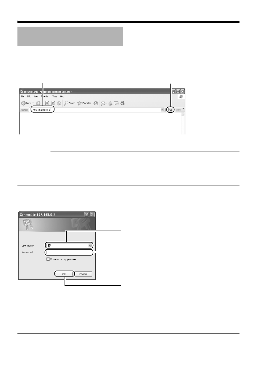
Einstellungen
IP-Adresseinstellungen
(fortsetzung)
䢇 Ändern der IP-Adresse mit dem Internet Explorer (fortsetzung)
4.Starten Sie den Internet Explorer
Geben Sie die folgende IP-Adresse in das Adressfeld ein.
A
http://192.168.0.2
Klicken Sie auf [Go].
B
Erinnerung:
● Wenn die Proxyservereinstellung im Internet Explorer aktiviert ist, können Sie die IP-Adresse unter
Umständen nicht direkt angeben. Ändern Sie in diesem Fall die Proxyeinstellungen im Internet
Explorer.
● Wenn das Dialogfeld Security Warning angezeigt wird, klicken Sie auf die Schaltfläche [OK], um
fortzufahren.
5.Geben Sie Benutzernamen und Passwort ein (die Anmeldung muss als Administrator
erfolgen)
A
Geben Sie den Benutzernamen ein.
VN-C215
Der Vorgabewert lautet CadminD.
B
Geben Sie das Passwort ein.
Der Vorgabewert lautet Cvn-c215D.
Klicken Sie auf [OK].
C
Erinnerung:
● Wenn das Dialogfeld Security Alarm angezeigt wird, klicken Sie auf die Schaltfläche [Yes], um
fortzufahren.
G-32
Page 78

6.Die Startseite der VN-C215V4U wird angezeigt
Klicken Sie auf [Network] und dann im
nächsten Untermenü auf [Basic].
7.Die Seite Basic mit den IP-Adresseinstellungen erscheint
A
B
DEUTSCH
Setzen Sie den Parameter [IP Setting]
auf [DHCP Disable].
Geben Sie die gewünschten Werte in
die Felder [IP Address], [Subnet Mask]
und [Default Gateway] ein.
Klicken Sie auf [OK].
C
Ein Bestätigungsfenster erscheint. Klicken Sie auf die Schaltfläche [OK]. Die VN-C215V4U wird unter
Verwendung der neuen IP-Adresse neu gestartet. Die Neuinitialisierung der Kamera dauert etwa eine
Minute.
Erinnerung:
● Der Zugriff von diesem Computer kann fehlschlagen, wenn die IP-Adresse der VN-C215V4U
geändert wurde. Um den Zugriff auf die VN-C215V4U vom selben Computer aus zu ermöglichen,
ändern Sie die IP-Adresse des Computers entsprechend.
G-33
Page 79

Einstellungen
IP-Adresseinstellungen
(fortsetzung)
Wenn die IP-Adresse der VN-C215V4U
bekannt ist
Wenn die IP-Adresse der VN-C215V4U bekannt
ist, kann sie mithilfe des Internet Explorer auf
dem Computer geändert werden, um die
integrierte Webseite der VN-C215V4U
aufzurufen.
T Weitere Informationen entnehmen Sie dem
Abschnitt CSetting Using Internet ExplorerD
im Dokument [EINLEITUNG], welches im
PDF-Format auf der beiliegenden CD-ROM
enthalten ist.
Wenn die IP-Adresse der VN-C215V4U
unbekannt ist
Eine Änderung der Einstellungen über einen
Computer ist nicht möglich, wenn die IP-Adresse
der VN-C215V4U unbekannt ist.
In diesem Fall müssen Sie die IP-Adresse
mithilfe der folgenden Methode ermitteln.
● Auf der beiliegenden CD-ROM befindet sich
ein Suchprogramm. Mithilfe dieses Tools
können Sie im LAN nach der VN-C215V4U
suchen.
Weitere Informationen zum Suchtool
entnehmen Sie dem Dokument CReadmeD
auf der beiliegenden CD-ROM.
G-34
Page 80

Betrieb
Betrieb des integrierten Viewers
Der integrierte Viewer gestattet die Anzeige
einer Folge von Bildern, die Einmalaufzeichnung
von Bildern und den Empfang von Alarmdaten.
⽧Einrichten des Internet Explorer (A S. 36)
⽧Installieren des integrierten Viewers
(A S. 38)
⽧Bildschirmkonfiguration des integrierten
Viewers (A S. 39)
⽧Beenden des integrierten Viewers (A S. 40)
⽧Verknüpfung zum integrierten Viewer
(A S. 41)
● Informationen zu den CBuilt-in Viewer
SettingsD entnehmen Sie dem Dokument
[EINLEITUNG], welches als PDFDokument auf der beiliegenden CD-ROM
zu finden ist.
DEUTSCH
G-35
Page 81

Betrieb
Betrieb des integrierten
Viewers (fortsetzung)
Einrichten des Internet Explorer
1.Starten Sie den Internet Explorer auf dem Computer
2.Wenn die Proxyeinstellung im Internet Explorer aktiviert ist, gehen Sie wie nachfolgend
beschrieben vor, um den Proxy für den Internet Explorer zu deaktivieren
● Wählen Sie [Tools]-[Internet Options...]-[Connections]-[LAN Setting]. Deaktivieren Sie dann das
Kontrollkästchen CUse a proxy server for your LAND im Bereich [Proxy Server] des Fensters
[Local Area Network(LAN)Settings].
Deaktivieren Sie das Kontrollkästchen
G-36
Page 82

3.Wenn Active X controls and plug-ins im Internet Explorer deaktiviert ist, gehen Sie wie folgt
vor, um es zu aktivieren
● Klicken Sie auf [Trusted sites] unter [Tools]-[Internet Options...]-[Security]. Daraufhin wird die
direkt unterhalb gelegene Schaltfläche [Sites...] verfügbar. Klicken Sie auf diese Schaltfläche
und deaktivieren Sie das Kontrollkästchen [Require server verification(https:) for all sites in this
zone] im angezeigten Fenster. Fügen Sie nun die IP-Adresse der VN-C215V4U hinzu. Wenn die
Werkseinstellungen nicht verändert wurden, fügen Sie die folgende Website zur Zone hinzu.
http://192.168.0.2
● Klicken Sie auf [Trusted sites] unter [Tools]-[Internet Options...]-[Security]. Klicken Sie auf die
Schaltfläche [Custom Level], um das Fenster [Security Settings] zu öffnen. Setzen Sie im
geöffneten Fenster alle Elemente in [Active X controls and plug-ins] auf [Enable].
DEUTSCH
4.Wenn die Popupblockerfunktion im Internet Explorer aktiviert ist, gehen Sie wie folgt vor, um
sie zu deaktivieren
T Der integrierte Viewer kann nicht verwendet werden, wenn für den Popupblocker die Einstellung
CEnableD gewählt ist.
● Die Auswahl von [Tools]-[Pop-up Blocker]-[Turn Off Pop-up Blocker] gestattet die Anzeige aller
Websites.
● Um nur bestimmte Sites wie die der VN-C215V4U zuzulassen, wählen Sie [Tools]-[Pop-up
Blocker]-[Turn On Pop-up Blocker] und danach die nun verfügbare Einstellung [Tools]-[Pop-up
Blocker]-[Pop-up Blocker Settings]. Das Fenster [Pop-up Blocker Settings] öffnet sich. Fügen Sie
in diesem Fenster die Adresse der VN-C215V4U als zulässige Websiteadresse hinzu.
5.Wenn Plug-In-Tools wie die Yahoo-Toolbar oder die Google-Toolbar im Internet Explorer
installiert sind, deaktivieren Sie die Popupblocker dieser Plug-Ins ebenfalls
G-37
Page 83

Betrieb
Betrieb des integrierten
Viewers (fortsetzung)
Installieren des integrierten Viewers
1.Geben Sie die URL des integrierten Viewers in das Adressfeld des Internet Explorer ein
Wenn etwa die IP-Adresse der VN-C215V4U 192.168.0.2 lautet, geben Sie Folgendes ein:
http://192.168.0.2/cgi-bin/c215viewing.cgi
Geben Sie die URL des integrierten Viewers dieser Kamera ein.
A
(Die Standard-URL lautet „http://192.168.0.2/cgi-bin/
c215viewing.cgi“.)
http://192.168.0.2/cgi-bin/c215viewing.cgi
2.Geben Sie den Benutzernamen und das Passwort ein
A
Geben Sie den Benutzernamen ein.
VN-C215
Der Vorgabewert lautet CadminD.
B
Geben Sie das Passwort ein.
Der Vorgabewert lautet Cvn-c215D.
C
Klicken Sie auf [OK].
Wählen Sie [Go]
B
3.Der Viewer wird installiert und gestartet
G-38
Page 84

Bildschirmkonfiguration des integrierten Viewers
● Standardmäßig kodiert die VN-C215V4U mit einer Rate von 15 fps.
DEUTSCH
A
B
C
D
E
A Alarm Blinkt, wenn Alarmpakete von der VN-C215V4U an den Computer gesendet
werden.
Die Schaltfläche blinkt fortlaufend, bis die automatische Alarmabschaltfunktion
ausgeführt wird. Ebenfalls abgeschaltet wird das Blinken durch Anklicken der
Schaltfläche.
B Display Size Schaltet die Anzeigegröße um( VGA oder QVGA).
C Pause Unterbricht die Wiedergabe von Bildern bzw. setzt sie fort.
D Capture Zeichnet das aktuell angezeigte Bild auf dem Computer auf.
Aufgezeichnete Bilder werden als JPEG-Dateien im Verzeichnis CC215_JPEGD
abgelegt, welches als Unterverzeichnis des Ordners [My Document] auf dem
Computer erstellt wird. Der Dateiname besteht aus Datum und Uhrzeit der
Aufnahme (Jahr/Monat/Tag, Stunde/Minute/Sekunde/Millisekunde).
Die im Dateinamen angegebene Uhrzeit basiert auf der Computerzeit und nicht
auf der internen Uhr der VN-C215V4U.
Diese Funktion kann keine bewegten Bilder aufzeichnen.
E Setup Ruft das Einstellungsfenster des integrierten Viewers auf.
Dieser Einstellungsbildschirm wird verwendet, um den integrierten Viewer als
Software auf dem Computer einzurichten.
Anmerkung:
● Die hier vorgenommenen Einstellungen werden nicht als Einstellungen der
VN-C215V4U übernommen.
T Weitere Informationen zu den Einstellungen finden Sie im Abschnitt
CBuilt-in Viewer SettingsD des Dokuments [EINLEITUNG]. Die
entsprechende Datei finden Sie im PDF-Format auf der beiliegenden
CD-ROM.
G-39
Page 85

Betrieb
Betrieb des integrierten
Viewers (fortsetzung)
Beenden des integrierten Viewers
Um den Viewer zu beenden, klicken Sie auf die Schließenschaltfläche oben rechts im Fenster.
Klicken Sie auf die Schließenschaltfläche.
● Um den integrierten Viewer neu zu starten, starten Sie den Internet Explorer und geben die URL
des integrierten Viewers in das Adressfeld ein.
Wenn etwa die IP-Adresse der VN-C215V4U 192.168.0.2 lautet, geben Sie Folgendes ein:
http://192.168.0.2/cgi-bin/c215viewing.cgi
● Wenn das Dialogfeld Security Warning angezeigt wird, klicken Sie auf die Schaltfläche [OK], um
fortzufahren.
G-40
Page 86

Verknüpfung zum integrierten Viewer
Das Erstellen einer Verknüpfung zum
integrierten Viewer auf dem Desktop des
Computers erspart Ihnen die Eingabe der URL
in den Internet Explorer.
Erstellen Sie die Verknüpfung wie nachfolgend
beschrieben.
1.Starten Sie den Internet Explorer
2.Klicken Sie mit der rechten Maustaste auf
dem Bildschirm auf Internet Explorer und
wählen Sie [Create Shortcut]
Klicken Sie im Bestätigungsdialogfeld auf
[OK]. Nun wird auf dem Desktop eine
Verknüpfung erstellt.
3.Klicken Sie mit der rechten Maustaste auf
das Verknüpfungssymbol auf dem Desktop
und wählen Sie „Eigenschaften“
Das Einstellungsfenster wird angezeigt.
4.Geben Sie die URL des integrierten
Viewers in das URL-Feld ein
Wenn etwa die IP-Adresse der VN-C215V4U
192.168.0.2 lautet, geben Sie Folgendes ein:
http://192.168.0.2/cgi-bin/c215viewing.cgi
5.Klicken Sie auf die Schaltfläche [OK], um
den Vorgang abzuschließen
Wenn Sie nun auf die Verknüpfung
doppelklicken, brauchen Sie die URL
nachfolgend nicht mehr in den Internet
Explorer einzugeben.
Erinnerung:
● Bevor Sie den integrierten Viewer über die
Verknüpfung starten, schließen Sie alle
Internet Explorer-Fenster. Wenn Sie den
integrierten Viewer über die Verknüpfung
starten, während noch andere Internet
Explorer-Fenster geöffnet sind, können
Fehlfunktionen beim Viewer auftreten.
DEUTSCH
G-41
Page 87

Sonstiges
Technische Daten
Kameraeinheit
Bilderfassungseinrichtung
Bildpunkte
(effektiv)
[Monitorausgang]
Monitorausgang × 1 (75, 1 Vp-p)
Horizontalauflösung
Erforderliche
Umgebungsbeleuchtung
(min.)
Videorauschabstand
[Netzwerkausgang]
Bildkomprimierungsformat
Bildgröße : 640 ⳯ 480 320 ⳯ 240
Netzwerkschnittstelle
LAN-Spezifikation
Kompatibilität mit IEEE802,3, IEEE802,3u und
IEEE802,3af
Kommunikationsprotokoll
: 1/4"-Interline-Transfer-CCD
: ca. 380.000 Bildpunkte
(768 (H) ⳯494 (V)
: 540 TV-Zeilen (typ.)
: 2,5 lx (typ. 50 %, F1,3,
Weitwinkelobjektiv, AGC
eingeschaltet)
0,75 lx (typ. 25 %, F1,3,
Weitwinkelobjektiv, AGC
eingeschaltet)
1,4 lx (typ. 50 %, F1,3,
Weitwinkelobjektiv,
Funktion „Easy Day and
Night“ eingeschaltet)
0,4 lx (typ. 25 %, F1,3,
Weitwinkelobjektiv,
Funktion „Easy Day and
Night“ eingeschaltet)
: 50 dB (typ. 50 %, AGC
abgeschaltet)
: JPEG
: RJ-45.100BASE-TX/
10BASE-T/FULL/HALF/
Unterstützung der
Autonegotiation
: TCP/IP, UDP, HTTP, FTP,
ICMP, ARP, RTP, DHCP,
SNTP, SMTP, IGMP
Allgemein
Alarmeingang :
Alarmausgang : NPN-Open-Collector-
Interner Speicher : 8 Mbyte
Versorgungsspannung
Leistungsaufnahme
Umgebungstemperatur
Relative
Umgebungsluftfeuchtigkeit
Gewicht : ca. 750 g
Spannungsfreier Kontakt,
NPN-Open-CollectorEingang, Nullpegel, Latch/
Momentausgabe (>500 ms).
(Arbeitsstrom bei
Niederpegel: 0,3 mA. Bei
Hochpegel angelegte
Spannung: 3,3 V).
Ausgang (Zulässige
Eingangsspannung: 12 V.
Zulässiger Eingangsstrom:
50 mA).
: 12 V DC oder -48 V DC
(Versorgung durch
Speisegerät, das Power
over Ethernet unterstützt)
: 0,5 A (max.)
:–10I bis 50 I (Betrieb)
0I bis 40 I (empfohlen)
: 35 % bis 85 %
(Kondenswasserbildung
vermeiden)
Lieferumfang/Zubehör
Einstiegshandbuch .......................................... 1
CD-ROM.......................................................... 1
Garantiekarte................................................... 1
Servicekarte..................................................... 1
Schablone........................................................ 1
G-42
Page 88

Abmessungen [Einheit: mm (Zoll)]
71 (2-13/16)
58 (2-5/16)
55 (2-3/16)
Ǿ116 (4-9/16)
133 (5-1/4)
Ǿ120 (4-3/4)
83,5 (3-5/16)
46 (1-13/16)
89 (3-1/2)
6 (1/4)
4,5 (3/16)
Ǿ145 (5-3/4)
Ǿ145 (5-3/4)
89 (3-1/2)
SR55 (2-1/8)
4-Ǿ4,5 (3/16)
SR55 (2-1/8)
⽧Bei montierter Abdeckung
⽧Bei versenktem Einbau
DEUTSCH
T Technische Daten und das Erscheinungsbild des Geräts und zugehöriger Produkte können im
Sinne einer stetigen Produktverbesserung ohne vorherige Ankündigung geändert werden.
G-43
Page 89

FIXED IP DOME CAMERA
VN-C215V4U
FRANÇAIS
MANUEL DE
DÉMARRAGE
Merci d'avoir acheté ce produit JVC.
Avant de commencer à l'utiliser, veuillez lire
les instructions attentivement pour garantir
les meilleures performances possibles.
Page 90

Introduction
Consignes de sécurité
ATTENTION
Pour éviter les chocs électriques, ne pas
ouvrir le coffret. Aucune pièce à l’intérieur
n’est à régler par l’utilisateur. Confier les
opérations d’entretien au personnel de
service qualifié.
Cher client,
Cet appareil est conforme aux directives et
normes européennes en vigueur relatives à
la compatibilité électromagnétique et à la
protection électrique.
Représentant européen de Victor Company
of Japan Limited:
JVC Technology Centre Europe GmbH
P.O. Box 10 05 52
61145 Friedberg
Allemagne
Informations relatives à l élimination des appareils usagés,à
l'fintention des utilisateurs
[Union européenne]
Lorsque ce symbole figure sur un appareil électrique et électronique, cela
signifie qu'il ne doit pas être éliminé en tant que déchet ménager à la fin de
son cycle de vie. Le produit doit être porté au point de pré-collecte approprié
au recyclage des appareils électriques et électroniques pour y subir un
Attention :
Ce symbole
n’estque dans
reconnu l’Union
européenne.
traitement, une récupération et un recyclage, conformément à la législation
nationale.
En éliminant correctement ce produit, vous contriburez à la conservation des
ressources naturelles et à la prévention des éventuels effets négatifs sur
l'environnement et la santé humaine, pouvant être dus à la manipulation
inappropriée des déchets de ce produit. Pour plus d'informations sur le point
de pré-collecte et le recyclage de ce produit, contactez votre mairie, le
service d’évacuation des ordures ménagères ou le magasin dans lequel
vous avez acheté le produit.
Des amendes peuvent être infligées en cas d’élimination incorrecte de ce
produit, conformément à la législation nationale.
(Utilisateurs professionnels)
Si vous souhaitez éliminer ce produit, visitez notre page Web
www.jvc-europe.com
[Pays ne faisant pas partie de l'Union européenne]
Si vous souhaitez éliminer ce produit, faites-le conformément à la législation
nationale ou autres règles en vigueur dans votre pays pour le traitement des
appareils électriques et électroniques usagés.
afin d'obtenir des informations sur sa récupération.
F-2
Page 91

● L’installation doit être effectuée par une
personne qualifiée, en conformité avec
toutes les réglementations locales.
● Cette installation doit être conforme au
National Electrical Code, ANSI/NFPA 70.
● Ce produit doit être connecté à une
alimentation électrique CC 12 volts.
● L’alimentation électrique CC 12 volts doit
satisfaire aux spécifications suivantes:
Classe 2 uniquement (États-Unis),
alimentation électrique isolée (Europe et
autres).
● Toute mention dans ce manuel d’entrées/de
sorties d’alarme n’a pas été évaluée par UL
pour une utilisation comme alarme antivol.
● Il est possible que l’encastrement de
caméras dans le plafond ne soit pas autorisé
par les réglementations dans certaines
régions. Veuillez consulter le détaillant JVC
agréé le plus proche pour obtenir de plus
amples détails.
● Le plafond sur lequel la caméra sera montée
doit être suffisamment solide pour supporter
le poids de ce produit. Si votre plafond n’est
pas suffisamment solide, vous devez le
renforcer avant toute installation.
● L’étiquette d’évaluation est placée sur le côté
de la caméra.
● La caméra peut tomber si les vis et les
écrous de montage ne sont pas correctement
serrés. Vérifier que les vis et les écrous sont
correctement serrés.
● Nous rejetons toute responsabilité en cas
d’endommagement de la caméra suite à une
chute due à une installation incomplète ou au
non-respect des instructions d’installation.
Installer la caméra avec soin.
● Ne pas installer la caméra à proximité de
lampes d’éclairage à température élevée,
comme un projecteur. Cela pourrait causer
un mauvais fonctionnement ou un incendie.
Ce manuel décrit l’utilisation élémentaire
de VN-C215V4U.
Pour les instructions d’utilisation
détaillées de VN-C215V4U, consulter
AINSTRUCTIONSB.
Consulter le fichier AReadmeB sur le CDROM pour les dernières informations.
● Le CD-ROM inclus [INSTRUCTIONS]
(pdf), [API Guide] (pdf) et [Search Tool].
● Pour afficher le fichier en format pdf,
AAdobe ReaderB doit être installé sur
l’ordinateur.
FRANÇAIS
● Avant de commencer un enregistrement
important, toujours effectuer un
enregistrement test pour vérifier que tout
fonctionne normalement.
● Nous ne fournirons absolument aucune
indemnisation pour le contenu devant être
enregistré ou pour les opportunités ratées
dans les cas o’u l’enregistrement n’est pas
effectué correctement en raison d’un
mauvais fonctionnement de la caméra
vidéo, du magnétoscope, de l’enregistreur
sur disque dur ou de la bande vidéo.
● Avant de régler l’angle de prise de vue,
toucher la surface métallique de la borne
[MONITOR] afin de libérer l’électricité
statique de votre corps.
F-3
Page 92

Introduction
Fonctions principales
䡵 Qualité supérieure de l’image
La caméra de VN-C215V4U emploie un CCD de
380.000 pixels (1/4") qui permet une qualité
d’image supérieure.
䡵 Portée de prise de vue large
La portée de réglage de l’angle de prise de vue
est large et la caméra peut être installée sur un
mur à l’aide d’un mécanisme de réglage de la
rotation.
䡵 Conception sans blocage
La conception en forme de dôme permet une
grande facilité d’utilisation, sans blocage de la
caméra.
䡵 Encastrement dans le plafond sans
utilisation de supports
La caméra peut être encastrée dans le plafond
sans utiliser de supports encastrés.
䡵 Objectif varifocal très puissant
L’objectif varifocal intégré (zoom optique 3,6x)
permet une surveillance rapprochée.
䡵 Surveillance de nuit
VN-C215V4U dispose d’une fonction de
luminance faible (fonction Jour et nuit
conviviale), qui passe automatiquement en
mode de sensibilité élevée (noir et blanc) en cas
de luminosité faible.
䡵 Prise en charge de PoE (Power over
Ethernet - Alimentation par Ethernet)
VN-C215V4U prend en charge PoE
(IEEE802.3af) et permet l’alimentation électrique
à partir d’un câble réseau local.
䡵 Réalisation de la fréquence d’images
totale
La transmission des données est possible au
format VGA à un débit de 30 tps.
䡵 Serveur Web intégré
Le réglage est possible en utilisant Internet
Explorer.
䡵 Prise en charge de la multidiffusion
VN-C215V4U prend en charge la multidiffusion,
ce qui permet la transmission des données
d’images à plusieurs ordinateurs sur le réseau
sans réduire le débit de trames.
䡵 Fonction de détection de mouvement
Cette fonction active une alarme en cas de
détection de mouvement dans l’image à
l’intérieur d’une zone prédéfinie.
Les fichiers d’images pré-enregistrés/postenregistrés peuvent être envoyés par FTP à
l’aide de l’entrée d’alarme.
䡵 Visionneuse intégrée
Il est possible d’effectuer la surveillance sur un
ordinateur en téléchargeant la visionneuse
intégrée sur l’ordinateur.
䡵 API HTTP
VN-C215V4U dispose d’une API fondée sur
HTTP. Cette fonction permet le réglage et le
contrôle par le biais du réseau.
Comment afficher ce manuel
䡵 Symboles utilisés
Remarque: Décrit les éléments portant sur le
fonctionnement de ce produit.
Mémo : Décrit l’information de référence,
notamment les fonctions et les
restrictions d’utilisation de ce
produit.
A : Indique les numéros des pages
de référence et les éléments de
référence.
䡵 À propos du contenu de ce manuel
● Tous droits réservés par JVC. Toute
reproduction ou réimpression non
autorisée de ce manuel, en partie ou en
intégralité, est strictement interdite.
● Windows est une marque déposée de
Microsoft Corporation aux États-Unis.
● Tous les autres noms de produits utilisés
dans ce manuel sont des marques
commerciales ou des marques déposées
appartenant à leurs entreprises
respectives. Remarque: Les marques
telles que 姠, 姞 et 姝 ont été omises dans ce
manuel.
● Les designs illustrés, les spécifications et
tout autre contenu de ce manuel peuvent
être modifiés à tout moment à des fins
d’amélioration sans aucun préavis.
F-4
Page 93

Contenu
Introduction
Consignes de sécurité ........................ 2
Fonctions principales .......................... 4
Contenu .............................................. 5
Environnement opérationnel ............... 6
Consignes de sécurité ........................ 6
Nom et fonction des pièces ................ 8
Caractéristiques ................................ 12
Configuration
Procédures générales ...................... 14
Montage de la caméra ...................... 14
Préliminaires ................................. 14
Choix de la méthode de montage
Montage au plafond ...................... 15
Montage de la caméra directement
au plafond ou au mur ............. 18
Installer de manière à ce que le
câble sorte par le côté ............ 20
Montage de la caméra sur le coffret
électrique ................................ 20
Alimentation électrique ..................... 22
L’utilisation du PoE ........................ 22
Connexion à une alimentation
électrique DC 12 volts ............ 23
Connexion du câble de réseau local 24
Connexion du câble de l’entrée et de
sortie d’alarme ........................... 24
Réglage des images ......................... 25
Installation du dôme protecteur ........ 27
.... 15
Réglages
Spécifications de réseau ...................28
Paramètres de l’adresse IP ............... 29
T Pour ASetting Using Internet
ExplorerB, vous reporter aux
[INSTRUCTIONS] (pdf) fournies sur
le CD-ROM.
Fonctionnement
Fonctionnement de la visionneuse
intégrée ...................................... 35
Configuration de Internet Explorer
Installation de la visionneuse
intégrée ...................................38
Configuration de l’écran de la
visionneuse intégrée ...............39
Quitter la visionneuse intégrée ......40
Raccourci pour la visionneuse
intégrée ...................................41
Autres
Spécifications ....................................42
..... 36
FRANÇAIS
F-5
Page 94

Introduction
Environnement opérationnel
䡵 Configuration de l’ordinateur
Système
d’exploitation
CPU : Pentium 4 1,5 GHz (ou
Mémoire : 1 Go et plus
Espace du
disque dur
Carte vidéo : 1024 ⳯ 768 pixels ou plus,
Navigateur Web : Internet Explorer Version 6.0
䡵 Réseau local
● 10BASE-T/100BASE-TX réseau
interconnecté utilisant un concentrateur de
commutation conforme à la norme
IEEE802,3.
● Un concentrateur de commutation conforme
à la norme IEEE802,3af lorsqu’un PoE est
utilisé.
● Un réseau conforme à la norme IGMPv2
lorsqu’une multi-diffusion est utilisée.
Mémo:
● Les caractéristiques informatiques ci-dessus
sont fournies uniquement à titre de guide afin
d’obtenir une utilisation uniforme des
applications, elles ne peuvent en aucun cas
garantir leur fonctionnement.
● En tenant compte des conditions d’utilisation,
les applications peuvent fonctionner
irrégulièrement même si l’ordinateur de
l’utilisateur est doté de toutes les
spécifications requises.
: Windows XP (Professional ou
Home Edition) (SP2)
supérieur)
: 20 Mo d’espace libre ou plus
True Color (24 ou 32 bits)
Consignes de sécurité
Maintenance et environnement
opérationnel
䢇 Cette caméra est conçue pour être utilisée à
l’intérieur. Elle ne convient pas à une
utilisation à l’extérieur.
䢇 Ne pas ranger dans les endroits suivants,
au risque d’entraîner un mauvais
fonctionnement ou une défaillance.
● Endroits chauds ou froids excédant une
plage de température se situant entre 10I et 50I.
Endroits excédant une plage d’humidité
●
entre 35 % RH et 85 % RH acceptable pour
un bon fonctionnement. (la condensation
peut nuire à son fonctionnement)
● Près d’un équipement qui émet des
champs magnétiques puissants, tel un
transformateur ou un moteur.
● Près d’un équipement qui émet des ondes
radios, tel un transmetteur radio ou des
téléphones portables.
Endroits exposés à la poussière ou au sable.
●
●
Endroits exposés à des vibrations excessives.
● Endroits exposés à l’humidité, à côté
d’une fenêtre, par exemple.
● Endroits soumis à la vapeur ou à l’huile,
une cuisine, par exemple.
● Endroits émettant des radiations, rayons
X ou des gaz corrosifs.
L’utilisation de cette caméra et de ses câbles de
䢇
connexion dans des lieux soumis à l’émission
d’ondes électromagnétiques puissantes (p. ex.
près d’une radio, télévision, transformateur,
moniteur, etc.) peut entraîner l’apparition
d’images brouillées ou modifier les couleurs.
䢇 Ne pas installer dans un endroit soumis à
une circulation d’air froid, tel qu’à proximité
de la sortie d’air d’un climatiseur. Le dôme
peut se brouiller sous l’effet d’un changement
brusque de la température.
䢇 Ne pas installer dans un endroit où la chaleur
peut s’accumuler.
Cet appareil produit également de la chaleur
émise par la surface de l’unité principale. Par
conséquent, ne pas installer dans un endroit
où la chaleur peut être emprisonnée, tel un
angle de murs.
F-6
Manipulation de l’appareil
䢇 Ne pas boucher les ouvertures d’aération de
l’appareil.
Une mauvaise ventilation de la chaleur peut
entraîner un mauvais fonctionnement de
l’appareil. S’assurer de ne pas bloquer les
ouvertures d’aération.
Page 95

Autres
䢇 Cette caméra est dotée d’un circuit intégré
AGC. Lorsque AGC est AOnB (allumée), la
sensibilité de la caméra augmente
automatiquement dans les lieux sombres et
l’image à l’écran peut paraître granuleuse. Il
ne s’agit pas d’une défectuosité de l’appareil.
Lorsque White Balance est réglée sur AAutoB, le
䢇
principe de fonctionnement du circuit d’équilibrage
des blancs à réglage automatique peut faire
différer la couleur de l’image lorsqu’elle est
comparée à la couleur réelle de l’objet, en fonction
de l’état de l’objet. Cependant, il ne s’agit pas
d’une défectuosité de l’appareil.
䢇
Si la caméra enregistre un objet très lumineux
(une lampe, par exemple), des lignes verticales
peuvent apparaître sur l’image (bavures) ou
l’image peut devenir floue autour de l’objet
lumineux (halo). Il s’agit d’une caractéristique
du CCD et non d’une défectuosité.
䢇
L’obturateur électronique de cette caméra est
réglé, par défaut, à 1/60e. Afin d’éviter le
clignotement sous un éclairage fluorescent (à
moins d’un inverseur illumination) placé dans
un endroit ayant une fréquence électrique
commerciale de 50 Hz, commuter la vitesse du
volet à 1/100e. (La sensibilité augmente un peu
lorsque la vitesse du volet est réglée à 1/100e.)
䢇
Si la fonction Easy Day and Night est activée
AOnB
), l’image passe au noir et blanc dans
(
les endroits obscurs. A mesure que la
sensibilité augmente, les images peuvent
paraître granuleuses et présenter des points
blancs. En outre, lorsque les images en
couleur passent au mode noir et blanc, les
zones plus claires de l’image sont accentuées
et semblent difficiles à voir. Cependant, il ne
s’agit pas d’une défectuosité de l’appareil.
䢇
L’image peut être déformée ou contenir des bruits
lorsque la tension est coupée instantanément ou
fluctue suite à un foudroiement ou encore lors de
l’activation d’un climatiseur.
䢇
La caméra est réglée sur un grand angle de
rotation afin d’offrir une grande portée de
surveillance. Si le zoom de l’objectif est grand
et que l’angle d’inclinaison est réglé à environ
⬚
, l’angle de rotation peut causer la
±80
réflection du dôme protecteur dans l’image. Le
cas échéant, régler l’angle du champ. (
䢇
Utiliser le commutateur de réseau conforme à
la norme IGMPv2, en cas de multi-diffusion.
䢇
La caméra peut être alimentée en courant soit
en utilisant le PoE ou en la branchant avec la
prise de courant DC 12 volts. N’utiliser qu’un
seul moyen d’alimentation de courant. Le fait
de brancher le câble d’alimentation et le câble
de réseau du PoE en même temps peut
entraîner une défaillance ou un défectuosité
de la caméra. (
A
p. 22, 23)
A
p. 27)
Droits d’auteur de la vidéo
䢇 A moins que l’utilisateur soit le détenteur des
droits d’auteurs ou lorsque la reproduction
bénéficie d’une autorisation, etc. par le
détenteur des droits d’auteurs, par principe
une autorisation est requise pour effectuer
une reproduction, modification, transmission,
etc. de la vidéo-audio soumises aux droits
d’auteur.
Une reproduction, modification, transmission,
etc. non autorisée du matériel soumis aux
droits d’auteur peut constituer une violation
des droits d’auteur et l’utilisateur peut être
obligé de verser une compensation pour tout
dommage encouru. Lors de l’utilisation d’une
vidéo/audio soumise aux droits d’auteur,
vérifier attentivement l’entente de licence, ou
autre, du matériel soumis aux droits d’auteur.
Lorsqu’il y a des droits ou des droits de
détenteur du sujet reproduit, une autorisation
peut être requise pour filmer ou l’utiliser
(traitement). Vérifier attentivement les
conditions de licence.
Maintenance
䢇 S’assurer de mettre le circuit électrique hors
tension avant d’effectuer la maintenance.
䢇 Essuyer avec un chiffon doux.
L’utilisation d’un diluant ou de benzène peut
dissoudre ou ternir la surface. Pour enlever la
saleté tenace, essuyer avec un chiffon
imbibé d’un détergent doux dilué dans l’eau,
puis essuyer avec un chiffon sec.
Économie d’énergie
䢇 Lorsque l’appareil n’est pas utilisé pendant
un certain temps, couper le courant au
système afin d’éviter tout risque et réduire la
consommation d’électricité.
FRANÇAIS
F-7
Page 96

Introduction
Nom et fonction des pièces
Caméra
I
A
B
C
D
E
Trou de montage (elliptique) ⳯ 4
A
Pour le montage de la caméra sur le coffret
électrique.
(A p. 20)
B Trou de montage (rond) ⳯ 4
Pour le montage de la caméra au plafond ou au
mur. (A p. 18, 20)
C Boîtier extérieur
Le boîtier doit être utilisé dans les conditions
suivantes:
● Montage direct de la caméra au plafond ou
au mur. (A p. 18)
● Montage de la caméra sur le coffret
électrique. (A p. 20)
D Dôme protecteur
Le dôme protecteur est fragile. Le manipuler
avec précaution.
E Dôme intérieur
Déposer le dôme intérieur avant d’installer la
caméra et effectuer un réglage d’angle de
l’image. (A p. 16, 18)
H
B
A
G
F
Status
Link
Act
F Témoin de fonctionnement
[Status] Témoin d’état
Le témoin clignote lorsque le courant est activé
et il est éteint lorsque le démarrage de la caméra
est terminé. Vérifier la caméra ou l’appareil
branché si le témoin continue à clignoter alors
que la caméra est en fonction.
[Link] Témoin de liaison
Ce témoin s’allume lorsque la caméra est reliée
ou connectée au réseau.
[Act] Témoin d’activité
Ce témoin s’allume pendant une activité, par
exemple la transmission ou la réception de
données.
G Trou de câblage
Ce trou sert à passer les câbles depuis le côté
de la caméra sans avoir à percer un trou dans le
plafond.
(A p. 20)
F-8
Page 97

Caméra/Intérieur de la caméra
T Cette illustration représente l’intérieur de la caméra, lorsque le dôme protecteur, le boîtier intérieur
et extérieur sont enlevés.
Procédure de retrait ( A p. 15 AMontage au plafondB étapes 3. à 5.)
Objectif
(A p. 11)
W
J
K
L
M
N
H Alimentation/câble de l’alarme
(A p. 22, 24)
Nom du signal Couleur du câble
Entrée d’alarme 1 Rose
Entrée d’alarme 2 Bleu
Sortie d’alarme 1 Orange
Sortie d’alarme 2 Jaune
Mise à terre Brun
Alimentation électrique + DC
Alimentation électrique - DC
12 volts
12 volts
Remarque:
● Ne pas utiliser le PoE ensemble avec une
alimentation de courant DC 12 volts. Un
branchement simultané pourrait entraîner
une défaillance ou une défectuosité.
I
[10BASE-T/100BASE-TX(PoE)] Connecteur
pour connexion de câble réseau local (RJ-45)
(A p. 24)
J Courroie
Cette languette connecte la caméra au dôme
protecteur.
Rouge
Noir
Arrière de la caméra
V
U
T
P
Y
MAC address
S
R
X
Q
P
O
K Vis de fixation (3)
Il s’agit de la vis principale du support de
montage au plafond Q, qui sert à encastrer la
caméra dans le plafond.
L [RESET] Bouton de remise à zéro
Ce bouton permet de réinitialiser la caméra. Appuyer
sur ce bouton pendant 5 secondes puis relâcher afin
de réinitialiser la caméra. Environ une (1) minute est
nécessaire pour réinitialiser la caméra. Lors du
démarrage, le bouton [RESET] est désactivé.
Remarque:
● La caméra passe au mode de vérification de
service lorsque le bouton [RESET] est
enfoncé pendant cinq (5) secondes ou plus.
Ne pas enfoncer le bouton pendant cinq (5)
secondes ou plus.
M [MONITOR] Borne moniteur (broche RCA)
(A p. 25)
N Caméra
O Crochet de fixation antichute
P Attache métallique antichute (fournie) et
vis de montage métallique
Fixer la caméra N et le boîtier extérieur C au
moyen du crochet de fixation de l’attache
métallique antichute
O
.
FRANÇAIS
F-9
Page 98

Introduction
Nom et fonction des pièces
(Suite)
Intérieur de la caméra
Objectif
(A p. 11)
W
J
K
L
M
N
Support de montage au plafond (3)
Q
Ces supports doivent être utilisés pour encastrer
la caméra dans le plafond. (A p. 15)
R Vis de fixation de la caméra
Cette vis permet de fixer la caméra N et le
boîtier extérieur C. Pour effectuer la dépose
(A p. 16, 18)
S Vis de fixation panoramique
Desserrer cette vis avant de procéder au
réglage. Serrer uniquement la vis lorsque l’on
utilise la caméra dans des endroits soumis à de
fortes vibrations afin que l’angle de vue ne se
dérègle pas. (A p. 26)
T Repère de l’angle d’image
Installer la caméra en alignant l’angle d’image
avec la flèche repère.
U Bouton de rotation
Ce bouton sert à faire tourner l’objectif pour
ajuster l’angle d’inclinaison de l’image. (A p. 26)
V Repère du centre de rotation
(A p. 26)
Arrière de la caméra
V
U
T
P
Y
MAC address
S
R
X
Q
P
O
W Vis de blocage d’inclinaison
Après avoir ajusté l’angle de vue, serrer la vis
afin que l’angle de vue de la caméra ne puisse
être désaligné lorsque la caméra est posée dans
des endroits soumis à de fortes vibrations.
(A p. 26)
X Trou de montage et vis métallique
antichute
La vis sert à fixer le câble antichute au plafond.
(Le câble antichute n’est pas fourni.)
Y [MAC address] Témoin de l’adresse MAC
L’adresse MAC est l’adresse physique unique à
l’appareil. Cette adresse ne peut être modifiée.
F-10
Page 99

Objectif
SPOT
Z
a
Z
[FOCUS ADJ] Bouton d’ajustement de
FOCUS ADJ
IRIS ADJ
FOR SERVICE
L
IRIS
LEVEL
H
l’objectif
Ce bouton sert à ajuster l’objectif.
Enfoncer ce bouton pour ouvrir l’iris de l’objectif
pendant 30 secondes. L’objectif devient plus
facile à régler car la profondeur du champ est
plus profonde. (A p. 27)
Mémo:
● L’obturateur électronique est
automatiquement activé par l’enfoncement
du bouton de réglage de la mise au point.
L’image à l’écran peut papilloter, ceci n’est
toutefois pas une défectuosité.
a [IRIS LEVEL] Cadran d’ajustement de l’iris
Le cadran permet de régler le degré d’iris de
l’obturateur automatique.
Habituellement, le réglage n’est pas nécessaire.
Régler au besoin, en fonction des conditions
d’utilisation de l’appareil.
Pour obscurcir :
Pour éclaircir : Dans le sens horaire (vers H)
Dans le sens antihoraire (vers L)
b
c
FRANÇAIS
Mémo:
● Régler le degré d’iris après que [AGC] est
réglé à AOffB. Pour AAGC les réglages de la
fonction B, se reporter aux [INSTRUCTIONS]
(PDF) fournis avec le CD-ROM.
● Si AOffB n’est pas réglé, le fait de tourner le
cadran sur L activera la fonction AGC. La
sensibilité de la caméra augmentera et
l’image deviendra granuleuse.
b Bague d’ajustement de l’objectif
Déplacer la bague horizontalement pour régler
de l’objectif.
(A p. 27)
c Bague d’ajustement du zoom
Déplacer la bague horizontalement pour régler
l’angle de champ. (A p. 27)
F-11
Page 100

Introduction
Caractéristiques
Surveillance avec visionneuse intégrée
La VN-C215V4U est livrée avec une
visionneuse ActiveX intégrée.
Il est possible de visualiser les images de la VNC215V4U sur ordinateur en effectuant
l’installation de la visionneuse intégrée sur ce
dernier. Les images en cours de visionnement
peuvent également être conservées sur le
disque dur de l’ordinateur.
AFonctionnement de la visionneuse intégréeB
(A p. 35)
VN-C215V4U
Réseau
Ordinateur
Surveillance par multidiffusion
L’utilisation de plusieurs ordinateurs pour
effectuer la surveillance est possible grâce à la
multidiffusion.
Sauvegarde des images JPEG sur le
serveur FTP à intervalles réguliers
Les images JPEG peuvent être téléchargées sur
le serveur FTP à intervalles réguliers.
VN-C215V4U
Envoi régulier au
FTP des plus
récentes images
Réseau
Ordinateur
Alarme
Le VN-C215V4U est dotée de la fonction de
détection de mouvement et d’une alarme
double.
La détection de mouvement ou l’alarme peuvent
déclencher des activités telles que livraison de
courrier, transmission de message par TCP/
UDP, alarme.
Il est possible de déclencher une combinaison
d’entrées d’alarme.
L’installation d’un serveur FTP permet de
télécharger des images avant et après l’heure
d’entrée de l’alarme (pré et post-enregistrement)
au serveur.
VN-C215V4U
F-12
Réseau
conforme à la
norme IGMPv2
Ordinateur
Ordinateur
Ordinateur
VN-C215V4U
Envoi d’images
avant et après
l’entrée d’alarme
Dispositif
d’alarme
Réseau
Ordinateur
 Loading...