

Page 1
1.1
V
1.1
I
Instruction
Book
COLOR
VM-R190SU
' .
VIDEO
~0~~
MONITOR
.
~·
For Customer Use:
Enter
below
on
this
No.
the
the rear
information
VM-R190SU
located
Retain
reference.
Model
Serial
of
No.
the
for
whii:h
cabinet.
furture
is
Page 2

Thank you
and incorporates many useful
To
ensure a
this
booklet
•
Multi-standard
fessional
ponent video and
addition
• 19-lnch medium-high-resolution CRT,
comb
more than
•
Multi-function
facilities
lamp,
• Mountable
mount
tion
for
purchasing a
JVC
color
functions.
complete
and keep
compatibility
applicantions; accepting composite video,
to
external
filter
for
600
lines.
and superior
required
remote
manual
control
in a standard
adapter RK-19U.
of
the
understanding
it
in a
both
RGB
sync input.
pictures
with
by
professional
connector, etc.
(For
RK-19U.)
safe
place
for
a wide range
analog
a
horizontal resolution
flexibility
users
EIA
rack
mounting,
video
of
for
and
TTL
together
with
including
with
refer
the
monitor
future
signals
numerous
optional
to
the
monitor.
and
reference.
of
pro-
com-
in
with
a
of
a
tally
rack
instruc-
Your
new
monitor
to
extend
Safety
Controls
(Front
(Rear
Connections . . . . . . . . . . . . . . . . . . . . . . . . . . . . . . 8
Connections
Specifications
its
Precautions
and Connectors
Panel)
Panel)
Outline
will
provide superior
service
...........................
...........................
..........................
life,
please
.........................
Diagram . . . . . . . . . . . . . . . . . . . 9
read
quality
all instructions in
picture
·.
. . 1
.
2
.
4
.
6
0
<::AUTION:
REFER
SERVICING
TO
REDUCE
THE
RISK OF
DO
NOT
REMOVE
NO
USER-SERVICEABLE
TO
The
lightning flash
within
an
alert
the
"dangerous voltage"
enclosure
tude
to
persons.
The
triangle
presence
tenance (servicing) instructions in
ture
constitute a risk
exclamation
accompanying the
COVER
QUALIFIED
equilateral triangle
user·
to
the presence
that
may
is
of
point
intended
important
ELECTRIC
(OR
PARTS
BACK).
INSIDE.
SERVICE
with
PERSONNEL.
arrowhead
of
within
be
of
sufficient
of
electric
within
to
alert the user
operating
appliance. ·
is
the product's
an
SHOCK.
symbol,
intended
uninsulated
equilateral
and
the
magni-
shock
to
main-
litera-
to
to
the
In
order
to
prevent any
or
mishandling
ing precautions.
of
the
WARNINGS
To
prevent
monitor
Dangerous high voltages
not
remove
When servicing
personnel.
to
Never
fire
rain
or
the
back cover
the
try
fatal
accidents caused
monitor,
or
shock hazard,
moisture.
are
monitor,
to
service
be
fully
aware
do
not
present inside the
of
the cabinet.
contact
it
qualified
yourself.
by
misoperation
of
all
the
expose this
unit.
service
follow-
Do
Page 3
CAUTION
For connection
ferrite-core shielded cable
Ask
you
local
to
a computer
dealer about obtaining this
via
(JVC
the
Part No.
INFORMATION
This
equipment
energy and if
in
strict
accordance with
tions,
may
reception.
ply
with
the
accordance
Part 15
of
resonable
residential
guarantee
ticular installation.
terference
be determined by turning
the
user
is
ference
by
Reorient
Relocate
Move
the
Plug
the
computer
circuits.
If
necessary,
experienced radio/television technician
suggestions.
prepared by
sion helpful:
"How
to
Identify and Resolve Radio-TV
Problems"
This
booklet
Printing Office, Washington,
004-000-00345-4.
This
monitor
plug
to
satisfy
plug
into
the
generates and uses radio frequency
not
installed
and used properly,
the
cause interference
It has been
limits
with
type
for
a
the
specifications
to
tested and
Class
FCC Rules, which are designed
protection
installation.
that
to
radio
against such interference in a
However, there
interference
If
or
will
this
equipment
television reception, which can
the
encouraged
one
or
the
receiving antenna.
the
computer
computer
computer
to
try
more
of
the
with respect
away from
into a different
and receiver are on different branch
the
user should
The
user may find
the
Federal Communications Commis-
is
available from
consult
D.C.,
is
equipped with a 3-blade grounding-type
FCC
rule.
If
you are unable
outlet,
contact
your electrician.
TTL
connector,
CH20212-00JPG).
cable.
use
that
manufacturer's instruc-
radio and television
found
to
com-
8 computing device
in
not
occur
does cause
equipment
to
correct
following
to
the
receiver.
outlet
the
for
the
following
Subpart
the
dealer
to
provide
is
in
a par-
off and
the
inter-
measures:
receiver.
so
or
additional
booklet
J
no
in-
on,
that
an
Interference
the
US
Government
20402,
Stock
to
insert
No.
the
is,
in
of
the
PRECAUTIONS
•
Use
only
the
power source specified on
located on rear of
•
When
not
using this
cleaning
AC
•
Do
not
•
Do
result
•
Avoid using this
it,
outlet.
not
allow anything
locate this
not
overload wall
in
a fire or electric shock.
in
extremely hot,
in
dusty
near appliances generating strong magnetic
in
places subject
in
badly ventilated places.
•
Do
not
cover
could
obstruct
•
When
dust
soft
cloth.
•
Unplug this
qualified service personnel under
- When
the
If liquid has been
If
the
unit
erating instructions.
If
the
unit
damaged.
- When
the
ance.
•
Do
not
attempt
removing covers may expose you
other
hazards. Always refer servicing
personnel.
•
When replacement parts are required, have
sonnel verify in writing
have
the
same safety characteristics
Use
of manufacturer's specified replacement parts can pre-
vent
fire, shock, or
•
Upon
completion
please ask
described
•
When this
disposal
the
in
unit
could
qualified service personnel
the
cabinet.
unit
for a long period
be sure
to
unit
where people
disconnect
to
rest on
the
the
will
outlets or power
unit
under
the
following
cold or humid
places,
places,
to
direct sun
the
ventilation slots while
the
required ventilation.
accumulates on
unit
from
the
I ight,
the
screen surface, clean with a
AC
outlet
the
power cord
does
is
frayed
spilled
into
not
operate normally
or
the
has been dropped or
unit
exhibits a distinct change
to
service this
unit
to
that
the
replacement parts he uses
other
hazards.
of
any servicing
service personnel
the
manufacturer's service literature.
reaches
the
end
to
perform
of
its useful
result in a picture
to
dispose of this
the
rating label
of
time,
or when
power plug from
power
cord.
And
tread on
cords
the
cord.
as this can
conditions:
fields,
and
in
operation
as
and refer servicing
following conditions:
plug
is
damaged.
unit.
following
the
cabinet
the
has been
in
perform-
yourself as opening
dangerous voltage or
to
qualified service
the
service per-
as
the
original parts.
or
repair
to
this
unit,
the
safety
check
life,
improper
tube
implosion. Ask
unit.
the
do
this
to
op-
or
Page 4
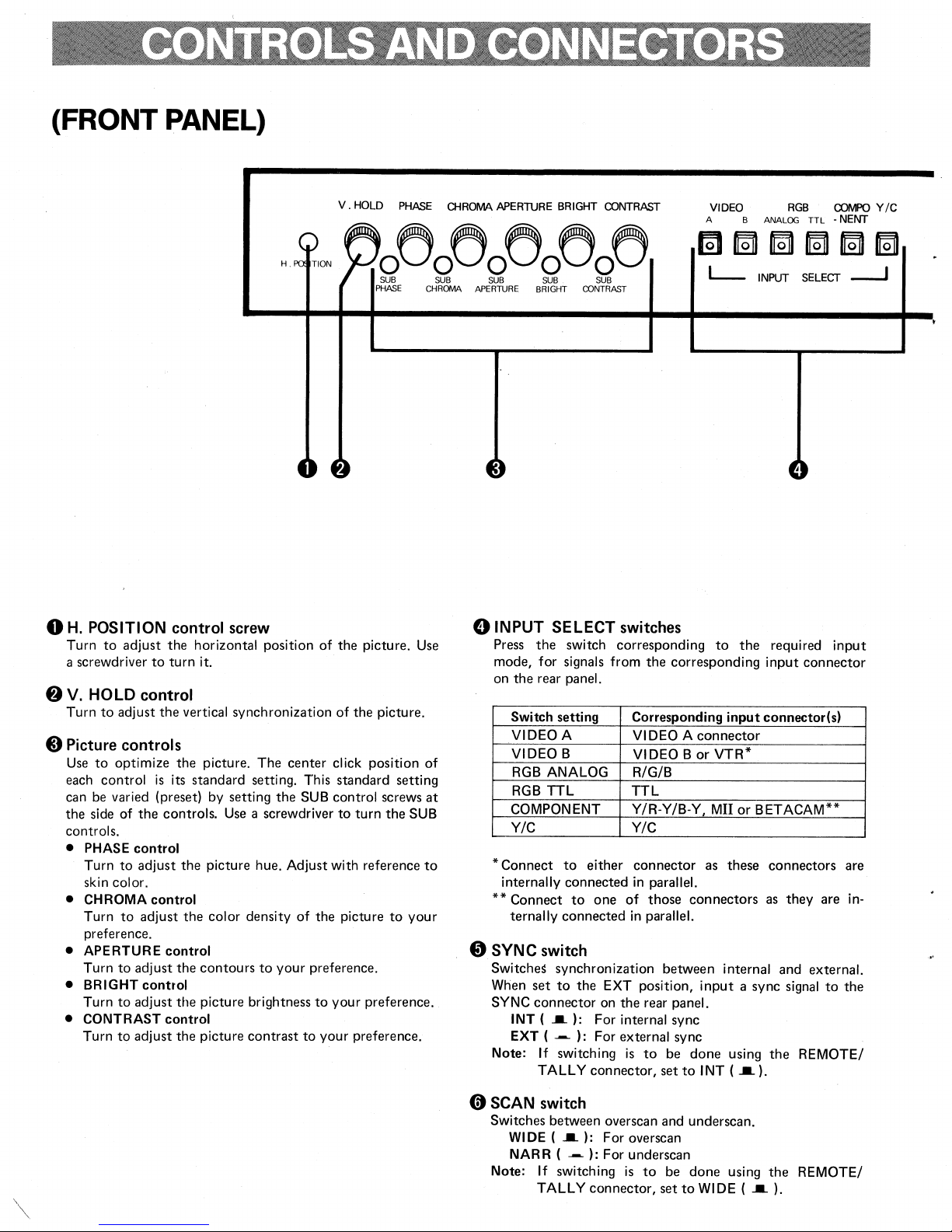
(FRONT PANEL)
V.
HOLD
PHASE
H.
TION
0~0~0~0~0~
SUB
PHASE
OIROMA
SUB SUB SUB SUB
CHROMA APERTURE
APERTURE
BRIGHT CONTRAST
BRIGHT
OONTRAST
VIDEO
A B
l__
ANALOG
INPUT
RGB
SELECT
TTL
COI'v1PO
•
NENT
___j
Y /C
0
H.
POSITION control
Turn
to
adjust
the
horizontal position
a screwdriver
8
V.
HOLD control
Turn
to
8
Picture
Use
to
each control
can be varied (preset) by setting
the
side
controls.
• PHASE
Turn
skin color.
• CHROMA
Turn
preference.
•
APERTURE
Turn
• BRIGHT
Turn
• CONTRAST
Turn
to
adjust
the
controls
optimize
is
of
the
control
to
adjust
control
to
adjust
to
adjust
control
to
adjust
to
adjust
turn
it.
vertical synchronization
the
picture. The
its standard setting. This standard setting
controls.
the
picture hue. Adjust with reference
the
color density
control
the
contours
the
picture brightness
control
the
picture
screw
Use
a screwdriver
to
contrast
center
the
of
your
of
the
of
click position
SUB
control screws
to
the
picture
preference.
to
your
to
your
picture.
the
picture.
turn
the
SUB
to
your
preference.
preference.
Use
of
at
to
0
INPUT SELECT
Press
the
switch corresponding
mode, for signals from
on
the
rear panel.
Switch setting
VIDEO A VIDEO A
VIDEO
RGB
RGB
COMPONENT Y/R-Y/8-Y,
Y/C
*Connect
internally connected
**Connect
ternally connected
0
SYNC
Switches
When
SYNC
INT
EXT (
Note: If
B
ANALOG
TTL
to
either
to
one
switch
synchronization between internal and external.
set
to
the
EXT position,
connector
(
_._
~
TALLY connector,
on
): For internal sync
) : For external sync
switching
switches
the
corresponding
Corresponding
VIDEO
R/G/B
TTL
Y/C
connector
in
of
in
the
is
parallel.
those
parallel.
rear
panel.
to
be
set
B
connectors
done
to
to
the
required
input
input
connector(s)
connector
or
VTR*
Mil
or
BETACAM**
as these connectors are
as
they
input
a sync signal
using
the
INT
(
_._
).
input
connector
are
to
REMOTE/
in-
the
0
SCAN
Switches between overscan and underscan.
Note: If
switch
WIDE
(
_._
):
NAR R (
~
) : For underscan
switching
TALLY connector,
For overscan
is
to
be
set
done
to
WIDE
using
(
_._
the
).
REMOTE/
Page 5

SYNC
INT
PULSE
CROSS
OFF
check
of
(
AFC
COLOR
NOR
CROSS
the
retrace period (sync
the
input
signal.
(
_._
) : For
~
) : For retrace period
SCAN
WIDE
fj
PULSE
To
phase
OFF
ON
check
«;)AFC
0
switch
Switches
circuitry
Note:
NOR
VAR (
The
"fast"
consult
the
AFC
to
correct
(
_._
):
For
~
): Fast or
"VAR"
(when shipped) and
your
COLOR/MONO
switch
Switches picture between
checking
Note:
white
COLOR
MONO (
If
balance,
(
_._
):
~
):
switching
TALLY connector,
I
R
G
ON ON
f@J1 f@J1
OFF OFF
f@J1
ON
OFF
B
.a
DEGAUSS
PUS
ON
I
I
switch
signal)
normal
picture
display
time
constant
the
skewed portion of
normal
(standard) condition
slow
of
condition
condition can be switched between
local dealer.
color
and monochrome for
etc.
For a color picture
For a
monochrome
is
to
be
done
set
to
COLOR
the
the
"slow".
picture
using
(
by delaying
horizontal
picture.
For
details,
the
REMOTE/
_._
).
PUSH·
the
sync
POWER
•
..rvc
41)
R/G/B switches
To
output
and B
adjustment
ON(•):
OFF
Hue/color
( 1)
Input
(2)
Turn
off.
(3)
Turn
controls so
shown
same brightness.
4D
DEGAUSS switch
Press
observed.
Degaussing
Keep this switch depressed for
this switch a second time, wait more
..
POWER
Press
again
or
eliminate individual colors
(blue))
()
~
of
in
the
hue or
Coloron
:
Color
density
a color bar
the
R and G color
(Only
B
will be
the
PHASE and
that
in
the
diagram have
to
demagnetize
switch/indicator
to
turn
the
to
turn
the
power off.
output,
color
density.
off
adjustment
signal.
outputs
displayed.)
CHROMA
all
color
the
power on. The indicator
(R (red), G (green)
for checking each
(.,
s
.~E;im~-ca>
5
a;
::.>-UCJ:2:a:iii
bars
the
Blue Blue
Same brightness
CRT
when
color patches are
approx.
than
10
10
color or for
"'
c:
E )
>
~
"' ., "'
Blue Blue
seconds. To use
minutes.
lights.
Press
8Tally
lamp
Lights when a
connector
MOTE/TALLY
tally signal
on
the
connector"
rear
is
panel.
input
to
the
(For
operation, see
on page 7.)
REMOTE/TALLY
0
"RE-
Page 6

{REAR
0
0
QaQ
0
0 0
oco
oco
0°0
0°0
oco
oco
o:o
PANEL)
------
D
§]
0
0
0
CJ
::]r==
l§~~
Y/C
r
VIDEO
OPEN
VTR
RGB
/TALLY
"'""'
MIT
IN
T~
Dlliii
0
~~~~
IN
our
C@T-<@l
Cf>EN
[][ll
75!l
©J.-t-<@J
EN
Lfiiii)
75Q
©J.--t-<@l
OPEN
[]Jill
75Q
<@-t-<@j
OPEN
DIIIIJ
75n
<@-t-<@
OPEN
DIIIIJ
75r.!
©J.-t-<@
~rnm
'"
DDID
?sn
1
2~~~
(@--y-(@
OPEN
(@--y-(@J
OPEN
DillD
75D:
©1-T-<@
EN
[][ll
75Q
BETAC.M
0
50H•
TTL
r-----'
Q
TTL
...
··:·:··
VI
1'----1
60Hz
ooooooooo
II/ODE
I
1111[]
I
OliT
AVTO
9N
0
4D
Power input connector
Connect
4DVI
Input
nected signal
Termination
~VIDEO
Input
connected signal
Termination
Note: This connector
to
an
AC
outlet
DEO
A
IN/OUT
connector
output
IN:
When
OUT: For bridged connection
switch
75
S1:
When there
OPEN: For bridged connection
BIN/OUT
connector
IN:
When
OUT: For bridged connection
switch
75
S1:
When there
OPEN: For bridged connection
with
the
equipment
connectors/Termination switch
for
composite video signal and bridge-con-
connector.
inputting
connectors/Termination switch
for
composi,te video signal and
output
inputting
VTR
connector. Therefore, do
to
both
with
the provided power cord.
a composite video signal
is
only
an
input
signal
connector.
a composite video signal
is
only
an
input
signal
is
internally
connectors at the
connected in
same
not
time.
bridge-
parallel
connect
4D
R/G/B
Input
connected signal
Note:
Sync
Sync
No
(Sync
Termination
8Y/R-Y/B-Y
IN/OUT
connectors
IN:
When
OUT: For bridged connection
Set
sync
signal
on green
signal
signal
input
75
S1:
OPEN: For bridged connection
connectors/Termination switches
for
output
inputting
the
SYNC
signal.
to
the
switch
When there
IN/OUT
switches
Input
connectors
connected signal
IN:
When
signals
OUT: For bridged connection
Note: This connector
the
Mil
not
connect
same
Termination switch
75
S1:
OPEN:
for
output
inputting
is
and
BET
equipment
time.
When there
For
bridged connection
R/G/8
connectors.
switch
SYNC
analog signals and
R,
G and 8 analog signals
as
are
only
follows
connector)
input
depending on
signals
SYNC
INT
EXT
connectors/Termination
component
connectors.
internally
ACAM
are
video signals
Y/R-Y/8-Y
connectors. Therefore,
to
only
component
connected
those connectors at
input
signals
in
bridge-
switch
(
_._
(
and
bridge-
paralle
the
)
~)
,"f.
video
with
do
the
Page 7

G)SYNC IN/OUT
Input
connectors
bridge-connected
video
signal
external genlock
IN:
When
OUT:
For
Termination switch
75
Q:
OPEN:
GY/C
fD
IN/OUT
Input
connector
format) and bridge-connected
IN:
When
OUT:
For
Termination switch
75
Q:
OPEN:
VTR
connector
Input
connector
ment
that
output
connector.
Notes:
• This connector
the
VIDEO
equipment
•
Bridged
connectors/Termination switch
for
sync (composite video)
signal
output
to
be
input
does
not
applications.
inputting
bridged connection
When there
For bridged connection
a sync signal
is
only
an
connectors/Termination switch
for
Y/C
separate video
signal
inputting
bridged connection
When there
For bridged connection
is
provided
B.
to
both connectors at the
output
Y/C
separate video
are
only
for
composite video
with
the
is
internally
IN
connector. Therefore, do
is
not
connected in
possible.
fBREMOTE/TALLY connector
For remote operation
VIDEO
MONO
[Connection diagram]
A/B,
the settings
switches,
and
.-------~--~V~ID~E~O~B
of
the
of
the
lighting
/Internal
of
the
/ / External
II
I
I
.-~----~N~AR~R~~~~--~
signal
connector.
contain a sync
input
output
input
same
input
SYNC, SCAN,
tally
Use
when the
signal
signal
signals (S-VHS
connector.
signals
signals
signal
from
equip-
type
of
8-pin VTR
parallel
not
connect
same
time.
switching between
COLOR/
lamp.
j
VIDEOA~CT
COLOR COLOR/MONO
MONO
WIDE
!NT
EXT
0
-
I
SCAN
SYNC
and
or
in
with
@)
Mil connector
Input
connector
Note: This connector
with
the Y /R-Y
Therefore, do
connectors at the
e
BET
ACAM
Input
connector
signals.
Notes:
• This connector
circuitry
switched
factory.
your
•
This connector
the
connect equipment
fiVf
switch
Use
to
"AUTO"
are
unstable,
~TTL
Input
with
a
Note:Set the
f)TTL
Set
according
nector.
1:
2:
is
to
To
local dealer.
Y/R-Y/B-Y
set
the
for
connector
connector
horizontal
puterconnected.
MODE
When connected
compatible
When connected
for
Mil
format
component video
is
internally
/B-Y
and BET
not
connect equipment
same
time.
connector
for
BET
ACAM
can
be
used
switched
Mil
use
vertical
automatic detection
set
to
for
scanning frequency
TTL
to
BETACAM.
when the
this connector
is
internally
and
to
scanning frequency.
"50
RGB
MODE
See"
monitor
connected in parallel
Mil
connectors. Therefore, do
these
connectors
Hz"
or
"60
TTL
signals. Connect a computer
switch depending on the com-
fi
TTL
switch
to
the computer connected
to
an
IBM
computer
to
a computer other than the above.
connected in
ACAM
format
component video
only
when the
The
is
shipped from the
(BETACAM),
at
of
50
or
Hz".
of
15.75
MODE
to
(with
CGA)
signals.
connectors.
to
internal
circuitry
the
same
Normally,
60
Hz.
If
kHz.
switch"
the
TTL
or
an
parallel
these
is
consult
with
not
time.
set
to
signals
below.
con-
IBM-
Tally lamp switch when
powered
internally
Tally lamp
powered
Notes:
•
For switching the
internal
•
When using this connector, the front-panel controls
should
and
external, consult
be
set
INPUT SELECT switch:
SYNC switch:
SCAN
switch:
COLOR/MONO
as
follows:
tally
switch:
lamp's
your
VIDEO
INT
WIDE
COLOR
switch when
externally
power source between
local dealer.
A
(•)
(•)
(•)
ON
OFF
Page 8

•
Be
sure
to
before connecting
•
Also refer
be
connected.
disconnect the power plug from the AC
to
other equipment.
to
the instruction manual
of
the equipment
I
outlet
to
-
Equipment
Y/C
(S-VHS)
Equipment
RGB
1=·1??~
I~
DODD
D
Equipment
component
that
separate video
that
analog signals
lL
DOD
DOD
DO~~~
.
·-
D
DDIOIOD
1010 DIOIDIOO
o
that
video
outputs
signals
outputs
-
:Til
--
~
0 0
outputs
signals
ID:
r---
I
Y/C
I
IN
OUT
I
I
I
I
I
I
I
_J
-·-,
I
I
I
I
I
I
I
Equipment
VTR
Remote
ment
j:</??~lc;;:nl
I~
00001
DIDIDCUIDIK::JIDDDD
Mil-format
(component
with
output
connector
control
0 0 0 0 0 0 0 0
0 0
...
o
lo
OIO[Jo
equipment
video
an
8-pin
equip.
GJ=
Ill
..-
~
~
signals)
L.---
Equipment
a sync
signal
that
outputs
•
When
using any
set
its termination switch
of
the
OUT
connectors (bridged output),
to
"OPEN".
BETACAM-format
ment
(component
signals)
Equipment
RGB
TTL
that
signals
equip.
video
outputs
Page 9

The
following
is
an
outline
of
the
circuitry
and connections, showing concepts,
it
is
not
a
circuit
diagram.
Composite
input connectors
Y
/C
input connector
Component video
input connectors
video
separate video
{
VIDEO
VIDEO
VTR
Y/C
y
R-Y
B-Y
A
B
IN
IN
IN
IN
IN
OUT
OUT
OUT
OUT
OUT
OPEN
Termination switch
75Q
OPEN
I
To~;M,;oo
75
Q
OPEN
I
To~;o.moo
75Q
OPEN
IT•~;M,;oo
switch
~;""
LOG
<(
m
0
INPUT
w
0
0
w
0
>
switch
>
RGB
TTL
~;""
Y/C
~
COMPONENT
RGB
A
NO
SELECT
RGB analog
connectors
RGB
TTL
connector
input
input
{
Mil
BETA
TTL
CAM
R
G
B
IN
@
IN
@
IN
@
=~
0
OUT
@
OUT
@
OUT
@
75Q
b
OPEN
I
Termination
switch
75Q,~
OPEN
1
T"m'"";'"
switch
·Termination swtich
"'!'""
Page 10

Type
Color
system
CRT
size
TTL
input
(HxV)
input
A/B)
input
input
input
Screen
Scanning frequency
Horizontal resolution
Power requirement
Power consumption
Composite video
(VIDEO
(VTR)
Y /C separate video
Component video inputs
(Y/R-V/8-Y)
(MIT)
(BETACAM)
R.G.B. analog
R.G.B.
Sync
External control connector
(REMOTE/TALLY)
Weight
Accessory
: Color video monitor
: NTSC system
:
19"
(measured diagonally), 90°
gun
deflection, in-ling
resolution CRT,
:
399x
296 mm
:(H)
15.75 kHz
(V)
50/60Hz
: More than 600 lines
: AC 120
: Max. 1.35 A, Avg. 86 W
: 8NC x 4 (2
1.0 Vp·p, 75 ohms, negative sync
Termination switch provided
: 8-pin VTR connector x 1,
1.0 Vp-p, 75 ohms, negative sync
: 7 -pin connector x 2 ( 1
output)
Y:
C:
Termination switch provided
: 8NC x 6 (3
Y: 1 Vp-p, 75 ohms, negative sync
R-Y/8-Y: 0.7 Vp-p, 75 ohms
Termination switch provided
: 12-pin connextor x 1,
Y:
R-Y/8-Y: 0.7 Vp-p, 75 ohms
: 12-pin connector x 1
Y:
R-Y/8-Y: 0.7 Vp-p, 75 ohms
: 8NC x 6 (3
R/G/8:
Sync on
negative
: 9-pin D-sub connector x 1
: 8NC x 2
1 - 4 Vp-p, 75 ohms, negative;
(V8S) 1 Vp-p, 75 ohms, negative sync
Termination switch provided
: 7-pin connector x 1
: 83.8 lbs (33.3
: Power cord (approx.
V,
60 Hz
with
1 Vp-p, 75 ohms, negative sync
0.286
Vp-:p
with
1 Vp-p, 75 ohms, negative sync
1 Vp-p, 75 ohms, negative sync
with
0.7 Vp-p, 75 ohms
green
1 Vp-p, 75 ohms,
(1
with
kg)
medium-high
tri-dot
pitch 0.4 mm
bridged
(burst), 75 ohms
bridged output)
bridged output)
bridged output)
with
2m)
output).
bridged
x 1
Pin Assignment
VTR
connector
(Input)
4 3 2
5 6 7 8
MII·BETACAM connectors
(Input)
11
Y /C connectors
IN
.•
4
,
3
Pin
No.
I
2
3
4
5
6
7
Pin No. Signal
I
2
3
4
5 -
6
7
8
Pin No. Signal
10
II
12
-
Composite video
-
-
GND
-
-
y
GNDlYl
R·Y
GND
B·Y
GND
OUT
7
,.
3 4
Signal
y
GND
(Y)
-
-
c
GND (C)
-
(R·Y)
(B-Y)
Design
and
specifications subject to change
without
notice.
TTL
connectors
(Input)
2 1
4
5
3
W#
9 8
7 6
Pin No. Signal
I
2
3
4
5
6
7
8 ±H SYNC
9
GND
GND
R
G
B
INTENSITY
GND
±V
SYNC
Page 11

Dimensions
co
en
N
(Unit:
mm)
401
·-
~
( F.ront legs) 370
-'1".
I
(Rear
legs) 390
449
T
-I
l
I
-
Page 12

·-
-
....
"'.
JVC
JVC PROFESSIONAL PRODUCTS COMPANY
21
DIVISION
41
Slater
Finchdene
OF
US
Drive,
Elmwood
JVC CANADA INC.
Square,
JVC CORP.
Park,
Scarborough
Ontario
N.J.
07407
M1
X 1
.
A7
-
-
..
·-
-
\1.
i!
j.
'\-
,.
-
-
-
-
-
-
 Loading...