

Page 1
SERVICE MANUAL
MICRO COMPONENT SYSTEM
MB16820043
UX-P400
Area suffix
B ------------------------------- U.K.
E ----------- Continental Europe
EN ------------ Northern Europe
EV -------------- Eastern Europe
A ------------------------- Australia
CA-UXP400SP-UXP400 SP-UXP400
TABLE OF CONTENTS
1 PRECAUTION. . . . . . . . . . . . . . . . . . . . . . . . . . . . . . . . . . . . . . . . . . . . . . . . . . . . . . . . . . . . . . . . . . . . . . . . . 1-3
2 SPECIFIC SERVICE INSTRUCTIONS . . . . . . . . . . . . . . . . . . . . . . . . . . . . . . . . . . . . . . . . . . . . . . . . . . . . . . 1-7
3 DISASSEMBLY . . . . . . . . . . . . . . . . . . . . . . . . . . . . . . . . . . . . . . . . . . . . . . . . . . . . . . . . . . . . . . . . . . . . . . . 1-8
4 ADJUSTMENT . . . . . . . . . . . . . . . . . . . . . . . . . . . . . . . . . . . . . . . . . . . . . . . . . . . . . . . . . . . . . . . . . . . . . . . 1-31
5 TROUBLESHOOTING . . . . . . . . . . . . . . . . . . . . . . . . . . . . . . . . . . . . . . . . . . . . . . . . . . . . . . . . . . . . . . . . . 1-32
COPYRIGHT © 2004 VICTOR COMPANY OF JAPAN, LIMITED
No.MB168
2004/3
Page 2
SPECIFICATION
Amplifier section Output Power 40 W (20 W + 20 W) at 40 Ω (10% THD)
Speakers/Impedance 4Ω - 16Ω
Audio Input AUX:400 mV/50 kΩ
Tuner section FM tuning range 87.50 MHz - 108.00 MHz
AM (MW) tuning range 522 kHz - 1 629 kHz
CD player section Dynamic range 88 dB
Signal-to-noise ratio 93 dB
Wow and flutter Immeasurable
Cassette deck section Frequency response Normal (type I):50 Hz - 14 000 Hz
Wow and flutter 0.15% (WRMS)
Speakers Speaker units 10 cm cone × 1
Impedance 4 Ω
Dimensions (approx.) 145 mm × 230 mm × 191 mm (W/H/D)
Mass (approx.) 1.8 kg each
General Power requirement AC 230 V 50 Hz
Power consumption 50 W (at operation) 1.4 W (on standby)
Dimensions (approx.) 170 mm × 230 mm × 311 mm (W/H/D)
Mass (approx.) 4.5 kg
Designs and Specifications are subject to change without notice.
1-2 (No.MB168)
Page 3
SECTION 1
PRECAUTION
1.1 Safety Precautions
(1) This design of this product contains special hardware and
many circuits and components specially for safety purposes. For continued protection, no changes should be made
to the original design unless authorized in writing by the
manufacturer. Replacement parts must be identical to
those used in the original circuits. Services should be performed by qualified personnel only.
(2) Alterations of the design or circuitry of the product should
not be made. Any design alterations of the product should
not be made. Any design alterations or additions will void
the manufacturers warranty and will further relieve the
manufacture of responsibility for personal injury or property
damage resulting therefrom.
(3) Many electrical and mechanical parts in the products have
special safety-related characteristics. These characteristics are often not evident from visual inspection nor can the
protection afforded by them necessarily be obtained by using replacement components rated for higher voltage, wattage, etc. Replacement parts which have these special
safety characteristics are identified in the Parts List of Service Manual. Electrical components having such features
are identified by shading on the schematics and by ( ) on
the Parts List in the Service Manual. The use of a substitute
replacement which does not have the same safety characteristics as the recommended replacement parts shown in
the Parts List of Service Manual may create shock, fire, or
other hazards.
(4) The leads in the products are routed and dressed with ties,
clamps, tubings, barriers and the like to be separated from
live parts, high temperature parts, moving parts and/or
sharp edges for the prevention of electric shock and fire
hazard. When service is required, the original lead routing
and dress should be observed, and it should be confirmed
that they have been returned to normal, after reassembling.
(5) Leakage shock hazard testing
After reassembling the product, always perform an isolation check on the exposed metal parts of the product (antenna terminals, knobs, metal cabinet, screw heads,
headphone jack, control shafts, etc.) to be sure the product
is safe to operate without danger of electrical shock.Do not
use a line isolation transformer during this check.
• Plug the AC line cord directly into the AC outlet. Using a
"Leakage Current Tester", measure the leakage current
from each exposed metal parts of the cabinet, particularly any exposed metal part having a return path to the
chassis, to a known good earth ground. Any leakage current must not exceed 0.5mA AC (r.m.s.).
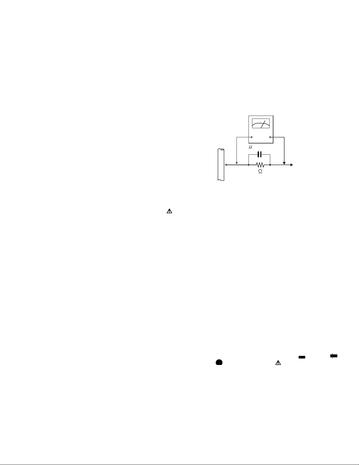
• Alternate check method
Plug the AC line cord directly into the AC outlet. Use an
AC voltmeter having, 1,000Ω per volt or more sensitivity
in the following manner. Connect a 1,500Ω 10W resistor
paralleled by a 0.15µF AC-type capacitor between an ex-
posed metal part and a known good earth ground.
Measure the AC voltage across the resistor with the AC
voltmeter.
Move the resistor connection to each exposed metal
part, particularly any exposed metal part having a return
path to the chassis, and measure the AC voltage across
the resistor. Now, reverse the plug in the AC outlet and
repeat each measurement. Voltage measured any must
not exceed 0.75 V AC (r.m.s.). This corresponds to 0.5
mA AC (r.m.s.).
AC VOLTMETER
(Having 1000
ohms/volts,
or more sensitivity)
0.15 F AC TYPE
Place this
probe on
1500 10W
Good earth ground
1.2 Warning
(1) This equipment has been designed and manufactured to
meet international safety standards.
(2) It is the legal responsibility of the repairer to ensure that
these safety standards are maintained.
(3) Repairs must be made in accordance with the relevant
safety standards.
(4) It is essential that safety critical components are replaced
by approved parts.
(5) If mains voltage selector is provided, check setting for local
voltage.
1.3 Caution
Burrs formed during molding may be left over on some parts
of the chassis.
Therefore, pay attention to such burrs in the case of preforming repair of this system.
1.4 Critical parts for safety
In regard with component parts appearing on the silk-screen
printed side (parts side) of the PWB diagrams, the parts that are
printed over with black such as the resistor ( ), diode ( )
and ICP ( ) or identified by the " " mark nearby are critical
for safety. When replacing them, be sure to use the parts of the
same type and rating as specified by the manufacturer.
(This regulation dose not Except the J and C version)
each exposed
metal part.
(No.MB168)1-3
Page 4
1.5 Safety Precautions (U.K only)
(1) This design of this product contains special hardware and many circuits and components specially for safety purposes. For con-
tinued protection, no changes should be made to the original design unless authorized in writing by the manufacturer. Replacement parts must be identical to those used in the original circuits.
(2) Any unauthorised design alterations or additions will void the manufacturer's guarantee; furthermore the manufacturer cannot
accept responsibility for personal injury or property damage resulting therefrom.
(3) Essential safety critical components are identified by ( ) on the Parts List and by shading on the schematics, and must never
be replaced by parts other than those listed in the manual. Please note however that many electrical and mechanical parts in
the product have special safety related characteristics. These characteristics are often not evident from visual inspection. Parts
other than specified by the manufacturer may not have the same safety characteristics as the recommended replacement parts
shown in the Parts List of the Service Manual and may create shock, fire, or other hazards.
(4) The leads in the products are routed and dressed with ties, clamps, tubings, barriers and the like to be separated from live parts,
high temperature parts, moving parts and/or sharp edges for the prevention of electric shock and fire hazard. When service is
required, the original lead routing and dress should be observed, and it should be confirmed that they have been returned to
normal, after re-assembling.
1.5.1 Warning
(1) Service should be performed by qualified personnel only.
(2) This equipment has been designed and manufactured to meet international safety standards.
(3) It is the legal responsibility of the repairer to ensure that these safety standards are maintained.
(4) Repairs must be made in accordance with the relevant safety standards.
(5) It is essential that safety critical components are replaced by approved parts.
(6) If mains voltage selector is provided, check setting for local voltage.
Burrs formed during molding may be left over on some parts of the chassis. Therefore,
pay attention to such burrs in the case of preforming repair of this system.
1-4 (No.MB168)
Page 5
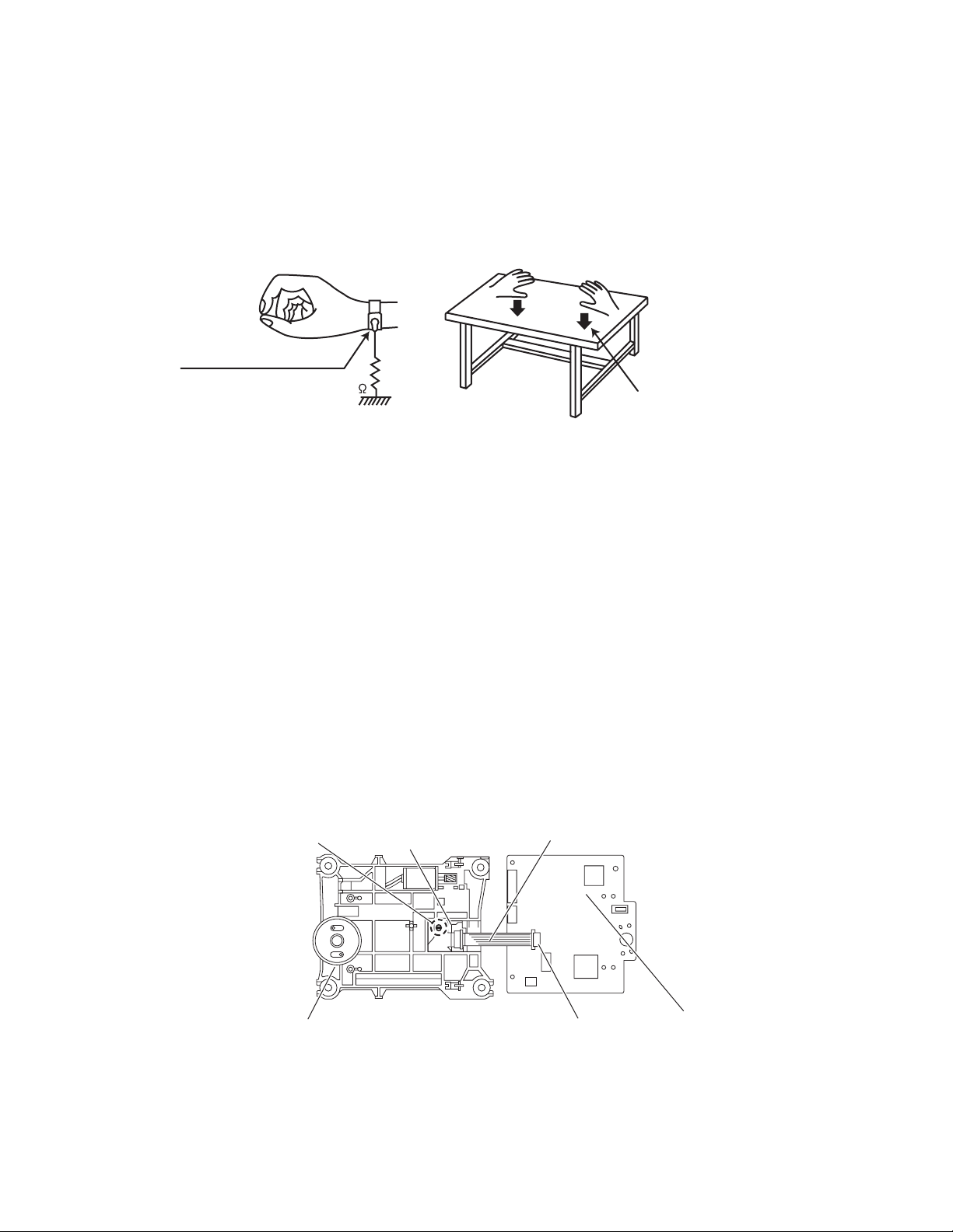
1.6 Preventing static electricity
Electrostatic discharge (ESD), which occurs when static electricity stored in the body, fabric, etc. is discharged, can destroy the laser
diode in the traverse unit (optical pickup). Take care to prevent this when performing repairs.
1.6.1 Grounding to prevent damage by static electricity
Static electricity in the work area can destroy the optical pickup (laser diode) in devices such as laser products.
Be careful to use proper grounding in the area where repairs are being performed.
(1) Ground the workbench
Ground the workbench by laying conductive material (such as a conductive sheet) or an iron plate over it before placing the
traverse unit (optical pickup) on it.
(2) Ground yourself
Use an anti-static wrist strap to release any static electricity built up in your body.
(caption)
Anti-static wrist strap
1M
Conductive material
(conductive sheet) or iron palate
(3) Handling the optical pickup
• In order to maintain quality during transport and before installation, both sides of the laser diode on the replacement optical
pickup are shorted. After replacement, return the shorted parts to their original condition.
(Refer to the text.)
• Do not use a tester to check the condition of the laser diode in the optical pickup. The tester's internal power source can easily
destroy the laser diode.
1.7 Handling the traverse unit (optical pickup)
(1) Do not subject the traverse unit (optical pickup) to strong shocks, as it is a sensitive, complex unit.
(2) Cut off the shorted part of the flexible cable using nippers, etc. after replacing the optical pickup. For specific details, refer to the
replacement procedure in the text. Remove the anti-static pin when replacing the traverse unit. Be careful not to take too long a
time when attaching it to the connector.
(3) Handle the flexible cable carefully as it may break when subjected to strong force.
(4) I t is not possible to adjust the semi-fixed resistor that adjusts the laser power. Do not turn it.
1.8 Attention when traverse unit is decomposed
*Please refer to "Disassembly method" in the text for the pickup unit.
• Apply solder to the short land sections before the flexible wire is disconnected from the connecto on the servo board. (If the flexible
wire is disconnected without applying solder, the pickup may be destroyed by static electricity.)
• In the assembly, be sure to remove solder from the short land sections after connecting the flexible wire.
Short land section
CD pickup
Card wire
Traverse mechanism assembly
CN601
CD servo board
(No.MB168)1-5
Page 6
1.9 Important for laser products
!
1.CLASS 1 LASER PRODUCT
2.DANGER : Invisible laser radiation when open and inter
lock failed or defeated. Avoid direct exposure to beam.
3.CAUTION : There are no serviceable parts inside the
Laser Unit. Do not disassemble the Laser Unit. Replace
the complete Laser Unit if it malfunctions.
4.CAUTION : The CD,MD and DVD player uses invisible
laser radiation and is equipped with safety switches which
prevent emission of radiation when the drawer is open and
the safety interlocks have failed or are defeated. It is
dangerous to defeat the safety switches.
5.CAUTION : If safety switches malfunction, the laser is able
to function.
6.CAUTION : Use of controls, adjustments or performance of
procedures other than those specified here in may result in
hazardous radiation exposure.
Please use enough caution not to
see the beam directly or touch it
in case of an adjustment or operation
check.
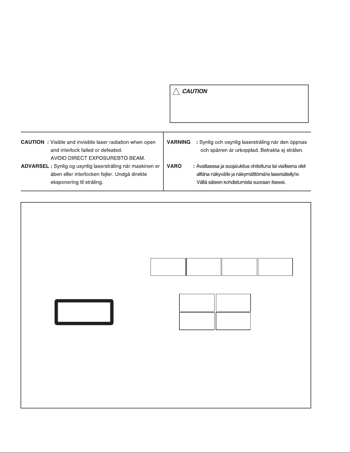
REPRODUCTION AND POSITION OF LABELS
WARNING LABEL
CAUTION : Visible and Invisible
laser radiation when open and
interlock failed or defeated.
AVOID DIRECT EXPOSURE TO
BEAM. (e)
CLASS 1
LASER PRODUCT
ADVARSEL : Synlig og usynlig
laserstråling når maskinen er
åben eller interlocken fejeler.
Undgå direkte eksponering til
stråling. (d)
CAUTION : Visible and Invisible
laser radiation when open and
interlock failed or defeated.
AVOID DIRECT EXPOSURE TO
BEAM. (e)
VARNING : Synlig och
osynling laserstrålning när
den öppnas och spärren är
urkopplad. Betrakta ej
strålen. (s)
VARNING : Synlig och
osynling laserstrålning när
den öppnas och spärren är
urkopplad. Betrakta ej
strålen. (s)
VARO : Avattaessa ja suojalukitus
ohitettuna tai viallisena olet alttiina
näkyvälle ja näkymättömälle
lasersäteilylle. Vältä säteen
kohdistumista suoraan itseesi. (f)
ADVARSEL : Synlig og usynlig
laserstråling når maskinen er
åben eller interlocken fejeler.
Undgå direkte eksponering til
stråling. (d)
VARO : Avattaessa ja suojalukitus
ohitettuna tai viallisena olet alttiina
näkyvälle ja näkymättömälle
lasersäteilylle. Vältä säteen
kohdistumista suoraan itseesi. (f)
1-6 (No.MB168)
Page 7

SECTION 2
SPECIFIC SERVICE INSTRUCTIONS
This service manual does not describe SPECIFIC SERVICE INSTRUCTIONS.
(No.MB168)1-7
Page 8
SECTION 3
DISASSEMBLY
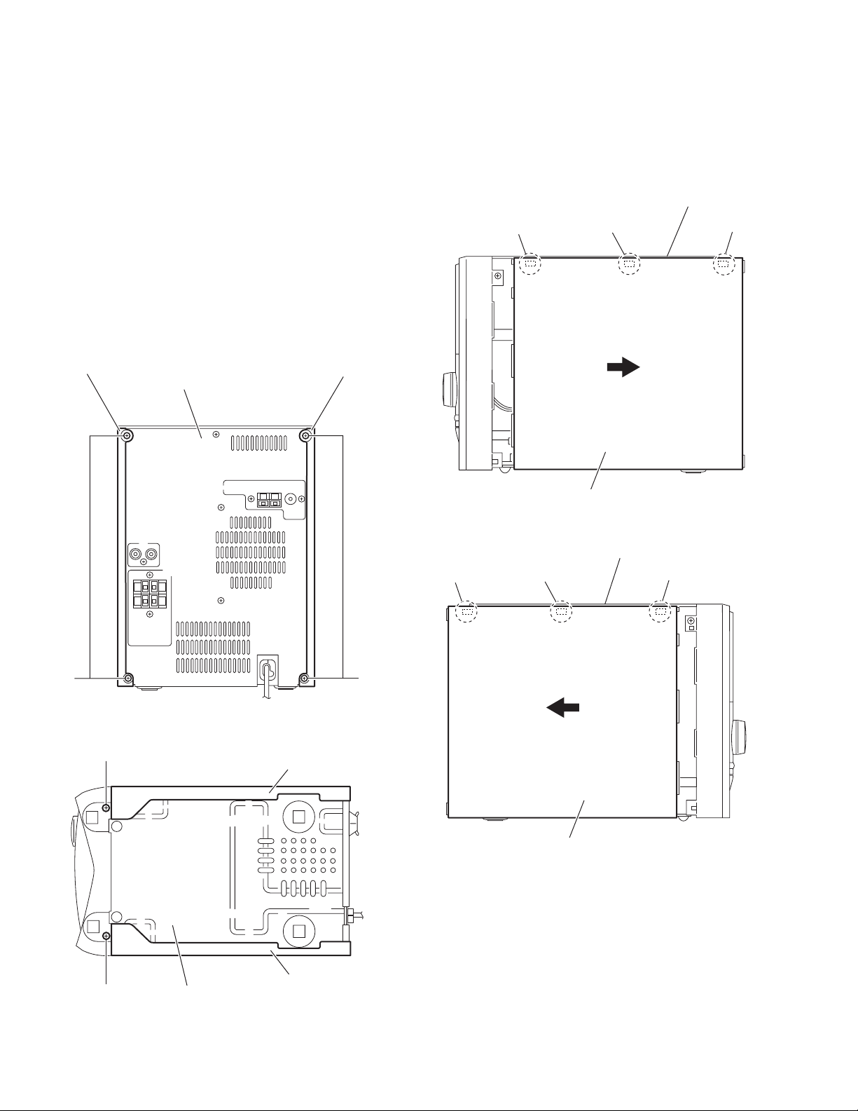
3.1 Main body section
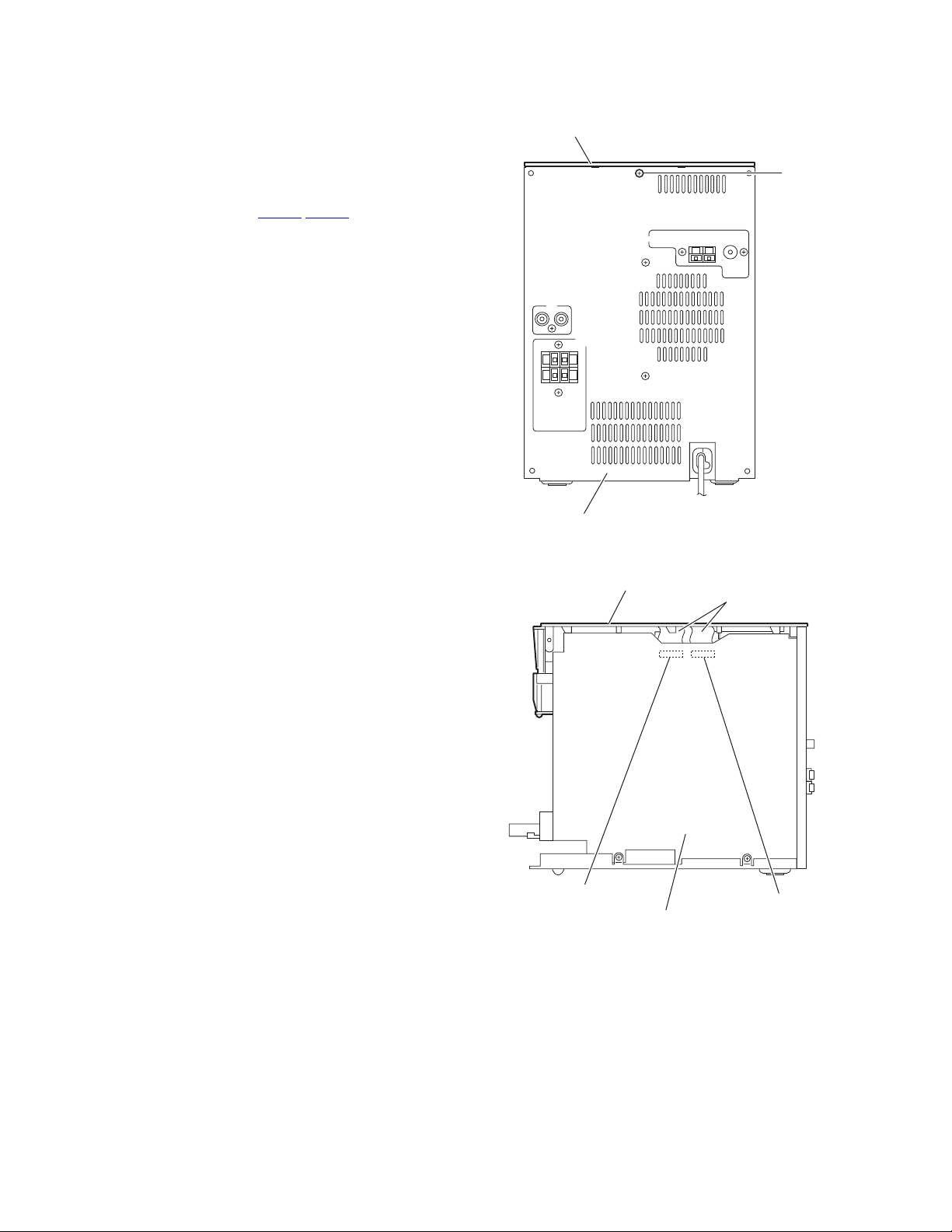
3.1.1 Removing the side panels L/R
(See Figs.1 to 4)
(1) From the back side of the main body, remove the four
screws A attaching the side panels L/R to the rear panel.
(See Fig.1.)
(2) From the bottom side of the main body, remove the two
screws B attaching the side panels L/R to the bottom chassis. (See Fig.1.)
(3) From the both sides of the main body, release the engage-
ment sections (a,b) of the side panels L/R from the top cover assembly in the direction of the arrow. (See Figs.3 and
4.)
(4) Remove the side panels L/R toward this side.
Top cover assembly
a
a
a
Side panel R
A
B
Rear panel
Fig.1
Side panel L
Side panel R
A
Side panel R
Fig.3
Top cover assembly
b
b
b
B
1-8 (No.MB168)
Side panel L
Fig.4
Side panel L
Bottom chassis
Fig.2
Page 9
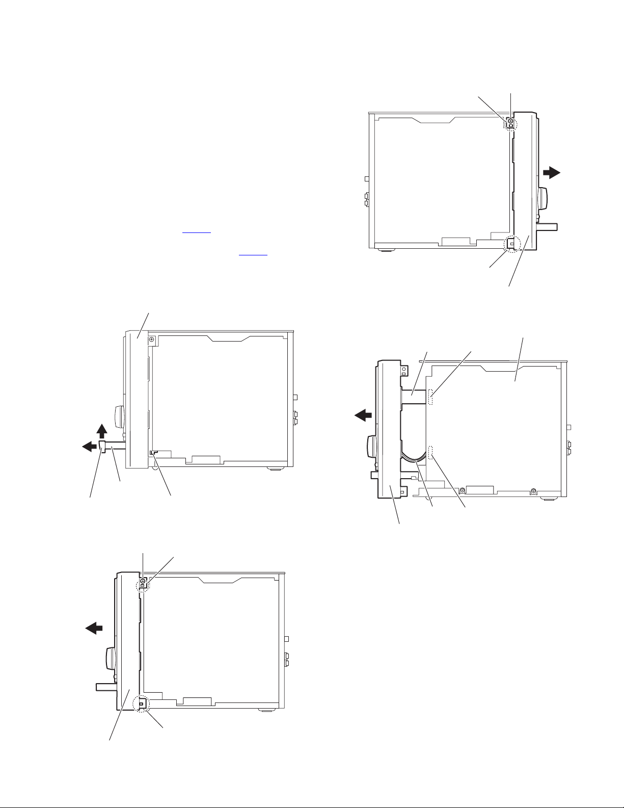
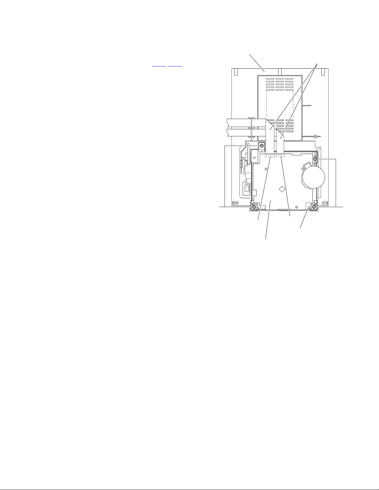
3.1.2 Removing the front panel assembly
(See Figs.5 to 8)
• Prior to performing the following procedures, remove the side
panels L/R.
(1) From the right side of the main body, push the slide cam
and pull the tray assembly out of the main body in the direction of the arrow 1. (See Fig.5.)
(2) Remove the tray fitting from the tray assembly in the direc-
tion of the arrow 2. (See Fig.5.)
(3) From the both sides of the main body, remove the two
screws C attaching the front panel assembly. (See Figs.6
and 7.)
(4) Release the two claws c and claws d to draw out the front
panel assembly in the direction of the arrow. (See Figs.6
and 7.)
(5) From the right side of the main body, disconnect the card
wire from the connector CN730
Fig.8.)
(6) Disconnect the wire from the connector CN271
board. (See Fig.8.)
(7) Remove the front panel assembly in the direction of the ar-
row. (See Fig.8.)
Front panel assembly
on the main board. (See
on the main
c
Front panel assembly
Fig.7
CN730Card wire
C
d
Main board
2
1
Tray assembly
Tray fitting
C
Slide cam
Fig.5
c
Wire
Front panel assembly
CN271
Fig.8
d
Front panel assembly
Fig.6
(No.MB168)1-9
Page 10
3.1.3 Removing the top cover assembly
(See Figs.9 and 10)
• Prior to performing the following procedures, remove the side
panels L/R and front panel assembly.
(1) From the back side of the main body, remove the screw D
attaching the top cover assembly to the rear panel. (See
Fig.9.)
(2) From the right side of the main body, disconnect the card
wires from the connectors (CN701
board. (See Fig.10.)
(3) Take out the top cover assembly from the main body.
,CN702) on the main
Top cover assembly
D
Rear panel
Fig.9
Top cover assembly
CN702
Main board
Fig.10
Card wires
CN701
1-10 (No.MB168)
Page 11
3.1.4 Removing the cassette mechanism assembly
(See Fig.11)
• Prior to performing the following procedures, remove the side
panels L/R, front panel assembly and top cover assembly.
(1) From the bottom side of the top cover assembly, discon-
nect the card wires from the connectors (CN33
the head amplifier board.
(2) Remove the four screws E attaching the cassette mecha-
nism assembly and take out the cassette mechanism assembly from the top cover assembly.
,CN34) on
Top cover assembly
Card wires
E
CN34
Head amplifier board
CN33
Cassette mechanism assembly
Fig.11
E
(No.MB168)1-11
Page 12

3.1.5 Removing the tuner
(See Figs.12 and 13)
• Prior to performing the following procedures, remove the side
panel L.
(1) From the back side of the main body, remove the two
screws F attaching the tuner to the rear panel. (See
Fig.12.)
(2) Disconnect the card wire from the connector CN1
tuner. (See Fig.13.)
on the
F
Rear panel
Card wire
Tuner
Fig.12
CN1
Fig.13
1-12 (No.MB168)
Page 13

3.1.6 Removing the rear panel
(See Fig.14)
• Prior to performing the following procedures, remove the side
panels L/R.
(1) From the back side of the main body, remove the six
screws G attaching the rear panel.
(2) Release the engagement sections e and remove the rear
panel.
(3) Disconnect the wire from the connector CN711
board.
Reference:
After connecting the wire to the connector CN711
with the wire holder.
3.1.7 Removing the fan (See Figs.14 and 15)
• Prior to performing the following procedures, remove the side
panels L/R and rear panel.
(1) From the outside of the rear panel, remove the two screws
H attaching the fan bracket to the rear panel. (See Fig.14.)
(2) From the inside of the rear panel, move the fan bracket in
the direction of the arrow to release the engagement sections (f,g). (See Fig.15.)
(3) Remove the fan bracket from the rear panel and remove
the fan. (See Fig.15.)
on the main
, fix the wire
CN711
Wire
holder
Main board
Wire
G
G
e
Rear panel
e
H
Fig.14
f
Fan
Fan bracket
Rear panel
Fig.15
g
(No.MB168)1-13
Page 14

3.1.8 Removing the main board
(See Fig.16)
• Prior to performing the following procedures, remove the side
panels L/R, front panel assembly, top cover assembly, tuner
and rear panel.
(1) From the right side of the main body, remove the two
screws J attaching the main board.
(2) Remove the main board toward this side and disconnect
the connector CN200
(3) From the forward side of the main board, disconnect the
card wires from the connectors (CN210
on the main board.
,CN221).
CN210
Main board
3.1.9 Removing the power supply board
(See Fig.17)
• Prior to performing the following procedures, remove the side
panel L and rear panel.
(1) From the left side of the main body, remove the screw K at-
taching the power supply board.
(2) Remove the power supply board toward this side and dis-
connect the connector CN104
(3) From the forward side of the power supply board, discon-
nect the wires from the connectors (CN101
CN103).
Reference:
When attaching the power supply board, insert the section h of
the power supply board in the hole of the bottom chassis before attaching the screw K.
on the power supply board.
, CN102,
CN102
CN101
h
CN200
CN103
J
Card wire
Fig.16
K
J
CN221
Power supply board
CN104
1-14 (No.MB168)
Fig.17
Page 15
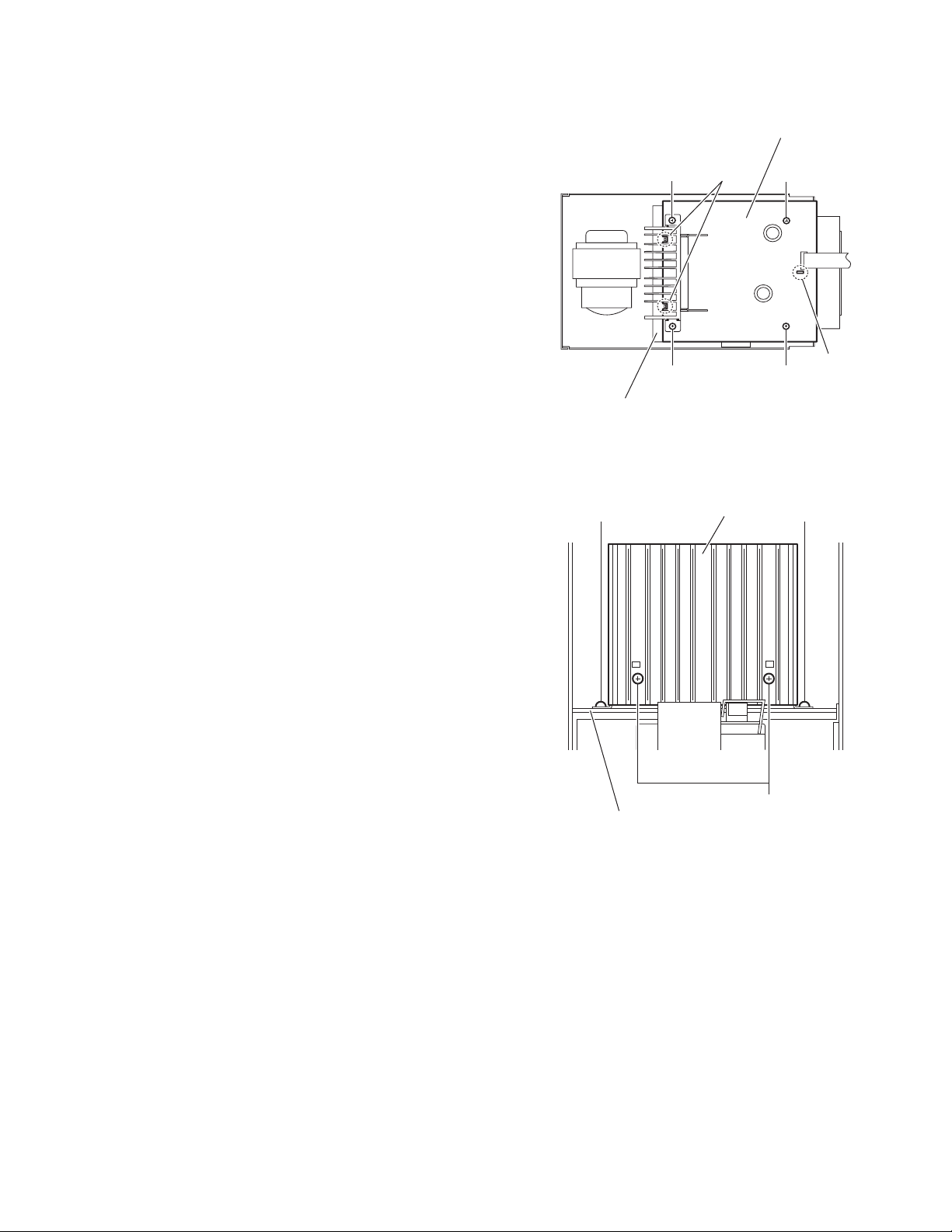
3.1.10 Removing the power amplifier board
(See Fig.18)
• Prior to performing the following procedures, remove the side
panels L/R, front panel assembly, top cover assembly, tuner,
rear panel, main board and power supply board.
(1) From the top side of the main body, remove the four screws
L attaching the power amplifier board.
(2) Lift the power amplifier board and remove it from the en-
gagement sections (i,j) of the shield case.
3.1.11 Removing the heat sink
(See Fig.19.)
• Prior to performing the following procedure, remove the side
panels L/R, front panel assembly, top cover assembly and rear
panel.
(1) From the top side of the main body, remove the two screws
M attaching the heat sink on the power amplifier board.
(2) From the side of the power amplifier board, remove the two
screws N attaching the heat sink.
Power amplifier board
L
i
L
LL
Shield case
Fig.18
M M
Heat sink
j
Power amplifier board
Fig.19
N
(No.MB168)1-15
Page 16

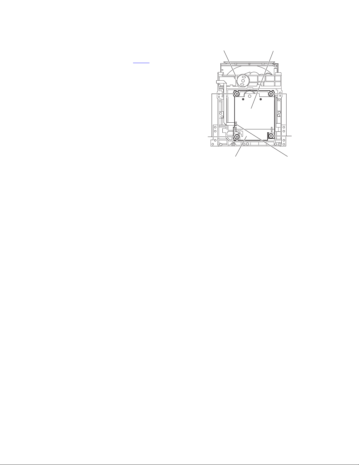
3.1.12 Removing the CD mechanism assembly
(See Figs.20 and 21)
• Prior to performing the following procedures, remove the side
panels L/R, front panel assembly, top cover assembly, tuner,
rear panel, main board and power supply board.
(1) From the top side of the main body, remove the four screws
P attaching the shield case to the bottom chassis. (See
Fig.20.)
Reference:
When attaching the shield case on the bottom chassis,
align the projections (k,m,n) of the bottom chassis in the
holes of the shield case. (See Fig.20.)
(2) Take out the shield case with the power amplifier board
from the bottom chassis.
(3) Remove the three screws Q attaching the CD mechanism
assembly to the bottom chassis. (See Fig.21.)
P
Shield case
k
Bottom chassis
P
m
Power amplifier board
CD mechanism assembly
Bottom chassis
n
P
Fig.20
Q
Q
1-16 (No.MB168)
Fig.21
Page 17

3.1.13 Removing the transformer
(See Figs.22 and 23)
• Prior to performing the following procedures, remove the side
panels L/R, front panel assembly, top cover assembly and rear
panel.
(1) From the forward side of the power supply board, discon-
nect the wires from the connectors (CN102
Fig.22.)
Reference:
Remove the power supply board as required. (See
Fig.17.)
(2) From the top side of the main body, remove the four screws
R attaching the transformer. (See Fig.23.)
,CN103). (See
CN102
Transformer
Power supply board
CN103
Fig.22
R
R
R
Fig.23
(No.MB168)1-17
Page 18

3.1.14 Removing the FL board
(See Fig.24)
• Prior to performing the following procedures, remove the side
panels L/R and front panel assembly.
(1) From the inside of the front panel assembly, remove the
four screws S attaching the FL board.
(2) Take out the FL board from the front panel assembly and
disconnect the card wire from the connector CN751
FL board.
Reference:
When attaching the FL board, align the projections p of the
front panel assembly in the holes of the FL board.
on the
CN751
Card
wire
S
FL board
p
S
p
S
S
Front panel assembly
Fig.24
1-18 (No.MB168)
Page 19

3.1.15 Removing the switch board
(See Figs.25 and 26)
• Prior to performing the following procedures, remove the side
panels L/R and front panel assembly.
(1) From the front side of the front panel assembly, pull out the
volume knob. (See Fig.25.)
(2) From the inside of the front panel assembly, remove the
ten screws T attaching the switch board. (See Fig.26.)
(3) Take out the switch board from the front panel assembly
and disconnect the card wire from the connector CN760
the switch board. (See Fig.26.)
Reference:
When attaching the switch board, align the projections q of the
front panel assembly in the holes of the switch board. (See
Fig.26.)
on
Front panel assembly
Volume knob
Fig.25
Card wire
T
Switch board
CN760
q
T
q
T
Fig.26
(No.MB168)1-19
Page 20

3.1.16 Removing the headphone jack board
(See Fig.27)
• Prior to performing the following procedure, remove the side
panels L/R and front panel assembly.
(1) From the inside of the front panel assembly, remove the
screw U attaching the headphone jack board.
Reference:
After attaching the headphone jack board, fix the wire with the
spacer.
Spacer
Wire
U
Headphone jack board
Fig.27
Front panel assembly
1-20 (No.MB168)
Page 21

3.2 CD mechanism section
• Remove the CD mechanism assembly from the main body.
(See "3.1.12 Removing the CD mechanism assembly".)
3.2.1 Removing the tray assembly
(See Figs.1 to 3)
(1) From the right side of the CD mechanism assembly, push
the slide cam and pull the tray assembly out of the CD
mechanism assembly in the direction of the arrow. (See
Fig.1)
(2) From the top side of the CD mechanism assembly, remove
the two screws A attaching the leaf spring to the bushing
and remove the leaf spring. (See Fig.2)
(3) Remove the bushing of the tray assembly from the projec-
tion a on the CD mechanism assembly and move the tray
assembly in the direction of the arrow. (See Fig.3)
(4) Remove the claw b of the tray assembly from the CD
mechanism assembly and take out the tray assembly. (See
Fig.3)
Tray assembly CD mechanism assembly
Slide cam
Fig.1
Leaf spring
Bushing
A
CD mechanism assembly
Fig.2
Projection a
Claw b
CD mechanism assembly
Fig.3
Bushing
Tray assembly
(No.MB168)1-21
Page 22
3.2.2 Removing the traverse mechanism assembly
(See Figs.4)
(1) From the bottom side of the CD mechanism assembly, re-
move the four screws B attaching the traverse mechanism
assembly.
(2) Disconnect the card wire from the connector CN602
CD servo board and take out the CD traverse mechanism
assembly with the CD servo board.
on the
CD mechanism assembly
CD servo board
B
Traverse mechanism assembly
Fig.4
B
CN602
1-22 (No.MB168)
Page 23

3.2.3 Removing the CD servo board
(See Figs.5 and 6)
• Remove the traverse mechanism assembly.
(1) From the bottom side of the traverse mechanism assem-
bly, remove the solders from the solder sections c. (See
Fig.5)
(2) Remove the wire (yellow) from the solder sections d. (See
Fig.5)
(3) Remove the wire (white) from the solder sections e. (See
Fig.5)
(4) Remove the two screws C attaching the CD servo board.
(See Fig.5)
(5) Remove the CD servo board from the claws f in the direc-
tion of the arrow and turn the CD servo board over. (See
Fig.5)
(6) Solder the short land sections g on the CD pickup. (See
Fig.6)
(7) Release the lock of the connector CN601
board in the direction of the arrow and disconnect the card
wire. (See Fig.6)
Caution:
• Solder the short land sections g on the CD pickup before disconnecting the card wire from the connector CN601
CD servo board. If the card wire is disconnected without attaching solder, the CD pickup may be destroyed by static
electricity. (See Fig.6)
• When attaching the CD servo board, be sure to remove solders from the short land sections g after connecting the card
wire to the connector CN601
Fig.6)
on the CD servo board. (See
on the CD servo
on the
Claw f
Solder section c
CD servo board
Wire (yellow)
CC
Wire (white)
Solder
section d
Solder
section e
Claw f
Traverse mechanism assemblyCD servo board
Fig.5
CN601
CD pickup
Short land section g
Lock
Traverse mechanism assembly
Fig.6
(No.MB168)1-23
Page 24
3.2.4 Removing the CD pickup
(See Figs.7 to 9)
• Remove the traverse mechanism assembly.
(1) From the top side of the traverse mechanism assembly, re-
move the screw D attaching the shaft holder. (See Fig.7)
(2) Release the joint h and take out the shaft holder. (See
Fig.7)
(3) Remove the two screws E attaching the rack arm and take
out the rack arm. (See Fig.8)
(4) Remove the feed middle gear and remove the screw shaft
of the CD pickup from the section i on the traverse mechanism assembly. (See Fig.8)
(5) Remove the CD pickup from the section j of the traverse
mechanism assembly and take out the CD pickup with the
screw shaft. (See fig.8)
(6) Pull the screw shaft out of the CD pickup. (See Fig.8)
(7) From the bottom side of the CD pickup, solder the short
land sections k on the CD pickup. (See Fig.9)
(8) Release the lock of the connector on the CD pickup in the
direction of the arrow and disconnect the card wire. (See
Fig.9)
Caution:
• Solder the short land sections k on the CD pickup before disconnecting the card wire from the connector on the CD pickup. If the card wire is disconnected without attaching solder,
the CD pickup may be destroyed by static electricity. (See
Fig.9)
• When attaching the CD pickup, be sure to remove solders
from the short land sections k after connecting the card wire
to the connector on the CD pickup. (See Fig.9)
Traverse mechanism assembly
Feed middle gear
Screw shaft
DJoint h
Shaft holder
Fig.7
Rack arm
E
Section i
1-24 (No.MB168)
CD pickup
Short land section k
CD pickup Connector Card wire
Section j
Fig.8
Fig.9
Page 25
3.2.5 Attaching the CD pickup
(See Figs.7 to 10)
• See "3.2.4 Removing the CD pickup".
(1) Remove solders from the short land sections k after con-
necting the card wire to the connector on the CD pickup.
(See Fig.9)
(2) Attach the shaft. (See Fig.8)
(3) Align the CD pickup to the section j of the traverse mecha-
nism assembly first, and set the screw shaft of the CD pick-
up in the sections i of the traverse mechanism assembly.
(See Fig.8.)
(4) Attach the rack arm and feed middle gear. (See Fig.8)
(5) Attach the shaft holder. (See Fig.7)
(6) Turn the SS gear in the direction of the arrow 1 to move the
CD pickup in the direction of the arrow 2. (See Fig.10)
SS gear
1
2
3.2.6 Removing the feed motor
(See Figs.5, 7 and 11)
• Remove the traverse mechanism assembly.
(1) From the top side of the traverse mechanism assembly, re-
move the wire (yellow) from the solder sections d on the
CD servo board. (See Fig.5)
(2) Remove the wire (white) from the solder sections e on the
CD servo board. (See Fig.5)
(3) Remove the screw D attaching the shaft holder and take
out the shaft holder. (See Fig.7)
(4) Remove the feed middle gear and remove the screw E at-
taching the feed motor. (See Fig.11)
(5) Take out the feed motor from the traverse mechanism as-
sembly.
Reference:
When attaching the feed motor, pass the wires through the
section m on the traverse mechanism assembly. (See Fig.11)
Traverse mechanism assembly
Fig.10
E
Feed motor
Wires
Pickup
Section m
Feed middle gear
Traverse mechanism assembly
Fig.11
(No.MB168)1-25
Page 26
3.2.7 Removing the CD loading switch board
(See Fig.12)
(1) From the bottom side of the CD mechanism assembly, dis-
connect the card wire from the connector CN1 on the CD
loading switch board.
(2) Remove the wires from the solder section n on the CD
loading switch board.
(3) Lift the CD loading switch board while pressing the claw p
of the CD mechanism assembly in the direction of the arrow and remove it from the section q.
Reference:
• Put the wires on the section r after attaching the CD loading
switch board to the CD mechanism assembly.
• Fix the claw p on the CD mechanism assembly with bonds
after attaching the CD loading switch board.
3.2.8 Removing the motor
(See Figs.12 and 13)
• Remove the tray assembly.
(1) From the bottom side of the CD mechanism assembly, re-
move the wires from the solder section n on the CD loading
switch board. (See Fig.12)
(2) From the top side of the CD mechanism assembly, remove
the belt from the motor pulley. (See Fig.13)
Note:
Take care not to attach grease on the belt.
(3) Remove the two screws F attaching the motor to the CD
mechanism assembly and take out the motor from the bottom side of the CD mechanism assembly. (See Fig.13)
Reference:
Put the wires on the section r after attaching the motor to the
CD mechanism assembly. (See Fig.12)
CD loading switch board
Wire
Solder
section n
CN1
section q section r
CD mechanism assembly
F
Claw p
CD mechanism assembly
Fig.12
Belt
Fig.13
Motor pulley
1-26 (No.MB168)
Page 27

3.3 Cassette mechanism assembly
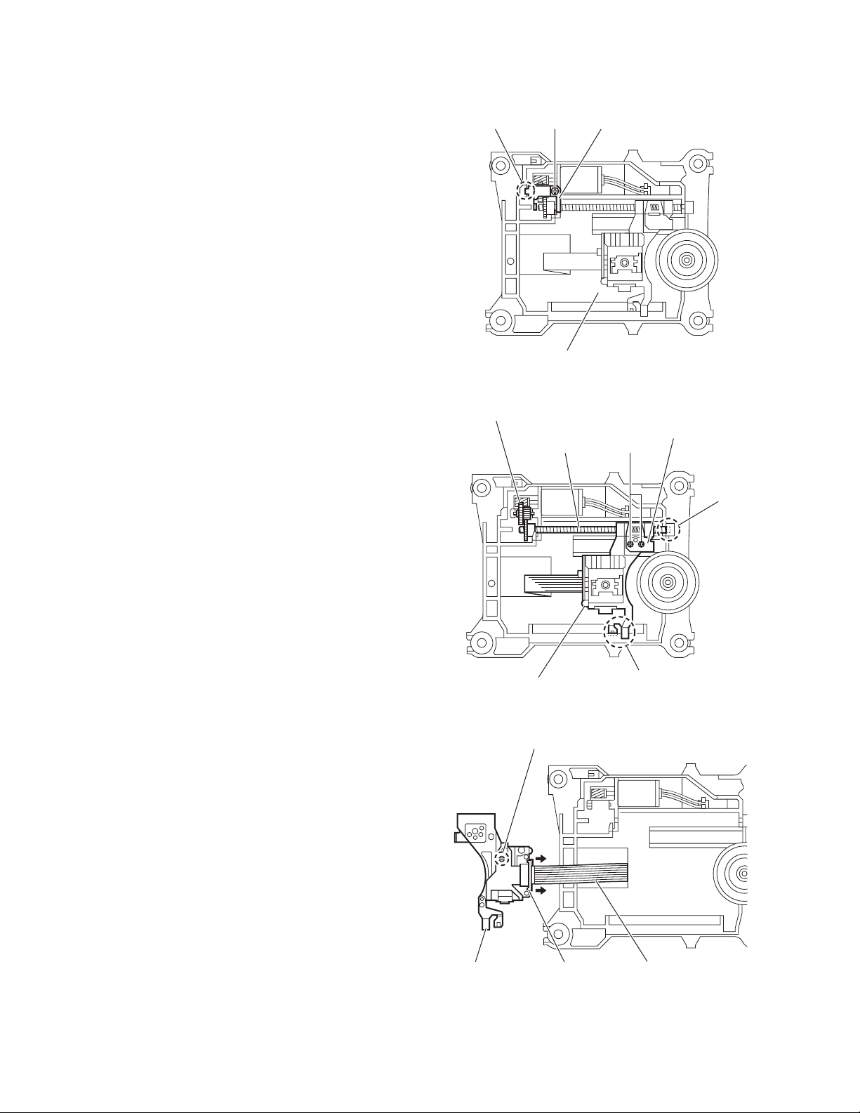
3.3.1 Removing the Play/Record & Clear head
(See Fig.1~3)
(1) While moving the trigger arm on the right side of the head
mount in the direction of the arrow, turn the flywheel R
counterclockwise until the head mount comes ahead and
clicks.
(2) The head turns counterclockwise as you turn the flywheel
R counterclockwise (See Fig.2 and 3).
(3) Disconnect the flexible wire from connector CN31
head amplifier & mechanism control board.
(4) Remove the spring from the back of the head.
(5) Loosen the azimuth screw for reversing attaching the head.
(6) Remove the head on the front side of the head mount.
on the
Cassette mechanism assembly
Fig.1
Head
Fly wheelR
Trigger armHead mount
Flexible wire
Fly wheel R
Fig.2
Azimuth screw
Head
for reversing
Spring
CN31
Head amplifer & mecha control board
Fig.3
(No.MB168)1-27
Page 28

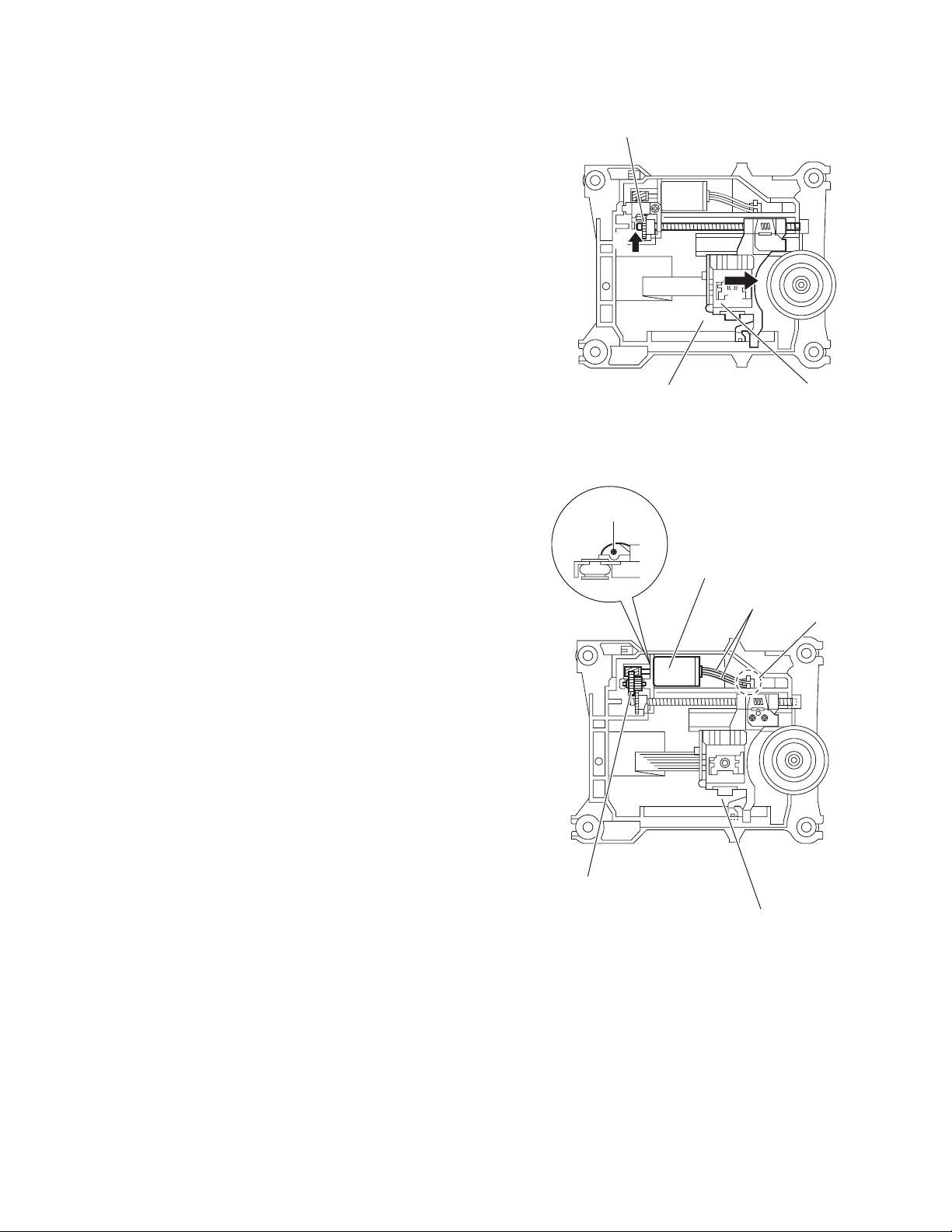
3.3.2 Removing the head amplifier & mechanism control board
(See Fig.4)
(1) Turn over the cassette mechanism assembly and remove
the three screws A attaching the head amplifier & mechanism control board.
(2) Disconnect the flexible wire from connector CN31
head amplifier & mechanism control board.
(3) Disconnect connector CN32
anism control board from connector CN1
board.REFERENCE: If necessary, unsolder the 4-pin wire
soldered to the main motor.
3.3.3 Removing the main motor
(See Fig.4~7)
(1) Remove the two screws B .
(2) Half raise the motor and remove the capstan belt from the
motor pulley.
ATTENTION:
Be careful to keep the capstan belt from grease. When reassembling, refer to Fig.6 and 7 for attaching the capstan belt.
Head amplifier & mecha control board
of the head amplifier & mech-
on the reel pulse
on the
Main motor assembly
Capstan belt
Fig.5
Main motor assembly
CN31
Flexible wire
A
AA
Fig.4
CN32
4pin wire
B
Main motor assembly
Motor pulley
Capstan belt
Fig.6
Main motor assembly
Fly wheel
1-28 (No.MB168)
Capstan belt
Motor pulley
Fig.7
Page 29
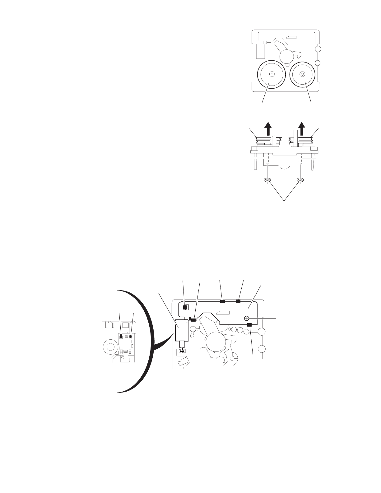
3.3.4 Removing the flywheel
(See Fig.8, 9)
• Prior to performing the following procedure, remove the head
amplifier & mechanism control board and the main motor assembly.
(1) From the front side of the cassette mechanism, remove the
slit washers attaching the capstan shaft L and R. Pull out
the flywheels backward.
Fly wheel R Fly wheel L
Fig.8
Fly wheel R
Capstan shaft R Capstan shaft L
Slit washer
Fig.9
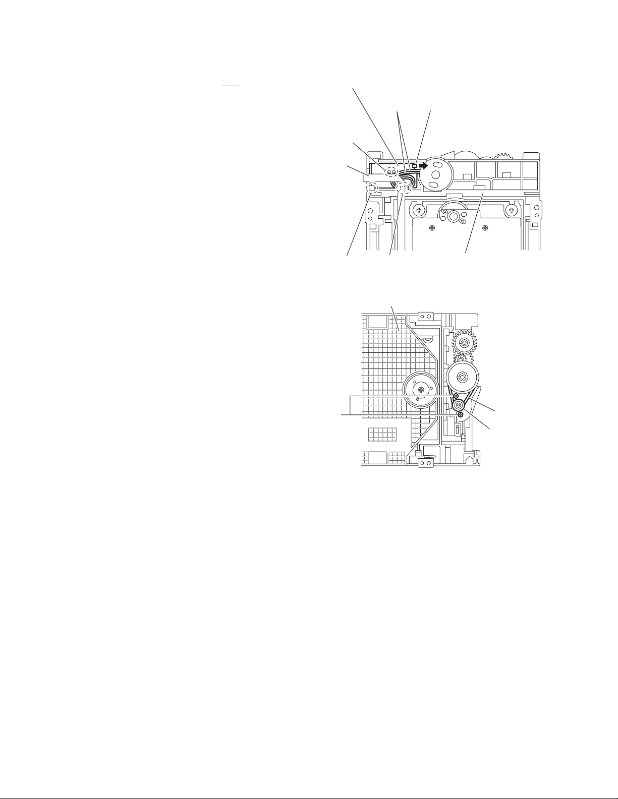
3.3.5 Removing the reel pulse board and solenoid
(See Fig.10)
• Prior to performing the following procedure, remove the head amplifier & mechanism control board.
(1) Remove the screw C.
(2) Release the tab a, b, c, d and e retaining the reel pulse board.
(3) Release the tab f and g attaching the solenoid on the reel pulse board.
(4) The reel pulse board and the solenoid come off.
Fly wheel L
bc
a
Solenoid
g
f
d
Reel pulse board
C
e
Fig.10
(No.MB168)1-29
Page 30
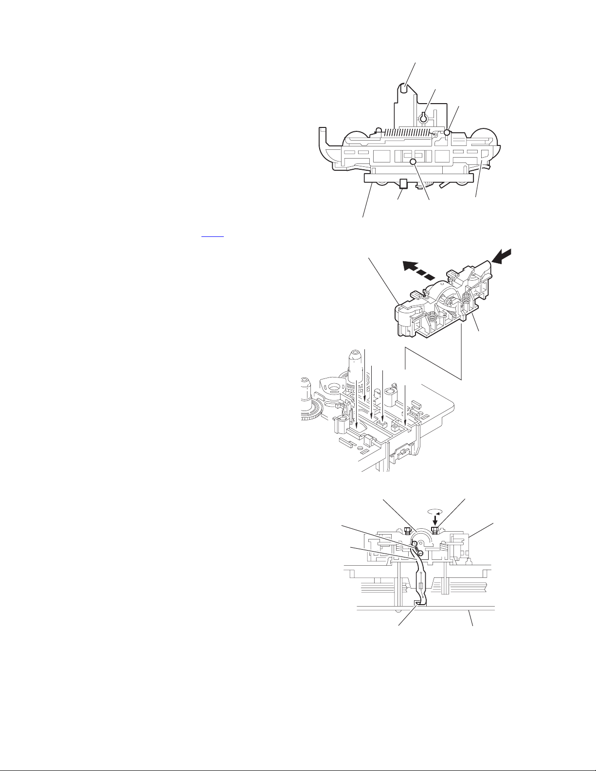
3.3.6 Reattaching the Play/ Record & Clear head
r
r
(See Fig.11~13)
(1) Reattaching the head mount assembly.
a) Change front of the direction cover of the head
mount assembly to the left (Turn the head forward).
b) Fit the bosses O', P', Q', U' and V' on the head mount
assembly to the holes P and V, the slots O, U and Q
of the mechanism sub assembly (See Fig.11 to 13).
CAUTION:
To remove the head mount assembly, turn the direction
cover to the left to disengage the gear. If the gear can not
be disengaged easily, push up the boss Q' slightly and
raise the rear side of the head mounts slightly to return
the direction lever to the reversing side.
(2) Tighten the azimuth screw for reversing.
(3) Reattach the spring from the back of the Play/ Record &
Clear head.
(4) Connect the flexible wire to connector CN31
amplifier & mechanism control board.
on the head
U' Q'
Head mount assembly
Head mount assembly
O'
Fig.11
P'
P'
V'
V'
Direction cove
Spring
Flexible wire
V
O
P
Q
Head
Direction cove
U
Fig.12
Azimuth screw for reversing
Head mount
1-30 (No.MB168)
CN31
Fig.13
Head amplifier &
mechanism control board
Page 31
4.1 Jigs and test instruments
• Remote controller
4.2 Adjustment and check method
4.2.1 Initialize all data to the factory setting
SECTION 4
ADJUSTMENT
4.2.4 Fan motor ON/OFF check
While pressing the [STOP] , [STANDBY/ON]
and [10] keys on the remote controller, insert the
AC power cord of the main unit in an outlet.
FL indication
COLD
Initialize is complete.
4.2.2 Confirmation of the system micro computer
While pressing the [STOP] , [STANDBY/ON]
and [2] keys on the remote controller, insert the
AC power cord of the main unit in an outlet.
FL indication
08 02 E
or
09 00 E
Setup is complete.
While pressing the [STOP] , [STANDBY/ON]
and [9] keys on the remote controller, insert the
AC power cord of the main unit in an outlet.
Fan motor is rotating.
Setup is complete.
4.2.3 FL all lighting-up check
While pressing the [STOP] , [STANDBY/ON] and
[SLEEP] keys on the remote controller, insert the
AC power cord of the main unit in an outlet.
FL indication
All of the FL displays light up.
Setup is complete.
(No.MB168)1-31
Page 32

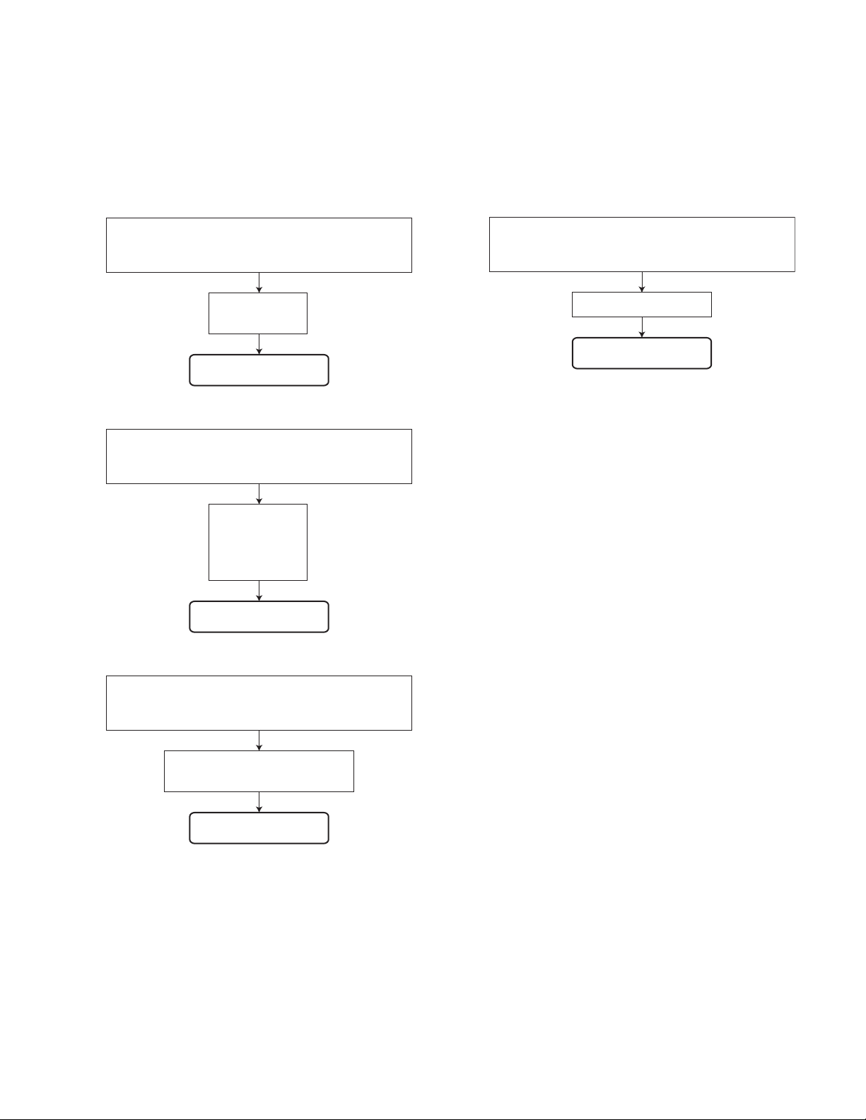
TROUBLESHOOTING
5.1 Flow of functional operation untill TOC read (CD)
Power ON
Disc play Key
Automatic tuning of FO offset and TE offset
SECTION 5
Slider turns REST
SW ON.
Laser ON
Detection of disc
Check Point
Confirm that the voltage at
the pin68 of IC251 is 0V.
(ON: 0V)
Tracking error waveform at TOC reading
IC601
20pin(TEOUT)
Approx.
1.4V
VREF
Disc status
to rotate
Approx. 3sec
Tracking
servo
off status
Automatic measurement
of TE amplitude and
automatic tuning of TE
balance
Tracking
servo
on status
Disc to be
braked to stop
TOC reading
finishes
500mv/div
2ms/div
Fig.1
Automatic measurement of
Focus S-curve amplitude
Disc is rotated
Focus servo ON
(Tracking servo ON)
Automatic measurement of
Tracking error amplitude
Automatic tuning of
Tracking error balance
Automatic tuning of
Focus error balance
Automatic tuning of
Focus error gain
Confirm that the Focus error
S-curve signal at the pin32 of
IC651 is approx. 1.4Vp-p.
Confirm that the signal from
pin22 of IC651 is 0V as a accelerated
pulse during approx. 640ms.
Confirm the waveform of the
Tracking error signal at the
pin20 of IC601(one side of
R604) (See Fig.1.)
1-32 (No.MB168)
Automatic tuning of
Tracking error gain
TOC reading
Play a disc
Confirm the eye-pattern
at the pin5 of IC601
Page 33

5.2 Maintenance of laser pickup (CD)
(1) Cleaning the pick up lens
Before you replace the pick up, please try to clean the lens
with a alcohol soaked cotton swab.
(2) Life of the laser diode
When the life of the laser diode has expired, the following
symptoms will appear.
• The level of RF output (EFM output : ampli tude of eye
pattern) will below.
5.3 Replacement of laser pickup (CD)
Turn of the power switch and, disconnect the
power cord.
Replace the pickup with a normal one. (Refer
to "Pickup Removal" on the previous page)
Is RF output
0.9 0.22Vp-p?
NO
Replace it.
YES
O.K
(3) Semi-fixed resistor on the APC PC board
The semi-fixed resistor on the APC printed circuit board
which is attached to the pickup is used to adjust the laser
power. Since this adjustment should be performed to
match the characteristics of the whole optical block, do not
touch the semi-fixed resistor.
If the laser power is lower than the specified value, the laser diode is almost worn out, and the laser pickup should
be replaced.
If the semi-fixed resistor is adjusted while the pickup is
functioning normally, the laser pickup may be damaged
due to excessive current.
Plug the power cord in, and turn the power on.
At this time, check that the laser emits for
about 3 seconds and the objective lens moves
up and down.
Note: Do not observe the laser beam directly.
Play a disc.
Check the eye-pattern at 5pin of IC601.
Finish.
(No.MB168)1-33
Page 34

VICTOR COMPANY OF JAPAN, LIMITED
AV & MULTIMEDIA COMPANY AUDIO/VIDEO SYSTEMS CATEGORY 10-1,1chome,Ohwatari-machi,Maebashi-city,371-8543,Japan
(No.MB168)
Printed in Japan
WPC
 Loading...