

Page 1
MB049200311
SERVICE MANUAL
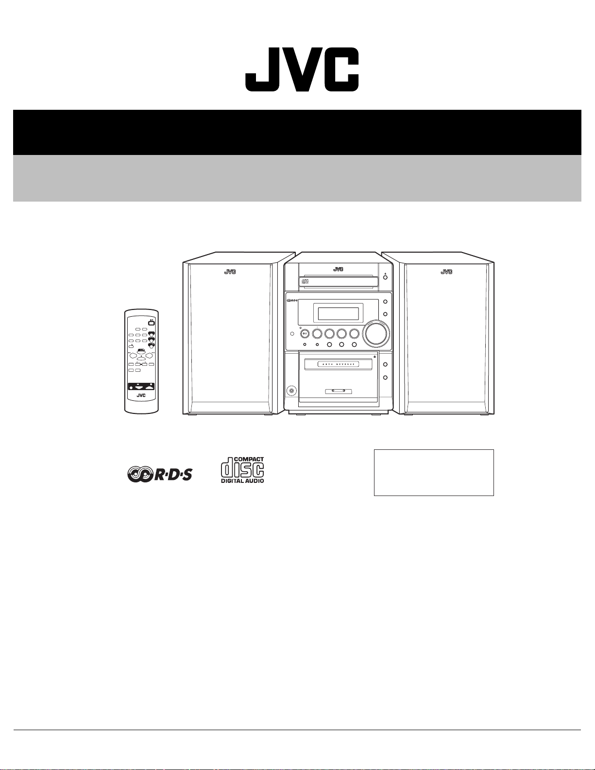
MICRO COMPONENT SYSTEM
UX-P30
CD-R/RW PLAYBACK
SLEEP
DISPLAY
REPEATRANDOMPROG
AUTO
SOUND
FM MODE
PRESET
MODE
CD
CD
CANCEL MULTI KEY SET
PTY
DISPLAY
/EON
MODE
AHB
VOLUME
RM-SUXP3R REMOTE CONTROL
MICRO COMPONENT SYSTEM UX-P30
STANDBY/ON
AUX
FM/AM
TAPE
STANDBY
CD
TAPE
FM/AM
/
CLOCK TIMER
PHONES
AUX
SOUND
AHB PRO
U
L
M
O
E
V
+
Ð
REV.MODE
REC
SP-UXP30 SP-UXP30
CA-UXP30
Area Suffix
B --------------------------- U.K.
E ------- Continental Europe
EN --------- Northern Europe
TABLE OF CONTENTS
1 Precautions . . . . . . . . . . . . . . . . . . . . . . . . . . . . . . . . . . . . . . . . . . . . . . . . . . . . . . . . . . . . . . . . . . . . . . . . . . 1-3
2 SPECIFIC SERVICE INSTRUCTIONS. . . . . . . . . . . . . . . . . . . . . . . . . . . . . . . . . . . . . . . . . . . . . . . . . . . . . . 1-7
3 DISASSEMBLY . . . . . . . . . . . . . . . . . . . . . . . . . . . . . . . . . . . . . . . . . . . . . . . . . . . . . . . . . . . . . . . . . . . . . . . 1-8
4 ADJUSTMENT . . . . . . . . . . . . . . . . . . . . . . . . . . . . . . . . . . . . . . . . . . . . . . . . . . . . . . . . . . . . . . . . . . . . . . . 1-21
5 TROUBLESHOOTING . . . . . . . . . . . . . . . . . . . . . . . . . . . . . . . . . . . . . . . . . . . . . . . . . . . . . . . . . . . . . . . . . 1-25
COPYRIGHT © 2003 VICTOR COMPANY OF JAPAN, LIMITED
No.MB049
2003/11
Page 2

SPECIFICATION
Amplifier Output Power 44 W (22 W + 22 W) at 4 Ω (MAX.)
40 W (20 W + 20 W) at 4 Ω (10 % THD)
Audio input sensitivity/Impedance (at 1 kHz) AUX : 400 mV/48 kΩ
Speakers/Impedance 4 Ω - 16 Ω
Tuner FM tuning range 87.50 MHz - 108.00 MHz
AM (MW) tuning range 522 kHz - 1 629 kHz
CD player Dynamic range 85 dB
Signal-to-noise ratio 90 dB
Wow and flutter Immeasurable
Cassette deck Frequency response Normal (type I) : 50 Hz - 14 000 Hz
Wow and flutter 0.15 % (WRMS)
Speaker Speaker units Woofer : 8 cm cone × 1
Tweeter : 2 cm cone × 1
Impedance 4 Ω
Dimensions (approx.) 160 mm × 256 mm × 197 mm (W/H/D)
Mass (approx.) 2.1 kg each
General Power requirement AC 230 V, 50 Hz
Power consumption 50 W (at operation)
3.8 W (on standby)
Dimensions (approx.) 505 mm × 256 mm × 294 mm (W/H/D)
Mass (approx.) 8.5 kg
Design and specifications are subject to change without notice.
1-2 (No.MB049)
Page 3
SECTION 1
PRECAUTION
1.1 Safety Precautions
(1) This design of th is product contains special hardw are and
many circuits and components specially for safety purposes. For continued protection, no changes should be made
to the original design unless authorized in writing by the
manufacturer. Replacement parts must be identical to
those used in the original circuits. Services should be performed by qualified personnel only.
(2) Alterations of the design or circuitry of the product should
not be made. Any design alterations of the product should
not be made. Any design alterations or additions will void
the manufacturers warranty and will further relieve the
manufacture of responsibility for personal injury or property
damage resulting therefrom.
(3) Many electrical and mechanical parts in the products have
special safety-related characteristics. These characteristics are often not evident from visual inspection nor can the
protection afforded by them necessarily be obtained by using replacement components rated for higher voltage, wattage, etc. Replacement parts which have these special
safety characteristics are identified in the Parts List of Service Manual. Electrical components having such features
are identified by shading on the schematics and by ( ) on
the Parts List in the Service Manual. The use of a substitute
replacement which does not have the same safety characteristics as the recommended replacement parts shown in
the Parts List of Service Manual may create shock, fire, or
other hazards.
(4) The leads in the products are routed and dressed with ties,
clamps, tubings, barriers and the like to be separated from
live parts, high temperature parts, moving parts and/or
sharp edges for the prevention of electric shock and fire
hazard. When service is required, the original lead routing
and dress should be observed, and it should be confirmed
that they have been returned to normal, after reassembling.
(5) Leakage shock hazard testing
After reassembling the product, always perform an isolation check on the exposed metal parts of the product (antenna terminals, knobs, metal cabinet, screw heads,
headphone jack, control shafts, etc.) to be sure the product
is safe to operate without danger of electrical shock.Do not
use a line isolation transformer during this check.
• Plug the AC line cord directly into the AC ou tlet. Using a
"Leakage Current Tester", measure the leakage current
from each exposed metal parts of the cabinet, particularly any exposed metal part having a return path to the
chassis, to a known good earth ground. Any leakage current must not exceed 0.5mA AC (r.m.s.).
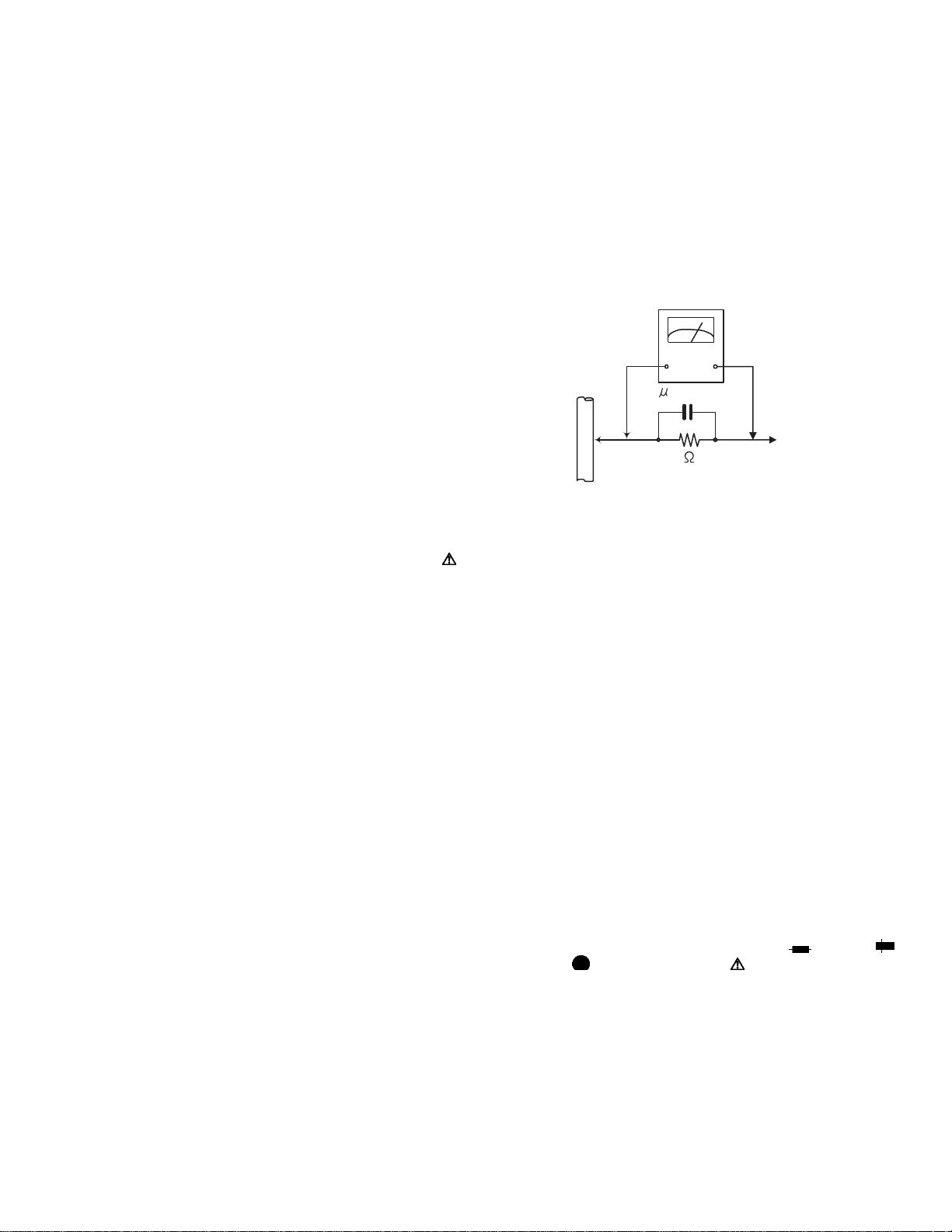
• Alternate check method
Plug the AC line cord directly into the AC outlet. Use an
AC voltmeter having, 1,000Ω per volt or more sensitivity
in the following manner. Connect a 1,500Ω 10W resistor
paralleled by a 0.15µF AC-type capacitor between an exposed metal part and a known good earth ground.
Measure the AC voltage across the resistor with the AC
voltmeter.
Move the resistor connection to each exposed metal
part, particularly any exposed metal part having a return
path to the chassis, and measure the AC voltage across
the resistor. Now, reverse the plug in the AC outlet and
repeat each measurement. Voltage measured any must
not exceed 0.75 V AC (r.m.s.). This corresponds to 0.5
mA AC (r.m.s.).
AC VOLTMETER
(Having 1000
ohms/volts,
or more sensitivity)
0.15 F AC TYPE
Place this
probe on
Good earth ground
1.2 Warning
(1) This equipment has been designed and manufactured to
meet international safety standards.
(2) It is the legal resp onsibility of the repairer to ensure that
these safety standards are maintained.
(3) Repairs must be made in accordance with the relevant
safety standards.
(4) It is essential that safety critical compone nts are replaced
by approved parts.
(5) If mains voltage selector is provided, check setting for local
voltage.
1.3 Caution Burrs formed during molding may be left over on some parts
of the chassis.
Therefore, pay attention to such burrs in the case of preforming repair of this system.
1.4 Critical parts for safety
In regard with component parts appearing on the silk-screen
printed side (parts side) of the PWB diagrams, the parts that are
printed over with black such as the resistor ( ), diode ( )
and ICP ( ) or identified by the " " mark nearby are critical
for safety. When replacing them, be sure to use the parts of the
same type and rating as specified by the manufacturer.
(This regulation dose not Except the J and C version)
each exposed
metal part.
(No.MB049)1-3
Page 4
1.5 Safety Precautions (U.K only)
(1) This design of this product contains special hardware and many circuits and components specially for safety purposes. For con-
tinued protection, no changes should be made to the original design unless authorized in writing by the manufacturer. Replacement parts must be identical to those used in the original circuits.
(2) Any unauthorised design alterations or additions will void the manufacturer's guara ntee; furthermore the manu facturer cannot
accept responsibility for personal injury or property damage resulting therefrom.
(3) Essential safety critical components are identified by ( ) on the Parts List and by shading on the schematics, and must never
be replaced by parts other than those listed in the man ual. Please note however that many el ectrical and mechanical parts in
the product have special safety related characteristics. These characteristics are often not evident from visual inspection. Parts
other than specified by the manufacturer may not have the same safety characteristics as the recommended replacement parts
shown in the Parts List of the Service Manual and may create shock, fire, or other hazards.
(4) The leads in the products are routed and dressed with ties, clamps, tubings, barriers and the like to be separated from live parts,
high temperature parts, moving parts and/or sharp edges for the prevention of electric sh ock and fire ha zard. When se rvice is
required, the original lead routing and dress should be observed, and it should be confi rmed that they have been returned to
normal, after re-assembling.
1.5.1 Warning
(1) Service should be performed by qualified personnel only.
(2) This equipment has been designed and manufactured to meet international safety standards.
(3) It is the legal responsibility of the repairer to ensure that these safety standards are maintained.
(4) Repairs must be made in accordance with the relevant safety standards.
(5) It is essential that safety critical components are replaced by approved parts.
(6) If mains voltage selector is provided, check setting for local voltage.
Burrs formed during molding may be left over on some parts of the chassis. Therefore,
pay attention to such burrs in the case of preforming repair of this system.
1-4 (No.MB049)
Page 5
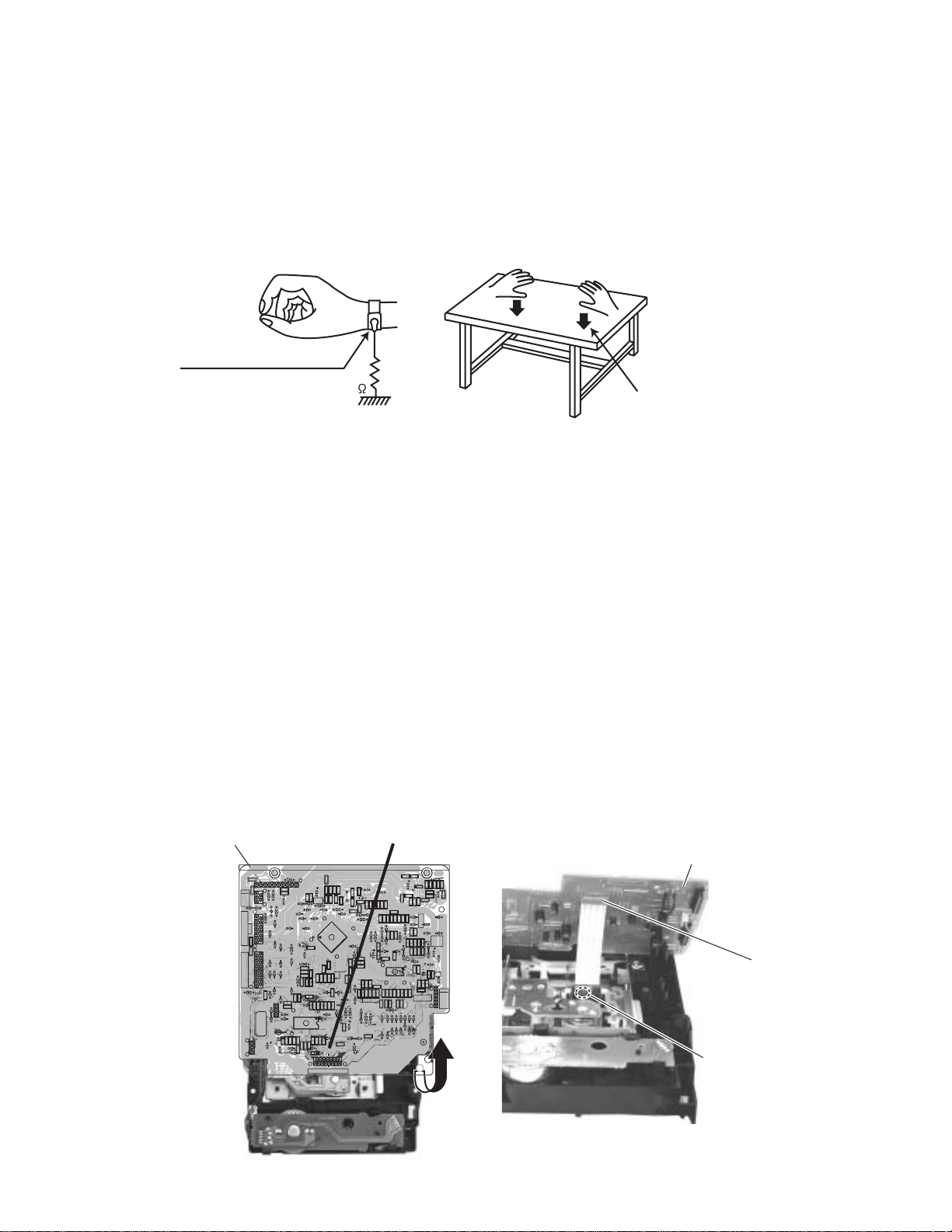
1.6 Preventing static electricity
C
rt
1
Electrostatic discharge (ESD), which occurs when static electricity stored in the body, fabric, etc. is discharged, can destroy the laser
diode in the traverse unit (optical pickup). Take care to prevent this when performing repairs.
1.6.1 Grounding to p revent damage by static electricity
Static electricity in the work area can destroy the optical pickup (laser diode) in devices such as CD players.
Be careful to use proper grounding in the area where repairs are being performed.
(1) Ground the workbench
Ground the workbench by laying conductive material (such as a conducti ve sheet) or an iron plate over it before placing the
traverse unit (optical pickup) on it.
(2) Ground yourself
Use an anti-static wrist strap to release any static electricity built up in your body.
(caption)
Anti-static wrist strap
1M
Conductive material
(conductive sheet) or iron palate
(3) Handling the optical pickup
• In order to maintain quality during tran sport and before installatio n, both sides of the laser diod e on the replacement o ptical
pickup are shorted. After replacement, return the shorted parts to their original condition.
(Refer to the text.)
• Do not use a tester to check the condition of the laser diode in the optical pickup. The tester's internal power source can easily
destroy the laser diode.
1.7 Handling the traverse unit (optical pickup)
(1) Do not subject the traverse unit (optical pickup) to strong shocks, as it is a sensitive, complex unit.
(2) Cut off the shorted part of the flexible cable using nippers, etc. after replacing the optical pickup. For specific details, refer to the
replacement procedure in the text. Remove the anti-static pin when replacing the traverse unit. Be careful not to take too long
a time when attaching it to the connector.
(3) Handle the flexible cable carefully as it may break when subjected to strong force.
(4) I t is not possible to adjust the semi-fixed resistor that adjusts the laser power. Do not turn it.
1.8 Attention when traverse unit is decomposed *Please refer to "Disassembly method" in the text for the CD pickup unit.
• Apply solder to the short land sections before the flexible wire is disconnecte d from the connecto r CN101 on the CD servo board.
(If the flexible wire is disconnected without applying solder, the CD pickup may be destroyed by static electricity.)
• In the assembly, be sure to remove solder from the short land sections after connecting the flexible wire.
D SERVO board
CN601
CD SERVO board
R708
B618
D831
1
B601
R691
R701
R705
B617
CN606
LMCLSW
GND
OPSW
LM+
M.GND
SW10
SW10
CLOSE
OPEN
OPSW
CLSE
CD+B
CN652
CD+B
CDL
A.GND
A.GND
CDR
MUTE
FLAG
SCD
B602
SCD
CDDG
CDDG
BLKCK
/REST
MLD
MDATA
MCLK
CDDG
SUBQ
SQCK
/RST
1
STAT
W605
31
IC802
C832
51
C833
R831
C831
13
L831
C658
116
C657
C672
C671
CN651
C670
B612
R805
R806
C824
Q801
BE
R654
R821
12
13
C801
C811
R813
R801
R802
C823
C816
R636
C814
B607
B606
B605
X651
R692
C677
R666
C673
C656
R695
R696
R665
C651
61
1
C655
21
R653
C654
R651
R652
R655
R656
R658
C653
R601
R602
B611
R657
R659
C813
R807
R808
R809
R822
R824
R823
C812
1
IC801
C821
24
C802
R803
R804
R812
B608
C815
115
CN601
F-T-T+F+GNDVRLDMDT2KF1NCT1SRF2
C652
R667
R681
41
C676
R682
C822
R710
R706
C691
R703
R670
C669
C679
D601
C665
R669
R664
C667
C668
C680
B614
R684
C681
R685
R663
C664
C663
R662
R648
C615
C616
R607
B613
C612
C614
C610
C617
R683
C607
C643
C641
C642
R642
IC601
171632
B619
R620
R603
R604
C605
C606
R641
R643
R619
B610
C601
B609
B603
C695
C699
R709
C693
IC652
B604
C696
C694
R707
R702
R704
C692
R668
R661
C661
A.GND
ARF
B615
C621
R617
C613
C620
C622
R647
R612
R613
C611
C619
C631
1
C624
C623
BE
B616
C632
Q631
C
D602
R632
R631
R634
R635
1
CN801
C633
FMD.GND
SM+
R605
R606
R610
R611
R621
C602
C603
C604
SMREST
6
FM+
R618
CN60
T02
Soldering pa
(No.MB049)1-5
Page 6
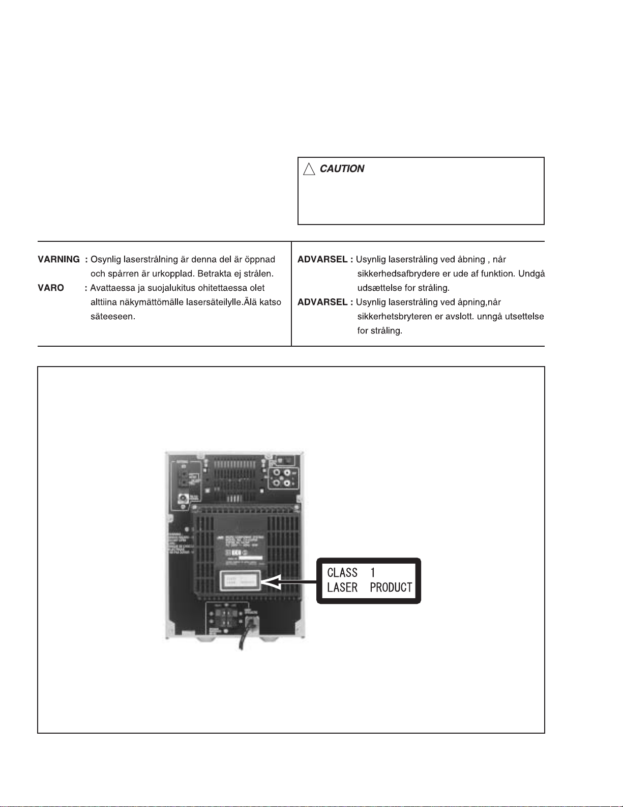
1.9 Important for laser products
1.CLASS 1 LASER PRODUCT
2.DANGER : Invisible laser radiation when open and inter
lock failed or defeated. Avoid direct exposure to beam.
3.CAUTION : There are no serviceable parts inside the
Laser Unit. Do not disassemble the Laser Unit. Replace
the complete Laser Unit if it malfunctions.
4.CAUTION : The compact disc player uses invisible laser
radiation and is equipped with safety switches which
prevent emission of radiation when the drawer is open and
the safety interlocks have failed or are de
feated. It is dangerous to defeat the safety switches.
5.CAUTION : If safety switches malfunction, the laser is able
to function.
6.CAUTION : Use of controls, adjustments or performance of
procedures other than those specified herein may result in
hazardous radiation exposure.
!
Please use enough caution not to
see the beam directly or touch it
in case of an adjustment or operation
check.
REPRODUCTION AND POSITION OF LABEL and PRINT
WARNING LABEL
1-6 (No.MB049)
Page 7

SECTION 2
SPECIFIC SERVICE INSTRUCTIONS
This service manual does not describe SPECIFIC SERVICE INSTRUCTIONS.
(No.MB049)1-7
Page 8
SECTION 3
A
A
DISASSEMBLY
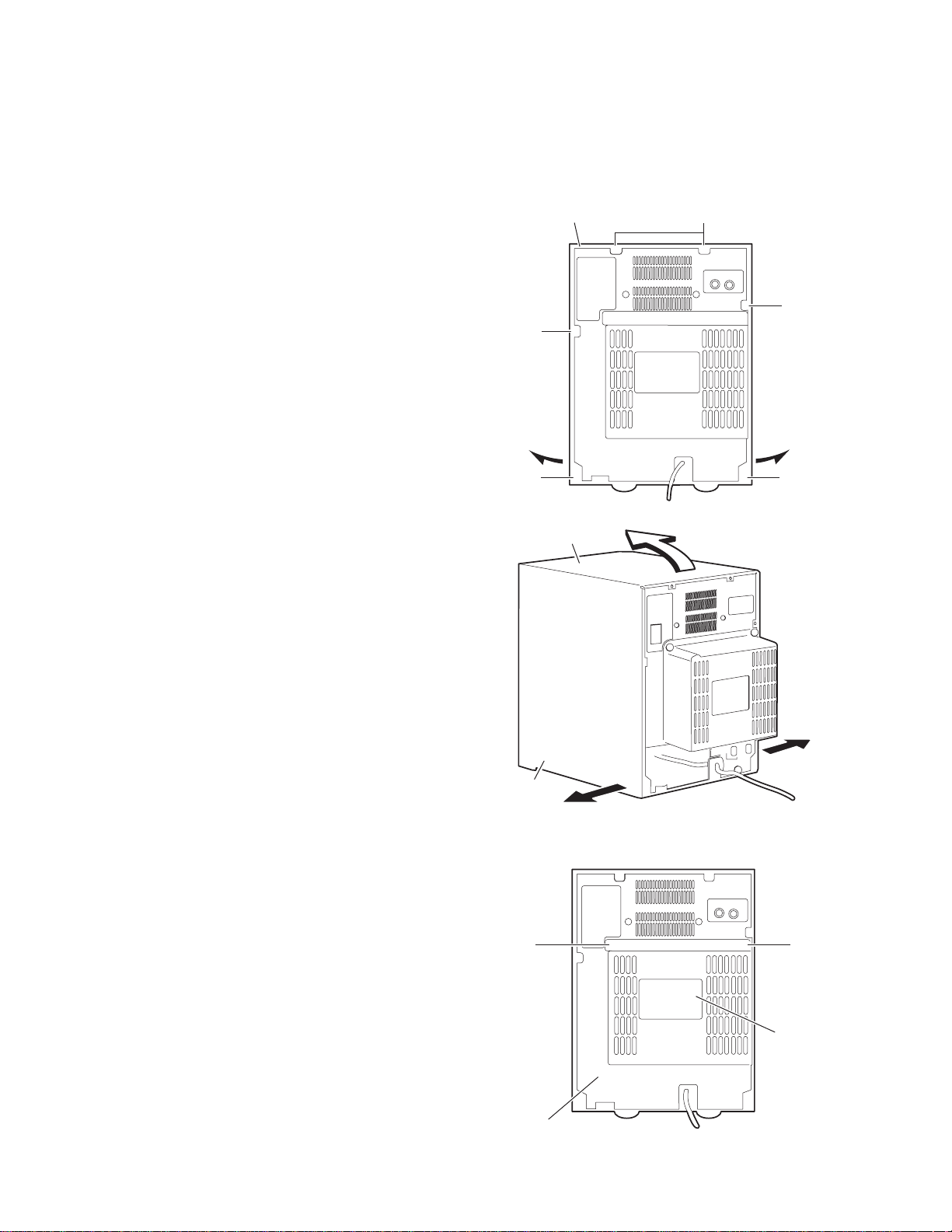
3.1 Main body
3.1.1 Removing the metal cover
(See Fig.1 and 2)
(1) Remove the six screws A on the back of the body.
(2) Remove the two screws B on the side of the body.
(3) Pull both sides of the me tal cover outward and lift the re ar
part of the cover.
Metal cover
A
3.1.2 Removing the rear cover
(See Fig.3)
• Prior to performing the fo llowing proce dure, remove the metal
cover.
(1) Remove the two screws C on the back of the body.
A
Metal cover
B
x2
A
Fig.1
Fig.2
1-8 (No.MB049)
C
Rear panel
C
Rear cover
Fig.3
Page 9
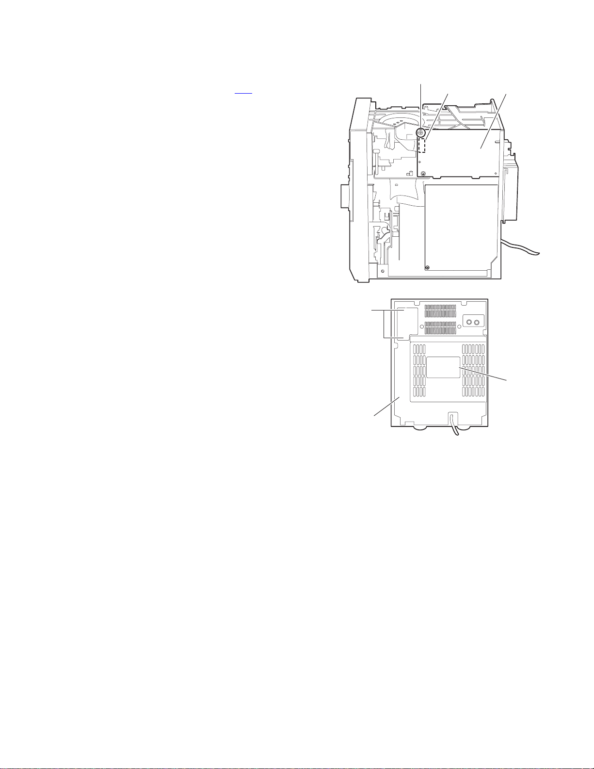
3.1.3 Removing the tuner board
(See Fig.4 and 5)
• Prior to performing the following procedure, remove the metal
cover.
(1) Disconnect the card wire from connector CN1
board.
(2) Remove the screw D on the right side of the body.
(3) Remove the two screws E on the rear panel.
on the tuner
E
D
CN1
Fig.4
Tuner board
Rear panel
Rear cover
Fig.5
(No.MB049)1-9
Page 10

3.1.4 Removing the CD mechanism assembly
(See Fig.6 to 8)
• Prior to performing the fo llowing proce dure, remove the metal
cover and the rear cover.
(1) Disconnect the card wires from connecto r CN903, CN904
on the main board on the upper side of the body.
(2) Remove the screw D attaching the tuner board and the CD
mechanism on the right side of the body.
(3) Remove the two screws F attaching the rear panel and the
CD mechanism on the back of the body.
(4) Move the rear part of the CD mechanism assembly
upwards to disengage the two joints a and release from the
rear panel. Pull the front panel toward the front and move
the rear part of the CD mechanism assembly upwards.
Then pull out the CD mechanism assembly from the front
panel backward.
REFERENCE:
To remove the CD mechanism assembly efficiently,
disconnect the card wireconnecting the tuner board with the
main board in advance.
Main board
CN904
CN903
Rear panel
Tuner board
Card wires
Front panel assembly
CD mechanism assembly
Front panel assembly
Joint a
CD mechanism assembly
Fig.6
D
Tuner board
Fig.7
F
Joint a
1-10 (No.MB049)
G
Rear panel
G
G
Fig.8
Page 11

3.1.5 Remove the rear panel
(See Fig.8 to 10)
• Prior to performing the following procedure, remove the metal
cover, rear cover and the CD mechanism assembly.
(1) Remove the five screws G attaching the rear panel.
(2) Disconnect the card wire from CN902
on the main board.
(3) Disengage the lower two jo ints b on each side of the rear
panel using a screwdriver and remove the rear panel
backward (The tuner board and the fan will be also
detached.Remove them as needed).
Rear panel
Joint b
Fig.9
Joint b
Rear panel
Fig.10
(No.MB049)1-11
Page 12

3.1.6 Removing the main board / heat sink
(See Fig.11 to 13)
• Prior to performing the fo llowing proce dure, remove the metal
cover, the rear cover, the CD mechanism assembly and the
rear panel.
(1) Disconnect the card wire from connector CN900
and CN931 on the main board.
(2) Disconnect the wire from CN906 and CN907 respectively.
(3) Remove the two screws H attaching the main board to the
chassis on the left side ofthe body and disengage the two
joints c.
(4) Remove the two screws J attaching the heat sink to the
main board.
, CN901
Main board
CN931
CN901
CN900
Main board
CN906
CN907
Fig.11
Front panel assembly
1-12 (No.MB049)
HH
Joint c
Fig.12
Main board
Heat sink
J
Fig.13
Page 13

3.1.7 Removing the power transformer assembly
r
(See Fig.14 and 15)
• Prior to performing the following procedure, remove the metal
cover, the rear cover, the CD mechanism assembly and the
rear panel.
(1) Remove the cord stopper upwards on the back of the body.
(2) Disconnect the power cord from connector J1000
board of the power transformer assembly.
(3) Disconnect the wire from connector FW903
board.
(4) Remove the four screws K attaching the power transformer
assembly.
on the
on the main
J1000
Power transformer
assembly
Main board
CN907
Cord stopper
Power cord
Fig.14
K
J1000
Power transforme
assembly
K
Fig.15
(No.MB049)1-13
Page 14

3.1.8 Removing the front panel assembly
(See Fig.11, 16 and 17)
• Prior to performing the fo llowing proce dure, remove the metal
cover, the rear cover, the CD mechanism assembly and the
rear panel.
(1) Disconnect the card wire from connector CN900
and CN931 on the main board (Refer to Fig.11).
(2) Disconnect the wire from connector CN906 and FW903 on
the main board (Refer to Fig.11).
(3) Remove the two screws L on each lower side of the body.
(4) Release the lower joints d on each side of the body using
a screwdriver. Pull out thefront panel assembly toward the
front.
, CN901
Front panel assembly
Main board
Joint d
L
Fig.16
Front panel assembly
Joint d
CN931
L
Fig.17
Main board
Power transformer
assembly
1-14 (No.MB049)
Page 15

3.1.9 Removing the display board / switch board
(See Fig.18 to 20)
• Prior to performing the following proce dure, remove the front
panel assembly.
(1) Pull out the VOLUME knob on the front panel.
(2) Remove the six screws M attaching the switch board.
Then, open the switch board in the direction of arrow, and
remove the operation button.
(3) Remove the ten screws N attaching the Display board and
the two screws P of the LCD holder.
Display board
N
N
Front panel assembly
VOLUME knob
Fig.18
MM
Switch board
N
P
Fig.20
Switch board
Fig.19
(No.MB049)1-15
Page 16

3.1.10 Removing the cassette mechanism assembly
(See Fig.21 and 22)
• Prior to performing the following procedure, remo ve the front
panel assembly.
(1) Press the EJCT button on the front panel to open the
cassette door.
(2) Remove the four screws R on the back of the front panel.
3.1.11 Removing the headphone board
(See Fig.21)
• Prior to performing the following procedure, remo ve the front
panel assembly.
(1) Remove the screw Q on the back of the front panel.
Display board
Switch board
R
R
Q
R
Cassette mechanism assembly
Headphone board
Fig.21
Front panel assembly
Cassette door
EJCT button
Fig.22
1-16 (No.MB049)
Page 17

3.2 Cassette mechanism assembly
3.2.1 Removing the Play/Record & Clear head
(See Fig.1~3)
(1) While moving the trigger arm on the right side of the he ad
mount in the direction of the arrow, turn the flywheel R
counterclockwise until the head mount comes ahead and
clicks.
(2) The head turn s counterclockwise as you turn the flywheel
R counterclockwise (See Fig.2 and 3).
(3) Disconnect the flexible wire from connector CN31
head amplifier & mechanism control board.
(4) Remove the spring from the back of the head.
(5) Loosen the azimuth screw for reversing attaching the head.
(6) Remove the head on the front sid e of the hea d mount.
on the
Cassette mechanism assembly
Fig.1
Head
Fly wheelR
Trigger armHead mount
Flexible wire
Fly wheel R
Fig.2
Azimuth screw
Head
for reversing
Spring
CN31
Head amplifer & mecha control board
Fig.3
(No.MB049)1-17
Page 18

3.2.2 Removing the head amplifier & mechanism con t rol board
(See Fig.4)
(1) Turn over the cassette mech anism assembly and remove
the three screws A attaching the head amplifier & mechanism control board.
(2) Disconnect the flexible wire fro m connector CN31
head amplifier & mechanism control board.
(3) Disconnect connector CN32
anism control board from connector CN1
board.REFERENCE: If necessary, unsolder the 4-pin wire
soldered to the main motor.
3.2.3 Removing the main motor
(See Fig.4~7)
(1) Remove the two screws B .
(2) Half raise the motor and remove the capstan belt from the
motor pulley.
ATTENTION:
Be careful to keep the capstan belt from grease. When reassembling, refer to Fig.6 and 7 for attaching the capstan belt.
Head amplifier & mecha control board
of the head amplifier & mech-
on the reel pulse
on the
Main motor assembly
Capstan belt
Fig.5
Main motor assembly
CN31
Flexible wire
A
AA
Fig.4
CN32
4pin wire
B
Main motor assembly
Motor pulley
Capstan belt
Fig.6
Main motor assembly
Fly wheel
1-18 (No.MB049)
Capstan belt
Motor pulley
Fig.7
Page 19

3.2.4 Removing the flywheel
(See Fig.8, 9)
• Prior to performing the following procedure, remove the he ad
amplifier & mechanism control board and the main motor assembly.
(1) From the front side of the cassette mechanism, remove the
slit washers attaching the capstan shaft L and R. Pull out
the flywheels backward.
Fly wheel R Fly wheel L
Fig.8
Fly wheel R
Capstan shaft R Capstan shaft L
Slit washer
Fig.9
3.2.5 Removing the reel pulse board and solenoid
(See Fig.10)
• Prior to performing the following procedure, remove the head amplifier & mechanism control board.
(1) Remove the screw C.
(2) Release the tab a, b, c, d and e retaining the reel pulse board.
(3) Release the tab f and g attaching the solenoid on the reel pulse board.
(4) The reel pulse board and the solenoid come off.
Fly wheel L
bc
a
Solenoid
g
f
d
Reel pulse board
C
e
Fig.10
(No.MB049)1-19
Page 20

3.2.6 Reattaching the Play/ Record & Clear head
r
r
(See Fig.11~13)
(1) Reattaching the head mount assembly.
a) Change front of the direction cover of the head
mount assembly to the left (Turn the head forward).
b) Fit the bosses O', P', Q', U' and V' on the head mount
assembly to the holes P and V, the slots O, U and Q
of the mechanism sub assembly (See Fig.11 to 13).
CAUTION:
To remove the head mount assembly, turn the direction
cover to the left to disengage the gear. If the gear can not
be disengaged easily, push up the boss Q' slightly and
raise the rear side of the head mounts slightly to return
the direction lever to the reversing side.
(2) Tighten the azimuth screw for reversing.
(3) Reattach the spring from the back of the Play/ Record &
Clear head.
(4) Connect the flexible wire to connector CN31
amplifier & mechanism control board.
on the head
U' Q'
Head mount assembly
Head mount assembly
O'
Fig.11
P'
P'
V'
V'
Direction cove
Spring
Flexible wire
V
O
P
Q
Head
Direction cove
U
Fig.12
Azimuth screw for reversing
Head mount
1-20 (No.MB049)
CN31
Fig.13
Head amplifier &
mechanism control board
Page 21

SECTION 4
ADJUSTMENT
4.1 Measurement Instruments Required for Adjustment
(1) Low frequency oscillator
This oscillator should have a capacity to output 0dBs to
600Ω at an oscillation frequency of 50Hz-20kHz.
(2) Attenuator impedance : 600Ω
(3) Electronic voltmeter
(4) Distortion meter
(5) Frequency counter
(6) Wow & flutter meter
(7) Test tape
VT703L : Head azimuth
VT712 : Tape speed and running unevenness (3kHz)
VT724 : Reference level (1kHz)
(8) Blank tape
TYPE l : AC-225
TYPE ll : AC-514
(9) Torque gauge : For play and back tension
FWD(TW2111A), REV(TW2121a) and FF/REW(TW2231A)
(10) Test disc: CTS-1000
4.2 Measurement conditons
Power supply voltage : AC230V (50Hz)----B/E/EE/EN
: AC110/127V/230V(50/60Hz)
: UB/UF/US/UX/U
Reference output Speaker : 0.775V/4Ω
Headphone : 0.077V/32Ω
Reference frequency and
input level
Input for confirming recording
and playback characteristics
Measurement output terminal at Speaker J3002
Load resistance 4Ω
4.2.1 Radio Input signal
AM frequency 400Hz
AM modulation 30%
FM frequency 400Hz
FM frequency deviation 22.5kHz
MIX MIC:-54dBs
(UB/UF/US/UX/U)
1kHz, AUX : -8dBs
AUX : -28dBs
4.2.2 Tuner section
B/E/EN version
FM Band cover : 87.5~108MHz
MW Band cover : 522~1,629kHz
LW Band cover : 144~288kHz
EE version
FM Band cover : 65~74MHz, 87.5~108MHz
MW Band cover : 522~1,629kHz
LW Band cover : 144~288kHz
UB/UF/US/UX/U version
FM Band cover : 87.5~108MHz
MW Band cover : 531~1,602kHz, 530~1,710kHz
SW Band cover : SW1 2.3~6.995MHz
: SW2 7~21.85MHz
Voltage applied to tuner +B : DC5.7V
VT : DC 12V
Reference measurement output 26.1mV(0.28V)/3Ω
Input positions AM : Standard loop antenna
FM : TP1 (hot) and TP2 (GND)
4.2.3 Standard measurement position of volume
Function switch to Tape
Beat cut switch to Cut
Super Bass/Active hyper Bass to OFF
Bass Treble to Center
Adjustment of main volume to reference output VOL : 28V
Precautions for measurement
(1) Apply 30pF and 33kΩ to the IF sweeper output side and
0.082µ F and 100kΩ in series to the sweeper input side.
(2) The IF sweeper output level should be made as low as
possible within the adjustable range.
(3) Since the IF sweeper is a fixe d device, there is no need
to adjust this sweeper.
(4) Since a ceramic oscillator is used, ther e is no need to
perform any MIX adjustment.
(5) Since a fixed coil is used, there i s no need to adjust the
FM tracking.
(6) The input and output earth systems are separated. In
case of simultaneously measuring the voltage in both of
the input and output systems with an electronic voltmeter
for two channels, therefore, the earth should be connected particularly carefully.
(7) In the case of BTL connection amp., the minus terminal
of speaker is not for earthing. Therefore, be sure not to
connect any other earth terminal to this terminal. This
system is of an BTL system.
(8) For connecting a dummy resisto r when measuring the
output, use the wire with a greater code size.
(9) Whenever any mixed tape is used, use the band pass fil-
ter (DV-12).
(No.MB049)1-21
Page 22

4.3 Cassette mechanism adjustment
Head azinuth
adjustment screw
(Forward side)
Mecha control board
MOTOR SPEED
VR37
BIAS ADJ
VR31
Head azinuth
adjustment screw
(Reverse side)
RECRAGRECL
SW8V
VR37
C308
R313
R315
R314
C310
C313
B155
R327
C221
Q302
C319
C314
C317
C121
B112
L303
C316
L301
VR31
Head azinuth
adjustment screw
(Forward side)
Head azinuth
adjustment screw
(Reverse side)
CN31
R/P head, Erase head
B102
B101
NC
9
C201
B109B108
C209
CN33
R342
C213
R210
R209
C207
B159
16
R341
C208
R207
B200
1
B110
CN31
1
R205
R208
B160
R340
R105
C105
R343
C305
C206
R345
R201
1IC31
MB
PBRAGPBL
MS
MG
1
CN34
B198
R353
Q305
R310
R335
C106
Q103
R305
C307
R303
R122
C103
B163
Q321
Q101
R221
10
B156
C303
R115
B157
R108
R101
C113
R110
R109
R102
C110
C104
R301
R121
1
C108
C107
9
B151
R112
R111
C102
R107
B152
C302
R103
1
C301
C111
B164
C306
R304
C109
B158
8
B106
C101
6
B166
R116
R212
R211
C211
R216
9
IC32
TAP
C304
B113
C202
C210
Q331
RRE
C375
C205
R215
C203
B161
R339
C334
R106
R206
5VMGSOL
R204
R203
B153
R104
R222
C204
B168
PHO
R202
C333
R375
Q201
C332
PLA
Q203
C331
FRE
Q372
R331
B167
R371
10
CN32
B162
R372
R373
C371
Q375
R376
C374
R338
C376
B
E
D375
Q376
B
Q371
E
R337
R336
9
IC33
8
70u
16
1
1-22 (No.MB049)
Page 23

4.3.1 Mechanism section
Item Condition Measurement method Ref. value
Head azimuth Test tape
:VT703L (8kHz)
Output terminal
:Speaker out
Tape speed Test tap
:VT712 (3kHz)
Output terminal
:Speaker out or Headphone out
Item Condition Measurement method Ref. value
Tape speed
diviation at FWD/
REV
Wow & Flutter Test tape
Test tape
: VT712 (3kHz)
Output terminal
:Speaker out or Headphone out
: VT712 (3kHz)
Output terminal
:Speaker out or Headphone out
(1) Playback the test tape VT703L (8kHz).
(2) Adjust to maximu m output level by azi-
muth adjustment screw for forward side
and reverse side.
(3) This adjustment is adjust by adjustment
screw of forward side and adjustment
screw of reverse side.
Playback the test tape VT712 (3kHz) at end of
forward side,adjust to 2,940~3,90Hz indication
of frequency counter by VR37.
Playback the test tape VT712 (3kHz) at end of
forward and reverse, tape speed deviation
should be less than 6.0Hz.
Playback the test tape VT712 (3kHz) at start of
forward and reverse, Wow & Flutter are should
be less than 0.25%(WRMS).
Adjustment
position
Maximum output Only adjust
at changed
head
2,940 ~ 3,090Hz VR37
Adjustment
position
Leass than
6.0Hz
Less than 0.25%
(WRMS)
VR31
(No.MB049)1-23
Page 24

4.3.2 Electrical adjustment
Item Condition Measurement method Ref. value
Recording BIAS
adjustment
R/P playback
frequency
response
4.3.3 Electrical response confirmation
Item Condition Measurement method Ref. value
Recording bias
current
Erase current (reference value)
• Forward or Reverse
• Test tape
: AC-514 TYPE ll
: AC-225 TYPE l
• Output termina
Recording head
• Reference frequency
: 1kHz / 10kHz
(Reference: -20dB)
• Test tape
: AC-514 TYPE ll
• Input terminal
: OSC IN
• Forward or Reverse
• Test tape
: TYPE ll (AC-514)
• Measurement terminal
: BIAS test point on printed
circuit board
• Forward or Reverse
• Rec condition
Test tape
: AC-514 TYPE ll
: AC-225 TYPE l
• Measurement terminal
Both side of Erase head
(1) Set the test tape(AC-514 TYPE ll and
AC-225 TYPE l), then make REC/
PAUSE condition.
(2) Connect 100Ω to recording head by se-
ries, then connect to VTVM for measurement the current.
(3) After setting, start the recording by re-
lease the PAUSE, in this time bias current adjust to next fig. by VR31
and VR32
4.0 µA (TYPE ll) and 4.20 µA (TYPE l).
(1) Set the test tape (AC-514 TYPE ), then
make REC/PAUSE condition.
(2) Release the PAUSE, then start recording
the 1kHz and 10kHz of reference frequency from oscillator.
(3) Playback the recorded position, 1kHz
and 10kHz output deviation should -1dB
2dB to readjust by VR31
VR32 for Rch.
(1) Change BIAS1 and 2, confirm the fre-
quency should be change.
(2) Set the test tape (AC-514 TYPE ll), then
make REC/PAUSE condition.
(3) Confirm the frequency should 100Hz ±
6kHz at BIAS test point on printed circuit
board.
(1) Set the test tape (AC-514 TYPE ll and
AC-225 TYPE l), then make REC/
PAUSE condition.
(2) Release the PAUSE to REC condition,
connect 1W to ERASE head by series,
then confirm the erase current at both
side of erase head.
for Rch.
for Lch
for Lch and
AC-225
: 4.20µA
AC-514
: 4.0µA
Output deviation
1kHz/10kHz
: -1dB ± 2dB
100 kHz ± 6 kHz
TYPE ll
: 120 mA
TYPE l
: 75 mA
Adjustment
position
VR31
VR31
Adjustment
position
1-24 (No.MB049)
Page 25

TROUBLESHOOTING
5.1 Flow of functional operation untill TOC read (CD)
Power ON
Power Key
SECTION 5
Slider turns REST
SW ON.
Automatic tuning
of TE offset
Check Point
Check that the voltage at the pin 5
of CN801 is 0V?
VREF
Tracking error waveform at TOC reading
pin 20 of
IC601(TE)
Approx
1.7V
Tracking
servo
Disc start
to rotate
off
Automatic measurement
of TE amplitude and
automatic tuning of
TE balance
Approx.1sec
Tracking
servo ON
Disc to be
braked to stop
TOC reading
finishes
500mv/div
2ms/div
Fig.1
Laser ON
Detection of disc
Automatic tuning of
Focus offset
Automatic measurement of
Focus S-curve amplitude
Disc is rotated
Focus servo ON
(Tracking servo ON)
Automatic measurement of
Tracking error amplitude
Automatic tuning of
Tracking error balance
Check that the voltage at the
pin2 of IC601 is 4.4V?
Confirm that the Focus error
S-cuve, ie at the pin23 of
IC601 is approx.2Vp-p
Confirm that the siganl from
pin 5,6 of IC801 is a 2V
accelerated pulse with approx.
700ms.
Confirm the waveform of
the Tracking error signal
at the pin20 of IC601
(See fig-1)
Automatic tuning of
Focus error balance
Automatic tuning of
Focus error gain
Automatic tuning of
Tracking error gain
TOC reading
Play a disc
Confirm the eye-pattern
at the lead of TP1
(No.MB049)1-25
Page 26

5.2 Maintenance of laser pickup (CD)
(1) Cleaning the pick up lens
Before you replace the pick up, please try to clean the lens
with a alcohol soaked cotton swab.
(2) Life of the laser diode
When the life of the laser diode has expired, the following
symptoms will appear.
• The level of RF output (EFM output : ampli tude of eye
pattern) will below.
5.3 Replacement of laser pickup (CD)
Turn off the power switch and, disconnect the
power cord from the ac outlet.
Replace the pickup with a normal one.(Refer
to "Pickup Removal" on the previous page)
Is the level of
RFOUT under
1.1V 0.15Vp-p?
NO
Replace it.
YES
O.K
(3) Semi-fixed resistor on the APC PC board
The semi-fixed resistor on the APC printed circuit board
which is attached to the pickup is used to adjust the laser
power. Since this adjustment should be performed to
match the characteristics of the whole optical block, do not
touch the semi-fixed resistor.
If the laser power is lower than the specified value, the laser diode is almost worn out, and the laser pickup should
be replaced.
If the semi-fixed resistor is adjusted while the pickup is
functioning normally, the laser pickup may be damaged
due to excessive current.
Plug the power cord in, and turn the power on.
At this time, check that the laser emits for
about 3seconds and the objective lens moves
up and down.
Note: Do not observe the laser beam directly.
Play a disc.
Check the eye-pattern at TP1.
Finish.
1-26 (No.MB049)
Page 27

(No.MB049)1-27
Page 28

VICTOR COMPANY OF JAPAN, LIMITED
AV & MULTIMEDIA COMPANY AUDIO/VIDEO SYSTEMS CATEGORY 10-1,1chome,Ohwatari-machi,Maebashi-city,371-8543,Japan
(No.MB049)
Printed in Japan
WPC
 Loading...