

Page 1
SERVICE MANUAL
MICRO COMPONENT SYSTEM
MB57320069
UX-NB7DABB,UX-NB7DABE,
UX-NB7DABEN
CA-UXNB7DAB SP-UXNB7DABSP-UXNB7DAB
Lead free solder used in the board (material : Sn-Ag-Cu, melting point : 219 Centigrade)
TABLE OF CONTENTS
1 PRECAUTION. . . . . . . . . . . . . . . . . . . . . . . . . . . . . . . . . . . . . . . . . . . . . . . . . . . . . . . . . . . . . . . . . . . . . . . . . 1-3
2 SPECIFIC SERVICE INSTRUCTIONS . . . . . . . . . . . . . . . . . . . . . . . . . . . . . . . . . . . . . . . . . . . . . . . . . . . . . . 1-7
3 DISASSEMBLY . . . . . . . . . . . . . . . . . . . . . . . . . . . . . . . . . . . . . . . . . . . . . . . . . . . . . . . . . . . . . . . . . . . . . . . 1-7
4 ADJUSTMENT . . . . . . . . . . . . . . . . . . . . . . . . . . . . . . . . . . . . . . . . . . . . . . . . . . . . . . . . . . . . . . . . . . . . . . . . 1-7
5 TROUBLESHOOTING . . . . . . . . . . . . . . . . . . . . . . . . . . . . . . . . . . . . . . . . . . . . . . . . . . . . . . . . . . . . . . . . . . 1-7
COPYRIGHT © 2006 Victor Company of Japan, Limited
No.MB573
2006/9
Page 2
SPECIFICATION
Amplifier section OUTPUT POWER 10 W (5 W + 5 W) at 4 Ω (10% THD)
Speakers/Impedance 4 Ω - 16 Ω
Audio Input LINE IN 500 mV/47 kΩ (at "LINE IN LVL1")
250 mV/47 kΩ (at "LINE IN LVL2")
125 mV/47 kΩ (at "LINE IN LVL3")
Audio Output LINE OUT 1.0 Vrms (47 kΩ) (at "LINE OUT LVL1")
2.0 Vrms (47 kΩ) (at "LINE OUT LVL2")
Tuner section FM Tuning range 87.50 MHz - 108.00 MHz
AM (MW) Tuning range 522 kHz - 1 629 kHz
DAB tuning range BAND III 174.928 MHz - 239.200 MHz
L-BAND 1 452.960 MHz - 1 490.624 MHz
CD player section Dynamic range 88 dB
Signal-to-noise ratio 93 dB
Wow and flutter Immeasurable
Speakers Speaker units 8 cm cone × 1
Impedance 4 Ω
Dimensions (approx.) 130 mm × 171 mm × 136 mm (W/H/D)
Mass (approx.) 0.75 kg each
General Power requirements AC 230 V , 50 Hz
Power consumption 20.0 W (Power on), 2.5 W (Standby mode)
2.0 W or less (Save mode)
Mass 1.8 kg
Dimensions (W × H × D) 270 mm × 68.5 mm × 203 mm
Specifications and appearance are subject to change without prior notice.
1-2 (No.MB573)
Page 3
SECTION 1
PRECAUTION
1.1 Safety Precautions
(1) This design of this product contains special hardware and
many circuits and components specially for safety purposes. For continued protection, no changes should be made
to the original design unless authorized in writing by the
manufacturer. Replacement parts must be identical to
those used in the original circuits. Services should be performed by qualified personnel only.
(2) Alterations of the design or circuitry of the product should
not be made. Any design alterations of the product should
not be made. Any design alterations or additions will void
the manufacturers warranty and will further relieve the
manufacture of responsibility for personal injury or property
damage resulting therefrom.
(3) Many electrical and mechanical parts in the products have
special safety-related characteristics. These characteristics are often not evident from visual inspection nor can the
protection afforded by them necessarily be obtained by using replacement components rated for higher voltage, wattage, etc. Replacement parts which have these special
safety characteristics are identified in the Parts List of Service Manual. Electrical components having such features
are identified by shading on the schematics and by ( ) on
the Parts List in the Service Manual. The use of a substitute
replacement which does not have the same safety characteristics as the recommended replacement parts shown in
the Parts List of Service Manual may create shock, fire, or
other hazards.
(4) The leads in the products are routed and dressed with ties,
clamps, tubings, barriers and the like to be separated from
live parts, high temperature parts, moving parts and/or
sharp edges for the prevention of electric shock and fire
hazard. When service is required, the original lead routing
and dress should be observed, and it should be confirmed
that they have been returned to normal, after reassembling.
(5) Leakage shock hazard testing
After reassembling the product, always perform an isolation check on the exposed metal parts of the product (antenna terminals, knobs, metal cabinet, screw heads,
headphone jack, control shafts, etc.) to be sure the product
is safe to operate without danger of electrical shock.Do not
use a line isolation transformer during this check.
• Plug the AC line cord directly into the AC outlet. Using a
"Leakage Current Tester", measure the leakage current
from each exposed metal parts of the cabinet, particularly any exposed metal part having a return path to the
chassis, to a known good earth ground. Any leakage current must not exceed 0.5mA AC (r.m.s.).
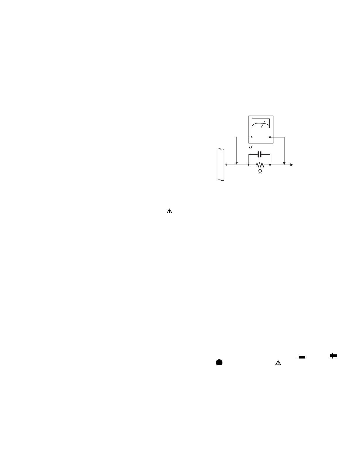
• Alternate check method
Plug the AC line cord directly into the AC outlet. Use an
AC voltmeter having, 1,000Ω per volt or more sensitivity
in the following manner. Connect a 1,500Ω 10W resistor
paralleled by a 0.15µF AC-type capacitor between an ex-
posed metal part and a known good earth ground.
Measure the AC voltage across the resistor with the AC
voltmeter.
Move the resistor connection to each exposed metal
part, particularly any exposed metal part having a return
path to the chassis, and measure the AC voltage across
the resistor. Now, reverse the plug in the AC outlet and
repeat each measurement. Voltage measured any must
not exceed 0.75 V AC (r.m.s.). This corresponds to 0.5
mA AC (r.m.s.).
AC VOLTMETER
(Having 1000
ohms/volts,
or more sensitivity)
0.15 F AC TYPE
Place this
probe on
1500 10W
Good earth ground
1.2 Warning
(1) This equipment has been designed and manufactured to
meet international safety standards.
(2) It is the legal responsibility of the repairer to ensure that
these safety standards are maintained.
(3) Repairs must be made in accordance with the relevant
safety standards.
(4) It is essential that safety critical components are replaced
by approved parts.
(5) If mains voltage selector is provided, check setting for local
voltage.
1.3 Caution
Burrs formed during molding may be left over on some parts
of the chassis.
Therefore, pay attention to such burrs in the case of preforming repair of this system.
1.4 Critical parts for safety
In regard with component parts appearing on the silk-screen
printed side (parts side) of the PWB diagrams, the parts that are
printed over with black such as the resistor ( ), diode ( )
and ICP ( ) or identified by the " " mark nearby are critical
for safety. When replacing them, be sure to use the parts of the
same type and rating as specified by the manufacturer.
(This regulation dose not Except the J and C version)
each exposed
metal part.
(No.MB573)1-3
Page 4
1.5 Safety Precautions (U.K only)
(1) This design of this product contains special hardware and many circuits and components specially for safety purposes. For con-
tinued protection, no changes should be made to the original design unless authorized in writing by the manufacturer. Replacement parts must be identical to those used in the original circuits.
(2) Any unauthorised design alterations or additions will void the manufacturer's guarantee; furthermore the manufacturer cannot
accept responsibility for personal injury or property damage resulting therefrom.
(3) Essential safety critical components are identified by ( ) on the Parts List and by shading on the schematics, and must never
be replaced by parts other than those listed in the manual. Please note however that many electrical and mechanical parts in
the product have special safety related characteristics. These characteristics are often not evident from visual inspection. Parts
other than specified by the manufacturer may not have the same safety characteristics as the recommended replacement parts
shown in the Parts List of the Service Manual and may create shock, fire, or other hazards.
(4) The leads in the products are routed and dressed with ties, clamps, tubings, barriers and the like to be separated from live parts,
high temperature parts, moving parts and/or sharp edges for the prevention of electric shock and fire hazard. When service is
required, the original lead routing and dress should be observed, and it should be confirmed that they have been returned to
normal, after re-assembling.
1.5.1 Warning
(1) Service should be performed by qualified personnel only.
(2) This equipment has been designed and manufactured to meet international safety standards.
(3) It is the legal responsibility of the repairer to ensure that these safety standards are maintained.
(4) Repairs must be made in accordance with the relevant safety standards.
(5) It is essential that safety critical components are replaced by approved parts.
(6) If mains voltage selector is provided, check setting for local voltage.
Burrs formed during molding may be left over on some parts of the chassis. Therefore,
pay attention to such burrs in the case of preforming repair of this system.
1-4 (No.MB573)
Page 5
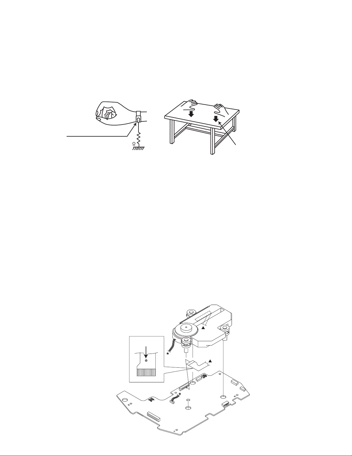
1.6 Preventing static electricity
Electrostatic discharge (ESD), which occurs when static electricity stored in the body, fabric, etc. is discharged, can destroy the laser
diode in the traverse unit (optical pickup). Take care to prevent this when performing repairs.
1.6.1 Grounding to prevent damage by static electricity
Static electricity in the work area can destroy the optical pickup (laser diode) in devices such as laser products.
Be careful to use proper grounding in the area where repairs are being performed.
(1) Ground the workbench
Ground the workbench by laying conductive material (such as a conductive sheet) or an iron plate over it before placing the
traverse unit (optical pickup) on it.
(2) Ground yourself
Use an anti-static wrist strap to release any static electricity built up in your body.
(caption)
Anti-static wrist strap
1M
Conductive material
(conductive sheet) or iron palate
(3) Handling the optical pickup
• In order to maintain quality during transport and before installation, both sides of the laser diode on the replacement optical
pickup are shorted. After replacement, return the shorted parts to their original condition.
(Refer to the text.)
• Do not use a tester to check the condition of the laser diode in the optical pickup. The tester's internal power source can easily
destroy the laser diode.
1.7 Handling the traverse unit (optical pickup)
(1) Do not subject the traverse unit (optical pickup) to strong shocks, as it is a sensitive, complex unit.
(2) Cut off the shorted part of the flexible cable using nippers, etc. after replacing the optical pickup. For specific details, refer to the
replacement procedure in the text. Remove the anti-static pin when replacing the traverse unit. Be careful not to take too long a
time when attaching it to the connector.
(3) Handle the flexible cable carefully as it may break when subjected to strong force.
(4) I t is not possible to adjust the semi-fixed resistor that adjusts the laser power. Do not turn it.
1.8 Attention when traverse unit is decomposed
*Please refer to "Disassembly method" in the text for the pickup unit.
• Apply solder to the short land sections before the card wire is disconnected from the connecto on the servo board. (If the card wire
is disconnected without applying solder, the pickup may be destroyed by static electricity.)
• In the assembly, be sure to remove solder from the short land sections after connecting the card wire.
Short rand
CN601
CN602
(No.MB573)1-5
Page 6
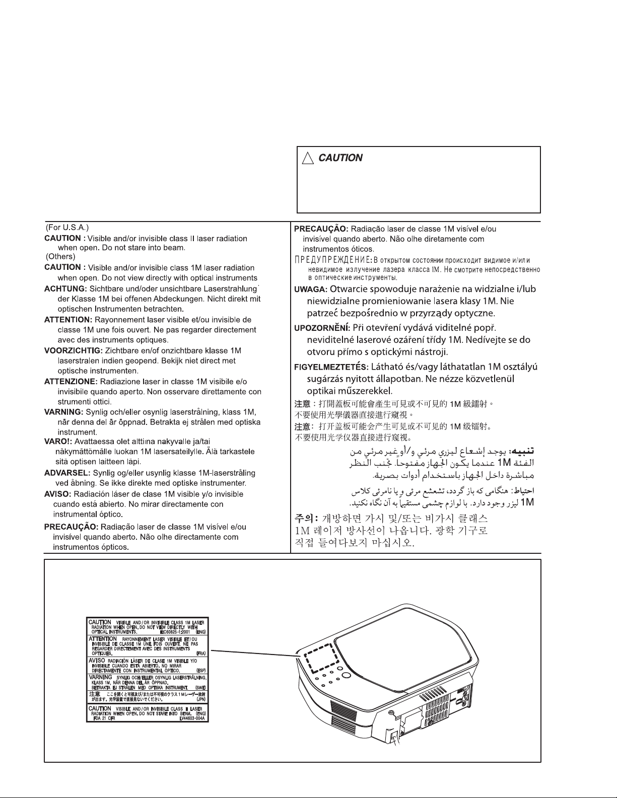
1.9 Important for laser products
1.CLASS 1 LASER PRODUCT
2.CAUTION :
(For U.S.A.) Visible and/or invisible class II laser radiation
when open. Do not stare into beam.
(Others) Visible and/or invisible class 1M laser radiation
when open. Do not view directly with optical instruments.
3.CAUTION : Visible and/or invisible laser radiation when
open and inter lock failed or defeated. Avoid direct
exposure to beam.
4.CAUTION : This laser product uses visible and/or invisible
laser radiation and is equipped with safety switches which
prevent emission of radiation when the drawer is open and
the safety interlocks have failed or are defeated. It is
dangerous to defeat the safety switches.
5.CAUTION : If safety switches malfunction, the laser is able
to function.
6.CAUTION : Use of controls, adjustments or performance of
procedures other than those specified here in may result in
hazardous radiation exposure.
!
Please use enough caution not to
see the beam directly or touch it
in case of an adjustment or operation
check.
REPRODUCTION AND POSITION OF LABELS and PRINT
WARNING LABEL and PRINT
1-6 (No.MB573)
Page 7

SECTION 2
SPECIFIC SERVICE INSTRUCTIONS
Please refer to "UX-N1 (No.MB514)" about this section.
SECTION 3
DISASSEMBLY
Please refer to "UX-N1 (No.MB514)" about this section.
SECTION 4
ADJUSTMENT
Please refer to "UX-N1 (No.MB514)" about this section.
SECTION 5
TROUBLESHOOTING
Please refer to "UX-N1 (No.MB514)" about this section.
(No.MB573)1-7
Page 8

Victor Company of Japan, Limited
Audio/Video Systems Category 10-1,1chome,Ohwatari-machi,Maebashi-city,371-8543,Japan
(No.MB573)
Printed in Japan
VPT
Page 9

SCHEMATIC DIAGRAMS
MICRO COMPONENT SYSTEM
UX-NB7DABB,UX-NB7DABE
UX-NB7DABEN
CD-ROM No.SML200609
Lead free solder used in the board (material : Sn-Ag-Cu, melting point : 219 Centigrade)
Contents
Block diagrams
Standard schematic diagrams
Printed circuit boards
CA-UXNB7DAB SP-UXNB7DABSP-UXNB7DAB
2-1
2-2
2-7 to 9
COPYRIGHT 2006 Victor Company of Japan, Limited.
No.MB573SCH
2006/9
Page 10

In regard with component parts appearing on the silk-screen printed side (parts side) of the PWB diagrams, the
parts that are printed over with black such as the resistor ( ), diode ( ) and ICP ( ) or identified by the " "
mark nearby are critical for safety.
Page 11
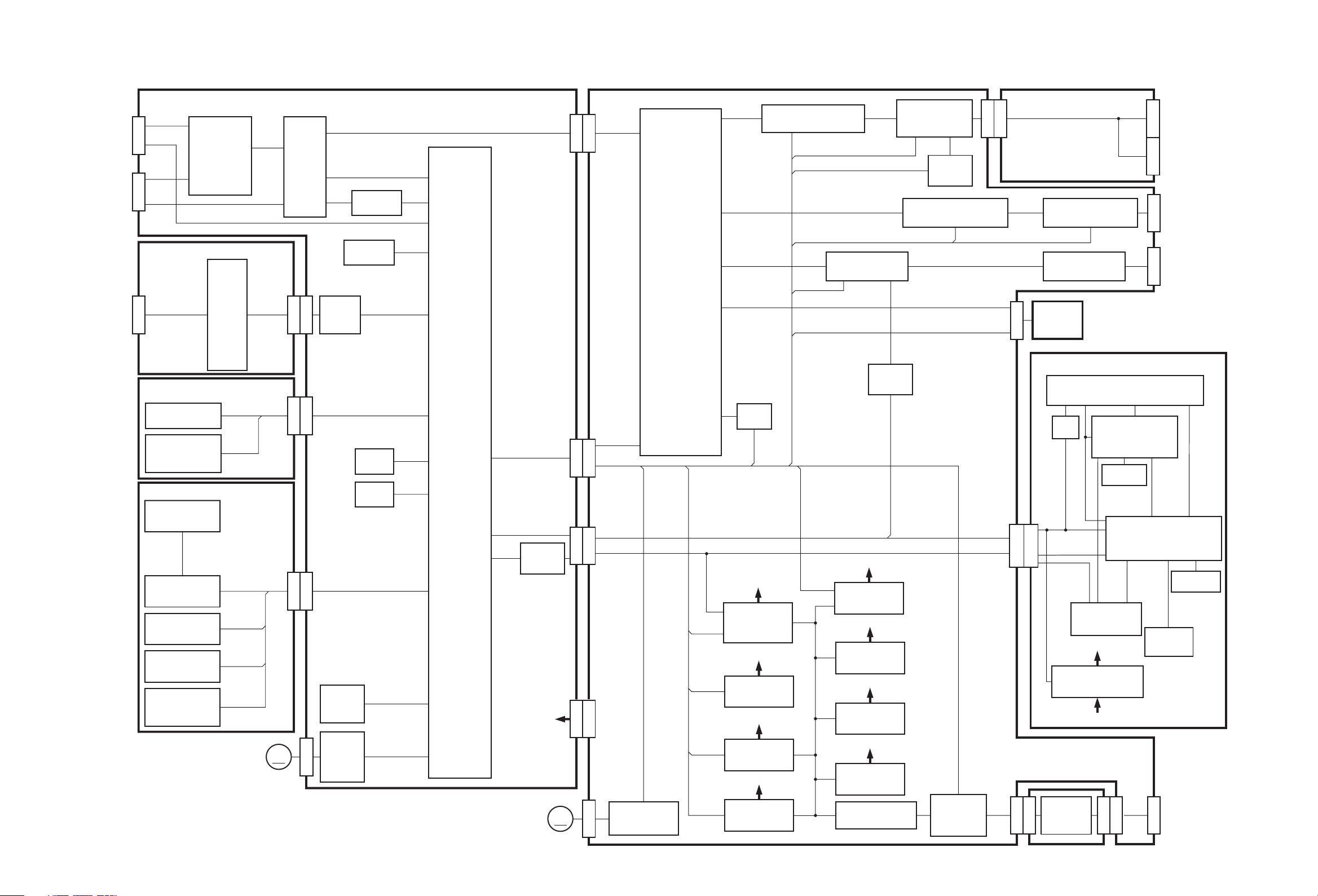
Block diagram
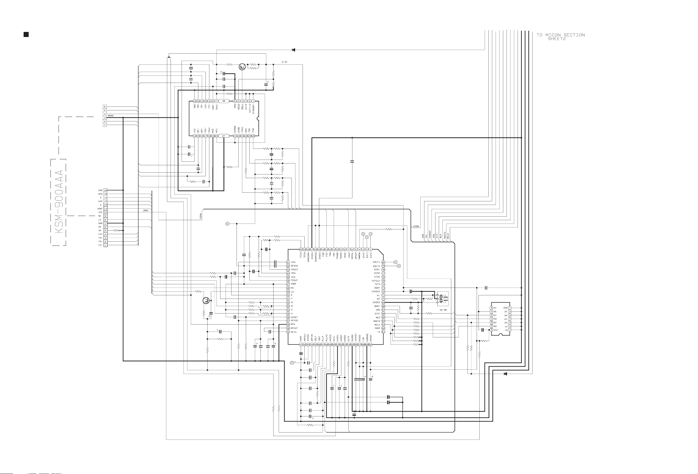
CD traverse
mechanism
CD pickup
mechanism
TOUCH
SENSOR
CD servo control section System control section
SP+/-
CN602
TRV+/-
CDSW
FO+/TR+/-
CN601
IC601
FOCUS
TRACKING
SPINDLE
FEED
BTL. AMP.
TRVP
SPOUT
TRP
FOP
A+C
B+D
E, F
LD, PD
IC602
DSP
CDL/R
MLD
MDATA
MCLK
CDREST
IRQ
STAT
IC604
IRQ
STAT
BUFFER
E2CLK
CD
FM/AM
LINEIN
BUP
E2DATA
REST
BUP
IC701
MICON
L-BAND, FAN2
S.BASS, SMUTE
LMUTE, TUCE
TUCLK, TUDI
TUDO, SW10
FTU, FCD
RDSCLK, RDSDAT
QPLINK, LVOL
VOLDATA, VOLCE
VOLCK, POUT
SAFTY1, SAFTY2
RSW
QPPOWER
DABREST
DABRX
DABON
DABTX
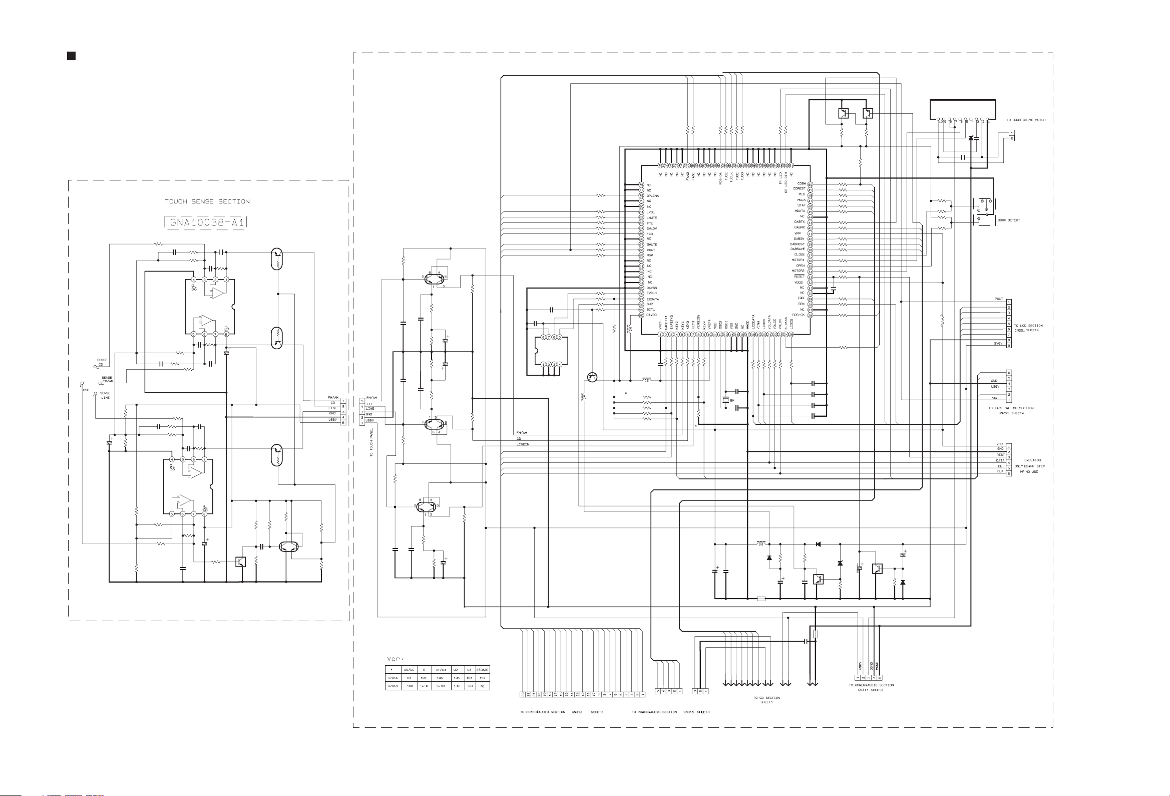
Touch sense section
IC401
OSC
SENSE CD
SENSE FM/AM
SENSE LINE
IC402
Q4011
Q4012
Q4101
Q4201
Q4301
SENSE
AMP.
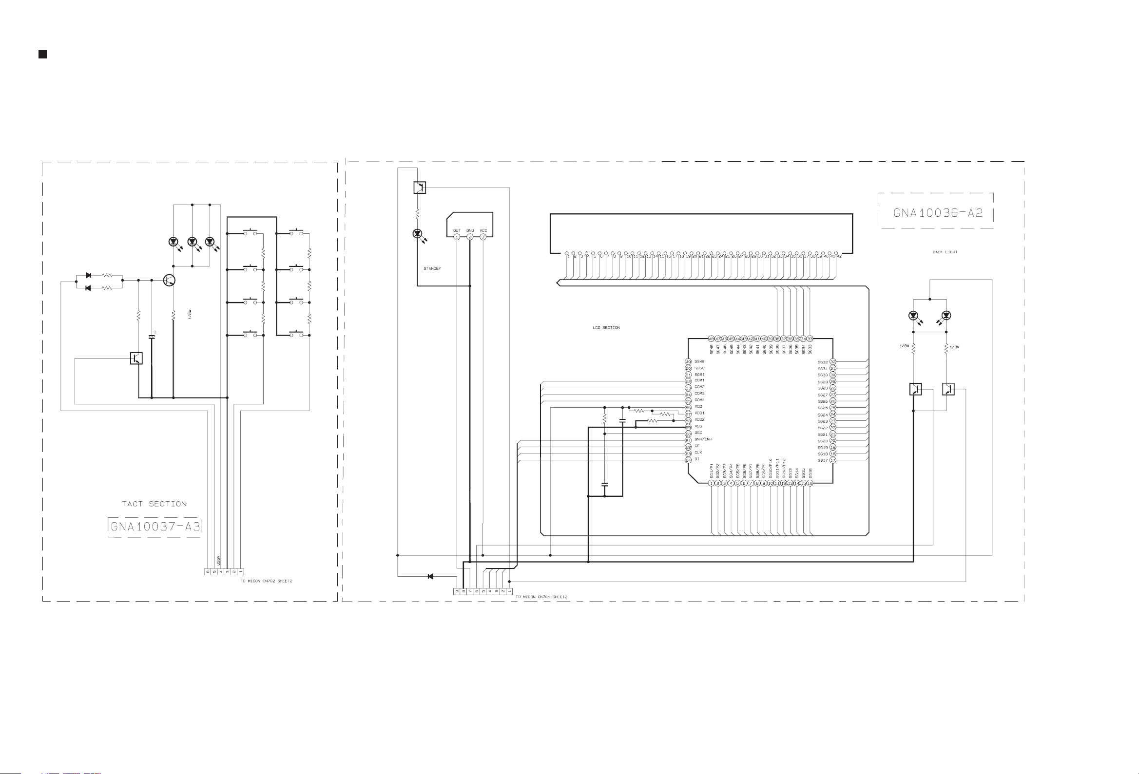
Key switch section
KEY0
S2501 to S2508
KEY4
KEY MATRIX
Q2501,Q2502
D2501 to D2503
TP.LED
POUT
LED
LCD section
DI221
LCD DISPLAY
COM1 to COM4
SG1 to SG38
IC221
/INH
LCDCS
LCDCLK
LCDDATA
CD
FM/AM
LINE
CN431
CN432
CN702
CN251
CN701
CN221
IC702
EEPROM
Q4102
Q4202
Q4302
KEY0
KEY4
TP.LED
POUT
Q7001
RESET
Q7002
/INH
LCDCS
LCDCK
LCDDATA
REM
POUT
LEDDIM
LCD DRIVER
IC241
REM
REMOCON
Q2411,D2411
POUT
STANDBY LED
Q2201,Q2202
D2201,D2202
BACK LIGHT
LEDDIM
POUT
DOOR
DRIVE
MOTOR
M
CN511
S7001
DOOR
DETECT
IC511
DOOR
MOTOR
DRIVER
OPEN
CLOSE
MOTOR1
MOTOR2
FAN
MOTOR
Q7004
Q7005
SW9V
CD8V
US6V
M
Main section
CN707
CN316
CDL/R
VOLCE
VOLCK
CN703
CN313
VOLDATA
CN705
CN315
DABON
CN704
CN314
CN811
E.VOLUME
FAN2
Q8102,Q8103
FAN DRIVE
IC303
SAFTY1
FCD
SAFTY2
FTU
SW10
LOPOUT
ROPOUT
LSEL0
RSEL0
L5
R5
TUNERL/R
Q3101,Q3201,Q3303
Q3601
Q3602
S.BASS
3.3V
IC281
Q2801,Q2802
3.3V REG.
CD8V
Q3501,Q3502
CD8V REG.
TU9V
Q3801,Q3802
TU9V REG.
SW9V
Q3401,Q3402
SW9V REG.
MUTING
SMUTE
L-BAND
SAFTY1
IC452,Q4501
QP LINK
QPLINK
Q8101
Q8104
QPPOWER
12V
Q5801,Q5802
12V REG.
DAB6V
IC911
DAB6V REG.
US5V
IC811
US5V REG.
US6V
IC711
US6V REG.
D1001
DIODE BRIDGE
CN311
IC301
POWER AMP.
POUT
Q3311
Q3312
Q4604 to Q4606
LINE OUT VOLUME
LVOL
TUCE, TUCLK, TUDI, TUDO
RDSCLK, RDSDAT
DATARX
DATATX
DABREST
RSW
RY101
Q1001
RELAY
Main section (Terminal)
CN312
L+/R+/-
Q4601 to Q4603
LINE OUT MUTING
IC451
LINE IN AMP.
CN911
TUNER
UNIT
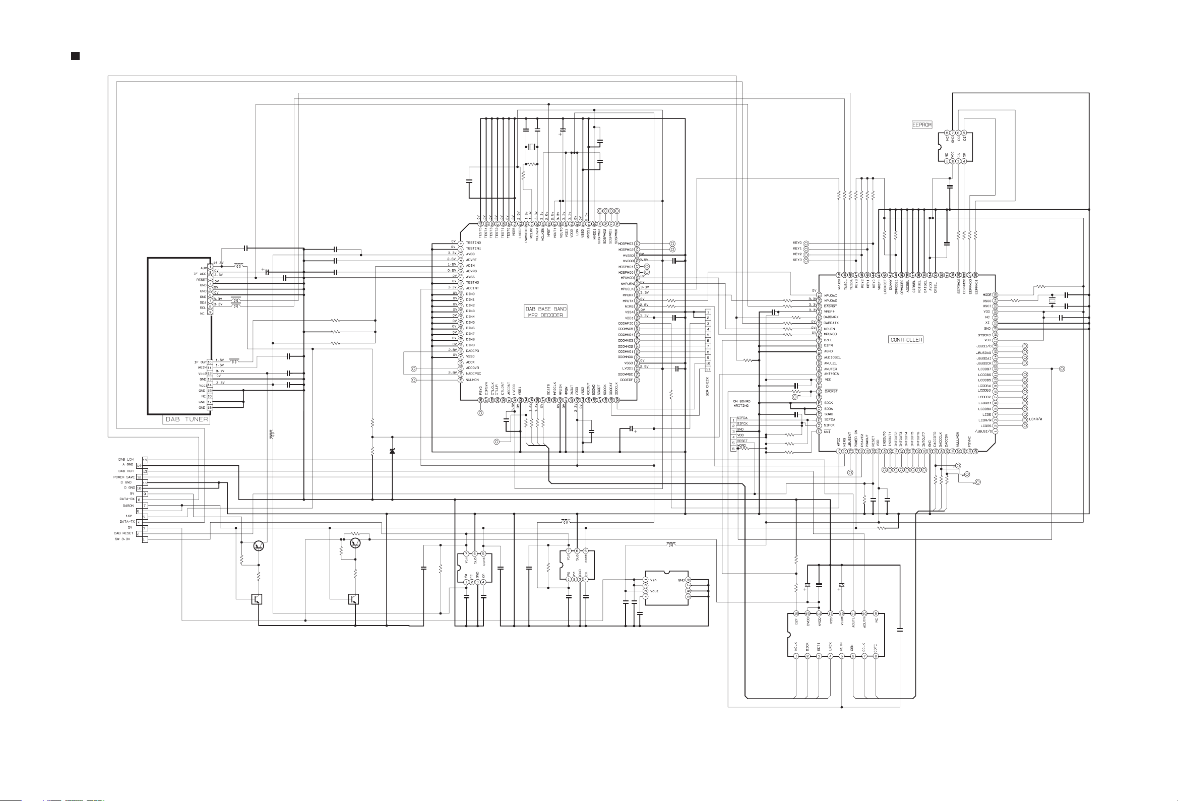
DAB Module section
Vcc2 IF OUT
Q344
Q345
DABON
CN342
CN912
CN102
DATARX
DATATX
DABRESET
DABL/R
IC350,IC353,IC354
3.3V REG.
US5V
T901
POWER
TRANS.
J3301 J3001
J4352
LMUTE
J4351 CN101
TU301
DAB TUNER
DABRST
IC321
DAB BASE BAND
MP2 DECODER
X321
24.576MHz
CONTROLLER
DZFL
DACCSN
SMCK
DACCLK
SCLK
DACCDTO
SDAT1
DACRST
SLRCK
IC352
DAC
3.3V
EEPROM
CN103
TO
HEADPHONE
TO
SPEAKER
LINE OUT
LINE IN
WFIC
NIRQ
MPUDAI
MPUDAO
MPUEN
MPUMOD
MPUCK
ANT+BIN
TUSCL
TUSDA
IC371
X371
19.6608MHz
EEPRMCS
EEPRMCK
EEPRMDO
EEPRMDI
IC391
AC IN
2-1
Page 12
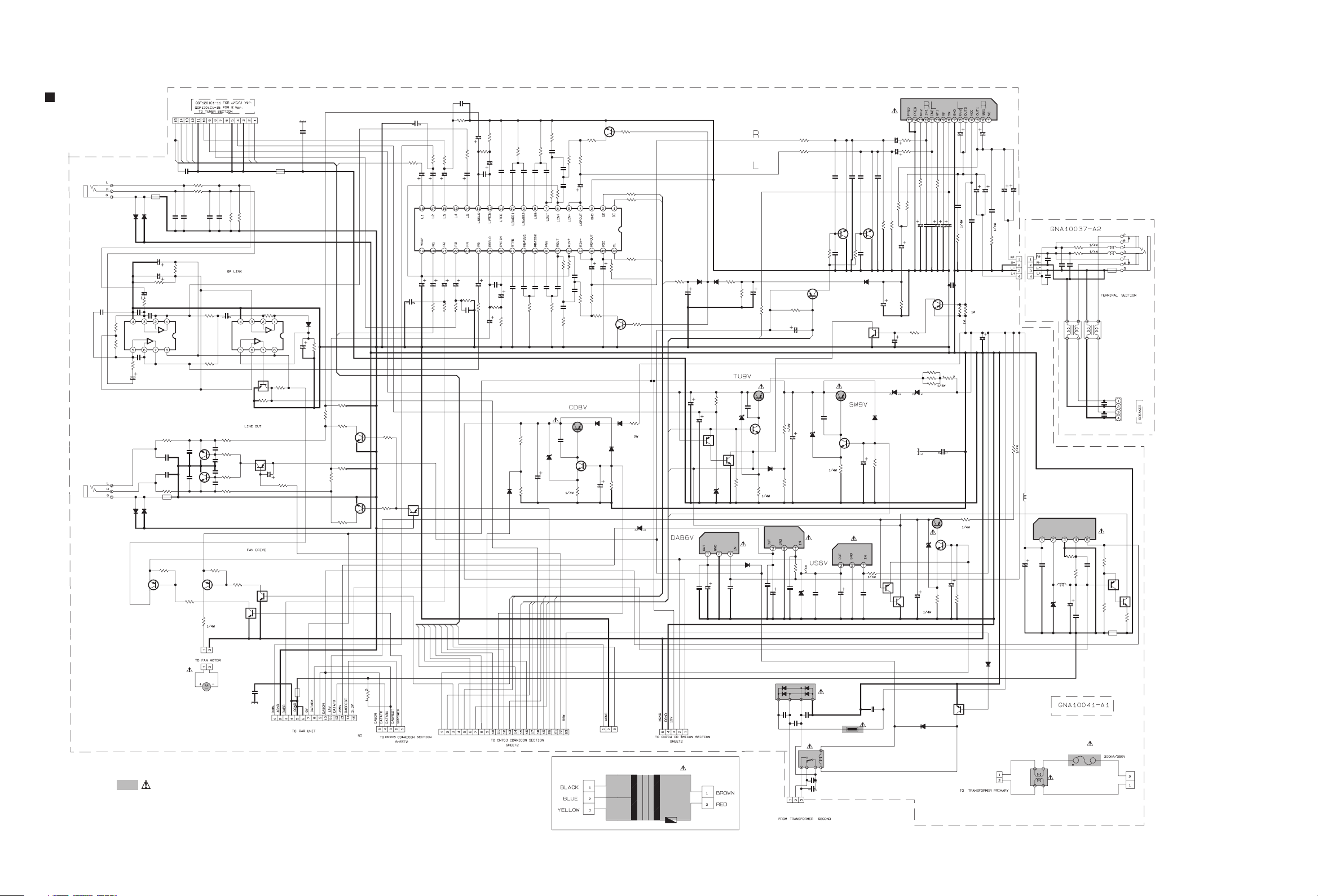
Standard schematic diagrams
Primary section
CN911
J4351
QNS0271-001
C4509
NI
J4352
QNS0271-001
R4508
R4509
TUDI
TUCE
TUDO
TUCLK
VCC9V
TUNERL
C9004
1000p
R4251
13K
R4151
13K
NI
NI
C4151
C4251
R4506
47K
R4502
4.7K
4.7K
R4501
2SC3661-X
Q4601
NINI
C4604C4605
1K
Q4602
2SC3661-X
R8102
Q8102
2SA1530A/QR/-X
R8106
1K
R8104
51
!
QAR0408-001
C4508
NI
100K
IC451
NJM4565M-WE
100K
C4507
R4511
D4602
1SS133-T2
D4353
100P
1K
C4505
2.2/50
NI
K4351
0
1SS133-T2
D4352
C4503
C4502
R4507
C4504
2.2/50
R4510
1K
100P
C4506
R4601
C4601
C4602
R4602
D4601
NI
R8101
Q8101
2SA1530A/QR/-X
47/16
47/16
0
47K
1K
470P
470P
K4602
10K
Parts are safety assurance parts.
When replacing those parts make
sure to use the specified one.
TUNERR
220P
220P
C4152
C4252
C4510
0.22
R4603
C4606
R4604
C4607
R4605
100PNI
C4608C4609
2.2K
R4606
300
10K
CN811
QGA2001C1-02
51K
R4152
300
NI
2.2K
100P
R8105
RT1N431C-X
3.3V
RDSCLK
51K
R4252
IC452
NJM4565M-WE
1K
Q8104
C9005
CN912
QGF1040C1-15
QGF1208C1-15
RDSDAT
R4503
Q4501
RT1N44HC-X
R4512
15K
Q4603
RT1P441C-X
K901
0
220K
1SS133-T2
R4505
2.2K
C4603
10/25
R4607
1K
Q8103
RT1N431C-X
D4501
10/25
C4501
K902
NQR0502-002X
C9002
1000P
100K
R4504
R4612
3.6K
2SC3661-X
R4613
2SC3661-X
R4611
CDL
CDR
R4608
R4610
3.3K
Q4604
R4609
47K
3.6K
Q4605
QGF1040C1-05
C3151
0.022
C3158
NI
R3154
1K
C3149
10/25
C3258
C3342
NI
47K
R4614
4.7K
Q4606
RT1P141C-X
R4615
4.7K
3.3K
4.7K
R901
CN315
C3146
220/10
R3153
C3249
R3254
10/25
1K
1K
R3152
4.7/50
C3246
4.7/50
1K
1K
R3253
POUT
L-BAND
CN313
QGF1040C1-23
C3148
FAN2
0.1/50
C3248
R3252
10K
R3155
C3145
0.1/50
1K
VOLCK
4.7/50
10K
R3255
C3251
0.022
S.BASS
R3151
TUCE
1K
C3156
R3150
390P
C3157
C3245
R3251
SMUTE
4.7/50
15k
4.7/50
1K
TUDO
C3155
C3256
R3149
4.7/50
C3257
R3250
4.7/50
SAFTY2
TUDI
390P
15k
3.3K
3.3K
R3249
D3502
FCD
R3141
7.5K
C3144
0.0027
4.7/50
C3255
1SS133-T2
TUCLK
0.0027
C3244
FTU
C3143
0.1
RDSCLK
C3142
0.1
C3243
R3503
39K
R3504
18K
RDSDAT
SAFTY1
R3140
NI
0.1
NI
C3141
IC303
LC75345M-X
0.1
C3242
7.5k
R3241
C3503
100/16
SW10
QPLINK
C3140
C3241
R3240
VOLCE
NI
LVOL
R3147
6.2K
C3154
0.47
0.068
C3153
NI
C3152
1.8K
R3146
R3148
1.8k
R3246
NI
C3240
NI
!
D3501
MTZJ5.6A-T2
R3502
VOLDATA
LMUTE
220K
C3253
C3254
R3247
6.2k
C3502
0.01
270
R3248
0.47
0.068
R3143
22K
1.5K
R3145
R3144
0.068
C3150
220K
0.068
C3252
R3245
Q3501
KTA1046/Y/
Q3502
2SC3928A/QR/-X
C3501
10/25
2.2K
22/16
22/16
C3250
C3341
220/10
1.5k
2.2k
R3244
R3243
22K
R3507
1F4G01F4G
D3503
1SS133-T2
CDR
Q3602
2SC3661-X
R3342
4.7K
4.7K
R3343
R3344
100
R3341
Q3601 R3242
2SC3661-X
R3508
R3501
6.8K
CDL
CN316
QJP007-031700-E
R3142
47K
VOLCE
VOLDATA
4.7K
VOLCK
47K
R3506
22
D8101
1SS133-T2
T901
QQT0531-001
S.BASS
R3310
22K
FTU
SAFTY1
SW10
US6V
CD8V
!
D3306
1SS133-T2
C3312
10/25
C3802
100/16
47/6.3
C9103
0.1
CN314
QGA2001C1-05
D3305
1SS133-T2
C3801
Q3803
RT1P430C-X
D3802
MTZJ3.3B-T2
IC911
KIA78DL06PI
C9102
100/16
R3803
820
Q3804
R3309
120K
R3308
220K
Q3801
KTB772/Y/
D3801
RT1N141C-X
C9101
0.1
C3311
1/50
R3305
10K
C3803
0.01
MTZJ5.6B-T2
R3801
20K
R3802
470
!
D7102
1SS133-T2
POUT
!
Q3802
2SC3928A/QR/-X
D3403
1SS133-T2
KIA78DL06PI
C8103
0.1
C1001
0.01
R3206
R3106
Q3303
2SA1530A/QR/-X
9.1K
R3411R3412
100/16
C3404
3.6K
IC811
C8101
0.1
C8102
100/16
D1001
CN102
QGA3901C1-03
R3306
5.6K
C3310
22/16
R8103
FL402
33
C1005
0.01
6.8K
6.8K
SMUTE
D3402
MTZJ6.2B-T2
!
D7101
MTZJ8.2B-T2
C1004
0.01
!
0.1
C7103
C1006
C1007
100/16
!
NI
NI
NI
C3209
Q3201
2.2K
R3205
470P
C3211
!
C3402
0.01
R3401
470
KIA78DL06PI
C7102
RY101
QSK0155-001
NI
NI
C3210
C3109
2SC3661-X
2.2K
R3105
D3302
1SS133-T2
Q3312
RT1N141C-X
Q3401
KTB772/Y/
Q3402
2SC3928A/QR/-X
C3401
10/25
!
IC711
TH101
RUEF250
C3111
!
Q3101
2SC3661-X
470P
C3309
0.1/50
R3307
2.2
C7101
0.1
C1008
0.01
C3208
10/50
C3108
10/50
NI
C3110
47K
47K
R3104
R3204
R3301
4.7K
D3401
1SS133-T2
R3402
6.8K
Q5803
RT1P430C-X
Q5804
RT1N141C-X
!
R3209
1K
R3109
1K
18K
18K
R3203
R3103
1/50
C3305
C3313
22/25
200
R3202
100/16
C3206
Q3311
2SA1530A/QR/-X
R3312
68k
R3805
R3804
R3806
D3404D3405
1SS244-T21SS244-T2
D5801
C5802
100/16
R5802
1SS133-T2
D1002
820
R3102
330P
330P
100/16
C3207
C3107
C3106
C9003
0.0033
200
200
C9001
!
MTZJ10B-T2
470
RT1N430C-X
IC301
BA5417
820
47/16
220/16
C3304
C3303
R3807
QUY150-050Y
0.001
Q5801
KTA1046/Y/
Q5802
2SC3928A/QR/-X
C5801
10/25
Q1001
C3104
100/16
0.022
C3105
R3101
2.2
0.33
R3313
R5803
18
R5801
5.6K
QGA7901F1-02
C3302
R3311
0.33
C3101
0.1
22/50
C3204
C3102
CN103
100/16
C3201
22/50
2200/16
0.022
C3205
2.2
R3201
CN311
QGB2510J1-04
C3301
6800/25
D1003
QUY150-050Y
C3202
18
R5804
2200/16
220P
C3213
CN312
QGB2510K2-04
L2802
QQL244K-100Z
100/50
C2801
LF101
QQR1645-001
C3113
220P
L3202
QQR0797-002
BD9703FP-X
0.1
C2802
D2801
RB051L-40-X
!
R2802
C3112
IC281
1K
L2801
R3108
R3208
R2801
2.4K
NI
QQL28AK-470
C2804
120
120
NI
C3212
C2803
470/50
0.1
C2805
!
F1001
QMF51W2-R20-J8
L3101
L3201
QQR0797-002
C3214
3300P
C3114
3300P
!
0.1
R2804
NQR0502-002X
J3301
QNS0272-001
4.7u
4.7u
K3301
NQR0502-002X
L3102
QNB0295-002
J3001
R+
R-
L+
L-
R2803
6.8K
Q2801
15K
Q2802
RT1N141C-X
K2801
QGA7901F1-02
RT1P430C-X
0
R2805
CN101
2-2
Page 13
Micon section
C4006
1/50
R4007 R4006
FAN2
L-BAND
R7054 R7053
1K 4.7K
R7055
R7056
R7057
R7058
R7059
R7060
R7061
R7062
R7063
R7064
R7065
R7066
R7067
Q7003
L7004
1K
1K
22K
4.7K
2.2K
4.3K
22K
1K
1K
2.2K
2.2K
10K
10K
R7068
2SA1530A/QR/-X
10
100K
R7016
R7017
R7018
R7019
R7020
L7002
10
L7003
100K
4.7
1K
100K
1K
10K
C7009
2.2K
2.2K
2.2K
2.2K
2.2K
2.2K
0.1
R7006
R7007
R7008
R7009
R7010
R7011
R7012
KEY0
QPLINK
LVOL
LMUTE
FTU
SW10
SAFTY1
SAFTY2
VOLDATA
VOLCE
VOLCK
FCD
SMUTE
POUT
RSW
C7014
0.001
C7015
0.047
IC702
BR24L02F-W-X
R4103
22K
100P
R4204
1M
R4201
C4203
R4203
68K
100P
22K
R4303
C4303
68K
R4301
100P
R4304
1M
1M
IC401
NJM4565M-WE
22K
680P
C4003
C4302
R4003
30K 30K
R4001R4005
100K100K
R4002
R4008
68K
R4101C4103
R4104
1M
IC402
NJM4565M-WE
C4202
2P 1M
22K
C4301
5P
R4302
1M
2P
220K
C4004
C4102
2P
R4202
C4201
5P
R4305
10K
C4101
5P
R4102
1M
10/16
C4005
10/16
Q4011
RT1N140C-X
RT1N140C-X
R4016
100K
RT1N431C-X
Q4201
R4012
220K
R4017
100K
Q4101
RT1N140C-X
R4013
47K
C4012
68P
Q4301
Q4012
RT3CLLM/EF/-X
R4014
22K
R4015
10K
CN431
QGF1038F2-05X
CN432
QGF1040F1-05
100K
R4112
RT3WLMM/EF/-X
1
C4111
1
C4211
RT3WLMM/EF/-X
100K
R4212
100K
R4312
Q4302
RT3WLMM/EF/-X
1
NI
C4312
C4311
Q4102
Q4202
NI
C4112
NI
C4212
R4314
R4114R4011
R4315
R4214
10K
1M
R4316
R4113
100K
10K1M
C4011
100/16
1M
C4313
100/16
10K
100K
R4213
R4313
100K
C4314
100/16
2.2K
R7069
100/10
2.2K
R7013
3.3K
KEY4
C7006
TUCE
RDSDAT
2.2K
2.2K
R7074
R7075
IC701
MN101C49KAF
QAX0902-001
C7007
22P
X7001
C7005
TUDI
TUDO
TUCLK
2.2K
2.2K
2.2K
R7072
R7073
R7071
1K
R7022
/INH
LCDDATA
C7008
22P
L7001
D7004
0.1101SS133-T2
1K1K100
R7023
R7024
R7025
LCDCK
C7004
2200/6.3
K7001
NQR0389-003X
2.2K
R7048
100
R7026
1K
R7047
100
R7027
R7005
330
LCDCS
1K
R7028
C7003
150P
C7010
C7011
C7012
C7013
22P
22P
22P
22P
R7004
100K
MTZJ5.1B-T2
Q7004
R7070
R7034
R7045
R7044
R7043
R7042
R7040
R7039
R7041
R7038
R7046
R7035
R7033
R7032
R7031
R7030
R7029
R7037
D7003
1SS133-T2
D7002
Q7002
RT1N430C-X
RT1N141C-X
R7079
10K
C7017
0.001
C7002
R7002
10K
2.2K
2.2K
0
0
2.2K
0
1K
2.2k
2.2k
2.2K
4.7K
2.2K
2.2K
1K
2.2K
2.2K
2.2/50
1K
R7036
1K
Q7005
RT1N141C-X
R7080
10K
CDSW
CDREST
MLD
MCLK
STAT
MDATA
DABTX
DABRX
DABON
DABREST
QPPOWER
IRQ
RDSCLK
S.BASS
10K
RT1N430C-X
LEDDIM
Q7001
R7001
10K
TP.LED
REM
C7001
10/16
D7001
1SS133-T2
R7052
R7051
R7050
R7049
C5102
10K
10K
10K
0
R7076
IC511
LB1641
S7001
QSW0933-001
/INH
LCDCK
LCDCS
LEDDIM
REM
KEY0
KEY4
CN511
QGA2501C1-02
CN701
QGF1040F1-09
CN702
QGF1040F1-06
CN706
QJK018-060601-E
0.01
C5101
0.1
D5101
MTZJ6.8B-T2
10K
LCDDATA
TP.LED
L-BAND
POUT
FAN2
VOLCK
TUCE
S.BASS
SMUTE
TUDO
CN703
SAFTY2
TUDI
QGF1040F1-23
C7016
0.001
K7002
NQR0389-003X
STAT
CD8V
CDL
IRQ
CDR
CDSW
MLD
MCLK
MDATA
AGND
CN707
QGA2001F1-03
CDREST
TUCLK
FTU
RDSCLK
SAFTY1
SW10
RDSDAT
QPLINK
CN705
QGF1040F1-05
FCD
DABON
DABTX
DABREST
DABRX
QPPOWER
LMUTE
RSW
VOLCE
LVOL
VOLDATA
US6V
MGND
DGND
10V
CN704
QJK043-050400-E
2-3
Page 14
Front section
D2504
QUY150-050Y
D2505
NI
R2509
7.5K
R2508
NI
Q2502
RT1N144C-X
3.9K
R2507
220/16
C2501
SLI-343DC3F
SLI-343DC3F
D2501
D2502
Q2501
2SC3928A/QR/-X
27
R2510
SLI-343DC3F
D2503
S2504
QSW1120-001Z
R2503
1.2K
S2503
QSW1120-001Z
R2502
510
S2502
QSW1120-001Z
R2501
430
S2501
QSW1120-001Z
S2508
QSW1120-001Z
R2506
1.2K
S2507
QSW1120-001Z
R2505
510
S2506
QSW1120-001Z
R2504
430
S2505
QSW1120-001Z
Q2411
RT1P141C-X
R2411
390
D2411
SLR-342VC-T
IC241
RPM7138-H9
/INH
LCDCS
LCDCLK
LCDDATA
COM1
COM2
COM3
COM4
COM1
COM2
COM3
COM4
SG1
R2203
270K
SG2
SG3
0.022
SG4
C2201
SG5
SG6
R2206
SG7
SG8
R2208
SG9
1K
SG10
SG11
R2207
1K
SG12
QLD0429-002
SG14
SG13
1K
DI221
SG15
SG16
SG17
SG18
SG19
SG20
SG21
SG22
SG23
SG24
SG25
SG28
SG27
SG26
IC221
PT6524LQ-L
SG29
SG38
SG30
SG37
SG31
SG36
SG32
SG35
SG33
SG34
SG34
SG33
SG35
SG36
SG37
SG38
SG32
SG31
SG30
SG29
SG28
SG27
SG26
SG25
SG24
SG23
SG22
SG21
SG20
SG19
SG18
SG17
D2202
NSPW310BS/B2RST
R2202
100
Q2201 Q2202
RT1N144C-X
D2201
NSPW310BS/B2RST
R2201
100
RT1N144C-X
PT.LED
GND
KEY4
KEY0
CN251
QGF1040F1-06
D2203
1SS133-T2
US6V
GND
REM
LCDCLK
LCDCS
/INH
POUT
LCDDATA
QGF1040F1-09
2-4
CN221
C2202
100P
SG1
SG2
SG3
SG4
SG5
SG6
SG7
SG8
SG9
SG10
SG11
SG12
SG13
SG14
SG15
SG16
Page 15
DAB section
CN342
QGF1041C2-15W
TU301
QAU0468-001
L301
NQR0129-003X
L302
L303
NQR0129-003X
L304
Q345
RT1N141C-X
C311
0.1
NQR0129-003X
NQR0129-003X
Q344
R344
10K
C301
NI
C302
L341
2SA1530A/QR/-X
R345
1K
0.1
0.01
C303
0.1
C305
1
C306
NQL114K-100X
R301
R302
R303
C308
C309
C310
R346
NI
R313
X321
NAX0651-001X
R328
1M
680
1
C332
1
0.1
0.1
220
47K
47K
ADCOVR
NULMON
FSYO
C347
IC350
SMCK
NI
C350
NI
R347
D341
UDZS3.6B-X
R343 R342
15K 47K
0
Q346
NI
NI
Q347
NI
1
C348
R281
0
1
R327
IC321
MN66720DCUC
220
220
220
1
R320
SMCK
C361
R321
SLRCK
R322
SCLK
R323
SDAT1
220
NQL114K-100X
L342
0
R282
1
C362
IC353
NI
C321
1
0.1
C349
SDSPMO3
C322
C363
NI
1
11
C328C327
SDSPMO1
SDSPMO2
SDSPMO0
C323
10/16
1
C313
1
C312
L343
NQL114K-100X
RT9167A-33PS-X
C366
0.1
C326
MDSPMO1
MDSPMO0
R326
C325
IC354
MDSPMO3
MDSPMO2
1
220
220
R325
1
C324
1
R324
220
QGF1041C2-11W
CN321
R310
4.7K
CN371
QGF1041C2-06W
R312
NI
C375
R389
R390
0.1
R398
R391
R392
R397
R399
DACRST
C376
C377
R393
4.7K
R394
R395
IC391
BR93L76F-W-X
220
220
220
4.7K
4.7K
4.7K
4.7K
R388
R387
R386
R385
R384
R383
R382
NI
0
R381
R380
220
220
220
220
220
220
0.1
220
22P
4.7K
10K
JBUSINT
NI
R311
C352
18K 39K
R366 R367
47/10
C353
1
IC352
AK4387ET-X
C354
47/10
0.1
C378
R396
4.7K
INDO0
0.1
IC371
MN102H60KAE
INDO3
INDO2
INDO1
C379
C280
NI
INDO4
INDO5
INDO6
INDO7
220
220
R369
R368
DACCDTO
DACCCLK
0.1
C391
220
R370
DACCSN
C374
0.1
220
220
R378
R379
DACCDTO
220
220
R376
R377
DACCCLK
DACCSN
R374
680
R375
10K
X371
JBUSI/O
JBUSDAO
JBUSDAI
JBUSSCK
LCDDB6
LCDDB5
LCDDB4
LCDDB3
LCDDB2
LCDDB1
LCDDB0
LCDE
LCDRS
C373
15P
NAX0650-001X
C372
15P
C371
1
LCDDB7
C329
22/10
22P
30P
C331
C330
SMCK
SCLK
SDAT1
SLRCK
DACCSN
DACCCLK
DACCDTO
2-5
Page 16
CD section
CN602
QGA1501C5-06W
SP-
SP+
CDSW
TRVTRV+
FO+
FO-
TR-
TR+
NI
NI
C647
C646
0
C650
100/16
C649
0.1
C648
IC601
AN41012A-W
KTA1273/Y/-T
68P
R669
8.2K
Q601R659 R658
R657
0
0
220/6.3
C651
R655
5.6K
R656
3.3K
D601
QUY150-050Y
CD8V
CDSW
CDR
CDL
IRQ
CDREST
STAT
MLD
MDATA
MCLK
DGND
AGND
MGND
US6V
CN601
QGF1007F4-16
VR
R660
C645
0.01
C644
SP+
SP-
TRV-
TRV+
B+D
F
A+C
E
VREF
LD
PD
FO+
100
TR+
TRFO-
F
E
B+D
A+C
PD
LD
VREF
220/10
NI
C643
R654
C642
22
0.1
R609
R610
0
R611
R612
4.7
0
0
Q602
2SA1530A/QR/-X
C609
47/6.3
0
R668
C608
NI
C611
47/6.3
R619
47K
R653
4.7K
TP601
NI
C607
C610
0.33
R620
R613
R614
R616
R617
0
2700P
C603
R621
R652
3.3K
NI
C606
270P
4.7K
R608
NI
NI
1.8K
1.8K
C612
R651
R648
8.2K
R645
R642
33K
R607
47/6.3
0.0022
0.0056
C639
0.0068
C638
0.0022
C613
18K
C641
C640
R606
39K
C602
390P
3300P
0
C615
0.33
27K
R604
C614
R650
R647
R644
0
0
C604
0.1
C616
10
R622
12K
R641
15K
R640
5.6K
R615
R618
0
0.022
C605
0.022
47/6.3
0
R623
47/6.3
0.1
C653
TRVP
SPOUT
R601
10K
TP613
TP614
TP615
TP612
TP611
C660
C661
0.01
R663
0
R7077
0.1
IC604
SN74LVC07ANS-X
0
D602
1SS133-T2
1M
R634
2.2K
X601
QAX0901-001Z
CDREST
MDATA
MCLK
MLD
IRQ
STAT
1K
R661
1K
R662
C635
0.1
R636 R637
220
C632
0.22
R635
4.7K
1K
R633
1K
R632
R631
2.2K
R630
2.2K
R629
2.2K
R628
4.7K
4.7K
R627
4.7K
R626
1K
1K
R671
0.1
0.1
47/6.3
47/6.3
C628
C629
C630
C631
0.0022
C626
C627
47/6.3
0.1
C633
0.001
CDR
C636
C637
0.0022
R649
5.6K
3.3K
R646
1K
15K
R643
5.6K
FOP
TRP
SPOUT
TRVP
TRP
FOP
R605
0
IC602
MN6627945EE
C617
0.1
C618
TP602
680P
C619
0.015
C620
0.1
C621
0.001
C622
C623
C624
R624
R625
820
0.082
0.1
220/6.3
82K
R670
C625
CDL
2-6
Page 17
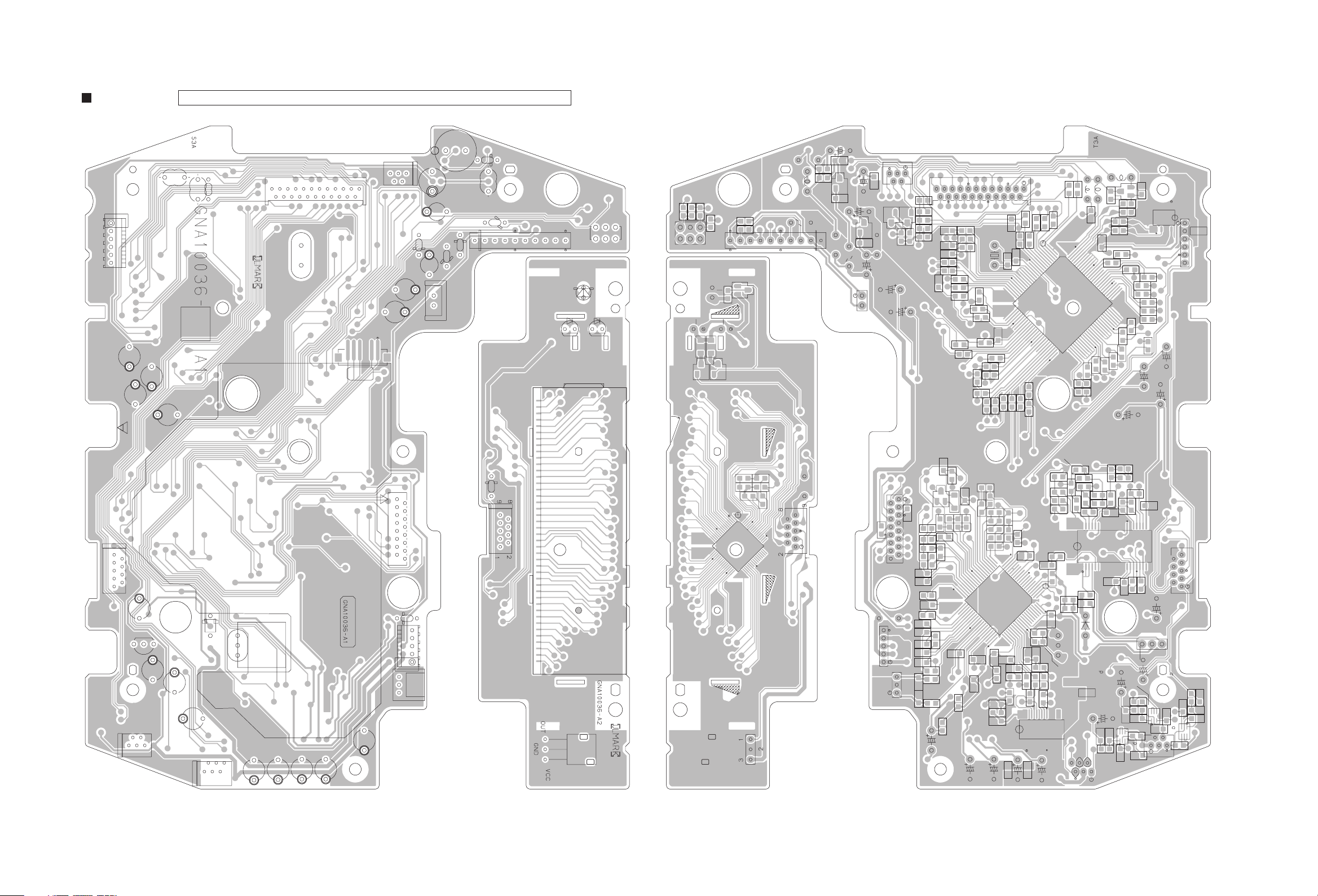
Printed circuit boards
Main board
Lead free solder used in the board (material : Sn-Ag-Cu, melting point : 219 Centigrade)
forward side reverse side
(CD & Micon board) (CD & Micon board)
C611
CN706
C644
C609
C650
L7004
L7003
L7002
CN703
X7001
CN602
CN705
C616
C612
C7002
CN511
D7001
C7001
C7006
D7002
C7004
D7003
L7001
D5101
D7004
IC511
D2201
D2411
D2202
S7001
R7049
S7001
R2202
D2202
Q2201
R7052
IC511
R2411
D2411
Q2202
R2201
D2201
R7051
Q2411
C5101
C5102
D7004
R7050
D5101
L7001
R7005
R7004
Q7002
R7002
Q7001
D7003
C7004
C7003
D7002
C7002
C7006
C7005
R7001
Q7004
Q7005
C7001
CN511
D7001
C612
CN705
R7079
R7018
R7020
R7016
R7017
R7019
R7080
C616
C7013
C7012
C7011
R7025
R7026
C7010
R7033
R7035
R7030
R7031
R7042
R7029
R7040
R7043
R7032
R7039
R7044
R7022
R7023
R7024
R7045
R7027
R7037
R7028
R7034
R7069
R7013
X7001
C7008
CN703
R7011
R7012
R7038
R7041
C7007
C7017
R7046
R7070
R7010
R7007
R7006
R7067
R7009
R7066
R7065
R7064
R7008
C7009
L7002
R7048
R7047
L7003
C7015
R7071
R7068
R7062
R7072
L7004
R7063
R7073
R7074
IC701
R7075
C650
R7059
R7060
R7054
R7053
Q7003
R7058
C7014
R7061
R7076
C609
R7057
R7056
R7055
IC702
K7001
CN706
C611
C644
CN432
CN701
C4011
C651
Q601
CN702
C4313
D601
C4314
X601
C631
C630
C625
C626
C624
CN601
CN704
CN707
D602
D2203
CN221
DI221
IC241
R2203
C2202
IC221
R2208
IC241
R2206
C2201
R2207
D2203
CN221
R611
CN704
CN707
D602
C621
C623
R614
R613
C617
C615
C610
C622
C636 C637
R617
R671
R660
Q602
R624
R670
R621
C613
C618
C619
C620
R625
R619
R615
C624
R618
C627
R623
R668
R610
C626
IC602
C629
R626
R622
R612
C608
C660
R663
C661
C614
C628
R608
C607
R627
C606
R629
C625
R609
R628
R630
R607
C602
R605
R606
C605
C604
C633
R7077
C630
C632
C603
R604
C641
R620
C653
R7036
R651
R649
R650
R656
R635
C640
R646
C631
C7016
R637
R636
R634
IC604
R658
R657
CN702
C635
R644
R655
R601
R631
R662
C649
X601
R632
R661
R647
R648
C4312
R4316
R652
K7002
R643
C639
R645
R669
R659
D601
C4314
R4314
C648
Q4302
R633
C4311
R4313
R653
CN432
R4212
R4214
C4212
R4315
R642
R640
C638
R641
R4112
C4313
R4312
C643
C642
C646
Q601
Q4202
R654
C645
C647
C4011
R4213
IC601
CN701
C651
Q4102
R4113
R4114
R4011
C4111
(LED board) (LED board)
2-7
Page 18
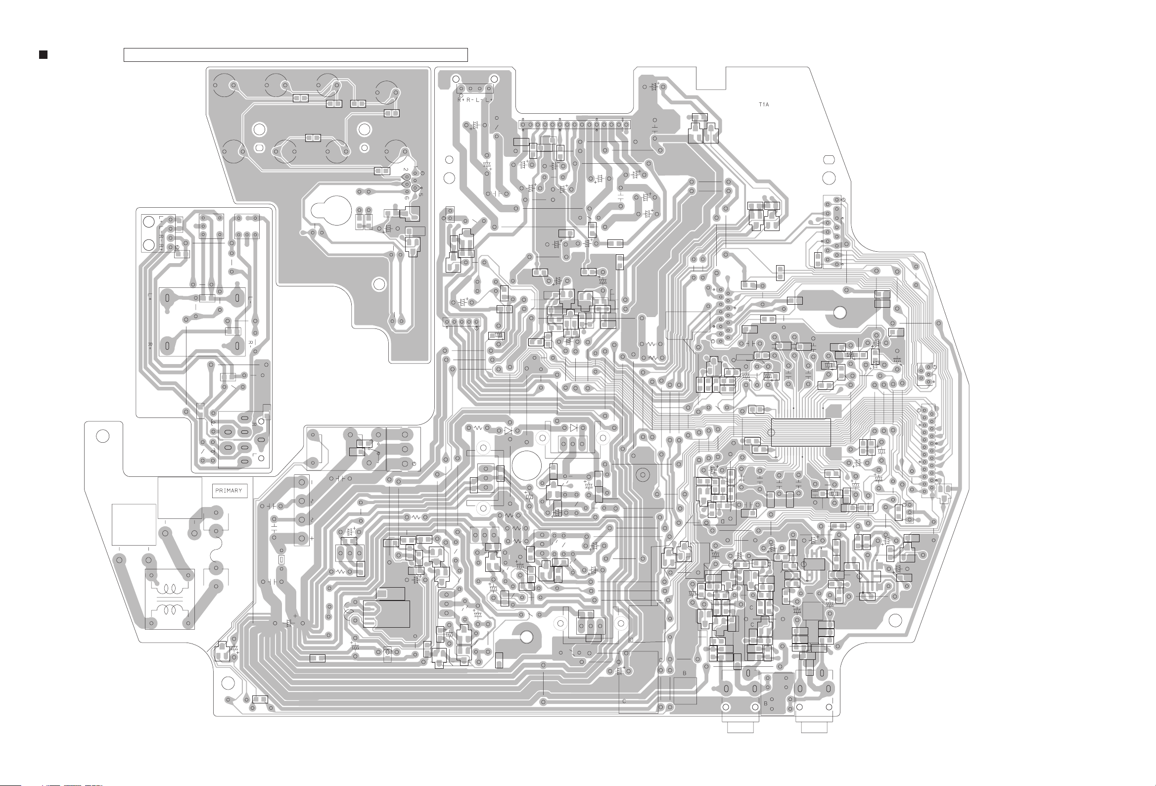
Sub board
Lead free solder used in the board (material : Sn-Ag-Cu, melting point : 219 Centigrade)
(tact switch & LED board)
(Speaker board)
CN103
CN312
J3001
LF101
CN101
C3113
C3213
C3112
R3108
C3114
C3214
L3201
S2508
L3101
Q1001
C3212
J3301
L3102
S2506
Z1001 Z1011
D1002
K3301
C1003
R3208
L3202
C1004
C1008
R1003
S2501
C3301
D1003
C1001
R2506
TH101
R2501
D2502
K2801
D1001
C8102
C8103
IC811
D3404
R2505
S2502
R8103
C1007
C1006
C1005
D3405
S2507
L2801
R2503
R2504
D2504
RY101
R2509
R2802
C8101
C2801
R2508
L2802
D2505
R2801
R2502
R2507
C2501
C2803
C2804
S2505
D2501
R2802
C2805
S2503S2504
D2503
C2802
R2804
R2510
Q2501
R3807
Q2502
R2803
CN251
CN102
D2801
IC281
R2805
Q5801
R5801
Q5804
C3101
CN811
R8105
Q8103
C3312
Q2801
CN314
Q2802
C5801
R5804
D5801
Q5802
Q5803
CN311
R3506
C9101
C3402
R5803
C3102
R3310
IC911
D3401
C5802
Q8102
R8102
D3305
D3306
Q3401
C3105
Q3402
C3401
R5802
C9001
R3308
D3402
R3402
R3101
R8104
R3309
R3806
(Power & Audio board)
R3102
C3107
C9003
C3207
R3202
C3309
R3206
Q3502
Q3802
C3502
D3403
R3201
R3301
Q3201
Q3303
R3306
R3501
D7101
C3106
C3303
R3507
Q3501
C3501
R3801
C3304
C3311
C9103
R3805
C3803
C3404
R3411
R3401
C3206
R3209
D3302
R3204
R3508
C9102
C3208
R3804
R3412
C3210
C3211
R3205
C3209
D3503
Q3801
R3307
D3801
D3802
C3305
D3501
R3803
R3802
C7101
R3103
R3109
Q3101
C3310
C3503
R3502
C3802
C7103
C3104
R3503
C7102
C3111
R3105
C3801
IC711
C3205
R3203
C3108
D3502
C3109
R3106
C3110
R3104
R3504
C3204
R3305
R3142
Q3602
IC301
R3143
C4602
C3202
W302
R3145
C3153
Q4605
C4608
Q4602
C4609
C4605
C3313
C3201
R3313
R3311
R4615R4614
R4609
R4613
R4611
R4605
R3144
C3152
R4606
R4602
C3302
R3148
R3146
Q3601
R3242
Q3803
R3243
Q3804
D7102
R4601
D4602
D4601
D4353
D4352
R3244
C3150
C4603
Q4603
C4606
C4604
C4601
R3312
R3245
C3253
C3252
R4608
R4612
R4607
Q4601
R4610
R4603
C4607
Q3312Q3311
D8101
R4604
R3341
Q4604
J4352
C3156
CN912
R3246
C3256
K4602
R8101
R3247
C3254
C3250
C3341
C3154
R3147
Q8101
K902
R3344
R3342
C3140
R3343
C3141
R3253
C3240
R3151
R8106
Q8104
R3240
R3140
C3145
R901
R3248
C3142
C4506
R4510
C9005
C3242
R3141
R4502
C4504
C3241
C3143
R3241
C3243
C4503
IC451
C4508
R4508
R4252
C4252
R4251
C9004
C3144
R3149
K4351
CN911
C4251
C3244
R3249
C3257
C3155
C3255
C3157
R3150
C4507
C3251
R3255
IC303
R3251
J4351
C4505
C3248
R3155
C3151
R4501
C4510
R4509
R4511
R4152
C4152
R4151
C4151
R3252
R4506
C4509
C9002
R3250
C3146
C3249
R3153
C3158
C3148
R4503
C4502
IC452
R3152
R4507
K901
R3254
C3149
C3245
R3154
C3246
R4505
C3258
C3342
CN315
CN313
Q4606
CN316
R4512
Q4501
C4501
R4504
D4501
2-8
Page 19

Touch board
Lead free solder used in the board (material : Sn-Ag-Cu, melting point : 219 Centigrade)
R4303
R4304
C4302
IC401
R4001
forward side
C4303
R4301
R4302
C4301
R4005
R4002
R4203
R4204
C4202
C4201
R4202
R4103
IC402
R4104
C4102
C4203
R4201
R4102
C4101
C4103
R4101
Q4101
C4005
reverse side
C4006
R4006
R4007
Q4201
Q4301
R4015
R4013
R4014
Q4012
CN431
R4012
R4008
C4004
R4016
R4017
C4012
R4305
Q4011
C4002
C4003
R4003
DAB board
Lead free solder used in the board (material : Sn-Ag-Cu, melting point : 219 Centigrade)
forward side
R282
Q346
Q345
IC350
C348
IC353
R347
R346
R345
R344
C349
Q344
Q347
C361
R313
C350
C347
C362 C363
R281
R367
R310
IC354
R311
C366
L341
L342
R343
C312
C352
R366
C280
C313
C354
R342
IC352
D341
L343
C353
C323
R320
R321
R322
R323
C308
C309
R302
R303
R301
C310
C331
C330
C321
C332
R327
R328
IC321
C306
C322
C305
L304
C303
C327
C328
R396
R388
C324
R326
R325
C325
R324
X321
C326
C329
R389
R397
R386
R398
R391
R392
R399
C376
C377
C391
C375
R395
R390
R394
R393
IC391
R387
R385
C378
C379
R384
R383
R381
R382
C374
L303
L302
R380
C302
R379
R378
R376
R377
C372
R374
R368
R375
IC371
C311
C301
X371
C373
C371
R369
R370
L301
reverse side
CN321
CN371
R312
CN342
TU301
2-9
Page 20

Victor Company of Japan, Limited
Audio/Video Systems Category 10-1,1chome,Ohwatari-machi,Maebashi-city,371-8543,Japan
(No.MB573SCH)
Printed in Japan
VPT
Page 21

PARTS LIST
UX-NB7DABB,UX-NB7DABE,UX-NB7DABEN
* All printed circuit boards and its assemblies are not available as service parts.
MB573
- Contents -
Exploded view of general assembly and parts list (Block No.M1)
Electrical parts list (Block No.01~04)
Packing materials and accessories parts list (Block No.M3)
3- 2
3- 5
3-12
3-1
Page 22

Exploded view of general assembly and parts list
e
o
74
71
72
p
73
g
68
30
67
h
c
F
70
31
m
S
45
f
41
B
j
30
31
66
A
69
30
E
29
k
F
n
k
30
Power & Audio board
38
37
36
n
38
37
j
50
Block No.
47
c
M
1
49
15
M
18
M
32
C
51
57
E
56
57
CD & Micon board
48
57
B
56
16
18
32
S
J
f
a
o
h
32
52
62
A
Sp
b
58
63
64
53
60
60
59
58
53
J
3-2
76
77
p
m
44
43
28
C
DAB board
75
54
Page 23

M
8
18
14
3
5
2
1
3.0mm
6
H
4
32
a
18
61
17
g
h
a
40
e
35
34
35
35
34
13
46
o
10
12
7
9
11
8
rd
58
54
32
Speaker
board
32
b
42
33
Touch board
39
G
33
21
H
e
Tact switch &
LED board
20
19
24
23
G
26
27
65
22
LED board
b
25
55
The parts without symbol number are not service.
3-3
Page 24

General Assembly
Symbol No. Part No. Part Name Description Local
1 GN10097-002A TOP PANEL
2 LV41821-001A FELT (x2)
3 GN30188-007A TOP PLATE
4 GN10100-009A CD DOOR
5 GN30187-001A DOO BASE
6 GN40101-001A PULLY
7 GN30186-001A BELT
8 VYH8090-001SC GEAR 1
9 GN40103-001A GEAR 2
10 QAR0374-001 LOADING MOTOR 12V DC
11 QYSPSP3004ZA SCREW M3 x 4mm(x2)
12 GN40110-001A DOOR BRACKET
13 QYSBSF3008ZA TAP SCREW M3 x 8mm(x2)
14 GN40114-001A CD CAUTION
15 QAL0857-001 MECHA
16 GN30006-002A SPACER
17 GN30006-001A SPACER
18 LV40770-002A INSULATOR (x3)
19 QLD0429-002 LCD MODULE
20 QNZ0868-003 RUBBER CONNE
21 GN20195-002A LCD BRACKET
22 GN20193-001A LENS BASE
23 GN20194-001A LENS
24 GN30184-002A LIGHT SHEET
25 GN30189-001A BRACKET
26 QYSBSF2608ZA TAP SCREW M2.6 x 8mm(x2)
27 QYSBST3008ZA TAP SCREW M3 x 8mm(x2)
28 QAU0413-001 TUNER FM/AM
29 QMPN380-170-JC POWER CORD(EU) 1.7m BLACK B
29 QMPK460-170-JN POWER CORD(EU) 1.7m BLACK E,EN
30 QYSBSF3008ZA TAP SCREW M3 x 8mm(x4)
31 QYSBST3008ZA TAP SCREW M3 x 8mm(x2)
32 QYSBSF2608ZA TAP SCREW M2.6 x 8mm(x5)
33 QYSBSF2608ZA TAP SCREW M2.6 x 8mm(x3)
34 QYSBSF2608ZA TAP SCREW M2.6 x 8mm(x2)
35 GN20200-004A LENS (x3)
36 QQT0531-001 POWER TRANSF
37 GN20196-001A TRANS BKT (x2)
38 QYSBSF3014ZA TAP SCREW M3 x 14mm(x4)
39 QUQ210-0505DJ-E FFC WIRE 5pin 5cm
40 QUQ210-0605CJ-E FFC WIRE 6pin 5cm
41 QUQ210-2306CJ-E FFC WIRE 23pin 6cm
42 QUQ210-0906DJ-E FFC WIRE 9pin 6cm
43 QUQ412-1505DJ-E FFC WIRE 15pin 5cm
44 QUQ210-1506DJ-E FFC WIRE 15pin 6cm
45 QUQ210-0506DJ-E FFC WIRE 5pin 6cm
46 WJM0017-003A-E WIRE
47 QAR0408-001 FAN
48 GN30183-001A FAN BKT
49 QYSPST3014ZA TAP SCREW M3 x 14mm(x2)
50 QYSBSF3008ZA TAP SCREW M3 x 8mm(x2)
51 GN10098-005A BOTTOM CASE
52 GN20199-001A BOTTOM CHASSIS
53 QYSDSF3004ZA TAP SCREW M3 x 4mm(x6)
54 GN10099-009A SIDE PANEL
55 GN20192-002A WINDOW SCREEN
56 GN40133-001A FOOT SPACER (x4)
57 QYSBSF3014ZA TAP SCREW M3 x 14mm(x4)
58 QYSDSG3008ZA TAP SCREW M3 x 8mm(x4)
59 GV40711-001A NUT
60 QYSBSF3008ZA TAP SCREW M3 x 8mm(x3)
61 LV44603-004A LASER CAUTION
62 GN40112-001A CAUTION LABEL
63 GN30200-002A RATING LABEL
64 GN40111-001A CAUTION LABEL
65 GN30192-001A LED HOLDER
66 QMF51W2-R20-J8 FUSE 0.2A AC250V
67 GN40134-001A HEAT SINK ASSY
68 QYSBST3008ZA TAP SCREW M3 x 8mm
69 GN40134-001A HEAT SINK ASSY
70 QYSBST3008ZA TAP SCREW M3 x 8mm
71 GN40134-001A HEAT SINK ASSY
72 QYSBST3008ZA TAP SCREW M3 x 8mm
73 GN30181-001A HEAT SINK
Block No. [M][1][M][M]
3-4
Page 25

Symbol No. Part No. Part Name Description Local
74 QYSBST3008ZA TAP SCREW M3 x 8mm
75 QQR1397-001 FERRITE CORE
76 GN40046-004A CU TAPE (x2)
77 LP30002-0F6A SPACER
3-5
Page 26

Electrical parts list
Main board
Symbol No.
IC221 PT6524LQ-L LCD DRIVE
IC241 RPM7138-H9 IR DETECT SENSE
IC511 LB1641 IC
IC601 AN41012A-W IC
IC602 MN6627945EE IC
IC604 SN74LVC07ANS-X LOGIC IC
IC701 MN101C49KAF IC(MCU)
IC702 BR24L02F-W-X IC(DIGITAL)
Q601 KTA1273/Y/-T TRANSISTOR
Q602 2SA1530A/QR/-X TRANSISTOR
Q2201 RT1N144C-X DIGI TRANSISTOR
Q2202 RT1N144C-X DIGI TRANSISTOR
Q2411 RT1P141C-X DIGI TRANSISTOR
Q4102 RT3WLMM/EF/-X TRANSISTOR
Q4202 RT3WLMM/EF/-X TRANSISTOR
Q4302 RT3WLMM/EF/-X TRANSISTOR
Q7001 RT1N430C-X TRANSISTOR
Q7002 RT1N430C-X TRANSISTOR
Q7003 2SA1530A/QR/-X TRANSISTOR
Q7004 RT1N141C-X DIGI TRANSISTOR
Q7005 RT1N141C-X DIGI TRANSISTOR
D601 1F4G-T2 FR DIODE
D602 1SS133-T2 SI DIODE
D2201 NSPW310BS/B2RST W.LED
D2202 NSPW310BS/B2RST W.LED
D2203 1SS133-T2 SI DIODE
D2411 SLR-342VC-T LED
D5101 MTZJ6.8B-T2 Z DIODE
D7001 1SS133-T2 SI DIODE
D7002 MTZJ5.6B-T2 Z DIODE
D7003 1SS133-T2 SI DIODE
D7004 1SS133-T2 SI DIODE
Part No. Part Name Description Local
Block No. [0][1]
Symbol No.
C642 NCF31EZ-104X C CAPACITOR 0.1uF 25V Z
C644 QETN1AM-227Z E CAPACITOR 220uF 10V M
C645 NCB31HK-103X C CAPACITOR 0.01uF 50V K
C648 NDC31HJ-680X C CAPACITOR 68pF 50V J
C649 NCF31EZ-104X C CAPACITOR 0.1uF 25V Z
C650 QETN1CM-107Z E CAPACITOR 100uF 16V M
C651 QETN0JM-227Z E CAPACITOR 220uF 6.3V M
C653 NCF31EZ-104X C CAPACITOR 0.1uF 25V Z
C660 NCF31EZ-104X C CAPACITOR 0.1uF 25V Z
C661 NCB31HK-103X C CAPACITOR 0.01uF 50V K
C662 QCBB1HK-103Y C CAPACITOR
C2201 NCB31HK-223X C CAPACITOR 0.022uF 50V K
C2202 NDC31HJ-101X C CAPACITOR 100pF 50V J
C4011 QETN1CM-107Z E CAPACITOR 100uF 16V M
C4111 NCB30JK-105X C CAPACITOR 1uF 6.3V K
C4211 NCB30JK-105X C CAPACITOR 1uF 6.3V K
C4311 NCB30JK-105X C CAPACITOR 1uF 6.3V K
C4313 QETN1CM-107Z E CAPACITOR 100uF 16V M
C4314 QETN1CM-107Z E CAPACITOR 100uF 16V M
C5101 NCB31HK-103X C CAPACITOR 0.01uF 50V K
C5102 NCF31EZ-104X C CAPACITOR 0.1uF 25V Z
C7001 QEKC1CM-106Z E CAPACITOR 10uF 16V M
C7002 QETN1HM-225Z E CAPACITOR 2.2uF 50V M
C7003 NDC31HJ-151X C CAPACITOR 150pF 50V J
C7004 QETN0JM-228Z E CAPACITOR 2200uF 6.3V M
C7005 NCF31EZ-104X C CAPACITOR 0.1uF 25V Z
C7006 QEKC1AM-107Z E CAPACITOR 100uF 10V M
C7007 NDC31HJ-220X C CAPACITOR 22pF 50V J
C7008 NDC31HJ-220X C CAPACITOR 22pF 50V J
C7009 NCF31EZ-104X C CAPACITOR 0.1uF 25V Z
C7010 NDC31HJ-220X C CAPACITOR 22pF 50V J
C7011 NDC31HJ-220X C CAPACITOR 22pF 50V J
C7012 NDC31HJ-220X C CAPACITOR 22pF 50V J
C7013 NDC31HJ-220X C CAPACITOR 22pF 50V J
C7014 NCB31HK-102X C CAPACITOR 1000pF 50V K
C7015 NCB31HK-473X C CAPACITOR 0.047uF 50V K
C7016 NCB31HK-102X C CAPACITOR 1000pF 50V K
C7017 NCB31HK-102X C CAPACITOR 1000pF 50V K
Part No. Part Name Description Local
C602 NDC31HJ-391X C CAPACITOR 390pF 50V J
C603 NCB31HK-272X C CAPACITOR 2700pF 50V K
C604 NCB31HK-223X C CAPACITOR 0.022uF 50V K
C605 NCB31HK-223X C CAPACITOR 0.022uF 50V K
C606 NDC31HJ-271X C CAPACITOR 270pF 50V J
C609 QETN0JM-476Z E CAPACITOR 47uF 6.3V M
C610 NCB31AK-334X C CAPACITOR 0.33uF 10V K
C611 QETN0JM-476Z E CAPACITOR 47uF 6.3V M
C612 QETN0JM-476Z E CAPACITOR 47uF 6.3V M
C613 NCB31HK-332X C CAPACITOR 3300pF 50V K
C614 NCF31EZ-104X C CAPACITOR 0.1uF 25V Z
C615 NCB31AK-334X C CAPACITOR 0.33uF 10V K
C616 QETN0JM-476Z E CAPACITOR 47uF 6.3V M
C617 NCF31EZ-104X C CAPACITOR 0.1uF 25V Z
C618 NCB31HK-681X C CAPACITOR 680pF 50V K
C619 NCB31HK-153X C CAPACITOR 0.015uF 50V K
C620 NCF31EZ-104X C CAPACITOR 0.1uF 25V Z
C621 NCB31HK-102X C CAPACITOR 1000pF 50V K
C622 NCB31CK-823X C CAPACITOR 0.082uF 16V K
C623 NCF31EZ-104X C CAPACITOR 0.1uF 25V Z
C624 QETN0JM-227Z E CAPACITOR 220uF 6.3V M
C625 QETN0JM-476Z E CAPACITOR 47uF 6.3V M
C626 QETN0JM-476Z E CAPACITOR 47uF 6.3V M
C627 NCF31EZ-104X C CAPACITOR 0.1uF 25V Z
C628 NCF31EZ-104X C CAPACITOR 0.1uF 25V Z
C629 NCF31EZ-104X C CAPACITOR 0.1uF 25V Z
C630 QETN0JM-476Z E CAPACITOR 47uF 6.3V M
C631 QETN0JM-476Z E CAPACITOR 47uF 6.3V M
C632 NCF31CZ-224X C CAPACITOR 0.22uF 16V Z
C633 NCB31HK-102X C CAPACITOR 1000pF 50V K
C635 NCF31EZ-104X C CAPACITOR 0.1uF 25V Z
C636 NCB31HK-222X C CAPACITOR 2200pF 50V K
C637 NCB31HK-222X C CAPACITOR 2200pF 50V K
C638 NCB31HK-222X C CAPACITOR 2200pF 50V K
C639 NCB31HK-682X C CAPACITOR 6800pF 50V K
C640 NCB31HK-562X C CAPACITOR 5600pF 50V K
C641 NCB31HK-222X C CAPACITOR 2200pF 50V K
R601 NRSA63J-103X MG RESISTOR 10kΩ1/16W J
R604 NRSA63J-0R0X MG RESISTOR 0Ω 1/16W J
R605 NRSA63J-0R0X MG RESISTOR 0ΩΩ 1/16W J
R606 NRSA63J-393X MG RESISTOR 39kΩ 1/16W J
R607 NRSA63J-333X MG RESISTOR 33kΩ 1/16W J
R608 NRSA63J-472X MG RESISTOR 4.7kΩ 1/16W J
R609 NRSA63J-0R0X MG RESISTOR 0Ω 1/16W J
R610 NRSA63J-0R0X MG RESISTOR 0
R611 NRSA63J-0R0X MG RESISTOR 0
R612 NRS181J-4R7X MG RESISTOR 4.7
R614 NRSA63J-182X MG RESISTOR 1.8kΩ 1/16W J
R615 NRSA63J-0R0X MG RESISTOR 0
R617 NRSA63J-182X MG RESISTOR 1.8k
R618 NRSA63J-0R0X MG RESISTOR 0Ω 1/16W J
R619 NRSA63J-473X MG RESISTOR 47k
R620 NRSA63J-0R0X MG RESISTOR 0Ω 1/16W J
R622 NRSA63J-100X MG RESISTOR 10
R623 NRSA63J-0R0X MG RESISTOR 0
R624 NRSA63J-823X MG RESISTOR 82kΩ 1/16W J
R625 NRSA63J-821X MG RESISTOR 820
R626 NRSA63J-472X MG RESISTOR 4.7k
R627 NRSA63J-472X MG RESISTOR 4.7kΩ 1/16W J
R628 NRSA63J-472X MG RESISTOR 4.7k
R629 NRSA63J-222X MG RESISTOR 2.2k
R630 NRSA63J-222X MG RESISTOR 2.2kΩ 1/16W J
R631 NRSA63J-222X MG RESISTOR 2.2k
R632 NRSA63J-102X MG RESISTOR 1k
R633 NRSA63J-102X MG RESISTOR 1k
R634 NRSA63J-222X MG RESISTOR 2.2k
R635 NRSA63J-472X MG RESISTOR 4.7kΩ 1/16W J
R636 NRSA63J-221X MG RESISTOR 220
R637 NRSA63J-105X MG RESISTOR 1M
R640 NRSA63J-562X MG RESISTOR 5.6kΩ 1/16W J
R641 NRSA63J-153X MG RESISTOR 15k
R642 NRSA63J-273X MG RESISTOR 27k
R643 NRSA63J-562X MG RESISTOR 5.6kΩ 1/16W J
R644 NRSA63J-153X MG RESISTOR 15k
Ω
1/16W J
Ω
1/16W J
Ω
1/8W J
Ω
1/16W J
Ω
1/16W J
Ω
1/16W J
Ω
1/16W J
Ω
1/16W J
Ω
1/16W J
Ω
1/16W J
Ω
1/16W J
Ω
1/16W J
Ω
1/16W J
Ω
1/16W J
Ω
1/16W J
Ω
1/16W J
Ω
1/16W J
Ω
1/16W J
Ω
1/16W J
Ω
1/16W J
Ω
1/16W J
3-6
Page 27

Symbol No.
Part No. Part Name Description Local
Symbol No.
Part No. Part Name Description Local
R645 NRSA63J-0R0X MG RESISTOR 0Ω 1/16W J
R646 NRSA63J-102X MG RESISTOR 1kΩ 1/16W J
R647 NRSA63J-332X MG RESISTOR 3.3kΩ 1/16W J
R648 NRSA63J-822X MG RESISTOR 8.2kΩ 1/16W J
R649 NRSA63J-562X MG RESISTOR 5.6kΩ 1/16W J
R650 NRSA63J-123X MG RESISTOR 12k
R651 NRSA63J-183X MG RESISTOR 18k
R652 NRSA63J-332X MG RESISTOR 3.3kΩ 1/16W J
R653 NRSA63J-472X MG RESISTOR 4.7kΩ 1/16W J
R654 NRSA63J-220X MG RESISTOR 22Ω 1/16W J
R655 NRSA63J-562X MG RESISTOR 5.6kΩ 1/16W J
R656 NRSA63J-332X MG RESISTOR 3.3kΩ 1/16W J
R657 NRSA63J-0R0X MG RESISTOR 0Ω 1/16W J
R658 NRSA63J-0R0X MG RESISTOR 0Ω 1/16W J
R659 NRSA63J-0R0X MG RESISTOR 0Ω 1/16W J
R660 NRSA63J-101X MG RESISTOR 100Ω 1/16W J
R661 NRSA63J-102X MG RESISTOR 1kΩ 1/16W J
R662 NRSA63J-102X MG RESISTOR 1kΩ 1/16W J
R663 NRSA63J-0R0X MG RESISTOR 0Ω 1/16W J
R668 NRSA63J-0R0X MG RESISTOR 0Ω 1/16W J
R669 NRSA63J-822X MG RESISTOR 8.2k
R670 NRSA63J-102X MG RESISTOR 1k
R671 NRSA63J-102X MG RESISTOR 1kΩ 1/16W J
R672 QRE141J-102Y C RESISTOR
R2201 NRS181J-101X MG RESISTOR 100Ω 1/8W J
R2202 NRS181J-101X MG RESISTOR 100Ω 1/8W J
R2203 NRSA63J-274X MG RESISTOR 270kΩ 1/16W J
R2206 NRSA63J-102X MG RESISTOR 1kΩ 1/16W J
R2207 NRSA63J-102X MG RESISTOR 1kΩ 1/16W J
R2208 NRSA63J-102X MG RESISTOR 1kΩ 1/16W J
R2411 NRSA63J-391X MG RESISTOR 390Ω 1/16W J
R4011 NRSA63J-105X MG RESISTOR 1MΩ 1/16W J
R4112 NRSA63J-104X MG RESISTOR 100kΩ 1/16W J
R4113 NRSA63J-104X MG RESISTOR 100kΩ 1/16W J
R4114 NRSA63J-103X MG RESISTOR 10kΩ 1/16W J
R4212 NRSA63J-104X MG RESISTOR 100kΩ 1/16W J
R4213 NRSA63J-104X MG RESISTOR 100kΩ 1/16W J
R4214 NRSA63J-103X MG RESISTOR 10kΩ 1/16W J
R4312 NRSA63J-104X MG RESISTOR 100kΩ 1/16W J
R4313 NRSA63J-104X MG RESISTOR 100kΩ 1/16W J
R4314 NRSA63J-103X MG RESISTOR 10kΩ 1/16W J
R4315 NRSA63J-105X MG RESISTOR 1MΩ 1/16W J
R4316 NRSA63J-105X MG RESISTOR 1MΩ 1/16W J
R7001 NRSA63J-103X MG RESISTOR 10kΩ 1/16W J
R7002 NRSA63J-103X MG RESISTOR 10kΩ 1/16W J
R7004 NRSA63J-104X MG RESISTOR 100kΩ 1/16W J
R7005 NRSA63J-331X MG RESISTOR 330Ω 1/16W J
R7006 NRSA63J-222X MG RESISTOR 2.2kΩ 1/16W J
R7007 NRSA63J-222X MG RESISTOR 2.2kΩ 1/16W J
R7008 NRSA63J-222X MG RESISTOR 2.2k
R7009 NRSA63J-222X MG RESISTOR 2.2kΩ 1/16W J
R7010 NRSA63J-222X MG RESISTOR 2.2k
R7011 NRSA63J-222X MG RESISTOR 2.2k
R7012 NRSA63J-222X MG RESISTOR 2.2kΩ 1/16W J
R7013 NRSA63J-222X MG RESISTOR 2.2k
R7016 NRSA63J-103X MG RESISTOR 10k
R7017 NRSA63J-102X MG RESISTOR 1kΩ 1/16W J
R7018 NRSA63J-104X MG RESISTOR 100k
R7019 NRSA63J-104X MG RESISTOR 100kΩ 1/16W J
R7020 NRSA63J-102X MG RESISTOR 1k
R7022 NRSA63J-102X MG RESISTOR 1k
R7023 NRSA63J-102X MG RESISTOR 1kΩ 1/16W J
R7024 NRSA63J-102X MG RESISTOR 1k
R7025 NRSA63J-101X MG RESISTOR 100
R7026 NRSA63J-101X MG RESISTOR 100Ω 1/16W J
R7027 NRSA63J-101X MG RESISTOR 100
R7028 NRSA63J-102X MG RESISTOR 1k
R7029 NRSA63J-222X MG RESISTOR 2.2k
R7030 NRSA63J-222X MG RESISTOR 2.2k
R7031 NRSA63J-102X MG RESISTOR 1kΩ 1/16W J
R7032 NRSA63J-102X MG RESISTOR 1k
R7033 NRSA63J-222X MG RESISTOR 2.2k
R7034 NRSA63J-222X MG RESISTOR 2.2kΩ 1/16W J
R7035 NRSA63J-222X MG RESISTOR 2.2k
R7036 NRSA63J-103X MG RESISTOR 10k
R7037 NRSA63J-102X MG RESISTOR 1kΩ 1/16W J
R7038 NRSA63J-222X MG RESISTOR 2.2k
R7039 NRSA63J-222X MG RESISTOR 2.2k
Ω
1/16W J
Ω
1/16W J
Ω
1/16W J
Ω
1/16W J
Ω
1/16W J
Ω
1/16W J
Ω
1/16W J
Ω
1/16W J
Ω
1/16W J
Ω
1/16W J
Ω
1/16W J
Ω
1/16W J
Ω
1/16W J
Ω
1/16W J
Ω
1/16W J
Ω
1/16W J
Ω
1/16W J
Ω
1/16W J
Ω
1/16W J
Ω
1/16W J
Ω
1/16W J
Ω
1/16W J
Ω
1/16W J
Ω
1/16W J
R7040 NRSA63J-102X MG RESISTOR 1kΩ 1/16W J
R7041 NRSA63J-222X MG RESISTOR 2.2kΩ 1/16W J
R7042 NRSA63J-0R0X MG RESISTOR 0Ω 1/16W J
R7043 NRSA63J-222X MG RESISTOR 2.2kΩ 1/16W J
R7044 NRSA63J-0R0X MG RESISTOR 0Ω 1/16W J
R7045 NRSA63J-0R0X MG RESISTOR 0
R7046 NRSA63J-472X MG RESISTOR 4.7k
R7047 NRSA63J-102X MG RESISTOR 1kΩ 1/16W J
R7048 NRSA63J-222X MG RESISTOR 2.2kΩ 1/16W J
R7049 NRSA63J-103X MG RESISTOR 10kΩ 1/16W J
R7050 NRSA63J-103X MG RESISTOR 10kΩ 1/16W J
R7051 NRSA63J-103X MG RESISTOR 10kΩ 1/16W J
R7052 NRSA63J-103X MG RESISTOR 10kΩ 1/16W J
R7053 NRSA63J-472X MG RESISTOR 4.7kΩ 1/16W J
R7054 NRSA63J-102X MG RESISTOR 1kΩ 1/16W J
R7055 NRSA63J-102X MG RESISTOR 1kΩ 1/16W J
R7056 NRSA63J-102X MG RESISTOR 1kΩ 1/16W J
R7057 NRSA63J-223X MG RESISTOR 22kΩ 1/16W J
R7058 NRSA63J-472X MG RESISTOR 4.7kΩ 1/16W J
R7059 NRSA63J-222X MG RESISTOR 2.2kΩ 1/16W J
R7060 NRSA63J-432X MG RESISTOR 4.3k
R7061 NRSA63J-223X MG RESISTOR 22k
R7062 NRSA63J-102X MG RESISTOR 1kΩ 1/16W J
R7063 NRSA63J-102X MG RESISTOR 1kΩ 1/16W J
R7064 NRSA63J-222X MG RESISTOR 2.2kΩ 1/16W J
R7065 NRSA63J-222X MG RESISTOR 2.2kΩ 1/16W J
R7066 NRSA63J-103X MG RESISTOR 10kΩ 1/16W J
R7067 NRSA63J-103X MG RESISTOR 10kΩ 1/16W J
R7068 NRSA63J-104X MG RESISTOR 100kΩ 1/16W J
R7069 NRSA63J-332X MG RESISTOR 3.3kΩ 1/16W J
R7070 NRSA63J-222X MG RESISTOR 2.2kΩ 1/16W J
R7071 NRSA63J-222X MG RESISTOR 2.2kΩ 1/16W J
R7072 NRSA63J-222X MG RESISTOR 2.2kΩ 1/16W J
R7073 NRSA63J-222X MG RESISTOR 2.2kΩ 1/16W J
R7074 NRSA63J-222X MG RESISTOR 2.2kΩ 1/16W J
R7075 NRSA63J-222X MG RESISTOR 2.2kΩ 1/16W J
R7076 NRSA63J-0R0X MG RESISTOR 0Ω 1/16W J
R7077 NRSA63J-0R0X MG RESISTOR 0Ω 1/16W J
R7079 NRSA63J-103X MG RESISTOR 10kΩ 1/16W J
R7080 NRSA63J-103X MG RESISTOR 10kΩ 1/16W J
L7001 QQL231K-100Y COIL 10uH K
L7002 QQL231K-4R7Y INDUCTOR 4.7uH K
L7003 QQL231K-100Y COIL 10uH K
L7004 QQL231K-100Y COIL 10uH K
CN221 QGF1040F1-09 CONNECTOR FFC/FPC (1-9)
CN432 QGF1040F1-05 CONNECTOR FFC/FPC (1-5)
CN511 QGA2501C1-02 CONNECTOR W-B (1-2)
CN601 QGF1007F4-16 CONNECTOR FFC/FPC (1-16)
CN602 QGA1501C5-06W CONNECTOR W-B (1-6)
CN701 QGF1040F1-09 CONNECTOR FFC/FPC (1-9)
CN702 QGF1040F1-06 CONNECTOR FFC/FPC (1-6)
CN703 QGF1040F1-23 CONNECTOR FFC/FPC (1-23)
CN704 QJK043-050400-E CONNECTOR
CN705 QGF1040F1-05 CONNECTOR FFC/FPC (1-5)
CN707 QGA2001F1-03 CONNECTOR W-B (1-3)
K7001 NQR0389-003X FERRITE BEADS
K7002 NQR0389-003X FERRITE BEADS
S7001 QSW0933-001 DETECT SWITCH
X601 QAX0901-001Z CERA LOCK
X7001 QAX0902-001 CRYSTAL
X7001 or QAX0902-002 CRYSTAL
X7001 or QAX0902-003 CRYSTAL
X7001 or QAX0902-004 CRYSTAL
Ω
1/16W J
Ω
1/16W J
Ω
1/16W J
Ω
1/16W J
Sub board
Block No. [0][2]
Symbol No.
IC281 BD9703FP-X IC
IC301 BA5417 IC
IC303 LC75345M-X IC
Part No. Part Name Description Local
3-7
Page 28

Symbol No.
Part No. Part Name Description Local
Symbol No.
Part No. Part Name Description Local
IC451 NJM4565M-WE IC
IC452 NJM4565M-WE IC
IC711 KIA78DL06PI IC
IC811 KIA78DL06PI IC
IC911 KIA78DL06PI IC
Q1001 RT1N430C-X TRANSISTOR
Q2501 2SC3928A/QR/-X TRANSISTOR
Q2502 RT1N144C-X DIGI TRANSISTOR
Q2801 RT1P430C-X TRANSISTOR
Q2802 RT1N141C-X DIGI TRANSISTOR
Q3101 2SC5938A/B/-X TRANSISTOR
Q3101 or 2SC3661-X TRANSISTOR
Q3101 or 2SD2114K/VW/-X TRANSISTOR
Q3201 2SC5938A/B/-X TRANSISTOR
Q3201 or 2SC3661-X TRANSISTOR
Q3201 or 2SD2114K/VW/-X TRANSISTOR
Q3303 2SA1530A/QR/-X TRANSISTOR
Q3311 2SA1530A/QR/-X TRANSISTOR
Q3312 RT1N141C-X DIGI TRANSISTOR
Q3401 KTB772/Y/ TRANSISTOR
Q3402 2SC3928A/QR/-X TRANSISTOR
Q3501 KTA1046/Y/ TRANSISTOR
Q3502 2SC3928A/QR/-X TRANSISTOR
Q3601 2SC3661-X TRANSISTOR
Q3601 or 2SD2114K/VW/-X TRANSISTOR
Q3601 or 2SC5938A/B/-X TRANSISTOR
Q3602 2SC3661-X TRANSISTOR
Q3602 or 2SD2114K/VW/-X TRANSISTOR
Q3602 or 2SC5938A/B/-X TRANSISTOR
Q3801 KTB772/Y/ TRANSISTOR
Q3802 2SC3928A/QR/-X TRANSISTOR
Q3803 RT1P430C-X TRANSISTOR
Q3804 RT1N141C-X DIGI TRANSISTOR
Q4501 RT1N44HC-X DIGI TRANSISTOR
Q4601 2SC3661-X TRANSISTOR
Q4601 or 2SD2114K/VW/-X TRANSISTOR
Q4601 or 2SC5938A/B/-X TRANSISTOR
Q4602 2SC3661-X TRANSISTOR
Q4602 or 2SD2114K/VW/-X TRANSISTOR
Q4602 or 2SC5938A/B/-X TRANSISTOR
Q4603 RT1P441C-X DIGI TRANSISTOR
Q4604 2SC5938A/B/-X TRANSISTOR
Q4604 or 2SC3661-X TRANSISTOR
Q4604 or 2SD2114K/VW/-X TRANSISTOR
Q4605 2SC5938A/B/-X TRANSISTOR
Q4605 or 2SC3661-X TRANSISTOR
Q4605 or 2SD2114K/VW/-X TRANSISTOR
Q4606 RT1P141C-X DIGI TRANSISTOR
Q5801 KTA1046/Y/ TRANSISTOR
Q5802 2SC3928A/QR/-X TRANSISTOR
Q5803 RT1P430C-X TRANSISTOR
Q5804 RT1N141C-X DIGI TRANSISTOR
Q8101 2SA1530A/QR/-X TRANSISTOR
Q8104 RT1N431C-X TRANSISTOR
D1001 FL402 FR DIODE
D1002 1SS133-T2 SI DIODE
D2501 SLI-343DC3F LED
D2502 SLI-343DC3F LED
D2503 SLI-343DC3F LED
D2801 RB051L-40-X SB DIODE
D3302 1SS133-T2 SI DIODE
D3305 1SS133-T2 SI DIODE
D3306 1SS133-T2 SI DIODE
D3401 1SS133-T2 SI DIODE
D3402 MTZJ6.2B-T2 Z DIODE
D3403 1SS133-T2 SI DIODE
D3404 1SS244-T2 SI DIODE
D3405 1SS244-T2 SI DIODE
D3501 MTZJ6.2B-T2 Z DIODE
D3502 1SS133-T2 SI DIODE
D3503 1SS133-T2 SI DIODE
D3801 MTZJ5.6B-T2 Z DIODE
D3802 MTZJ3.3B-T2 Z DIODE
D4352 1SS133-T2 SI DIODE
D4353 1SS133-T2 SI DIODE
D4501 1SS133-T2 SI DIODE
D5801 MTZJ10B-T2 Z DIODE
D7101 MTZJ8.2B-T2 Z DIODE
D7102 1SS133-T2 SI DIODE
D8101 1SS133-T2 SI DIODE
C315 QETN1CM-107Z E CAPACITOR 100uF 16V M
C1001 QFLC1HJ-103Z M CAPACITOR 0.01uF 50V J
C1004 QFLC1HJ-103Z M CAPACITOR 0.01uF 50V J
C1005 QFLC1HJ-103Z M CAPACITOR 0.01uF 50V J
C1008 QFLC1HJ-103Z M CAPACITOR 0.01uF 50V J
C2501 QETN1CM-227Z E CAPACITOR 220uF 16V M
C2801 QETN1HM-107Z E CAPACITOR 100uF 50V M
C2802 NCB31HK-104X C CAPACITOR 0.1uF 50V K
C2803 NCB31HK-104X C CAPACITOR 0.1uF 50V K
C2804 QETN1HM-477Z E CAPACITOR 470uF 50V M
C2805 NCB31HK-104X C CAPACITOR 0.1uF 50V K
C3101 QTE1H46-226Z E CAPACITOR 22uF 50V
C3102 QEZ0839-228 E CAPACITOR 2200uF
C3104 QETN1CM-107Z E CAPACITOR 100uF 16V M
C3105 QFVF1HJ-223Z MF CAPACITOR 0.022uF 50V J
C3106 QETN1CM-107Z E CAPACITOR 100uF 16V M
C3107 NDC31HJ-331X C CAPACITOR 330pF 50V J
C3108 QTE1H46-106Z E CAPACITOR 10uF 50V
C3111 NDC31HJ-471X C CAPACITOR 470pF 50V J
C3113 NDC31HJ-221X C CAPACITOR 220pF 50V J
C3114 NCB31HK-332X C CAPACITOR 3300pF 50V K
C3142 QFVF1HJ-104Z MF CAPACITOR 0.1uF 50V J
C3143 QFVF1HJ-104Z MF CAPACITOR 0.1uF 50V J
C3144 QFLC1HJ-272Z M CAPACITOR 2700pF 50V J
C3145 QETN1HM-475Z E CAPACITOR 4.7uF 50V M
C3146 QETN1HM-475Z E CAPACITOR 4.7uF 50V M
C3148 QETN1HM-104Z E CAPACITOR 0.1uF 50V M
C3149 QETN1EM-106Z E CAPACITOR 10uF 25V M
C3150 QETN1CM-226Z E CAPACITOR 22uF 16V M
C3151 NCB31HK-223X C CAPACITOR 0.022uF 50V K
C3152 NCB31EK-683X C CAPACITOR 0.068uF 25V K
C3153 NCB31EK-683X C CAPACITOR 0.068uF 25V K
C3154 QFVF1HJ-474Z MF CAPACITOR 0.47uF 50V J
C3155 QETN1HM-475Z E CAPACITOR 4.7uF 50V M
C3156 QETN1HM-475Z E CAPACITOR 4.7uF 50V M
C3157 NCB31HK-391X C CAPACITOR 390pF 50V K
C3201 QTE1H46-226Z E CAPACITOR 22uF 50V
C3202 QEZ0838-228 E CAPACITOR 2200uF
C3204 QETN1CM-107Z E CAPACITOR 100uF 16V M
C3205 QFVF1HJ-223Z MF CAPACITOR 0.022uF 50V J
C3206 QETN1CM-107Z E CAPACITOR 100uF 16V M
C3207 NDC31HJ-331X C CAPACITOR 330pF 50V J
C3208 QTE1H46-106Z E CAPACITOR 10uF 50V
C3211 NDC31HJ-471X C CAPACITOR 470pF 50V J
C3213 NDC31HJ-221X C CAPACITOR 220pF 50V J
C3214 NCB31HK-332X C CAPACITOR 3300pF 50V K
C3242 QFVF1HJ-104Z MF CAPACITOR 0.1uF 50V J
C3243 QFVF1HJ-104Z MF CAPACITOR 0.1uF 50V J
C3244 QFLC1HJ-272Z M CAPACITOR 2700pF 50V J
C3245 QETN1HM-475Z E CAPACITOR 4.7uF 50V M
C3246 QETN1HM-475Z E CAPACITOR 4.7uF 50V M
C3248 QETN1HM-104Z E CAPACITOR 0.1uF 50V M
C3249 QETN1EM-106Z E CAPACITOR 10uF 25V M
C3250 QETN1CM-226Z E CAPACITOR 22uF 16V M
C3251 NCB31HK-223X C CAPACITOR 0.022uF 50V K
C3252 NCB31EK-683X C CAPACITOR 0.068uF 25V K
C3253 NCB31EK-683X C CAPACITOR 0.068uF 25V K
C3254 QFVF1HJ-474Z MF CAPACITOR 0.47uF 50V J
C3255 QETN1HM-475Z E CAPACITOR 4.7uF 50V M
C3256 QETN1HM-475Z E CAPACITOR 4.7uF 50V M
C3257 NCB31HK-391X C CAPACITOR 390pF 50V K
C3301 QETM1EM-688 E CAPACITOR 6800uF 25V M
C3302 QFVF1HJ-104Z MF CAPACITOR 0.1uF 50V J
C3303 QETN1CM-476Z E CAPACITOR 47uF 16V M
C3304 QETN1CM-227Z E CAPACITOR 220uF 16V M
C3305 QETN1HM-105Z E CAPACITOR 1uF 50V M
C3309 QETN1HM-104Z E CAPACITOR 0.1uF 50V M
C3310 QETN1CM-226Z E CAPACITOR 22uF 16V M
C3311 QETN1HM-105Z E CAPACITOR 1uF 50V M
C3312 QETN1EM-106Z E CAPACITOR 10uF 25V M
C3313 QETN1EM-226Z E CAPACITOR 22uF 25V M
C3341 QETN1AM-227Z E CAPACITOR 220uF 10V M
C3342 QETN1AM-227Z E CAPACITOR 220uF 10V M
3-8
Page 29

Symbol No.
Part No. Part Name Description Local
Symbol No.
Part No. Part Name Description Local
C3401 QETN1EM-106Z E CAPACITOR 10uF 25V M
C3402 NCB31HK-103X C CAPACITOR 0.01uF 50V K
C3404 QETN1CM-107Z E CAPACITOR 100uF 16V M
C3501 QETN1EM-106Z E CAPACITOR 10uF 25V M
C3502 NCB31HK-103X C CAPACITOR 0.01uF 50V K
C3503 QETN1CM-107Z E CAPACITOR 100uF 16V M
C3801 QETN0JM-476Z E CAPACITOR 47uF 6.3V M
C3802 QETN1CM-107Z E CAPACITOR 100uF 16V M
C3803 NCB31HK-103X C CAPACITOR 0.01uF 50V K
C4152 NDC31HJ-221X C CAPACITOR 220pF 50V J
C4252 NDC31HJ-221X C CAPACITOR 220pF 50V J
C4501 QETN1EM-106Z E CAPACITOR 10uF 25V M
C4502 QETN1CM-476Z E CAPACITOR 47uF 16V M
C4503 QETN1CM-476Z E CAPACITOR 47uF 16V M
C4504 QETN1HM-225Z E CAPACITOR 2.2uF 50V M
C4505 QETN1HM-225Z E CAPACITOR 2.2uF 50V M
C4506 NDC31HJ-101X C CAPACITOR 100pF 50V J
C4507 NDC31HJ-101X C CAPACITOR 100pF 50V J
C4510 NCF31CZ-224X C CAPACITOR 0.22uF 16V Z
C4601 NDC31HJ-471X C CAPACITOR 470pF 50V J
C4602 NDC31HJ-471X C CAPACITOR 470pF 50V J
C4603 QETN1EM-106Z E CAPACITOR 10uF 25V M
C4607 NDC31HJ-101X C CAPACITOR 100pF 50V J
C4608 NDC31HJ-101X C CAPACITOR 100pF 50V J
C5801 QETN1EM-106Z E CAPACITOR 10uF 25V M
C5802 QETN1CM-107Z E CAPACITOR 100uF 16V M
C7101 NCF31EZ-104X C CAPACITOR 0.1uF 25V Z
C7102 QETN1CM-107Z E CAPACITOR 100uF 16V M
C7103 NCF31EZ-104X C CAPACITOR 0.1uF 25V Z
C8101 NCF31EZ-104X C CAPACITOR 0.1uF 25V Z
C8102 QETN1CM-107Z E CAPACITOR 100uF 16V M
C8103 NCF31EZ-104X C CAPACITOR 0.1uF 25V Z
C9001 NDC31HJ-102X C CAPACITOR 1000pF 50V J
C9002 NDC31HJ-102X C CAPACITOR 1000pF 50V J
C9003 NCB31HK-332X C CAPACITOR 3300pF 50V K
C9004 NDC31HJ-102X C CAPACITOR 1000pF 50V J
C9005 NRSA63J-0R0X MG RESISTOR 0Ω 1/16W J
C9101 NCF31EZ-104X C CAPACITOR 0.1uF 25V Z
C9102 QETN1CM-107Z E CAPACITOR 100uF 16V M
C9103 NCF31EZ-104X C CAPACITOR 0.1uF 25V Z
R901 NRSA63J-472X MG RESISTOR 4.7kΩ 1/16W J
R2501 NRSA63J-431X MG RESISTOR 430Ω 1/16W J
R2502 NRSA63J-511X MG RESISTOR 510Ω 1/16W J
R2503 NRSA63J-122X MG RESISTOR 1.2kΩ 1/16W J
R2504 NRSA63J-431X MG RESISTOR 430Ω 1/16W J
R2505 NRSA63J-511X MG RESISTOR 510Ω 1/16W J
R2506 NRSA63J-122X MG RESISTOR 1.2kΩ 1/16W J
R2507 NRSA63J-392X MG RESISTOR 3.9kΩ 1/16W J
R2509 NRSA63J-752X MG RESISTOR 7.5k
R2510 NRS181J-270X MG RESISTOR 27Ω 1/8W J
R2801 NRSA63J-432X MG RESISTOR 4.3k
R2802 NRSA63J-102X MG RESISTOR 1k
R2803 NRSA63J-682X MG RESISTOR 6.8kΩ 1/16W J
R2804 NRSA63J-153X MG RESISTOR 15k
R2805 NRSA63J-0R0X MG RESISTOR 0
R3101 QRE141J-2R2Y C RESISTOR 2.2Ω 1/4W J
R3102 NRSA63J-821X MG RESISTOR 820
R3103 NRSA63J-183X MG RESISTOR 18kΩ 1/16W J
R3104 NRSA63J-473X MG RESISTOR 47k
R3105 NRSA63J-222X MG RESISTOR 2.2k
R3106 NRSA63J-682X MG RESISTOR 6.8kΩ 1/16W J
R3108 QRE141J-121Y C RESISTOR 120
R3109 NRSA63J-102X MG RESISTOR 1k
R3141 NRSA63J-752X MG RESISTOR 7.5kΩ 1/16W J
R3142 NRSA63J-473X MG RESISTOR 47k
R3143 NRSA63J-223X MG RESISTOR 22k
R3144 NRSA63J-222X MG RESISTOR 2.2k
R3145 NRSA63J-152X MG RESISTOR 1.5k
R3146 NRSA63J-182X MG RESISTOR 1.8kΩ 1/16W J
R3147 NRSA63J-622X MG RESISTOR 6.2k
R3148 NRSA63J-224X MG RESISTOR 220k
R3149 NRSA63J-332X MG RESISTOR 3.3kΩ 1/16W J
R3150 NRSA63J-153X MG RESISTOR 15k
R3151 NRSA63J-102X MG RESISTOR 1k
R3152 NRSA63J-102X MG RESISTOR 1kΩ 1/16W J
R3153 NRSA63J-102X MG RESISTOR 1k
R3154 NRSA63J-102X MG RESISTOR 1k
Ω
1/16W J
Ω
1/16W J
Ω
1/16W J
Ω
1/16W J
Ω
1/16W J
Ω
1/16W J
Ω
1/16W J
Ω
1/16W J
Ω
1/4W J
Ω
1/16W J
Ω
1/16W J
Ω
1/16W J
Ω
1/16W J
Ω
1/16W J
Ω
1/16W J
Ω
Ω
1/16W J
Ω
1/16W J
Ω
1/16W J
Ω
1/16W J
1/16W J
R3155 NRSA63J-103X MG RESISTOR 10kΩ 1/16W J
R3201 QRE141J-2R2Y C RESISTOR 2.2Ω 1/4W J
R3202 NRSA63J-821X MG RESISTOR 820Ω 1/16W J
R3203 NRSA63J-183X MG RESISTOR 18kΩ 1/16W J
R3204 NRSA63J-473X MG RESISTOR 47kΩ 1/16W J
R3205 NRSA63J-222X MG RESISTOR 2.2k
R3206 NRSA63J-682X MG RESISTOR 6.8k
R3208 QRE141J-121Y C RESISTOR 120Ω 1/4W J
R3209 NRSA63J-102X MG RESISTOR 1kΩ 1/16W J
R3241 NRSA63J-752X MG RESISTOR 7.5kΩ 1/16W J
R3242 NRSA63J-473X MG RESISTOR 47kΩ 1/16W J
R3243 NRSA63J-223X MG RESISTOR 22kΩ 1/16W J
R3244 NRSA63J-222X MG RESISTOR 2.2kΩ 1/16W J
R3245 NRSA63J-152X MG RESISTOR 1.5kΩ 1/16W J
R3246 NRSA63J-182X MG RESISTOR 1.8kΩ 1/16W J
R3247 NRSA63J-622X MG RESISTOR 6.2kΩ 1/16W J
R3248 NRSA63J-224X MG RESISTOR 220kΩ 1/16W J
R3249 NRSA63J-332X MG RESISTOR 3.3kΩ 1/16W J
R3250 NRSA63J-153X MG RESISTOR 15kΩ 1/16W J
R3251 NRSA63J-102X MG RESISTOR 1kΩ 1/16W J
R3252 NRSA63J-102X MG RESISTOR 1k
R3253 NRSA63J-102X MG RESISTOR 1k
R3254 NRSA63J-102X MG RESISTOR 1kΩ 1/16W J
R3255 NRSA63J-103X MG RESISTOR 10kΩ 1/16W J
R3301 NRSA63J-472X MG RESISTOR 4.7kΩ 1/16W J
R3305 NRSA63J-103X MG RESISTOR 10kΩ 1/16W J
R3306 NRSA63J-562X MG RESISTOR 5.6kΩ 1/16W J
R3307 QRE141J-2R2Y C RESISTOR 2.2Ω 1/4W J
R3308 NRSA63J-224X MG RESISTOR 220kΩ 1/16W J
R3309 NRSA63J-124X MG RESISTOR 120kΩ 1/16W J
R3310 NRSA63J-223X MG RESISTOR 22kΩ 1/16W J
R3311 QRT01DJ-R33X MF RESISTOR 0.33Ω 1W J
R3312 NRSA63J-683X MG RESISTOR 68kΩ 1/16W J
R3313 QRT01DJ-R33X MF RESISTOR 0.33Ω 1W J
R3341 QRE141J-101Y C RESISTOR 100Ω 1/4W J
R3342 NRSA63J-472X MG RESISTOR 4.7kΩ 1/16W J
R3343 NRSA63J-472X MG RESISTOR 4.7kΩ 1/16W J
R3344 NRSA63J-472X MG RESISTOR 4.7kΩ 1/16W J
R3401 QRE141J-471Y C RESISTOR 470Ω 1/4W J
R3402 NRSA63J-682X MG RESISTOR 6.8kΩ 1/16W J
R3411 NRSA63J-912X MG RESISTOR 9.1kΩ 1/16W J
R3412 NRSA63J-362X MG RESISTOR 3.6kΩ 1/16W J
R3501 NRSA63J-682X MG RESISTOR 6.8kΩ 1/16W J
R3502 QRE141J-271Y C RESISTOR 270Ω 1/4W J
R3503 NRSA63J-393X MG RESISTOR 39kΩ 1/16W J
R3504 NRSA63J-123X MG RESISTOR
R3506 QRL02DJ-220X OMF RESISTOR 22Ω 2W J
R3507 1F4G-T2 FR DIODE
R3508 1F4G-T2 FR DIODE
R3509 QRL01DJ-100X OMF RESISTOR
R3801 NRSA63J-203X MG RESISTOR 20k
R3802 NRSA63J-471X MG RESISTOR 470
R3803 QRE141J-821Y C RESISTOR 820
R3804 QRE141J-201Y C RESISTOR 200Ω 1/4W J
R3805 QRE141J-201Y C RESISTOR 200
R3806 QRE141J-201Y C RESISTOR 200
R4151 NRSA63J-133X MG RESISTOR 13kΩ 1/16W J
R4152 NRSA63J-513X MG RESISTOR 51k
R4251 NRSA63J-133X MG RESISTOR 13kΩ 1/16W J
R4252 NRSA63J-513X MG RESISTOR 51k
R4501 NRSA63J-472X MG RESISTOR 4.7k
R4502 NRSA63J-472X MG RESISTOR 4.7kΩ 1/16W J
R4503 NRSA63J-224X MG RESISTOR 220k
R4504 NRSA63J-104X MG RESISTOR 100k
R4505 NRSA63J-222X MG RESISTOR 2.2kΩ 1/16W J
R4506 NRSA63J-473X MG RESISTOR 47k
R4507 NRSA63J-473X MG RESISTOR 47k
R4508 NRSA63J-104X MG RESISTOR 100k
R4509 NRSA63J-104X MG RESISTOR 100k
R4510 NRSA63J-102X MG RESISTOR 1kΩ 1/16W J
R4511 NRSA63J-102X MG RESISTOR 1k
R4512 NRSA63J-153X MG RESISTOR 15k
R4601 NRSA63J-102X MG RESISTOR 1kΩ 1/16W J
R4602 NRSA63J-102X MG RESISTOR 1k
R4603 NRSA63J-301X MG RESISTOR 300
R4604 NRSA63J-222X MG RESISTOR 2.2kΩ 1/16W J
R4605 NRSA63J-222X MG RESISTOR 2.2k
R4606 NRSA63J-301X MG RESISTOR 300
Ω
1/16W J
Ω
1/16W J
Ω
1/16W J
Ω
1/16W J
Ω
1/16W J
Ω
1/16W J
Ω
1/4W J
Ω
1/4W J
Ω
1/4W J
Ω
1/16W J
Ω
1/16W J
Ω
1/16W J
Ω
1/16W J
Ω
1/16W J
Ω
1/16W J
Ω
1/16W J
Ω
1/16W J
Ω
1/16W J
Ω
1/16W J
Ω
1/16W J
Ω
1/16W J
Ω
1/16W J
Ω
1/16W J
Ω
1/16W J
3-9
Page 30

Symbol No.
Part No. Part Name Description Local
Symbol No.
Part No. Part Name Description Local
R4607 NRSA63J-102X MG RESISTOR 1kΩ 1/16W J
R4608 NRSA63J-473X MG RESISTOR 47kΩ 1/16W J
R4609 NRSA63J-473X MG RESISTOR 47kΩ 1/16W J
R4610 NRSA63J-332X MG RESISTOR 3.3kΩ 1/16W J
R4611 NRSA63J-332X MG RESISTOR 3.3kΩ 1/16W J
R4612 NRSA63J-362X MG RESISTOR 3.6k
R4613 NRSA63J-362X MG RESISTOR 3.6k
R4614 NRSA63J-472X MG RESISTOR 4.7kΩ 1/16W J
R4615 NRSA63J-472X MG RESISTOR 4.7kΩ 1/16W J
R5801 NRSA63J-562X MG RESISTOR 5.6kΩ 1/16W J
R5802 QRE141J-471Y C RESISTOR 470Ω 1/4W J
R5803 QRE141J-180Y C RESISTOR 18Ω 1/4W J
R5804 QRE141J-180Y C RESISTOR 18Ω 1/4W J
R8101 NRSA63J-103X MG RESISTOR 10kΩ 1/16W J
R8103 QRE141J-330Y C RESISTOR 33Ω 1/4W J
R8104 QRE141J-510Y C RESISTOR 51Ω 1/4W J
R8106 NRSA63J-102X MG RESISTOR 1kΩ 1/16W J
L305 QQL231K-101Y COIL 100uH K
L2801 QQL28AK-470 COIL 47uH K
L2802 QQL244K-100Z COIL 10uH K
L3101 QQL231K-4R7Y INDUCTOR 4.7uH K
L3102 QQR0797-002 COIL
L3201 QQL231K-4R7Y INDUCTOR 4.7uH K
L3202 QQR0797-002 COIL
CN101 QGA7901F1-02 CONNECTOR W-B (1-2)
CN102 QGA3901C1-03 CONNECTOR W-B (1-3)
CN103 QGA7901F1-02 CONNECTOR W-B (1-2)
CN251 QGF1040F1-06 CONNECTOR FFC/FPC (1-6)
CN311 QGB2510J1-04 CONNECTOR B-B (1-4)
CN312 QGB2510K2-04 CONNECTOR B-B (1-4)
CN313 QGF1040C1-23 CONNECTOR FFC/FPC (1-23)
CN314 QGA2001C1-05 CONNECTOR W-B (1-5)
CN315 QGF1040C1-05 CONNECTOR FFC/FPC (1-5)
CN316 QJP007-031700-E SIN CR C-B WIRE
CN811 QGA2001C1-02 CONNECTOR W-B (1-2)
CN911 QGF1208C1-15 CONNECTOR FFC/FPC (1-15)
CN912 QGF1040C1-15 CONNECTOR FFC/FPC (1-15)
J3001 QNB0295-002 SPEAK TERMINAL
J3301 QNS0272-001 JACK
J4351 QNS0271-001 JACK
J4352 QNS0271-001 JACK
K901 NRSA63J-0R0X MG RESISTOR 0Ω 1/16W J
K902 NQR0502-002X FERRITE BEADS
K2801 NQR0502-002X FERRITE BEADS
K3301 NQR0502-002X FERRITE BEADS
K4351 NRSA63J-0R0X MG RESISTOR 0Ω 1/16W J
K4602 NRSA63J-0R0X MG RESISTOR 0Ω 1/16W J
LF101 QQR1645-001 LINE FILTER
RY101 QSK0155-001 RELAY
S2501 QSW1120-001Z PUSH SW
S2502 QSW1120-001Z PUSH SW
S2503 QSW1120-001Z PUSH SW
S2504 QSW1120-001Z PUSH SW
S2505 QSW1120-001Z PUSH SW
S2506 QSW1120-001Z PUSH SW
S2507 QSW1120-001Z PUSH SW
S2508 QSW1120-001Z PUSH SW
TH101 QAD0170-001 P THERMISTOR
Z1001 QNG0019-001Z FUSE CLIP
Z1011 QNG0019-001Z FUSE CLIP
Ω
1/16W J
Ω
1/16W J
Touch board
Symbol No.
IC401 NJM4565M-WE IC
IC402 NJM4565M-WE IC
Q4011 RT1N431C-X TRANSISTOR
Q4012 RT3CLLM/EF/-X TRANSISTOR
Q4101 RT1N140C-X DIGI TRANSISTOR
Part No. Part Name Description Local
Block No. [0][3]
Q4201 RT1N140C-X DIGI TRANSISTOR
Q4301 RT1N140C-X DIGI TRANSISTOR
C4003 NCB31HK-681X C CAPACITOR 680pF 50V K
C4004 NEAF1CM-106X E CAPACITOR 10uF 16V M
C4005 NEAF1CM-106X E CAPACITOR 10uF 16V M
C4006 NEAF1HM-105X E CAPACITOR 1uF 50V M
C4012 NDC31HJ-680X C CAPACITOR 68pF 50V J
C4101 NDC31HJ-5R0X C CAPACITOR 5pF 50V J
C4102 NDC31HJ-2R0X C CAPACITOR 2pF 50V J
C4103 NDC31HJ-101X C CAPACITOR 100pF 50V J
C4201 NDC31HJ-5R0X C CAPACITOR 5pF 50V J
C4202 NDC31HJ-2R0X C CAPACITOR 2pF 50V J
C4203 NDC31HJ-101X C CAPACITOR 100pF 50V J
C4301 NDC31HJ-5R0X C CAPACITOR 5pF 50V J
C4302 NDC31HJ-2R0X C CAPACITOR 2pF 50V J
C4303 NDC31HJ-101X C CAPACITOR 100pF 50V J
R4001 NRSA63J-104X MG RESISTOR 100kΩ 1/16W J
R4002 NRSA63J-105X MG RESISTOR 1MΩ 1/16W J
R4003 NRSA63J-224X MG RESISTOR 220k
R4005 NRSA63J-104X MG RESISTOR 100k
R4006 NRSA63J-303X MG RESISTOR 30kΩ 1/16W J
R4007 NRSA63J-303X MG RESISTOR 30kΩ 1/16W J
R4008 NRSA63J-223X MG RESISTOR 22kΩ 1/16W J
R4012 NRSA63J-224X MG RESISTOR 220kΩ 1/16W J
R4013 NRSA63J-473X MG RESISTOR 47kΩ 1/16W J
R4014 NRSA63J-223X MG RESISTOR 22kΩ 1/16W J
R4015 NRSA63J-103X MG RESISTOR 10kΩ 1/16W J
R4016 NRSA63J-104X MG RESISTOR 100kΩ 1/16W J
R4017 NRSA63J-104X MG RESISTOR 100kΩ 1/16W J
R4101 NRSA63J-683X MG RESISTOR 68kΩ 1/16W J
R4102 NRSA63J-105X MG RESISTOR 1MΩ 1/16W J
R4103 NRSA63J-223X MG RESISTOR 22kΩ 1/16W J
R4104 NRSA63J-105X MG RESISTOR 1MΩ 1/16W J
R4201 NRSA63J-683X MG RESISTOR 68kΩ 1/16W J
R4202 NRSA63J-105X MG RESISTOR 1MΩ 1/16W J
R4203 NRSA63J-223X MG RESISTOR 22kΩ 1/16W J
R4204 NRSA63J-105X MG RESISTOR 1MΩ 1/16W J
R4301 NRSA63J-683X MG RESISTOR 68kΩ 1/16W J
R4302 NRSA63J-105X MG RESISTOR 1MΩ 1/16W J
R4303 NRSA63J-223X MG RESISTOR 22kΩ 1/16W J
R4304 NRSA63J-105X MG RESISTOR 1MΩ 1/16W J
R4305 NRSA63J-103X MG RESISTOR 10kΩ 1/16W J
CN431 QGF1038F2-05X CONNECTOR FFC/FPC (1-5)
Ω
1/16W J
Ω
1/16W J
DAB board
Symbol No.
IC321 MN66720DCUC IC
IC350 MM1563DF-X IC
IC352 AK4387ET-X IC
IC353 MM1563DF-X IC
IC354 RT9167A-33PS-X IC
IC371 MN102H60KAE IC(MCU)
IC391 BR93L76F-W-X IC(DIGITAL)
Q344 2SA1530A/QR/-X TRANSISTOR
Q345 RT1N141C-X DIGI TRANSISTOR
D341 UDZS3.6B-X Z DIODE
C302 NCB31CK-104X C CAPACITOR 0.1uF 16V K
C303 NCB31HK-103X C CAPACITOR 0.01uF 50V K
C305 NCB31CK-104X C CAPACITOR 0.1uF 16V K
C306 NCB31CK-105X C CAPACITOR 1uF 16V K
C308 NCB31CK-105X C CAPACITOR 1uF 16V K
C309 NCB31CK-104X C CAPACITOR 0.1uF 16V K
C310 NCB31CK-104X C CAPACITOR 0.1uF 16V K
C311 NCB31CK-104X C CAPACITOR 0.1uF 16V K
C312 NCB31AK-105X C CAPACITOR 1uF 10V K
Part No. Part Name Description Local
Block No. [0][4]
3-10
Page 31

Symbol No.
Part No. Part Name Description Local
Symbol No.
Part No. Part Name Description Local
C313 NCB31AK-105X C CAPACITOR 1uF 10V K
C321 NCB31CK-105X C CAPACITOR 1uF 16V K
C322 NCB31CK-105X C CAPACITOR 1uF 16V K
C323 NBE41CM-106X TA E CAPACITOR 10uF 16V M
C324 NCB31CK-105X C CAPACITOR 1uF 16V K
C325 NCB31CK-105X C CAPACITOR 1uF 16V K
C326 NCB31CK-105X C CAPACITOR 1uF 16V K
C327 NCB31CK-105X C CAPACITOR 1uF 16V K
C328 NCB31CK-105X C CAPACITOR 1uF 16V K
C329 NBE41AM-226X TA E CAPACITOR 22uF 10V M
C330 NCS31HJ-220X C CAPACITOR 22pF 50V J
C331 NDC31HJ-300X C CAPACITOR 30pF 50V J
C332 NCB31CK-105X C CAPACITOR 1uF 16V K
C347 NCB31CK-105X C CAPACITOR 1uF 16V K
C348 NCB31CK-105X C CAPACITOR 1uF 16V K
C349 NCB31CK-104X C CAPACITOR 0.1uF 16V K
C352 NBE41AM-476X TA E CAPACITOR 47uF 10V M
C353 NCB31CK-105X C CAPACITOR 1uF 16V K
C354 NBE41AM-476X TA E CAPACITOR 47uF 10V M
C361 NCB31AK-105X C CAPACITOR 1uF 10V K
C362 NCB31AK-105X C CAPACITOR 1uF 10V K
C366 NCB31CK-104X C CAPACITOR 0.1uF 16V K
C371 NCB31CK-105X C CAPACITOR 1uF 16V K
C372 NCS31HJ-150X C CAPACITOR 15pF 50V J
C373 NCS31HJ-150X C CAPACITOR 15pF 50V J
C374 NCB31CK-104X C CAPACITOR 0.1uF 16V K
C375 NCB31CK-104X C CAPACITOR 0.1uF 16V K
C376 NCB31CK-104X C CAPACITOR 0.1uF 16V K
C377 NCS31HJ-220X C CAPACITOR 22pF 50V J
C378 NCB31CK-104X C CAPACITOR 0.1uF 16V K
C379 NCB31CK-104X C CAPACITOR 0.1uF 16V K
C391 NCB31CK-104X C CAPACITOR 0.1uF 16V K
R301 NRSA63J-221X MG RESISTOR 220Ω 1/16W J
R302 NRSA63J-473X MG RESISTOR 47kΩ 1/16W J
R303 NRSA63J-473X MG RESISTOR 47kΩ 1/16W J
R310 NRSA63J-472X MG RESISTOR 4.7kΩ 1/16W J
R313 NRSA63J-0R0X MG RESISTOR 0Ω 1/16W J
R320 NRSA63J-221X MG RESISTOR 220Ω 1/16W J
R321 NRSA63J-221X MG RESISTOR 220Ω 1/16W J
R322 NRSA63J-221X MG RESISTOR 220Ω 1/16W J
R323 NRSA63J-221X MG RESISTOR 220Ω 1/16W J
R324 NRSA63J-221X MG RESISTOR 220Ω 1/16W J
R325 NRSA63J-221X MG RESISTOR 220Ω 1/16W J
R326 NRSA63J-221X MG RESISTOR 220Ω 1/16W J
R327 NRSA63J-681X MG RESISTOR 680Ω 1/16W J
R328 NRSA63J-105X MG RESISTOR 1MΩ 1/16W J
R342 NRSA63J-473X MG RESISTOR 47kΩ 1/16W J
R343 NRSA63J-153X MG RESISTOR 15kΩ 1/16W J
R344 NRSA63J-103X MG RESISTOR 10k
R345 NRSA63J-102X MG RESISTOR 1kΩ 1/16W J
R366 NRSA63J-183X MG RESISTOR 18k
R367 NRSA63J-393X MG RESISTOR 39k
R368 NRSA63J-221X MG RESISTOR 220Ω 1/16W J
R369 NRSA63J-221X MG RESISTOR 220
R370 NRSA63J-221X MG RESISTOR 220
R374 NRSA63J-681X MG RESISTOR 680Ω 1/16W J
R375 NRSA63J-103X MG RESISTOR 10k
R376 NRSA63J-221X MG RESISTOR 220Ω 1/16W J
R377 NRSA63J-221X MG RESISTOR 220
R378 NRSA63J-221X MG RESISTOR 220
R379 NRSA63J-221X MG RESISTOR 220Ω 1/16W J
R380 NRSA63J-0R0X MG RESISTOR 0
R382 NRSA63J-472X MG RESISTOR 4.7k
R383 NRSA63J-472X MG RESISTOR 4.7kΩ 1/16W J
R384 NRSA63J-472X MG RESISTOR 4.7k
R385 NRSA63J-472X MG RESISTOR 4.7k
R386 NRSA63J-221X MG RESISTOR 220
R387 NRSA63J-221X MG RESISTOR 220
R388 NRSA63J-221X MG RESISTOR 220Ω 1/16W J
R389 NRSA63J-221X MG RESISTOR 220
R390 NRSA63J-221X MG RESISTOR 220
R391 NRSA63J-221X MG RESISTOR 220Ω 1/16W J
R392 NRSA63J-221X MG RESISTOR 220
R393 NRSA63J-472X MG RESISTOR 4.7k
R394 NRSA63J-472X MG RESISTOR 4.7kΩ 1/16W J
R395 NRSA63J-103X MG RESISTOR 10k
R396 NRSA63J-472X MG RESISTOR 4.7k
Ω
1/16W J
Ω
1/16W J
Ω
1/16W J
Ω
1/16W J
Ω
1/16W J
Ω
1/16W J
Ω
1/16W J
Ω
1/16W J
Ω
1/16W J
Ω
1/16W J
Ω
1/16W J
Ω
1/16W J
Ω
1/16W J
Ω
1/16W J
Ω
1/16W J
Ω
1/16W J
Ω
1/16W J
Ω
1/16W J
Ω
1/16W J
Ω
1/16W J
R397 NRSA63J-221X MG RESISTOR 220Ω 1/16W J
R398 NRSA63J-221X MG RESISTOR 220Ω 1/16W J
R399 NRSA63J-221X MG RESISTOR 220Ω 1/16W J
L301 NQR0129-003X FERRITE BEADS
L302 NQR0129-003X FERRITE BEADS
L303 NQR0129-003X FERRITE BEADS
L304 NQR0129-003X FERRITE BEADS
L341 NQL114K-100X COIL 10uH K
L342 NQL114K-100X COIL 10uH K
L343 NQL114K-100X COIL 10uH K
CN342 QGF1041C2-15W CONNECTOR FFC/FPC (1-15)
TU301 QAU0468-001 TUNER PACK
X321 NAX0651-001X CRYSTAL 24.576MHz
X371 NAX0650-001X CRYSTAL 19.6608MHz
3-11
Page 32

Packing materials and accessories parts list
No additional / supplemental order of WARRANTY CARDs are available.
UX-NB7DABB
P3
A2,A7,A9
UX-NB7DABE,UX-NB7DABEN
Block No.
M
3
M
M
A8
P8
A4
P4
A5
P5
P3
A2,A7
A3
A1
A6
P6
P7
P2
3-12
P1
The parts without symbol number are not service.
Page 33

Packing and Accessories
Symbol No. Part No. Part Name Description Local
A 1 QAS0436-001 SPEAKER
A 2 GNT0065-025A INST BOOK ENG B
A 2 GNT0065-026A INST BOOK GER FRE ITA DUT E
A 2 GNT0065-027A INST BOOK DAN FIN SWE EN
A 3 QAL0457-001 ANT.WIRE
A 4 QAL0858-001 ANT.WIRE
A 5 QAL0014-003 AM LOOP ANT
A 6 RM-SUXNB7R REMCON UNIT
A 7 ------------ WARRANTY CARD BT-54028-1
A 8 GNT0075-001A INFORMATION
A 9 VNA3000-204 REGIST CARD B
P 1 GN10109-001A PACKING CASE
P 2 GN30199-001A SHEET
P 3 QPC02504015PB POLY BAG 25cm x 40cm
P 4 QPA01503503 POLY BAG 15cm x 35cm
P 5 QPA01702503PB POLY BAG 17cm x 25cm
P 6 QPC04504515PB POLY BAG 45cm x 45cm
P 7 GN20206-001A CUSHION(L)
P 8 GN20207-001A CUSHION(R)
Block No. [M][3][M][M]
3-13
Page 34

MICRO COMPONENT SYSTEM
UX-NB7DAB
—Consists of CA-UXNB7DAB and SP-UXNB7DAB
INSTRUCTIONS
GNT0065-025A
[B]
Page 35

Warnings, Cautions and Others
CAUTION — button!
Disconnect the mains plug to shut the power off
completely. When installing the apparatus, ensure that the
plug is easily accessible.
The button in any position does not disconnect the
mains line. The power can be remote controlled.
• When the unit is on standby, the STANDBY lamp lights
red.
• When the unit is turned on, the STANDBY lamp goes off .
CAUTION
To reduce the risk of electrical shocks, fi re, etc.:
1. Do not remove screws, covers or cabinet.
2. Do not expose this appliance to rain or moisture.
CAUTION:
• Do not block the ventilation openings or holes. (If
the ventilation openings or holes are blocked by a
newspaper or cloth, etc., the heat may not be able to
get out.)
• Do not place any naked fl ame sources, such as lighted
candles, on the apparatus.
• When discarding batteries, environmental problems
must be considered and local rules or laws governing
the disposal of these batteries must be followed
strictly.
• Do not expose this apparatus to rain, moisture,
dripping or splashing and that no objects fi lled with
liquids, such as vases, shall be placed on the apparatus.
IMPORTANT FOR LASER PRODUCTS
1. CLASS 1 LASER PRODUCT
2. CAUTION: Do not open the top cover. There are no
user serviceable parts inside the unit; leave all servicing
to qualifi ed service personnel.
3. CAUTION: Visible and/or invisible class 1M laser
radiation when open. Do not view directly with optical
instruments.
4. REPRODUCTION OF LABEL: CAUTION LABEL, PLACED
INSIDE THE UNIT.
IMPORTANT for the U.K.
DO NOT cut off the mains plug from this equipment.
If the plug fi tted is not suitable for the power points in
your home or the cable is too short to reach a power
point, then obtain an appropriate safety approved
extension lead or consult your dealer.
BE SURE to replace the fuse only with an identical
approved type, as originally fi tted.
If nonetheless the mains plug is cut off ensure to
remove the fuse and dispose of the plug immediately,
to avoid a possible shock hazard by inadvertent
connection to the mains supply.
If this product is not supplied fi tted with a mains plug
then follow the instructions given below:
IMPORTANT:
DO NOT make any connection to the terminal which is
marked with the letter E or by the safety earth symbol
or coloured green or green-and-yellow.
The wires in the mains lead on this product are coloured
in accordance with the following code:
Blue: Neutral
Brown: Live
As these colours may not correspond with the coloured
markings identifying the terminals in your plug proceed
as follows:
The wire which is coloured blue must be connected
to the terminal which is marked with the letter N or
coloured black.
The wire which is coloured brown must be connected
to the terminal which is marked with the letter L or
coloured red.
IF IN DOUBT - CONSULT A COMPETENT
ELECTRICIAN.
Dear Customer,
This apparatus is in conformance with the valid
European directives and standards regarding
electromagnetic compatibility and electrical safety.
European representative of Victor Company of Japan,
Limited is:
JVC Technology Centre Europe GmbH
Postfach 10 05 52
61145 Friedberg
Germany
G-1
Page 36

CAUTION: Proper Ventilation
To avoid risk of electric shock and fi re, and to prevent damage, locate the apparatus as follows:
1. Front: No obstructions and open spacing.
2. Sides/ Top/ Back: No obstructions should be placed in the areas shown by the dimensions below.
3. Bottom: Place on the level surface. Maintain an adequate air path for ventilation by placing on a stand with a
height of 10 cm or more.
Front view Side view
15 cm
1 cm
SP-UXNB7DAB CA-UXNB7DAB SP-UXNB7DAB CA-UXNB7DAB
About the cooling fan
A cooling fan is mounted on the rear panel of the unit to prevent abnormal temperature inside the unit, thus
assuring normal operation of the unit.
Information for Users on Disposal of Old Equipment
Attention:
This symbol is only
valid in the European
Union.
15 cm
1 cm
[European Union]
This symbol indicates that the electrical and electronic equipment should not be disposed as
general household waste at its end-of-life. Instead, the product should be handed over to the
applicable collection point for the recycling of electrical and electronic equipment for proper
treatment, recovery and recycling in accordance with your national legislation.
By disposing of this product correctly, you will help to conserve natural resources and will
help prevent potential negative eff ects on the environment and human health which could
otherwise be caused by inappropriate waste handling of this product. For more information
about collection point and recycling of this product, please contact your local municipal offi ce,
your household waste disposal service or the shop where you purchased the product.
Penalties may be applicable for incorrect disposal of this waste, in accordance with national
legislation.
(Business users)
If you wish to dispose of this product, please visit our web page www.jvc-europe.com to
obtain information about the take-back of the product.
[Other Countries outside the European Union]
If you wish to dispose of this product, please do so in accordance with applicable national
legislation or other rules in your country for the treatment of old electrical and electronic
equipment.
15 cm
15 cm
15 cm
10 cm
The model information is located on the bottom.
G-2
Page 37

Contents
Precautions ...........................................................2
Getting Started .....................................................2
Supplied Accessories ...............................................................2
Prepare the Remote Control .................................................2
Connections ................................................................................ 3
Basic and Common Operations ...........................5
Operating on the System .......................................................5
Display Information ..................................................................5
Operating on the Remote Control ...................................... 6
Playing Back Discs ................................................7
To Set a Disc ................................................................................7
Basic Disc Operations ..............................................................7
Playing at Random—Random Play ....................................8
Playing Repeatedly—Repeat Play
Programming the Playing Order—Program Play
(except for MP3) .................................................................... 8
Listening to the Radio ..........................................9
Basic Tuner Operations ............................................................9
What is DAB system? ............................................................. 10
Changing the DAB Information ........................................ 10
Improving the DAB reception ............................................ 10
Scanning ensembles ............................................................. 10
Receiving FM stations with Radio Data System ..........11
Changing the Radio Data System Information ............ 11
Searching for Programs by PTY Codes
(PTY Search) ......................................................................... 11
Switching Temporarily to a Program of Your Choice
Automatically ...................................................................... 12
Presetting Stations and Services ...................................... 12
Connecting a Portable Audio Device ................13
Playing back a portable audio device ............................. 13
Recording to a portable audio device ............................ 14
Setting the Clock and Daily Timer .....................15
Setting the Clock .................................................................... 15
Setting the Daily Timer ......................................................... 15
Learning More about This System .....................16
Troubleshooting .................................................17
Maintenance .......................................................18
Specifi cations ......................................................18
Description of the PTY codes for Radio Data
System and DAB ..............................................19
............................................ 8
1
Page 38

Precautions
Notes on the power cord
• When you are away on travel or otherwise for an
extended period of time, remove the plug from the
wall outlet. A small amount of power (2.5 W) is always
consumed while the power cord is connected to the
wall outlet.
• When unplugging the System from the wall outlet,
always pull the plug, not the power cord.
• Do not handle the power cord with wet hands.
• Disconnect the power cord before cleaning the System
or moving the System.
• Do not alter, twist or pull the power cord, or put
anything heavy on it, which may cause fi re, electric
shock, or other accidents.
• If the cord is damaged, consult a dealer and have the
power cord replaced with a new one.
Avoid moisture, water, dust, and high temperatures
• Do not place the System in moist or dusty places.
• If water gets inside the System, turn off the power and
remove the plug from the wall outlet, then consult your
dealer. Using the System in this state may cause a fi re or
electrical shock.
• Do not expose the System to direct sunlight or place it
near a heating device.
Notes on installation
• Select a place which is level, dry and neither too hot nor
too cold between 5˚C and 35˚C.
• Do not install the System in a place subject to vibrations.
• Do not put heavy objects on the System.
To prevent malfunction or damage of the System
• Do not insert any metallic objects, such as wires,
hairpins, coins, etc. into the System.
• Do not block the vents.
To clean the cabinet
• Use a soft cloth. Follow the relevant instructions on the
use of chemically-coated cloths.
• Do not use benzene, thinner or other organic solvents
and disinfectants. These may cause deformation or
discoloring.
There are no user-serviceable parts inside. If
anything goes wrong, unplug the power cord
and consult your dealer.
Getting Started
Supplied Accessories
After unpacking, check to be sure that you have all the following items. The number in parentheses indicates the
quantity of each piece supplied.
• Remote control (x 1)
• Lithium coin battery CR2025 (x 1) (The battery has
been installed when shipped from the factory.)
• AM loop antenna (x 1)
• FM antenna (x 1)
• DAB antenna (x 1)
If anything is missing, consult your dealer immediately.
Prepare the Remote Control
When you use the remote control for the fi rst time, pull
out the insulation sheet.
Insulation sheet
Replacing the Battery in the Remote Control
Insert the battery into the remote control by matching
the polarity (+ and –) correctly.
Lithium coin battery
(product number: CR2025)
NOTES
• Store the battery in a place where children cannot
reach. If a child accidentally swallows the battery,
consult a doctor immediately.
• Do not recharge, short, disassemble or heat the battery
or dispose of it in a fi re. Doing any of these things may
cause the battery to give off heat, crack, or start a fi re.
• Do not leave the battery with other metallic materials.
Doing this may cause the battery to give off heat, crack,
or start a fi re.
• When throwing away or saving the battery, wrap it in
tape and insulate; otherwise, the battery may start to
give off heat, crack, or start a fi re.
• Do not poke the battery with tweezers or similar tools.
Doing this may cause the battery to give off heat, crack,
or start a fi re.
• Dispose of battery in the proper manner, according to
federal, state, and local regulations.
CAUTION:
Danger of explosion if battery is incorrectly replaced.
Replace only with the same or equivalent type.
2
Page 39

Connections
Do not connect the AC power cord until all other connections have been made.
NOTES
• Make sure the antenna conductors do not touch any other terminals, connecting cords and power cord. Also, keep
the antennas away from metallic parts of the System, connecting cords, and the AC power cord. This could cause
poor reception.
• If the cords are covered with vinyl, remove the vinyl to expose the tip of the cord by twisting the vinyl.
DAB antenna (supplied)
Extend the wire so that you can
receive your desired ensembles.
For better DAB reception
Disconnect the supplied DAB antenna, and connect an active
antenna.
(See “Improving the DAB reception” on page 10.)
Active antenna
(not supplied)
FM antenna (supplied)
Extend it so that you can
obtain the best reception.
PHONES
SPEAKERS
RIGHT
IMPEDANCE
MIN
LEFT
DAB
ANTENNA
COAXIAL
LOOP
AM EXT
To connect the speaker cords
Make sure the both speakers are connected
To a wall outlet
Plug the AC power cord only after
all connections are complete.
correctly and fi rmly.
When connecting the speaker cords, match the
polarity of the speaker terminals: white cord to (+)
and white cord with black stripe to (–).
3
Page 40

To connect the AM loop antenna
1 Hold
2 Insert
3 Release
AM loop antenna (supplied)
Turn it until the best reception is obtained.
For better FM/AM reception
Disconnect the supplied FM antenna,
and connect to an outdoor FM antenna
using a 75 W wire with coaxial type
connector (IEC or DIN45325).
To assemble the AM loop antenna
Outdoor FM antenna
(not supplied)
Vinyl-covered wire (not supplied)
Extend it horizontally.
AM loop antenna
Keep it connected.
1 Hold
2 Insert
NOTES
• DO NOT connect more than one speaker
to each terminal.
• DO NOT allow the conductor of the
speaker cords to be in touch with the
metallic parts of the System.
3 Release
4
Page 41

Basic and Common Operations
Operating on the System
To Press
Turn on or off
(standby) the power
The standby lamp on the System turns off /on.
See “Playing Back Discs” on page 7.
Using Headphones
Be sure to turn down the
volume before connecting
or wearing the headphones.
• Connecting the headphones
will deactivate the speakers.
Select a source*
Adjust the volume
* You can operate the source select buttons on the
System only touch lightly, because these buttons are
“touch sensor panel.”
If you touch any one of these buttons, they lights in
orange briefl y.
NOTE
DO NOT turn off (standby) the System with the volume
set to an extremely high level; Otherwise, the sudden
blast of sound can damage your hearing, speakers and/or
headphones when you turn on the System or start
playback.
See “Listening to the Radio” on page 9.
See “Connecting a Portable Audio Device”
on page 13.
You can adjust the volume level from level 0
(VOL MIN) to level 31 ( VOL MAX).
Display Information
Disc play mode indicators (See page 8.)
Tuner mode indicators
(See page 9 and 12.)
Timer mode indicators
(See page 6 and 15.)
STANDBY lamp
QP Link indicator
(See page 13.)
AHB PRO and A.STBY indicator (See page 6.)
5
Main Display
Page 42

Operating on the Remote Control
To Press
Turn on or off
(standby) the power
The standby lamp on the System turns off /on.
See “Playing Back Discs” on page 7.
Point to the remote sensor
on the front panel. (The
operating range is approx.
7 m.)
Select a source
Adjust the volume
Drop the volume in
a moment
Reinforce the bass
sound
Adjust the tone
(Bass/Treble)
Changing the
display brightness
Set the Save mode
Changing the
display information
(Clock and Source)
Turn off the System
automatically after
CD playback is over
(AUTO STANDBY
function)
Turn off the System
by using the sleep
timer
See “Listening to the Radio” on page 9.
See “Connecting a Portable Audio Device” on
page 13.
You can adjust the volume level from level 0
(VOL MIN) to level 31 ( VOL MAX).
To restore the volume, press again, or adjust the
volume level.
AHB PRO indicator appears on the display.
To cancel this function, press again.
Press once to adjust the bass level or press twice
to adjust the treble level.
Then press VOLUME + to increase the level or
press VOLUME – to decrease it.
• You can adjust the bass and treble level from
–3 to +3.
Press when the System is turned on.
To cancel this function, press again.
Press and hold for more than 2 seconds when
the System is on standby.
To cancel this function, press and hold for more
than 2 seconds again.
• Setting the Save mode allows you to reduce
power consumption by turning the display off
while on standby.
Press briefl y (except for FM and DAB mode).
For setting the clock, see page 15.
Press and hold until A.STBY indicator appears on
the display.
To cancel this function, press and hold again.
• If no operation is done for about 3 minutes
after CD playback stops, the System turns off .
Press briefl y and repeatedly to specify the time
(in minutes) as follows:
10 20 30 60 90 120 150
Canceled
• To check the time remaining until the shut-off time after
setting the sleep timer, press SLEEP once.
6
Page 43

Playing Back Discs
This System can play back the following discs—regular CD and CD-R/CD-RW (recorded either in the audio CD or MP3
format).
• When playing back the MP3 track, MP3 indicator appears on the display.
To Set a Disc
1
On the System
The disc cover on
the System opens.
Basic Disc Operations
To
Playback the disc
Stop playback
Select a track
On the
System
2 3
Place a disc correctly with its label side up,
then press down on the portions around
the disc’s center hole until you hear a click.
• When removing the disc, take out the disc
by holding it at the edge with pressing the
System’s pivot lightly.
Press
On the
remote
Current track number and elapsed playing time appear on the
main display.
• During playback, press again to stop playing for a moment.
• While playback is stopped, total track number and total playing
time (for MP3 disc, group number and track number) appear on
the main display.
Increases the track numbers.
Decreases the track numbers.
On the System
The disc cover on
the System closes.
• Do not close
forcibly the disc
cover with the
hand.
Select a group (MP3
only)
Forward search /
Reverse search
NOTES
• If the disc cannot be read correctly (because it is scratched, for example) or an unreadable CD-R or CD-RW is loaded,
playback will not start.
• If no disc is inserted, “NO DISC” appears on the main display.
—
—
—
—
Increases the group numbers while playback is stopped.
Decreases the group numbers while playback is stopped.
Fast-forwards the track by pressing briefl y.
To stop searching, press 6.
Fast-reverses the track by pressing briefl y.
To stop searching, press 6.
7
Page 44

Playing at Random—Random Play
Press until the RND (random) indicator
1
2
Operations on the Random Play Mode
To skip a track
To exit from
random play
appears on the display before you start
playback.
Playback starts in random order.
Random Play ends when all tracks are
played.
To Press
• 4 does not work.
Press once while
playback is stopped
to exit from the
random play.
Programming the Playing Order—
Program Play (except for MP3)
Press repeatedly until the PRGM
1
2
3
Repeat step 2 and 3 to program other tracks you
want.
4
• If you try to program a 33rd track, “FULL” will
appear on the display.
5
(program) indicator appears on the
display before you start playback.
or
Select the track number to program.
Press to program the selected track.
The tracks are played in the order you
have programmed.
Playing Repeatedly—Repeat Play
Press repeatedly before you start
playback to specify the repeat mode as
follows:
REP GRP
(MP3 only)
REP ALL
Repeats the current (or
specifi ed) track.
Repeats all tracks in the
current group. (MP3
only)
Repeats all tracks.
1
REP 1
REP OFF
REP 1
REP GRP
REP ALL
REP OFF Normal playback
2
Operations on the Program Play Mode
To Press
Check the
programmed
contents
To erase the
last step
To erase
the entire
program
To exit from
program play
Press while playback
or
is stopped.
Press while playback
is stopped.
Press twice while
playback is stopped
to exit from the
program play.
• The stored program
is erased.
8
Page 45

Listening to the Radio
Basic Tuner Operations
To
Select a band
Change the FM reception mode
(When a stereo broadcast is
hard to receive or noisy)
For FM/AM
Select a frequency
Tune in to a preset station —
For DAB
Select an ensemble
Select a service (either primary
or secondary)
Tune in to a preset service
Tune in to all ensembles
On the System On the remote
When you change the source to DAB for the fi rst time after plugging in the
AC power cord, the System automatically scans the DAB bands for available
ensembles. (See page10.)
• For general information of DAB, see “What is DAB system?” on page 10.
—
—
or
or
or
or
Press
Each time you press the button, the band
changes as follows:
DAB
FMAM
The selected band and frequency appear on
the main display.
• When an FM stereo broadcast with
suffi cient signal strength is tuned in, the ST
(stereo) indicator lights on the display.
Press to improve reception.
The MONO indicator lights up on the display.
Reception will improve though the stereo
eff ect is lost.
To restore the stereo eff ect, press again.
Press and hold for more than 2 seconds.
The System starts searching for stations and
stops when a station of suffi cient signal
strength is tuned in.
• Press during searching to stop.
• Press repeatedly to change the frequency
step by step.
Press to select a preset number for the preset
or
or
station.
• For presetting stations, see page 12.
Press and hold for more than 2 seconds.
• You can select from the ensembles
scanned by the ensemble scanning.
Press briefl y while tuning in to an ensemble.
Press briefl y to select a preset number for the
preset service.
• For presetting services, see page 12.
Press and hold for more than 2 seconds.
The frequency changes every second
through all ensembles regardless of the
signal status.
• Press and hold the button until the desired
ensemble is reached.
9
Page 46

What is DAB system?
DAB (Digital Audio Broadcasting) is one of the digital radio broadcasting systems available today. It can deliver digital
quality sound without any annoying interference or signal distortion. Furthermore, it can carry text, pictures and data.
In contrast to FM broadcast, where each program is transmitted on its own frequency, DAB combines several programs
(called “services”) to form one “ensemble.” “Primary services” (main radio stations) are sometimes accompanied by
“secondary services” to broadcast additional programs.
CAUTION:
Electrostatic discharge from your body may cause noise from the speakers and you cannot hear the broadcast.
If this happens, turn off the System (on standby), then turn it on again.
Changing the DAB Information
Each time you press the button, the main
display changes as follows:
Service Label Ensemble ID
Clock
(Non-DAB signal)
Preset Channel
Number
PTY: Program Type (See page11.)
DLS: Dynamic Label Segment (text
messages the station sends)
NOTE
If no signals are sent, “NOSIGNAL” (instead of Service
Label), “NONE” (instead of PTY) or “NO TEXT” (instead of
DLS) appears on the display.
Frequency
PTY
DLS
Improving the DAB reception
With the supplied DAB antenna, you may not be able to
receive L-Band ensembles depending on your reception
condition. You can improve the reception of both L-Band
and Band III ensembles by connecting an active antenna
(see page 3) and supplying electricity to the antenna.
While the System is on standby (Display
ON)
After connecting an active antenna, press
and hold for more than 2 seconds. The active
antenna is powered on and “ANT.P ON”
appears on the display.
To power off the active antenna, press and
hold the button again. Then “ANT.P OFF”
appears on the display .
Scanning ensembles
With the ensemble scanning function, the System scans
the DAB bands to pick out available ensembles under
your receiving condition.
• When you change the source to DAB for the fi rst time
after plugging in the AC power code, the System
automatically performs the scanning.
• When you moved your System or adjusted the antenna
position, perform the scanning manually.
Press and hold for more than 2 seconds
while tuning in to DAB.
When the scanning is complete, the System starts playing
the fi rst service of the ensemble found fi rst .
10
Page 47

Receiving FM Stations with Radio Data System
Radio Data System allows FM stations to send an additional signal along with their regular program signals.
With the System, you can receive the following types of Radio Data System signals.
PS (Program Service): Shows commonly known station names.
PTY (Program Type): Shows types of broadcast programs.
RT (Radio Text): Shows text messages the station sends.
Enhanced Other Networks: Provides the information about the types of the programs broadcast by the Radio Data
NOTE
If you want to know more about Radio Data System, visit <http://www.rds.org.uk>.
System stations of the diff erent networks.
Changing the Radio Data System
Information
Each time you press the button, the main
display changes as follows:
PS PTY
Frequency
(Non-Radio Data System signal)
NOTE
If no Radio Data System signals are sent by a station,
“NO PS,” “NO PTY,” or “NO RT” appears on the main display.
RT
Searching for Programs by PTY
Codes (PTY Search)
While listening to an FM station:
You can locate a particular kind of program from the 30
preset stations (see page 12) by specifying PTY codes.
While listening to a DAB service:
You can locate a particular kind of program from among
all the services you can receive by specifying PTY codes.
For details about PTY codes, see page 19.
Press to enter the PTY code setting
1
2
3
NOTES
• To stop searching any time during search for FM stations,
press PTY SEARCH.
• To stop searching any time during search for DAB
services, press CANCEL or PTY SEARCH.
• To continue searching after it stops on an unwanted
program/service, press PTY SEARCH again while the PTY
code is fl ashing on the display.
• If no program/service is found, “NOTFOUND” appears on
the display.
mode.
“PTY” and “SELECT” appear on the
main display.
Select a PTY code.
or
The System starts searching, stops
when it fi nds the program of
the selected PTY code (“FOUND”
appears on the display), and tunes
in to it.
11
Page 48

Switching Temporarily to
a Program of Your Choice
Automatically
The Enhanced Other Networks function allows the System
to switch temporarily to a preset FM station broadcasting
a program of your choice (TA, NEWS, or INFO).
• This function works while listening to an FM program
providing the required signals.
Press repeatedly to select the program type
as follows:
TA NEWS
OFF INFO
TA Traffi c announcement in your area
NEWS News
Program the purpose of which is
INFO
impart advice in the widest sense.
Presetting Stations and Services
You can preset 30 FM stations, 15 AM stations and 30 DAB
services manually.
Tune in to a station/service you want to preset.
• You can also store the monaural reception mode
1
for FM preset station if selected.
Press to activate the preset number
entry mode.
2
3
4
• Finish the following process while
the indication on the display is
fl ashing.
Press to select a preset number for
or
the station/service you store.
Press to store the station/service.
How the Enhanced Other Networks function actually
works:
When a station starts broadcasting the program of
your choice, the System automatically switches to the
station. The PTY code indicator starts fl ashing.
After the program is over, the System goes back to the
previously tuned station, but the function still remains
active (the indicator stops fl ashing and remains lit).
NOTES
• If you store a new station/service into an occupied
preset number, the previously stored one in that
number will be erased.
• When you preset DAB services, you can only preset
primary services. If you select a secondary service to
store, its primary service is stored instead.
• When you unplug the AC power cord or if a power
failure occurs, the preset stations/services will be erased
in two days.
12
Page 49

Connecting a Portable Audio Device
This System has LINE IN/OUT jacks to connect a portable audio device.
Connect between the device and the System by using the stereo mini plug cord (not supplied).
IMPORTANT:
It should be noted that it may be unlawful to re-record pre-recorded tapes, records, or discs without the consent of
the owner of copyright in the sound or video recording, broadcast or cable programme and in any literary, dramatic,
musical, or artistic embodied therein.
Playing back a portable audio device
Portable audio device
(Digital Audio Player, etc.)
To audio output
(or headphone out, etc.)
1
Start playing the device connected.
2
3
“LINE” appears on the main display.
Adjust the volume level to the level
you want to listen to.
To Adjust the Audio Input Level
If the sound from the device connected to the LINE IN
jack is too loud or too quiet, you can change the audio
input level through the LINE IN jack (without changing
the volume level).
On the remote
Press and hold for more than 2 seconds
while “LINE” is selected as a source.
You can select one of three levels
alternately.
13
To Play Back a Portable Audio Device
Easily
By using QP Link (Quick Portable Link), you can easily start
playing back a portable audio device connected to the
LINE IN jack.
On the remote
When QP Link is activated, connecting a portable device
to the LINE IN jack and starting playback performs the
following:
• While listening to another source...
Changes the source to “LINE” automatically. (If you
change from “LINE” to another source, QP Link will be
canceled.)
• While the System is on standby...
Turns on the System and changes the source to “LINE”
automatically (except when the Save mode is on).
NOTE
See “Learning More about This System” on page 16.
Press and hold for more than 2 seconds
to activate QP Link.
QP Link indicator appears on the display.
To cancel this function, press and hold
for more than 2 seconds again.
Page 50

NOTE
If an external device is not equipped with a stereo mini plug audio output, use a plug adaptor to convert the stereo mini
plug to the corresponding plug of the audio output.
Recording to a portable audio device
Portable audio device equipped with the audio input
Start recording or standby recording on the device.
1
2
or
(Digital Audio Player, etc.)
Start playing the CD or tune into the station you want to
recording.
To audio input
To Select the Audio Output Level
If the recorded sound on the device connected to the LINE OUT jack is too loud or
too quiet, you can change the audio output level through the LINE OUT jack (without
changing the volume level).
On the System
Press to change the audio output level.
You can select one of two levels alternately as follows:
OUT_LVL1 OUT_LVL2
14
Page 51

Setting the Clock and Daily Timer
Setting the Clock
Without setting the built-in clock, you cannot use Daily Timer and Sleep Timer.
Press to activate the clock setting mode.
1
• If you have already adjusted the clock before, press the
button repeatedly until the clock setting mode is selected.
or
2
• To exit from the clock setting, press CLOCK/TIMER as required.
• To go back to the previous step, press CANCEL.
Adjust the hour, then the minute.
Setting the Daily Timer
Using Daily Timer, you can wake up with your favorite music.
• You can store three Daily Timer settings; however, you can activate only one of Daily Timers at the same time.
Press repeatedly to select one of the timer setting modes you want to set—DAILY 1 ON
time, DAILY 2 ON time, or DAILY 3 ON time—as follows:
Daily 1 Timer Daily 2 Timer
1
1 Adjust the hour then the minute for on-time.
2 Adjust the hour then the minute for off -time.
3 Select the playback source—“DAB/FM/AM,” “CD,” or “LINE.”
2
or
3
• To exit from the timer setting, press CLOCK/TIMER as required.
• To correct a misentry during the process, press CANCEL. You can return to the previous step.
4 For “DAB/FM/AM”: Select a preset channel.
For “LINE”: Make the external device ready for playback.
5 Select the volume level.
• You can select the volume level (“VOLUME 0” to “VOLUME 31” and “VOLUME – –”). If
you select “VOLUME – –,” the volume is set to the last level when the System is turned
off .
Turn off the System (on standby).
DAILY 1 ON (Time) DAILY 2 ON (Time)
Canceled Clock setting ON (Time)
(See above.) Daily 3 Timer
DAILY 3
To turn off the Daily Timer
1
Press repeatedly to select “DAILY 1,” “DAILY 2,” or “DAILY 3.”
2
To turn on the Daily Timer again, select one of the timer settings by pressing CLOCK/TIMER, then press SET.
15
Page 52

Learning More about This System
Basic and Common Operations (see page 5)
• Sound adjustments also aff ect the sound through the
headphones.
• Sound adjustments do not aff ect recording to the
external device.
• You can set the clock and daily timer while the Save
mode is turned on. While setting the clock or daily timer,
the display is turning on.
Playing Back Discs (see pages 7)
• This System cannot play “packet write” discs.
• For MP3 playback...
– MP3 discs are required a longer readout time than
regular CDs. (It depends on the complexity of the
group/fi le confi guration.)
– Some MP3 fi les cannot be played back and will be
skipped. This result from their recording processes and
conditions.
– When making MP3 discs, use ISO 9660 Level 1 or Level
2 for the disc format.
– This System can play back MP3 fi les with the extension
code <.mp3> (regardless of the letter case—upper/
lower).
– It is recommended that you make each MP3 fi le at a
sampling rate of 44.1 kHz and at bit rate of 128 kbps.
This System cannot play back fi les made at bit rate of
less than 64 kbps.
– Playback order of MP3 tracks may be diff erent from
the one you have intended while recording. If a folder
does not include MP3 tracks, they are ignored.
• This System can recognize up to 511 tracks in a disc.
Also, the System can recognize up to 150 tracks per
group and up to 99 groups in a disc. (for MP3)
– If there are any unplayable fi les in a folder, those fi les
are also counted in the total fi le number.
– Playable fi les which do not belong to any groups are
handled as Group 1.
MP3 groups/tracks confi guration
This System plays back MP3 tracks as follows.
Hierarchy
Level 1 Level 2 Level 3 Level 4 Level 5
Listening to the Radio (see page 9)
• The time shown on the display by changing the DAB
information is based on the built-in clock of the system,
not on the information sent through DAB.
• The Enhanced Other Networks function is available only
when tuning in to FM.
Connecting a Portable Audio Device (see page 13)
Playing back a portable audio device:
• If a component connected to the LINE IN jack is not loud
enough, QP Link may not work properly.
In such cases, adjust the volume level of the component
louder so that the System can detect the sound signal
properly.
• Changing from “LINE” to another source while QP Link
works will deactivate QP Link temporarily.
In this case, the following reactivates QP Link:
– Pressing QP LINK on the remote control
– When no sound signal comes from the LINE IN jack for
about 30 seconds after the System is turned off
• If you press button to turn the System off or if preset
Timer turns the System off while QP Link works, the
System deactivates QP Link temporarily.
In such cases, the following reactivates QP Link:
– When no sound signal comes from the LINE IN jack for
about 30 seconds after the System is turned off
– When you turn on the power again
Setting the Clock and Daily Timer (see page 15)
• “0:00” will fl ash on the display until you set the clock.
• The clock may gain or lose 1 to 2 minutes per month. If
this happens, readjust the clock.
• When you unplug the AC power cord or if a power
failure occurs, the clock and the timer will be canceled.
You need to set the clock fi rst, then the timer again.
• When the on-time of the daily timer comes, the System
sets the volume level gradually to the preset level after
about 10 seconds.
Timer Priority:
• If you set the Sleep Timer after Daily Timer starts playing
the selected source, Daily Timer is canceled.
Group with its play order
MP3 track with its play order
16
Page 53

Troubleshooting
If you are having a problem with your System, check this list for a possible solution before calling for service.
General
Power does not come on.
\ Power plug is not inserted securely. Plug in securely.
Adjustments or settings are suddenly canceled
before you fi nish.
\ There is a time limit. Repeat the procedure again.
Operations are disabled.
\ The built-in microprocessor may malfunction due to
external electrical interference. Unplug the AC power
cord and then plug it back in.
Unable to operate the System from the remote
control.
\ The path between the remote control and the
remote sensor on the System is blocked.
\ The batteries are exhausted.
No sound is heard.
\ Speaker connections are incorrect or loose.
\ Headphones are connected.
Radio Operations
Hard to listen to broadcasts because of noise.
\ Antennas connections are incorrect or loose.
\ The AM loop antenna is too close to the System.
\ The FM antenna is not properly extended and
positioned.
Cannot receive an ensemble.
\ Your area is not covered by the ensemble.
\ The DAB antenna is not properly extended or
positioned. Adjust the antenna and try the ensemble
scanning again.
\ Connect an active antenna (not supplied).
Disc Operations
The disc does not play.
\ The disc is placed upside down. Place the disc with
the label side up.
\ MP3 disc is recorded with the “packet writing (UDF
fi le).” It cannot be played. Check the fi les you want to
play back.
ID3 Tag on an MP3 disc cannot be shown.
\ There are two types of ID3 Tag—Version 1 and Version
2. This System can only show ID3 Tag Version 1.
MP3 groups and tracks are not played back as you
expect.
\ The playing order is determined when the disc was
recorded. It depends on the writing application.
The disc sound is discontinuous.
\ The disc is scratched or dirty.
The disc tray does not open or close.
\ The AC power cord is not plugged in.
Timer Operations
Daily Timer does not work.
\ The System has been turned on when the on-time
comes. Timer starts working only when the System is
turned off .
17
Page 54

Maintenance
To get the best performance of the System, keep your discs and mechanism clean.
Handling discs
• Remove the disc from its case by holding it at the edge
while pressing the center hole lightly.
• Do not touch the shiny surface of the disc, or bend the
disc.
• Put the disc back in its case after use.
• Be careful not to scratch the surface of the disc when
placing it back in its case.
• Avoid exposure to direct sunlight, temperature
extremes, and moisture.
To clean the disc:
Wipe the disc with a soft cloth in a straight line from
center to edge.
Cleaning the System
• Stains should be wiped off with a soft cloth. If the
System is heavily stained, wipe it with a cloth soaked in
water-diluted neutral detergent and wrung well, then
wipe clean with a dry cloth.
• Since the System may deteriorate in quality, become
damaged or get its paint peeled off , be careful about
the following:
– DO NOT wipe it with a hard cloth.
– DO NOT wipe it strong.
– DO NOT wipe it with thinner or benzine.
– DO NOT apply any volatile substance such as
insecticides to it.
– DO NOT allow any rubber or plastic to remain in
contact for a long time.
Specifi cations Specifi cations and appearance are subject to change without prior notice.
Amplifi er section
OUTPUT POWER:
10 W (5 W + 5 W) at 4 W (10% THD)
Speakers/Impedance: 4 W – 16
Audio Input LINE IN:
500 mV/47 kW (at “LINE IN LVL1”)
250 mV/47 kW (at “LINE IN LVL2”)
125 mV/47 kW (at “LINE IN LVL3”)
Audio Output LINE OUT:
1.0 Vrms (47 kW) (at “LINE OUT LVL1”)
2.0 Vrms (47 kW) (at “LINE OUT LVL2”)
W
Tuner section
FM Tuning range: 87.50 MHz - 108.00 MHz
AM (MW) Tuning range: 522 kHz - 1 629 kHz
DAB tuning range:
BAND III : 174.928 MHz - 239.200 MHz
L-BAND: 1 452.960 MHz - 1 490.624 MHz
CD player section
Dynamic range: 88 dB
Signal-to-noise ratio: 93 dB
Wow and fl utter: Immeasurable
Speakers
Speaker units: 8 cm cone x 1
Impedance: 4
Dimensions (approx.):
130 mm x 171 mm x 136 mm (W/H/D)
Mass (approx.): 0.75 kg each
W
Supplied Accessories
See page 2.
General
Power requirements: AC 230 V , 50 Hz
Power consumption:
20.0 W (Power on), 2.5 W (Standby mode)
2.0 W or less (Save mode)
Mass: 1.8 kg
Dimensions (W x H x D): 270 mm x 68.5 mm x 203 mm
18
Page 55

Description of the PTY codes for Radio Data System and DAB
NEWS: News.
AFFAIRS: Topical program expanding or enlarging
INFO: Programs the purpose of which is to impart
SPORT: Programs concerned with any aspect of
EDUCATE: Educational programs.
DRAMA: All radio plays and serials.
CULTURE/ARTS*
SCIENCE: Programs about natural sciences and
VARIED/TALK*1:
POP M: Commercial music of current popular
ROCK M: Rock music.
EASY M: Current contemporary music considered to
LIGHT M/CLASSICL*1:
CLASSICS/CLASSICM*1:
OTHER M: Music not fi tting into any of the other
upon the news—debate, or analysis.
advice in the widest sense.
sports.
1
:
Programs concerning any aspect of
national or regional culture, including
language, theater, etc.
technology.
Used for mainly speech-based programs
such as quizzes, panel games and
personality interviews.
appeal.
be “easy-listening”.
Instrumental music, and vocal or choral
works.
Performances of major orchestral works,
symphonies, chamber music, etc.
categories.
WEATHER: Weather reports and forecasts.
FINANCE: Stock Market reports, commerce, trading
CHILDREN: Programs targeted at a young audience.
SOCIAL/FACTUAL*
RELIGION: Religious programs.
PHONE IN: Involving members of the public
TRAVEL: Travel information.
LEISURE: Programs about recreational activities.
JAZZ: Jazz music.
COUNTRY: Songs which originate from, or continue
NATION M: Current popular music of the nation or
OLDIES: Music from the so-called “golden age” of
FOLK M: Music which has its roots in the musical
DOCUMENT: Programs concerning factual matters,
TEST*
ALARM*2: Emergency announcement.
NONE*2: No program type, undefi ned program, or
etc.
1
:
Programs about sociology, history,
geography, psychology and society.
expressing their views either by phone or
at a public forum.
the musical tradition of the American
Southern States.
region in that country’s language.
popular music.
culture of a particular nation.
presented in an investigative style.
2
: Broadcasts for testing emergency
broadcast equipment or unit.
diffi cult to categorize into particular types.
*1 The PTY codes are diff erent between Radio Data System and DAB. The former is for Radio Data System, and the latter
is for DAB.
*2 Only Radio Data System has this PTY code.
NOTE
Classifi cation of the PT Y codes for some FM stations may be diff erent from the above list.
19
Page 56

SAFETY INSTRUCTIONS
“SOME DOS AND DON’TS ON THE SAFE USE OF EQUIPMENT”
This equipment has been designed and manufactured to meet international safety standards but, like any
electrical equipment, care must be taken if you are to obtain the best results and safety is to be assured.
Do read the operating instructions before you attempt to use the equipment.
Do ensure that all electrical connections (including the mains plug, extension leads and interconnections
between pieces of equipment) are properly made and in accordance with the manufacturer’s instructions. Switch
off and withdraw the mains plug when making or changing connections.
Do consult your dealer if you are ever in doubt about the installation, operation or safety of your equipment.
Do be careful with glass panels or doors on equipment.
DON’T continue to operate the equipment if you are in any doubt about it working normally, or if it is damaged
in any way—switch off , withdraw the mains plug and consult your dealer.
DON’T remove any fi xed cover as this may expose dangerous voltages.
DON’T leave equipment switched on when it is unattended unless it is specifi cally stated that it is designed for
unattended operation or has a standby mode.
Switch off using the switch on the equipment and make sure that your family know how to do this.
Special arrangements may need to be made for infi rm or handicapped people.
DON’T use equipment such as personal stereos or radios so that you are distracted from the requirements of
traffi c safety. It is illegal to watch television whilst driving.
DON’T listen to headphones at high volume as such use can permanently damage your hearing.
DON’T obstruct the ventilation of the equipment, for example with curtains or soft furnishings.
Overheating will cause damage and shorten the life of the equipment.
DON’T use makeshift stands and NEVER fi x legs with wood screws—to ensure complete safety always fi t the
manufacturer’s approved stand or legs with the fi xings provided according to the instructions.
DON’T allow electrical equipment to be exposed to rain or moisture.
ABOVE ALL
– NEVER let anyone, especially children, push anything into holes, slots or any other opening in the case
—this could result in a fatal electrical shock.;
– NEVER guess or take chances with electrical equipment of any kind—it is better to be safe than sorry!
20
Page 57

MICRO COMPONENT SYSTEMUX-NB7DAB
EN
© 2006 Victor Company of Japan, Limited
0706KTCMDWJSC
 Loading...