

Page 1
TM-2100PN
PHASE CHROMA BRIGHT
CONTRAST
MENU
INPUT SELECT
VOLUME/SELECT
– +
BA
POWER
ON
OFF
Y/ C VIDEO VIDEO
COLOUR VIDEO MONITOR
BEDIENUNGSANLEITUNG : FARB-VIDEO-MONITOR
MANUEL D’INSTRUCTIONS : MONITEUR VIDÉO COULEUR
MANUALE DI ISTRUZIONI : MONITOR VIDEO A COLORI
INSTRUCCIONES : MONITOR DE VIDEO A COLOR
INSTRUCTIONS
TM-2100PN
ENGLISH
DEUTSCH
ï /ï /îí 02.07.30, 3:23 PM3
FRANÇAIS
ITALIANO
ESPAÑOL
LCT0053-002A-H
Page 2

ï /ï /îí 02.07.30, 3:23 PM4
Page 3

INSTRUCTIONS
COLOUR VIDEO MONITOR
TM-2100PN
ENGLISH
LCT0053-002A-H (EN) 02.07.30, 2:45 PM1
1
Page 4
Thank you for purchasing this JVC colour video monitor. Before using it, read and follow
all instructions carefully to take full advantage of the monitor’s capabilities.
SAFETY PRECAUTIONS
In order to prevent any fatal accidents caused by misoperation
or mishandling the monitor, be fully aware of all the following
precautions.
WARNINGS
To prevent fire or shock hazard, do not expose this
monitor to rain or moisture. Dangerous high voltages
are present inside the unit. Do not remove the back
cover of the cabinet. When servicing the monitor,
consult qualified service personnel. Never try to service
it yourself.
WARNING : THIS APPARATUS
MUST BE EARTHED.
PRECAUTIONS
● Use only the power source specified on the unit.
● When not using this unit for a long period of time, or when
cleaning it, be sure to disconnect the power plug from the
AC outlet.
● Do not allow anything to rest on the power cord. And do not
place this unit where people will tread on the cord. Do not
overload wall outlets or power cords as this can result in a
fire or electric shock.
● Avoid using this unit under the following conditions:
– in extremely hot, cold or humid places,
– in dusty places,
– near appliances generating strong magnetic fields,
– in places subject to direct sunlight,
– in badly ventilated places,
– in automobiles with doors closed.
● Do not cover the ventilation slots while in operation as this
could obstruct the required ventilation flow.
● When dust accumulates on the screen surface, clean it with
a soft cloth.
● Unplug this unit from the AC outlet and refer servicing to
qualified service personnel under the following conditions:
Machine Noise Information Ordinance 3. GSGV, January
18, 1991: The sound pressure level at the operator
position is equal or less than 70 dB(A) according to ISO
7779.
– when the power cord is frayed or the plug is damaged,
– if liquid has been spilled into the unit,
– if the unit has been dropped or the cabinet has been
damaged,
– when the unit exhibits a distinct change in performance.
● Do not attempt to service this unit yourself as opening or
removing covers may expose you to dangerous voltage or
other hazards. Always refer servicing to qualified service
personnel.
● When replacement parts are required, have the service
personnel verify in writing that the replacement parts he/she
uses have the same safety characteristics as the original
parts. Use of manufacturer’s specified replacement parts
can prevent fire, shock, or other hazards.
● Upon completion of any servicing or repair work to this unit,
please ask the service personnel to perform the safety check
described in the manufacturer’s service literature.
● When this unit reaches the end of its useful life, improper
disposal could result in a picture tube implosion. Ask
qualified service personnel to dispose of this unit.
SCREEN BURN
● It is not recommended to keep a certain still image displayed on screen for a long time as well as displaying extremely bright
images on screen. This may cause a burning (sticking) phenomenon on the screen of cathode-ray tube. This problem does not
occur as far as displaying normal video playback motion images.
2
LCT0053-002A-H (EN) 02.07.30, 2:45 PM2
Page 5

CONTENTS
SAFETY PRECAUTIONS .......................................................................................... 2
CONTROLS AND FEATURES ................................................................................... 4
HOW TO HANDLE BASIC OPERATIONS ................................................................ 6
HOW TO USE THE MENU FUNCTIONS ................................................................... 7
HOW TO INITIALISE THE SETTING ....................................................................... 10
BASIC CONNECTION EXAMPLE ............................................................................ 11
TROUBLESHOOTING ............................................................................................. 13
SPECIFICATIONS .................................................................................................... 14
ENGLISH
LCT0053-002A-H (EN) 02.07.30, 2:45 PM3
3
Page 6
TM-2100PN
PHASE CHROMA BRIGHT CONTRAST MENU
INPUT SELECT
VOLUME/SELECT
– +
BA
POWER
ON
OFF
Y/ C VIDEO VIDEO
1 3
2 4 6 8
5 7 9 11
12 13 14
10
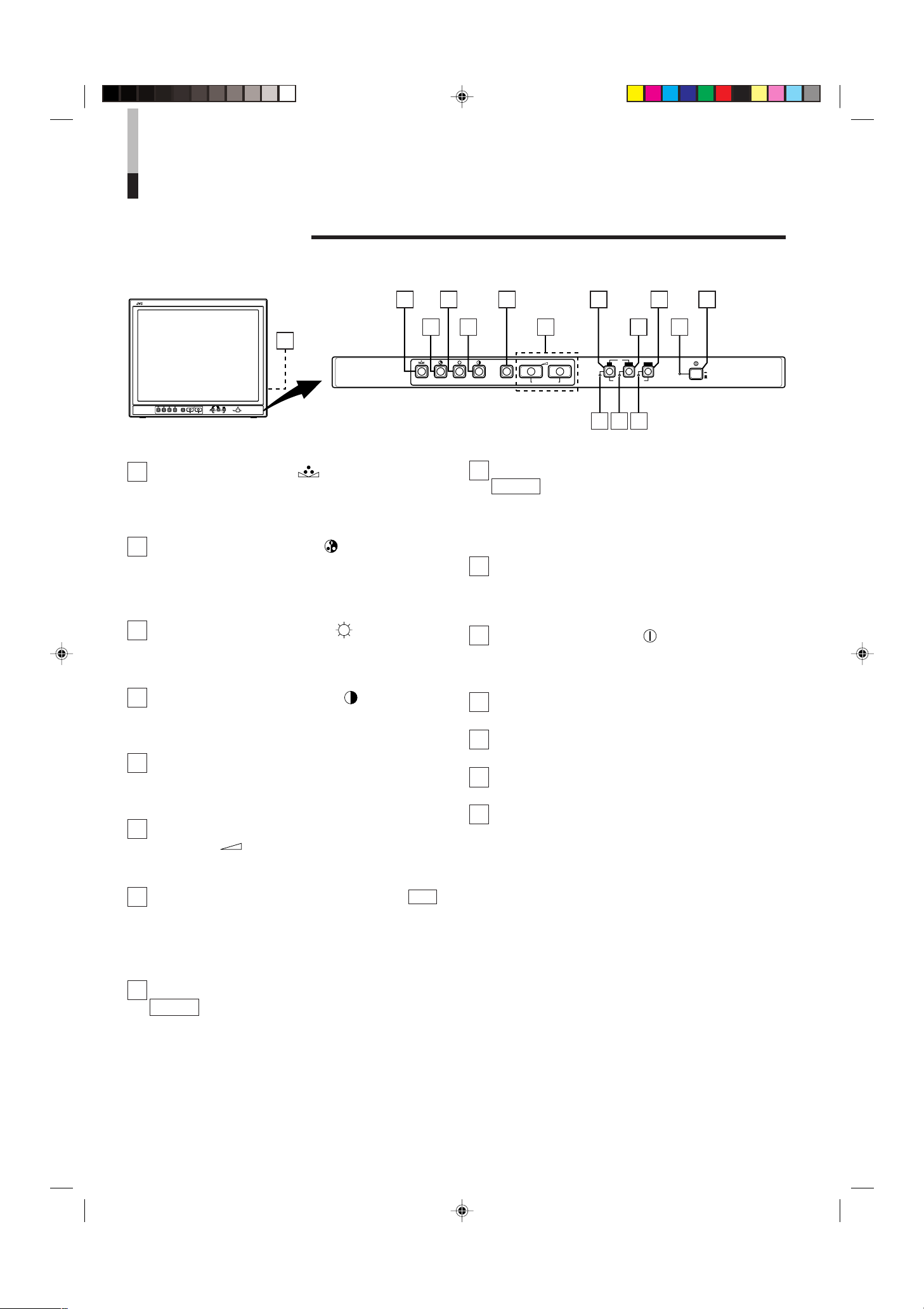
CONTROLS AND FEATURES
TM-2100PN
PHASE CHROMA BRIGHT
CONTRAST
MENU
INPUT SELECT
VOLUME/SELECT
– +
BA
POWER
ON
OFF
Y/ C VIDEO VIDEO
15
FRONT VIEW
<Front Panel>
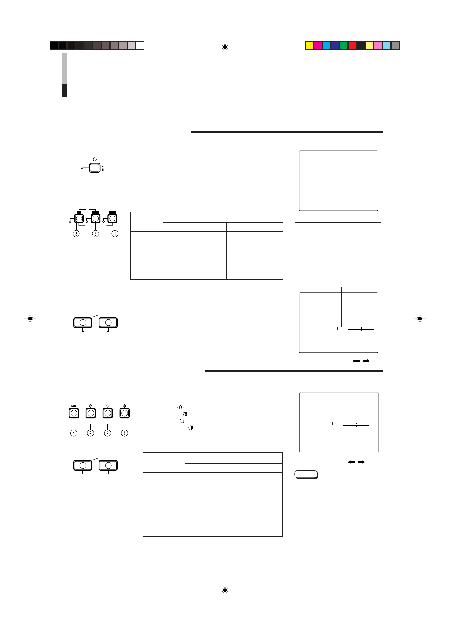
1 Phase button [PHASE ]
Press this button to set the picture hue adjustment mode.
Adjust the value with the VOLUME/SELECT buttons. Also
used as a control button in the menu function mode.
2 Chroma button [CHROMA ]
Press this button to set the picture colour density adjustment mode. Adjust the value with the VOLUME/SELECT
buttons. Also used as a control button in the menu
function mode.
3 Brightness button [BRIGHT ]
Press this button to adjust picture brightness. Adjust the
value with the VOLUME/SELECT buttons. Also used as a
control button in the menu function mode.
4 Contrast button [CONTRAST ]
Press this button to adjust picture contrast. Adjust the
value with the VOLUME/SELECT buttons. Also used as a
control button in the menu function mode.
5 Menu button [MENU]
Displays and exits the <MENU> screen.
Pressing the PHASE button with the Menu button
depressed will display the <SET-UP MENU> screen.
6 Volume/Select buttons [VOLUME/
SELECT – +]
Adjusts the speaker volume. Also used as a control button
in the menu function mode.
9 Input A (VIDEO) button [INPUT SELECT A
VIDEO ]
Selects the video signal input to the VIDEO A terminal
(BNC connector) and the audio signal input to the AUDIO
A terminal (RCA connector) on the rear panel. When
selected, the input A (VIDEO) indicator
$ lights.
10 Power indicator
Lights in green when the power is ON.
Lit : When the power is on.
Unlit : When the power is off.
11 Power switch [POWER ]
Press this switch to turn the power on or off.
_ ON : Power is turned on.
— OFF : Power is turned off.
12 Input B (Y/C) indicator
Lights in green when the Input B (Y/C) is selected.
13 Input B (VIDEO) indicator
Lights in green when the Input B (VIDEO) is selected.
14 Input A (VIDEO) indicator
Lights in green when the Input A (VIDEO) is selected.
15 Speaker
A built-in speaker is located inside the right side panel
when the monitor is viewed from the front.
7 Input B (Y/C) button [INPUT SELECT B Y/C ]
Selects the video signal input to the VIDEO B (Y/C)
terminal (mini DIN 4 pin connector) and the audio signal
input to the AUDIO B terminal (RCA connector) on the
rear panel. When selected, the input B (Y/C) indicator
lights.
8 Input B (VIDEO) button [INPUT SELECT B
VIDEO ]
Selects the video signal input to the VIDEO B terminal
(BNC connector) and the audio signal input to the AUDIO
B terminal (RCA connector) on the rear panel. When
selected, the input B (VIDEO) indicator
4
LCT0053-002A-H (EN) 02.07.30, 2:45 PM4
# lights.
@
Page 7
OUTIN
A
B
VIDEO
A
B
AUDIO
REMOTE
OUTIN
OUT
IN
OUT
IN
IN
OUT
Y/ C
OUT
IN
22
23
OUTIN
A
B
VIDEO
A
B
AUDIO
REMOTE
OUTIN
OUT
IN
OUT
IN
IN
OUT
Y/ C
OUT
IN
16
17
18
19
20
21
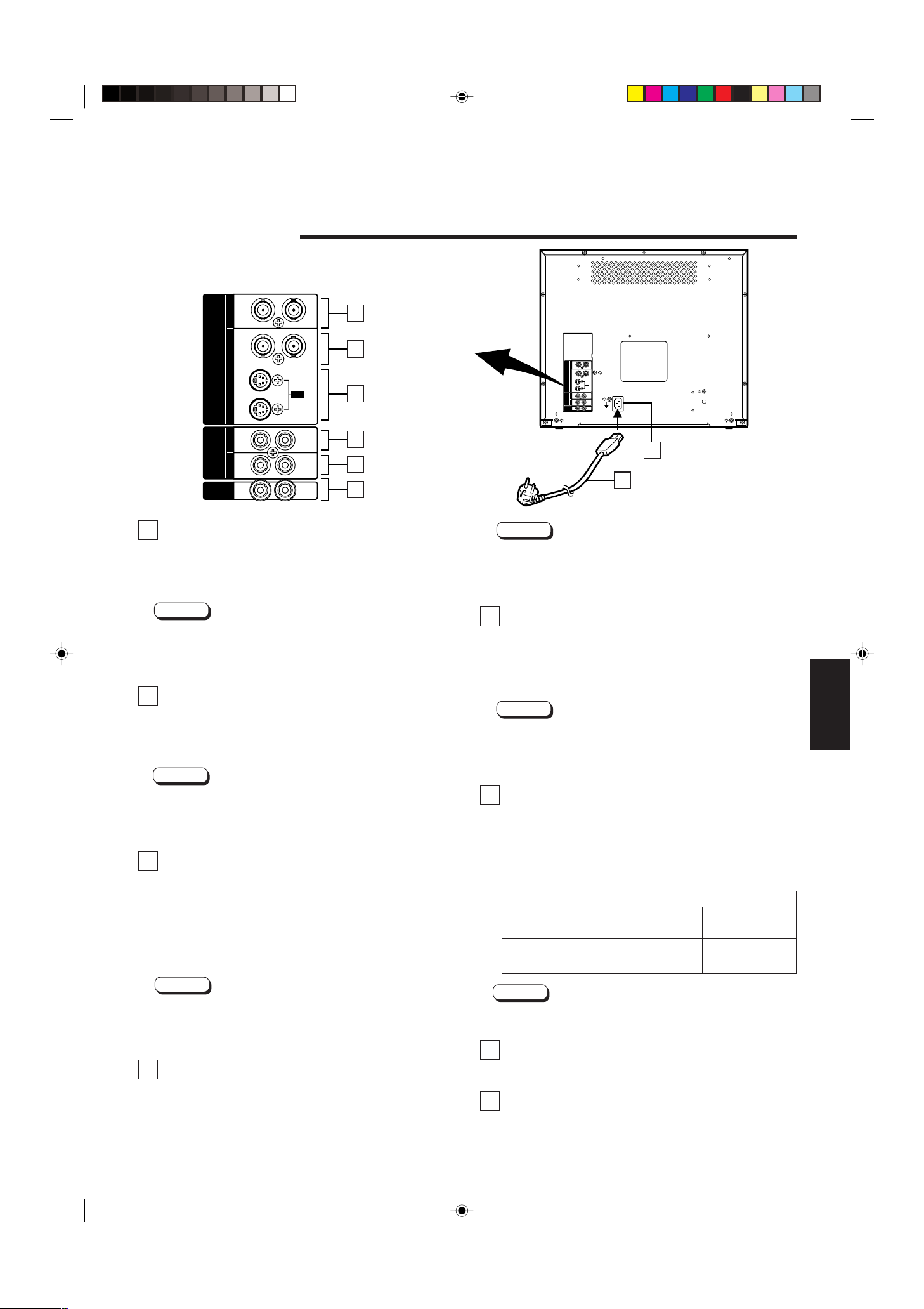
REAR VIEW
<Rear Panel>
To AC outlet
(230 V AC, 50 Hz/60 Hz)
16 Video A terminals [VIDEO A IN/OUT]
Video signal input (IN) and output (OUT) terminals.
The output terminal is bridge-connected.
IN : Video signal input terminal
OUT : Bridge-connected video signal output terminal
Notes:
* For corresponding audio signals, use the AUDIO A
terminals
* Also refer to the BASIC CONNECTION EXAMPLE on
pages 11 and 12.
(.
17 Video B terminals [VIDEO B IN/OUT]
Video signal input (IN) and output (OUT) terminals.
The output terminal is bridge-connected.
IN : Video signal input terminal
OUT : Bridge-connected video signal output terminal
Notes:
* For corresponding audio signals, use the AUDIO B
terminals
* Also refer to the BASIC CONNECTION EXAMPLE on
pages 11 and 12.
).
18 Video B (Y/C) terminals [VIDEO B Y/C IN/
OUT]
Y/C (S-Video) signal input (IN) and output (OUT) terminals.
The output terminal is bridge-connected.
IN : Y/C-separated (S-video) signal input terminal
OUT : Bridge-connected Y/C-separated (S-video) signal
output terminal
Notes:
* For corresponding audio signals, use the AUDIO B
terminals
* Also refer to the BASIC CONNECTION EXAMPLE on
pages 11 and 12.
).
19 Audio A terminal [AUDIO A IN/OUT]
Input (IN) and output (OUT) terminals for the audio signal
corresponding the VIDEO A terminals
LCT0053-002A-H (EN) 02.07.30, 2:45 PM5
terminal is bridge-connected.
IN : Audio signal input terminal
OUT : Bridge-connected audio signal output terminal
^. The output
Notes:
* For corresponding video signals, use the VIDEO A
terminal
^.
* Also refer to the BASIC CONNECTION EXAMPLE on
pages 11 and 12.
20 Audio B terminals [AUDIO B IN/OUT]
Input (IN) and output (OUT) terminals for the audio signals
corresponding to the VIDEO B terminals
C) terminals
*. The output terminal is bridge-connected.
& or VIDEO B (Y/
IN : Audio signal input terminal
OUT : Bridge-connected audio signal output terminal
Notes:
* For corresponding video signals, use the VIDEO B
terminals
* Also refer to the BASIC CONNECTION EXAMPLE on
pages 11 and 12.
& or VIDEO B (Y/C) terminals *.
21 Remote terminals [REMOTE IN/OUT]
Input (IN) and output (OUT) terminals for external control.
The output terminal is bridge-connected. External control
is available either to select the ASPECT RATIO or to
select ON or OFF in BRIGHTNESS P.S. function mode.
Set the external control in the <SET-UP MENU> screen
mode.
External control
functions
External control switch
Open circuit Short circuit
(open) (short)
ASPECT RATIO 4–3 (4:3) 16–9 (16:9)
BRIGHTNESS P.S. OFF ON
Note:
* Also refer to the BASIC CONNECTION EXAMPLE on
pages 11 and 12.
22 AC Inlet [AC IN]
Power input connector. Connect the provided AC power
cord
e to an AC outlet (230 V AC, 50 Hz/60 Hz).
23 Power cord
Connects the provided power cord (230 V AC, 50 Hz/
60 Hz) to the AC IN connector.
ENGLISH
5
Page 8
PHASE CHROMA BRIGHT CONTRAST
INPUT SELECT
B
A
Y/ C VIDEO VIDEO
+
–
HOW TO HANDLE BASIC
POWER
ON
OFF
VOLUME/SELECT
– +
+
–
VOLUME/SELECT
– +
OPERATIONS
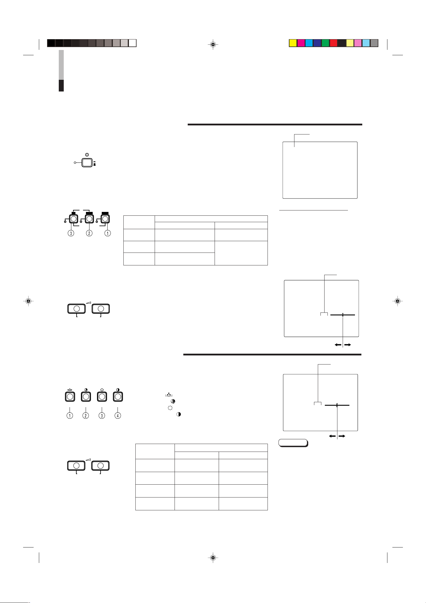
BASIC OPERATION
1. Press the POWER switch to turn on the power.
_ON : Power turns ON. (Power indicator: lit)
—OFF : Power turns OFF. (Power indicator: unlit)
2. Press the INPUT SELECT button to choose input.
Selects video/audio signals input to terminals on the rear
panel.
INPUT
SELECT
button
1 Input A
(VIDEO)
2 Input B
(VIDEO)
3 Input B
(Y/C)
3. Press the VOLUME/SELECT buttons to adjust the
speaker volume.
Press this button to display the speaker volume level on the
screen.
+ : The Built-in speaker volume is increased. (00 = 50)
– : The Built-in speaker volume is decreased. (50 = 00)
* Screen indication will disappear about 10 seconds after
operating.
Terminals on the rear panel
Video signal input Audio signal input
VIDEO A terminal AUDIO A terminal
VIDEO B terminal
AUDIO B terminal
VIDEO B (Y/C) terminal
Colour system indication
(PAL or NTSC)
PAL
With regard to Colour system indication
● With the COLOR SYSTEM setting set
to AUTO mode, when you turn on the
power or select inputs, the colour
system indication appears for about 3
seconds on the screen while PAL or
NTSC signals are being detected.
It does not appear when receiving B/
W signal or when no signal is input.
See page 7 for COLOR SYSTEM
setting.
VOLUME : 20
00 ~ 50
PICTURE ADJUSTMENT
1. Press select button corresponding to the item you
want to adjust.
2. Adjust with the VOLUME/SELECT buttons.
The item you select is displayed on the screen.
1 PHASE ( ) : Phase control
2 CHROMA ( ) : Chroma control
3 BRIGHT ( ) : Brightness control
4 CONTRAST ( ) : Contrast control
VOLUME/SELECT button
Items
PHASE
(Phase)
CHROMA
(Chroma)
BRIGHT
(Brightness)
CONTRAST
(Contrast)
* Screen indication will disappear about 10 seconds
after operating.
– +
reddish greenish
lighter deeper
darker brighter
lower higher
–20 ~ +20
PHASE : 00
Notes:
● Phase control is effective only in the
NTSC colour system mode.
● Chroma control is not effective when
receiving B/W or when no signal is
input.
● When the Chroma control is set to
level “ –20”, the picture turns
monochrome.
● “NO EFFECT” is displayed (For about
3 seconds) when your selected
function has no effect.
6
LCT0053-002A-H (EN) 02.07.30, 2:45 PM6
Page 9

PHASE CHROMA BRIGHT CONTRAST MENU VOLUME/SELECT
– +
EXIT
6500 9300
AUTO NTSC AUTO PAL
4 – 3 16 – 9
OFF ON
00 +1 +2 +3 +4 +5
HOW TO USE THE MENU FUNCTIONS
MENU
PHASE CHROMA
SHARPNESS
COLOR TEMP.
COLOR SYSTEM
ASPECT RATIO
BRIGHTNESS P.S.
VOLUME/SELECT
– +
MENU
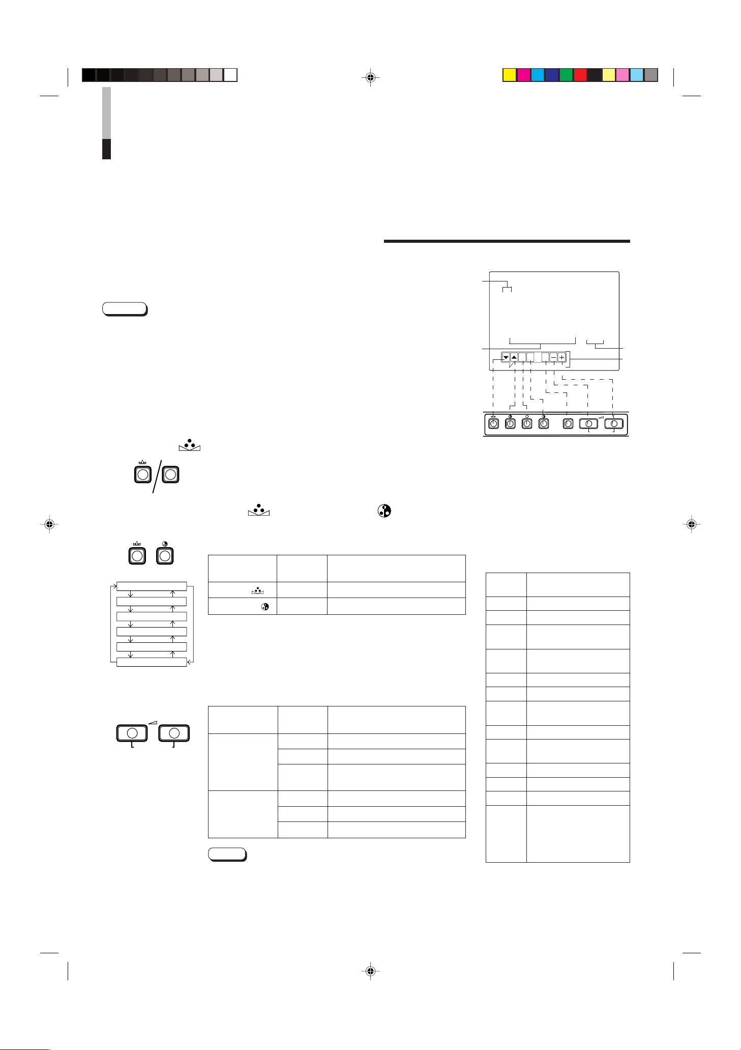
DISPLAY AND SELECTION IN THE <MENU>
SCREEN MODE (SETTING)
You can set the following menu items.
Set them depending on your needs.
• SHARPNESS • ASPECT RATIO
• COLOR TEMP. • BRIGHTNESS P.S.
• COLOR SYSTEM
1. Press the MENU button.
The <MENU> screen is displayed.
2. Press the PHASE ( ) or CHROMA ( ) button
to select MENU items.
A selection mark (3) is put next to the selected item.
<MENU> screen
1
< MENU >
‰ SHARPNESS : 00
COLOR TEMP. : 6500
COLOR SYSTEM : AUTO
ASPECT RATIO : 4–3
BRIGHTNESS P.S. : OFF
2
3
4
Front panel Function
button displayed
Contents
PHASE ( ) ▼ Forwards selection mark (3)
CHROMA (
) 5 Reverses selection mark (3)
3. Press the VOLUME/SELECT buttons to set.
Front panel Function
button displayed
VOLUME/
SELECT (+)
VOLUME/
SELECT (–)
+ Increases (to max. value)
3 Forwards the setting value
– Decreases (to min. value)
2 Reverses the setting value
Menu items Purpose Setting range
SHARPNESS Picture sharpness
COLOR TEMP.
COLOR
SYSTEM
Colour temperature of
white balance
Colour system
ASPECT RATIO Aspect ratio
BRIGHTNESS Brightness Peak
P.S. Suppressor function
* Normally set the COLOR SYSTEM to the AUTO mode. If reception in the AUTO mode is not good,
set it to the exclusive mode (NTSC or PAL) corresponding to the received colour system.
Contents
4. If you want to set the other menu items, repeat
procedures 2 and 3.
5. Press the MENU button to quit.
Front panel Function
button displayed
MENU EXIT
Quits (or Releases) the
<MENU> screen
Contents
<Front panel button>
1 Selection mark (3): Indicates the
menu item you select.
2 Menu item: Menu items you can
select.
3 Setting display: Indicates the current
settings (value).
4 Function display: The functions of
the front panel buttons (7 buttons on
the left.) correspond to the function
displayed.
Function
displayed
▼ Forwards the menu item
5 Reverses the menu item
– Lowers the adjustment
+ Raises the adjustment
3 Forwards the setting value
2 Reverses the setting value
EXIT Exits the <MENU> screen
Notes:
● BRIGHTNESS P.S. (or B.P.S.) stands
for Brightness Peak Suppressor. This
function is used to suppress (cut) the
white peak portion of the picture, so as
to reduce the picture’s burning on the
screen (cathode ray tube).
● When the BRIGHTNESS P.S. (or B.P.S.)
function is ON, the suppressed white
peak portion (for example, the lit part of
a fluorescent lamp) seems to be blurred.
If required, lower the setting for the
B.P.S. LEVEL in the <SET- UP MENU>
screen mode, or turn off the BRIGHTNESS P.S. function.
● When the screen aspect ratio is set to
16-9 (16:9) the picture will be vertically
reduced.
● If REMOTE is displayed in the ASPECT
RATIO or BRIGHTNESS P.S. setting
values in the <MENU> screen, REMOTE
SELECT is set to “ASPT” or “B.P.S.” in the
<SET-UP MENU> screen. In this case, it
is not possible to adjust the setting ranges
for ASPECT RATIO and BRIGHTNESS
P.S. If you need to make adjustments, use
the external control function or turn off the
REMOTE SELECT setting.
Contens
value (to the minimum)
value (to the maximum)
ENGLISH
LCT0053-002A-H (EN) 02.07.30, 2:46 PM7
7
Page 10
PHASE CHROMA BRIGHT CONTRAST MENU VOLUME/SELECT
– +
EXIT
HOW TO USE THE MENU
MENUPHASE
H. POSITION
V. POSITION
WHITE BALANCE
CONTROL LOCK
B.P.S. LEVEL
REMOTE SELECT
VOLUME/SELECT
– +
PHASE CHROMA
FUNCTIONS
(cont’d)
DISPLAY AND SELECTIONS IN THE <SET-UP
MENU> MODE (SETTING)
You can set the following set-up menu items.
• H. POSITION • WHITE BALANCE • B.P.S. LEVEL
• V. POSITION • CONTROL LOCK • REMOTE SELECT
Notes:
● Parameters for H. POSITION and V. POSITION can be set separately depending on the
video input (Input A (VIDEO), Input B (VIDEO) or Input B (Y/C)) selected by the input
select buttons on the front panel.
Select the required video input with the input select buttons on the front panel in
advance.
● WHITE BALANCE can be set individually at 6500 or 9300 for the colour temperature
value.
Set COLOR TEMP. to the value 6500 or 9300 in the <MENU> screen in advance.
1. While pressing the MENU button, press the
PHASE (
) button.
The <SET-UP MENU> screen is displayed.
2. Press the PHASE ( ) or CHROMA ( ) button
to select the desired menu item.
A selection mark (3) is put next to the selected item.
Front panel Function
button displayed
PHASE ( ) ▼ Forwards selection mark (3)
CHROMA ( ) 5 Reverses selection mark (3)
Contents
3. Press the VOLUME/SELECT buttons to set.
Front panel Function
button displayed
+ Increases (to max. value)
VOLUME/
SELECT (+)
VOLUME/
SELECT (–)
3 Forwards the setting value
CUTO Selects CUT OFF setting
screen
– Decreases (to min. value)
2 Reverses the setting value
DRV Selects DRIVE setting screen
Note:
Contents
<SET-UP MENU> screen
1
<SET–UP MENU>
‰ H. POSITION : 00
V. POSITION : 00
WHITE BALANCE
CONTROL LOCK : OFF
B. P. S. LEVEL : 10
REMOTE SELECT : OFF
2
<Front panel button>
1 Selection mark (3): Indicates the
menu item you select.
2 Menu item: Menu items you can
select.
3 Setting display: Indicates the current
settings (value).
4 Function display: The functions of
the front panel buttons (7 buttons on
the left.) correspond to the function
displayed.
Function
displayed
▼ Forwards the menu item
5 Reverses the menu item
– Lowers the adjustment
+ Raises the adjustment
3 Forwards the setting value
2 Reverses the setting value
EXIT
DRV Selects DRV adjustment
CUTO
R Adjusts red signal level
G Adjusts green signal level
B Adjusts blue signal level
DISP
Contens
value (to the minimum)
value (to the maximum)
Exits the <SET-UP MENU>
screen (release)
Selects CUT OFF
adjustment
Turns the ON-SCREEN
display on or off. (This
function is effective only in
the DRIVE or CUT OFF
adjustment mode.)
3
4
8
LCT0053-002A-H (EN) 02.07.30, 2:46 PM8
● For the WHITE BALANCE setting, select the CUT OFF or
DRIVE setting screen, then select the buttons (PHASE/
CHROMA/BRIGHT) corresponding to the function indicated
(R/G/B).
Page 11
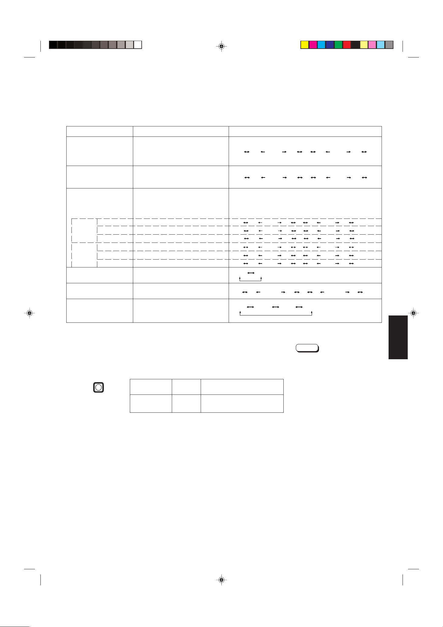
Set-up menu items Purpose Settings
–09 –08 • • • • • • –01 00 +01 • • • • • • +08 +09
–09 –08 • • • • • • –01 00 +01 • • • • • • +08 +09
–09 –08 • • • • • • –01 00 +01 • • • • • • +08 +09
–09 –08 • • • • • • –01 00 +01 • • • • • • +08 +09
–09 –08 • • • • • • –01 00 +01 • • • • • • +08 +09
–09 –08 • • • • • • –01 00 +01 • • • • • • +08 +09
–09 –08 • • • • • • –01 00 +01 • • • • • • +08 +09
–09 –08 • • • • • • –01 00 +01 • • • • • • +08 +09
OFF ON
00 01 • • • • • • • 09 10 11 • • • • • • • 19 20
OFF ASPT OFF B.P.S.
MENU
H. POSITION Adjusts the horizontal position of
the screen (+ : Horizontal position
shifts to the right/–: Horizontal
position shifts to the left)
V. POSITION Adjusts the vertical position on the
screen (+: Vertical position moves
down/–: Vertical position moves up)
WHITE BALANCE Adjusts the white balance Selects DRIVE (DRV) or CUT OFF (CUTO) adjustment.
Screen setting is changed to the selected setting mode.
Select R/G/B buttons corresponding to the function display
to adjust.
DRIVE R.DRIVE Adjusts red level
G.DRIVE Adjusts green level
B.DRIVE Adjusts blue level
CUT OFF R. CUT OFF Adjusts red cut off
G. CUT OFF Adjusts green cut off
B. CUT OFF Adjusts blue cut off
CONTROL LOCK Sets the operation buttons on the
front panel to control lock mode
B. P. S. LEVEL Sets the level for Brightness Peak
Suppressor function
REMOTE SELECT Sets the external control function
(ASPECT RATIO or BRIGHTNESS
P.S.)
* ASPT : ASPECT RATIO
B.P.S.: BRIGHTNESS P.S.
4. To set the other set-up menu items, repeat the
procedures 2 and 3.
5. Press the MENU button to quit.
Front panel Function
button displayed
MENU EXIT
Quits (or Releases) the
<MENU> screen
Contents
Notes:
● When the CONTROL LOCK function
is set to ON, pressing operation
buttons on the front panel will display
the message “CONTROL LOCK ON!”
on the screen for about 3 seconds.
● The CONTROL LOCK function is
maintained even when the power is
turned off.
● To turn off the CONTROL LOCK
function, while holding the MENU
button press the PHASE button. Then
set the CONTROL LOCK function to
OFF.
● Even when the CONTROL LOCK
function is set to ON, the following
operations are available:
– Power Switch operation.
– Sound volume adjustment with the
VOLUME/SELECT button.
– Display or exit of the <SET-UP
MENU> screen.
– External control of ASPECT RATIO
or BRIGHTNESS P.S. when
REMOTE SELECT is set to ON .
ENGLISH
LCT0053-002A-H (EN) 02.07.30, 2:46 PM9
9
Page 12
HOW TO INITIALISE THE
PHASE MENU
POWER
_ON
—OFF
CONTRAST
VOLUME/SELECT
– +
POWER
ON
OFF
SETTING
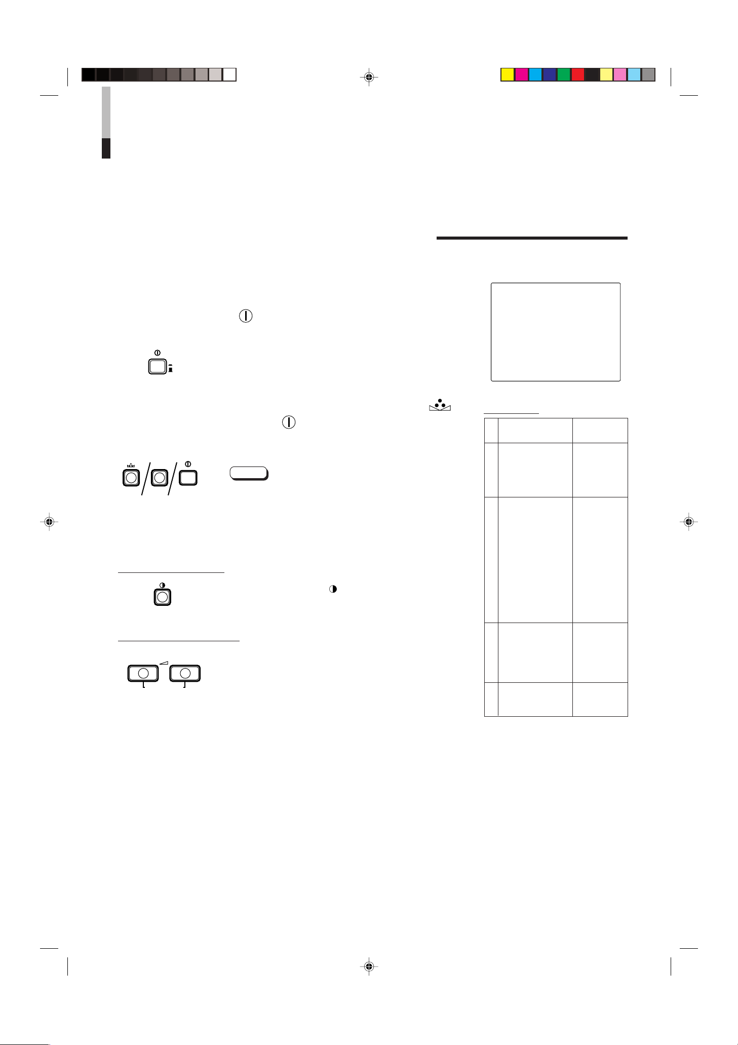
SCREEN DISPLAY AND SELECTIONS IN THE
<SET-UP MENU> RESET MODE
You can set <MENU> and <SET-UP MENU> screen items, picture adjustment items and
the volume level to their factory-set (initial) values.
1. Press the Power ( ) Switch to turn the power
OFF (
—
).
2. While pressing both MENU button and PHASE ( )
button, press the Power ( ) switch to turn the power
_
ON (
).
The <SET-UP MENU> RESET screen is displayed.
Note:
● The <SET-UP MENU> PRESET screen will not be
displayed if the MENU or PHASE buttons are pressed
for a very short time. Keep pressing them until the
display screen appears.
3. Setting
Initialisation is required.
Press the CONTRAST (
* Initialisation is completed, and the <SET-UP MENU>
RESET screen disappears.
) button.
<SET-UP MENU> RESET screen
<SET–UP MENU> RESET
Are you sure ?
“Yes ” then <CONTRAST>
“No” then <+> or <–>
Initial settings
Functions (Items)
Sorts
SHARPNESS 00
COLOR TEMP. 6500
COLOR SYSTEM
ASPECT RATIO 4–3
BRIGHTNESS P.S. OFF
<MENU> screen
H. POSITION 00
V. POSITION 00
WHITE BALANCE
R. CUT OFF 00
G. CUT OFF 00
B. CUT OFF 00
R. DRIVE 00
G. DRIVE 00
B. DRIVE 00
CONTROL LOCK OFF
<SET-UP MENU> screen
B.P.S. LEVEL 10
REMOTE SELECT OFF
Initialisation
(setting)
AUTO
10
Initialisation is not required.
Press the VOLUME/SELECT [+] or [–] button.
* Initialisation is aborted, and the <SET-UP MENU>
RESET screen disappears.
PHASE 00
CHROMA 00
CONTRAST 00
BRIGHT 00
Picture adjustment
VOLUME 20
Volume
LCT0053-002A-H (EN) 02.07.30, 2:46 PM10
Page 13

Video Monitor
TM-2100PN
<second one>
VCR
REMOTE
(Remote cable)
VCR
Video Monitor
Video Camera
(Audio signal cable)
Audio
Video
(Video signal cable)
: Signal Flow
Audio
Video
(Video signal cable)
(Audio signal cable)
REMOTE
(Remote cable)
OUTIN
A
B
VIDEO
A
B
AUDIO
REMOTE
OUTIN
OUT
IN
OUT
IN
IN
OUT
Y/ C
OUT
IN
TM-2100PN
PHASECHROMA BRIGHT CONTRAST MENU
INPUT SELECT
VOLUME/SELECT
– +
BA
POWER
_ON
—OFF
Y/ C VIDEO VIDEO
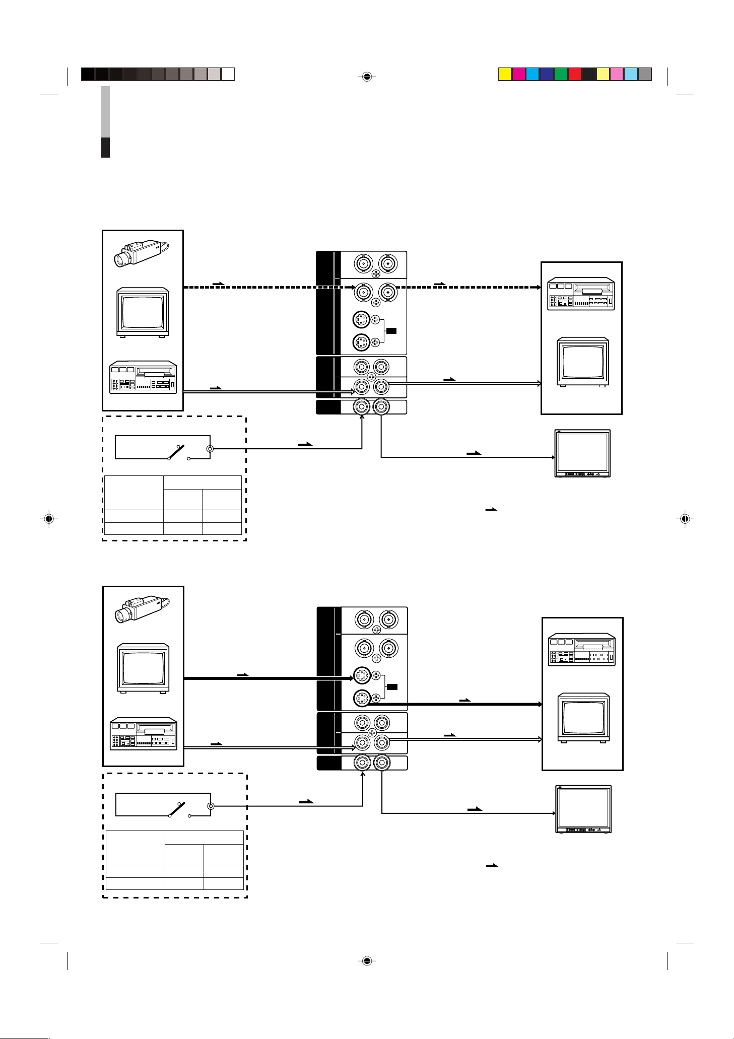
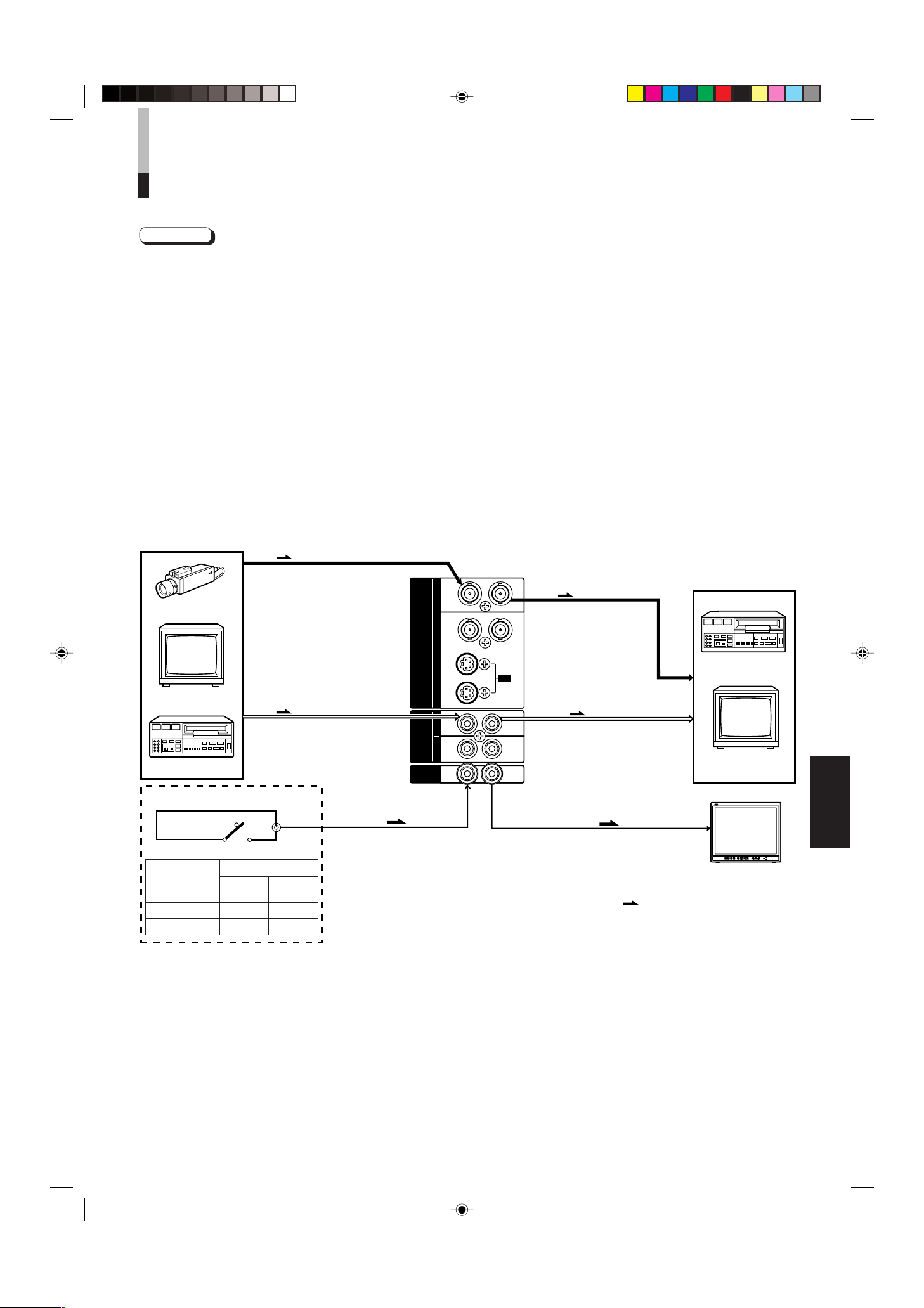
BASIC CONNECTION EXAMPLE
Notes:
• Before connecting your system, make sure that all units are turned off.
• The illustration below shows some examples of different connections. Terminal connections may differ depending on the
component connected. Be sure to refer to the instructions provided with the unit(s) you are connecting.
• Each pair of input (IN) and output (OUT) terminals are bridge-connected.
• If you’re not connecting any equipment to a bridged output (OUT) terminal, be sure not to connect any other cables to the
bridged output (OUT) terminal as this will cause the terminating resistance switch to open (auto terminate function).
• When making a bridge connection, connect the input (IN) and output (OUT) terminals on the monitor to separate video
components.
(For example, if both terminals are connected to the same VCR, resonance may occur except during playback. This is caused by
the same video signal “looping” between the VCRs, and is not a malfunction.)
• Select the video input (Input A (VIDEO), Input B (Y/C) or Input B (VIDEO)) with the INPUT SELECT button on the front panel.
• The ASPECT RATIO or BRIGHTNESS P.S. function can be controlled via the REMOTE terminal. To do this, set REMOTE
SELECT in the <SET-UP MENU> mode. (Refer to pages 8 and 9.)
VIDEO A Connection Example
(Select Input A (VIDEO) button)
External control switch
open circuit (open)
External control switch
External control
functions
ASPECT RATIO 4–3 (4:3) 16–9 (16:9)
BRIGHTNESS P.S.
Open circuit Short circuit
short circuit (short)
RCA pin
(open) (short)
OFF ON
ENGLISH
LCT0053-002A-H (EN) 02.07.30, 2:46 PM11
11
Page 14
Video Monitor
TM-2100PN
<second one>
VCR
VCR
Video Monitor
Video Camera
(Audio signal cable)
Audio
: Signal Flow
Audio
(Audio signal cable)
REMOTE
(Remote cable)
OUTIN
A
B
VIDEO
A
B
AUDIO
REMOTE
OUTIN
OUT
IN
OUT
IN
IN
OUT
Y/ C
OUT
IN
Y/C (S-video)
(Y/C (S-video) signal cable)
Y/C (S-video)
(Y/C (S-video) signal cable)
REMOTE
(Remote cable)
TM-2100PN
PHASECHROMA BRIGHT CONTRAST MENU
INPUT SELECT
VOLUME/SELECT
– +
BA
POWER
_ON
—OFF
Y/ C VIDEO VIDEO
Video Monitor
TM-2100PN
<second one>
VCR
VCR
Video Monitor
Video Camera
(Audio signal cable)
Audio
: Signal Flow
Audio
Video
(Video signal cable)
(Audio signal cable)
REMOTE
(Remote cable)
OUTIN
A
B
VIDEO
A
B
AUDIO
REMOTE
OUTIN
OUT
IN
OUT
IN
IN
OUT
Y/ C
OUT
IN
Video
(Video signal cable)
REMOTE
(Remote cable)
TM-2100PN
PHASECHROMA BRIGHT CONTRAST MENU
INPUT SELECT
VOLUME/SELECT
– +
BA
POWER
_ON
—OFF
Y/ C VIDEO VIDEO
BASIC CONNECTION EXAMPLE
(cont’d)
VIDEO B (VIDEO) Connection Example
(Select Input B (VIDEO) button)
External control switch
open circuit (open)
RCA pin
short circuit (short)
External control switch
External control
functions
Open circuit Short circuit
(open) (short)
ASPECT RATIO 4–3 (4:3) 16–9 (16:9)
BRIGHTNESS P.S.
OFF ON
VIDEO B (Y/C) Connection Example
(Select Input B (Y/C) button)
External control switch
open circuit (open)
short circuit (short)
External control switch
External control
functions
Open circuit Short circuit
(open) (short)
ASPECT RATIO 4–3 (4:3) 16–9 (16:9)
BRIGHTNESS P.S.
OFF ON
RCA pin
12
LCT0053-002A-H (EN) 02.07.30, 2:46 PM12
Page 15

TROUBLESHOOTING
Solutions to common problems related to your monitor are described here. If none of the solutions presented here
solves the problem, unplug the monitor and consult a JVC-authorised dealer or service centre for assistance.
Problems
No power supply.
No picture with the
power on.
No sound.
Shaking picture.
No colours, wrong
colour, or dark picture.
Unnatural, irregularly
coloured, or distorted
picture.
Dark stripes appear
at the top and bottom
of the screen, picture
vertically squeezed.
White peak portion of
the picture (for
example, the lit part
of a fluorescent lamp)
is dark, unclear, and
the colour is blurred.
Front panel button
does not function.
Points to be checked
Is the power plug loosened or disconnected?
Is the video signal output from the connected
component?
Is the input signal selected properly?
Is the video cable disconnected?
Is the audio signal output from the connected
component?
Is the volume output set to minimum?
Is the audio cable disconnected?
Is the monitor close to a device generating a
strong magnetic field?
Is the colour system selected properly?
Has the picture control setting (CONTRAST,
BRIGHT, CHROMA or PHASE) been changed?
Is the monitor close to a speaker, magnet or any
other device generating a strong magnetic field?
Is the aspect ratio set to 16:9?
Is the BRIGHTNESS P.S. function set to ON?
Are the operation buttons on the front panel
locked? ( Has CONTROL LOCK function set to
ON?)
Measures (Remedy)
Firmly insert the power plug.
Set the connected component correctly.
Select the required video signal input with the
Input select button. (See page 6.)
Connect the video signal cable firmly.
(See pages 11 and 12.)
Set the connected component correctly.
Adjust the speaker volume with the VOLUME/
SELECT buttons. (See page 6.)
Connect the audio signal cable firmly.
(See pages 11 and 12.)
Move the device away from the monitor until the
picture stabilises.
Set the COLOR SYSTEM in the <MENU> screen
mode to [AUTO] mode. (See page 7.)
Set each picture control to the standard setting.
(See page 6.)
Move the device away from the monitor and turn
the monitor’s power off. Wait at least 30 minutes,
then turn the power on again.
Set the ASPECT RATIO in the <MENU> screen
mode to [4 : 3 (4 - 3)] (See page 7.)
When controlling externally, ASPECT RATIO
should be set to [4 : 3 (4-3)].
(See pages 11 and 12.)
Set the BRIGHTNESS P.S. function in the
<MENU> screen mode to OFF. (See page 7.)
When controlling externally, BRIGHTNESS P.S.
function should be set to OFF.
(See pages 11 and 12.)
Set the CONTROL LOCK to OFF in the <SETUP MENU> screen mode. (See pages 8 and 9.)
ENGLISH
The following are not malfunctions:
● When a bright still image (such as a white cloth) is displayed for a long period, it may appear to be coloured. This is due to the
structure of the cathode ray tube and will be deleted when another image is displayed.
● You experience a mild electric shock when you touch the picture tube. This phenomenon is due to a normal buildup of static
electricity on the CRT and is not harmful.
● The monitor emits a strange sound when the room temperature changes suddenly. This is only a problem if an abnormality
appears on the screen as well.
LCT0053-002A-H (EN) 02.07.30, 2:46 PM13
13
Page 16
SPECIFICATIONS
MODEL TM-2100PN
Type Colour video monitor
Colour system PAL, NTSC (3.58)
Picture tube 54 cm measured diagonally,
flat-square type,
90° deflection, in-line gun,
vertical line trio type
(phosphor stripe pitch 0.69 mm)
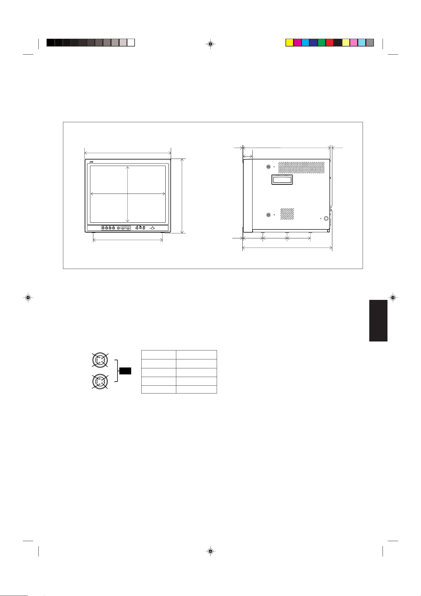
Effective screen size Width 406.4 mm
Height 304.8 mm
Diagonal 508 mm
Scanning frequency H : 15.734 kHz (NTSC), 15.625 kHz (PAL)
V : 59.94 Hz (NTSC), 50 Hz (PAL)
Horizontal resolution 450 TV lines or more
(Y/C input mode)
Input terminals VIDEO A Composite video: 1 line, BNC connector x 2,
1 V(p-p), 75 Ω negative sync
(bridge connection possible, auto termination)
VIDEO B Composite video: 1 line, BNC connector x 2,
1 V(p-p), 75 Ω negative sync
(bridge connection possible, auto termination)
Y/C-separated: 1 line, mini-DIN 4-pin connector x 2
Y: 1.0 V(p-p), 75 Ω
C: 0.286 V(p-p), 75 Ω (NTSC), 0.3 V(p-p), 75 Ω (PAL)
(bridge connection possible, auto termination)
AUDIO A 1 line (monaural), RCA pin x 2, 0.5 V(rms), high-impedance
(bridge connection possible)
AUDIO B 1 line (monaural), RCA pin x 2, 0.5 V(rms), high-impedance
(bridge connection possible)
REMOTE 1 line, RCA pin x 2 (bridge connection possible)
Audio power output 1 W (monaural)
Built-in speaker 8 cm round x 1, impedance of 8 Ω
Environmental conditions Operation temperature: 0 – 40 °C
Operation humidity: 20 – 80% (non-condensing)
Power requirements 230 V AC, 50 Hz/ 60 Hz
Power consumption 0.72A (230 V AC)
Dimensions Width 476 mm
Height 407.5 mm
Depth 492 mm
Weight 28.5 kg
Accessory AC power cord (2 m) x 1
* Illustrations used in this manual are for explanatory purposes only. The appearance of the actual product may differ slightly.
* Dimensions and weight are approximate.
* E. & O. E. Design and specifications subject to change without notice.
14
LCT0053-002A-H (EN) 02.07.30, 2:46 PM14
Page 17
4
2
3
4
3
1
2
1
OUT
IN
Y/C
4791.3 9.5
105
492
135 128.5
50.2
3.5
416.4
*
476
382.8
314.8
*
407.5
TM-2100PN
PHASE CHROMA BRIGHT
CONTRAST
MENU
INPUT SELECT
VOLUME/SELECT
– +
BA
POWER
ON
OFF
Y/ C VIDEO VIDEO
Dimensions
Unit : mm
< Front View >
* Asterisks (*) are used to indicate front panel
dimensions.
< Side View >
Y/C (Mini DIN 4 pin) terminal
specification
Pin No. Signal
1 GND (Y)
2 GND (C)
3Y
4C
ENGLISH
LCT0053-002A-H (EN) 02.07.30, 2:46 PM15
15
Page 18

ï /ï /îí 02.07.30, 3:23 PM4
Page 19

BEDIENUNGSANLEITUNG
FARB-VIDEO-MONITOR
TM-2100PN
LCT0053-002A-H (GE) 02.07.30, 2:47 PM1
DEUTSCH
1
Page 20

Vielen Dank für den Kauf dieses Farb-Monitors von JVC. Bitte lesen Sie diese
Bedienungsanleitung vor Ingebrauchnahme sorgfältig durch, um einen einwandfreien
Betrieb sicherzustellen.
SICHERHEITSHINWEISE
Zur Vermeidung von Unfällen (mit Todesgefahr), die durch
unsachgemäße Handhabung und Bedienung des Monitors
verursacht werden können, unbedingt die folgenden
Sicherheitshinweise beachten!
ACHTUNG
Zur Vermeidung von Kurzschlüssen und Brandgefahr
dieses Gerät vor Nässe und Feuchtigkeit schützen!
Gefährliche Spannung im Geräteinneren. Nicht die
hintere Gehäuseverkleidung abnehmen.
Bei Betriebsstörungen wenden Sie sich bitte an Ihre
Kundendienststelle. Führen Sie niemals
Reparaturmaßnahmen durch!
ACHTUNG: DIESES GERÄT MUSS
GEERDET WERDEN.
VORSICHTSMASSREGELN
● Stets nur mit der Spannung arbeiten, die am Typenschild
an der Geräterückseite angegeben ist.
● Bei längerem Nichtgebrauch bzw. vor Reinigung des
Geräts unbedingt den Netzstecker abziehen.
● Das Netzkabel keiner Gewichts- oder Zugbelastung
aussetzen. Das Netzkabel nicht so verlegen, dass Personen
auf dieses treten können. Netzsteckdosen und Netzkabel
nicht überlasten. Andernfalls besteht die Gefahr von
elektrischen Schlägen oder Überhitzungen mit Brandgefahr.
● Das Gerät nicht unter den folgenden Bedingungen
betreiben:
– an extrem warmen, kalten oder feuchten Orten,
– an Orten, die hoher Staubeinwirkung ausgesetzt sind,
– in der Nähe von Vorrichtungen, die starke Magnetfelder
erzeugen,
– bei direkter Sonneneinstrahlung
– an Orten, an denen Hitzestaus auftreten können,
– in geschlossenen Fahrzeugen.
● Bei Betrieb stets die Ventilationsöffungen freihalten, da
andernfalls der Wärmeaustausch behindert wird.
● Staubanlagerung am Bildschirm mit einem weichen Tuch
entfernen.
● In den folgenden Fällen sofort den Netzstecker abziehen
und einen Fachmann zu Rate ziehen:
GSGV vom 18. Januar 1991:
Der Schalldruckpegel am Arbeitsplatz ist gleich oder
weniger als 70 dB(A) entsprechend ISO 7779.
– Bei beschädigtem Spannungsversorgungskabel oder
-stecker.
– Wenn Flüssigkeit in das Geräteinnere eingedrungen ist.
– Wenn das Gerät einer starken Erschütterung ausgesetzt
war oder wenn das Gehäuse beschädigt ist.
– Bei stark nachlassender Betriebsleistung.
● Niemals selber Wartungs- oder Reparaturarbeiten
vornehmen! Nach Abnehmen der Gehäuseverkleidung
besteht die Gefahr von Stromschlägen und anderen
Unfällen. Überlassen Sie Wartung und Reparaturen einer
qualifizierten Kundendienststelle.
● Bei Teiletausch sollten Sie von der Kundendienststelle eine
schriftliche Bestätigung anfordern, in der der Nachweis für
die Einhaltung aller vorgeschriebenen technischen Daten
der Austauschteile geführt wird. Die Verwendung von
Original-Ersatzteilen verhindert Betriebsstörungen (mit
Feuer- und Stromschlaggefahr) und Leistungseinbußen.
● Nach der Durchführung von Wartungs- oder
Reparaturarbeiten an diesem Gerät sollten Sie von der
Kundendienststelle eine Sicherheitsüberprüfung
entprechend den Herstellervorschriften durchführen lassen.
● Wenn dieses Gerät das Ende seiner Gebrauchsdauer
erreicht hat, auf sachgemäße Entsorgung achten.
Andernfalls kann es zur Implosion der Bildröhre kommen!
BILDRÖHREN-EINBRENNGEFAHR
● Es wird empfohlen, unbewegte Bilddaten (Standbild etc.) oder extrem helle Bilddaten niemals langdauernd auf dem Bildschirm
zu zeigen. Andernfalls kann ein Einbrenneffekt an der Bildröhre auftreten. Bei bewegten Bilddaten besteht diese Einbrenngefahr
nicht.
2
LCT0053-002A-H (GE) 02.07.30, 2:47 PM2
Page 21

INHALT
SICHERHEITSHINWEISE ................................................................................ 2
DIE BEDIENELEMENTE UND IHRE FUNKTIONEN ....................................... 4
GRUNDSÄTZLICHE BEDIENSCHRITTE ........................................................ 6
GEBRAUCH DER MENÜFUNKTIONEN.......................................................... 7
AUFRUF DER ANFANGSEINSTELLUNGEN ................................................ 10
EINFACHES ANSCHLUSSBEISPIEL .............................................................11
STÖRUNGSSUCHE ....................................................................................... 13
TECHNISCHE DATEN.................................................................................... 14
LCT0053-002A-H (GE) 02.07.30, 2:47 PM3
DEUTSCH
3
Page 22

DIE BEDIENELEMENTE UND IHRE
TM-2100PN
PHASE CHROMA BRIGHT
CONTRAST
MENU
INPUT SELECT
VOLUME/SELECT
– +
BA
POWER
ON
OFF
Y/ C VIDEO VIDEO
15
TM-2100PN
PHASE CHROMA BRIGHT CONTRAST MENU
INPUT SELECT
VOLUME/SELECT
– +
BA
POWER
ON
OFF
Y/ C VIDEO VIDEO
1 3
2 4 6 8
5 7 9 11
12 13 14
10
FUNKTIONEN
VORDERANSICHT
<Vorderseite>
9
1
Phasentaste [PHASE ]
Aktiviert den Farbton-Einstellmodus. Die Einstellung
erfolgt mit den Tasten VOLUME/SELECT. Dient zudem als
Einstelltaste im Menü-Modus.
Chromataste [CHROMA ]
2
Aktiviert den Farbsättigungs-Einstellmodus. Die
Einstellung erfolgt mit den Tasten VOLUME/SELECT.
Dient zudem als Einstelltaste im Menü-Modus.
Helligkeitstaste [BRIGHT ]
3
Aktiviert den Helligkeits-Einstellmodus. Die Einstellung
erfolgt mit den Tasten VOLUME/SELECT. Dient zudem als
Einstelltaste im Menü-Modus.
Kontrasttaste [CONTRAST ]
4
Aktiviert den Kontrast-Einstellmodus. Die Einstellung
erfolgt mit den Tasten VOLUME/SELECT. Dient zudem als
Einstelltaste im Menü-Modus.
Menütaste [MENU]
5
Öffnet und schließt das Menü <MENU>.
Bei gedrückt gehaltener Taste MENU die Taste PHASE
betätigen, um das Menü <SET-UP MENU> aufzurufen.
Lautstärke-/Wahltasten [VOLUME/
6
SELECT –
+ ]
Dient der Lautsprecher-Lautstärkeeinstellung. Dient
zudem als Einstelltaste im Menü-Modus.
Eingangstaste B (Y/C) [INPUT SELECT B
7
Y/C ]
Ruft das an Eingang VIDEO B (Y/C) (4-pol. Mini-DINAnschluss) angelegte Videosignal und das an Eingang
AUDIO B (Cinchanschluss) angelegte Audiosignal auf. Bei
Aufruf leuchtet die Eingangsanzeige B (Y/C)
@.
Eingangstaste A (VIDEO) [INPUT SELECT A
VIDEO ]
Ruft das an Eingang VIDEO A (BNC-Anschluss)
angelegte Videosignal und das an Eingang AUDIO A
(Cinchanschluss) angelegte Audiosignal auf. Bei Aufruf
leuchtet die Eingangsanzeige A (VIDEO)
Netzanzeige
10
Leuchtet bei eingeschalteter (ON) Betriebsspannung
grün.
Leuchtet : Wenn die Betriebsspannung
eingeschaltet ist.
Leuchtet nicht : Wenn die Betriebsspannung
ausgeschaltet ist.
Netzschalter [POWER ]
11
Dient zur Ein- und Ausschaltung der Betriebsspannung.
_ ON : Eingeschaltete Betriebsspannung.
— OFF : Ausgeschaltete Betriebsspannung.
12
Eingangsanzeige B (Y/C)
Leuchtet grün, wenn Eingang B (Y/C) aufgerufen ist.
13
Eingangsanzeige B (VIDEO)
Leuchtet grün, wenn Eingang B (VIDEO) aufgerufen ist.
Eingangsanzeige A (VIDEO)
14
Leuchtet grün, wenn Eingang A (VIDEO) aufgerufen ist.
Lautsprecher
15
Bei Vorderansicht des Geräts befindet sich der
Lautsprecher an der rechten Seite.
$.
Eingangstaste B (VIDEO) [INPUT SELECT B
8
VIDEO ]
Ruft das an Eingang VIDEO B (BNC-Anschluss)
angelegte Videosignal und das an Eingang AUDIO B
(Cinchanschluss) angelegte Audiosignal auf. Bei Aufruf
leuchtet die Eingangsanzeige B (VIDEO)
4
LCT0053-002A-H (GE) 02.07.30, 2:47 PM4
#.
Page 23

RÜCKANSICHT
OUTIN
A
B
VIDEO
A
B
AUDIO
REMOTE
OUTIN
OUT
IN
OUT
IN
IN
OUT
Y/ C
OUT
IN
22
23
OUTIN
A
B
VIDEO
A
B
AUDIO
REMOTE
OUTIN
OUT
IN
OUT
IN
IN
OUT
Y/ C
OUT
IN
16
17
18
19
20
21
<Rückseite>
An Netzsteckdose
(230 V Wechselspannung,
50 Hz/60 Hz)
16
Video-Anschlussgruppe A [VIDEO A IN/OUT]
Mit Video-Eingang (IN) und -Ausgang (OUT). Der
Ausgang ist zur Durchschleifung geeignet.
IN : Video-Eingang.
OUT : Durchschleifbarer Video-Ausgang.
Hinweise:
* Für das zugehörige Audiosignal den Anschluss AUDIO A
( verwenden.
* Siehe auch das grundsätzliche Anschlussbeispiel auf
Seite 11 und 12.
17
Video-Anschlussgruppe B [VIDEO B IN/OUT]
Mit Video-Eingang (IN) und -Ausgang (OUT). Der
Ausgang ist zur Durchschleifung geeignet.
IN : Video-Eingang.
OUT : Durchschleifbarer Video-Ausgang.
Hinweise:
* Für das zugehörige Audiosignal den Anschluss AUDIO B
) verwenden.
* Siehe auch das grundsätzliche Anschlussbeispiel auf
Seite 11 und 12.
18
Y/C-Video-Anschlussgruppe B [VIDEO B Y/C
IN/OUT]
Mit S-Video (Y/C)-Eingang (IN) und -Ausgang (OUT). Der
Ausgang ist zur Durchschleifung geeignet.
IN : S-Video (Y/C)-Eingang.
OUT : Durchschleifbarer S-Video (Y/C)-Ausgang.
Hinweise:
* Für das zugehörige Audiosignal den Anschluss AUDIO B
Hinweise:
* Für das zugehörige Videosignal den Anschluss VIDEO
^ verwenden.
A
* Siehe auch das grundsätzliche Anschlussbeispiel auf
Seite 11 und 12.
Audio-Anschlussgruppe B [AUDIO B IN/OUT]
20
Dieser Audio-Eingang (IN) und -Ausgang (OUT) ist der
Video-Anschlussgruppe VIDEO B
Anschlussgruppe VIDEO B (Y/C)
& oder der Video-
* zugeordnet. Der
Ausgang ist zur Durchschleifung geeignet.
IN : Audio-Eingang.
OUT : Durchschleifbarer Audio-Ausgang.
Hinweise:
* Für das zugehörige Videosignal den Anschluss VIDEO
B & oder VIDEO B (Y/C) * verwenden.
* Siehe auch das grundsätzliche Anschlussbeispiel auf
Seite 11 und 12.
Fernsteuerbuchsen [REMOTE IN/OUT]
21
Eingang (IN) und Ausgang (OUT) zum Anschluss einer
externen Steuereinheit. Das Ausgangssignal ist
durchschleifbar. Die Funktionen ASPECT RATIO sowie der
Einschaltstatus (ON/OFF) von BRIGHTNESS P.S. können
extern gesteuert werden. Die Einstellung für die externe
Steuerung erfolgt mit dem Menü <SET-UP MENU>.
Externe
Steuerfunktionen
ASPECT RATIO 4–3 (4:3) 16–9 (16:9)
BRIGHTNESS P.S. OFF ON
Externe Steuerschaltung
Schließkontakt Schließkontakt
(offen) (geschlossen)
DEUTSCH
) verwenden.
* Siehe auch das grundsätzliche Anschlussbeispiel auf
Seite 11 und 12.
Audio-Anschlussgruppe A [AUDIO A IN/OUT]
19
Dieser Audio-Eingang (IN) und -Ausgang (OUT) ist der
Video-Anschlussgruppe A
^ zugeordnet. Der Ausgang ist
zur Durchschleifung geeignet.
IN : Audio-Eingang.
OUT : Durchschleifbarer Audio-Ausgang.
LCT0053-002A-H (GE) 02.07.30, 2:47 PM5
Hinweis:
* Siehe auch das grundsätzliche Anschlussbeispiel auf
Seite 11 und 12.
Netzeingang [AC IN]
22
Den Netzeingang über das mitgelieferte Netzkabel e mit
einer Netzsteckdose (230 V Wechselspannung, 50 Hz/
60 Hz) verbinden.
23
Netzkabel
Das mitgelieferte Netzkabel (230 V Wechselspannung,
50 Hz/60 Hz) an den Netzeingang anschließen.
5
Page 24
GRUNDSÄTZLICHE
PHASE CHROMA BRIGHT CONTRAST
INPUT SELECT
B
A
Y/ C VIDEO VIDEO
POWER
ON
OFF
VOLUME/SELECT
– +
VOLUME/SELECT
– +
+
–
+
–
BEDIENSCHRITTE
BASISFUNKTIONEN
1. Das Gerät mit dem Schalter POWER einschalten.
_ON : Eingeschaltete Betriebsspannung.
(Die Netzanzeige leuchtet.)
—OFF : Ausgeschaltete Betriebsspannung (OFF).
(Die Netzanzeige leuchtet nicht.)
2. Mit Taste INPUT SELECT die Eingangssignale
anwählen.
3. Mit den Tasten VOLUME/SELECT die
Lautsprecherlautstärke einstellen.
Die an der Geräterückseite angelegten Video- und
Audiosignale können angewählt werden.
Taste INPUT
SELECT
1 Eingang A
(VIDEO) AUDIO A
2 Eingang B
(VIDEO)
3 Eingang B Anschlussgruppe VIDEO B
(Y/C) (Y/C)
Der Lautstärkepegel wird auf dem Bildschirm angezeigt.
+ : Die Lautstärke des eingebauten Lautsprechers wird
angehoben (00 = 50)
– : Die Lautstärke des eingebauten Lautsprechers wird
abgesenkt (50 = 00)
* Die Bildschirmanzeige erlischt ca. 10 Sekunden nach dem
letzten Einstellschritt.
Anschlussgruppe VIDEO A
Anschlussgruppe VIDEO B
Rückseitige Anschlüsse
Video-Eingang Audio-Eingang
Anschlussgruppe
Anschlussgruppe
AUDIO B
Farbsystemanzeige
(PAL oder NTSC)
PAL
Angaben zur Farbsystemanzeige
● Bei auf AUTO eingestellterm
Menüpunkt COLOR SYSTEM erfolgt
nach der Geräteeinschaltung oder
Eingangswahl die FarbsystemAnzeige des erfassten Farbsignals
(PAL oder NTSC) für ca. 3 Sekunden.
Die Anzeige entfällt, wenn ein
Schwarzweißsignal oder kein Signal
angelegt ist.
Zur COLOR SYSTEM-Einstellung
siehe Seite 7.
VOLUME : 20
00 ~ 50
BILDEINSTELLUNG
1. Den Einstellbereich mit der erforderlichen
Wahltaste anwählen.
Der Einstellbereich wird auf dem Bildschirm angezeigt.
1 PHASE ( ) : Phaseneinstellung.
2 CHROMA ( ) : Chromaeinstellung.
3 BRIGHT ( ) : Helligkeitseinstellung.
4 CONTRAST ( ) : Kontrasteinstellung.
2. Die Einstellung mit den Tasten VOLUME/SELECT
vornehmen.
Einstellbereich
PHASE
(Phase)
CHROMA
(Chroma)
BRIGHT
(Helligkeit)
CONTRAST
(Kontrast)
* Die Bildschirmanzeige erlischt ca. 10 Sekunden nach dem
letzten Einstellschritt.
VOLUME/SELECT-Tasten
– +
Rotstich Grünstich
Schwächer Stärker
Dunkler Heller
Geringer Höher
–20 ~ +20
PHASE : 00
Hinweise:
● Die Phaseneinstellung arbeitet nur für
ein NTSC-Farbsignal.
● Die Chromaeinstellung arbeitet nicht,
wenn ein Schwarzweißsignal oder
kein Signal angelegt ist.
● Wenn der Chromapegel auf “-20”
eingestellt wird, erfolgt die
Wiedergabe in Schwarzweiß.
● Wenn für den angewählten
Einstellmodus keine Einstellung
möglich ist, erscheint die Anzeige
“NO EFFECT” für ca. 3 Sekunden.
6
LCT0053-002A-H (GE) 02.07.30, 2:47 PM6
Page 25

GEBRAUCH DER MENÜFUNKTIONEN
MENU
PHASE CHROMA
SHARPNESS
COLOR TEMP.
COLOR SYSTEM
ASPECT RATIO
BRIGHTNESS P.S.
VOLUME/SELECT
– +
MENU
6500 9300
AUTO NTSC AUTO PAL
4 – 3 16 – 9
OFF ON
00 +1 +2 +3 +4 +5
PHASE CHROMA BRIGHT CONTRAST MENU VOLUME/SELECT
– +
EXIT
AUFRUF UND ANZEIGE IM MENÜ-MODUS
<MENU> (EINSTELLSCHRITTE)
Anzeigen für das Menü <MENU>
Die folgenden Menüpunkte sind einstellbar.
Die Einstellung nach Erfordernissen vornehmen.
• SHARPNESS • ASPECT RATIO
• COLOR TEMP. • BRIGHTNESS P.S.
• COLOR SYSTEM
1. Die Taste MENU drücken.
Das Menü <MENU> wird aufgerufen.
2. Mit den Tasten PHASE ( ) oder CHROMA ( )
die einzelnen Menüpunkte anwählen.
Der angewählte Menüpunkt wird durch eine Wahlmarke
gekennzeichnet.
Front-Tasten
PHASE ( ) ∞ Marke für Vorwärtswahl (3)
CHROMA ( ) 5 Marke für Rückwärtswahl (3)
Angezeigte
Funktion
Inhalt
3. Die Einstellung mit den Tasten VOLUME/SELECT
vornehmen.
Front-Tasten
VOLUME/
SELECT (+)
VOLUME/
SELECT (–)
Menüpunkte Aufgabe Einstellbereich
SHARPNESS Bildschärfe
COLOR TEMP. Weißabgleich-Farbtemperatur
COLOR SYSTEM Farbsystem
ASPECT RATIO Seitenverhältnis
BRIGHTNESS P.S.
* Im Normalfall für COLOR SYSTEM den AUTO-Modus wählen. Falls der Empfang im AUTO-Modus nicht
einwandfrei ist, die spezifische Einstellung für das vorliegende Farbsystem (NTSC oder PAL) wählen.
Helligkeits-Spitzenpegelbegrenzung
Angezeigte
Funktion
+ Anheben (bis max. Wert)
3
– Absenken (bis min. Wert)
2
Vorversetzung des Einstellwertes
Rückversetzung des Einstellwertes
Inhalt
4. Ist eine weitere Menüpunkteinstellung erforderlich,
die Schritte 2 und 3 wiederholen.
5. Zum Verlassen des Menümodus die Taste MENU
drücken.
Front-Tasten
MENU EXIT
Angezeigte
Funktion
Inhalt
Das Menü verlassen
(deaktivieren)
1
<MENU >
‰ SHARPNESS : 00
COLOR TEMP. : 6500
COLOR SYSTEM : AUTO
ASPECT RATIO : 4–3
BRIGHTNESS P.S. : OFF
2
<Front-Tasten>
1 Wahlmarke (
angewählten Menüpunkt.
2 Menüpunkt: Die verfügbaren Menüpunkte.
3 Einstellanzeige: Zeigt den gegenwärtig
gültigen Einstellwert (-status) an.
4 Funktionsanzeige: Die Funktionen der
Front-Tasten (7 Tasten links) entsprechen
der angezeigten Funktion.
Angezeigte
Funktion
∞ Vorversetzung auf Menüpunkt.
5
–
+
3
2
EXIT
Hinweise:
● BRIGHTNESS P.S. (oder B.P.S.) ist die
englische Bezeichnung/Abkürzung für
Helligkeits-Spitzenpegelbegrenzung. Diese
Funktion dient zur Unterdrückung
(Begrenzung) der Helligkeitsspitzen im
Bildsignal, um Einbrenneffekte an der
Kathodenstrahlröhre zu verringern.
● Wenn für BRIGHTNESS P.S. (oder B.P.S.)
der Einstellstatus ON gilt, erscheint der
pegelbegrenzte Helligkeitsanteil des
Bildsignals (zum Beispiel die abgebildete
Fläche einer leuchtenden Fluoreszenzlampe) verschwommen auf dem Bildschirm.
Falls erforderlich, den Einstellwert für
B.P.S. LEVEL in dem Menü <SET-UP
MENU> verringern oder die Funktion
BRIGHTNESS P.S. deaktivieren.
● Wenn das Bildseitenverhältnis 16-9 (16:9)
aktiviert ist, erscheint das Bild vertikal
gestaucht.
● Wenn im Menü <MENU> für ASPECT
RATIO oder BRIGHTNESS P.S. der
Einstellstatus “REMOTE” angezeigt wird,
gilt im Menü <SET-UP MENU> für
REMOTE SELECT der Einstellstatus
“ASPT” oder “B.P.S”. In diesem Fall ist es
nicht möglich, eine Einstellung für ASPECT
RATIO und/oder BRIGHTNESS P.S
vorzunehmen. Falls eine Neueinstellung
erforderlich ist, muss diese mittels der
externen Steuereinheit vorgenommen
werden oder Sie müssen REMOTE
SELECT deaktivieren.
3
): Kennzeichnet den
Inhalt
Rückversetzung auf
Menüpunkt.
Einstellwert verringern. (Bis
zum Minimalwert)
Einstellwert anheben. (Bis
zum Maximalwert)
Vorversetzung des
Einstellwertes.
Rückversetzung des
Einstellwertes.
EXIT Zum Verlassen von
Menü <MENU>.
3
4
DEUTSCH
LCT0053-002A-H (GE) 02.07.30, 2:47 PM7
7
Page 26

GEBRAUCH DER
MENUPHASE
H. POSITION
V. POSITION
WHITE BALANCE
CONTROL LOCK
B.P.S. LEVEL
REMOTE SELECT
PHASE CHROMA BRIGHT CONTRAST MENU VOLUME/SELECT
– +
EXIT
VOLUME/SELECT
– +
PHASE CHROMA
MENÜFUNKTIONEN
(Forts.)
AUFRUF UND ANZEIGE IM MENÜ-MODUS <SETUP MENU> (EINSTELLSCHRITTE)
Die folgenden Menüpunkte sind einstellbar.
• H. POSITION • WHITE BALANCE • B.P.S. LEVEL
• V. POSITION • CONTROL LOCK • REMOTE SELECT
Hinweise:
● Die Einstellungen für H-Lage und V-Lage können selektiv für jeden Video-Eingang
(entsprechend der Vorwahl mit den Eingangswahltasten an der Vorderseite: INPUT A
(VIDEO), INPUT B (VIDEO) oder INPUT B (Y/C)) vorgenommen werden. Der
erforderliche Video-Eingang muss vor der Einstellung angewählt werden.
● Zum Weißabgleich kann die Farbtemperatur auf 6500 oder 9300 eingestellt werden.
Diese Einstellung vor dem Abgleich im Menü <MENU> bei COLOR TEMP. vornehmen.
1. Bei gedrückt gehaltener Taste MENU die Taste
PHASE (
) drücken.
Das Menü <SET-UP MENU> wird auf dem Bildschirm gezeigt.
2. Mit den Tasten PHASE ( ) oder CHROMA ( )
die einzelnen Menüpunkte anwählen.
Der angewählte Menüpunkt wird durch eine Wahlmarke
gekennzeichnet.
Front-Tasten
PHASE ( ) ∞ Marke für Vorwärtswahl (3)
CHROMA ( ) 5 Marke für Rückwärtswahl (3)
Angezeigte
Funktion
Inhalt
3. Die Einstellung mit den Tasten VOLUME/SELECT
vornehmen.
Front-Tasten
VOLUME/
SELECT (+)
VOLUME/
SELECT (–)
Hinweis:
● Zum Weißabgleich die Einstellanzeige “CUT OFF” oder “DRIVE”
anwählen und hierauf entsprechend der angezeigten Funktion (R/G/
B) die geeignete Taste (PHASE/CHROMA/BRIGHT) benutzen.
Angezeigte
Funktion
+ Anheben (bis max. Wert)
3
CUTO Anwahl “CUT OFF” Einstellanzeige
– Absenken (bis min. Wert)
2
DRV Anwahl “DRIVE” Einstellanzeige
Vorversetzung des Einstellwertes
Rückversetzung des Einstellwertes
Inhalt
Anzeigen für das Menü
<SET-UP MENU>
1
<SET–UP MENU>
‰ H. POSITION : 00
V. POSITION : 00
WHITE BALANCE
CONTROL LOCK : OFF
B. P. S. LEVEL : 10
REMOTE SELECT : OFF
2
<Front-Tasten>
1 Wahlmarke (3): Kennzeichnet den
angewählten Menüpunkt.
2 Menüpunkt: Die verfügbaren
Menüpunkte.
3 Einstellanzeige: Zeigt den
gegenwärtig gültigen Einstellwert
(-status) an.
4 Funktionsanzeige: Die Funktionen
der Front-Tasten (7 Tasten links)
entsprechen der angezeigten
Funktion.
Angezeigte
Funktion
Vorversetzung auf
∞
Menüpunkt.
Rückversetzung auf
5
Menüpunkt.
Einstellwert verringern.
–
(Bis zum Minimalwert)
Einstellwert anheben.
+
(Bis zum Maximalwert)
Vorversetzung des
3
Einstellwertes.
Rückversetzung des
2
Einstellwertes.
EXIT des Menüs <SET-UP
DRV
CUTO
DISP Anzeigemodus. (Diese
Verlassen (deaktivieren)
MENU>
Aufruf der DRV-
Einstellfunktion
Aufruf der CUT OFF-
Einstellfunktion
R Rotsignalpegeleinstellung
Grünsignalpegelein-
G
stellung
B Blausignalpegeleinstellung
Aktivierung/Deaktivierung
des Onscreen-
Funktion arbeitet nur
im DRIVE- oder CUT OFFEinstellmodus.)
Inhalt
3
4
8
LCT0053-002A-H (GE) 02.07.30, 2:47 PM8
Page 27

Setup-Menüpunkte Aufgabe Einstellung
–09 –08 • • • • • • –01 00 +01 • • • • • • +08 +09
–09 –08 • • • • • • –01 00 +01 • • • • • • +08 +09
–09 –08 • • • • • • –01 00 +01 • • • • • • +08 +09
–09 –08 • • • • • • –01 00 +01 • • • • • • +08 +09
–09 –08 • • • • • • –01 00 +01 • • • • • • +08 +09
–09 –08 • • • • • • –01 00 +01 • • • • • • +08 +09
–09 –08 • • • • • • –01 00 +01 • • • • • • +08 +09
–09 –08 • • • • • • –01 00 +01 • • • • • • +08 +09
OFF ON
00 01 • • • • • • • 09 10 11 • • • • • • • 19 20
OFF ASPT OFF B.P.S.
MENU
H. POSITION Einstellung der Bildschirm-H-Lage
(+: Versetzung nach rechts/
–: Versetzung nach links)
V. POSITION Einstellung der Bildschirm-V-Lage
(+: Versetzung nach unten/
–: Versetzung nach oben)
WHITE BALANCE Weißabgleich Anwahl von Aussteuerung (DRV) oder Abschaltung
(CUTO). Die Bildschirmanzeige wechselt auf den
angewählten Einstellmodus. Zur Einstellung die zur
Anzeige zugehörige Taste (R/G/B) verwenden.
DRIVE R.DRIVE Rotsignalpegeleinstellung
G.DRIVE Grünsignalpegeleinstellung
B.DRIVE Blausignalpegeleinstellung
CUT OFF R. CUT OFF Rotsignalabschaltung
G. CUT OFF Grünsignalabschaltung
B. CUT OFF Blausignalabschaltung
CONTROL LOCK Verriegelung der vorderen Tasten
B.P.S. LEVEL Einstellung des Pegels für die
Helligkeits-Spitzenpegelbegrenzung
REMOTE SELECT Einstellung der extern zu steuernden
Funktion (ASPECT RATIO oder
BRIGHTNESS P.S.)
* ASPT : ASPECT RATIO
B.P.S.: BRIGHTNESS P.S.
4. Ist eine weitere Setup-Menüpunkteinstellung
erforderlich, die Schritte 2 und 3 wiederholen.
5. Zum Verlassen des Setup-Menümodus die Taste
MENU drücken.
Front-Tasten
MENU EXIT
Angezeigte
Funktion
Inhalt
Das Menü verlassen
(deaktivieren)
Hinweise:
● Bei aktivierter Tastenverriegelung
(CONTROL LOCK: ON) erscheint die
Anzeige “CONTROL LOCK ON!” für
ca. 3 Sekunden, wenn eine der
vorderen Tasten betätigt wird.
● Die Tastenverriegelung wird auch bei
ausgeschaltetem Gerät beibehalten.
● Zur Abschaltung der
Tastenverriegelung bei gedrückt
gehaltener Taste MENU die Taste
PHASE betätigen. Dann für
CONTROL LOCK “OFF” eingeben.
● Bei aktivierter Tastenverriegelung
bleiben die folgenden
Bedienelemente/Funktionen
verfügbar:
– Netzschalter
– Einstellung des Lautstärkepegels
mit der Taste VOLUME/SELECT.
–Öffnen oder Schließen von Menü
<SET-UP MENU>.
– Externe Steuerung von ASPECT
RATIO oder BRIGHTNESS P.S.,
wenn für REMOTE SELECT der
Einstellstatus ON gilt.
DEUTSCH
LCT0053-002A-H (GE) 02.07.30, 2:47 PM9
9
Page 28

AUFRUF DER
PHASE MENU
POWER
_ON
—OFF
CONTRAST
VOLUME/SELECT
– +
POWER
ON
OFF
ANFANGSEINSTELLUNGEN
AUFRUF UND ANZEIGE IM RÜCKSTELL-MODUS
FÜR MENÜ <SET-UP MENU> RESET
Menüpunkte (im Menü <MENU> und <SET-UP MENU>), Bildeinstellwerte und
Lautstärkepegel können auf die Anfangseinstellung (Grundeinstellung) ab Werk
rückgestellt werden.
1. Die Betriebsspannung mit dem Netzschalter ( )
ausschalten (OFF (—)).
2. Die Tasten MENU und PHASE ( ) gedrückt halten
und das Gerät mit dem Netzschalter ( ) einschalten
_
) .
(
Das Menü <SET-UP MENU> RESET wird auf dem
Bildschirm gezeigt.
Hinweis:
● Das Menü <SET-UP MENU> RESET erscheint nicht,
wenn die Tasten MENU und PHASE zu kurz gedrückt
gehalten werden. Diese Tasten gedrückt halten, bis das
Menü auf dem Bildschirm gezeigt wird.
3. Einstellung
Bei erforderlicher Rückstellung:
Die Taste CONTRAST ( ) betätigen.
* Nach vollständig durchgeführter Rückstellung erlischt
das Menü <SET-UP MENU> RESET.
Bei nicht erforderlicher Rückstellung:
Die Taste VOLUME/SELECT [+] oder [–] betätigen.
* Die Rückstellung wird abgebrochen, das Menü <SET-
UP MENU> RESET erlischt.
Anzeigen für das Menü
<SET-UP MENU> RESET
<SET–UP MENU> RESET
Are you sure ?
“Yes ” then <CONTRAST>
“No” then <+> or <–>
Anfangseinstellungen
Funktion
Art
(Menüpunkt)
SHARPNESS 00
COLOR TEMP. 6500
COLOR SYSTEM
ASPECT RATIO 4–3
BRIGHTNESS P.S.
Anzeigen für das Menü
H. POSITION 00
ü
V. POSITION 00
WHITE BALANCE
R. CUT OFF 00
G. CUT OFF 00
B. CUT OFF 00
R. DRIVE 00
G. DRIVE 00
B. DRIVE 00
CONTROL LOCK OFF
B.P.S. LEVEL 10
Anzeigen für das Set-up Men
REMOTE SELECT OFF
PHASE 00
CHROMA 00
CONTRAST 00
BRIGHT 00
Bildeinstellung
VOLUME
Lautstärke
Rückstellung
(Einstellung)
AUTO
OFF
20
10
LCT0053-002A-H (GE) 02.07.30, 2:47 PM10
Page 29
Monitor
TM-2100PN
<zweites Gerät>
Videorekorder
REMOTE
(Fernsteuerkabel)
Videorekorder
Monitor
Videokamera
(Audiosignalkabel)
Audio
Video
(Videosignalkabel)
: Signalverlauf
Audio
Video
(Videosignalkabel)
(Audiosignalkabel)
REMOTE
(Fernsteuerkabel)
OUTIN
A
B
VIDEO
A
B
AUDIO
REMOTE
OUTIN
OUT
IN
OUT
IN
IN
OUT
Y/ C
OUT
IN
TM-2100PN
PHASECHROMA BRIGHT CONTRAST MENU
INPUT SELECT
VOLUME/SELECT
– +
BA
POWER
_ON
—OFF
Y/ C VIDEO VIDEO
EINFACHES ANSCHLUSSBEISPIEL
Hinweise:
• Vor der Anschlussherstellung sicherstellen, dass alle Geräte ausgeschaltet sind.
• Diese Anschlussbeispiele geben nur einen begrenzten Überblick zu den verschiedenen Anschlussmöglichkeiten dieses Monitors.
Beachten Sie jeweils auch unbedingt die zum (zu den) anzuschließenden Gerät(en) mitgelieferte Anleitung.
• Beide Eingangs-Ausgangsgruppen sind durchgeschleift.
• Wird der durchgeschleifte Ausgang nicht genutzt, hier kein Kabel angeschlossen lassen, da andernfalls die Abschlussschaltung
geöffnet wird (automatische Abschlussschaltung).
• Bei Signaldurchschleifung Eingang (IN) und Ausgang (OUT) des Monitors nicht mit dem gleichen Videogerät (z.B.
Videorekorder) verbinden! (Andernfalls können (außer bei Wiedergabe) Rückkopplungsstörungen auftreten, da das gleiche
Signal im Videorekorder in Schleife geschaltet ist. Dies ist keine Fehlfunktion.)
• Den Videoeingang (INPUT A (VIDEO), INPUT B (VIDEO) oder INPUT B (Y/C)) mit den Taste INPUT SELECT an der Vorderseite
wählen.
• Die Funktionen ASPECT RATIO oder BRIGHTNESS P.S. können über ein an den Anschluss REMOTE angelegtes Steuersignal
extern gesteuert werden. Hierzu muss für REMOTE SELECT im Menü <SET-UP MENU> die erforderliche Einstellung
vorgenommen werden. (Siehe die Seiten 8 und 9.)
VIDEO A Anschlussbeispiel (Die Eingangswahltaste A (VIDEO) verwenden)
Externe Steuerung
Schließkontakt
(offen)
Schließkontakt (geschlossen)
Externe Steuerung
Externe
Steuerung
ASPECT RATIO 4–3 (4:3) 16–9 (16:9)
BRIGHTNESS P.S. OFF ON
Schließkontakt Schließkontakt
(offen)
CinchStecker
(geschlossen)
DEUTSCH
11
LCT0053-002A-H (GE) 02.07.30, 2:47 PM11
Page 30

EINFACHES ANSCHLUSSBEISPIEL
Monitor
TM-2100PN
<zweites Gerät>
Videorekorder
Videorekorder
Monitor
Videokamera
(Audiosignalkabel)
Audio
: Signalverlauf
Audio
Video
(Videosignalkabel)
(Audiosignalkabel)
REMOTE
(Fernsteuerkabel)
OUTIN
A
B
VIDEO
A
B
AUDIO
REMOTE
OUTIN
OUT
IN
OUT
IN
IN
OUT
Y/ C
OUT
IN
Video
(Videosignalkabel)
REMOTE
(Fernsteuerkabel)
TM-2100PN
PHASECHROMA BRIGHT CONTRAST MENU
INPUT SELECT
VOLUME/SELECT
– +
BA
POWER
_ON
—OFF
Y/ C VIDEO VIDEO
Monitor
TM-2100PN
<zweites Gerät>
Videorekorder
Videorekorder
Monitor
Videokamera
(Audiosignalkabel)
Audio
: Signalverlauf
Audio
(Audiosignalkabel)
REMOTE
(Fernsteuerkabel)
OUTIN
A
B
VIDEO
A
B
AUDIO
REMOTE
OUTIN
OUT
IN
OUT
IN
IN
OUT
Y/ C
OUT
IN
Y/C (S-Video)
(S-Video (Y/C) S-Videosignalkabel)
Y/C (S-Video)
(S-Video (Y/C) S-Videosignalkabel)
REMOTE
(Fernsteuerkabel)
TM-2100PN
PHASECHROMA BRIGHT CONTRAST MENU
INPUT SELECT
VOLUME/SELECT
– +
BA
POWER
_ON
—OFF
Y/ C VIDEO VIDEO
(Forts.)
VIDEO B (VIDEO) Anschlussbeispiel (Die Eingangswahltaste B (VIDEO) verwenden)
Externe Steuerung
Schließkontakt
(offen)
CinchStecker
Schließkontakt (geschlossen)
Externe Steuerung
Externe
Steuerung
Schließkontakt Schließkontakt
(offen)
(geschlossen)
ASPECT RATIO 4–3 (4:3) 16–9 (16:9)
BRIGHTNESS P.S. OFF ON
VIDEO B (Y/C) Anschlussbeispiel (Die Eingangswahltaste B (Y/C) verwenden)
Externe Steuerung
Schließkontakt
(offen)
Schließkontakt (geschlossen)
Externe Steuerung
Externe
Steuerung
ASPECT RATIO 4–3 (4:3) 16–9 (16:9)
BRIGHTNESS P.S. OFF ON
Schließkontakt Schließkontakt
(offen)
(geschlossen)
12
LCT0053-002A-H (GE) 02.07.30, 2:47 PM12
CinchStecker
Page 31

STÖRUNGSSUCHE
Dieser Abschnitt listet einige mögliche Funktionsbeeinträchtigungen und geeignete Abhilfemaßnahmen auf. Falls die
hier aufgeführten Abhilfeschritte keine Wirkung zeigen, sollten Sie das Monitor-Netzkabel abziehen und Ihren JVC
Fachhändler oder JVC Service zu Rate ziehen.
Störung
Keine
Spannungsversorgung
Keine Bildwiedergabe
bei eingeschaltetem
Gerät.
Keine
Tonsignalwiedergabe.
Bildzittern.
Farbausfall,
Verfärbungen oder
Bildverdunkelung.
Farbeinstreuungen,
Bildverzerrungen.
Schwarze Balken an
der oberen und
unteren
Bildschirmkante,
Beitformatbild.
Helligkeitsspitzenpegel
im Bild (z.B.
beleuchtete
Fluoreszenzlampe)
wird zu dunkel,
verschwommen und
mit Farbverschiebungen abgebildet.
Die Bedienelemente
an der Vorderseite
arbeiten nicht.
Prüfpunkte
Ist das Netzkabel locker oder abgetrennt?
Liefert die Bildsignalquelle ein Bildsignal?
Ist das erforderliche Eingangssignal angewählt
worden?
Ist das Videosignalkabel abgetrennt?
Liefert die Signalquelle ein Tonsignal?
Ist der Lautstärkeregler auf den niedrigsten
Pegel eingestellt?
Ist das Audiosignalkabel abgetrennt?
Ist der Monitor nahe zu einer
elektromagnetische Wellen abstrahlenden
Vorrichtung aufgestellt?
Wurde auf das erforderliche Farbsystem
geschaltet?
Wurde die Bildeinstellung (CONTRAST,
BRIGHT, CHROMA oder PHASE) verändert?
Ist der Monitor nahe zu einer magnetische
Wellen abstrahlenden Vorrichtung
(Lautsprecher, Magnet etc.) aufgestellt?
Wurde auf das Seitenverhältnis 16:9
eingestellt?
Ist die Funktion BRIGHTNESS P.S. aktiviert
(ON)?
Sind die Bedienelemente an der Vorderseite
verriegelt? (Gilt für CONTROL LOCK der
Einstellstatus ON?)
Abhilfe
Den Kabelstecker fest aufstecken.
Die entsprechenden Bedienschritte an der
Signalquelle vornehmen.
Den erforderlichen Video-Eingang mit der
entsprechenden Video-Eingangswahltaste
aufrufen. (Siehe Seite 6.)
Das Kabel fest aufstecken.
(Siehe Seite 11 und 12.)
Die entsprechenden Bedienschritte an der
Signalquelle vornehmen.
Die Lautsprecherlautstärke mit Taste VOLUME/
SELECT einstellen. (Siehe Seite 6.)
Das Kabel fest aufstecken.
(Siehe Seite 11 und 12.)
Den Monitor von der Vorrichtung entfernen, bis
sich das Bild stabilisiert.
Für COLOR SYSTEM im Menü <MENU> den
Einstellstatus [AUTO] wählen. (Siehe Seite 7.)
Jeden Bildregler auf seine Grundeinstellung
rückstellen. (Siehe Seite 6.)
Den Monitor von der Vorrichtung entfernen und
ausschalten. Bis zur erneuten Einschaltung
mindestens 30 Minuten warten.
Für ASPECT RATIO im Menü <MENU> den
Einstellstatus [4:3 (4-3)] wählen. (Siehe Seite 7.)
Bei externer Steuerung sollte für ASPECT RATIO
der Einstellstatus [4:3 (4-3)] gewählt werden.
(Siehe die Seiten 11 und 12.)
Im Menü <MENU> für BRIGHTNESS P.S den
Einstellstatus OFF wählen. (Siehe Seite 7.) Bei
externer Steuerung sollte für BRIGHTNESS P.S.
der Einstellstatus OFF gewählt werden. (Siehe
die Seiten 11 und 12.)
DEUTSCH
Im Menü <SET-UP MENU> für CONTROL LOCK
den Einstellstatus OFF wählen. (Siehe die Seiten
8 und 9.)
In den folgenden Fällen handelt es sich nicht um eine Fehlfunktion:
● Wird ein Standbild mit einer hellen weißen Fläche lange abgebildet, können Einfärbungen auftreten. Diese sind
konstruktionsbedingt (Kathodenstrahlröhre) und werden beim nächsten Bildwechsel beseitigt.
● Beim Berühren der Bildröhre kann ein milder Stromschlag empfunden werden. Hierbei handelt es sich um harmlose statische
Aufladungen der Bildröhre.
● Bei einem plötzlichen starken Temperaturwechsel kann der Monitor ggf. ein Brummgeräusch abgeben. Wenn hierbei gleichzeitig
keine Bildbeeinträchtigungen auftreten, handelt es sich nicht um eine Betriebsstörung.
LCT0053-002A-H (GE) 02.07.30, 2:47 PM13
13
Page 32

TECHNISCHE DATEN
MODELL TM-2100PN
Typ Farb-Video-Monitor
Farbsystem PAL, NTSC (3,58)
Bildröhre 54 cm (diagonal) Inline-Rechteckröhre,
90° Ablenkung, Dreier-Leuchtstoffstreifen
(Phosphorstreifenabstand 0,69 mm)
Effektive Bildfläche Breite 406,4 mm
Höhe 304,8 mm
Diagonale 508 mm
Abtastfrequenz (H) 15,734 kHz (NTSC) 15,625 kHz (PAL)
(V) 59,94 Hz (NTSC) 50 Hz (PAL)
Horizontale Auflösung Größer 450 Linien
(Y/C-Eingangsmodus)
Eingänge VIDEO A FBAS:1 Leitung (2 BNC) 1 V(ss), 75 Ω, Sync negativ
(durchschleifbar, automatische Abschlussschaltung)
VIDEO B FBAS:1 Leitung (2 BNC) 1 V(ss), 75 Ω, Sync negativ
(durschleifbar, automatische Abschlussschaltung)
Y/C-Signal:1 Leitung (2 4-pol. Mini-DIN)
Y: 1,0 V(ss), 75 Ω
C: 0,286 V(ss), 75 Ω (NTSC)/0,3 V(ss), 75 Ω (PAL)
(durchschleifbar, automatische Abschlussschaltung)
AUDIO A 1 Leitung (Mono, 2 Cinch), 0,5 V(eff.), hochohmig
(durchschleifbar)
AUDIO B 1 Leitung (Mono, 2 Cinch), 0,5 V(eff.), hochohmig
(durchschleifbar)
REMOTE 1 Leitung, 2 Cinch (durchschleifbar)
Audio-Ausgangsleistung 1 W (Mono)
Eingebauter Lautsprecher 8 cm, rund x 1, 8 Ω Impedanz
Umweltbedingungen Betriebstemperatur: 0 °C – 40 °C
Luftfeuchtigkeit: 20 % – 80 % (nicht kondensierend)
Spannungsversorgung 230 V Wechselspannung, 50 Hz/60 Hz
Leistungsaufnahme 0,72 A (bei 230 V Wechselspannung)
Abmessungen Breite 476 mm
Höhe 407,5 mm
Tiefe 492 mm
Gewicht 28,5 kg
Zubehör Netzstromkabel (1 Kabel, 2 m Länge)
* Die in dieser Anleitung gezeigten Abbildungen dienen Erklärungszwecken und können vom Gerät leicht abweichen.
* Abmessungen und Gewicht sind Circa-Angaben.
* Änderungen der technischen Daten und des Designs jederzeit ohne Vorankündigung vorbehalten.
14
LCT0053-002A-H (GE) 02.07.30, 2:47 PM14
Page 33

Abmessungen
416,4
*
476
382,8
314,8
*
407,5
TM-2100PN
PHASE CHROMA BRIGHT
CONTRAST
MENU
INPUT SELECT
VOLUME/SELECT
– +
BA
POWER
ON
OFF
Y/ C VIDEO VIDEO
4791,3 9,5
105
492
135 128,5
50,2
3,5
4
2
3
4
3
1
2
1
OUT
IN
Y/C
Einheit: mm
< Vorderansicht >
* Die Sternchensymbole (*) kennzeichnen die
Abmessungen der Vorderseite.
< Seitenansicht >
Y/C-Buchsen-Pin-Anordnung
Pin-Nr. Signal
1 Erde (Y)
2 Erde (C)
3Y
4C
DEUTSCH
LCT0053-002A-H (GE) 02.07.30, 2:47 PM15
15
Page 34

ï /ï /îí 02.07.30, 3:23 PM4
Page 35

MANUEL D’INSTRUCTIONS
MONITEUR VIDEO COULEUR
TM-2100PN
LCT0053-002A-H (FR) 02.07.30, 2:59 PM1
FRANÇAIS
1
Page 36

Nous vous remercions pour l’achat de ce moniteur vidéo couleur JVC. Avant de l’utiliser,
bien lire et suivre toutes les instructions pour pleinement profiter des possibilités du
moniteur.
PRÉCAUTIONS DE SÉCURITÉ
Afin d’éviter tous accidents fatals causés par une mauvaise
utilisation ou une mauvaise manipulation du moniteur, bien
prendre connaissance des précautions suivantes.
AVERTISSEMENTS
Pour éviter tout risque d’incendie ou de chocs
électriques, ne pas exposer ce moniteur à la pluie ni à
l’humidité. Des tensions élevées dangereuses sont
présentes dans l’appareil. Ne pas retirer le capot arrière
du coffret.
Pour l’entretien du moniteur, prendre contact avec du
personnel qualifié. Ne jamais essayer de faire vousmême l’entretien.
AVERTISSEMENT:
CET APPAREIL DOIT ÊTRE RELIÉ À
LA TERRE.
PRÉCAUTIONS À RESPECTER
● N’utiliser que la source d’alimentation spécifiée sur
l’appareil.
● Lorsque vous n’utilisez pas cet appareil pendant une
longue période, ou lors de son nettoyage, bien débrancher
la fiche d’alimentation de la prise CA.
● Ne rien laisser posé sur le cordon d’alimentation.
Et ne pas placer cet appareil où des gens pourraient
marcher sur le cordon. Ne pas surcharger les prises
murales ni les cordons d’alimentation, ce qui pourrait
provoquer un incendie ou des risques de chocs électriques.
● Éviter d’utiliser cet appareil dans les conditions suivantes:
– dans des endroits très chauds, froids ou humides,
– dans des endroits poussiéreux,
– près d’appareils générant des champs magnétiques
puissants,
– dans des endroits exposés en plein soleil,
– dans des endroits mal ventilés,
– dans des voitures avec portières fermées.
● Ne pas recouvrir les fentes de ventilation pendant le
fonctionnement, ce qui pourrait gêner la ventilation
nécessaire.
● Si de la poussière s’accumule sur la surface de l’écran, le
nettoyer avec un chiffon doux.
● Débrancher cet appareil de la prise secteur et confier la
réparation à du personnel qualifié dans les conditions
suivantes:
Décret 3 d’information sur le bruit des machines. GSGV,
18 janvier 1991: Le niveau de pression sonore à la
position de l’opérateur est égal ou inférieur à 70 dB (A)
selon ISO 7779.
– lorsque le cordon d’alimentation s’effile ou que la fiche est
endommagée,
– si du liquide a coulé dans l’appareil,
– si l’appareil est tombé ou si le coffret a été endommagé,
– lorsque l’appareil montre un changement notable dans ses
performances.
● Ne pas tenter de réparer vous-même cet appareil, ouvrir ou
retirer les capots peut vous exposer à des tensions
dangereuses ou à d’autres risques. Toujours confier les
réparations à du personnel qualifié.
● Lorsque le remplacement de pièces est nécessaire, le
personnel de réparation doit vérifier par écrit que les pièces
de remplacement qu’il utilise ont les mêmes caractéristiques
de sécurité que les pièces d’origine. L’utilisation de pièces de
remplacement spécifiées par le fabricant peut éviter des
risques d’incendie, de chocs électriques ou d’autres risques.
● Après toute activité d’entretien ou de réparation de cet
appareil, veuillez demander au personnel de service
d’effectuer le contrôle de sécurité décrit dans la littérature de
service du fabricant.
● Lorsque cet appareil atteint la fin de sa vie utile, le jeter de
façon incorrecte peut entraîner l’implosion du tube image.
Demander au personnel de service qualifié de reprendre cet
appareil.
BRULAGE D’ECRAN
● Il n’est pas recommandé de laisser une certaine image fixe affichée sur l’écran pendant longtemps, ni d’afficher des images très
lumineuses sur l’écran. Ce qui pourrait causer un phénomène de brûlage sur l’écran du tube à rayons cathodiques. Ce problème
ne se produit pas en affichant des images animées normales de lecture vidéo.
2
LCT0053-002A-H (FR) 02.07.30, 2:59 PM2
Page 37

SOMMAIRE
PRÉCAUTIONS DE SÉCURITÉ ....................................................................... 2
COMMANDES ET CARACTÉRISTIQUES....................................................... 4
POUR EFFECTUER LES OPÉRATIONS DE BASE........................................ 6
POUR UTILISER LES FONCTIONS DE MENU............................................... 7
POUR INITIALISER LE RÉGLAGE................................................................ 10
EXEMPLE DE RACCORDEMENT DE BASE ................................................ 11
EN CAS DE DIFFICULTÉS ............................................................................ 13
CARACTÉRISTIQUES TECHNIQUES ........................................................... 14
LCT0053-002A-H (FR) 02.07.30, 2:59 PM3
FRANÇAIS
3
Page 38

COMMANDES ET
TM-2100PN
PHASE CHROMA BRIGHT CONTRAST MENU
INPUT SELECT
VOLUME/SELECT
– +
BA
POWER
ON
OFF
Y/ C VIDEO VIDEO
1 3
2 4 6 8
5 7 9 11
12 13 14
10
TM-2100PN
PHASE CHROMA BRIGHT
CONTRAST
MENU
INPUT SELECT
VOLUME/SELECT
– +
BA
POWER
ON
OFF
Y/ C VIDEO VIDEO
15
CARACTÉRISTIQUES
VUE DE FACE
<Panneau avant>
Touche de phase [PHASE ]
1
Appuyer sur cette touche pour régler le mode de réglage
de teinte de l’image. Ajuster la valeur avec les touches
VOLUME/SELECT. Utilisée également comme une touche
de commande dans le mode de fonction de menu.
2
Touche Chroma [CHROMA ]
Appuyer sur cette touche pour régler le mode de réglage
de densité de couleur de l’image. Ajuster la valeur avec
les touches VOLUME/SELECT. Utilisée également comme
une touche de commande dans le mode de fonction de
menu.
3
Touche de luminosité [BRIGHT ]
Appuyer sur cette touche pour ajuster la luminosité de
l’image. Ajuster la valeur avec les touches VOLUME/
SELECT. Utilisée également comme une touche de
commande dans le mode de fonction de menu.
Touche de contraste [CONTRAST ]
4
Appuyer sur cette touche pour ajuster le contraste de
l’image. Ajuster la valeur avec les touches VOLUME/
SELECT. Utilisée également comme une touche de
commande dans le mode de fonction de menu.
5
Touche de menu [MENU]
Affiche et ferme l’écran <MENU>.
Une pression sur la touche PHASE avec la touche Menu
pressée fera afficher l’écran <SET-UP MENU>.
6
Touches de volume/sélection [VOLUME/
SELECT –
+]
Ajustent le volume du haut-parleur. Utilisées également
comme touches de commande dans le mode de fonction
de menu.
Touche d’entrée B (VIDEO) [INPUT SELECT
8
B VIDEO ]
Sélectionne l’entrée de signal vidéo à la prise VIDEO B
(connecteur BNC) et l’entrée de signal audio à la prise
AUDIO B (connecteur RCA) sur le panneau arrière.
Sélectionnée, l’indicateur d’entrée B (VIDEO)
9
Touche d’entrée A (VIDEO) [INPUT SELECT
# s’allume.
A VIDEO ]
Sélectionne l’entrée de signal vidéo à la prise VIDEO A
(connecteur BNC) et l’entrée de signal audio à la prise
AUDIO A (connecteur RCA) sur le panneau arrière.
Sélectionnée, l’indicateur d’entrée A (VIDEO)
10
Indicateur d’alimentation
S’allume en vert lorsque l’alimentation est en marche.
Allumé : Lorsque l’alimentation est en marche.
Éteint : Lorsque l’alimentation est coupée.
11
Interrupteur d’alimentation [POWER ]
Appuyer sur cet interrupteur pour mettre en marche ou
couper l’alimentation.
_ ON : L’alimentation est mise en marche.
— OFF : L’alimentation est coupée.
12
Indicateur d’entrée B (Y/C)
S’allume en vert lorsque l’entrée B (Y/C) est sélectionnée.
Indicateur d’entrée B (VIDEO)
13
S’allume en vert lorsque l’entrée B (VIDEO) est
sélectionnée.
14
Indicateur d’entrée A (VIDEO)
S’allume en vert lorsque l’entrée A (VIDEO) est
sélectionnée.
$ s’allume.
Touche d’entrée B (Y/C) [INPUT SELECT B
7
Y/C ]
Sélectionne l’entrée de signal vidéo à la prise VIDEO B
(Y/C) (mini connecteur DIN à 4 broches) et l’entrée de
signal audio à la prise AUDIO B (connecteur RCA) sur le
panneau arrière. Sélectionnée, l’indicateur d’entrée B (Y/
C) @ s’allume.
4
LCT0053-002A-H (FR) 02.07.30, 2:59 PM4
Haut-parleur
15
Un haut-parleur incorporé est situé dans le panneau
latéral droit lorsque le moniteur est vu de face.
Page 39

OUTIN
A
B
VIDEO
A
B
AUDIO
REMOTE
OUTIN
OUT
IN
OUT
IN
IN
OUT
Y/ C
OUT
IN
22
23
VUE DE DERRIÈRE
OUTIN
A
B
VIDEO
A
B
AUDIO
REMOTE
OUTIN
OUT
IN
OUT
IN
IN
OUT
Y/ C
OUT
IN
16
17
18
19
20
21
<Panneau arrière>
16
Prises Vidéo A [VIDEO A IN/OUT]
Prises d’entrée (IN) et de sortie (OUT) de signal vidéo.
La prise de sortie est raccordée en sonde.
IN : Prise d’entrée de signal vidéo
OUT : Prise de sortie de signal vidéo raccordée en sonde
Remarques:
* Pour les signaux audio correspondants, utiliser les prises
AUDIO A
* Se référer également à l’EXEMPLE DE
RACCORDEMENT DE BASE aux pages 11 et 12.
Prises Vidéo B [VIDEO B IN/OUT]
17
Prises d’entrée (IN) et de sortie (OUT) de signal vidéo.
La prise de sortie est raccordée en sonde.
IN : Prise d’entrée de signal vidéo
OUT : Prise de sortie de signal vidéo raccordée en sonde
Remarques:
* Pour les signaux audio correspondants, utiliser les prises
AUDIO B ).
* Se référer également à l’EXEMPLE DE
RACCORDEMENT DE BASE aux pages 11 et 12.
18
Prises Vidéo B (Y/C) [VIDEO B Y/C IN/OUT]
Prises d’entrée (IN) et de sortie (OUT) de signal Y/C
(S-Vidéo).
La prise de sortie est raccordée en sonde.
IN : Prise d’entrée de signal Y/C séparé (S-vidéo)
OUT : Prise de sortie de signal vidéo raccordée en sonde
Remarques:
* Pour les signaux audio correspondants, utiliser les prises
AUDIO B
* Se référer également à l’EXEMPLE DE
RACCORDEMENT DE BASE aux pages 11 et 12.
Prises Audio A [AUDIO A IN/OUT]
19
Prises d’entrée (IN) et de sortie (OUT) pour le signal
audio correspondant aux prises VIDEO A
sortie est raccordée en sonde.
IN : Prise d’entrée audio
OUT : Prise de sortie raccordée en sonde
(.
).
^. La prise de
Vers prise secteur
(230 V CA, 50 Hz/60 Hz)
Remarques:
* Pour les signaux vidéo correspondants, utiliser les prises
VIDEO A
* Se référer également à l’EXEMPLE DE
RACCORDEMENT DE BASE aux pages 11 et 12.
20
Prises Audio B [AUDIO B IN/OUT]
Prises d’entrée (IN) et de sortie (OUT) pour le signal
audio correspondant aux prises VIDEO B
(Y/C)
IN : Prise d’entrée audio
OUT : Prise de sortie raccordée en sonde
^.
*. La prise de sortie est raccordée en sonde.
Remarques:
* Pour les signaux vidéo correspondants, utiliser les prises
VIDEO B & ou VIDEO B (Y/C) *.
* Se référer également à l’EXEMPLE DE
RACCORDEMENT DE BASE aux pages 11 et 12.
Prises de télécommande [REMOTE IN/OUT]
21
Prises d’entrée (IN) et de sortie (OUT) pour commande
externe. La prise de sortie est raccordée en sonde. La
commande externe est disponible pour sélectionner le
rapport d’image (ASPECT RATIO) ou pour sélectionner
ON ou OFF dans le mode de fonction BRIGHTNESS P.S.
Régler la commande externe dans le mode d’écran <SETUP MENU>.
Fonctions de
commande
externe
ASPECT RATIO 4–3 (4:3) 16–9 (16:9)
BRIGHTNESS P.S. OFF ON
Remarque:
* Se référer également à l’EXEMPLE DE
RACCORDEMENT DE BASE aux pages 11 et 12.
22
Entrée CA [AC IN]
Connecteur d’entrée d’alimentation. Brancher le cordon
d’alimentation CA
secteur (230 V CA, 50 Hz/60 Hz).
& ou VIDEO B
Commutateur de commande externe
Circuit ouvert Court-circuit
(ouvert) (fermé)
FRANÇAIS
e fourni sur une prise de courant
Cordon d’alimentation
23
LCT0053-002A-H (FR) 02.07.30, 2:59 PM5
Brancher le cordon d’alimentation fourni (230 V CA,
50 Hz/60 Hz) au connecteur AC IN.
5
Page 40
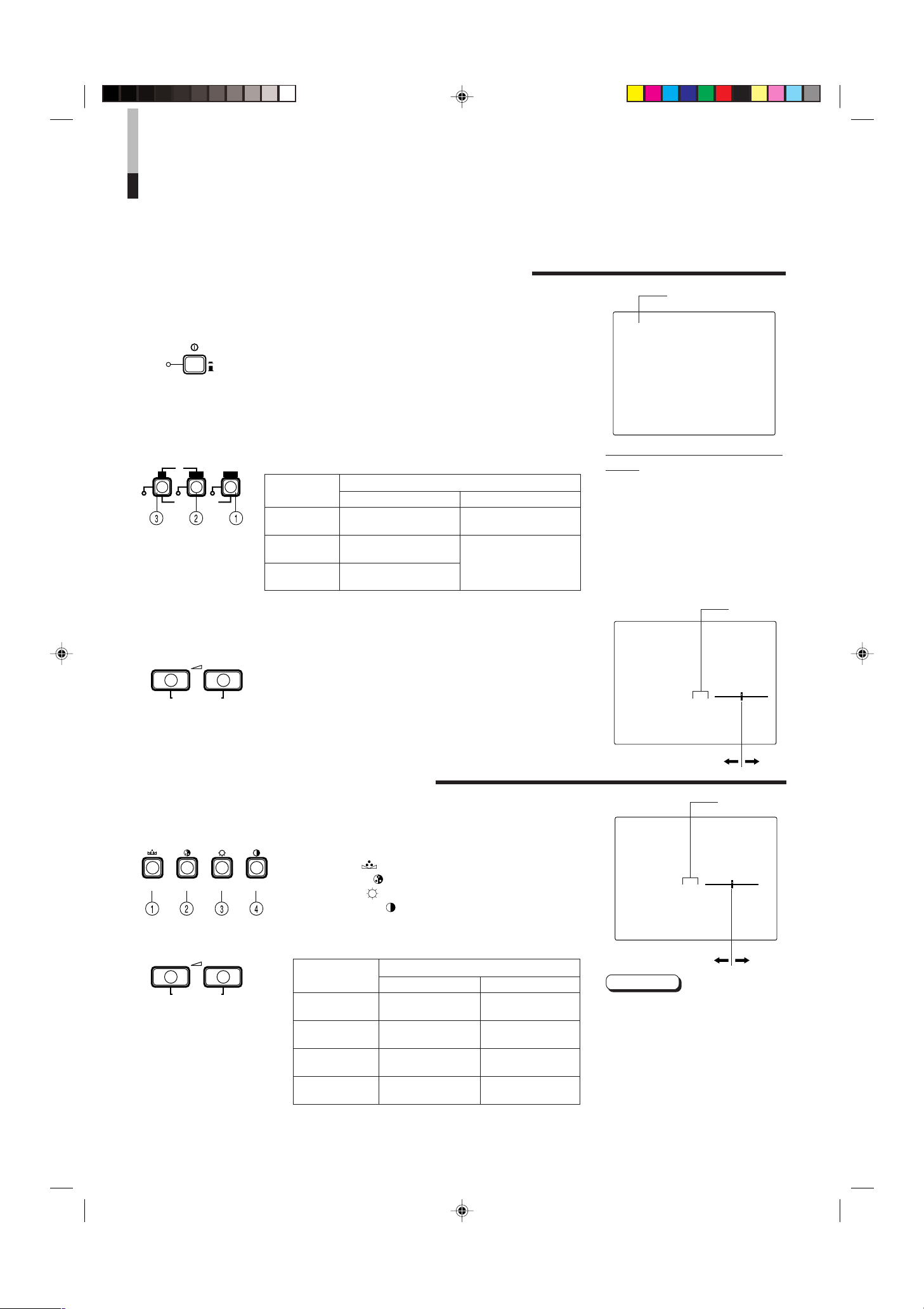
POUR EFFECTUER LES
PHASE CHROMA BRIGHT CONTRAST
INPUT SELECT
B
A
Y/ C VIDEO VIDEO
POWER
ON
OFF
VOLUME/SELECT
– +
VOLUME/SELECT
– +
+
–
+
–
OPÉRATIONS DE BASE
FONCTIONNEMENT DE BASE
1. Appuyer sur l’interrupteur POWER pour mettre
l’alimentation en marche.
_ ON : L’alimentation est en marche.
(Indicateur d’alimentation: allumé)
— OFF : L’alimentation est coupée.
(Indicateur d’alimentation: éteint)
2. Appuyer sur la touche INPUT SELECT pour choisir
l’entrée.
3. Appuyer sur la touche VOLUME/SELECT pour
ajuster le volume du haut-parleur.
Sélectionner l’entrée des signaux vidéo/audio aux prises sur le
panneau arrière.
Touche INPUT
SELECT
1 Entrée A
(VIDEO)
2 Entrée B
(VIDEO)
3 Entrée B
(Y/C)
Appuyer sur la touche pour afficher sur l’écran le niveau de
volume du haut parleur.
+ : Le volume du haut-parleur incorporé est augmenté. (00 à 50)
– : Le volume du haut-parleur incorporé est descendu. (50 à 00)
* L’indication sur écran disparaîtra au bout de 10 secondes
après l’opération.
Entrée de signal vidéo
Prises VIDEO A
Prises VIDEO B
Prises VIDEO B (Y/C)
Prises sur le panneau arrière
Entrée de signal audio
Prises AUDIO A
Prises AUDIO B
Indication de système
couleur (PAL ou NTSC)
PAL
En rapport avec l’indication de système
couleur
● Avec le réglage COLOR SYSTEM réglé en
mode AUTO, lorsque vous mettez
l’alimentation en marche ou sélectionnez
des entrées, l’indication du système
couleur apparaît pendant 3 secondes
environ sur l’écran alors que des signaux
PAL ou NTSC sont détectés.
Elle n’apparaît pas en recevant un signal
noir et blanc ou si aucun signal n’est entré.
Voir page 7 pour le réglage de système
couleur (COLOR SYSTEM).
00 ~ 50
VOLUME : 20
RÉGLAGE DE L’IMAGE
1. Appuyer sur la touche de sélection correspondant
à l’item que vous voulez ajuster.
L’item que vous avez sélectionné est affiché sur l’écran.
1 PHASE ( ) : Commande de phase
2 CHROMA ( ) : Commande de chrominance
3 BRIGHT ( ) : Commande de luminosité
4 CONTRAST ( ) : Commande de contraste
2. Ajuster avec la touche VOLUME/SELECT.
Items
PHASE
(Phase)
CHROMA
(Chrominance)
BRIGHT
(Luminosité)
CONTRAST
(Contraste)
*L’indication de l’écran disparaîtra au bout de 10 secondes
après l’opération.
Touche VOLUME/SELECT
–
Rougeâtre
Plus clair
Plus foncé
Plus faible
Plus profond
Plus lumineux
+
Verdâtre
Plus haut
–20 ~ +20
PHASE : 00
Remarques:
● La commande de phase n’est
effective que dans le mode de
système couleur NTSC.
● La commande Chroma n’a pas d’effet
en recevant un signal noir et blanc ou
si aucun signal n’est entré.
● Lorsque la commande Chroma est
réglée au niveau “-20”, l’image
devient monochrome.
● “NO EFFECT” est affiché (pendant
3 secondes environ) si une fonction
sélectionnée n’a pas d’effet.
6
LCT0053-002A-H (FR) 02.07.30, 2:59 PM6
Page 41

POUR UTILISER LES FONCTIONS
PHASE CHROMA BRIGHT CONTRAST MENU VOLUME/SELECT
– +
EXIT
SHARPNESS
COLOR TEMP.
COLOR SYSTEM
ASPECT RATIO
BRIGHTNESS P.S.
MENU
MENU
VOLUME/SELECT
– +
PHASE CHROMA
6500 9300
AUTO NTSC AUTO PAL
4 – 3 16 – 9
OFF ON
00 +1 +2 +3 +4 +5
DE MENU
AFFICHAGE ET SÉLECTION DANS LE MODE
D’ÉCRAN <MENU> (RÉGLAGE)
Vous pouvez régler les items de menu suivants.
Les régler en fonction de vos besoins.
• SHARPNESS • ASPECT RATIO
• COLOR TEMP. • BRIGHTNESS P.S.
• COLOR SYSTEM
1. Appuyer sur la touche MENU.
L’écran <MENU> est affiché.
2. Appuyer sur la touche PHASE ( ) ou CHROMA
(
) pour sélectionner les items du menu.
Un repère de sélection (3) est mis près de l’item sélectionné.
Écran <MENU>
1
< MENU >
‰ SHARPNESS : 00
2
COLOR TEMP. : 6500
COLOR SYSTEM : AUTO
ASPECT RATIO : 4–3
BRIGHTNESS P.S. : OFF
3
4
Touche du
panneau avant
PHASE ( )
CHROMA ( )
Fonction
affichée
∞
5
Contenu
Repère de sélection avant (3)
Repère de sélection inverse (3)
3. Appuyer sur la touche VOLUME/SELECT pour régler.
Touche du
panneau avant
VOLUME/
SELECT (+)
VOLUME/
SELECT (–)
Items de menu
SHARPNESS
COLOR TEMP.
COLOR SYSTEM
ASPECT RATIO
BRIGHTNESS P.S.
* Normalement, régler le système couleur sur le mode AUTO. Si la réception dans le mode
AUTO n’est pas bonne, le régler sur le mode exclusif (NTSC ou PAL) correspondant au
système couleur du signal reçu.
Netteté de l’image
Température de couleur de
la balance des blancs
Système couleur
Rapport d’image
Fonction d’écrêtage de
luminosité
Objectif
Fonction
affichée
+
3
–
2
Contenu
Augmente (vers valeur maximale)
Fait avancer la valeur de réglage
Diminue (vers valeur minimale)
Fait reculer la valeur de réglage
Gamme de réglage
4. Si vous voulez régler les autres items du menu,
reprendre les procédures 2 et 3.
5. Appuyer sur la touche MENU pour quitter.
Touche du
panneau avant
MENU
Fonction
affichée
SORTIE
(EXIT)
Contenu
Quitter (ou relâcher) l’écran
<MENU>
<Touches du panneau avant>
1
Repère de sélection (3): Indique
l’item de menu que vous sélectionnez.
2 Item de menu: Les items de menu
que vous sélectionnez.
3 Affichage de réglage: Indique les
réglages courants (valeur).
4 Affichage de fonction: Les fonctions
des touches du panneau avant
(7 touches sur la gauche.) correspondent à la fonction affichée.
Fonction
affichée
∞
Fait avancer l’item de menu
5
Fait reculer l’item de menu
Fait diminuer la valeur du
–
réglage (vers le minimum)
Fait augmenter la valeur du
+
réglage (vers le maximum)
3
Fait avancer la valeur de réglage
2
Fait reculer la valeur de réglage
EXIT
Pour sortir de l’écran <MENU>
Remarques:
● BRIGHTNESS P.S. (ou B.P.S) signifie
suppression de crête de luminosité ou
écrêtage de luminosité. Cette fonction est
utilisée pour supprimer (écrêter) la partie
crête blanche de l’image, faisant ainsi pour
réduire le brûlage d’image sur l’écran (tube
à rayons cathodiques).
Lorsque la fonction BRIGHTNESS P.S. (ou
●
B.P.S.) est sur ON, la partie crête blanche
supprimée (par exemple, la partie allumée
d’une lampe fluorescente) semble être floue.
Si nécessaire, baisser le réglage pour B.P.S.
LEVEL dans le mode d’écran <SET-UP
MENU>, ou couper la fonction BRIGHTNESS P.S..
● Lorsque le rapport d’image de l’écran est
réglé sur 16-9 (16:9), l’image sera réduite
verticalement.
Si REMOTE est affiché dans les valeurs de
●
réglage ASPECT RATIO ou BRIGHTNESS
P.S. dans l’écran <MENU>, REMOTE
SELECT est réglé sur “ASPT” ou “B.P.S.”
dans l’écran <SET-UP MENU>. Dans ce cas,
il n’est pas possible d’ajuster les réglages
pour ASPECT RATIO et BRIGHTNESS P.S.
Si vous avez besoin de faire des ajustements,
utiliser la fonction de commande externe ou
couper le réglage REMOTE SELECT.
Contenu
FRANÇAIS
LCT0053-002A-H (FR) 02.07.30, 2:59 PM7
7
Page 42

POUR UTILISER LES FONCTIONS
H. POSITION
V. POSITION
WHITE BALANCE
CONTROL LOCK
B.P.S. LEVEL
REMOTE SELECT
PHASE CHROMA BRIGHT CONTRAST MENU VOLUME/SELECT
– +
EXIT
MENUPHASE
PHASE CHROMA
VOLUME/SELECT
– +
DE MENU
(Suite)
AFFICHAGE ET SÉLECTION DANS LE MODE
D’ÉCRAN <SET-UP MENU> (RÉGLAGE)
Vous pouvez régler les items de menu suivants.
• H. POSITION • WHITE BALANCE • B.P.S. LEVEL
• V. POSITION • CONTROL LOCK • REMOTE SELECT
Remarques:
● Les paramètres pour H. POSITION et V. POSITION peuvent être réglés séparément en
fonction de l’entrée vidéo (Entrée A (VIDEO), Entrée B (VIDEO) ou Entrée B (Y/C))
sélectionnée par les touches de sélection d’entrée sur le panneau avant.
Sélectionner à l’avance l’entrée vidéo requise avec les touches de sélection d’entrée
sur le panneau avant.
● WHITE BALANCE peut être réglée individuellement à 6500 ou 9300 pour la valeur de la
température de couleur.
Régler à l’avance COLOR TEMP. sur la valeur 6500 ou 9300 de l’écran <MENU>.
1. Tout en appuyant sur la touche PHASE ( ),
appuyer sur la touche MENU.
L’écran <SET-UP MENU> est affiché.
2. Appuyer sur la touche PHASE ( ) ou CHROMA
) pour sélectionner l’item de menu souhaité.
(
Un repère de sélection (3) est placé près de l’item sélectionné.
Touche du
panneau avant
PHASE ( )
CHROMA ( )
Fonction
affichée
∞
5
Contenu
Repère de sélection avant (3)
Repère de sélection inverse (3)
3. Appuyer sur la touche VOLUME/SELECT pour régler.
Touche du
panneau avant
VOLUME/
SELECT (+)
VOLUME/
SELECT (–)
Remarque:
● Pour le réglage WHITE BALANCE, sélectionner l’écran de
réglage CUT OFF ou DRIVE, puis sélectionner les touches
(PHASE/CHROMA/BRIGHT) correspondant à la fonction
indiquée (R/G/B).
Fonction
affichée
+
3
Couper
(CUTO)
–
2
Drive
(DRV)
Contenu
Augmente (vers valeur maximale)
Fait avancer la valeur de réglage
Sélectionne l’écran de réglage
CUT OFF
Diminue (vers valeur minimale)
Fait reculer la valeur de réglage
Sélectionne l’écran de réglage
DRIVE
Écran <SET-UP MENU>
1
<SET–UP MENU>
‰ H. POSITION : 00
V. POSITION : 00
WHITE BALANCE
CONTROL LOCK : OFF
B. P. S. LEVEL : 10
REMOTE SELECT : OFF
2
<Touches du panneau avant>
1 Repère de sélection (
l’item de menu que vous
sélectionnez.
3
2 Item de menu: Les items de menu
que vous sélectionnez.
3 Affichage de réglage: Indique les
réglages courants (valeur).
4 Affichage de fonction: Les fonctions
des touches du panneau avant
(7 touches sur la gauche.) correspondent à la fonction affichée.
Fonction
affichée
∞
5
–
+
3
2
EXIT
DRV
CUTO
R
G
B
DISP
Fait avancer l’item de menu
Fait reculer l’item de menu
Fait diminuer la valeur du
réglage (vers le minimum)
Fait augmenter la valeur du
réglage (vers le maximum)
Fait avancer la valeur de
réglage
Fait reculer la valeur de
réglage
Pour sortir de l’écran <SET-
UP MENU>
Sélectionne l’ajustement
DRV
Sélectionne l’ajustement
CUT OFF
Ajuste le niveau du signal
rouge
Ajuste le niveau du signal
vert
Ajuste le niveau du signal
bleu
Passe l’affichage ON-
SCREEN sur marche ou
arrêt. (Cette fonction est
effective uniquement en
mode d’ajustement DRIVE
ou CUT OFF.)
Contenu
3
4
): Indique
8
LCT0053-002A-H (FR) 02.07.30, 2:59 PM8
Page 43

–09 –08 • • • • • • –01 00 +01 • • • • • • +08 +09
–09 –08 • • • • • • –01 00 +01 • • • • • • +08 +09
–09 –08 • • • • • • –01 00 +01 • • • • • • +08 +09
–09 –08 • • • • • • –01 00 +01 • • • • • • +08 +09
–09 –08 • • • • • • –01 00 +01 • • • • • • +08 +09
–09 –08 • • • • • • –01 00 +01 • • • • • • +08 +09
OFF ON
00 01 • • • • • • • 09 10 11 • • • • • • • 19 20
OFF ASPT OFF B.P.S.
–09 –08 • • • • • • –01 00 +01 • • • • • • +08 +09
–09 –08 • • • • • • –01 00 +01 • • • • • • +08 +09
MENU
Items de menu de
réglage
H. POSITION
V. POSITION
WHITE BALANCE
DRIVE R.DRIVE
G.DRIVE
B.DRIVE
CUT OFF R. CUT OFF
G. CUT OFF
B. CUT OFF
CONTROL LOCK
B. P. S. LEVEL
REMOTE SELECT
Objectif
Ajuste la position horizontale sur
l’écran (+ : la position horizontale se
décale vers la droite / – : la position
horizontale se décale vers la
gauche)
Ajuste la position verticale sur
l’écran (+ : la position verticale
descend / – : la position verticale
monte)
Ajuste la balance des blancs
Ajuste le niveau rouge
Ajuste le niveau vert
Ajuste le niveau bleu
Ajuste la coupure rouge
Ajuste la coupure verte
Ajuste la coupure bleu
Règle les touches de fonctionnement
sur le panneau avant pour le mode
de verrouillage de commande
Règle le niveau pour la fonction
d’écrêtage de luminosité.
Règle la fonction de commande
externe (ASPECT RATIO ou
BRIGHTNESS P.S.)
Réglages
Sélectionne l’ajustement DRIVE (DRV) ou CUT OFF
(CUTO). Le réglage d’écran est changé au mode de
réglage sélectionné. Sélectionner les touches R/G/B
correspondant à l’affichage de la fonction à ajuster.
* ASPT : ASPECT RATIO
B.P.S. : BRIGHTNESS P.S.
4. Pour régler les autres items de menu de réglage,
reprendre les procédures 2 et 3.
5. Appuyer sur la touche MENU pour quitter.
Touche du
panneau avant
MENU
Fonction
affichée
SORTIE
(EXIT)
Contenu
Quitter (ou relâcher) l’écran
<MENU>
Remarques:
● Lorsque la fonction CONTROL LOCK
est réglée sur marche (ON), appuyer
sur des touches de fonctionnement
du panneau avant fera afficher le
message “CONTROL LOCK ON!” sur
l’écran pendant 3 secondes environ.
● La fonction CONTROL LOCK est
maintenue même quand
l’alimentation est coupée.
● Pour couper la fonction CONTROL
LOCK, tout en maintenant la touche
MENU pressée, appuyer sur la
touche PHASE. Puis régler la fonction
CONTROL LOCK sur l’arrêt (OFF).
● Même lorsque la fonction CONTROL
LOCK est réglée sur ON, les
opérations suivantes sont
disponibles:
– Opération de l’interrupteur
d’alimentation
– Ajustement du volume sonore avec
la touche VOLUME/SELECT.
– Affichage ou fermeture de l’écran
<SET-UP MENU>.
– Commande externe de ASPECT
RATIO ou de BRIGHTNESS P.S.
lorsque REMOTE SELECT est
réglé sur ON.
FRANÇAIS
LCT0053-002A-H (FR) 02.07.30, 2:59 PM9
9
Page 44

POUR INITIALISER LE RÉGLAGE
PHASE MENU
POWER
_ON
—OFF
CONTRAST
VOLUME/SELECT
– +
POWER
ON
OFF
AFFICHAGE D’ÉCRAN ET SÉLECTIONS DANS LE
MODE DE REMISE À ZÉRO <SET-UP MENU>
Vous pouvez régler les items d’écran <MENU> et <SET-UP MENU>, les items de réglage
d’image et le niveau du volume à leurs valeurs réglées en usine (initiales).
1. Appuyer sur l’interrupteur d’alimentation ( ) pour
—
couper l’alimentation (
).
2. Tout en appuyant à la fois sur les touches MENU et
PHASE ( ), appuyer sur l’interrupteur
d’alimentation ( ) pour mettre l’alimentation en
_
marche (
).
L’écran <SET-UP MENU> RESET est affiché.
Remarque:
● L’écran <SET-UP MENU> RESET ne sera pas affiché si
les touches MENU et PHASE sont pressées pendant un
temps très court. Les maintenir pressées jusqu’à ce que
l’écran d’affichage apparaisse.
3. Réglage
L’initialisation est nécessaire.
Appuyer sur la touche CONTRAST ( ).
* Lorsque l’initialisation est terminée, l’écran <SET-UP
MENU> RESET disparaît.
L’initialisation n’est pas nécessaire.
Appuyer sur la touche VOLUME/SELECT [+] ou [–].
* L’initialisation est abandonnée, et l’écran <SET-UP
MENU> RESET disparaît.
Écran <SET-UP MENU> RESET
<SET–UP MENU> RESET
Are you sure ?
“Yes ” then <CONTRAST>
“No” then <+> or <–>
Réglages initiaux
Fonctions Initialisation
(items) (réglage)
Sortes
SHARPNESS 00
COLOR TEMP. 6500
COLOR SYSTEM
ASPECT RATIO 4–3
BRIGHTNESS P.S. OFF
Écran <MENU>
H. POSITION 00
V. POSITION 00
WHITE BALANCE
R. CUT OFF 00
G. CUT OFF 00
B. CUT OFF 00
R. DRIVE 00
G. DRIVE 00
B. DRIVE 00
CONTROL LOCK OFF
Écran <SET-UP MENU>
B.P.S. LEVEL 10
REMOTE SELECT OFF
PHASE 00
CHROMA 00
CONTRAST 00
BRIGHT 00
Réglage de l’image
AUTO
10
LCT0053-002A-H (FR) 02.07.30, 2:59 PM10
VOLUME
Volume
20
Page 45

Moniteur vidéo
TM-2100PN
<un second>
Magnétoscope
REMOTE
(câble de télécommande)
Magnétoscope
Moniteur vidéo
Caméra vidéo
(câble de signal audio)
Audio
Vidéo
(câble de signal vidéo)
: Circulation des signaux
Audio
Vidéo
(câble de signal vidéo)
(câble de signal audio)
REMOTE
(câble de télécommande)
OUTIN
A
B
VIDEO
A
B
AUDIO
REMOTE
OUTIN
OUT
IN
OUT
IN
IN
OUT
Y/ C
OUT
IN
TM-2100PN
PHASECHROMA BRIGHT CONTRAST MENU
INPUT SELECT
VOLUME/SELECT
– +
BA
POWER
_ON
—OFF
Y/ C VIDEO VIDEO
EXEMPLE DE RACCORDEMENT DE
BASE
Remarques:
• Avant de raccorder votre système, s’assurer que tous les appareils sont hors tension.
• L’illustration ci-dessous montre quelques exemples de raccordements différents. Les raccordements des prises peuvent différer
en fonction de l’appareil raccordé. Bien se référer aux instructions fournies avec les appareils que vous raccordez.
• Chaque paire de prises d’entrée (IN) et de sortie (OUT) est raccordée en sonde.
• Si vous ne raccordez pas d’appareil à une prise de sortie (OUT) en sonde, bien s’assurer de ne pas brancher de câble à la prise
de sortie (OUT) en sonde, ce qui ferait passer le commutateur d’impédance de terminaison sur ouvert (fonction de terminaison
automatique).
• En faisant un raccordement en sonde, raccorder les prises d’entrée (IN) et de sortie (OUT) sur le moniteur pour séparer les
appareils vidéo. (Par exemple, si les deux prises sont raccordées au même magnétoscope, une résonnance peut se produire
sauf pendant la lecture. Ce qui est causé par le même signal vidéo “bouclant” entre les magnétoscopes, et ce n’est pas un
mauvais fonctionnement.)
• Sélectionner l’entrée vidéo (INPUT A (VIDEO), INPUT B (VIDEO) ou INPUT B (Y/C)) avec les touches INPUT SELECT sur le
panneau avant.
• La fonction ASPECT RATIO ou BRIGHTNESS P.S. peut être commandée via la prise REMOTE. Pour faire ainsi, régler REMOTE
SELECT dans le mode <SET-UP MENU>. (Se référer aux pages 8 et 9.)
Exemple de raccordement VIDEO A
(Touche de sélection d’entrée A (VIDEO))
Commutateur de commande externe
Circuit ouvert
(ouvert)
Court-circuit
(fermé)
Fonction de
commande
externe
ASPECT RATIO
BRIGHTNESS P.S.
LCT0053-002A-H (FR) 02.07.30, 2:59 PM11
Commutateur de commande externe
Circuit ouvert
(ouvert)
4–3 (4:3)
OFF
Broche
RCA
Court-circuit
(fermé)
16–9 (16:9)
ON
FRANÇAIS
11
Page 46

EXEMPLE DE RACCORDEMENT DE
Moniteur vidéo
TM-2100PN
<un second>
Magnétoscope
Magnétoscope
Moniteur vidéo
Caméra video
(câble de signal audio)
Audio
: Circulation des signaux
Audio
Vidéo
(câble de signal vidéo)
(câble de signal audio)
REMOTE
(câble de télécommande)
OUTIN
A
B
VIDEO
A
B
AUDIO
REMOTE
OUTIN
OUT
IN
OUT
IN
IN
OUT
Y/ C
OUT
IN
Vidéo
(câble de signal vidéo)
REMOTE
(câble de télécommande)
TM-2100PN
PHASECHROMA BRIGHT CONTRAST MENU
INPUT SELECT
VOLUME/SELECT
– +
BA
POWER
_ON
—OFF
Y/ C VIDEO VIDEO
Moniteur vidéo
TM-2100PN
<un second>
Magnétoscope
Magnétoscope
Moniteur vidéo
Caméra vidéo
(câble de signal audio)
Audio
: Circulation des signaux
Audio
(câble de signal audio)
REMOTE
(câble de télécommande)
OUTIN
A
B
VIDEO
A
B
AUDIO
REMOTE
OUTIN
OUT
IN
OUT
IN
IN
OUT
Y/ C
OUT
IN
Y/C (S-vidéo)
(câble de signal Y/C (S-Vidéo))
Y/C (S-vidéo)
(câble de signal Y/C (S-Vidéo))
REMOTE
(câble de télécommande)
TM-2100PN
PHASECHROMA BRIGHT CONTRAST MENU
INPUT SELECT
VOLUME/SELECT
– +
BA
POWER
_ON
—OFF
Y/ C VIDEO VIDEO
BASE
(Suite)
Exemple de raccordement VIDEO B (VIDEO)
(Touche de sélection d’entrée B (VIDEO))
Commutateur de commande externe
Circuit ouvert
(ouvert)
Fonction de
commande
externe
ASPECT RATIO
BRIGHTNESS P.S.
Court-circuit
(fermé)
Commutateur de commande externe
Circuit ouvert
(ouvert)
4–3 (4:3)
OFF
Broche
RCA
Court-circuit
(fermé)
16–9 (16:9)
ON
Exemple de raccordement VIDEO B (Y/C)
(Touche de sélection d’entrée B (Y/C))
Commutateur de commande externe
Circuit ouvert
(ouvert)
Fonction de
commande
externe
ASPECT RATIO
BRIGHTNESS P.S.
Court-circuit
(fermé)
Commutateur de commande externe
Circuit ouvert
(ouvert)
4–3 (4:3)
OFF
Broche
RCA
Court-circuit
(fermé)
16–9 (16:9)
ON
12
LCT0053-002A-H (FR) 02.07.30, 2:59 PM12
Page 47

EN CAS DE DIFFICULTÉS
Des solutions aux problèmes usuels relatifs à votre moniteur sont décrits ici. Si aucune des solutions présentées ici ne
résout le problème, débrancher le moniteur et consulter un revendeur ou un centre de service agréé pour de
l’assistance.
Problèmes
Pas d’alimentation.
Pas d’image avec
l’alimentation en marche.
Pas de son.
Image vibrante.
Pas de couleurs, mauvaise
couleur, ou image sombre.
Image non naturelle, avec
des couleurs irrégulières ou
image distordue.
Des bandes noires
apparaissent dans le haut et
le bas de l’écran, l’image est
compressée verticalement.
La partie crête blanche de
l’image (par exemple, la
partie allumée d’une lampe
fluorescente) est sombre,
manque de netteté, et la
couleur est floue.
La touche du panneau avant
ne fonctionne pas.
Points à vérifier
La fiche d’alimentation est-elle
desserrée ou débranchée ?
Le signal vidéo est-il sorti de l’appareil
raccordé ?
Le signal d’entrée est-il sélectionné
convenablement ?
Le câble vidéo est-il débranché ?
Le signal audio est-il sorti de l’appareil
raccordé ?
La sortie de volume est-elle réglée sur
la position minimale ?
Le câble audio est-il débranché ?
Le moniteur est-il près d’un appareil
générant un champ magnétique
puissant ?
Le système couleur est-il sélectionné
convenablement ?
Le réglage de commande d’image
(CONTRAST, BRIGHT CHROMA ou
PHASE) a-t-il été changé ?
Le moniteur est-il près d’un hautparleur, d’un aimant ou de tout autre
appareil générant un champ magnétique
puissant ?
Le rapport d’image est-il réglé sur
16:9 ?
La fonction BRIGHTNESS P.S. est-elle
réglée sur ON ?
Les touches de fonctionnement sur le
panneau avant sont-elles verrouillées ?
(La fonction CONTROL LOCK a-t-elle
été réglée sur ON ?)
Mesures
Introduire fermement la fiche d’alimentation.
Régler correctement l’appareil raccordé.
Sélectionner l’entrée de signal vidéo requise avec
la touche de sélection d’entrée. (Voir page 6.)
Raccorder fermement le câble de signal vidéo.
(Voir pages 11 et 12.)
Régler correctement l’appareil raccordé.
Ajuster le volume du haut-parleur avec la touche
VOLUME/SELECT. (Voir page 6.)
Raccorder fermement le câble de signal audio.
(Voir pages 11 et 12.)
Éloigner l’appareil du moniteur jusqu’à ce que
l’image se stabilise.
Régler COLOR SYSTEM dans le mode d’écran
<MENU> sur le mode [AUTO]. (Voir page 7.)
Régler chaque commande d’image sur le
réglage standard. (Voir page 6.)
Eloigner l’appareil du moniteur et couper
l’alimentation du moniteur. Attendre au moins 30
minutes, puis remettre l’alimentation en marche.
Régler ASPECT RATIO dans le mode d’écran
<MENU> sur [4:3 (4-3)]. (Voir page 7.)
En commandant de façon externe, ASPECT
RATIO doit être réglé sur [4:3 (4-3)]. (Voir pages
11 et 12.)
Régler la fonction BRIGHTNESS P.S. dans le
mode d’écran <MENU> sur OFF. (Voir page 7.)
En commandant de façon externe, la fonction
BRIGHTNESS P.S. doit être réglée sur OFF. (Voir
pages 11 et 12.)
Régler CONTROL LOCK sur OFF dans le mode
d’écran <SET-UP MENU>. (Voir pages 8 et 9.)
FRANÇAIS
La suite n’est pas des mauvais fonctionnements:
● Si une image fixe lumineuse (tel un vêtement blanc) est affiché pendant une longue période, elle peut apparaître colorée. C’est à
cause de la structure du tube à rayons cathodiques et ce sera effacé quand une autre image est affichée.
● Vous pouvez ressentir une légère décharge électrique lorsque vous touchez le tube image. Ce phénomène est produit par une
accumulation normale d’électricité statique sur le tube à rayons cathodiques et ce n’est pas dangereux.
● Le moniteur émet un son étrange lorsque la température de la pièce change soudainement. C’est uniquement un problème si
une anomalie apparaît également sur l’écran.
LCT0053-002A-H (FR) 02.07.30, 2:59 PM13
13
Page 48

CARACTÉRISTIQUES
TECHNIQUES
MODÈLE
Type
Système couleur
Tube image
Taille effective de l’écran
Fréquence de balayage
Résolution horizontale
Prises d’entrée VIDEO A
VIDEO B
TM-2100PN
Moniteur vidéo couleur
PAL, NTSC (3,58)
54 cm mesuré en diagonale, type à coins carrés, déviation de 90°,
canon en ligne, type à triplets en ligne verticale
(maille de bande phosphore de 0,69 mm)
Largeur 406,4 mm
Hauteur 304,8 mm
Diagonale 508 mm
(H) 15,734 kHz (NTSC), 15,625 kHz (PAL)
(V) 59,94 kHz (NTSC), 50 Hz (PAL)
450 lignes TV ou plus (mode d’entrée Y/C)
Vidéo composite: 1 ligne, connecteur BNC x 2, 1 V(cc), 75 Ω, synchro
négative (raccordement en sonde possible, terminaison automatique)
Vidéo composite: 1 ligne, connecteur BNC x 2, 1 V(cc), 75 Ω, synchro
négative (raccordement en sonde possible, terminaison automatique)
Y/C séparé: 1 ligne, connecteur mini-DIN à 4 broches x 2
Y: 1,0 V(cc), 75 Ω
C: 0,286 V(cc), 75 Ω (NTSC), 0,3 V(cc), 75 Ω (PAL)
(raccordement en sonde possible, terminaison automatique)
AUDIO A
AUDIO B
REMOTE
Sortie de puissance audio
Haut-parleur incorporé
Conditions ambiantes
Alimentation
Consommation
Dimensions
Poids
Accessoire
1 ligne (monophonique), broche RCA x 2, 0,5 V(rms),
haute impédance (raccordement en sonde possible)
1 ligne (monophonique), broche RCA x 2, 0,5 V(rms),
haute impédance (raccordement en sonde possible)
1 ligne, broche RCA x 2 (raccordement en sonde possible)
1 W (monophonique)
Rond de 8 cm x 1, impédance de 8 Ω
Température de fonctionnement: 0°C à 40°C
Humidité de fonctionnement: 20 % à 80 % (sans condensation)
230 V CA, 50 Hz/60 Hz
0,72 A (230 V CA)
Largeur 476 mm
Hauteur 407,5 mm
Profondeur 492 mm
28,5 kg
Cordon d’alimentation secteur (2 m) x 1
* Les illustrations utilisées dans ce manuel sont uniquement dans un but d’explication. L’apparence du produit réel peut légèrement différer.
* Les dimensions et le poids sont approximatifs.
* Erreurs et omissions possibles. Présentation et caractéristiques techniques modifiables sans préavis.
14
LCT0053-002A-H (FR) 02.07.30, 2:59 PM14
Page 49

Dimensions
4
2
3
4
3
1
2
1
OUT
IN
Y/C
4791,3 9,5
105
492
135 128,5
50,2
3,5
416,4
*
476
382,8
314,8
*
407,5
TM-2100PN
PHASE CHROMA BRIGHT
CONTRAST
MENU
INPUT SELECT
VOLUME/SELECT
– +
BA
POWER
ON
OFF
Y/ C VIDEO VIDEO
Unités: mm
< Vue de face >
* Des astérisques (*) sont utilisés pour indiquer les
dimensions du panneau avant.
< Vue latérale >
Affectation des broches de la
prise Y/C
No. de
broche
1 Masse (Y)
2 Masse (C)
3Y
4C
Signal
FRANÇAIS
LCT0053-002A-H (FR) 02.07.30, 2:59 PM15
15
Page 50

ï /ï /îí 02.07.30, 3:23 PM4
Page 51

MANUALE DI ISTRUZIONI
MONITOR VIDEO A COLORI
TM-2100PN
LCT0053-002A-H (IT) 02.07.30, 3:01 PM1
ITALIANO
1
Page 52

Vi ringraziamo per aver acquistato questo monitor video a colori. Prima di usarlo, leggere
attentamente queste istruzioni per poter trarre pieno vantaggio dalle sue caratteristiche.
NORME DI SICUREZZA
Per evitare incidenti fatali causati da errori di operazione o di
installazione, leggere e tenere presente le seguenti
avvertenze.
AVVERTENZE
Per evitare folgorazioni o pericoli d’incendio, non esporre
il monitor a pioggia o umidità. Al suo interno sono
presenti voltaggi di livello pericoloso. Non rimuovere il
pannello posteriore.
Per ogni riparazione al monitor, entrare in contatto con
personale qualificato. Non tentare mai di fare da sé.
AVVERTENZA: QUESTO
APPARECCHIO
DEVE VENIRE
MESSO A TERRA.
PRECAUZIONI
● Usare solo corrente elettrica dalle caratteristiche specifi-
cate.
● Se si prevede di non dover usare l’unità per qualche tempo
o se la si deve pulire, scollegare il cavo di alimentazione
dalla presa di corrente alternata.
● Non permettere ad alcun oggetto di pesare sul cavo di
alimentazione e non stendere il cavo in posizioni in cui
possa venire calpestato. Non sovraccaricare le prese di
corrente o i cavi di alimentazione, dato che ciò può
risultare in incendi o folgorazioni.
● Evitare di usare l’unità in luoghi:
– molto caldi, molto freddi o molto umidi.
– polverosi,
– vicino ad apparecchi che generino forti campi magnetici
– esposti a luce solare diretta,
– poco ventilati,
– automobili chiuse
● Non coprire le fessure di ventilazione durante l’uso
dell’apparecchio, dato che esso si potrebbe surriscaldare
eccessivamente.
● Se lo schermo si impolvera, pulirlo con un panno morbido e
pulito.
● Nei seguenti casi, scollegare la spina di alimentazione dalla
sua presa e chiamare personale tecnico autorizzato.
Ordinanza 3 sul rumore prodotto da macchine, GSGV,
18 gennaio 1991:
Secondo le norme ISO 7779, il livello del suono nella
posizione dell’operatore deve essere uguale o minore a
70 dB (A).
– Se il cavo di alimentazione o la spina fossero stati
danneggiati.
– Se del liquido fosse stato versato su di esso
– Se il prodotto fosse stato fatto cadere o danneggiato
– Se il prodotto mostra un apprezzabile calo di prestazioni.
● Non tentare di riparare il prodotto da sé e non aprirlo per
qualsiasi motivo, dato che ciò vi esporrebbe a correnti di
livello pericoloso. Affidare ogni riparazione a personale
specializzato.
● Se vengono sostituite delle parti, ottenere dal tecnico una
dichiarazione scritta in cui dichiara che i ricambi sono di
qualità e tipo equivalenti agli originali. Usando pezzi di
ricambio originali si possono prevenire incendi, folgorazioni
ed altri incidenti.
● Al completamento di qualsiasi operazioni di assistenza
tecnica, richiedere l’esecuzione dei controlli descritti nel
manuale di servizio che accompagna il prodotto.
● Per sbarazzarsi dell’unità al termine della sua vita utile,
affidarsi a personale specializzato. Il tubo dell’immagine può
implodere.
PERMANENZA DI IMMAGINI SULLO SCHERMO
● Si raccomanda di non lasciare una stessa immagine sullo schermo per molto tempo e di non visualizzare immagini con la
luminosità al massimo.
Ciò potrebbe lasciare tracce permanenti dell’immagine sul monitor. Il problema non sussiste invece se si visualizzano normali
filmati.
2
LCT0053-002A-H (IT) 02.07.30, 3:01 PM2
Page 53

INDICE
NORME DI SICUREZZA................................................................................... 2
COMANDI E LORO CARATTERISTICHE ....................................................... 4
FUNZIONI BASE DELL’UNITA ........................................................................ 6
USO DELLE FUNZIONI DEL MENU ................................................................ 7
RIPRISTINO DELLE IMPOSTAZIONI STANDARD ....................................... 10
UN ESEMPIO DI COLLEGAMENTO ..............................................................11
DIAGNOSTICA ............................................................................................... 13
DATI TECNICI................................................................................................. 14
LCT0053-002A-H (IT) 02.07.30, 3:01 PM3
ITALIANO
3
Page 54

COMANDI E LORO
TM-2100PN
PHASE CHROMA BRIGHT
CONTRAST
MENU
INPUT SELECT
VOLUME/SELECT
– +
BA
POWER
ON
OFF
Y/ C VIDEO VIDEO
15
TM-2100PN
PHASE CHROMA BRIGHT CONTRAST MENU
INPUT SELECT
VOLUME/SELECT
– +
BA
POWER
ON
OFF
Y/ C VIDEO VIDEO
1 3
2 4 6 8
5 7 9 11
12 13 14
10
CARATTERISTICHE
LATO ANTERIORE
<PANNELLO ANTERIORE>
1
Tasti di messa in fase [PHASE ]
Premere questo tasto per impostare il modo di
regolazione del colore. Regolare quindi il valore del
parametro con i tasti VOLUME/SELECT. Viene usato
anche come tasto di controllo nel modo delle funzioni del
menu.
Tasto della crominanza [CHROMA ]
2
Premere questo tasto per impostare il modo di
regolazione della densità del colore. Regolare quindi il
valore del parametro con i tasti VOLUME/SELECT. Viene
usato anche come tasto di controllo nel modo delle
funzioni del menu.
Tasto della luminosità [BRIGHT ]
3
Premere questo tasto per impostare il modo di
regolazione della luminosità. Regolare quindi il valore del
parametro con i tasti VOLUME/SELECT. Viene usato
anche come tasto di controllo nel modo delle funzioni del
menu.
Tasto del contrasto [CONTRAST ]
4
Premere questo tasto per impostare il modo di
regolazione del contrasto. Regolare quindi il valore del
parametro con i tasti VOLUME/SELECT. Viene usato
anche come tasto di controllo nel modo delle funzioni del
menu.
Tasto del menu [MENU]
5
Visualizza ed esce dallo schermo <MENU>.
Premendo il tasto PHASE col tasto MENU premuto si fa
comparire il menu <SET-UP MENU>.
Tasti del volume/di selezione [VOLUME/
6
SELECT –
Regolano il volume dell’altoparlante. Vengono anche usati
per controllare il menu delle funzioni.
Tasto di ingresso B (Y/C) [INPUT SELECT B
7
Y/C ]
Seleziona l’ingresso del segnale video al terminale VIDEO
B (Y/C) (connettore mini DIN a 4 contatti) e l’ingresso del
segnale audio al terminale AUDIO B (connettore RCA)
situati sul pannello posteriore. Quando selezionato,
l’indicatore dell’ingresso B (Y/C)
+]
@ si accende.
Tasto di ingresso B (VIDEO) [INPUT SELECT
8
B VIDEO ]
Seleziona l’ingresso del segnale video al terminale VIDEO
B (connettore BNC) e l’ingresso del segnale audio al
terminale AUDIO B (connettore RCA) situati sul pannello
posteriore. Quando selezionato, l’indicatore dell’ingresso
# si accende.
B
Tasto di ingresso A (VIDEO) [INPUT SELECT
9
A VIDEO ]
Seleziona l’ingresso del segnale video al terminale VIDEO
A (connettore BNC) e l’ingresso del segnale audio al
terminale AUDIO A (connettore RCA) situati sul pannello
posteriore. Quando selezionato, l’indicatore dell’ingresso
$ si accende.
A
Indicatore di accensione
10
Si accende di colore verde quando l’unità è accesa (su
ON).
Acceso : quando l’unità è accesa (su ON).
Spento : quando l’unità è spenta (su OFF).
Interruttore di alimentazione [POWER ]
11
Premendo questo tasto l’unità si accende (ON) o si
spegne (OFF).
_ ON : l’unità è accesa.
— OFF : l’unità è spenta.
Indicatore d’ingresso B (Y/C)
12
Si illumina di luce verde quando l’ingresso B (Y/C) viene
scelto.
Indicatore d’ingresso B (VIDEO)
13
Si illumina di luce verde quando l’ingresso B (VIDEO)
viene scelto.
Indicatore d’ingresso A (VIDEO)
14
Si illumina di luce verde quando l’ingresso A (VIDEO)
viene scelto.
Altoparlante
15
L’altoparlante incorporato si trova all’interno del pannello
laterale destro quando il monitor viene visto da davanti.
4
LCT0053-002A-H (IT) 02.07.30, 3:01 PM4
Page 55

OUTIN
A
B
VIDEO
A
B
AUDIO
REMOTE
OUTIN
OUT
IN
OUT
IN
IN
OUT
Y/ C
OUT
IN
22
23
LATO POSTERIORE
OUTIN
A
B
VIDEO
A
B
AUDIO
REMOTE
OUTIN
OUT
IN
OUT
IN
IN
OUT
Y/ C
OUT
IN
16
17
18
19
20
21
<PANNELLO POSTERIORE>
Ad una presa di corrente
alternata di rete (230 V di
c.a., 50 Hz/60 Hz)
Terminali video A [VIDEO A IN/OUT]
16
Terminali di ingresso (IN) ed uscita (OUT) del segnale
video. I terminali di uscita sono collegati fra loro a ponte.
IN : terminali di ingresso video
OUT : terminali di uscita video collegati fra loro a ponte.
Note:
* Come segnale audio, usare quello dei terminali AUDIO A
(.
* Consultare anche la sezione UN ESEMPIO DI
COLLEGAMENTO alle pagine 11 e 12 di questo manuale.
Terminali video B [VIDEO B IN/OUT]
17
Terminali di ingresso (IN) ed uscita (OUT) del segnale
video. I terminali di uscita sono collegati fra loro a ponte.
IN : terminali di ingresso video
OUT : terminali di uscita video collegati fra loro a ponte.
Note:
* Come segnale audio, usare quello dei terminali AUDIO
).
B
* Consultare anche la sezione UN ESEMPIO DI
COLLEGAMENTO alle pagine 11 e 12 di questo manuale.
Terminali video B (Y/C) [VIDEO B Y/C IN/
18
OUT]
Dei terminali di ingresso (IN) ed uscita (OUT).
I terminali di uscita sono collegati fra loro a ponte.
IN : terminali S-Video di ingresso separato Y/C
OUT : terminali di uscita video collegati fra loro a ponte.
Note:
* Come segnale audio, usare quello dei terminali AUDIO
B ).
* Consultare anche la sezione UN ESEMPIO DI
COLLEGAMENTO alle pagine 11 e 12 di questo manuale.
Terminali audio A [AUDIO A IN/OUT]
19
Terminali audio di ingresso (IN) ed uscita (OUT) del
segnale corrispondente ai terminali VIDEO A ^.
I terminali di uscita sono collegati a ponte fra loro.
IN : terminali di ingresso audio
OUT : terminali di uscita audio collegati a ponte fra loro
Terminali audio B [AUDIO B IN/OUT]
20
Terminali audio di ingresso (IN) ed uscita (OUT) del
segnale corrispondente ai terminali VIDEO B
& o VIDEO
B (Y/C) *. I terminali di uscita sono collegati a ponte fra
loro.
IN : terminali di ingresso audio
OUT : terminali di uscita audio collegati a ponte fra loro
Note:
* Come segnale video, usare quello dei terminali VIDEO B
& o VIDEO B (Y/C) *.
* Consultare anche la sezione UN ESEMPIO DI
COLLEGAMENTO alle pagine 11 e 12 di questo manuale.
Terminali remoti [REMOTE IN/OUT]
21
Terminali di ingresso (IN) e di uscita (OUT) per controllo
esterno. Il terminale di uscita è collegato a ponte. Il
controllo esterno è disponibile sia per selezionare la
funzione ASPECT RATIO sia per selezionare su ON o su
OFF nel modo di funzionamento BRIGHTNESS P.S. Il
controllo esterno va impostato dallo schermo <SET-UP
MENU>.
Funzioni di
controllo
dall’esterno
ASPECT RATIO 4-3 (4:3) 16-9 (16:9)
BRIGHTNESS P.S.
Nota:
● Consultare anche la sezione UN ESEMPIO DI
COLLEGAMENTO alle pagine 11 e 12 di questo manuale.
Presa di corrente alternata [AC IN]
22
Connettore di alimentazione. Collegare il cavo di
alimentazione in dotazione
alternata (230 V, 50 Hz/60 Hz).
Cavo di alimentazione
23
Collegarlo ad una presa di corrente alternata da 230 V,
50 Hz/60 Hz ed al connettore AC IN.
Interruttore di controllo dall’esterno
Circuito aperto Circuito chiuso
(aperto) (in corto)
OFF ON
e ad una presa di corrente
ITALIANO
Note:
* Come segnale video, usare quello dei terminali VIDEO A
LCT0053-002A-H (IT) 02.07.30, 3:01 PM5
^.
* Consultare anche la sezione UN ESEMPIO DI
COLLEGAMENTO alle pagine 11 e 12 di questo manuale.
5
Page 56

FUNZIONI BASE DELL’UNITA
PHASE CHROMA BRIGHT CONTRAST
INPUT SELECT
B
A
Y/ C VIDEO VIDEO
POWER
ON
OFF
VOLUME/SELECT
– +
VOLUME/SELECT
– +
+
–
+
–
USO BASE
1. Premere il tasto POWER in modo da far accendere
l’unità.
_ON : L’unità si accende e l’indicatore di alimentazione si
illumina.
—OFF : L’apparecchio si spegne (indicatore di accensione:
Spento)
2. Premere il tasto INPUT SELECT per scegliere un
ingresso di segnale.
Sceglie un set di terminali di ingresso audio e video del
pannello posteriore.
Tasto INPUT
SELECT
1
Ingresso A
(VIDEO)
2
Ingresso B
(VIDEO)
3
Ingresso B
(Y/C)
3. Premere il tasto VOLUME/SELECT per regolare il
volume dell’altoparlante.
Premere questo tasto per visualizzare il livello del volume
dell’altoparlante sullo schermo.
+ : il volume dell’altoparlante incorporato aumenta (da 00 a 50).
– : il volume dell’altoparlante incorporato diminuisce (da 50 a 00).
* L’indicazione sullo schermo scompare circa 10 secondi
dopo che si è premuto un tasto.
Terminali del pannello posteriore
Ingresso segnale video Ingresso segnale
Terminali VIDEO A Terminali AUDIO A
Terminali VIDEO B
Terminali AUDIO B
Terminali VIDEO B (Y/C)
audio
Indicazione del sistema
colore (PAL o NTSC)
PAL
Riguardo all’indicazione del sistema
colore
● Con il comando COLOR SYSTEM su
AUTO, se si accende l’unità o si
scelgono ingressi di segnale,
l’indicazione del sistema del colore
appare per 3 secondi sullo schermo
mentre i segnali PAL o NTSC
vengono ricevuti.
Non appare invece quando si riceve
un segnale in bianco e nero o non ne
viene ricevuto affatto.
Per l’impostazione della funzione
COLOR SYSTEM vedere a pagina 7.
00 ~ 50
VOLUME : 20
REGOLAZIONE DELL’IMMAGINE
1. Premere il selettore corrispondente al parametro
che si desidera regolare.
La voce scelta viene visualizzata sullo schermo.
1 PHASE ( ) : controllo della fase
2 CHROMA ( ) : controllo della crominanza
3 BRIGHT ( ) : controllo della luminosità
4 CONTRAST ( ) : controllo del contrasto
2. Regolare quindi il parametro col tasto VOLUME/
SELECT.
Voci Botón VOLUME/SELECT
– +
PHASE
(fase)
CHROMA
(crominanza)
BRIGHT
(luminosità)
CONTRAST
(contrasto)
* L’indicazione sullo schermo scompare circa 10 secondi dopo
la pressione dei tasti.
Rossastro Verdastro
Più chiaro Più basso
Più scuro Più luminoso
Più basso Più alto
–20 ~ +20
PHASE : 00
Note:
● Il controllo della fase funziona solo
nel modo del colore NTSC.
● Il controllo della crominanza non
funziona durante la riproduzione in
bianco e nero o se non viene ricevuto
alcun segnale.
● Quando il controllo Chroma è
impostato sul livello “-20”, l’immagine
diviene monocromatica.
● Viene visualizzata l’indicazione “NO
EFFECT” per 3 secondi se la
funzione scelta non ha alcun effetto.
6
LCT0053-002A-H (IT) 02.07.30, 3:01 PM6
Page 57
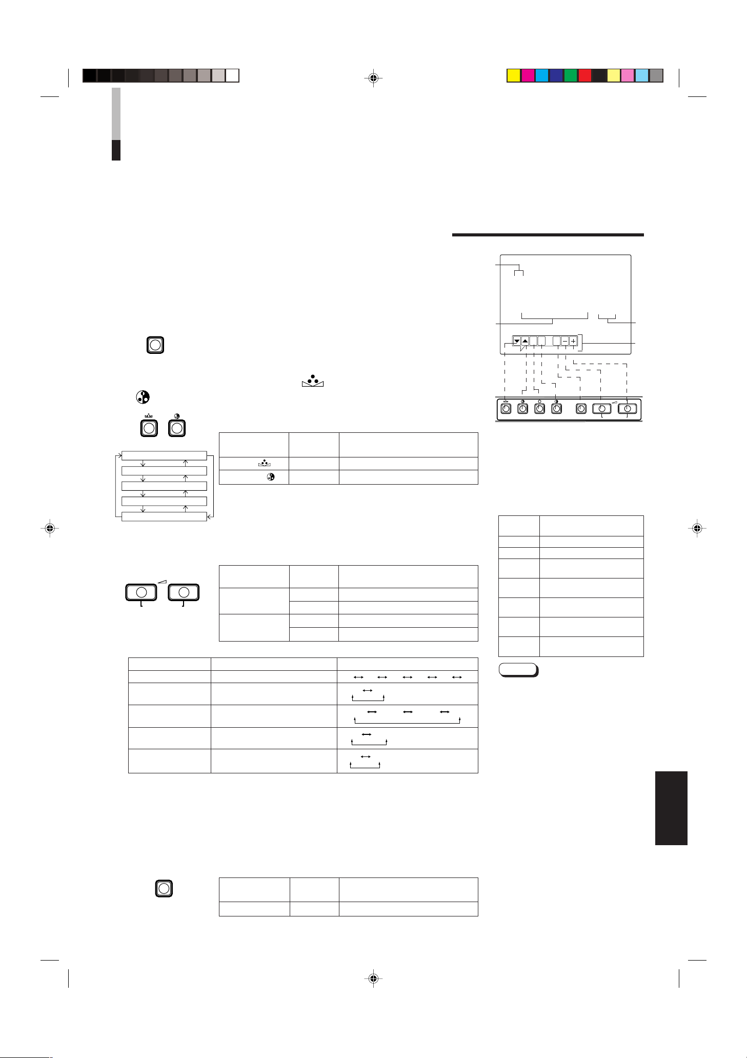
USO DELLE FUNZIONI DEL MENU
PHASE CHROMA BRIGHT CONTRAST MENU VOLUME/SELECT
– +
EXIT
MENU
PHASE CHROMA
SHARPNESS
COLOR TEMP.
COLOR SYSTEM
ASPECT RATIO
BRIGHTNESS P.S.
VOLUME/SELECT
– +
MENU
6500 9300
AUTO NTSC AUTO PAL
4 – 3 16 – 9
OFF ON
00 +1 +2 +3 +4 +5
VISUALIZZAZIONE E SELEZIONE DI VOCI NEL
MODO DEI MENU SULLO SCHERMO
(IMPOSTAZIONE PARAMETRI)
I possono regolare i seguenti parametri.
Regolarli a seconda delle proprie necessità.
• SHARPNESS • ASPECT RATIO
• COLOR TEMP. • BRIGHTNESS P.S.
• COLOR SYSTEM
1. Premere il tasto MENU.
Viene visualizzato lo schermo <MENU>.
2. Premere il tasto PHASE ( ) o quello CHROMA
(
) per scegliere voci del menu MENU.
Accanto alla voce scelta compare un contrassegno (3).
Tasto del
pannello anteriore
PHASE ( ) ∞
CHROMA ( ) 5
3. Premere il tasto VOLUME/SELECT per finalizzare la
scelta fatta.
Tasto del
pannello anteriore
VOLUME/SELECT
(+)
VOLUME/SELECT
(–)
Voci del menu Scopo Gamma regolazione
SHARPNESS Nitidezza immagine
COLOR TEMP
COLOR SYSTEM Sistema di colore
ASPECT RATIO Proporzioni immagine
BRIGHTNESS P.S.
* Normalmente impostate la funzione COLOR SYSTEM sul modo AUTO. Qualora la ricezione in modo AUTO
non sia buona, eseguire l’impostazione sul modo esclusivo (NTSC o PAL) corrispondente al sistema colore
ricevuto.
.
Temperatura colore di
bilanciamento del bianco
Funzione di soppressione
dei picchi di luminosità
4. Per regolare altri parametri, ripetere le procedure
2 e 3.
5. Premere il tasto MENU per abbandonare la funzione.
Tasto del
pannello anteriore
MENU EXIT Abbandono dello schermo <MENU>
Funzione
visualizzata
Contrassegno selezione in avanti (3)
Contrassegno selezione all’indietro (3)
Funzione
visualizzata
+ Aumento (al valore massimo)
3 Fa aumentare il valore del parametro
– Diminuzione (al valore minimo)
2 Fa diminuire il valore del parametro
Funzione
visualizzata
Indice
Indice
Indice
Schermo <MENU>
1
< MENU >
‰ SHARPNESS : 00
COLOR TEMP. : 6500
COLOR SYSTEM : AUTO
ASPECT RATIO : 4–3
BRIGHTNESS P.S. : OFF
2
<Front-Tasten>
1 Contrassegno di selezione (3): Indica
quale voce avete scelto.
2 Voce del menu: Voci del menu che
possono venire scelte.
3 Display di regolazione: Indica il valore
attuale dei parametri.
4 Display di funzione: La funzione dei tasti
del pannello anteriore (7 tasti sulla
sinistra) viene visualizzata sullo schermo.
Funzione
visualizzata
∞ Per avanzare nel menu
5 Per indietreggiare nel menu
Abbassare il valore del
–
parametro (al minimo)
Aumentare il valore del
+
parametro (al massimo)
Fa aumentare il valore del
3
parametro
Fa diminuire il valore del
2
parametro
EXIT
Note:
● BRIGHTNESS P.S. (o B.P.S.) è l’acronimo di
Brightness Peak Suppressor. Questa
funzione viene utilizzata per sopprimere
(tagliare) le porzioni dei picchi bianchi
dell’immagine, in modo da ridurre la
bruciatura dello schermo dovuta
all’immagine stessa (tubo a raggi catodici).
● Quando la funzione BRIGHTNESS P.S. (o
B.P.S.) è su ON, la porzione soppressa dei
picchi bianchi (ad esempio la parte accesa
di una lampada fluorescente) appare
sfuocata.
In caso di necessità, nel <SET-UP MENU>
riducete l’impostazione relativa a B.P.S.
LEVEL, oppure disattivate la funzione
BRIGHTNESS P.S.
● Quando il rapporto di aspetto dello schermo
è impostato su 16-9 (16:9), l’immagine viene
ridotta verticalmente.
● Qualora in <MENU>, nei valori di
impostazione in corrispondenza di ASPECT
RATIO o BRIGHTNESS P.S. appaia
REMOTE, in <SET-UP MENU> la funzione
REMOTE SELECT è impostata su “ASPT”
oppure su “B.P.S.”. In tal caso non è
possibile regolare le gamme di impostazione
relative alle funzioni ASPECT RATIO e
BRIGHTNESS P.S. Qualora sia necessario
effettuare regolazioni, utilizzare la funzione
di controllo esterno oppure impostare su
OFF l’impostazione REMOTE SELECT.
USCITA. Permette di uscire
dallo schermo <MENU>
Indice
3
4
ITALIANO
LCT0053-002A-H (IT) 02.07.30, 3:01 PM7
7
Page 58

USO DELLE FUNZIONI DEL MENU
MENUPHASE
H. POSITION
V. POSITION
WHITE BALANCE
CONTROL LOCK
B.P.S. LEVEL
REMOTE SELECT
VOLUME/SELECT
– +
PHASE CHROMA
PHASE CHROMA BRIGHT CONTRAST MENU VOLUME/SELECT
– +
EXIT
(cont.)
DISPLAY E SELEZIONI POSSIBILI NEL MENU
<SET-UP MENU>
Nel menu (SET-UP MENU) sono disponibili per la regolazione i seguenti parametri.
• H. POSITION • WHITE BALANCE • B.P.S. LEVEL
• V. POSITION • CONTROL LOCK • REMOTE SELECT
Note:
● I parametri H.POSITION e V.POSITION possono venire regolati separatamente a
seconda dell’ingresso video (ingresso A (VIDEO), ingresso B (VIDEO) o ingresso B
(Y/C)) scelto con i selettori d’ingresso del pannello anteriore. Scegliere in anticipo
l’ingresso video desiderato con i selettore appositi del pannello anteriore.
● Il valore WHITE BALANCE della temperatura del colore può venire regolato
individualmente su 6500 o 9300.
Portare in anticipo COLOR TEMP. dello schermo <MENU> sul valore 6500 o 9300.
1. Tenere premuto il tasto PHASE ( ) e premere il
tasto MENU.
Viene visualizzato il menu <SET-UP MENU>.
2. Premere il tasto PHASE ( ) o CHROMA ( ) per
scegliere la voce da regolare.
Un contrassegno (3) appare accanto alla voce scelta.
Tasto del
pannello anteriore
PHASE ( ) ∞
CHROMA ( ) 5
Funzione
visualizzata
Indice
Contrassegno selezione in avanti (3)
Contrassegno selezione all’indietro (3)
3. Premere il tasto VOLUME/SELECT per impostare il
valore del parametro.
Tasto del
pannello anteriore
VOLUME/
SELECT (+)
VOLUME/
SELECT (–)
Nota:
● Per quanto riguarda la regolazione WHITE BALANCE, scegliere lo
schermo di regolazione CUT OFF o DRIVE, quindi scegliere i tasti
(PHASE/CHROMA/BRIGHT) corrispondenti alla funzione indicata
(R/G/B).
Funzione
visualizzata
+ Aumento (al valore massimo)
3 Fa aumentare il valore del parametro
CUTO
– Diminuzione (al valore minimo)
2 Fa diminuire il valore del parametro
DRV
Sceglie lo schermo di regolazione
CUT OFF
Sceglie lo schermo di regolazione
DRIVE
Indice
Schermo <SET-UP MENU>
1
<SET–UP MENU>
‰ H. POSITION : 00
V. POSITION : 00
WHITE BALANCE
CONTROL LOCK : OFF
B. P. S. LEVEL : 10
REMOTE SELECT : OFF
2
<Front-Tasten>
1 Contrassegno di selezione (3):
Indica quale voce avete scelto.
2 Voce del menu: Voci del menu che
possono venire scelte.
3 Display di regolazione: Indica il
valore attuale dei parametri.
4 Display di funzione: La funzione dei
tasti del pannello anteriore (7 tasti
sulla sinistra) viene visualizzata
sullo schermo.
Funzione
visualizzata
∞ Per avanzare nel menu
5 Per indietreggiare nel menu
Abbassare il valore del
–
parametro (al minimo)
Aumentare il valore del
+
parametro (al massimo)
Fa aumentare il valore del
3
parametro
Fa diminuire il valore del
2
parametro
EXIT
DRV
CUTO
DISP
Permette di uscire dallo
schermo <SET-UP MENU>
Imposta il modo di
regolazione DRIVE
Imposta il modo di
regolazione CUT OFF
Regola il livello del
R
segnale rosso
Regola il livello del
G
segnale verde
Regola il livello del
B
segnale blu
Inizia o fa terminare la
visualizzazione dei menu
sullo schermo. Questa
funzione è disponibile solo
nei modi di regolazione
DRIVE o CUT OFF.
Indice
3
4
8
LCT0053-002A-H (IT) 02.07.30, 3:01 PM8
Page 59

Voci del menu
–09 –08 • • • • • • –01 00 +01 • • • • • • +08 +09
–09 –08 • • • • • • –01 00 +01 • • • • • • +08 +09
–09 –08 • • • • • • –01 00 +01 • • • • • • +08 +09
–09 –08 • • • • • • –01 00 +01 • • • • • • +08 +09
–09 –08 • • • • • • –01 00 +01 • • • • • • +08 +09
–09 –08 • • • • • • –01 00 +01 • • • • • • +08 +09
–09 –08 • • • • • • –01 00 +01 • • • • • • +08 +09
–09 –08 • • • • • • –01 00 +01 • • • • • • +08 +09
OFF ON
00 01 • • • • • • • 09 10 11 • • • • • • • 19 20
OFF ASPT OFF B.P.S.
MENU
(SET-UP MENU)
Scopo Regolazioni
H. POSITION Regola la posizione orizzontale
dell’immagine (+: la posizione si
sposta verso destra, –: la posizione
si sposta verso sinistra)
V. POSITION Regola la posizione verticale
dell’immagine (+: la posizione si
sposta verso il basso, –: la
posizione si sposta verso l’alto)
WHITE BALANCE Regola il bilanciamento del bianco Sceglie il modo di regolazione DRIVE (DRV) o CUT OFF
(CUTO). La regolazione dello schermo viene cambiata a
seconda del modo di regolazione scelto. Scegliere il tasto
R/G/B corrispondente al display di funzione desiderato.
DRIVE R.DRIVE Regola il livello del rosso
G.DRIVE Regola il livello del verde
B.DRIVE Regola il livello del blu
CUT OFF R. CUT OFF Regola il livello di taglio del rosso
G. CUT OFF Regola il livello di taglio del verde
B. CUT OFF Regola il livello di taglio del blu
CONTROL LOCK
Blocca il funzionamento dei tasti di
funzione del pannello anteriore
B.P.S. LEVEL Imposta il livello della funzione di
soppressione dei picchi bianchi
REMOTE SELECT Imposta la funzione di controllo
esterno (ASPECT RATIO o
BRIGHTNESS P.S.)
* ASPT : ASPECT RATIO
B.P.S.: BRIGHTNESS P.S.
4. Per impostare altri parametri, ripetere le procedure
2 e 3.
5. Premere il tasto MENU per abbandonare
l’operazione.
Tasto del
pannello anteriore
MENU EXIT Abbandono dello schermo <MENU>
Funzione
visualizzata
Indice
Note:
● Se la funzione CONTROL LOCK
viene portata su ON, premendo i tasti
di funzione del pannello anteriore
viene visualizzato un messaggio
“CONTROL LOCK ON!” per circa 3
secondi.
● La funzione CONTROL LOCK viene
mantenuta anche se l’unità viene
spenta.
● Per disattivarla, tenere premuto il
tasto MENU e premere poi quello
PHASE. Portare quindi il tasto
CONTROL LOCK su OFF.
● Anche se la funzione CONTROL
LOCK viene portata su ON, sono
disponibili le seguenti operazioni:
– Uso dell’interruttore di
alimentazione.
– Regolazione del volume audio con
il tasto VOLUME/SELECT.
– Visualizzazione o uscita dallo
schermo di <SET-UP MENU>.
– Controllo esterno delle funzioni
ASPECT RATIO o BRIGHTNESS
P.S. quando la funzione REMOTE
SELECT è impostata su ON.
ITALIANO
LCT0053-002A-H (IT) 02.07.30, 3:01 PM9
9
Page 60

RIPRISTINO DELLE
PHASE MENU
POWER
_ON
—OFF
CONTRAST
VOLUME/SELECT
– +
POWER
ON
OFF
IMPOSTAZIONI STANDARD
MODO DI RIPRISTINO IMPOSTAZIONI STANDARD
DEL DISPLAY SULLO SCHERMO E DELLE
SELEZIONI DEL MENU (SET-UP MENU)
E’sempre possibile riportare ai loro valori standard impostati in fabbrica i parametri
<MENU>, <SET-UP MENU>, di voci di regolazione dell’immagine e del volume.
1. Premere il tasto ( ) in modo da spegnere (OFF)
—
l’unità (
).
2. Tenere premuti contemporaneamente i tasti MENU
e PHASE ( ) e premere l’interruttore di
alimentazione ( ) per portarlo su ON (_).
Lo schermo <SET-UP MENU> RESET viene visualizzato.
Nota:
● Lo schermo <SET-UP MENU> RESET non viene
visualizzato se il tasto MENU o PHASE viene premuto
molto brevemente. Tenerli premuti sino a che lo
schermo desiderato non appare.
3. Impostazione
La reinizializzazione è necessaria.
Premere il tasto CONTRAST (
* Una volta che l’inizializzazione è completa, lo schermo
<SET-UP MENU> RESET scompare.
).
Schermo <SET-UP MENU> RESET
<SET–UP MENU> RESET
Are you sure ?
“Yes ” then <CONTRAST>
“No” then <+> or <–>
Regolazioni iniziali
Funzioni
Tipi
(voci)
SHARPNESS 00
COLOR TEMP. 6500
COLOR SYSTEM
ASPECT RATIO 4–3
BRIGHTNESS P.S.
Schermo <MENU>
H. POSITION 00
V. POSITION 00
WHITE BALANCE
R. CUT OFF 00
G. CUT OFF 00
B. CUT OFF 00
R. DRIVE 00
G. DRIVE 00
B. DRIVE 00
CONTROL LOCK OFF
B.P.S. LEVEL 10
Schermo <SET-UP MENU>
REMOTE SELECT OFF
Inizializzazione
(regolazione)
AUTO
OFF
La reinizializzazione non è necessaria.
10
LCT0053-002A-H (IT) 02.07.30, 3:01 PM10
Premere il tasto VOLUME/SELECT [+] o [–].
* L’inizializzazione viene abbandonata e lo schermo
<SET-UP MENU> RESET scompare.
PHASE 00
CHROMA 00
CONTRAST 00
BRIGHT 00
Regolazione dell’immagine
VOLUME
Volume
20
Page 61

Monitor
TM-2100PN
<secondo>
Videoregistratore
REMOTE
(cavo di telecomando)
Videoregistratore
Monitor
Videocamera
(cavo segnale audio)
Audio
Video
(cavo segnale video)
: Flusso segnale
Audio
Video
(cavo segnale video)
(cavo segnale audio)
REMOTE
(cavo di telecomando)
OUTIN
A
B
VIDEO
A
B
AUDIO
REMOTE
OUTIN
OUT
IN
OUT
IN
IN
OUT
Y/ C
OUT
IN
TM-2100PN
PHASECHROMA BRIGHT CONTRAST MENU
INPUT SELECT
VOLUME/SELECT
– +
BA
POWER
_ON
—OFF
Y/ C VIDEO VIDEO
UN ESEMPIO DI COLLEGAMENTO
Note:
• Prima di procedere con i collegamenti, controllare che tutti i componenti siano spenti.
• L’illustrazione qui sotto mostra alcuni esempi di collegamento. I collegamenti dei terminali possono differire a seconda del
componente collegato.
• Ciascun paio di ingressi (IN) e di uscite (OUT) è collegato a ponte.
• Se ad un terminale collegato a ponte (OUT) non si deve collegare alcuna unità, non collegarvi alcun cavo, dato che questo
farebbe aprire l’interruttore di terminazione a resistenza (funzione di terminazione automatica).
• Quando si fa un collegamento a ponte, collegare l’ingresso (IN) all’uscita (OUT) del monitor a componenti video diversi
componenti video. Se ambedue i terminali sono collegati allo stesso videoregistratore, in modi diversi da quelli di riproduzione si
può avere risonanza dovuta al segnale video che “ritorna”, ma questo non è un guasto.
• Selezionare l’ingresso video (INPUT A (VIDEO), o INPUT B (VIDEO), o INPUT B (Y/C) per mezzo dei tasti INPUT SELECT del
pannello anteriore.
• Le funzioni ASPECT RATIO o BRIGHTNESS P.S. possono essere controllate attraverso il terminale REMOTE. Affinché ciò
avvenga, impostare la funzione REMOTE SELECT nel modo <SET-UP MENU>. (Fare riferimento alle pagine 8 e 9).
Esempio di connessione di VIDEO A (tasto di selezione ingresso A (VIDEO))
Interruttore di controllo dall’esterno
Circuito aperto
(aperto)
Corto circuito (in corto)
Funzione di
controllo
dall’esterno
ASPECT RATIO 4–3 (4:3) 16–9 (16:9)
BRIGHTNESS P.S. OFF ON
Interruttore di controllo dall’esterno
Circuito aperto
Spinotto
RCA
(aperto) (in corto)
Corto circuito
ITALIANO
LCT0053-002A-H (IT) 02.07.30, 3:01 PM11
11
Page 62

UN ESEMPIO DI COLLEGAMENTO
Monitor
TM-2100PN
<secondo>
Videoregistratore
Videoregistratore
Monitor
Videocamera
(cavo segnale audio)
Audio
: Flusso segnale
Audio
Video
(cavo segnale video)
(cavo segnale audio)
REMOTE
(cavo di telecomando)
OUTIN
A
B
VIDEO
A
B
AUDIO
REMOTE
OUTIN
OUT
IN
OUT
IN
IN
OUT
Y/ C
OUT
IN
Video
(cavo segnale video)
REMOTE
(cavo di telecomando)
TM-2100PN
PHASECHROMA BRIGHT CONTRAST MENU
INPUT SELECT
VOLUME/SELECT
– +
BA
POWER
_ON
—OFF
Y/ C VIDEO VIDEO
Monitor
TM-2100PN
<secondo>
Videoregistratore
Videoregistratore
Monitor
Videocamera
(cavo segnale audio)
Audio
: Flusso segnale
Audio
(cavo segnale audio)
REMOTE
(cavo di telecomando)
OUTIN
A
B
VIDEO
A
B
AUDIO
REMOTE
OUTIN
OUT
IN
OUT
IN
IN
OUT
Y/ C
OUT
IN
Y/C (S-Video)
(cavo segnale Y/C (S-Video))
Y/C (S-Video)
(cavo segnale Y/C (S-Video))
REMOTE
(cavo di telecomando)
TM-2100PN
PHASECHROMA BRIGHT CONTRAST MENU
INPUT SELECT
VOLUME/SELECT
– +
BA
POWER
_ON
—OFF
Y/ C VIDEO VIDEO
(cont.)
Esempio di connessione di VIDEO B (VIDEO) (tasto di selezione ingresso B (VIDEO))
Interruttore di controllo dall’esterno
Circuito aperto
(aperto)
Corto circuito (in corto)
Funzione di
controllo
dall’esterno
Interruttore di controllo dall’esterno
Circuito aperto
(aperto) (in corto)
ASPECT RATIO 4–3 (4:3) 16–9 (16:9)
BRIGHTNESS P.S. OFF ON
Spinotto
RCA
Corto circuito
Esempio di connessione di VIDEO B (Y/C) (tasto di selezione ingresso B (Y/C))
Interruttore di controllo dall’esterno
Circuito aperto
Funzione di
controllo
dall’esterno
ASPECT RATIO 4–3 (4:3) 16–9 (16:9)
BRIGHTNESS P.S. OFF ON
(aperto)
Interruttore di controllo dall’esterno
Circuito aperto
(aperto) (in corto)
Spinotto
RCA
Corto circuito
12
LCT0053-002A-H (IT) 02.07.30, 3:01 PM12
Page 63

DIAGNOSTICA
La sezione seguente presenta semplici soluzioni a problemi comuni. Se nessuna si applica al problema accusato,
scollegare il cavo di alimentazione e consultare personale tecnico autorizzato JVC.
Problema
Alimentazione
mancante
Immagine mancante
Audio mancante
Immagine che
tremola.
Colori assenti, colori
errati, o immagine
scura.
Immagine innaturale,
colorata in modo
anormale o distorta.
In alto ed in basso
sullo schermo
appaiono righe scure
e l’immagine è
schiacciata
verticalmente.
La porzione di picchi
bianchi dell’immagine
(ad esempio la parte
accesa di una lampada
fluorescente) è scura,
poco chiara ed il
colore è sfuocato.
I tasti del pannello
anteriore non
funzionano.
Punti da controllare
La spina di alimentazione è staccata o mal
collegata?
Il componente scelto emette regolarmente
segnale video?
Avete scelto l’ingresso di segnale corretto?
Il cavo video è scollegato?
Il componente scelto emette regolarmente
segnale audio?
Il volume è al minimo?
l cavo del segnale audio è scollegato?
Il monitor è vicino ad un dispositivo che genera
forti campi magnetici?
Il sistema di colore è stato scelto correttamente?
La regolazione iniziale dell’imagine (CONTRAST,
BRIGHT, CHROMA o PHASE) è stata cambiata?
Il monitor è troppo vicino ad un altoparlante,
magnete o altro dispositivo che generi forti
campi magnetici?
Avete scelto le proporzioni 16:9?
La funzione BRIGHTNESS P.S. è impostata su
ON?
I tasti del pannello anteriore sono stati bloccati?
(La funzione CONTROL LOCK è impostata su
ON?)
Contromisure
Inserirla bene.
Regolare correttamente il componente.
Scegliere il terminale di ingresso video desiderato
col selettore apposito. Consultare in proposito
pag. 6.
Collegare bene il cavo video. Consultare in
proposito le pagine 11 e 12.
Regolare correttamente il componente.
Regolare il volume dell’altoparlante con VOLUME/
SELELCT. Consultare in proposito pag. 6.
Collegarlo bene. Consultare in proposito le
pagine 11 e 12.
Allontanare il monitor dal dispositivo sino a che
l’immagine si stabilizza.
Dallo schermo <MENU> impostare la funzione
COLOR SYSTEM sul modo [AUTO] (vedere a
pagina 7).
Riportare i vari comandi alle loro regolazioni
standard. Consultare in proposito pag. 6.
Allontanare il dispositivo dal televisore e
spegnere quest’ultimo. Attendere almeno 30
minuti e quindi riaccenderlo.
Dallo schermo <MENU> impostare la funzione
ASPECT RATIO su [4:3 (4-3)]
(vedere a pagina 7).
Durante il controllo esterno la funzione ASPECT
RATIO deve essere impostata su [4:3 (4-3)] (fare
riferimento alle pagine 11 e 12).
Dallo schermo <MENU> impostare la funzione
BRIGHTNESS P.S. su OFF (vedere a pagina 7).
Durante il controllo esterno, la funzione BRIGHTNESS P.S. deve essere impostata su OFF (fare
riferimento alle pagine 11 e 12).
Impostare su OFF la funzione CONTROL LOCK
nello schermo <SET-UP MENU>. (Fare
riferimento alle pagine 8 e 9).
Seguenti non sono guasti:
● Se un’immagine molto luminosa e ferma (ad esempio un panno bianco) rimane visualizzata a lungo, potrebbe colorarsi. Ciò è
dovuto alla struttura del tubo a raggi catodici e scompare quando un’altra immagine viene visualizzata.
● Toccando il tubo delle immagini si prova una lieve scossa elettrica. Questo fenomeno è dovuto al normale accumularsi di
energia elettrica statica sul tubo a raggi catodici e non è dannoso.
● Se la temperatura ambiente cambia molto rapidamente, il monitor può emettere uno strano suono. Questo è un problema solo
se influenza anche l’immagine.
LCT0053-002A-H (IT) 02.07.30, 3:01 PM13
ITALIANO
13
Page 64

DATI TECNICI
MODELLO TM-2100PN
Tipo Monitor video a colori
Sistemi di colore PAL ed NTSC (3,58)
Tubo immagini 54 cm di diagonale, piatto,
90° di deflessione, cannone in linea, tipo a tre righe verticali
(passo strisce fosforo 0,69 mm)
Dimensioni effettive immagine Larghezza 406,4 mm
Altezza 304,8 mm
Diagonale 508 mm
Frequenza di scansione (H) 15,734 kHz (NTSC) 15,625 kHz (PAL)
(V) 59,94 Hz (NTSC) 50 Hz (PAL)
Risoluzione orizzontale 450 righe o più (modo Y/C)
Terminali di ingresso
Terminali di ingresso VIDEO A Video composito: 1 linea, connettore BNC x 2,
1 V(p-p), 75 Ω, sincronizzazione negativa
(collegamento a ponte possibile, terminazione automatica)
VIDEO B Video composito: 1 linea, connettore BNC x 2,
1 V(p-p), 75 Ω, sincronizzazione negativa
(collegamento a ponte possibile, terminazione automatica)
Segnali Y/C separati: 1 linea, miniconnettore DIN a 4 piedini x 2
Y:1,0 V(p-p), 75 Ω
C: 0,286 V(p-p), 75 Ω (NTSC)/0,3 V(p-p), 75 Ω (PAL)
(collegamento a ponte possibile, terminazione automatica)
AUDIO A 1 linea mono, spinotti RCA x 2, 0,5 V(rms), alta impedenza
(collegamento a ponte possibile)
AUDIO B 1 linea mono, spinotti RCA x 2, 0,5 V(rms), alta impedenza
(collegamento a ponte possibile)
REMOTE 1 linea, RCS a 2 contatti (collegamento a ponte possibile)
Potenza d’uscita audio 1 W (mono)
Altoparlante incorporato 8 cm circolare x 1, impedenza da 8 Ω
Condizioni ambientali Temperatura d’uso: da 0 °C a 40 °C
Umidità d’uso: dal 20 % all’80 % sena condensa
Alimentazione 230 V di c.a., 50 Hz/60 Hz
Consumo 0,72 A (a corrente alternata a 230 V)
Dimensioni Larghezza 476 mm
Altezza 407,5 mm
Profondità 492 mm
Peso 28,5 kg
Accessori Cavo di alimentazione a c.a. (2 m) x 1
* Le illustrazioni di questo manuale servono solo a scopo esplicativo. L’aspetto effettivo del prodotto può essere leggermente differente.
* Dimensioni e peso sono approssimati.
* Aspetto e dati tecnici del prodotto soggetti a modifiche senza preavviso.
14
LCT0053-002A-H (IT) 02.07.30, 3:01 PM14
Page 65

Dimensioni
4
2
3
4
3
1
2
1
OUT
IN
Y/C
416,4
*
476
382,8
314,8
*
407,5
TM-2100PN
PHASE CHROMA BRIGHT
CONTRAST
MENU
INPUT SELECT
VOLUME/SELECT
– +
BA
POWER
ON
OFF
Y/ C VIDEO VIDEO
4791,3 9,5
105
492
135 128,5
50,2
3,5
Unità: mm
< Visione anteriore >
* Gli asterischi (*) indicano le dimensioni del
pannello anteriore.
< Visione laterale >
Disposizione piedini terminale Y/C
No.
piedino
1 Massa a terra (Y)
2 Massa a terra (C)
3Y
4C
Segnale
ITALIANO
LCT0053-002A-H (IT) 02.07.30, 3:01 PM15
15
Page 66

ï /ï /îí 02.07.30, 3:23 PM4
Page 67

INSTRUCCIONES
MONITOR DE VIDEO A COLOR
TM-2100PN
LCT0053-002A-H (SP) 02.07.30, 3:02 PM1
ESPAÑOL
1
Page 68

Le agradecemos la adquisición de este monitor de video a color de JVC. Antes de usarlo,
lea detalladamente y cumpla sin falta con todas las instrucciones para beneficiarse de las
prestaciones del monitor.
PRECAUCIONES DE SEGURIDAD
Para evitar accidentes fatales causados por los errores de
operación o manipulación del monitor, tome en cuenta las
siguientes precauciones.
ADVERTENCIAS
Para evitar choques eléctricos o incendios, no exponga
este monitor a la lluvia o a la humedad. Dentro de la
unidad hay alto voltaje peligroso. No extraiga la cubierta
trasera del gabinete.
Para reparar el monitor póngase en contacto con
personal de servicio cualificado. Nunca intente repararlo
usted mismo.
ADVERTENCIA: ESTE APARATO DEBE
SER CONECTADO A
MASA.
PRECAUCIONES
● Para esta unidad emplee exclusivamente la fuente de
alimentación especificada.
● Cuando no emplee esta unidad durante largo tiempo, o
para limpiarla, asegúrese de desconectar el enchufe de
alimentación del tomacorriente de CA .
● No coloque nada sobre el cordón de alimentación.
No coloque esta unidad dónde el cordón de alimentación
pueda ser pisado.
No recargue los tomacorrientes ni los cordones de
alimentación ya que ello puede resultar en incendio o
choque eléctrico.
● Evite usar esta unidad en las siguientes condiciones:
– En lugares extremadamente calientes, fríos o húmedos
– En lugares polvorientos
– Cerca de aparatos que generen fuertes campos
magnéticos
– En lugares sujetos a la luz solar directa
– En lugares mal ventilados
– En automóviles con las puertas cerradas
● No cubra las ranuras de ventilación mientras la unidad está
funcionando ya que esto impedirá la corriente de
ventilación necesaria.
● Cuando haya polvo acumulado sobre la superficie de la
pantalla, límpielo con un paño suave.
● En los siguientes casos, desenchufe esta unidad del
tomacorriente de CA, y refiera el servicio a personal
cualificado:
Ordenanza 3 sobre ruidos de máquinas. GSGV, 18 de
enero de 1991:
El nivel de presión de sonido en la posición del operador
es igual o menor a 70 dB(A) de acuerdo a ISO 7779.
– Cuando el cordón de alimentación esté deshilachado o el
enchufe dañado
– Si se ha derramado líquido dentro de la unidad
– Si la unidad se ha caído o el gabinete ha sido dañado
– Cuando la unidad presente cambios notables en las
prestaciones.
● No intente reparar la unidad por sí mismo ya que el abrir o
extraer las cubiertas puede dejarlo expuesto a altos voltajes
y a otros peligros. Refiera la reparación a personal de
servicio cualificado.
● Cuando sea necesario reemplazar componentes, haga que
el personal de servicio verifique por escrito que los
componentes de reemplazo ofrecen las mismas
características de seguridad que los componentes
originales. Emplee los componentes especificados por el
fabricante para evitar incendios, choques eléctricos y otros
peligros.
● En el momento de terminal cualquier servicio o reparación
de esta unidad, solicítele al personal de servicio que efectúe
la inspección de seguridad descrita en la literatura de
servicio del fabricante.
● Cuando esta unidad llegue al fin de su vida útil, el deshecho
incorrecto de la misma puede resultar en la implosión del
tubo de imagen. Solicite a personal de servicio cualificado
que disponga esta unidad.
QUEMADURA DE LA PANTALLA
● Le recomendamos que no deje la misma imagen fija en pantalla durante largo tiempo ni que proyecte imágenes
extremadamente brillantes en la misma. Esto puede causar un fenómeno denominado quemadura de la pantalla (adherencia)
del tubo de rayos catódicos. Este problema no ocurre mientras se proyecten imágenes de video normal, en movimiento.
2
LCT0053-002A-H (SP) 02.07.30, 3:02 PM2
Page 69

INDICE
PRECAUCIONES DE SEGURIDAD................................................................. 2
MANDOS Y FUNCIONES................................................................................. 4
USO DE LAS OPERACIONES BASICAS ....................................................... 6
USO DEL MENU DE FUNCIONES .................................................................. 7
INICIALIZACION DEL AJUSTE ..................................................................... 10
EJEMPLO DE CONEXION BASICA ...............................................................11
LOCALIZACION DE AVERIAS ...................................................................... 13
ESPECIFICACIONES..................................................................................... 14
LCT0053-002A-H (SP) 02.07.30, 3:02 PM3
ESPAÑOL
3
Page 70

MANDOS Y FUNCIONES
TM-2100PN
PHASE CHROMA BRIGHT
CONTRAST
MENU
INPUT SELECT
VOLUME/SELECT
– +
BA
POWER
ON
OFF
Y/ C VIDEO VIDEO
15
TM-2100PN
PHASE CHROMA BRIGHT CONTRAST MENU
INPUT SELECT
VOLUME/SELECT
– +
BA
POWER
ON
OFF
Y/ C VIDEO VIDEO
1 3
2 4 6 8
5 7 9 11
12 13 14
10
VISTA FRONTAL
<Panel frontal>
Botón de entrada A (VIDEO) [INPUT SELECT
Botón de fase [PHASE ]
1
Presione este botón para activar el modo de ajuste de
tinte de la imagen. Ajuste el valor con los botones
VOLUME/SELECT. También usado como botón de control
en el modo de función de menú.
Botón de croma [CHROMA ]
2
Presione este botón para activar el modo de ajuste de la
densidad del color de la imagen. Ajuste el valor con los
botones VOLUME/SELECT.
También usado como botón de control en el modo de
función de menú.
Botón de brillo [BRIGHT ]
3
Presione este botón para ajustar el brillo de la imagen.
Ajuste el valor con los botones VOLUME/SELECT.
También usado como botón de control en el modo de
función de menú.
Botón de contraste [CONTRAST ]
4
Presione este botón para ajustar el contraste de imagen.
Ajuste el valor con los botones VOLUME/SELECT. Este
botón también puede ser empleado como botón de
control en el modo de functión de menú.
5
Botón de menú [MENU]
Muestra y sale de la pantalla <MENU>.
Al presionar el botón PHASE con el botón de menú
presionado llamará la pantalla.
Botones volumen/selección [VOLUME/
6
SELECT– +]
Ajustan el volumen del altavoz. También empleados como
botón de control en el modo de función de menú.
Botón de entrada B (Y/C) [INPUT SELECT B
7
Y/C ]
Selecciona la entrada de señal de vídeo al terminal
VIDEO B (Y/C) (miniconector de 4 pins DIN) y la entrada
de señal de audio al terminal AUDIO B (conector RCA) en
el panel trasero. Al seleccionarlo, se enciende el indicador
de entrada B (Y/C)
8
Botón de entrada B (VIDEO) [INPUT SELECT
@.
B VIDEO ]
Selecciona la entrada de señal de vídeo al terminal
VIDEO B (conector BNC) y la entrada de señal de audio
al terminal AUDIO B (conector RCA) en el panel trasero.
Al seleccionarlo, se enciende el indicador de entrada B
(VIDEO)
#.
9
A VIDEO ]
Selecciona la entrada de señal de vídeo al terminal
VIDEO A (conector BNC) y la entrada de señal de audio
al terminal AUDIO A (conector RCA) en el panel trasero.
Al seleccionarlo, se enciende el indicador de entrada A
(VIDEO)
Indicador de alimentación
10
Se enciende cuando la alimentación está ajustada en ON.
Encendido : Cuando la alimentación está activada.
Apagado : Cuando la alimentación está desactivada.
Conmutador de alimentación [POWER ]
11
Presione este conmutador para activar o desactivar la
alimentación.
_ ON : La alimentación está activada.
— OFF: La alimentación está desactivada.
12
Indicador de entrada B (Y/C)
Se enciende en verde al seleccionar la entrada B (Y/C).
Indicador de entrada B (VIDEO)
13
Se enciende en verde al seleccionar la entrada B
(VIDEO).
Indicador de entrada A (VIDEO)
14
Se enciende en verde al seleccionar la entrada A
(VIDEO).
Altavoz
15
El altavoz incorporado está ubicado dentro del panel
lateral derecho mirando al monitor desde el frente.
$.
4
LCT0053-002A-H (SP) 02.07.30, 3:02 PM4
Page 71

OUTIN
A
B
VIDEO
A
B
AUDIO
REMOTE
OUTIN
OUT
IN
OUT
IN
IN
OUT
Y/ C
OUT
IN
22
23
VISTA TRASERA
OUTIN
A
B
VIDEO
A
B
AUDIO
REMOTE
OUTIN
OUT
IN
OUT
IN
IN
OUT
Y/ C
OUT
IN
16
17
18
19
20
21
<Panel trasero>
A un tomacorriente
de CA (230 V CA,
50 Hz/60 Hz)
Terminales de video A [VIDEO A IN/OUT]
16
Terminales de entrada (IN) y salida (OUT) de video.
El terminal de salida está conectado en puente.
IN : Terminal de entrada de señal de video
OUT : Terminal de salida de señal de video conectado
en puente
Notas:
* Para las señales de audio correspondientes, emplee los
terminales de AUDIO A
* También refiérase al EJEMPLO DE CONEXIÓN BÁSICA
en la páginas 11 y 12.
17
Terminales de video B [VIDEO B IN/OUT]
Terminales de entrada (IN) y salida (OUT) de señal de
video.
El terminal de salida está conectado en puente.
IN : Terminal de entrada de señal de video
OUT : Terminal de salida de señal de video conectado
en puente
(.
Notas:
* Para las señales de audio correspondientes, emplee los
terminales de AUDIO B
* También refiérase al EJEMPLO DE CONEXIÓN BÁSICA
en la páginas 11 y 12.
18
Terminales de video B (Y/C) [VIDEO B Y/C
).
IN/OUT]
Terminales de entrada (IN) y salida (OUT) de señal Y/C
(S-Video).
El terminal de salida está conectado en puente.
IN : Terminal de entrada de señal (S-Video) Y/C
OUT : Terminal de salida de señal (S-Video) Y/C
* Para las señales de audio correspondientes, emplee los
* También refiérase al EJEMPLO DE CONEXIÓN BÁSICA
Terminales de audio A [AUDIO A IN/OUT]
19
Terminales de entrada (IN) y salida (OUT) para la señal
de audio correspondiente a los terminales VIDEO A ^.
El terminal de salida está conectado en puente.
LCT0053-002A-H (SP) 02.07.30, 3:02 PM5
IN : Terminal de entrada de señal de audio
OUT : Terminal de salida de señal de audio conectado
independientes
independientes conectado en puente
Notas:
terminales de AUDIO B
en la páginas 11 y 12.
en puente
).
Notas:
* Para las señales de audio correspondientes, emplee los
terminales de VIDEO A
* También refiérase al EJEMPLO DE CONEXIÓN BÁSICA
en la páginas 11 y 12.
Terminales de audio B [AUDIO B IN/OUT]
20
Terminales de entrada (IN) y salida (OUT) para las
señales de audio correspondientes a los terminales
VIDEO B
& o terminales de VIDEO B (Y/C) * .
El terminal de entrada está conectado en puente.
IN : Terminal de entrada de señal de audio
OUT : Terminal de salida de señal de audio conectado
en puente
^.
Notas:
* Para las señales de video correspondientes, emplee los
terminales VIDEO B
& o los terminales VIDEO B (Y/C)
*.
* También refiérase al EJEMPLO DE CONEXIÓN BÁSICA
en las páginas 11 y 12.
Terminales remotos [REMOTE IN/OUT]
21
Terminales de entrada (IN) y salida (OUT) para control
externo. El terminal de salida está conectado en puente.
El control externo está disponible tanto para seleccionar
ASPECT RATIO como para seleccionar ON u OFF en el
modo de función BRIGHTNESS P.S. Ajuste el control
externo en el modo de pantalla <SET-UP MENU>.
Funciones de
control externo
ASPECT RATIO 4-3 (4:3) 16-9 (16:9)
BRIGHTNESS P.S. OFF ON
Nota:
* También refiérase al EJEMPLO DE CONEXIÓN BÁSICA
en las páginas 11 y 12.
Entrada de CA [AC IN]
22
Conector de entrada de alimentación. Conecte el cordón
de alimentación de CA e suministrado a un
tomacorriente de CA (230 V CA, 50 Hz/60 Hz).
23
Cordón de alimentación
Conecte el cordón de alimentación suministrado (230 V
CA, 50 Hz/60 Hz) al conector AC IN.
Conmutador de control externo
Circuito abierto Cortocircuito
(abierto) (corto)
ESPAÑOL
5
Page 72

USO DE LAS OPERACIONES BASICAS
PHASE CHROMA BRIGHT CONTRAST
INPUT SELECT
B
A
Y/ C VIDEO VIDEO
POWER
ON
OFF
VOLUME/SELECT
– +
VOLUME/SELECT
– +
+
–
+
–
OPERACION BASICA
1. Presione el conmutador POWER para conectar la
alimentación.
_ ON : Conecta (ON) la alimentación. (Indicador de alimentación:
— OFF : Desconecta la alimentación (OFF) (Indicador de alimentación:
2. Presione el botón INPUT SELECT para seleccionar
la entrada.
3. Presione el botón VOLUME/SELECT para ajustar el
volumen del altavoz.
encendido)
apagado)
Selecciona la entrada de señales de video/audio a los
terminales en el panel trasero.
Botón INPUT
SELECT
1 Entrada A
(VIDEO)
2 Entrada B
(VIDEO)
3 Entrada B Terminales VIDEO B
(Y/C) (Y/C)
Terminales en el panel trasero
Entrada de señal de video Entrada de señal de audio
Terminales VIDEO A Terminales AUDIO A
Terminales VIDEO B
Terminales AUDIO B
Presione este botón para llamar en pantalla la indicación del
nivel de volumen del altavoz.
+ : Aumenta el volumen del altavoz incorporado. (00 = 50)
– : Reduce el volumen del altavoz incorporado. (50 = 00)
* La indicación en pantalla desaparecerá 10 segundos
después de la operación.
Indicación del sistema de
colores (PAL o NTSC)
PAL
Con respecto a la indicación del
sistema de colores
● Con el ajuste COLOR SYSTEM
activado en el modo AUTO, y si
conecta la alimentación o selecciona
entradas, aparece en pantalla la
indicación del sistema de color
durante 3 segundos, mientras las
señales PAL o NTSC están siendo
detectadas.
La indicación no aparece cuando la
unidad recibe señales B/W o cuando
no hay entrada de señal.
Consulte la página 7 para el ajuste
COLOR SYSTEM.
00 ~ 50
VOLUME : 20
AJUSTE DE IMAGEN
1. Presione el botón de selección correspondiente al
item que desea ajustar.
El item que usted seleccionó aparece indicado en
pantalla.
1 PHASE ( ) : Control de fase
2 CHROMA ( ) : Control de croma
3 BRIGHT ( ) : Control de brillo
4 CONTRAST ( ) : Control de contraste
2. Ajuste empleando el botón VOLUME/SELECT.
Itemes Botón VOLUME/SELECT
– +
PHASE
(fase)
CHROMA
(croma)
BRIGHT
(brillo)
CONTRAST
(contraste)
* La indicación en pantalla desaparecerá 10 segundos después de la
operación.
Rojizo Verdoso
Más claro Más profundo
Más oscuro Más brillante
Más bajo Más alto
–20 ~ +20
PHASE : 00
Notas:
● El control de fase sólo es efectivo en
el modo de sistema de color NTSC.
● El control de croma no es efectivo
cuando la unidad recibe señales B/W
o no entra señal.
● Cuando el control de croma está
ajustado en el nivel “-20”, la imagen
queda monocromática.
● “NO EFFECT” aparece indicado
(durante 3 segundos aproximadamente)
cuando usted selecciona una función
que no tiene efecto.
6
LCT0053-002A-H (SP) 02.07.30, 3:02 PM6
Page 73

USO DEL MENU DE FUNCIONES
MENU
PHASE CHROMA
SHARPNESS
COLOR TEMP.
COLOR SYSTEM
ASPECT RATIO
BRIGHTNESS P.S.
VOLUME/SELECT
– +
MENU
6500 9300
AUTO NTSC AUTO PAL
4 – 3 16 – 9
OFF ON
00 +1 +2 +3 +4 +5
PHASE CHROMA BRIGHT CONTRAST MENU VOLUME/SELECT
– +
EXIT
INDICACION Y SELECCION EN EL MODO
<MENU> DE PANTALLA (AJUSTE)
Usted puede seleccionar los siguientes ítemes en el menú.
Selecciónelos de acuerdo a sus necesidades.
• SHARPNESS • ASPECT RATIO
• COLOR TEMP. • BRIGHTNESS P.S.
• COLOR SYSTEM
1. Presione el botón MENU.
Aparecerá indicada la pantalla <MENU>.
2. Presione el botón PHASE ( ) o CHROMA ( )
para seleccionar los ítemes en el MENU.
Próxima a cada item seleccionado aparecerá una marca de
3
selección (
Botón del panel Indicación
frontal de función
PHASE ( ) ∞
CHROMA ( ) 5 Marca de selección hacia atrás (3)
).
Indice
Marca de selección hacia adelante (3)
3. Presione el botón VOLUME/SELECT para ajustar.
Botón del panel Indicación
frontal de función
VOLUME/SELECT
(+)
VOLUME/SELECT
(–)
Itemes del menú Propósito Límites de ajuste
SHARPNESS Contraste de imagen
COLOR TEMP.
COLOR SYSTEM Sistema de color
ASPECT RATIO
BRIGHTNESS P.S.
* Normalmente ajuste el COLOR SYSTEM en el modo AUTO. Si la recepción en el modo AUTO
no es satisfactoria, ajústelo al modo exclusivo (NTSC o PAL) de acuerdo con el sistema de
colores recepcionado.
Temperatura de color del
balance del blanco
Relación de imagen
Función de Supresión del Pico
de Brillo
+ Aumento (al valor máx.)
3
– Reducción (al valor min.)
2
Avance del valor del ajuste
Retroceso del valor de ajuste
Indice
4. Si desea ajustar otros ítemes del menú, repita los
procedimientos 2 y 3.
5. Para salir presione el botón MENU.
Botón del panel Indicación
frontal de función
MENU EXIT
Salida (desactivación) de la
pantalla <MENU>
Indice
Pantalla <MENU>
1
<MENU >
‰ SHARPNESS : 00
COLOR TEMP. : 6500
COLOR SYSTEM : AUTO
ASPECT RATIO : 4–3
BRIGHTNESS P.S. : OFF
2
<Botón del panel frontal>
1 Marca de selección (
menú que usted seleccionó.
2 Item del menú: Itemes del menú que
usted puede seleccionar.
3 Indicación de ajuste: Indica los ajustes
(valores) actuales.
4 Indicación de función: Las funciones de
los botones del panel frontal
(7 botones a la izquierda), corresponden
a la funciones indicadas.
Indicación
de función
∞ Avance del item del menú
Retroceso del item del
5
menú
Reducción del valor de
–
ajuste (al mínimo)
Elevación del valor de
+
ajuste (al máximo)
3
Avance del valor del ajuste
Retroceso del valor de
2
ajuste
EXIT
Notas:
● BRIGHTNESS P.S. (o B.P.S.) significa
Supresor del Pico de Brillo. Esta función es
utilizada para suprimir (cortar) la porción
del pico del blanco de la imagen, así como
para reducir la quemadura de la imagen en
la pantalla (tubo de rayos catódicos).
● Cuando la función BRIGHTNESS P.S.
(o B.P.S.) está ajustada en ON, la porción
del pico del blanco suprimida (por ejemplo,
la parte encendida de una lámpara
fluorescente) aparenta estar borrada.
Si necesario, disminuya el ajuste de B.P.S.
LEVEL en el modo de pantalla <SET-UP
MENU>, o desactive la función BRIGHTNESS P.S.
● Cuando la relación de aspecto de la
pantalla está ajustada en 16-9 (16:9), la
imagen es reducida verticalmente.
● Si REMOTE está indicado en los valores y
el ajuste de ASPECT RATIO o BRIGHTNESS P.S. en la pantalla <MENU>,
REMOTE SELECT está ajustado en
“ASPT” o “B.P.S.” en la pantalla <SET-UP
MENU>. En este caso, no es posible
ajustar las gamas de ajuste de ASPECT
RATIO y BRIGHTNESS P.S. Si usted
necesita efectuar ajustes, utilice la función
de control externo o desactive el ajuste
REMOTE SELECT.
EXIT para salir de la
pantalla <MENU>
3
): Indica el item del
Indice
3
4
ESPAÑOL
LCT0053-002A-H (SP) 02.07.30, 3:02 PM7
7
Page 74

USO DEL MENU DE FUNCIONES
MENUPHASE
H. POSITION
V. POSITION
WHITE BALANCE
CONTROL LOCK
B.P.S. LEVEL
REMOTE SELECT
VOLUME/SELECT
– +
PHASE CHROMA
PHASE CHROMA BRIGHT CONTRAST MENU VOLUME/SELECT
– +
EXIT
(cont.)
INDICACION Y SELECCIONES EN EL MODO
<SET-UP MENU> (AJUSTE)
Usted puede seleccionar los siguientes ítemes de ajuste en el menú.
• H. POSITION • WHITE BALANCE • B.P.S. LEVEL
• V. POSITION • CONTROL LOCK • REMOTE SELECT
Notas:
● Los parámetros para H. POSITION y V. POSITION pueden ser seleccionados
independientemente dependiendo de la entrada de video (entrada A (VIDEO), entrada
B (VIDEO) o entrada B (Y/C)) seleccionándolos con los botones de selección de
entrada en el panel frontal.
Seleccione previamente la entrada de video deseada con los botones de selección de
entrada en el panel frontal.
● WHITE BALANCE puede ser ajustado individualmente en 6500 ó 9300 para el valor de
temperatura de color.
Preajuste COLOR TEMP. a un valor de 6500 o 9300 en la pantalla <MENU>.
1. Manteniendo presionado el botón PHASE ( )
presione el botón MENU.
Aparecerá indicada la pantalla <SET-UP MENU>.
2. Presione el botón PHASE ( ) o CHROMA ( )
para seleccionar el item deseado del menú.
Próxima al item seleccionado aparecerá una marca de
3
selección (
Botón del panel Indicación
frontal de función
PHASE ( ) ∞
CHROMA ( ) 5 Marca de selección hacia atrás (3)
).
Indice
Marca de selección hacia adelante (3)
3. Presione el botón VOLUME/SELECT para ajustar.
Botón del panel Indicación
frontal de función
+ Aumento (al valor máx.)
VOLUME/
SELECT (+)
VOLUME/
SELECT (–)
3
CUTO
– Reducción (al valor min.)
2
DRV
Avance del valor del ajuste
Selecciona la pantalla de ajuste
CUT OFF
Retroceso del valor de ajuste
Selecciona la pantalla de ajuste
DRIVE
Nota:
● Para el ajuste WHITE BALANCE, seleccione la pantalla CUT OFF o
DRIVE, y luego seleccione los botones (PHASE/CHROMA/BRIGHT)
correspondientes a la función indicada (R/G/B).
Indice
Pantalla <SET-UP MENU>
1
<SET–UP MENU>
‰ H. POSITION : 00
V. POSITION : 00
WHITE BALANCE
CONTROL LOCK : OFF
B. P. S. LEVEL : 10
REMOTE SELECT : OFF
2
<Botón del panel frontal>
1 Marca de selección (
item del menú que usted seleccionó.
3
): Indica el
2 Item del menú: Itemes del menú que
usted puede seleccionar.
3 Indicación de ajuste: Indica los
ajustes (valores) actuales.
4 Indicación de función: Las funciones
de los botones del panel frontal
(7 botones a la izquierda),
corresponden a la funciones
indicadas.
Indicación
de función
∞ Avance del item del menú
Retroceso del item del
5
menú
Reducción del valor de
–
ajuste (al mínimo)
Elevación del valor de
+
ajuste (al máximo)
3
Avance del valor del ajuste
Retroceso del valor de
2
ajuste
EXIT
DRV Selecciona el ajuste DRV
CUTO
DISP
Salida (cancelación) de la
pantalla <SET-UP MENU>
Selecciona el ajuste CUT
OFF
Ajusta el nivel de la señal
R
del rojo
Ajusta el nivel de la señal
G
del verde
Ajusta el nivel de la señal
B
del azul
Activa o desactiva la
indicación ON-SCREEN.
(Esta función sólo es
efectiva cuando el modo
de ajuste DRIVE o CUT
OFF está activado).
Indice
3
4
8
LCT0053-002A-H (SP) 02.07.30, 3:02 PM8
Page 75

Itemes del menú de
–09 –08 • • • • • • –01 00 +01 • • • • • • +08 +09
–09 –08 • • • • • • –01 00 +01 • • • • • • +08 +09
–09 –08 • • • • • • –01 00 +01 • • • • • • +08 +09
–09 –08 • • • • • • –01 00 +01 • • • • • • +08 +09
–09 –08 • • • • • • –01 00 +01 • • • • • • +08 +09
–09 –08 • • • • • • –01 00 +01 • • • • • • +08 +09
–09 –08 • • • • • • –01 00 +01 • • • • • • +08 +09
–09 –08 • • • • • • –01 00 +01 • • • • • • +08 +09
OFF ON
00 01 • • • • • • • 09 10 11 • • • • • • • 19 20
OFF ASPT OFF B.P.S.
MENU
ajuste
Propósito Ajustes
H. POSITION Ajusta la horizontalidad de la
pantalla (+: La pantalla se desplaza
hacia la derecha/ –: La pantalla se
desplaza hacia la izquierda)
V. POSITION Ajusta la verticalidad de la pantalla
(+: La pantalla se desplaza hacia
abajo / –: La pantalla se desplaza
hacia arriba)
WHITE BALANCE Ajusta el balance del blanco Selecciona el ajuste DRIVE (DRV) o CUT OFF (CUTO).
El ajuste de la pantalla cambia al modo de ajuste
seleccionado. Seleccione los botones R/G/B
correspondientes a la indicación de función de ajuste.
DRIVE R.DRIVE Ajusta el nivel del rojo
G.DRIVE Ajusta el nivel de verde
B.DRIVE Ajusta el nivel del azul
CUT OFF R. CUT OFF Ajusta la desactivación del rojo
G. CUT OFF Ajusta la desactivación del verde
B. CUT OFF Ajusta la desactivación del azul
CONTROL LOCK Ajusta los botones de operación en
el panel frontal en el modo de
bloqueo de control
B. P. S. LEVEL Ajusta el nivel de la función de
Supresión del Pico del Brillo
REMOTE SELECT Ajusta la función de control externo
(ASPECT RATIO o BRIGHTNESS
P.S.)
* ASPT : ASPECT RATIO
B.P.S.: BRIGHTNESS P.S.
4. Para ajustar otros ítemes del menú de ajuste,
repita los procedimientos 2 y 3.
5. Para salir presione el botón MENU.
Botón del panel Indicación
frontal de función
MENU EXIT
Salida (desactivación) de la
pantalla <MENU>
Indice
Notas:
● Cuando se activa (ON) la función
CONTROL LOCK, el presionar los
botones de operación del panel
frontal llamará en pantalla durante 3
segundos el mensaje “CONTROL
LOCK ON!”.
● La función CONTROL LOCK
permanece activada aunque se
desconecte la alimentación.
● Para desactivar la función CONTROL
LOCK, mantenga presionado el
botón MENU y presione el botón
PHASE. Luego desactive (OFF) la
función CONTROL LOCK.
● Aunque la función CONTROL LOCK
esté activada ON, las siguientes
operaciones están habilitadas:
– Operación del conmutador de
alimentación
– Ajuste del volumen de sonido con
el botón VOLUME/SELECT.
– Muestra o sale de la pantalla <SET-
UP MENU>.
– Control externo de ASPECT RATIO
o BRIGHTNESS P.S. cuando
REMOTE SELECT está ajustado
en ON.
LCT0053-002A-H (SP) 02.07.30, 3:02 PM9
ESPAÑOL
9
Page 76
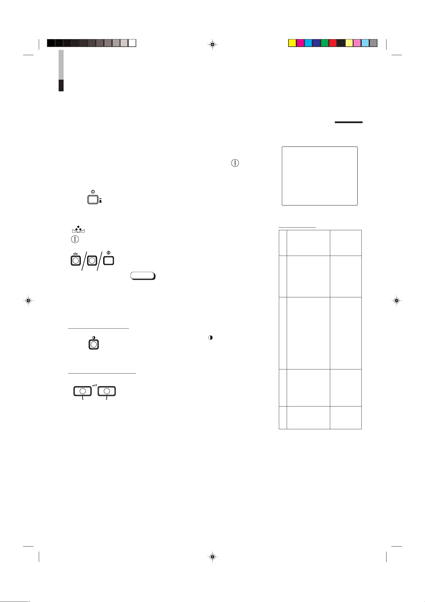
INICIALIZACION DEL AJUSTE
PHASE MENU
POWER
_ON
—OFF
CONTRAST
VOLUME/SELECT
– +
POWER
ON
OFF
INDICACION EN PANTALLA Y SELECCIONES EN
EL MODO DE REPOSICION <SET-UP MENU>
Usted puede ajustar los ítemes de pantalla <MENU> y <SET-UP MENU>, ajustar los
ítemes de imagen y el nivel de volumen a sus valores iniciales (ajustes de fábrica).
1. Presione el conmutador de alimentación ( ) para
—
ajustar la alimentación en OFF (
).
2. Mantenga presionado el botón de MENU y PHASE
( ) y presione el conmutador de alimentación
( ) para conectar (ON) (_) la alimentación.
Aparecerá la pantalla <SET-UP MENU> RESET.
Nota:
● La pantalla <SET-UP MENU> RESET no aparecerá si
presiona los botones MENU y PHASE durante un corto
tiempo. Manténgalos presionados hasta que aparezca
la pantalla de indicación.
3. Ajuste
Es necesario inicializar.
Presione el botón CONTRAST ( ).
* Cuando termine la inicialización desaparecerá la
pantalla <SET-UP MENU> RESET.
No es necesario inicializar.
Presione el botón VOLUME/SELECT [+] o [–].
* La inicialización es cancelada y desaparece la pantalla
<SET-UP MENU> RESET.
Pantalla <SET-UP MENU> RESET
<SET–UP MENU> RESET
Are you sure ?
“Yes ” then <CONTRAST>
“No” then <+> or <–>
Ajustes iniciales
Funciones
(ítemes)
Clasificación
SHARPNESS 00
COLOR TEMP. 6500
COLOR SYSTEM
ASPECT RATIO 4–3
BRIGHTNESS P.S.
Pantalla <MENU>
H. POSITION 00
V. POSITION 00
WHITE BALANCE
R. CUT OFF 00
G. CUT OFF 00
B. CUT OFF 00
R. DRIVE 00
G. DRIVE 00
B. DRIVE 00
CONTROL LOCK OFF
Pantalla <SET-UP MENU>
B.P.S. LEVEL 10
REMOTE SELECT OFF
PHASE 00
CHROMA 00
CONTRAST 00
BRIGHT 00
Ajuste de imagen
Inicialización
(ajuste)
AUTO
OFF
10
LCT0053-002A-H (SP) 02.07.30, 3:02 PM10
VOLUME
Volumen
20
Page 77

EJEMPLO DE CONEXION BASICA
Monitor de video
TM-2100PN
<secundario>
VCR
REMOTE
(cable remote)
VCR
Monitor de video
Videocámera
(cable de señal de audio)
Audio
Video
(cable de señal de video)
: Flujo de señal
Audio
Video
(cable de señal de video)
(cable de señal de audio)
REMOTE
(cable remote)
OUTIN
A
B
VIDEO
A
B
AUDIO
REMOTE
OUTIN
OUT
IN
OUT
IN
IN
OUT
Y/ C
OUT
IN
TM-2100PN
PHASECHROMA BRIGHT CONTRAST MENU
INPUT SELECT
VOLUME/SELECT
– +
BA
POWER
_ON
—OFF
Y/ C VIDEO VIDEO
Notas:
• Antes de conectar su sistema asegúrese de que todas las unidades estén desconectadas.
• La ilustración de abajo muestra algunos ejemplos de diferentes conexiones.
Las conexiones de terminales pueden diferir dependiendo del componente conectado.
Asegúrese de referirse a las instrucciones suministradas con la unidad/des que está conectando.
• Cada para de terminales de entrada (IN) y de salida (OUT) están conectados en puente.
• Si no está conectando ningún equipo a un terminal de salida (OUT) en puente, asegúrese de no conectar ningún otro cable al
terminal de salida (OUT) en puente ya que ello hará que el interruptor de resistencia de terminación se abra (función de
terminación automática).
• Cuando efectúe una conexión en puente, conecte los terminales de entrada (IN) y los de salida (OUT) en el monitor, a
componentes de video independientes.
(Por ejemplo, si conecta ambos terminales al mismo VCR, puede haber resonancia exceptuando la reproducción. La misma es
causada por el “looping” de la misma señal de video entre los VCR, y no es una falla).
• Seleccione la entrada de video (INPUT A (VIDEO), INPUT B (VIDEO) o INUT B (Y/C)) con los botones INPUT SELECT del
panel frontal.
• La función ASPECT RATIO o BRIGHTNESS P.S. puede ser controlada a través del terminal REMOTE. Para ésto, ajuste
REMOTE SELECT al modo <SET-UP MENU> (Consulte las páginas 8 y 9).
Ejemplo de conexión VIDEO A (Seleccione el botón de entrada A (VIDEO))
Conmutador de control externo
Funciones de
control externo
ASPECT RATIO 4–3 (4:3) 16–9 (16:9)
BRIGHTNESS P.S. OFF ON
Circuito abierto
(abierto)
Cortocircuito (corto)
Conmutador de control externo
Circuito abierto Cortocircuito
(abierto) (corto)
Clavija RCA
ESPAÑOL
11
LCT0053-002A-H (SP) 02.07.30, 3:02 PM11
Page 78
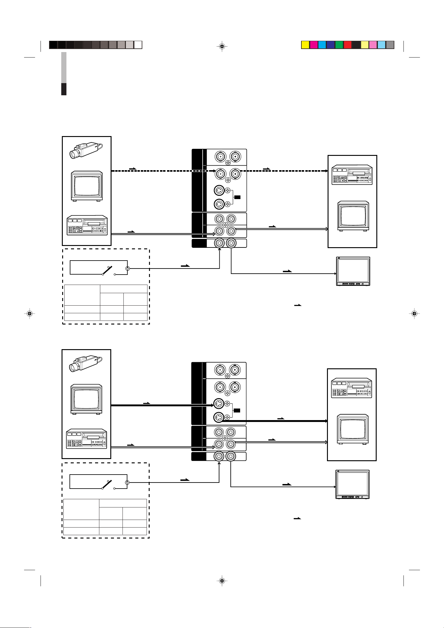
EJEMPLO DE CONEXION BASICA
Monitor de video
TM-2100PN
<secundario>
VCR
VCR
Monitor de video
Videocámera
(cable de señal de audio)
Audio
: Flujo de señal
Audio
Video
(cable de señal de video)
(cable de señal de audio)
REMOTE
(cable remote)
OUTIN
A
B
VIDEO
A
B
AUDIO
REMOTE
OUTIN
OUT
IN
OUT
IN
IN
OUT
Y/ C
OUT
IN
Video
(cable de señal de video)
REMOTE
(cable remote)
TM-2100PN
PHASECHROMA BRIGHT CONTRAST MENU
INPUT SELECT
VOLUME/SELECT
– +
BA
POWER
_ON
—OFF
Y/ C VIDEO VIDEO
Monitor de video
TM-2100PN
<secundario>
VCR
VCR
Monitor de video
Videocámara
(cable de señal de audio)
Audio
: Flujo de señal
Audio
(cable de señal de audio)
REMOTE
(cable remote)
OUTIN
A
B
VIDEO
A
B
AUDIO
REMOTE
OUTIN
OUT
IN
OUT
IN
IN
OUT
Y/ C
OUT
IN
Y/C (S-Video)
(cable de señal Y/C (S-Video))
Y/C (S-Video)
(cable de señal Y/C (S-Video))
REMOTE
(cable remote)
TM-2100PN
PHASECHROMA BRIGHT CONTRAST MENU
INPUT SELECT
VOLUME/SELECT
– +
BA
POWER
_ON
—OFF
Y/ C VIDEO VIDEO
(cont.)
Ejemplo de conexión VIDEO B (VIDEO) (Seleccione el botón de entrada B (VIDEO))
Conmutador de control externo
Circuito abierto
(abierto)
Cortocircuito (corto)
Funciones de
control externo
Conmutador de control externo
Circuito abierto Cortocircuito
(abierto) (corto)
ASPECT RATIO 4–3 (4:3) 16–9 (16:9)
BRIGHTNESS P.S. OFF ON
Clavija RCA
Ejemplo de conexión VIDEO B (Y-C) (Seleccione el botón de entrada B (Y/C))
Conmutador de control externo
Funciones de
control externo
Circuito abierto
(abierto)
Cortocircuito (corto)
Conmutador de control externo
Circuito abierto Cortocircuito
(abierto) (corto)
ASPECT RATIO 4–3 (4:3) 16–9 (16:9)
BRIGHTNESS P.S. OFF ON
Clavija RCA
12
LCT0053-002A-H (SP) 02.07.30, 3:03 PM12
Page 79

LOCALIZACION DE AVERIAS
Aquí se describen las soluciones para problemas comunes relacionados a su monitor.
Si ninguna de las soluciones aquí expuestas soluciona el problema, desenchufe el monitor y consulte a un agente
autorizado de JVC o al centro de servicio.
Problemas
No hay alimentación.
No hay imagen con la
alimentación
conectada.
No hay sonido.
La imagen fluctúa.
Sin colores, colores
equivocados o
fotografías oscuras.
La imagen no es
natural, el color de la
misma es irregular o
la.
En la parte superior e
inferior de la pantalla
aparecen bandas
negras, reduciendo la
imagen
verticalmente.
La porción del pico
del blanco de la
imagen (por ejemplo,
la parte encendida de
una lámpara
fluorescente) está
oscura, imprecisa y
el color es borroso.
El botón del panel
frontal no funciona.
Puntos a inspeccionar
¿Está el enchufe de alimentación flojo o
desconectado?
¿Sale señal de video del componente
conectado?
¿Fue correctamente seleccionada la señal de
entrada?
¿Está el cable de video desconectado?
¿Sale señal de audio del componente
conectado?
¿Está la salida de volumen ajustada al mínimo?
¿Está el cable de audio desconectado?
¿Está el monitor cerca de un dispositivo que
genera fuertes campos magnéticos?
¿Fue correctamente seleccionado el sistema de
color?
¿Ha modificado el ajuste de control de imagen
(CONTRAST, BRIGHT, CHROMA o PHASE)?
¿Está el monitor cerca de un altavoz, imán o
cualquier otro dispositivo que genere un fuerte
campo magnético?
¿Está la relación de imagen ajustada en 16:9 ?
¿Está la función BRIGHTNESS P.S. ajustada
en ON?
¿Están los botones de operación del panel
frontal bloqueados? (¿Está la función CONTROL LOCK ajustada en ON?)
Medidas
Inserte firmemente el enchufe de alimentación.
Ajuste correctamente el componente conectado.
Seleccione la entrada de señal de video
necesaria con el botón de selección de entrada.
(Ver página 6.)
Conecta firmemente el cable de sñal de video.
(Ver páginas 11 y 12.)
Ajuste correctamente el componente conectado.
Ajuste el volumen del altavoz con el botõn
VOLUME/SELECT. (Ver página 6.)
Conecta firmemente el cable de señal de audio.
(Ver páginas 11 y 12.)
Aleje el dispositivo del monitor hasta que la
imagen se estabilice.
Ajuste COLOR SYSTEM en el modo de pantalla
<MENU> al modo [AUTO] (Consulte la página 7).
Ajuste cada control de imagen en el estándar.
(Ver página 6.)
Aleje el dispositivo del monitor y desconecte la
alimentación del monitor. Espere 30 minutos
como mínimo, y conecte otra vez la alimentación.
Ajuste ASPECT RATIO en el modo de pantalla
<MENU> a [4:3 (4-3)] (Consulte la página 7).
Cuando realice el control externamente, ASPECT
RATIO debe estar ajustado en [4:3 (4-3)]
(Consulte las páginas 11 y 12).
Ajuste la función BRIGHTNESS P.S. en el modo
de pantalla <MENU> para OFF (Consulte la
página 7). Cuando realice el control
externamente, la función BRIGHTNESS P.S.
debe estar ajustada en OFF (Consulte las
páginas 11 y 12).
Ajuste CONTROL LOCK en OFF en el modo de
pantalla <SET-UP MENU> (Consulte las páginas
8 y 9).
Las siguientes no son fallas:
● Si se proyecta una imagen fija brillante (ej.: paño blanco) durante largo tiempo, la misma puede aparecer en color. Esto se debe
a la estructura del tubo de rayos catódicos y se borrará cuando se proyecte otra imagen.
● Si usted experimenta un choque eléctrico suave cuando toca el tubo de imagen. Este fenómeno es debido a la acumulación
normal de electricidad estática en el TRC y no es pernicioso.
● El monitor emite un sonido extraño cuando cambia rápidamente la temperatura de la sala. Esto sólo es problema si se verifica
alguna anormalidad en la pantalla también.
LCT0053-002A-H (SP) 02.07.30, 3:03 PM13
ESPAÑOL
13
Page 80

ESPECIFICACIONES
MODELO TM-2100PN
Tipo Monitor de video a color
Sistema de color PAL, NTSC (3,58)
Tubo de imagen 54 cm medidos diagonalmente, tipo cuadrado, plano, deflexión de 90°,
cañón en línea, tipo triple línea vertical
(la separación entre bandas de fósforo es de 0,69 mm)
Tamaño efectivo de la pantalla Ancho 406,4 mm
Altura 304,8 mm
Diagonal 508 mm
Frecuencia de barrido (H) 15,734 kHz (NTSC) 15,625 kHz (PAL)
(V) 59,94 Hz (NTSC) 50 Hz (PAL)
Resolución horizontal 450 líneas de TV o más (modo de entrada Y/C)
Terminales de entrada VIDEO A Video compuesto: 1 línea, conector BNC x 2,
1 V(p-p), 75 Ω, sincronización negativa
(conexión en puente posible, terminación automática)
VIDEO B Video compuesto: 1 línea, conector BNC x 2,
1 V(p-p), 75 Ω, sincronización negativa
(conexión en puente posible, terminación automática)
Y/C independientes: 1 línea, conector mini DIN de 4 clavijas x 2
Y: 1 V(p-p), 75 Ω
C: 0,286 V(p-p), 75 Ω (NTSC)/0,3 V(p-p), 75 Ω (PAL)
(conexión en puente posible, terminación automática)
AUDIO A 1 línea (monofónico), clavija RCA x 2
0,5 V(rms), alta impedancia
(conexión en puente posible)
AUDIO B 1 línea (monofónico), clavija RCA x 2
0,5 V(rms), alta impedancia
(conexión en puente posible)
REMOTE 1 línea, 2 pins RCA (Conexión en puente posible)
Salida de potencia de audio 1 W (monofónico)
Altavoz incorporado Redondo de 8 cm x 1
Impedancia de 8 Ω
Condiciones ambientales Temperatura de funcionamiento: 0 °C – 40 °C
Humedad de funcionamiento: 20 % – 80 % (sin condensación)
Requisitos de alimentación 230 V CA, 50 Hz/60 Hz
Consumo de energía 0,72 A (230 V CA)
Dimensiones Ancho 476 mm
Altura 407,5 mm
Profundidad 492 mm
Peso 28,5 kg
Accesorio Cordón de alimentación de CA (2 m) x 1
* Las ilustraciones empleadas en este manual sólo sirven como explicación. El aspecto del producto real puede diferir levemente.
* Las dimensiones y los pesos son aproximados.
* E. & O.E. El diseño y las especificaciones están sujetos a cambio sin aviso.
14
LCT0053-002A-H (SP) 02.07.30, 3:03 PM14
Page 81

416,4
*
476
382,8
314,8
*
407,5
TM-2100PN
PHASE CHROMA BRIGHT
CONTRAST
MENU
INPUT SELECT
VOLUME/SELECT
– +
BA
POWER
ON
OFF
Y/ C VIDEO VIDEO
Dimensiones
4
2
3
4
3
1
2
1
OUT
IN
Y/C
4791,3 9,5
105
492
135 128,5
50,2
3,5
Unidad: mm
< Vista frontal >
* Los asteriscos (*) son empleados para indicar las
dimensiones del panel frontal.
< Vista lateral >
Disposisión de las clavijas del
terminal Y/C
No. de Señal
clavija
1 MASA (Y)
2 MASA (C)
3Y
4C
LCT0053-002A-H (SP) 02.07.30, 3:03 PM15
ESPAÑOL
15
Page 82

MEMO
MENO
MENO
LCT0053-002A-H (EN) 02.07.30, 2:46 PM16
Page 83

MENO
MENO
MEMO
LCT0053-002A-H (EN) 02.07.30, 2:46 PM17
Page 84

TM-2100PN COLOUR VIDEO MONITOR
2002 VICTOR COMPANY OF JAPAN, LIMITED
©
ï /ï /îí 02.07.30, 3:23 PM2
VICTOR COMPANY OF JAPAN, LIMITED
Printed in Thailand
0702-Y-U-JMT
 Loading...