

Page 1
COLOR VIDEO CAMERA
TK-WD9602E
Thank you for purchasing this product.
Before operating this unit, please read the instructions carefully to ensure the
best possible performance.
How to Read This Manual
Conventions and symbols
: Indicates operating precautions.
: Indicates reference data regarding limitations on functions,
usage and the like.
: Indicates a reference page or item.
Contents of this manual
• Our company holds the copyright to this manual. Any part or all of this
manual may not be reproduced without prior consent from the company.
• Product names of other companies described in this manual are
trademarks or registered trademarks of the respective companies.
Symbols such as ™, ®, and © are omitted in this manual.
• Design, specifications and other contents described in this manual are
subject to change for improvements without prior notice.
INSTRUCTIONS
LST1552-001A
Safety Precautions
CAUTION
To prevent electric shock, do not open the cabinet.
No user serviceable parts inside. Refer servicing to qualified service
personnel.
Dear Customer
This apparatus is in conformance with the valid European directives and
standards regarding electromagnetic compatibility and electrical safety.
European representative of JVC KENWOOD Corporation is:
JVC Technical Services Europe GmbH
Konrad-Adenauer-Allee 1-11
61118 Bad Vilbel
Germany
Sehr geehrter Kunde, sehr geehrte Kundin,
dieses Gerät stimmt mit den gültigen europäischen Richtlinien und
Normen bezüglich elektromagnetischer Verträglichkeit und elektrischer
Sicherheit überein.
Die europäische Vertretung für die JVC KENWOOD Corporation ist:
JVC Technical Services Europe GmbH
Konrad-Adenauer-Allee 1-11
61118 Bad Vilbel
Deutschland
● The unit is to be powered by a DC 12 V or an AC 24 V power supply.
● The AC 24 V and DC 12 V power supply shall conform to the following:
Isolated power supply only.
● This installation should be made by a qualified service person and should
conform to all local codes.
● Special technique is required when installing this product.
Please refer to the nearest dealer for installation.
● Rating label is pasted on of the camera unit.
● JVC is not liable for any compensation if you drop the camera due to
insecure mounting by not following the installation description. Pay careful
attention during installation.
● When mounting this product to a ceiling or wall, select a location strong
enough to support the weight of this camera. If the location is not strong
enough to support the weight, be sure to reinforce the ceiling or wall
before installation.
● The camera may drop if the mounting screws are not tightened securely.
Check that the screws are tightened appropriately and securely.
● Do not install the camera near lighting fixtures of high temperature, such as
spot lights. It might result in failure or fires.
● Do not hang on this product, shake it, or hang objects over it. Applying an
excessive load may cause the product to fall off and result in accidents.
Operating Precautions
■ Storage and Location of Use
● Do not install the camera in the following places.
• In a place exposed to rain or moisture.
• In a place with vapor or oil, for example in a kitchen.
• When the ambient temperature rises above or falls below the acceptable
range (from -10 °C to 50 °C)
• In a place at which corrosive gases are emitted.
• Near a source of radiation, X-rays, strong radio waves or magnetism.
• In a place subject to vibration.
• In a place with excessive dirt.
● Using this unit in the vicinity of the transmitting antenna of a radio or TV,
devices that emit strong electromagnetic waves such as a transformer or
motor, or wireless devices such as a transistor or mobile phone may give
rise to noises in the image and changes in its colour.
● This camera has been designed for indoor use. When using it outdoors, it
is necessary to use an outdoor camera housing (optional).
■ Maintenance
● Wipe the camera with a dry, soft cloth to remove any dirt.
Do not use benzene or thinner to wipe the camera. Doing so may melt the
surface or cause it to fog. For tough stains, wipe with a neutral detergent
diluted with water, followed by wiping with a dry cloth.
■ Energy Conservation
● When the camera is not in use for a long time, turn off the power for
safety and energy conservation reasons.
■ Copyright Protection
● With the exception of the user being the copyright holder or when
permission such as for duplication has been granted by the copyright
holder, permission is required in principle for the duplication, modification,
or transmission of copyrighted material.
● Unauthorized duplication, modification, or transmission of copyrighted
material may constitute a copyright infringement, and the user may be
liable to compensate for any damages. When using copyrighted material,
be sure to check the license agreement of the copyrighted material
thoroughly.
● When rights or rights holders are involved with regard to the targeted
duplicating subject, permission may be required for shooting or using
(processing) it. Be sure to check the licensing conditions thoroughly.
■ Disclaimer
● We will not be responsible for any inconveniences or disturbances caused
in the event of privacy invasion as a result of camera footages of this
product.
■ Others
● Under fluorescent lights and the like, the hue of the bright areas of the
screen may change periodically. If this happens, set [CRR MODE] to “ON”
to reduce this phenomenon.
● When the [AGC/SHUTTER] setting is anything except “OFF”, the
sensitivity increases automatically for dark images and the screen may
appear grainy, but this is not a malfunction.
● When the [AGC/SHUTTER] setting is “×2”, “×4”, “×8”, or “×16” and [WDR
LEVEL] is set to the plus side, the camera exposure may not emulate the
subject. If this happens, set [AGC/SHUTTER] to “LOW”, “MID”, or “HIGH”,
or lower the [WDR LEVEL] to near “NORMAL” to use it.
● When [EASY D/N] is set to “AUTO”, the image turns black-and-white in a
dark location. As the sensitivity level is increased in this case, the screen
may appear grainy and more white spots may appear. When switching
between modes, the brighter area on the screen is emphasized and
visibility may be reduced. However, this is not a malfunction.
● Before mounting the camera to the mounting location, attach the lens to
be used on the camera and check the back focus.
● When the white balance of this camera is set to “ATW-W”, “ATW”, or
“ATW-I” and depending on the conditions of the object, the colour tone
may differ slightly from the actual colour due to the principle of the
automatic tracking white balance circuit. This is not a malfunction.
● When this camera is moved from a cold to warm place, condensation may
occur and the camera may not work. In this case, leave the camera under
room temperature for about one hour before turning on the power.
● When the power supply voltage is momentarily disrupted or drops due
to lightning, turning on the air-conditioner or the like, image distortion or
noise may occur.
● The 3D noise reduction function of this camera may result in afterimage
of a moving subject. Afterimage is more likely to occur when using the
camera with [DNR MODE] set to anything except “OFF”. This is not a
malfunction.
● Noise may be more visible in dark areas of images if subjects are in low
lighting, brightness changes drastically, or if there is extreme backlighting,
but this is not a malfunction.
• Always do a test recording in advance, to make sure that important
images are being recorded correctly.
• Understand that no compensation is provided for information that is not
recorded because of any problem with the video camera or recording
equipment.
Connections and Installation
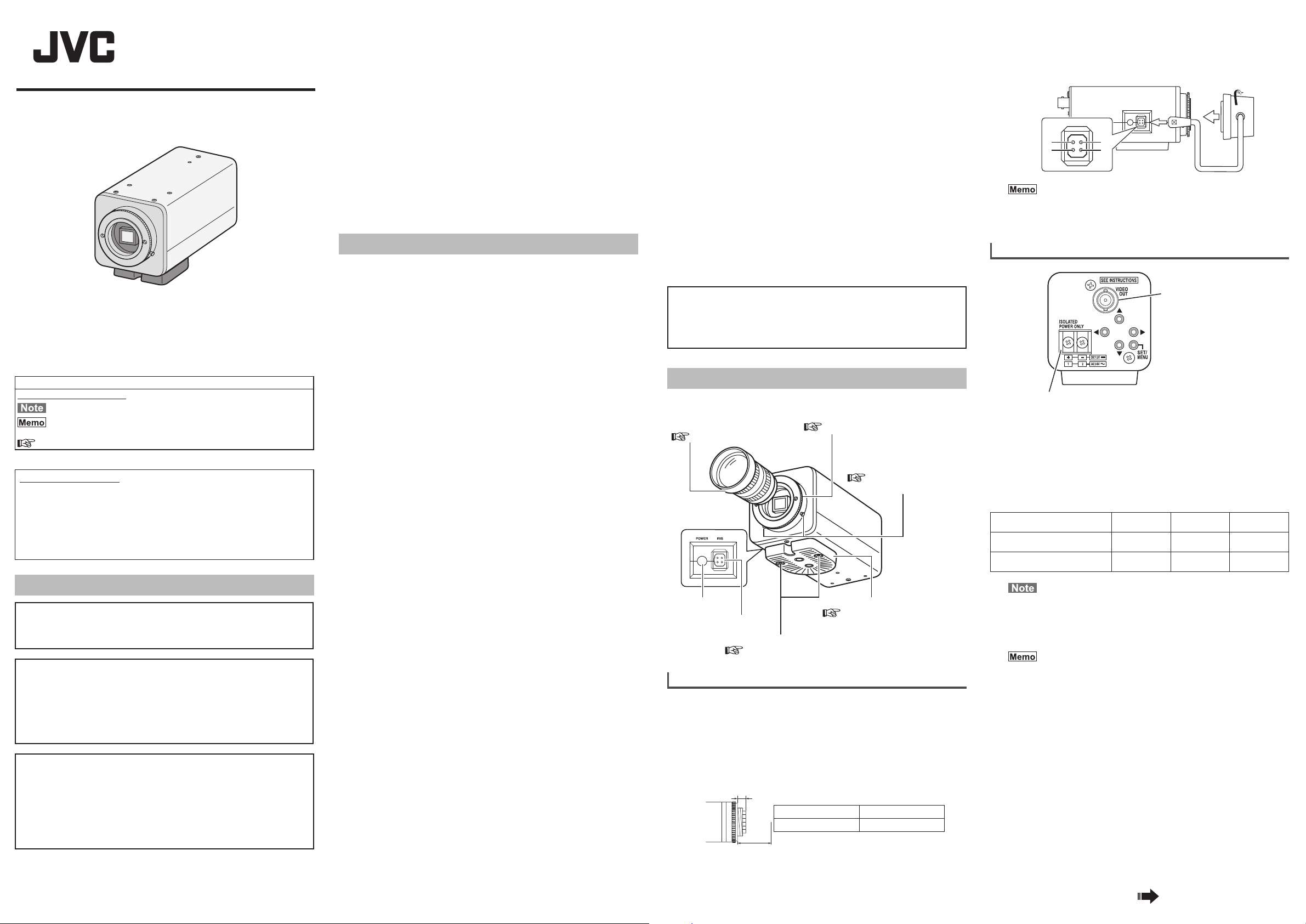
Follow the procedures for connections and installation to use the product.
CS mount lens
(sold separately)
“Mounting Lenses” P.1
Power lamp
IRIS terminal
Camera mounting bracket fastening screw
“Mounting the Camera on a Fixer or Pan/tilt Unit” P.2
Mounting Lenses
1 Confirm the mounting system of lenses you are using
before you mount them.
• The product supports CS mount lenses.
• To use C-mount lenses, you need a C-mount adapter. Contact the
nearest dealer for information about C-mounts.
Do not use lenses with a long (a) dimension, as shown in the figure
below, they cannot be mounted correctly and will damage the inside of
the camera. Doing so causes malfunctions.
(a)
(b)
2 Turn the lens clockwise and mount it firmly on the
camera.
Back focus adjustment ring
“Adjusting the Back Focus” P.2
Back focus fastening screw
“Adjusting the Back
Focus” P.2
Camera mounting bracket
“Mounting the Camera on a
Fixer or Pan/tilt Unit” P.2
Flange focus (b) Dimension (a)
12.5 mm 5.5 mm or less
■ For DC iris lenses
Confirm the layout of the pins and connect the lens
3
cable to the IRIS terminal.
2
POWER IRIS
1
2
• You cannot use a video iris lens.
• If the lens cable plug does not match, use a 4-pin plug.
[4-pin plug part number: SCV2859-001]
The 4-pin plug is available from the nearest dealer.
3
4
3
Connecting Various Cables
VIDEO OUT terminal
AC 24 V, DC 12 V power input terminal
■ Connecting the Power Supply Cable
When power is supplied to the camera, the POWER lamp on the side panel
lights up.
● AC 24 V or DC 12 V
To prevent connection errors or a cable disconnection, use a lug plate to
connect to the terminal.
The following table shows the connection distances when 2-core VVF (vinylinsulated vinyl sheath cables) are used. (Reference value)
Conductor diameter
(mm)
Maximum connection
distance: DC 12 V
Maximum connection
distance: AC 24 V
• Do not connect an AC 24 V cable to a commercial power
supply. If it is connected by mistake, the internal circuit may
be damaged. Send the camera to the nearest dealer for
inspection as the internal circuit may be damaged.
• Do not connect DC 12 V and AC 24 V cables at the same
time.
• If thin cables are used, the resistance of the cables will
be high and a significant voltage drop will occur when the
camera is at its maximum power consumption. Either use
a thick cable with low resistance or place the power supply
near to the camera and shorten the length of the cable to
restrict the voltage drop at the rated current of camera to
below 10%. If voltage drop occurs during operation, the
performance will be unstable.
• When using a DC 12 V power supply, ensure that the
polarities of the cable are correct.
• For safety reasons, turn on the power only after ensuring
that all the connections are in place.
■ Connecting the Monitor
Connect with a 75 Ω coaxial cable (BNC) such as RG-59 or equivalent.
Φ 1.0 and
more
50 m 140 m 220 m
130 m 350 m 550 m
Φ 1.6 and
more
Continued on back
Φ 2.0 and
more
1
Page 2
BF
LOCK
BF
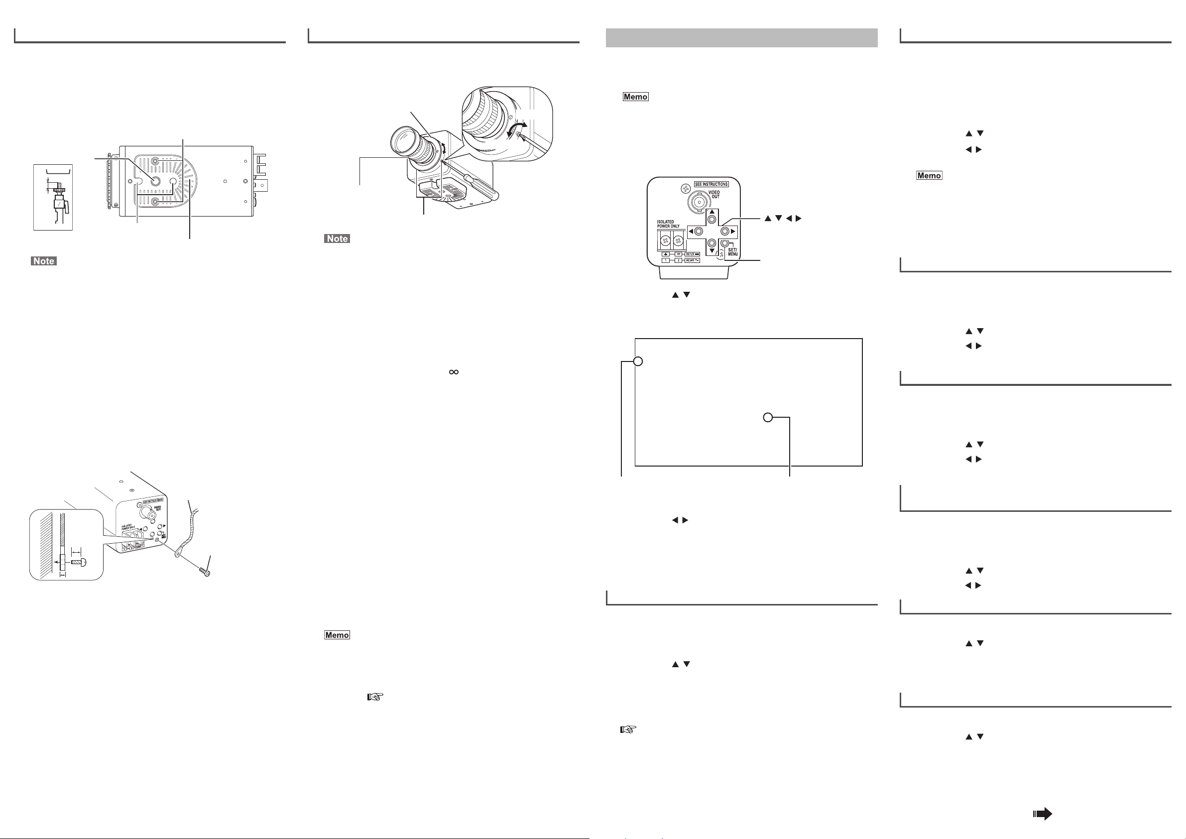
Mounting the Camera on a Fixer or Pan/tilt Unit
● Use the camera mounting screw hole on the camera mounting bracket to
mount the camera. (screw is less than 7 mm long)
● The camera mounting bracket is originally mounted at the bottom of the
camera before shipment.
When mounting the bracket on top of the camera, remove the two
fastening screws from the camera mounting bracket and reattach it.
Fasten the screws securely.
Camera mounting bracket fastening screws
Camera mounting
screw hole
MAX.
7mm
Rotation-preventive hole
• Use camera mounting screws that extend less than 7 mm
past the mounting surface. Use camera mounting bracket
fastening screws that are less than 6 mm long. Do not use
screws that are longer than specified. Doing so could cause
interior damage.
• Always wear protective eyewear to protect your eyes from
falling objects when doing ceiling mounts.
■ Precautions about the Camera Falling
● Special precautions are needed when mounting the camera on a wall or
ceiling. Use professional technicians for this, do not do it yourself. The
camera could cause injury or damage if it falls.
● If the camera is mounted on a fixer, pan/tilt unit and the like, use a
rotation-preventive hole to prevent falling and attach it securely.
● To prevent fall, connect the camera to a section with sufficient strength
(ceiling slab or channel) using a fall prevention wire.
● Also, carefully consider the length, strength, layout, material (insulation),
and other aspects of the fall prevention wire.
● Use the screws (M3 × 6 mm) on the back of the product to attach the fall
prevention wire. Do not use screws that are longer than 6 mm, doing so
may damage the inside of the camera.
6mm
6 mm
2 mm
(2 pcs: M 2.6 x 6 mm)
Camera mounting bracket
Fall prevention wire
Screws (M3 x 6 mm)
Adjusting the Back Focus
This camera is adjusted to an optimum wide range before shipment but
readjustment is required when using zoom lens or when the lens focus ring
is out of focus.
Back focus adjustment ring
Loosen
BF
LOCK
BF
LOCK
Focus ring on lens
Back focus fastening screw (2 locations)
Note that if the back focus fastening screw is too loose, it will
come off.
■ For Fixed-Focus Lens
If the focus cannot be adjusted correctly with the lens focus ring, adjust the
back focus as follows.
1 Use a Phillips head screwdriver to turn the back focus
fastening screws (2 screws) counterclockwise to
loosen them.
2 Shoot some fine patterns on the subject or away from
the subject.
3 Turn the lens focus ring to .
4 Rotate the back focus adjustment ring to the best
focus.
5 Turn the back focus fastening screws (2 screws)
clockwise to tighten and fix them securely.
■ For Zoom Lens
If the image is out of focus when zooming (telephoto – wide angle), adjust
the camera as follows.
1 Use a Phillips head screwdriver to turn the back focus
fastening screws (2 screws) counterclockwise to
loosen them.
2 Shoot some fine patterns on the subject or away from
the subject.
3 Zoom to the maximum telephoto position and turn the
lens focus ring to adjust the focus.
4 Zoom to the maximum wide angle position and turn
the back focus adjustment ring to adjust the focus.
5 Repeat steps 3 and 4 two or three times.
6 Turn the back focus fastening screws (2 screws)
clockwise to tighten and fix them securely.
• If the lens cable is not long enough when you are rotating
the back focus adjustment ring, temporarily tighten the back
focus fastening screws, and then loosen the back focus
fastening screws again after rotating the lens and then readjust the back focus.
• Adjusting the focus becomes easier in the [FOCUS
ADJUST] mode.
See “Finely Adjusting the Focus (FOCUS ADJUST)”
P. 2
• When the subject is bright and an ND filter is used, back
focus adjustment can be performed more accurately. (An ND
filter is a filter that reduces light incident on the lens of all
wavelengths equally.)
Tighten
Menu Settings
This section explains how to do settings on the menus and some basic
settings. Do the various settings as necessary.
Refer to “List of Menu Items” and “Menu Details” (P.3) for details about the
menu settings.
Do not turn off the power while a menu is displayed. If this is
done, the settings may not be saved.
■ How to Do Menu Settings
This procedure is for some basic menu settings.
1 Press the [SET/MENU] button for at least two seconds.
The [MENU] screen appears on the monitor.
[
/ / / ] buttons
[SET/MENU] button
2 Press the [ / ] buttons to move the cursor (>) on the
[MENU] screen to the desired item.
• For items that have sub-menus (items that end with ..), press the [SET/
MENU] button to open the sub menu screen.
- - - M E N U - - -
> F O C U S A D J U S T ..
W D R L E V E L N O R M A L
B R I G H T N E S S N O R M A L
C O N T R A S T N O R M A L
E A S Y D / N A U T O
V I D E O A D J U S T ..
C A M S E T T I N G S ..
E X I T
Cursor Indicates a sub-menu exists
3 Press the [ / ] buttons to change the set values.
It may take a long time to apply the settings on the menu that is
displayed by pressing and holding these buttons.
4 When you have finished doing the settings, select
[EXIT] on the [MENU] screen, and press the [SET/MENU]
button to exit the menu mode.
Finely Adjusting the Focus (FOCUS ADJUST)
Adjusting the focus of a DC iris lens is easier in the [FOCUS ADJUST] mode.
In the [FOCUS ADJUST] mode the iris is forced open and the subject's depth
of field is shallow. (Look at the instruction manual of the lens also.)
1 Press the [SET/MENU] button for at least two seconds.
2 Press the [ / ] buttons to select [FOCUS ADJUST..],
then press the [SET/MENU] button.
The [FOCUS ADJUST] screen appears.
3 Adjust the focus of the lens.
If you cannot focus the lens by adjusting the focus of the lens, you need
to adjust the back focus.
“Adjusting the Back Focus” P.2
4 When you have finished the adjustment, select [EXIT]
in the [MENU] screen and press the [SET/MENU]
button to exit the menu mode.
Press the [SET/MENU] button to
open sub-menu.
Setting Backlight Compensation (WDR LEVEL)
This section describes how to set the wide dynamic range (WDR) function.
Set it according to conditions in bright areas (back lighted) such as in
sunlight.
Increase the value if there is a large difference in light and dark areas. The
dark areas will be easier to see.
Reduce the WDR level value if the image is bright and there is a small
difference in light and dark areas.
1 Press the [SET/MENU] button for at least two seconds.
2 Press the [ / ] buttons to select [WDR LEVEL].
3 Press the [ / ] buttons to select from “-10” to
“NORMAL” to “10”.
• The wide dynamic range function makes it possible to clearly
and naturally see subjects of widely varying brightness in
the same screen, even when shooting situations with a
large difference in brightness (near windows and doors that
are easily affected by exposure to the afternoon sun and
backlighting).
• Verify the WDR level in the environment in which the camera
will be operating before setting it.
Setting the Brightness of the Image (BRIGHTNESS)
This section describes how to set the brightness of the entire image.
Increase the value to make the entire image brighter, reduce the value to
make the entire image darker.
1 Press the [SET/MENU] button for at least two seconds.
2 Press the [ / ] buttons to select [BRIGHTNESS].
3 Press the [ / ] buttons to select from “-10” to
“NORMAL” to “10”.
Setting the Contrast of the Image (CONTRAST)
This section describes how to set the contrast of the entire image. Increase
the value to increase contrast in dark areas, reduce the value to decrease
contrast.
1 Press the [SET/MENU] button for at least two seconds.
2 Press the [ / ] buttons to select [CONTRAST].
3 Press the [ / ] buttons to select from “-10” to
“NORMAL” to “10”.
Setting Automatic Change from Colour to
Black and White (EASY D/N)
Set “AUTO” to continuously shoot subjects in brightness that varies from day
to night. When it is bright, images are in colour. When it is dark, images are in
black and white.
1 Press the [SET/MENU] button for at least two seconds.
2 Press the [ / ] buttons to select [EASY D/N].
3 Press the [ / ] buttons to select “OFF” or “AUTO”.
Setting the Quality of the Image (VIDEO ADJUST)
1 Press the [SET/MENU] button for at least two seconds.
2 Press the [ / ] buttons to select [VIDEO ADJUST..].
3 Press the [SET/MENU] button.
The [VIDEO ADJUST] screen appears.
Refer to “VIDEO ADJUST” (P.3-4) for details.
Setting the Camera (CAMERA SETTINGS)
1 Press the [SET/MENU] button for at least two seconds.
2 Press the [ / ] buttons to select [CAM SETTINGS..].
3 Press the [SET/MENU] button.
The [CAMERA SETTINGS] screen appears.
Refer to “CAMERA SETTINGS” (P.4) for details.
Continued on next page
2
Page 3

List of Menu Items
MENU
FOCUS ADJUST..
RETURN
WDR LEVEL
WDR CUSTOM SET
WDR PRIORITY
WDR BIAS
WDR LIMIT
EXP BIAS
RETURN
BRIGHTNESS
CONTRAST
EASY D/N
VIDEO ADJUST..
AGC/SHUTTER
WHITE BALANCE
MANUAL..
COLOUR LEVEL
ENHANCE LEVEL
RESOLUTION
DNR MODE
WDR AREA SET
RETURN
CAM SETTINGS..
LENS ADJUST..
DC GAIN
DC OFFSET
IRIS TH
RETURN
PROGRESSIVE
CRR MODE
CAMERA TITLE
TITLE EDIT
PRIVACY MASK..
MASK 1 to 4
RETURN
Menu Details
The setting in bold is the factory setting.
MENU
FOCUS ADJUST
Select this to adjust the focus of the DC iris lens. When [FOCUS ADJUST..]
is selected, the focus adjustment screen opens. Adjusting the focus is easier
because the iris is completely open and the depth of field is shallower.
RETURN
Returns to the [MENU] screen.
WDR LEVEL
For setting the wide dynamic range (WDR) function. Set it according to
conditions in bright areas (back lighted) such as in sunlight. Increase the
value if there is an extreme difference in light and dark areas to make the
dark areas easier to see, reduce the value if the image is bright and there is
a small difference in light and dark areas.
Setting: CUSTOM.., -10 to NORMAL to 10
• CUSTOM..: Manually adjust the wide dynamic range. Press the [SET/
WDR CUSTOM SET
WDR PRIORITY
Select whether the wide dynamic range gives priority to light areas or dark
areas.
Setting: LIGHTS, SHADOWS
• LIGHTS: Light areas are easier to see.
• SHADOWS: Dark areas are easier to see.
WDR BIAS
For setting the low to mid level brightness of the wide dynamic range.
If [WDR PRIORITY] is set to “LIGHTS”, increasing the value makes it
brighter, decreasing the value makes it darker. If [WDR PRIORITY] is set to
“SHADOWS”, the operation is the opposite of that for “LIGHTS”.
Setting: -36 to 0 to 36
WDR LIMIT
For setting the maximum of the wide dynamic range. Increase the value
when shooting a subject with large variations in light and dark, reduce the
value when shooting a subject with low variations in light and dark.
Setting: 0 to 30 to 36
EXP BIAS
For adjusting output characteristics in relation to the brightness level of the
subject. Increase the value to make dark subjects more clear, reduce the
value to make bright subjects more clear.
Setting: -18 to 0 to 18
RETURN
Returns to the [MENU] screen.
MENU] button to open the [WDR CUSTOM SET] screen.
Hunting may occur if the setting is greater than 15. If this
happens, lower the setting.
BRIGHTNESS
For setting the brightness of the entire image. Increase the value to make
the entire image brighter, reduce the value to make the entire image darker.
Setting: -10 to NORMAL to 10
Noise may become apparent as the setting increases.
CONTRAST
For setting the contrast of the image. Increase the value to increase contrast
in dark areas, reduce the value to decrease contrast.
Setting: -10 to NORMAL to 10
Increasing the contrast may improve the occurrence of noise in
the dark areas around bright areas.
EASY D/N
Set “AUTO” to continuously shoot subjects in brightness that varies from day
to night. When it is bright, images are in colour. When it is dark, images are
in black and white.
Setting: OFF, AUTO
You cannot use the “OFF” / “LOW” / “MID” setting for [AGC/
SHUTTER], if [EASY D/N] is set to “AUTO”.
VIDEO ADJUST
AGC/SHUTTER
Set whether AGC (Automatic Gain Control) automatically lengthens
exposure time, and increases sensitivity by several times, if a subject is
dark.
Setting: OFF, LOW, MID, HIGH, ×2, ×4, ×8, ×16
Settings and gain
Lower Higher
Gain
Setting
OFF
LOW
MID
HIGH
×
2
×
4
×
8
×
16
Example: Set to ×4
As a subject becomes darker, the gain increases and the screen becomes
brighter as digital sensitivity is increased ×2. As a subject becomes even
darker, the screen becomes brighter as digital sensitivity is increased ×4.
In this way, as a subject becomes even darker, the gain increases to the
maximum, and the screen becomes brighter.
*
When digital sensitivity is increased, sensitivity increases but works
unnaturally.
• When increasing the gain, noise will appear in the screen for
dark areas.
• You cannot use the “OFF” / “LOW” / “MID” setting, if [EASY D/N]
is set to “AUTO”.
• In dark areas if [AGC/SHUTTER] is set to “×2” or higher,
LOW
0dB
Sense up (slow shutter)
×2
×2
×2
×2
- The screen may temporarily lock up or noise and white spots
may become apparent.
- The entire screen may temporarily change from dark to bright.
- Particularly for dark areas, the Wide Dynamic Range (WDR)
function stops functioning.
×4
×4
×4
×8
×8
×16
WHITE BALANCE
You can set the white balance.
Setting: ATW-W, AT W, ATW-I, AWB·SET, MANUAL..
• ATW-W: Supports a wide range of colour temperatures (2500 K to
over 10000 K).
• ATW: Supports colour temperature of lighting (colour temperatures
from 3000 K to 8000 K) and automatically adjusts white
balance.
• ATW-I: Supports colour temperature of indoor lighting, mainly
fluorescent lights (3000 K to 5000 K) and automatically
adjusts white balance.
• AWB·SET: Press the [SET/MENU] button to automatically adjust and
preset the white balance.
• MANUAL..: Opens the [MANUAL W. BALANCE] screen.
MANUAL W. BALANCE
R-B For adjusting R (red) and B (blue) hues. The further the
setting is to the R side the stronger the reds become, the
further to the B side the stronger the blues become.
Setting: R to B
RETURN Returns to the [VIDEO ADJUST] screen.
COLOUR LEVEL
For adjusting the colour levels in the image signal. Increase the value to
make colours darker, reduce the value to make colours more pale.
Setting: -5 to NORMAL to 5
If a subject has very dark colours, some fuzzy noise may appear.
If this happens, lower the colour level setting.
ENHANCE LEVEL
For adjusting the edge enhancement to make the image sharper. Set it to
“HIGH” to make edges sharper, and set it to “LOW” to make edges softer.
Setting: LOW, MID, HIGH
The “HIGH” enhancement level is optimized to be effective in low
light.
RESOLUTION
Select a resolution mode to suit the operating environment.
Setting: NORMAL, HIGH, 16:9
• NORMAL: Aspect ratio 4:3
• HIGH: Aspect ratio 4:3/High resolution mode
• 16:9: Aspect ratio 16:9/High resolution mode
• Resolution will increase if “HIGH” or “16:9” is selected, but noise
may also become more apparent.
• Setting “HIGH” or “16:9” changes the angle of view, compared
to “NORMAL”.
DNR MODE
This mode reduces noise while shooting images. Setting this to “HIGH”
reduces image noise, but if the subject is moving, it may leave afterimages.
Setting: OFF, LOW, MID, HIGH
FLIP
FACTORY SETTING..
RETURN
EXIT
CANCEL
CLEAR
Continued on back
3
Page 4

WDR AREA SET
For selecting the photometry area.
Setting: NORMAL, AREA 1 to 4, CUSTOM..
• NORMAL: The entire screen becomes the photometry area.
• AREA1 to 4: Select from one of the following four photometry areas.
Photometry area
Area 1 Area 2 Area 3 Area 4
• CUSTOM..:
Light is measured in a specified area.
How to specify a photometry area (custom)
1) Each time the [SET/MENU] button is pressed the frame for setting
the area changes from white to green to red and back to white.
Adjust the frame as shown below to align the frame in the position
you want to be photometric.
● When the frame is white, use the [ / / / ] buttons to move the frame.
● When the frame is green, use the [
● When the frame is red, use the [
2) Press the [SET/MENU] button for at least two seconds to return to
the VIDEO ADJUST menu.
• The WDR area settings cannot be set to the very edge of the
screen.
• The WDR area cannot be set when [FLIP] of [CAMERA
SETTINGS] is “ON” and [- - -] is displayed. In this situation, the
WDR area functions as “NORMAL”.
• After setting the WDR area, if [FLIP] is turned on then off, the
WDR area setting changes to “NORMAL”.
• Note that the frame may change to white if there is a sudden
alteration to the brightness while the frame is green or red
during customization.
• Set the area after setting the [RESOLUTION] mode.
/ / / ] buttons to enlarge the frame.
/ / / ] buttons to reduce the frame.
RETURN
Returns to the [MENU] screen.
CAMERA SETTINGS
LENS ADJUST
Adjust this setting when you are using a DC iris lens.
LENS ADJUST
DC GAIN
DC OFFSET
IRIS TH
RETURN
PROGRESSIVE
Set this to “ON” if you want to clearly see a subject that is moving.
The camera operates in a shooting mode with no interlace noise when
the [PROGRESSIVE] setting is “ON”. It is especially effective with image
analysis applications.
Setting: OFF, ON
This is set when adjusting the operating speed of a DC
iris lens. Adjust this to suit the lens you are using. The
operating speed increases as the value increases.
Setting: 0 to 20 to 255
This sets the base level (brightness) used for controlling
the DC auto iris operation.
As the value increases the lens is stopped down, so the
image becomes darker.
Setting: 50 to 100 to 200 (CRR MODE: OFF)
50 to 120 to 200 (CRR MODE: ON)
This sets the gain threshold at which the DC auto iris
operates.
Hunting may occur if the setting is high. Normally, use the
factory setting.
Setting: -48 to -18 to 20 (CRR MODE: OFF)
-48 to -10 to 20 (CRR MODE: ON)
Returns to the [CAMERA SETTINGS] screen.
CRR MODE
For setting the Colour Rolling Reduction (CRR) function.
Under fluorescent lights and the like, the hue of the bright areas of the
screen may change periodically. If this happens, set [CRR MODE] to “ON”
to reduce this phenomenon.
Setting: OFF, ON
If it is not effective enough, adjust [DC OFFSET] under [LENS
ADJUST]. Increasing the value of [DC OFFSET] reduces this
phenomenon, but the image becomes darker. Adjust it to suit the
operating environment.
CAMERA TITLE
For setting the camera title display.
When it is set to “ON”, the title of the camera appears from the bottom left
of the screen, unless a menu is displayed.
Setting: OFF, ON
TITLE EDIT
For editing the camera title display. You can enter up to 20 characters for the
camera title.
How to edit the camera title
1) Press the [SET/MENU] button for at least two seconds.
2) Press the [ / ] buttons to select [CAM SETTINGS..], then press
the [SET/MENU] button.
The [CAMERA SETTINGS] screen appears.
3)
Press the [ / ] buttons to select [TITLE EDIT], then press the
[SET/MENU] button.
The cursor moves to below [TITLE EDIT].
4)
Press the [ / ] buttons to select characters, then press the [SET/
MENU] button.
When a character is decided, the cursor moves to the next character
position. To input more characters, repeat step 4).
Characters that can be input and the order they appear are shown below.
SP
0 1 2 3 4 5 6 7 8 9 A B C D E F G H I
J K L M N O P Q R S T U V W X Y Z a b c
d e f g h i j k l m n o p q r s t u v w
x y z + - . , ‘ : / ( ) < > “
5)
When you have finished entering text, press the [ / ] buttons to
exit camera title editing.
You can move the position where the camera title is displayed
from left to right by inserting spaces in front of the title in [TITLE
EDIT].
°
PRIVACY MASK
You can specify a portion of the live image that you intend to hide.
• You can set up to four locations to mask.
• In the screen for changing the privacy mask, only the masked
portions are shown.
• If the [CAMERA TITLE] setting is “ON”, the camera title display
area (20 characters) is not masked.
• Set the area after setting the [RESOLUTION] mode.
MASK
1 to 4
RETURN
This individuates the privacy masks with numbers for masks 1 to 4.
Setting: OFF, ON..
Returns to the [CAMERA SETTINGS] screen.
How to set the privacy mask
1) Press the [SET/MENU] button for at least two seconds.
2) Press the [ / ] buttons to select [CAM SETTINGS..], then press
the [SET/MENU] button.
The [CAMERA SETTINGS] screen appears.
3)
Press the [ / ] buttons to select [PRIVACY MASK..], then press
the [SET/MENU] button.
The [PRIVACY MASK] screen appears.
4)
Press the [ / ] buttons to select a mask number, press [ / ] to
select “ON..”, then press the [SET/MENU] button.
The mask appears white.
5) Press the [ / / / ] buttons to move the
mask, specify the reference point (mask's top/
left edge) for the mask, and press the [SET/
MENU] button.
The mask appears blue.
6) Press the [ / / / ] buttons to change the
right and bottom edges of the mask, then
press the [SET/MENU] button.
The mask appears white. To continue changing
the mask, repeat steps 5) and 6).
7)
When the settings are done, press the [SET/MENU] button for at
least two seconds.
Returns to [CAMERA SETTINGS] screen.
• The mask settings cannot be set to the very edge of the
screen.
• Set [FLIP] to “OFF” before doing the mask settings. If it is “ON”,
the [ / / / ] button operations are reversed.
MASK EDIT No1
<MENU> RETURN <SET> D-R
MASK EDIT No1
<SET> U-L<MENU> RETURN
FLIP
The image is reversed top to bottom and left to right when this is set to “ON”.
Use this if you want to reverse the image top to bottom and left to right after
the camera is installed.
Setting: OFF, ON
• The text in the menus is not reversed.
• If privacy masks are set, they are reversed the same as the
image.
FACTORY SETTING
• CANCEL: Returns to the [CAMERA SETTINGS] screen.
• CLEAR: Initializes all settings and then returns to the [CAMERA
SETTINGS] screen.
RETURN
Returns to the [MENU] screen.
EXIT
Returns to the live image screen.
Specifications
Image sensor : 1/3 inch (approximate) WDR digital image solid-state
Effective pixels :
Scan rate : Horizontal 15.625 kHz, vertical 50 Hz
VIDEO OUT : 1 V (p-p) 75 Ω
Imaging S/N ratio : 50 dB
(Typ., AGC OFF, ENHANCE LEVEL LOW, DNR HIGH)
Minimum subject
illumination : Colour: 0.5 lx (Typ., 50%, F 1.2, AGC HIGH)
Black and white: 0.3 lx (Typ., 50%, F 1.2, AGC HIGH)
Lens mount : CS mount
Synchronization : Internal synchronization
Power : AC 24 V 50 Hz/60 Hz, DC 12 V
Power consumption
Ambient temperature
0 °C to 40 °C (recommended)
Weight : 300 g
Accessories : INSTRUCTIONS x 1
● External dimensions : 55 mm × 61 mm × 125 mm (W × H × D)
U1-32
BF
34
LOCK
* Improvements to the product may cause unannounced changes to
specifications and exterior appearance.
imaging device
410,000 pixels (768 (H) x 540 (V)) (high resolution mode)
: 250 mA
: -10 °C to 50 °C (operating)
55
53
61
BF
LOCK
37
1/4-20UNC
CAMERA MOUNTING SCREW HOLE
114
125
Troubleshooting
Symptom Treatment
Camera titles are
not displayed.
Manufacturer
3-12,Moriya-cyo,Kanagawa-ku,Yokohama-shi,
Kanagawa 221-0022,Japan
Importer (EU only)
JVC House
JVC Business Park
12 Priestley Way,London NW2 7BA,United Kingdom
Set the [CAMERA TITLE] menu item to “ON”.
© 2013 JVC KENWOOD Corporation LST1552-001A
4
 Loading...