

Page 1
JVC
TD-W
W
TD
-
717
718
TNC
BKA
/
J
/B/
/
/U/
E/EN
UT
G
SERVICE
:
:*:*:*:*:*:*:*:*::*:*::*x
>>
*
«««
•
•»•••••••
*
•
•
•
•
••
•
•
•
a a a a i a a a a a a a a t a a a a a a a a a a a a a a a a a a a a a a a a a a a a a a a i i i a i a i i i i a a a a a a a a a a a a a a a a i i
•
•
•
••••
»
«
< <
a a
*
a a a a a a a a a a a a a a a
«
«
•
•
a«a a a«a a a a a a
•
••
a a a a a a a a a a a a a a a a a
*a* *
• •%•
•(••(•••••••••••
» »
• •
•
TD-W
TD-W
JVC
o
o
/
3
<
)
COUPU
J
LAWtWF
•
oO
RUE
AUTO
AMORPHOUS
/
HEAD
CALIBRATION
REVERSE
HWfCWTI
l
I1ill
*
O
PAUM
)
£
REGPLAYBACX
POWER
aviTAMtxy
/
cowrew
A
a
0-0
MU
.C.
^
fHO
l
•
^
^
*
•••»•••
a a a*a a a a
«
*»*a*
» «a» »*« « »a«*« «
•»••••
a a a a a a a a a a a a a a a a a a a a a a a a a a a a
a a a a a a a a a a a a a a a a a a a a a a a a a a
*
» »
••••
••••
717
718
/
/
wwr
LEVEL
yocw
rjgTco
»
.
cif
PLAY
«
>
3
news
o
’
0
-
Vi
MR
RTW
ccwna
uva
a
3
5
aZ
• • • • • •«•
a a a a a a a a a a a a a a a a a a a f a a a a a
«
• • • • • • • • • ••• • •
icxixvn
.
^
o
MANUAL
1
»
TN
BK
OWTWIWT
J
CH
CCM
.
*
O"O
(
HD
§
3
UU
C
CA
—
*
PlAV
(
T^l
MC
—
—
•
»
••
<
a a a a a a a a B
A
CD
I
*
NCQKeCHUT
I»I
•
*
*a*
aaa
» »
•
C
A
*
»
••
•
•
•
•
a
«
«
•
•
a a a a a a
«
a a a
a
a a a a a
»
*
a
a
«
•
a
a
a
a a
•
aaa
a a
a
a
a
a
a aaa
a
J
/
/B/E/
O
AMORPHOUS
FWE
COUPU
]
AUTO
<
-
PAUSC
»
«
If
».»
«
••••«•
•
•
a a•a
a
••
aaa aaa
a
a
a
aaa a
a
a
•
a a
a
a a
•
a
a a
a
a
a
a
a a a
•
aaaaa
»
aaa aaa
o
/
/
CALIBRATION
REVERSE
Dourrf
O
1
••••••
t a i l
a a a a a
a a a a a a a
a
••••
aaa a a aaa a
a a
»
•• • • •••
a a a
a
a
a a a a
EN
MEAD
E
>
wcmA
*
O O
•• • • ••
a a a a
a aaa
a t
* *
•
a a a a a a a a a a a
a a a
•
-
/G/U/
»
SAa
)
CAJMMO
IVMOW
O
•
•• • • •
a a
i
*
UT
rminii
Component
Area
A
B
c
E
Continental
EN
G
J
-
U
UT
Suffix
North
•
Other
/
iiwj
Australia
U
.K.
•
Canada
europe
Europe
Germany
.S.A.
U
Areas
Taiwan
Contents
Parts
Parts
No
June
25
30
40
42
43
.
4358
1995
.C.
Board
Parts
Enclosure
of
Parts
Mechanism
of
Parts
and
Diagrams
parts
List
List
List
Parts
Component
Component
List
Page
Safety
.
.
I
.
H
.
1
LocationofMain
Remova
.
2
.
Maln
3
Wlring
4
\
/
.
.
Block
5
Precautions
Features
Specifications
/
Instructions
Main
of
!
Adjustment
Connections
Diagram
Parts
Parts
—
•
•
*
•
•
*
2
4
5
12
13
18
23
24
Standard
6
.
.
7
Location
Exploded
.
8
Exploded
.
9
Packing
10
-
Schematic
P
of
and
View
and
View
and
lllusration
Page 2
TD-W
TD
W
-
717
718
TNC
BKA
/
J
/B/
/
UT
/G/U/
E
EN
Safety
The
design
.
1
protection
must
Alterationsofthe
2
.
Any
personal
3
Many
.
not
components
the
in
diagram
safety
other
The
4
.
high
required
after
5
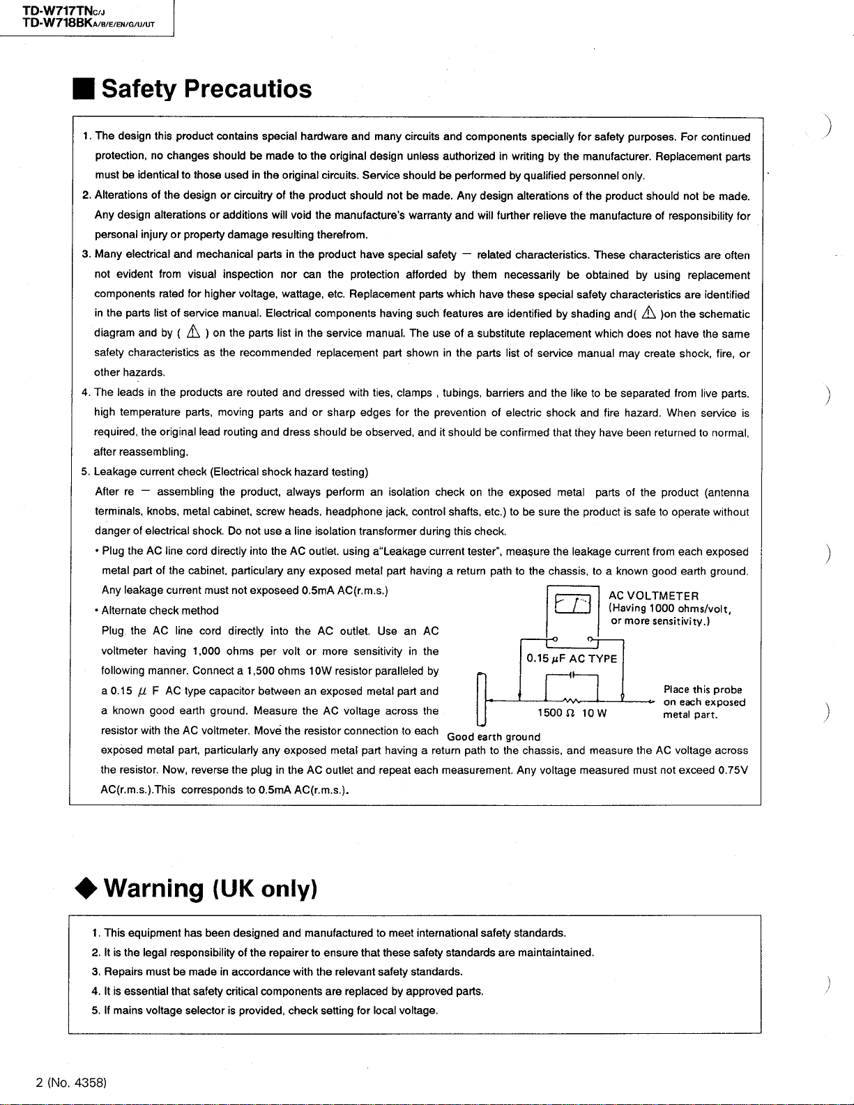
Leakage
.
After
terminals,knobs,metal
danger
Plug
•
metal
Any
•
Alternate
Plug
voltmeter
following
a
0.15
a
resistor
exposed
the
AC
this
,
no
changes
be
identical
alterations
design
or
injury
electrical
evident
parts
characteristicsasthe
hazards
leadsinthe
temperature
reassembling
re
theACline
leakage
from
rated
listofservice
by
and
.
,
original
the
current
—
assembling
of
electrical
part
of
current
and
the
check
the
AC
having
manner
AC
(
1
F
known
good
the
with
metal
resistor
.
Now
.
m
r
.s.).
(
This
Precautios
product
contains
shouldbemadetothe
to
those
design
or
property
mechanical
visual
for
higher
(
)
on
products
,
parts
moving
lead
.
check(Electrical
the
cabinet
shock.Do
directly
cord
cabinet
must
method
line
cord
,
1
000
Connect
.
type
capacitor
ground
earth
AC
voltmeter
,
part
particularly
,
reverse
corresponds
special
usedinthe
circuitry
or
additions
damage
inspection
voltage
manual.Electrical
the
recommended
are
routing
product
,
particulary
not
directly
ohms
a
the
of
will
resulting
parts
,
list
parts
routed
parts
and
shock
,
,
screw
use
not
into
the
exposeed
into
per
,
1
ohms
500
between
Measure
.
Move
.
any
plug
in
0.5
to
mA
original
the
in
nor
wattage
and
and
dress
always
heads
a
any
volt
the
exposed
the
hardware
product
void
the
therefrom
product
the
can
components
in
the
replacement
dressed
or
should
hazard
,
line
isolation
AC
outlet
exposed
0.5
mA
the
AC
or
10
an
the
resistor
AC
(
AC
r.m
and
many
original
design
.
circuits
Service
should
manufacture
.
have
the
protection
,
Replacement
etc
.
having
service
manual.The
part
with
ties
sharp
edges
be
observed,anditshould
)
testing
perform
headphone
more
W
exposed
AC
outlet
an
transformer
,
using
aTeakage
metal
AC
s
(
.
r.m
.
outlet.Use
sensitivity
resistor
paralleled
metal
voltage
connectiontoeach
metal
part
repeat
and
)
.s.
.
circuits
unless
should
be
not
'
s
warranty
special
afforded
such
showninthe
,
clamps
the
for
isolation
,
jack
control
having
part
)
an
in
part
across
having
each
and
authorized
be
.
made
safety
parts
which
features
useofa
,
tubings
prevention
check
shafts
during
current
a
AC
the
by
and
the
Good
a
return
measurement
components
performed
Any
design
and
will
—
related
them
by
have
are
substitute
parts
,
barriers
of
be
the
on
,
etc
this
check
tester
return
path
earth
path
to
specially
writing
in
by
qualified
alterations
further
relieve
characteristics
necessarily
these
special
identified
replacement
listofservice
and
electric
confirmed
exposed
)
be
sure
to
.
.
"
,
measure
the
to
0.15
1500
ground
the
chassis,and
Any
voltage
.
by
the
personnel
the
be
by
shading
the
like
shock
that
metal
the
the
leakage
chassis
m
pF
AC
ft
safety
for
manufacturer
product
of
the
manufacture
.
These
obtained
safety
characteristics
and
which
be
to
and
fire
have
parts
product
current
,
known
a
to
AC
(
Having
or
o
-
TYPE
10
W
measure
measured
may
separated
manual
they
purposes
only
.
Replacement
.
.
should
of
responsibility
characteristics
by
using
(
)
on
\
A
does
hazard
been
of
is
create
the
safe
have
not
from
When
.
returned
product
to
operate
each
from
good
VOLTMETER
1000
sensitivity
•
<
*
the
Place
on
metal
AC
not
ohms
voltage
exceed
more
must
For
continued
be
not
made
are
often
replacement
are
identified
the
schematic
the
same
,
shock
fire
live
parts
service
to
normal
antenna
(
without
exposed
earth
ground
/
volt
)
.
probe
this
exposed
each
part
.
across
0.75
parts
for
,
,
.
or
,
is
,
.
V
has
be
that
selector
(
been
made
safety
Warning
This
1
.
equipment
legal
It
.
is
the
2
3
.
Repairs
is
essential
It
4
.
If
.
mains
5
(
2
No
4358
.
)
responsibility
must
voltage
UK
designed
of
the
accordance
in
critical
provided
is
only
components
and
repairer
with
,
check
)
manufactured
that
ensure
to
the
relevant
replacedbyapproved
are
for
setting
to
these
safety
local
meet
standards
voltage
international
standards
safety
.
parts
.
safety
are
.
standards
.
maintaintained
.
Page 3

TD
TD
TNC
BKA
/
J
/B/
/G/
/
E
U/UT
EN
W
717
-
W
718
-
Important
(
Items
1
Securely
.
1
marking
Suffix
J
C
/E/EN/
/
A
B
U/UT
Power
2
.
3
.
4
.
cord:Make
inspect
exterior
J
C
EN
E
/
/
B
U
UT
/
A
Install
confirming
while
Wiring
terminal
)
a
When
terminalbythe
b
Arrange
)
terminal
end
)
c
The
air
and
the
in
Management
Demanding
power
the
fix
specified
in
Marking
521650 8
A
52
52
52
scratch
SPT
SPT
VDE O
<
BASEC
VDED
O
LTSA
cord
the
5
Z
5
G
5
cord
-
-
BS
-
the
end
wires
VTP
G
VTP
VTP
Power
G
the
installing
.
respective
of
the
space
distance
.
Special
8
o
OJ
s
u
.
r
903
C
Q
904
C
Q
Q
915
o
*
5
_
L
transformer
following
the
Description
approved
UL
-
F
021
-
F
021
-
F
021
sure
1
1
6500
>
F
2
bushing
marking.Bushing
the
from
the
of
anddamage
Attach m e n t
KP
KP
KP
power
soldering
before
binding
while
power
others
-
-
-
by
cord,winditaround
must
Points
Safety
7
LJ
r
937
R
J
while
.
following
.
W
10
W
10
C
419
-
KP
610
KP
-
KP
the
:
.
them
is
cords
be
Regading
Precautions
ll
Q
903
j
~
confirming
Model
No
.
TD-W
TD
-
TD-W
TD
-
markings
plu g
-
SU
or
-
1
SU
or
SE
or
3
A
-
H
8
560
specified
NIFCO
3.2
2271
nearby
solderedin
or
mm
W
W
P
1
P
-
1
more
its
717
717
718
718
and
tool
the
the
the
)
z
7
.
•
•
Other
.
8
Since
they
etc
-
C
All
A/B/E
specified
as
must
surface
Safety
on
the
mustnocontact
.
Following
up
condition
Partsinbox
,
R
R
901
902
,
R
1403
R
,
8444
R
Q
D
915
910
parts
903
well
,
914
C
C
904
fuses
/EN/
by
as
specified
be
well
R
Q
G
following
parts
for
[
ZD
,
921
R
,
2403
,
8491
,
8431
,
945
R
3300
must
UT
/U/
rating
the
themarking
by
as
by
parts
with
inflammables
are
purpose
the
be
must
,
,
923
R
,
1453
R
,
8494
Q
8481
25
pF
/
version
by
the
Q
,
V
securely
of
rating
the
marking
R
U
are
electolytic
.
controlled
|
|
937
R
2453
R
]
,
901
,
901
D
virsion
J
C
/
,
901
F
mA
800
or
of
©
©
/
hear
,
R
,
Q
D
of
R
903
902
in
UT
generation
capacitors
,
Make
.
,
938
8432
|
,
,
(
VENT
be
and
shown
U/UT
mA
315
or
^
Version
White
sure
of
,
940
R
R
,
8482
R
Q
Q
,
905
,
903
D
D
TYPE
connected
F
902
the
on
version
shownonthe
.
•
—
/B/
A
ones
,
wires
their
941
,
R
909
,
904
)
must
surface
,
/
E
,
R
8441
,
Q
D
F
903
G
lift
755
912
909
.
be
,
,
,
,
,
,
In
(
No
.
4358
)
3
Page 4
-
o
co
CJ
CO
HH
P
*
JVC
1
INSTRUCTIONS
7
TD
-
W
DOUBLE
SD
/
W
717
CASSETTE
/
W
DECK
718
A/B
/
TROUBLESHOOTING
What
appears
sure
first
.
..
.
1
Cassette
cannot
Is
the
cassette
•
When
2
PLAY
.
Is
the
tape
•
Tape
Are
•
Is
•
TAPE
Is
•
Sound
Is
•
Is
•
Is
•
Is
•
,
runs
butnosoundisheard
all
connections
MONITOR
the
position
VOLUME
the
quality
the
DOLBY
the
head
the
record
the
tape
3
.
J
.
4
be
to
be
button
too
poor
Is
section
/
playback
worn
trouble
loaded
positioned
Is
pressed
loosely
properly
switchofthe
?
controlofthe
.
NR
switch
dirty
?
out
is
not
.
correctly
,
wound
set
?
head
always
?
does
tape
?
.
and
securely
stereo
stereo
amplifier
right
the
to
magnetized
real
trouble
move
not
made
amplifier
position
?
3
.
Make
.
?
set
to
set
to
MIN
?
5
Recording
.
Are
•
Are
•
Is
the
•
6
.
Previous
Is
the
•
.
7
Since
tape
Is
the
the
•
Is
the
•
.
8
MUSIC
?
Are
•
or
do
9
BLANK
.
The
tion
does
Is
the
•
BLANK
ished
cannot
the
safety
all
connections
head
recording
erase
speed
pinch
tape
rewound
SCAN
operation
the
non
they
contain
SKIP
function
not
other
SKIP
.
be
tabs
section
Is
head
is
irregular
roller
recorded
-
indicator
deck
operating
operation
performed
of
cassette
properly
dirty
?
not
completely
?
dirty
,
or
capstan
tight
too
does
sections
high
level
is
properly
begins
.
tape
and
securely
erased
and
wow
dirty
?
?
function
not
too
noiseorhum
yet
the
lit
.
MUSIC
after
broken
flutter
properly
short
BLANK
SCAN
MUSIC
.
(
3
?
?
made
occur
sec
?
SKIP
SCAN
.
?
.
.
or
opera
has
less
c
a
o
MM
o
3
)
,
CO
-
fin
-
99
J>J
>
OO
J
^
00
H
o
>
>
m
m
z
o
H
/
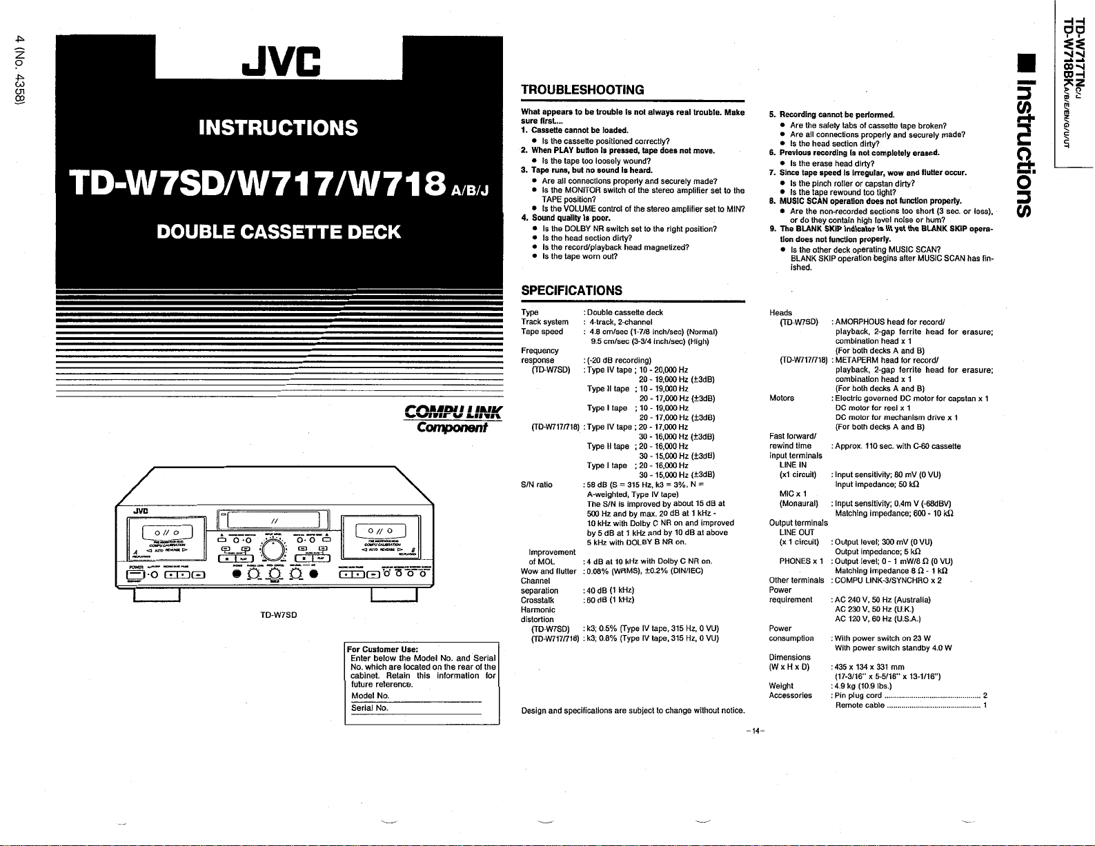
SPECIFICATIONS
E
POWER
I
JVC
^
3
o//o
COMPUCAUWMTiaN
AUTO
JCvtfctt
-
0
CUDGD
Type
Track
system
Tape
speed
Frequency
response
(
TD-W
\
r
r
-
/
/
O
ISf
an
•
0-0
«
»
f
I
C
.
a
.
HI
•
o
o
/
/
8
COVPV
CHJ
MTKN
AUTO
ACVlKtt
C
O
3
'
-
1
.
i
f
ronjiva
;
“
‘
b
S
tr
i
^
J
SD
TD-W
7
Use
Customer
For
Enter
No
cabinet
future
Model
Serial
which
.
below
are
Retain
.
reference
.
No
.
No
the
locatedonthe
%
Mt
*
6
.
n
wnr
V
*
Component
&
“
o
:
.
Model
this
and
No
rear
information
#
uivn
MMU
Serial
the
of
(
TD-W
/
N
S
ratio
Improvement
MOL
of
Wow
and
Channel
separation
Crosstalk
Harmonic
distortion
(
TD-W
(
TD-W
for
Design
SD
)
7
718
/
717
flutter
)
SD
7
718
/
717
specifications
and
)
)
Double
:
4
:
4.8
:
9.5
20
(
:
-
Type
:
Type
Type
Type
:
Type
Type
58
:
-
A
The
500
10
by
5
4
:
:
0.08
40
:
60
:
3
:
k
3
k
:
-
track
cm/sec
cm/sec
dB
IV
II
I
tape
IV
II
tape
I
(
dB
S
weighted
/
N
S
Hz
kHz
5
dB
with
kHz
dB
at
(
%
(
dB
1
dB
1
(
%
;
0.5
;
0.8
%
cassette
,
tape
tape
and
with
WRMS
are
deck
-
channel
2
-
7
(
8
inch
/
1
/
(
3-3
inch
4
recording
)
;
10
20
tape
-
20-19,000
;
10-19,000
17
20
-
;
10-19,000
20
17
-
;
17
tape
20
-
30
-
16.000
;
20-16,000
30
15,000
-
;
20-16,000
30
15,000
-
315
Hz
=
.
,
IV
Type
is
improved
.
by
max
Dolby
C
1
and
at
kHz
B
DOLBY
10
with
kHz
)
,
0.2
±
)
kHz
kHz
)
Type
(
tape
IV
Type
(
IV
tape
subjecttochange
,
,
,
3=3
k
tape
by
20
NR
NR
Dolby
%
000
000
,
000
000
by
sec
/
/
,
,
Normal
)
(
)
(
sec
High
Hz
(
3
±
Hz
Hz
(
3
±
Hz
Hz
(
Hz
3
±
Hz
(
3
Hz
±
Hz
3
(
Hz
±
Hz
(
3
±
Hz
,
N
%
=
)
about15dB
dB
at
1
kHz
and
on
dB
10
at
on
.
NR
C
(
/
IEC
DIN
,
315
0
Hz
315
0
,
Hz
without
)
)
)
dB
)
dB
dB
)
)
dB
dB
)
)
dB
at
-
improved
above
on
.
)
VU
)
VU
)
notice
.
-14-
Heads
-
(
W
TD
7
(
717
TD-W
Motors
forward
Fast
time
rewind
terminals
Input
LINE
IN
(
circuit
1
x
1
MIC
x
Monaural
(
terminals
Output
OUT
LINE
(
1
x
circuit
PHONES
terminals
Other
Power
requirement
Power
consumption
Dimensions
(
WxHxD
Weight
Accessories
SD
)
/
718
/
)
)
)
x
)
:
AMORPHOUS
playback
combination
For
(
:
)
METAPERM
playback
combination
For
(
Electric
:
DC
motor
DC
motor
(
For
Approx
:
Input
:
Input
Input
:
Matching
:
Output
Output
:
1
Output
Matching
:
COMPU
AC
240
:
230
AC
AC
120
With
:
With
435x134
:
3
(
17
-
kg
4.9
:
plug
Pin
:
Remote
,
2
-
both
decks
-
,
2
both
decks
governed
for
for
decks
both
.
110
sec
sensitivity
impedance
sensitivity
impedance
;
level
impedance
;
level
impedance
LINK
V
,
50
50
V
.
,
60
V
switch
power
switch
power
x
331
5-5
16
/
x
”
(
lbs
10.9
cord
cable
head
for
gap
ferrite
x
1
head
A
and
head
for
gap
ferrite
head
x
1
A
and
DC
reel
x
1
mechanism
and
A
with
.
;
80
mV
;
50
kfl
;
0.4
m
;
300
mV
;
5
-
0
mW
1
/
-
3
SYNCHRO
(
Australia
Hz
U
Hz
.K.
(
(
U
Hz
.S.
on
standby
mm
13
16
/
x
”
.
)
record
head
)
B
record
head
)
B
motor
drive
B
)
60
C
-
(
VU
0
-
(
68
V
600-10
VU
0
(
0
k
Q
8
/
-
O
8
)
)
.
)
A
W
23
16
/
1
-
.
/
/
for
cassette
)
dBV
kQ
)
0
VU
(
1
kfl
2
x
4.0
W
"
)
for
erasure
for
erasure
capstan
1
x
)
)
;
;
1
x
2
1
Page 5

2
o
CO
cn
CO
cn
A
CAUTION'TO
REFER
REDUCE
NOT
.
equipment
limits
the
of
can
used
cause
in
harmful
;
THE
EXPOSE
a
for
FCC
protection
installation
radiate
accordance
in
harmful
a
particular
WARNING
TO
DO
TURE
INFORMATION
This
the
15
reasonable
residential
and
and
may
However,there
occur
cause
CAUTION
BWX
OF
DO
REDUCE
DO
NOT
USER
NO
SERVICING
lightning
The
an
equilateral
presence
Ihe
to
product
the
within
magnitude
sufficient
shock
to
persons
The
exclamation
intendedtoalert
is
operating
important
instructionsInthe
appliance
.
RISK
OF
APPLIANCE
THIS
.
(
S
U
FOR
has
been
digital
Class
B
These
Rules
.
against
This
.
frequency
radio
interference
guarantee
no
is
installation
interference
ELECTRIC
SHOCK
HOT
OPEH
RISKOFELECTRIC
THE
REMOVE
COVER(OR
SERVICEABLE
TO
QUAUFED
with
flash
,
triangle
uninsulated
of
'
enclosure
s
to
.
point
the
and
literature
FIRE
)
.
A
.
tested
and
device
limits
harmful
equipment
energy
the
with
to
that
.
radio
to
If
SHOCK
)
BACK
INSIDE
PARTS
PERSONNEL
SERVICE
arrowhead
Is
Intendedtoalert
constituteariskofelectric
an
within
user
to
maintenance
accompanying
ELECTRIC
OR
TO
found
,
pursuant
designed
are
interference
instructions
radio
interference
this
television
or
"
,
symbol
within
the
"
dangerous
voltage
may
that
be
of
triangle
equilateral
the
presence
servicing
(
the
SHOCK
MOIS
OR
RAIN
comply
to
Part
to
to
provide
uses
,
generates
,
not
and
if
,
communications
will
does
equipment
reception
user
"
of
)
,
-
with
in
a
,
installed
not
.
.
-
IMPORTANT
Mains
DO
plug
homeorthe
then
leadorconsult
BE
approved
cover
nonetheless
If
the
possible
mains
DO
marked
coloured
The
in
As
markings
as
The
terminal
black
The
the
red
IF
Please
starting
rectly
ing
other
WARNING
Pre
re
right
or
tutes
can
which
the
user
one
or
Reorient
-
Increase
-
receiver
Connect
-
from
Consult
-
help
for
1
-
Supply
NOT
cut
fitted
obtain
SURE
.
and
fuse
shock
supply
make
NOT
with
greenorgreen
wiresInthe
accordance
s
.
these
colours
follows
:
wire
which
which
.
wire
which
terminal
.
DOUBT
IN
study
to
We
.
misuse
from
than
recorded
-
recorded
-
the
in
literary
infringement
an
determined
be
is
encouraged
of
more
relocate
or
the
.
equipment
the
which
to
that
dealer
the
.
(
In
the
(
AC
the
off
is
not
cable
appropriate
an
your
to
replace
,
type
as
the
dispose
hazard
.
any
the
letter
mains
with
identifying
is
Is
is
which
CONSULT
-
this
operate
take
no
instructed
(
the
In
tapes
without
sound
work
embodied
following
the
separation
the
or
Kingdom
United
V
230
50
plug
mains
suitable
for
is
shorttoreach
too
.
dealer
the
fuse
originally
fitted
plug
mains
of
the
plug
Inadvertent
by
connectiontothe
by
or
E
and
-
-
on
lead
following
the
may
not
correspond
the
terminals
blue
coloured
marked
with
coloured
brown
marked
Is
COMPETENT
A
instruction
,
unit
the
in
responsibility
by
this
unit
of
manual
this
in
Kingdom
United
,
records
consent
the
and
recording
that
in
copyright
of
by
turning
correct
to
try
to
measures
receiving
the
between
outlet
an
into
is
receiver
experienced
an
only
Hz
from
the
power
safety
only
and
is
cut
immediately
safety
the
yellow
this
code
in
must
the
must
the
with
manual
order
for
operating
.
)
discs
or
of
any
in
recording
.
equipment
the
the
:
antenna
on
connected
radio
)
)
equipment
this
points
a
power
approved
extension
an
with
replace
to
off
ensuretoremove
,
to
connectiontothe
terminal
symbol
earth
.
are
product
:
Blue
to
N
or
Neutral
(
)
L
Brown
to
(
)
Live
Red
or
the
with
your
plug
be
connectedtothe
letter
or
N
be
connected
or
letter
L
ELECTRICIAN
carefully
the
use
to
any
problems
equipment
this
should
the
owners
copyright
this
as
off
interference
.
equipment
the
different
circuit
a
.
technician
/
TV
If
.
your
in
point
identical
the
fuse
avoid
which
coloured
Black
coloured
proceed
coloured
coloured
before
cor
unit
result
not
copy
of
musical
consti
and
by
and
the
INTRODUCTION
you
Thank
for
carefully
reverse
loading
of
link
purchasing
and
operation
parts
control
,
a
is
or
book
performance
CONTENTS
Features
Auto
Cautions
Connections
Cassette
Names
Playback
Recording
Compu
Dubbing
Maintenance
Troubleshooting
Specifications
FEATURES
amorphous
Fine
.
1
.
2
Double
auto
deck
A
and
3
COMPU
CAL
.
characteristics
both
decks
on
logic
Fuli
*
Dolby
HX
Dolby
B
-
Built
in
•
filler
MPX
•
SD
7
W
Dynamics
(
DDRP
bility
The
DDRP
able
JVC
2
color
-
digit
linear
4
-
B
Synchro
.
Auto
tape
.
Multi
music
.
Blank
skip
.
control(deck
.
PITCH
Microphone
.
.
COMPU
only
718
noise
'
'
,
’
the
Dolby
of
mechanism
&
MPX
)
CD
FL
peak
start
select
UNK
difference
is
cosmetic
reduction
Corporation
Dolby
to
.
5
6
.
.
4
.
.
7
-
-
.
8
9
.
be
on
10
-
11
12
-
13
14
15
16
,
The
TD-W
Dolby
*
manufactured
Licensing
‘
*
marks
a
before
and
-
reverse
deck
PRO
C
linked
function
scan
function
mixing
under
doubie
JVC
operating
service
longer
their
functions
system
:
recording/playback
mechanism
B
which
function
brings
and
.
noise
player
tape
(
normal
3
-
Laboratories
out
headroom
extension
reduction
filter
the
Dolby
with
Recording
Detection
is
possible
.
indicator
level
respectively
counter
high
/
speed
-
-
mechanism(decksAand
mechanism
)
A
is
possible
compatible
between
one
.
and
HX
license
from
Pro
.
HX
D
symbol
-
Licensing
Read
.
product
to
life
automatically
maximum
system
for
Pro
originatedbyBang
EB
be
sure
from
heads
recording
for
NR
only
when
dubbing
)
either
models
headroom
Dolby
and
getting
of
the
unit
(
sets
tape
ON/OFF
Processor
used
deckAand
for
B
direction
TD-W
extension
Laboratories
"
PRO
HX
Corporation
this
instruction
optimum
.
TD
W
7
SD
-
/
playback
the
flat
performance
function
)
compati
a
with
)
and
717
&
Olufsen
"
are
trade
.
)
(
suit
deck
TD
2
2
2
4
4
.
5
6
7
11
12
13
14
14
in
-
-
-
.
-
2
—
COMPU
using
COMPU
panel
(
.
This
product
DETECTION
disc
pact
the
optimum
instructions
AUTO
The
auto
over
the
to
reaches
tape
Because
•
forward
the
directiontoobtain
During
•
the
forward
andtoavoid
,
rial
always
out
.
CAUTIONS
PreventionofElectric
.
1
)
Even
1
small
using
not
the
power
Do
not
)
2
)
3
When
the
plug
Consult
)
4
or
contact
5
Do
not
)
)
6
Do
not
)
Do
not
7
touch
)
8
AC
power
The
AC
connections
tion
for
9
not
Do
)
10
Unplug
)
.
ning
-
COMPULINK
Control
LINK
control
LINK
page
See
4
and
D
YNAM
RECORDING
be
can
RECORDING
cassette
player
+
recording
details
for
REVERSE
reverse
operation
reverse
of
during
its
end
of
cassette
direction
stable
,
auto
recording
the
reverse
to
accidental
start
recording
when
the
POWER
will
unit
the
cord
from
handle
the
not
the
,
your
nearest
failureisfound
bend
the
modify
the
remove
screws
inside
cord(For
cordofthis
power
prevent
to
connection
correct
any
insert
the
power
flow
for
power
from
power
cord
power
metallic
current
unplugging
anything
System
system
is
-
3
SVNCHRO
/
.
11
)
D
D-R-P
-
ICS
DETECTION
PROCESSOR
combinated
PROCESSOR
deck
automatically
level
.
OPERATION
this
unit
of
direction
forward
recordingorplayback
shell
construction
should
be
sound
reproduction
reverse
direction.For
erasure
of
the
with
,
Shocks
Fire
switch
To
save
.
extended
an
the
household
with
cord
the
wall
outlet
cord
.
dealer
when
the
with
,
sharply
or
cord
in
disassemble
to
.
the
unit
.S.A.
U
version
unit
has
electric
Fig
(
.
.
objects
cord
when
there
the
convenient
terminals
a
with
)
,
.
etc
turns
automatically
played
can
be
previously
side
Hazards
is
set
power
period
AC
wet
,
always
damage
cord
or
pull
any
manner
only
certain
shock
.
)
1
into
is
system
on
the
(
DYNAMICS
DDRP
system
)
to
enable
.
Refer
to
the
tape
transport
when
.
,
recorded
a
tape
back
in
the
.
activated
only
good
sound
recorded
the
of
A
tape
and
Damage
to
STANDBY
and
for
safety
,
disconnect
time
of
outlet
.
hands
.
grasp
,
disconnection
.
twist
it
.
the
unit
and
)
-
way
one
the
Refer
to
the
unit
.
a
possibilityoflight
rear
com
(
setting
these
the
same
from
quality
mate
facing
,
very
a
when
and
pull
do
not
direction
illustra
Fig
-
in
-
,
-
HH
DO
.
1
-
>
00
OH
>
in
m
m
z
O
I-M
i
-
o
^
si
5
Page 6

HH
)
O
:
z
o
4
^
CO
CJl
CO
water
)
If
11
outlet
Do
)
12
not
escape
)
13
Be
sure
going
period
.
2
Installation
Avoid
)
1
hum
vent
Move
the
unit
)
2
Avoid
peratures
near
humidity
3
this
)
If
warm
generated
ture
30
minutes
Cleaning
.
3
use
Never
the
damage
4
Cassette
.
Loose
1
)
anism.Remove
Fig
(
2
-
the
Turn
use
)
The
2
not
Is
occur
.
prevent
)
3
To
remove
adhesive
been
gets
Inside
the
the
install
not
unplug
when
.
the
being
to
as
the
etc
,
moved
,
may
it
inside
after
cabinet
unit
your
ventilation
the
the
the
unit
on
produced
place
a
possible
unit
40
or
)
.
suddenly
not
the
being
moved
.
finish
become
slack
by
i
A
and
consult
block
Do
.
to
or
out
of
time
placing
from
the
unit
as
far
installing
exceeding
heaters
,
dustorvibrations
Is
set
place
the
benzineorthinner
surface
tape
may
tape
)
If
to
tighten
pencil
minutes
120(120
of
C
-
recommended,since
recordings
the
broken
Tab
tape
"B"
a
tab
with
(s)
erase
to
off
.
\
7
Side
XXL
\
Adhesive
,
the
unplug
dealer
.
holesofthe
badly
unit
a
in
power
unit
or
not
in
°
C
less
function
unit.The
tangled
winding
the
from
screwdriver.Reseal
and
cord
is
not
in
adjacent
by
some
affected
a
from
TV
location
a
1040
(
) (
F
than
0
.
a
from
properly
unitwill
.
cabinet
for
the
in
the
tape
.
turn
characteristic
being
re
record
-
Side
from
use
to
by
set
subject
e
°
C
cold
cleaningasthey
tape
around
erased
A
"
/
V
\
"B"
Tab
llj
$
3
7
tape
cord
power
unit
so
that
ventilated
outlet
the
an
for
amplifier
an
amplifiers
of
types
amplifier
the
.
to
ambient
sunlight
direct
.g.
°
,
F
)
32
excessive
(
(
0
place
becauseofmois
function
tape
transport
a
with
pencil
)
thinner
or
deterioration
accidentally
the
the
after
”
"A"
from
heat
place
when
extended
to
,
pre
.
Keep
tem
°
to
)
C
properly
may
mech
.
Fig
tape
may
slots
with
tabs
have
Fig
the
can
.
.
)
4
Do
not
store
.
g
e
near
(
.
tures
humidity
or
5
Auto
.
tape
select
This
deck
has
guishes
between
After
cassette
.
equalization
-
.
-
,
a
-
-
.
2
,
3
Cassettes
•
Cassettes
•
Some
not
tapes
obtained
teristics
6
Operations
.
When
)
1
the
be
(
STANDBY
pressed
Many
)
2
a
of
ing
are
this
If
again
Metal
tape
(
chrome
02
Cr
Normal
earlier
be
provided
,
since
.
Also
do
the
POWER
deck
set
generated
.
operations
microcomputer
descriptions
the
incorrectly
done
happens
that
,
so
cassette
,
a
)
.
TV
orina
etc
.
mechanism(decks
Auto
an
different
type
the
are
set
to
with
the
detection
EQ
70
(
:
)
tape
without
the
EQ
:
(
tape
120
types
of
with
the
correct
equalization
do
not
not
match
detection
CrO
?
tape
holes
switchisturned
playbackorrecording
the
to
Before
.
,
confirm
)
this
of
Use
.
and
the
,
,
off
turn
unit
the
tapes
where
place
Tape
Select
types
of
tape
has
be
suitable
holes
s
)
«
/
EQ
s
70
(
:
<
/
detection
)
ts
/
metal
and
detection
use
ferrlchrome
this
unit
.
the
turning
that
the
unit
performed
are
the
unit
cautionsineach
may
unit
power
the
can
function
a
is
there
to
subject
and
A
B
mechanism
tape
of
from
detected
been
the
tape
for
:
)
holes
:
(
02
chrome
Cr
holes.Avoid
characteristics
tapes
tape
Metal
or
off(STANDBY
ON
mode
switch
POWER
button
(
)
stop
under
after
only
item
functioning
stop
,
and
once
correctly
magnetic
high
tempera
)
which
holesinthe
,
bias
.
tapes
)
using
cannot
whose
detection
,
noise
ON
has
the
carefully
.
If
operations
correctly
then
turn
.
distin
Type
Type
.
Type
charac
)
or
been
control
study
field
and
may
such
holes
with
may
it
CONNECTIONS
-
Do
•
completed
Insert
•
-
noise
When
•
white
reversed
IV
II
I
be
-
off
When
•
not
an
on
Connection
.
1
Note
When
your
-
.
on
CASSETTE
1
.
2
.
3
.
switch
the
not
.
the
plugs
the
pin
to
plug
connections
using
the
toastereo
.
If
the
-
or
the
plug
the
they
firmly
left
Compu
power
receiver
deck,be
.
connect
amplifier
/
off(STANDBY)function
:
installing
amplifier
LOADING
&
eject
)
the
a
cassette
the
sound
(
cassette
close
to
as
Press
Load
Press
click
until
on
power
poor
,
or
employed
cords
are
channel
terminal
.
Control
Link
cordtothe
Otherwise
.
cannot
amplifier
sure
stacked,noise(hum
are
CD
button
to
open
shown
.
holdertoclose
securely
the
holder
all
the
contact
,
.
System
SWITCHED
the
,
be
carried
to
install
Pin
player
the
cassette
Be
it
.
connections
will
result
always
This
helps
AC
automatic
out
a
distance
at
may
)
plug
-
sure
.
,
connect
version
OUTLET
.
occur
cords
holder
obtain
to
causing
avoid
to
,
3
power
from
.
(
provided
Deck
Remote
.
are
the
the
.
2
Remote
cable
connection
for
COMPU
By
connecting
a
cable
power
on
.
In
this
.
making
the
remote
.
making
be
connectedtothe
component
it
when
deck
can
which
LINK
Stereo
.
I
?
CD
with
remote
/
off(STANDBY
recording
provided
time
the
synchronized
cabletothe
synchronized
is
not
making
the
be
connected
have
the
COMPU
performance
amplifier
Remote
cable
player
)
Load
tape
and
a
-
exposed
•
matic
synchronized
formed
connected
When
•
do
of
nect
jacks
Notes
:
1
When
.
should
a
.
2
If
bypass
This
.
3
player
COMPU
TAPS
)
CX
;
:
s
<
provided
(
cable
,
COMPU
)
,
DDRP
recording
recordings
amplifier
JVC
remote
with
.
See
(
(
provided
the
cassette
LINK
LINK
automatic
recording
-
plug
pin
with
COMPU
.
COMPU
cable
an
/
1
LINK
-
page
with
edge
functions
source
can
)
cords
must
a
CD
3
LINK
-
onlyasingle
,
LINK
connections
amplifier
SYNCHRO
details
for
11
)
the
down
.
(
auto
selection
be
per
be
also
con
player
,
/
SYNCHRO
deck
component
.
and
a
jacks
)
.
CD
for
DO
si
00
-
CDH
o
>
5
?
^
m
m
z
-
o
c
,
5
-
-
,
-3-
-4-
Page 7

o
CJ
CJ
CO
1
NAMES
POWER
O
Cassette
©
Cassette
©
(
)
stop
PLAY
REC/REC
•
II
PAUSE
o
direction
(
*
-
eject
(
)
-
0
STANDBY
Power
0
wheninthe
Lights
COUNTER
0
Press
this
the
POWER
that
timeisstored
COMPU
©
Press
this
teristics
Indicators
0
DDRP
©
HX
©
Peak
©
These
being
tape
Note
dB
0
0
VU
CXJ
OF
PARTS
JVC
A
Q
|
0
(
switch
ON
holder(deck
operation
:
:
:
:
:
MUTE
:
)
:
button(deck
Indicator
RESET
button
to
switch
button
CAL
button
to
the
COMPU
with
indicator
indicator
PRO
level
indicator
indicators
recordedorthe
.
:
I
EC
:
Signal
:
DOLBY
:
AND
o
o
/
/
D
«
[
|
i m
i
-
/
STANDBY
)
)
A
buttons
(
deck
Presstowind
Press
left
to
.
operate
MUSIC
to
Presstowind
Press
.
MUSIC
to
stop
start
to
the
PLAY
to
an
appropriate
(
.
See
to
stop
to
Press
.
)
A
standby
deck
(
the
set
digital
set
to
STANDBY
memory
and
indicator(deck
automatically
CAL
light
according
level
STANDARD
)
level
at
STANDARD
NR
this
start
page
and
change
A
.
function
of
160
right
operate
Press
Press
Press
button
leave
tion
Press
recording
buttontorelease
travel
power
button
is
in
(
DIN
THEIR
0
6
0
0
o
•
©
A
)
the
quickly
tape
during
this
button
SCAN
.
quickly
the
tape
button
during
.
.
while
non
)
temporarily
pause
the
.
,
the
A
the
See
(
.
the
signal
/
m
LEVEL
.
direction
to
)
recording
levelofthe
playback
pressing
,
and
recorded
-
Press
mode
"
0.00
counter
page
recordedonthe
nWb
250
(
SCAN
the
tape
playback/recording
button
recording
.
10
tape
the
playback
the
mode
)
counter
set
to
the
LEVEL
nWb
FUNCTIONS
0
0
/
/
)
R
3
CH
PUT
o
this
o
)
d
©
to
to
to
-
if
at
©
©
-
©
0
©
©
©
©
5
-
-
O
from
playback
from
.
press
during
the
.
of
Even
.
"
value
charac
8
.
)
/
m
right
left
sec
PLAY
tape
signal
)
O
©
61
o
PUY
•
© ©
Digital
©
Normally
ing
the
be
skipped
Mechanism
©
REC
II
PLAY
<
,
S
4
DUBBING
©
CONT
®
Mechanism
©
©
<£>
CAL
COMPU
Refer
to
Q
COUNTER
eject
(
)
button(deck
—
Cassette
BLANK
SKIP
When
this
recorded
non
-
automatically
deck
resume
and
PHONES
Connects
PHONES
headphones
Controls
LEVEL
INPUT
page
See
cb
counter
operates
Music
Scan
displayed
is
mode
.
>
»
mode
button
.
RESET
button
holder(deck
button
is
button
section
playback
jack
headphones
LEVEL
control
control
.
9
0
o
/
/
c
a
as
digit
4
-
mode,the
.
indicators
:
lights
This
from
left
This
lights
:
right
from
when
Lights
:
and
record
ing
record
Lights
in
:
lights
This
:
Indicates
:
lights
:
">"
dubbing
"»"
lights
dubbing
Lights
:
when
play
uous
continuous
indicators(deck
Refer
to
:
:
Indicates
and
indicator(deck
(
deck
)
B
)
B
and
indicator
'
d
ON
turne
of
)
over
the
to
skips
.
an
(
with
.
volume
o
B
.
o
9 9
©
©
©
linear
tape
number
of
tunes
deck
(
)
A
winding
when
right
to
.
winding
when
left
to
.
is
the
unit
pause
modes;blinks
-
muting
.
pause
the
mode
wheninthe
the
direction
whenInthe
mode
.
wheninthe
.
mode
the
unit
isinthe
in
mode
or
recording
mode
)
B
.
®
mode
reverse
)
B
B
)
during
playback
15
secondsisdetected
beginning
of
impedance
of
counter
which
in
the
.
playback
of
tape
normal
high
the
.
.
if
,
a
the
next
to
fi
8
Dur
.
the
tape
tape
the
record
dur
.
travel
-
speed
speed
-
contin
alternate
blank
,
tune
kfi
1
will
the
)
Q
©
©
HXPRO
L
ODHP
H
+
-
88
88
©
control(deck
PITCH
0
the
tape
Varies
,
>
£
MIC
)
kO
to
NR
MPX
or
to
be
3
B
NORM
HIGH
to
B
OFF
Dolby
OFF
changes
cannot
it
.
counterclockwise
it
to
decrease
increase.The
to
it
.
speed
microphone
microphone
the
jack
a
microphone
jack
this
to
the
from
operation
.
©
button
NR
or
for
C
back
a
.
Each
time
and
the
Dolby
>
-
filter
turns
C
NR
when
MODE
the
single
play
.
checked
SYNCHRO
from
SPEED
SPEED
However
dubbing
Turning
speed
causes
standard
Mixing
©
-
Adjusts
MIX
©
Connects
10
Sounds
Cassette
©
Refer
DOLBY
©
Set
-
playing
system
changes
-
.
The
NR
Set
REVERSE
©
Select
-
continuous
mode
can
C
A
©
Presstodub
•
•
(
a
REG
4
uLm
»
PLAY
«
©
©
)
A
in
speed
change
while
(
page
See
level
.
microphone
buttons(deck
and
indicators
recording
that
tape
the
indicator
B
NR
ON/OFF
is
ON/OFF
the
Dolby
switch
or
side
mode
.
(
>
-
^
the
with
For
single
:
To
play
:
To
play
:
DUBBING
deck
Press
:
:
Press
o
Eife
»
>
©
A
deck
the
tape
toward
turning
center
)
7
.
control
level
input
an
with
(
are
using
was
recorded
button
lights
.
)
...
depending
(
TD-W
system
NR
record
full
Each
time
p
*
<
mechanism
-
side
record
or
sidesAand
buttons
deck
to
A
to
perform
perform
to
?
©
in
the
speed
"
SLOW
clockwise
click
.
impedance
monaural
B
)
Dolby
the
is
pressed
Dolby
(
SD
7
/
playback
the
-
>
^
mode
recording
both
.
B
normal
high
-
&
88
range
in
”
position
.
NR
using
B
NR
on
only
Is
not
button
)
The
...
sidesAand
continuously
B
speed
-
©
cr
88
©
about
of
the
high
causes
toward
of
system
the
the
Dolby
>
-
whether
)
.
used
mode
is
pressed
current
indicator
playback
or
speed
-
dubbing
>
±
-
speed
the
"
FAST
for
is
600
Dolby
NR
Dolby
.
or
,
.
dubbing
10
or
mode
C
mode
B
.
.
tape
£
2
.
%
”
the
to
for
NR
NR
B
the
the
.
.
.
.
-6-
PLAYBACK
Playback
Operate
©
Q
©
O
Q
G
•
Playback
Perform
Microphone
By
sound
Continuous
First
Load
the
•
•
Note
•
deck
of
the
orderofthe
in
Press
the
POWER
Load
prerecorded
a
the
sidetobe
Select
...
A
Forward
Side
B
.
.
Reverse
Side
.
DOLBY
the
Set
recorded
was
tape
REVERSE
the
Select
Press
the
PLAY
When
the
deck
and
matically
PLAY
play
end
switchestothe
mode
These
While
can
background
Use
button
of
steps
connecting
from
the
set
cassette
decktobe
this
time,the
At
When
.
of
side
At
.
operations
one
be
replaced
:
tapes
.
B
.
deck
©
mixing
a
deck
play
REVERSE
tapes
played
the
the
deck
music
recorded
microphone,microphone
B
A
numbers
to
switch
cassette
played
direction
direction
NR
switch
.
MODE
buttonofdeck
a
contains
the
A
played
is
tape
B
the
above
of
to
0
during
playback
or
deckBis
MODE
both
decks
in
first
for
indicator
CONT
the
deck
in
tape
(
the
reverse
in
forward
direction
time,the
same
continue
playing
is
back
Thisisconvenient
.
.
the
using
in
to
set
ON
side
with
back
.
(
PLAY
£
(
<
PLAY
^
same
to
the
.
to
A
the
,
tape
back
procedure
possible
switch
to
and
press
continuous
lights
which
direction
other
between
the
cassette
,
for
same
illustration
the
.
facing
A
)
>
)
setting
playback
start
deck
is
by
only
for
mixing
.
.
o
the
play
of
in
the
plays
first
,
)
it
and
enters
deck
starts
decksAand
-
long
time
modeindecks
NR
.
out
.
when
as
.
turned
on
pressing
deck
B
playback
with
button
PLAY
both
decks
multimode
reaches
automatically
standby
the
playback
B
.
the
other
in
playback
auto
.
A
the
the
.
dis
the
one
and
-
of
-
.
of
HH
DO
sJ
Nl
-
4
00
*
OH
o
>
<
CD
-
m
m
z
o
Page 8

CO
HH
D O
o
CO
CJ
CO
1
00
^
r a n
PITCH
1
is
It
about
for
possible
the
MULTI
The
•
quickly
before
The
•
recorded
The
•
Example
\
PL
<
/
Procedure
Press
1
.
When
.
2
1
want
displayed
Music
•
and
Relation
•
Notes
In
rectly
ing
Tapes
•
quiet
Tapes
•
BLANK
Press
•
lights
tion
deck
resumes
10
±
%
standard
MUSIC
multi
locate
or
multi
illustration
of
i
/
AY
>
\
i
on
•
I
I
<
*
L
MUSIC
the
more
press
to
Scan
,
B
but
:
:
:
following
the
.
This
the
to
with
parts
with
SKIP
the
)
before
)
over
of
automatically
deck
vary
to
the
playback
in
tape
SCAN
music
scan
beginning
the
the
after
scan
music
sections
between
shows
fast
forward
i
i
u
I
button
than
2
or
the
(
skip
tunes
the
counter
in
Operation
simultaneously
not
Multi
between
The
multi
sideofthe
(
than
more
,
)
side
the
.
reached
operates
It
andBsides
been
reached,the
side.When
or
from
B
recorded
from
side
,
tunes
in
one
ton
extra
cases
a
is
not
program
type
of
tunes
non
)
or
-
short
non
BLANK
playback
secondsisdetected
15
playback
)
A
the
speed
tape
mode
.
speed
mechanismofthis
of
current
tune
mechanism
tunes
the
forward
scan
.
during
playback
are
tunes
to
button
)
MM
.
The
number
.
can
be
.
Music
Scan
scan
music
only
tape
.
there
are
stops
tape
continuously
tape
the
of
tape
head
the
rotationIscounted
this
,
A
When
.
section
this
B
,
to
A
a
case
such
time
.
,
mechanism
the
malfunction
.
having
long
portions
recorded
-
recorded
button
SKIP
Whenablank
.
into
goes
beginning
the
from
in
deck
.
The
center
a
specific
.
)
functions
(
more
of
direction
.
skipped
be
the
numberoftimes
of
tunes
performed
and
mechanism
the
number
If
tunes
when
the
through
.
If
the
stops
rotates
to
recorded
a
tune
,
the
press
may
use
the
;
pianissimo
during
.
sections
to
turn
a
(
during
forward
fast
-
of
the
A
in
click
unit
allows
tune
(
up
by
detecting
than
4
.
nn
i
i
u
•
n
,
after
be
to
both
on
REVERSE
operates
setistoo
remaining
endofthe
one
cycle
number
the
endofthe
at
side
play
as
tune
is
recorded
(or)
M
<
not
operate
mechanism
passages(very
tunes
(
the
ON
it
recorded
non
-
playback
scan
next
the
range
position
you
to
99
tunes
sec
5
-
procedure
skipped
decks
MODE
on
on
tape
the
of
has
set
from
A
one
continues
as
accord
.
indicator
mode
tune
.
non
)
.
.
high
that
non
but
cor
sec
,
and
you
.
one
not
two
the
of
is
to
-
is
A
is
A
B
B
-
-
-
-
-
Notes
:
If
the
other
has
BLANK
operation
a
non
.
the
Operates
:
Operates
Operates
deck
stops
finished
on
may
recorded
-
Reset
BLANK
between
SKIP
is
the
not
PITCH
on
continuously
on
.
1
operation
deck
The
.
2
SKIP
Depending
3
.
operation
with
played
repeat
Relation
•
tions
^
RECORDING
:
in
sure
recorded
-
owner
,
musical
POWER
DOLBY
Deck
the
be
or
NR
the
order
noted
of
B
safety
tapes
copyright
cable
,
or
Example
Operate
Make
•
should
It
pre
the
of
broadcast
matic
O
o
o
CAL
COMPU
o
isinMusic
momentarily
.
indicator
canceled
PITCH
be
performed
portion
controltothe
SKIP
operation
REVERSE
sideofthe
one
both
sidesofthe
the
numbers
of
the
tab
of
that
it
may
,
records
in
programme
work
artistic
o
o
o
O
n
u
COUNTER
Scan
and
lights
momentarily
control
setting
in
of
over
.
MODE
tape
from
side
in
cassette
be
,
discs
or
the
soundorvideo
and
embodied
REC
REC
/
IIII
.
UU
RESET
mode,the
restarts
even
when
,
,
deck
15
center
and
BLANK
only
A
to
tape
.
the
illustration
has
not
unlawful
without
in
any
V
e
PAUSE
MUTE
©
BLANK
when
described
as
the
BLANK
A
evenifa
seconds
click
position
.
side
B
been
to
the
recording
literary
therein
PLAY
the
the
is
SKIP
.
.
broken
record
re
-
consent
.
SKIP
other
BLANK
in
SKIP
tape
being
and
Func
,
dra
Press
the
O
Load
a
0
the
Set
O
the
Set
Q
Select
G
the
Press
.
1
0
the
Press
Q
(
record
and
REC
Adjust
0
Press
to
O
the
Press
-
©
:
Notes
When
the
•
cannot
tape
tabs
are
When
the
•
sideBis
only
cally
.
Dynamics
(
DDRP
off
.
,
-
recording
DDRP
recording
the
recording
Since
different
control
LEVEL
Read
the
COMPU
This
•
automatically
mal
onds
IIorIV
Calibration
•
power
previous
new
Performing
•
data
COMPU
Insert
•
button
played
tape
indicator
Pressing
•
ations
To
recalibrate
•
wait
COMPU
Note
:
tape
the
If
error
will
check
to
utes
in
types
instruction
CALIBRATION
unit
tape
Calibration
.
)
.
is
tape
with
CAL
the
.
returns
.
for
the
the
POWER
cassette
DOLBY
REVERSE
side
the
COMPU
ll
PAUSE
-
pause
ll
indicators
the
recording
0.00
"
”
PLAY
safety
be
in
still
tape
is
level
level
of
tape
is
not
equipped
is
set
sensitivity
data
turned
calibration
is
recalled
COMPU
new
the
operation
tape
During
the
the
in
tape
to
lights
.
the
the
COMPU
button
CAL
near
is
be
generated
time
mode
play
switch
for
recording
switch
NR
MODE
switch
to
be
recorded
CAL
button
button
.
)
mode
light
level
.
button
to
tabs
removed
are
even
recorded
when
place
is
recordedinthe
recorded
and
Detection
performed
adjustment
adjustment
Type
(
I
required
of
your
book
(
COMPU
with
frequency
the
flat
each
for
dataisretained
set
with
COMPU
the
off
or
(
data
each
CAL
operations
.
data
to
be
recorded
operation
counter
its
starting
COMPU
CALIBRATION
(
)
button
stop
,
the
unit
press
indicator
CAL
again
.
,
its
end
it
during
remaining
)
before
to
set
to
.
as
required
as
.
,
if
required
and
•
.
.
page
(
See
start
recording
you
if
performing
reverse
then
Recording
suitable
with
is
performed
performed
is
)
,
II
or
IV
.
CD
a
COMPU
tape
for
CAL
cord
power
same
for
the
tapes
time
and
"
,
C
”
When
.
position
-
way
part
the
automatically
will
operation
on
the
starting
.
ON
.
.
desired
(
.
/
REC
REC
9
)
.
.
from
a
cassette
Make
try
.
full
recording
direction
the
tape
Processor
JVC
automatically
automatically
adjustment
,
the
carefully
player
CAL
)
FUNCTION
CAL
function
characteristics
approximately
in
each
tape
is
retained
is
unplugged
type
are
changed
again
replaces
the
press
"
CA
"
>
-
-
the
operation
and
the
,
now
is
will
interrupt
COMPU
go
.
to
out
Therefore
.
(
tape
more
the
operations
See
MUTE
sure
stops
CD
of
"
>
CAL
Then
below
button
tape
that
(
side
automati
recording
)
players
of
.
which
and
type
even
,
)
tape
.
existing
COMPU
CAL
"
finishes
COMPU
finished
the
button
,
press
stop
be
,
than
.
.
INPUT
30
(
Type
and
as
is
and
2
.
)
,
both
and
.
can
opti
sec
if
CAL
dis
,
CAL
.
oper
and
sure
min
the
the
the
the
the
the
COMPU
•
•
Care
cause
)
1
2
)
)
3
4)In
)
,
B
•
-
•
for
Notes
1
.
-
-
2
.
,
I
3
.
4
.
-
.
Errors
CAL
When
the
COMPU
CAL
COMPU
the
Press
should
be
of
errors
heads
Dirty
Scratches
on
When
the
tape
rare
cases
side
the
COMPU
When
an
error
,
interrupted
settings
were
If
are
values
retained
After
confirming
indication
if
rience
errors
values
preset
obtained
values
)
time
one
.
*
Preset
value
:
Since
COMPU
recorded
previously
new
Using
recommended
variance
Some
type
of
tape
when
precise
lor
operations
To
delete
contents
the
press
•
buttons.This
currently
insertedinthe
types
is
not
.
error
(
)
stop
button
taken
.
the
tape
ends
,
tapes
CAL
occurs
calibration
previously
items
there
are
be
can
or
©
by
a
standard
:
of
tape
preset
COMPU
CAL
and
tapes
for
optimal
in
characteristics
made
settings
each
REC/REC
deletes
deleted
CAL
the
for
Clean
-
surface
-
part
-
-
may
setting
or
data
.
)
1
no
recorded
previous
opening
which
,
value
CAL
operations
contents
cleaning
by
the
are
recording
set
with
MUTE
the
unit
.
indicator
to
stop
following
the
Replace
way
through
Change
have
characteristics
range
COMPU
when
cannot
performed
3
above
to
)
problems
on
setting
and
closing
corresponding
value
allows
condition
indicator
record
will
COMPU
same
desired
is
COMPU
and
calibration
.
Calibration
,
flashes
this
the
error
indication
as
items
heads
.
undamaged
with
an
the
operations
tape
the
position
.
CAL
operations
be
stored
in
,
the
previous
and
stopping
,
even
tapes
using
either
values
(
.
the
cassette
normal
recording
is
effect
in
.
)
is
unlit
a
test
be
erased
.
the
heads
beforehand
operations
CAL
even
exists
manufacturer
,
performing
recommended
,
CAL
simultaneously
deck
COUNTER
B
lor
the
data
data
indicates
they
which
the
which
©
These
to
each
tone
with
Therefore
.
COMPU
.
type
other
for
.
are
tape
.
fail
memory
setting
error
the
expe
the
unit
are
holder
.
when
tapes
on
.
the
same
RESET
of
out
type
(
The
CAL
tape
tape
are
are
the
the
the
a
.
-
.
-
'
s
,
,
-
an
-
(
control
z
o
>
*
t
D
m
z
D
H
8
-
7
-
-
-
Page 9

z
o
4
CO
CJ
00
CO
:
^
1
A
AND
V
CONTINUOUS
DECK
ALTERNATE
DECK
o
CcSlr
O
0
©
©
Q
0
o
©
Q
Q
When
•
other
stops
When
•
recording
done
recording
pause
mode
To
Press
3
Y
DOU
NR
MUTE
REC
REC
/
MUTE
REC/REC
Load
the
tapes
facing
(
Be
out
the
the
deck
level
deck
REC/REC
•
this
or
that
.
,
flashing
beginning
for
.
the
.
the
DOLBY
REVERSE
to
A
.
B
,
time
indicator
will
PLAY
the
recording
the
CONT
B
side
automatically
about
from
)
mode
record
the
(
stop
direction
(
the
to
MUTE
the
be
.
of
of
3
deck
first
)
A
Press
directionsofdecks
Set
set
Set
ing
Set
In
^
tape
Press
starts
the
cancel
RECORDING
B
WITH
AUTOMATIC
©
o
PAUSE
©
be
recordedindecksAand
to
wind
to
)
buttonstoselect
and
A
B
switch
switch
pause
-
record
)
button
.
and
,
.
of
in
goes
finishes
A
.
If
,
the
A
with
,
set
B
and
set
standby
the
on
past
.
required
as
mode
standby
-
CONT
showing
deck
one
off
both
continuous
two
deck
deck
mode
deck
sure
NR
MODE
record
the
REC
flashes
recorded
button
finishes
indicator
deck
side
hours
-
button
the
to
*
<
mode
indicators
the
;
A
deck
and
recording
decks
90
C
-
to
B
A
.
during
BETWEEN
SELECTION
5
E
REYER
MODE
leader
tape
the
.
.
:
>
adjust
and
,
press
(
light
directionofthe
continuous
continuesinthe
and
or
the
4
,
deck
recording
start
recording
When
.
tapes
record
the
the
record
to
record
B
tapes
the
(
standby
-
with
or
sides
.
)
transport
record
only
the
,
and
next
recording
Indicator
starts
B
from
will
starting
record
standby
-
-
the
be
-
.
-
MICROPHONE
By
connecting
recording
Adjust
mode
When
•
control
phone
RECORDING
Adjust
Indication.For
cator
Type
With
(
TD-W
-
i
30
L
.
na ao oo ua aa ao nr ao aa cD DC
R
«
=,=«=
(
TD-W
30
-
I
oaa aao auj aao aca ci coc DOC oac jat n
^
R
Becauseofmetal
occasionally
the
TD-W
Type
With
L
Qta
R
IsOKthat
It
When
•
the
in
When
•
tion
be
"
If
•
high
breaking
low
best
is
It
source
levelofthe
The
best
of
tape
records
9
-
Is
microphone
the
and
observing
the
is
,
and
recording
the
IV
7
)
SD
20
,
718
/
717
20
717
(
I
eso
rao
the
tape
the
level,the
distorted
lights
4
”
+
,
the
and
the
to
be
to
tape
level
so
it
,
etc
.
MIXING
a
possible
record
set
to
can
it
LEVEL
metal
(
15
12
)
15
12
"
,
4
"
+
718
/
.
normal
c
3
1
=
"
0
”
+
recording
will
recording
recording
.
recorded
If
up
.
recording
adjust
recorded
to
varies
Is
better
microphone
by
input
peak
the
pause
-
,
sounds
MIN
be
used
ADJUSTMENT
level
example
)
tape
8
10
8
10
'
s
higher
tape
lights
on
Type
or
)
n
=
occasionally
lights
level
conspicuous
be
level
often
too
sound
"
"
O
only
may
so
that
reaches
be
used
depending
make
to
following
while
DURING
RECORDING
,
microphone
the
by
level
setting
level
indicators
mode
is
set
are
output
as
a
public
observing
:
ovu
6
2
ovu
6
2
an ao uao a
saturation
the
W
TD
-
(
II
chrome
.
is
low
too
.
high
is
too
will
contain
the
because
distorted
be
may
infrequently
lights
contain
the
maximum
very
the
.
the
on
recording
a
test
recording
and
only
address
0
m
0
00
aa r
,
SD
7
)
tape
the
,
exceeding
,
cracking
recording
tape
limit
type
the
.
the
the
2
2
level
and
2
hiss
,
hiss
sound
of
,
mixing
from
peak
,
“
noise
noise
and
the
.
of
music
using
record
INPUT
system
4
4
It
+
4
the
during
procedure
-
pause
LEVEL
the
micro
.
level
indi
6
SdB
-t-
6+8
dB
IsOKthat
"
lights
2
dB
6
8
Inherent
the
satura
and
level
is
seem
to
level
is
levelofthe
saturation
and
type
music
FM
will
too
too
on
be
.
-
-
-
,
AUTOMATIC
This
an
.
A
.
B
C
.
•
ERASING
When
is
automatically
on
To
Follow
LEVEL
LINEAR
When
During
linear
timeinminutes
There
back
-
C
80
ent
a
different
DOLBY
Dolby
To
System
recorded
to
mode
Note
The
switch
RECORD
is
usedtoeliminate
facility
non
leave
When
the
.
the
press
The
REC
.
made
is
seconds
unit
enters
.
Press
the
non
leave
the
.
Keep
ouslyaslong
section
.
above
the
mode
.
Press
the
.
non
leave
the
undesired
the
•
button
again
-
pause
level
peak
exact
the
recording
.
tape
a
tape
the
section
control
TAPE
the
power
playback
tape
tape
counter
a
is
one
time
and
,
and
other
may
time
thickness
and
NR
System
NR
the
when
with
according
or
C
.
:
sound
quality
are
different
non
recorded
-
recorded
-
undesired
REC/REC
•
indicator
during
record
,
later
the
the
record
PLAY
button
recorded
-
REC/REC
•
as
By
releasing
operation
button
PLAY
recorded
-
section
/
REC
REC
the
before
,
or
press
mode
.
indicator
to
the
input
on
the
point
on
a
prerecorded
erased
and
without
“
RECORDING
to
.
MIN
COUNTER
is
connected
,
the
which
and
seconds
-
error
minute
playback
the
,
this
tapes
also
appear
.
DOLBYHXPRO
hiss
inherent
making
recordings
Dolby
NR
the
the
to
change
will
recording
in
you
appropriate
To
matically
1
2
3
To
1
2
To
When
After
PLAY
recording
record
The
according
speakersorheadphones
at
the
erase
reduce
B
MUTING
undesired
.
section
sections
of
comes
section
MUTE
button
and
flashes
muting
automatically
tape
-
mode
pause
to
start
of
sections
MUTE
want
to
the
finger
,
unit
the
to
start
sectionofless
comes
MUTE
button
unit
enters
the
PAUSE
ll
lights
even
which
level
that
so
recording
.
tape
tape
the
only
making
a
new
but
’
'
OPERATION
“
,
0.00
digital
counter
the
displays
-
46
for
C
differential
displayed
time
differential
of
for
tapes
recording
in
tape
When
.
,
System
system
the
if
positions
and
sections
about
seconds
4
5
-
during
and
release
recorded
a
non
-
operation
stops
.
recording
again
than
more
4
button
pressed
make
a
non
the
from
the
record
enters
recording
again
than
seconds
4
-
during
recording
is
pressed
the
mode
pause
button
during
record
be
can
heard
can
,
the
previous
program
new
recording
,
in
step
set
©
in
appears
”
operates
approximate
-
,
,
and
60
C
L
between
the
.
With
is
greater
even
length
the
same
,
use
listening
the
DOLBY
set
selectedinthe
the
of
playback
.
and
recording
About
.
,
seconds
5
-
-
recorded
button
,
press
to
enter
from
resumed
be
recording
is
recorded
.
.
.
the
the
as
playback
-
90
C
actual
30
C
-
.
the
Dolby
to
NR
recording
DOLBY
leave
auto
it
.
section
and
.
continu
after
pause
-
.
..
..
start
to
muting
INPUT
display
a
digit
4
-
tapes
play
,
C
differ
A
but
a
tape
switch
4
the
the
the
the
46
-
with
NR
NR
PRO
HX
Dolby
When
nents
function
changes
This
-
low
-
the
of
,
Dolby
current
-
5
are
signal
This
reducing
tion
.
-
The
•
same
not
This
•
ever
a
source
is
recorded,these
as
bias
.
will
result
frequency
high
frequency
-
PRO
HX
so
that
fluctuations
.
greatly
improves
the
dynamic
even
Dolby
have
system
Dolby
,
headroom
in
signal
the
low
when
HX
which
contains
high
and
therefore
phenomena
subsequent
and
saturation
headroom
effective
the
high
in
the
high
frequency
-
sound
recorded
tape
the
PRO
HX
automatically
is
PRO
not
extension
many
-
frequency
,
such
level
extension
bias
frequency
-
-
frequency
signal
played
is
.
works
noise
a
the
as
distortion
.
system
is
constant
components
level
with
back
when
reduction
-
high
frequency
signals
effective
changes
saturation
variations
system
this
in
in
have
bias
in
and
controls
even
deck
a
recording
system
compo
the
current
the
level
reduction
the
when
the
of
level
and
sounds
that
.
same
bias
there
input
while
distor
does
;
how
-
of
-
the
-
.
.
-
,
-
HH
OD
1
1
1
>
^
N
!
00
-
03
-10-
H
o
>
£
CD
m
m
z
D
N
Page 10
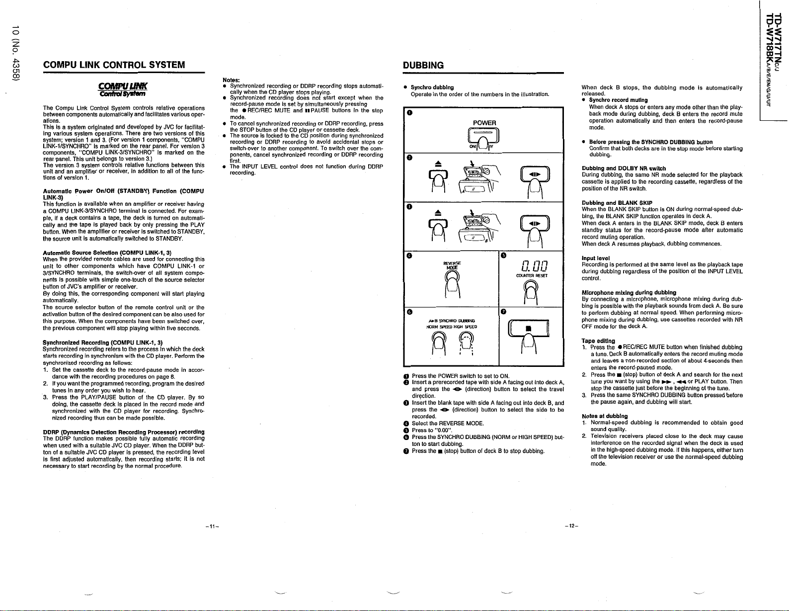
HH
DO
o
:
z
o
4
*
^
CO
CJ
CO
1
COMPU
The
Compu
components
between
ations
.
system
This
is
a
various
ing
system
LINK
components
rear
The
unit
tionsofversion
Automatic
LINK
This
a
ple
cally
button
the
Automatic
When
unit
3
nents
button
By
automatically
The
activation
this
the
Synchronized
Synchronized
starts
synchronized
1
2
3
DDRP
The
when
ton
is
necessary
;
version1and
/
1
SYNCHRO
-
panel
version
an
and
)
3
-
function
COMPU
,
a
deck
if
and
When
.
source
the
other
to
/
SYNCHRO
is
possible
of
JVC
doing
source
purpose
previous
recording
the
Set
.
dance
you
want
.
If
tunes
.
Press
doing
,
synchronized
nized
Dynamics
(
DDRP
used
a
suitable
of
adjusted
first
system
,
.
This
amplifier
Power
LINK
the
unit
Source
provided
this,the
buttonofthe
.
cassette
with
any
in
the
the
recording
function
with
to
LINK
CONTROL
COMPULINK
ControlSysfm
Link
Control
automatically
originated
operations
3
’
’
is
marked
“
COMPU
belongs
unit
system
3
controls
or
.
1
On/OH
is
available
3
SYNCHRO
/
-
a
contains
Is
played
tape
amplifier
the
automatically
is
Selection
remote
components
terminals,the
with
simple
s
amplifier
’
corresponding
.
selector
buttonofthe
desired
When
the
component
Recording
recording
in
synchronism
recording
deck
the
recording
the
programmed
order
you
/
PAUSE
PLAY
deck
cassette
the
with
thus
Detection
makes
suitable
a
JVC
CD
automatically
recording
start
System
and
developed
There
.
For
version
(
.
on
-
3
SYNCHRO
/
LINK
version
to
relative
,
receiver
(
STANDBY
an
when
terminal
,
tape
the
back
or
receiver
switched
(
COMPU
cables
which
switch
one
receiver
or
component
components
will
stop
(
COMPU
refers
to
with
as
follows
to
the
record
procedures
recording
wishtohear
buttonofthe
is
placed
player
CD
can
be
made
Recording
possible
JVC
CD
is
player
,
then
by
the
SYSTEM
controls
and
facilitates
are
two
1
components
rear
the
panel
"
)
.
3
functions
additiontoall
in
)
Function
amplifier
is
connected-For
deckisturned
by
only
switched
is
to
LINK
used
are
have
COMPU
of
-
over
the
-
touch
of
.
component
remote
can
have
been
within
playing
,
1
LINK
-
the
process
the
CD
:
-
pause
on
,
program
.
the
in
recording
for
possible
Processor
fully
automatic
When
player
.
,
pressed
recording
procedure
normal
relative
various
by
JVC
versions
For
.
is
marked
between
of
or
receiver
on
pressing
to
STANDBY
-
,
)
1
3
connecting
for
all
system
source
start
will
control
be
also
switched
five
)
3
which
In
Perform
.
player
mode
8
page
.
player
CD
record
.
)
the
recording
the
starts
operations
oper
for
facilitat
this
of
,
“
COMPU
version
on
the
this
the
func
(
COMPU
having
exam
automati
the
PLAY
STANDBY
.
this
-
1
LINK
compo
selector
playing
unitorthe
used
over
seconds
the
deck
the
accor
in
the
desired
By
.
mode
and
Synchro
.
recording
recording
DDRP
but
level
;
is
not
it
.
DUBBING
Notes
:
Synchronized
•
cally
when
the
Synchronized
•
record
pause
-
the
#
mode
To
•
the
The
•
recording
switch
ponents
first
The
•
recording
.
cancel
STOP
source
-
.
INPUT
REC/REC
synchronized
buttonofthe
Is
or
over
to
,
cancel
LEVEL
.
-
-
3
-
-
-
,
or
-
for
,
.
-
so
-
-
recording
player
CD
recording
mode
is
set
MUTE
lockedtothe
recording
DDRP
another
synchronized
control
or
DDRP
stops
does
by
simultaneously
and
PAUSE
ll
recording
CD
player
CD
position
to
component
recording
does
recording
playing
not
or
or
avoid
To
.
not
.
start
buttons
DDRP
cassette
during
accidental
switch
or
function
stops
except
pressing
recording
deck
synchronized
over
DDRP
during
automati
when
the
In
.
stops
the
recording
stop
,
press
com
DDRP
the
-
or
-
Synchro
•
Operate
o
o
o
Press
O
Insert
O
and
direction
Insert
Q
press
recorded
Select
O
Press
Q
Press
O
tontostart
Press
Q
dubbing
order
the
in
REVERSE
Moce
,
A
a
SYNCHRO
*
HIGH
SPEED
NORM
POWER
the
a
prerecorded
o
the
press
-
.
tape
the
blank
the
direction)buttontoselect
(
«
-
.
the
REVERSE
"
’
0.00
to
.
’
the
SYNCHRO
dubbing
(
stop
the
of
the
numbers
POWER
5
DUE
8
M
SPEED
switch
to
tape
with
direction)button
(
side
with
MODE
.
DUBBING
.
)
buttonofdeck
set
to
side
facing
A
(
NORM
deck
When
.
and
but
be
,
A
-
released
Synchro
•
deck
When
back
mode
operation
mode
.
Before
•
Confirm
dubbing
and
Dubbing
During
dubbing
is
cassette
of
position
Dubbing
and
When
the
bing
,
BLANK
the
When
deck
standby
status
record
muting
When
deck
Input
level
Recording
during
dubbing
.
control
Microphone
By
connecting
bing
possible
is
to
perform
mixing
phone
mode
OFF
editing
Tape
.
1
Press
the
.
a
tune
and
leaves
enters
2
.
Press
the
tune
you
stop
the
.
3
Press
the
the
pause
dubbing
Notes
at
Normal
.
1
sound
2
.
Television
interference
the
high
in
off
the
mode
.
the
in
o
COUNTER
ON
.
facing
A
to
out
or
B
to
stop
illustration
n
n
u.uu
RESET
into
out
select
into
deck
the
side
HIGH
SPEED
dubbing
the
n
deck
.
.
travel
B
,
to
)
,
the
B
stops
record
muting
A
or
enters
stops
during
dubbing
automatically
pressing
that
.
applied
the
BLANK
A
A
is
dubbing
for
Deck
the
-
speed
quality
television
SYNCHRO
the
both
decks
DOLBY
NR
,
the
same
the
to
switch
NR
.
BLANK
SKIP
SKIP
button
SKIP
function
the
enters
in
the
record
for
.
operation
resumes
playback,dubbing
performed
at
regardless
mixing
during
a
microphone,microphone
the
playback
with
normal
at
during
dubbing
A
.
deck
the
/
REC
REC
•
automatically
B
-
recorded
a
non
-
record
paused
(
)
stop
button
using
want
by
before
just
cassette
same
SYNCHRO
again
dubbing
,
and
dubbing
.
placed
receivers
on
the
recorded
dubbing
speed
-
receiver
dubbing
any
,
deck
and
then
in
are
switch
mode
NR
recording
is
ON
operates
BLANK
pause
-
the
same
of
the
dubbing
speed
,
use
MUTE
button
enters
section
mode
of
deckAand
the
the
DUBBING
is
recommended
close
signal
mode
or
use
mode
mode
B
enters
enters
DUBBING
the
stop
selected
cassette
during
in
SKIP
mode
level
position
sounds
.
When
cassettes
when
the
of
.
,
«
beginning
start
will
to
when
this
.
If
the
normal
is
automatically
other
than
the
the
record
button
mode
before
for
regardless
,
normal
deck
A
mode,deck
after
commences
as
playback
the
of
the
INPUT
mixing
from
deck
performing
recorded
finished
record
muting
-
about
seconds
4
search
or
PLAY
of
the
button
pressed
.
to
the
deck
the
deckisused
happens
speed
-
play
the
record
mute
pause
-
starting
the
playback
the
of
speed
dub
-
.
enters
B
automatic
.
tape
LEVEL
dub
during
sure
.
A
Be
micro
NR
with
dubbing
mode
then
the
for
next
button.Then
tune
.
before
obtain
good
may
cause
,
either
turn
dubbing
-
-
-
-
|
V
CO
COH
>
$
5
2
D
H
i
|
s
*
J
^
o
^
-11-
-12-
Page 11
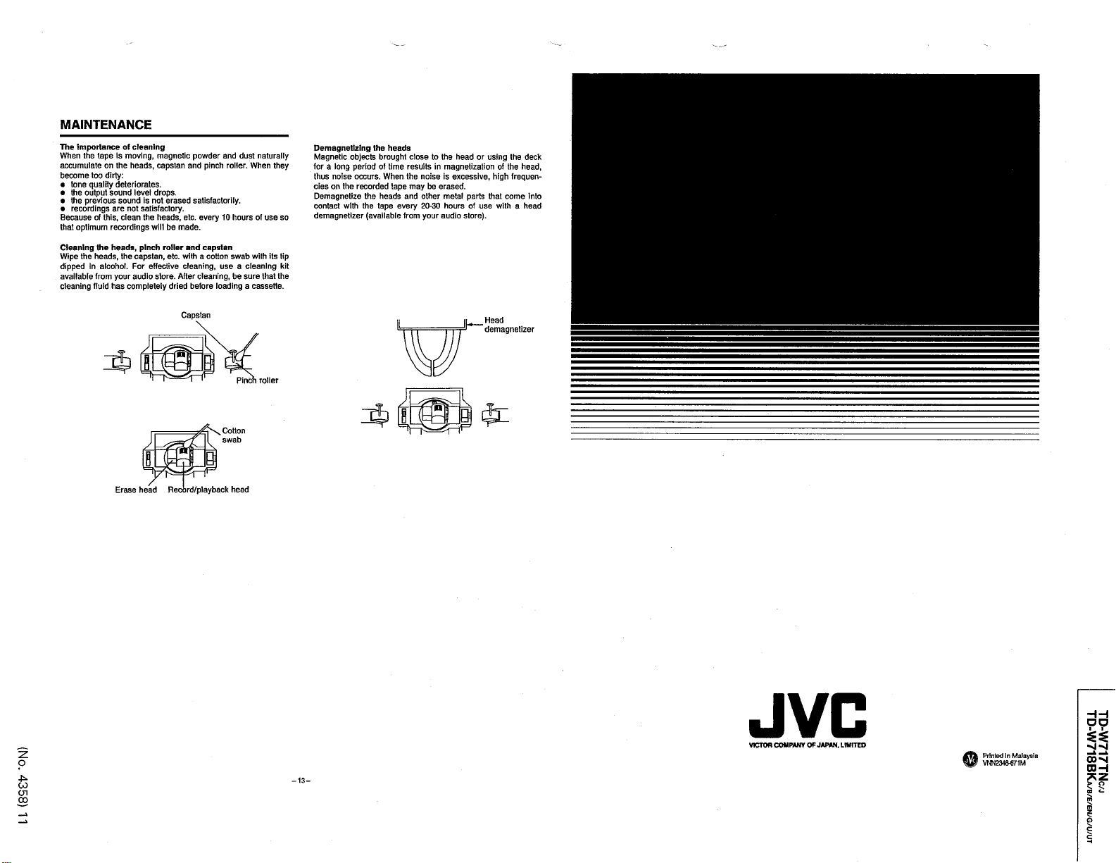
MAINTENANCE
The
importance
When
accumulateonthe
become
tone
•
the
•
the
•
recordings
•
Becauseofthis,clean
optimum
that
Cleaning
Wipe
dipped
available
cleaning
the
tape
too
quality
output
previous
the
the
heads,the
In
from
fluid
of
cleaning
is
moving,magnetic
heads
dirty
:
deteriorates
sound
sound
are
not
recordings
heads
capstan
alcohol.For
your
audio
completely
has
level
is
satisfactory
the
,
pinch
,
capstan
.
drops
erased
not
heads
be
will
roller
,
etc
effective
store
dried
.
.
.
.
,
made
After
etc
with
cleaning
powder
and
pinch
satisfactorily
every
.
.
and
capstan
a
cotton
,
cleaning
before
and
dust
roller.When
.
10
hours
swab
a
use
,
be
loading
naturally
of
with
cleaning
sure
that
a
cassette
use
the
objects
period
occurs
recorded
the
the
(
heads
brought
time
of
When
.
heads
tape
available
close
results
the
noiseisexcessive
may
tape
and
other
20
every
from
the
to
magnetization
in
be
erased
metal
hours
30
-
audio
your
head
.
store
parts
of
using
or
use
)
deck
the
,
the
head
of
high
,
frequen
-
that
into
come
with
a
head
.
Demagnetizing
Magnetic
they
so
tip
its
kit
the
.
long
a
for
thus
noise
the
cies
on
Demagnetize
with
contact
demagnetizer
o
CO
CO
2
4
CJI
Capstan
Pincn
roller
Head
demagnetizer
a
Cotton
swab
Record
I
playback
/
head
H H
DO
JVC
COMPANY
VICTOR
13
-
-
OF
JAPAN
LIMITED
.
Printed
VNN
2348
Malaysia
In
-
671
M
i
Nj
00
O H
»
J
*
§
m
m
z
a
s
s
H
si
-
Nl
-
2
O
"
1
Erase
head
^
Page 12

TD
TD
/
TNC
717
W
-
.
718
W
-
J
/
E
/
/B/
KA
B
UT
G
/U/
EN
Q
A
Power
]
Location
Top
view
A
stopper
Cord
cord
A
Power
Main
of
transformer
Parts
Power
supply
transistor
Main
board
asas
Model
i
y
’
-
:
TD
718
W
/
Mechanism
Top
view
Eject
B
/
)
Pinch
safety
(
Deck
Deck
Mechanism
Supply
roller
reel
Fig
ass
.
A
Reel
disk
'
y
1
-
motor
)
(
L
R/P
2
ass
Head
y
’
ass
Take
Pinch
'
y
-
up
roller
reel
ass
Mechanism
board
.
Fig
1-1
disk
'
)
(
y
R
ass
Bottom
+
control
y
’
Cam
©
is
a
view
motor
Deck
B
y
Mechanism
motor
Reel
motor
Reel
4
,
VW
-
1
FUHUKAWA
OS
/
-
I
V
ass
board
K
’
ass
'
y
m
.
FM
i
«
—
25
bracket
1
.
Fig
•
~
Capstan
3
-
II
•
<
:
*
*
motor
m
12
(
No
4358
.
)
Page 13
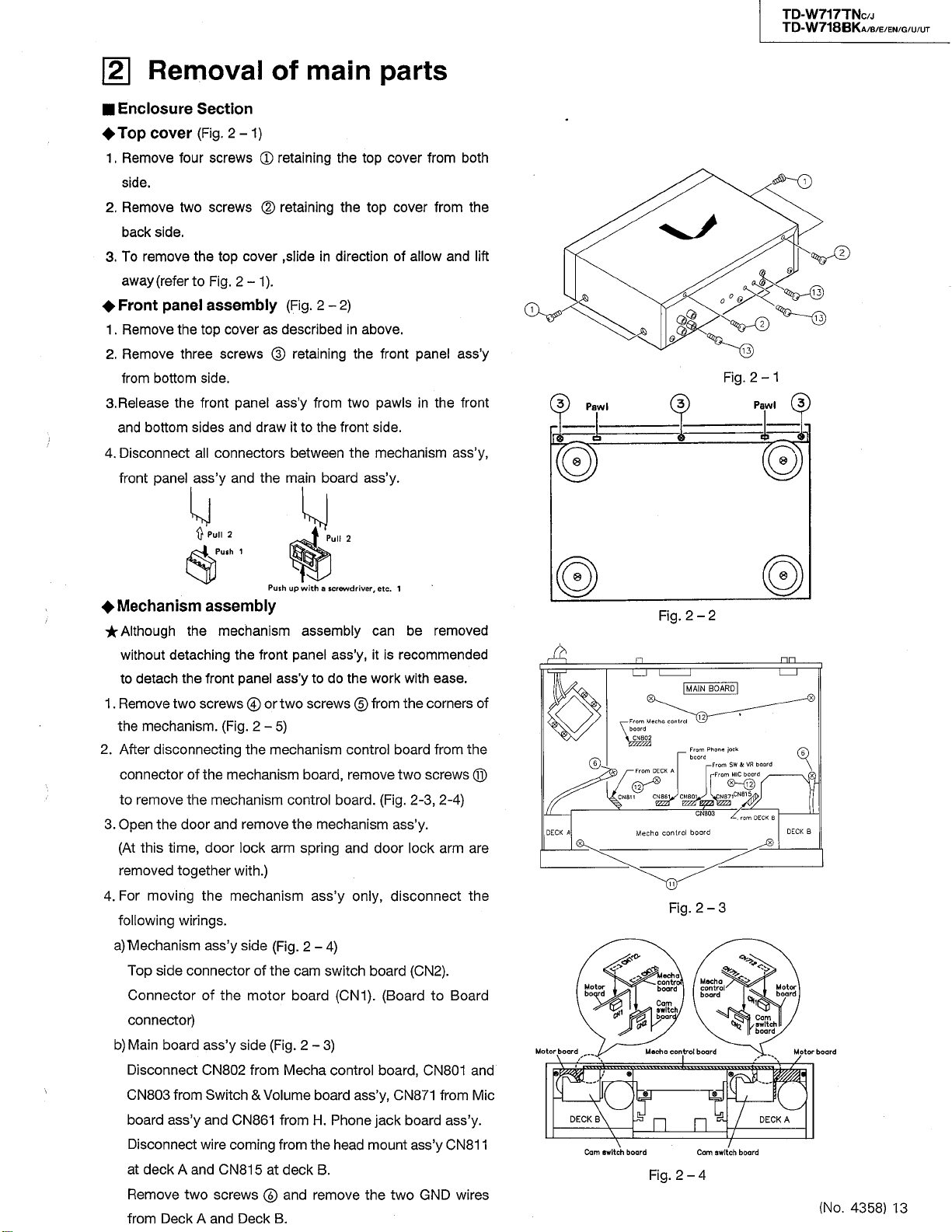
TD
TD
W
717
-
718
W
-
TNC
BKA
/
J
/
/
/G/U/
EN
B/E
UT
\2\
Enclosure
Top
Remove
1
.
side
2
Remove
.
back
remove
To
.
3
away
Front
Remove
1
.
Remove
2
.
from
Release
.
3
and
bottom
4
Disconnect
.
front
Removal
Section
(
Fig
2
.
cover
.
side
(
refer
panel
bottom
the
panel
four
two
.
to
the
three
sides
N
-
screws
screws
top
the
Fig
2-1
.
assembly
cover
top
screws
side
.
panel
front
and
all
connectors
y
ass
and
’
}
Pull
2
1
cover
)
1
<
£
©
as
draw
the
)
.
of
main
)
retaining
retaining
,
slide
(
.
Fig
described
retaining
©
ass
y
’
to
it
between
main
in
2
from
the
board
-
parts
top
the
top
the
direction
2
)
above
in
the
pawls
two
side
front
the
mechanism
ass
cover
cover
of
front
y
.
’
.
.
from
allow
panel
in
from
and
the
both
ass
front
ass
the
lift
’
Q
,
y
’
Pawl
o
,
y
3
Fig
13
1
2
.
-
Pawl
Mechanism
Although
without
detach
to
Remove
.
1
mechanism
the
2
After
disconnecting
.
connector
remove
to
.
3
4
Open
this
At
(
removed
For
moving
.
following
)
a
Mechanism
Top
Connector
connector
b)Main
Disconnect
803
CN
board
Disconnect
deck
at
Remove
from
the
side
board
Deck
assembly
the
detaching
the
front
screws©or
two
the
of
the
mechanism
door
,
door
time
together
the
wirings
ass
connector
of
)
ass
CN
from
Switch
ass
y
and
’
wire
A
and
two
and
A
Push
mechanism
the
front
ass
panel
Fig
(
.
.
5
2
-
the
mechanism
mechanism
remove
and
arm
lock
)
with
.
mechanism
.
y
side
of
motor
side
from
&
CN
861
coming
815
Deck
Fig
(
the
Fig
(
Volume
at
©
B
’
the
y
’
802
CN
screws
up
with
assembly
panel
y
’
two
)
board
control
the
spring
2
.
cam
board
.
2
Mecha
from
from
deck
and
.
a
screwdriver
ass
y
’
do
the
to
screws
©
control
,
remove
board
mechanism
and
ass
only
y
’
)
-
4
switch
CN
(
1
3
)
-
control
ass
board
Phone
H
.
the
head
.
B
remove
,
etc
.
1
can
be
,
is
recommended
it
work
with
corners
the
from
board
screws
two
3
(
Fig
.
.
2
-
ass
y
.
’
door
lock
,
disconnect
board
CN
(
).(
BoardtoBoard
,
CN
board
,
CN
871
y
’
jack
board
ass
mount
the
two
GND
removed
ease
.
the
from
©
-
)
,
4
2
arm
are
the
)
2
.
and
801
Mic
from
y
ass
’
y
CN
811
’
wires
2
2
-
Fig
.
A
n
BOARD
MAIN
nn
of
From
Mecho
control
Boord
,
02
CNB
A
From
DECK
12
y
86
CN
CN
'
A
DECK
Mecho
control
Fig
a
loch
’
Motor
board
Motor
board
\
\
DECK
Cam
B
switch
.
control
board
Cam
switch
board
/
Mecho
control
\
board
Fig
2
.
From
board
8
Qy
boord
.
-
CN
^
2
Mocha
control
board
board
Cam
4
Phone
-
803
-
^
From
-
From
NS
3
i
%
switch
jock
SW
MIC
SH
71
CN
4
815
rom
.
board
r
board
6
board
VR
3
D
r
/
T
.
DECK
6
DECK
B
Motor
board
Cam
switch
board
Motor
board
/
DECK
A
(
No
.
4358
)
13
Page 14

TD
TD
-
717
W
W
718
-
1
.
1
.
2
.
.
3
4
.
/
TNC
J
/
/
UT
G
/
/
U
/
B
it
EN
E
arm
out
/
ass
two
.
BKA
Eject
Remove
pull
Mechanism
Remove
(
see
Remove
Insert
between
pawl
Remove
ass
engaged
(
see
Remove
ass
’
Fig
y
Fig
,
from
)
y
.
'
an
and
four
8
)
2
.
-
the
originary
the
draw
the
the
with
2
.
-
the
(
see
y
’
screws
holder
screws
damper
damper
the
arm
mechanism
door
the
)
7
eject
Fig
.
2
Fig
(
.
2
®
and
retaining
®
ass
-
)
screwdriver
(
and
damper
shaft
side
spring
)
7
-
)
5
-
retaining
door
y
(
for
easy
’
the
front
ass
of
the
holder
by
the
from
the
’
y
ass
mechanism
the
reassembling
the
or
panel
outwards
y
’
cassette
(
The
.
longer
lever
lock
eject
(
Fig
like
to
side
arm
ass
Fig
6
2
.
-
-
holder
in
to
disengage
see
Fig
(
.
holder
spring
door
)
.
mechanism
and
’
work
the
2
y
2
.
door
(
and
8
-
,
gap
the
-
®
0
)
DECKS
)
.
remove
How
to
)
6
is
©
Fig
damper
0
©
DECKA
2
5
-
.
u
Fig
2
.
6
-
Switch
^
board
1
After
.
following
Pull
out
2
.
Remove
3
.
board
4
.
Remove
the
Lift
5
.
to
the
(
603
CN
6
Disconnect
.
(
y
ass
’
Headphone
4
y
ass
’
1
.
After
H
.
wards
removing
Phone
move
Key
switch
Remove
1
.
y
ass
.
’
the
Do
2
.
Main
4
1
.
Remove
2
.
Remove
&
Volume
y
(
ass
Fig
’
removing
steps
INPUT
the
screws
five
.
one
screw
right
board
mechanism
604
CN
/
CN
)
702
CN
.
Fig
(
2
.
-
jack
while
pushing
it
.
board
screw
one
same
for
four
four
ass
screws
screws
board
2
.
the
,
upwards
)
.
602
jack
)
8
the
board
the
’
board
8
)
-
mechanism
volume
retaining
®
and
©
control
coming
board
Switch
ass
down
it
ass
(
DeckA
®
other
(
see
y
retaining
®
retaining
®
ass
’
knob
remove
to
remove
key
from
ass
&
Volume
y
and
’
toward
y
(
Fig
’
side
Fig
2
y
Mechanism
and
holder
.
the
Switch
the
it
board
Mechanism
y
and
’
jack
Mic
the
)
8
2
.
-
)
B
or
.
,
-
Fig
3
board
the
board
the
,
proceed
&
.
cap
since
connector
with
Mic
board
board
bottom
retaining
-
1
2
.
to
Volume
it
connected
is
control
jack
y
ass
’
ass
side
the
)
the
Control
to
P
board
board
,
pull
y
’
to
board
panel
rear
the
C
.
.
pins
the
out
re
spring
Shorter
CN
60
T
Mic
Key
the
Door
side
*
a
switch
door
jack
Switch
side
board
\
9
Fig
board
and
eject
Mechanism
Fig
2
.
702
CN
rd
CN
I
602
.
)
14
)
(
9
\
\
H
.
Volume
&
2
.
-
'
y
ass
-
&
L
9
Phone
board
8
spring
ass
7
CAP
T
8
jack
'
y
Mecha
l
o
board
Lock
lever
eject
©
control
o
Key
spring
boord
T
©
switch
board
How
to
engage
Cassette
Longer
door
O
O
w
V
7
3
-
®
®
©
-
Key
switch
board
.
14
(
No
4358
.
)
Page 15

TD
TD
TNC
BKA
/
J
/
/
/
/
G
U
/
B
UT
EN
/
E
-
W
717
718
W
-
Reassembling
•
Attach
.
1
screws
2
.
the
Put
on
the
3
Attach
.
screws
two
4
.
Engage
.
Install
5
6
.
Install
Attach
7
.
five
screws
Install
8
.
HooK
9
.
.
y
ass
’
Attach
10
.
two
screws
Cassette
procedure
Key
the
.
ass
door
panel
front
mechanism
the
.
door
the
damper
the
eject
the
the
Switch
.
the
mechanism
the
eject
Mecha
the
.
mechanism
switch
y
and
’
.
spring
(
Push
.
arm
&
Volume
spring
control
board
the
holder
properly
y
ass
’
ass
between
front
the
of
ass
’
mechanism
the
to
.
pawl
the
.
board
.
y
’
lock
board
section
y
ass
ass
panel
to
front
side
lever
the
holder
last
y
to
’
to
y
’
y
ass
’
panel
together
panel
engage
to
panel
the
mechanism
and
panel
the
with
ass
y
’
two
with
with
it
with
with
Mechanism
©
3
S
(
)
left
roller
Pinch
)
.
o
A
©
WF
o
o
-
Head
Fig
Pinch
mount
9
2
.
-
>
a
/
roller
Iright
Head
)
mount
Head
ass
base
y
’
,
Fig
Fig
2
(
Fig
.
-
2
-
.
pinch
and
9
the
9
pinch
three
the
pawl
11
-
assembly
screws
assembly
pinch
roller
hooking
the
pinch
.
retaining
©
(
and
it
roller
mount
Head
Remove
1
.
Pinch
roller
Remove
.
1
the
gaging
For
2
.
reengaging
\
i
to
Fig
.
2
head
,
Fig
roller
2
io
-
.
2
roller
)
mount
11
-
spring
ass
)
by
spring
y
.
’
disen
,
refer
-
10
2
.
-
Fig
Pinch
roller
(
)
left
Pinch
roller
spring
Pinch
(
right
Pinch
spring
roller
)
roller
(
No
.
4358
)
15
Page 16
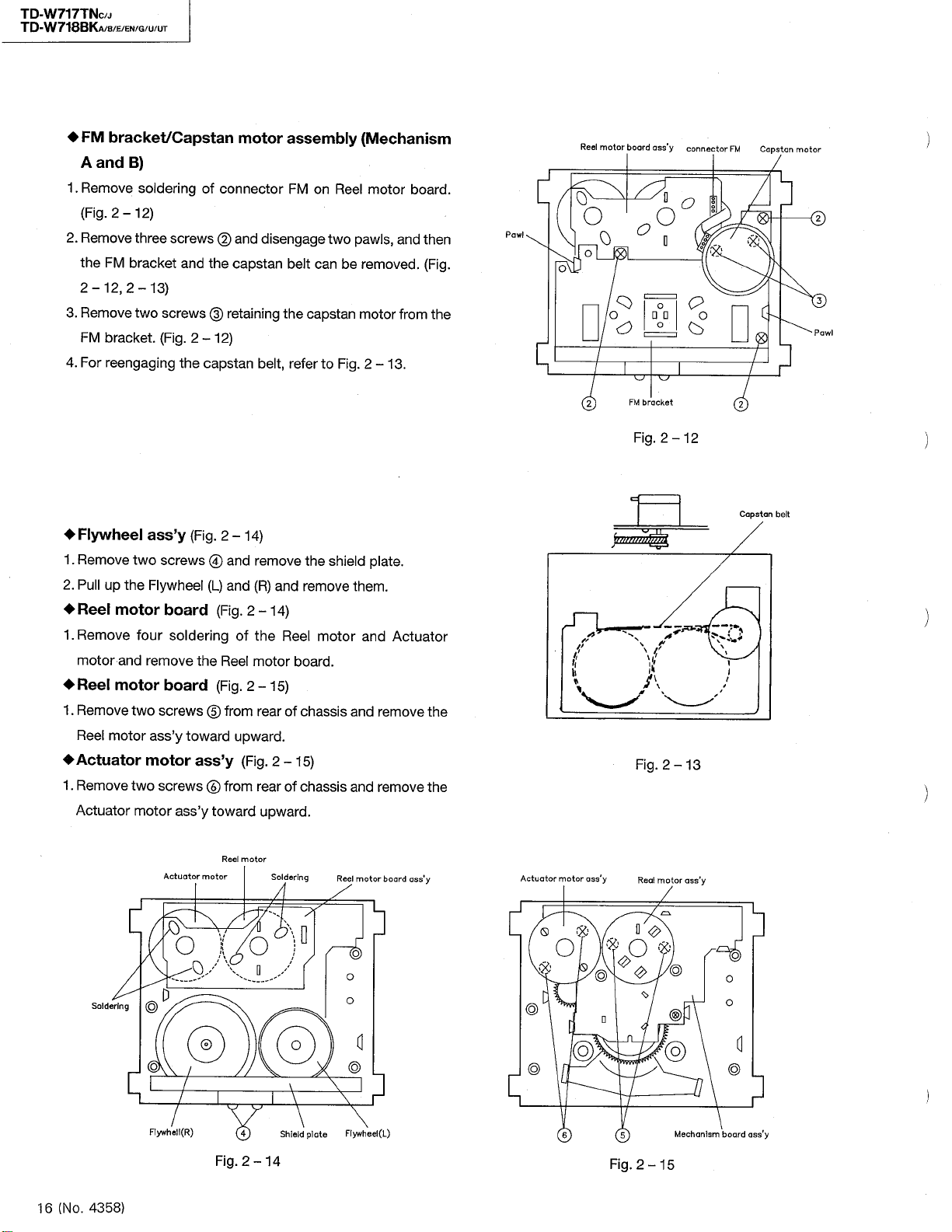
TD
TD
/
TNC
BKA
FM
A
Remove
1
.
Fig
(
2
.
Remove
the
2
-
Remove
3
.
FM
4
.
For
J
/
/
E
8
/
/
/
EN
G
bracket
and
)
B
soldering
2
.
-
12
three
FM
bracket
,
12
2
-
two
bracket
reengaging
/
UT
U
Capstan
/
)
screws
)
13
screws
(
Fig
.
and
.
the
2
of
connector
and
©
capstan
the
retaining
©
)
12
-
capstan
motor
disengage
belt
assembly
FM
on
Reel
two
belt
can
the
capstan
,
refer
to
(
Mechanism
motor
pawls
be
removed
motor
Fig
2
.
-
,
13
board
and
from
.
.
then
Fig
(
the
board
ass
'
y
connector
FM
Capstan
motor
Reel
motor
/
.
.
Pawl
d
o
O
_
0
J
O
o
FM
2
Fig
o
bracket
.
O
o
vZ
2
^
?
c
0
o
7
12
-
l
I
2
©
Pawl
-
717
W
718
W
-
Flywheel
1
.
Remove
2
.
up
Pull
Reel
Remove
1
.
motor
Reel
Remove
1
.
Reel
Actuator
Remove
.
1
Actuator
Soldering
two
the
motor
and
motor
two
motor
two
motor
d
ass
screws
Flywheel
board
four
soldering
remove
board
screws
ass
motor
screws
Actuator
0
y
’
y
toward
’
ass
O
-
Fig
(
the
ass
’
0
y
motor
.
2
-
and
@
L
)
(
and
(
Fig
Reel
(
Fig
from
©
upward
y
’
from
©
toward
Reel
l
/
I
/
M
/
.
of
.
(
motor
14
2
2
Fig
O
)
remove
)
(
and
R
)
-
14
the
Reel
motor
)
15
-
rear
of
.
2
.
-
rear
of
upward
Soldering
/
the
remove
board
chassis
)
15
chassis
.
\
D
i
/
/
/
shield
motor
.
Reel
them
and
and
motor
©
plate
.
and
remove
remove
board
.
Actuator
the
the
y
ass
’
Actuator
d
Capstan
belt
Fig
ass
'
y
motor
3
&
<
o
Real
0
?
r
O
<
>
/
\
2
v
<
©
0
13
2
.
-
’
ass
y
motor
g
>
<
)
'
/
L
.
f
©
>
js
?
o
o
®
16
(
No
.
4358
d
©
\
(
)
Flywheli
R
Fig
)
Shield
plate
14
2
.
-
Flywheel
(
L
)
6
5
Fig
Mechanism
.
15
2
-
©
board
ass
y
'
Page 17

Mechanism
Remove
1
.
Release
2
.
gearing
3
For
.
the
see
board
one
screw
the
Mechanism
between
magnified
y
ass
’
retaining
®
board
the
Mechanism
illustration
(
in
Fig
from
the
a
2
.
circle
16
-
board
five
board
.
)
.
pawls
and
.
Control
cam
j
TNc
BKA
/
/
UT
G
8
/
/
U
/
/
/
E
EN
Mechanism
board
ass
-
W
TD
717
TD
W
718
-
’
y
,
Pawl
(
-
Fig
2
control
the
to
@
)
(
position
b
actuator
upward
actuator
upward
the
gear
gear
.
cam
control
position
A
and
(
large
Control
B
A
of
gear
.
gear
.
(
small
Control
Release
.
/
1
For
2
.
control
groove
(
18
-
Actuator
Release
1
.
/
move
Release
2
.
move
Actuator
After
1
.
and
(
large
/
cam
the
assembling
cam
to
)
)
gear
the
toward
it
the
it
toward
gear
removing
actuator
)
.
Actuator
17
from
B
)
(
2
cam
of
Head
(
small
(
A
(
B
Fig
.
cam
)
Actuator
18
-
two
,
Pinch
base
small
small
2
-
,
,
remove
pawls
(
a
fits
lever
shaft
)
Fig
(
.
from
)
)
from
)
17
actuator
gear
.
)
2
one
the
(
zone
one
Fig
2
.
groove
(
and
Fig
(
.
.
)
-
17
pawl
pawl
gear
Actuator
)
17
-
of
)
(
)
zone
b
2
A
17
-
and
and
(
small
re
re
,
2
-
-
)
Fig
gear
b
zone
)
,
7
2
.
16
-
o
Actuator
(
small
gear
)
zone
Control
cam
side
)
(
chassis
P
lever
lever
Pinch
B
Control
17
cam
Head
base
shaft
Fig
Pinch
18
2
.
-
(
No
.
4358
)
17
Page 18
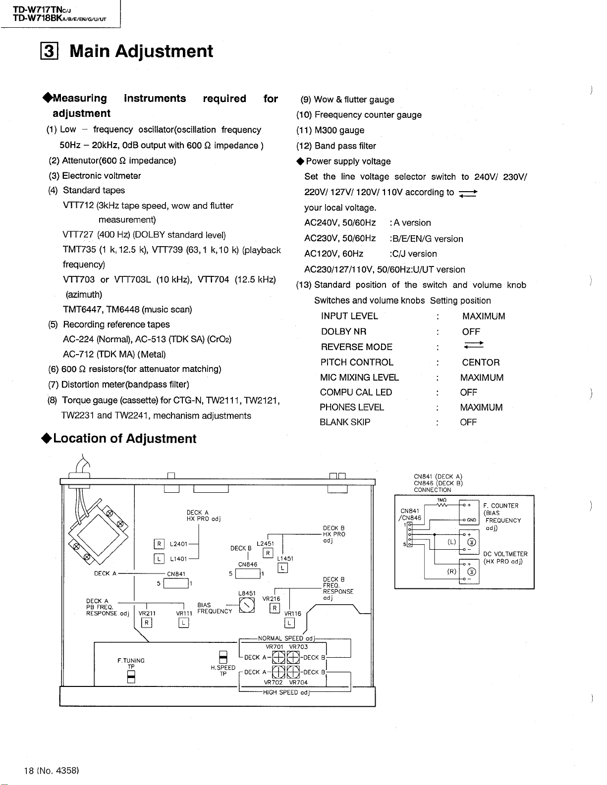
TD
TD
-
W
W
-
717
718
[
3
TNC
BKA
]
/
J
E
B
/
/
/
/
EN
G
U
/
Main
UT
/
Adjustment
Measuring
adjustment
1
(
2
(
(
3
(
4
(
5
(
6
(
7
(
8
-
)
Low
50
Hz
)
Attenutor
)
Electronic
)
Standard
VTT
712
VTT
727
TMT
735
frequency
VTT
703
(
azimuth
TMT
6447
)
Recording
-
AC
224
-
AC
712
Q
)
600
)
Distortion
Torque
)
TW
2231
-
resistors
instruments
frequency
,
20
OdB
kHz
Q
600
impedance
(
voltmeter
tapes
(
3
kHz
tape
measurement
(
400
(
1
k
Hz
,
12.5
)
)
VTT
or
703
)
,
TM
6448
reference
,
Normal
TDK
MA
meter
(
TW
)
)
for
(
bandpass
(
cassette
2241
(
(
gauge
and
oscillator
output
speed
)
(
DOLBY
)
,
VTT
k
L
(
music
tapes
513
AC
-
(
Metal
attenuator
)
,
mechanism
with
)
wow
,
standard
739
kHz
(
10
scan
TDK
(
)
filter
for
required
(
oscillation
600
and
(
,
63
1
)
,
VTT
)
)
SA
matching
)
,
CTG
N
-
adjustments
frequency
Q
impedance
flutter
level
)
,
k
10
k
704
)
(
CrOa
)
TW
2111
(
playback
)
12.5
(
,
TW
for
)
kHz
2121
&
)
(
Wow
9
)
(
10
)
(
11
)
(
12
Power
Set
220
your
AC
AC
AC
AC
)
(
13
)
Standard
,
flutter
Freequency
gauge
M
300
Band
pass
supply
line
the
127
V
V
240
230
120
230
Switches
/
local
,
50
V
,
V
50
,
60
V
127
/
INPUT
DOLBY
/
voltage
/
/
Hz
110
/
and
LEVEL
NR
REVERSE
PITCH
CONTROL
MIXING
MIC
COMPU
PHONES
BLANK
SKIP
gauge
counter
filter
voltage
voltage
120
V
.
60
Hz
60
Hz
,
V
position
volume
MODE
LEVEL
CAL
LED
LEVEL
/
50
110
gauge
selector
V
A
:
version
:
E
B
/
:
C
J
/
Hz
60
/
of
knobs
switch
according
G
/
/
EN
version
:
UT
U
/
switch
the
Setting
to
version
version
and
V
240
to
*
volume
position
MAXIMUM
OFF
>
CENTOR
MAXIMUM
OFF
MAXIMUM
OFF
/
230
knob
V
/
i
Location
DECK
DECK
FREQ
PB
RESPONSE
of
Adjustment
A
A
.
VR
211
adj
0
TUNING
F
.
TP
B
0
0
-
DECK
-
DECK
ad
adj
;
nn
DECK
HX
adj
DECK
FREQ
RESPONSE
adj
-
B
B
PRO
.
B
B
o
A
DECK
HX
adj
PRO
I
2451
2401
L
1401
L
841
CN
5
VR
111
1
BIAS
FREQUENCY
0
0
H
.
SPEED
TP
DECK
5
CN
L
^
-
-
B
846
8451
\
V
DECK
DECK
L
0
1
VR
216
0
NORMAL
VR
701
A
-
Hffl
-
A
702
VR
HIGH
1451
L
0
VR
0
SPEED
SPEED
VR
VR
116
703
704
CN
CN
CONNECTION
841
CN
846
CN
/
1
5
841
846
(
DECK
(
DECK
1
MO
AA
A
)
)
B
O
-
/
V
+
F
.
COUNTER
BIAS
(
•
o
GND
FREQUENCY
)
adj
o
+
)
(
L
®
o
-
DC
VOLTMETER
PRO
HX
(
o
-
+
(
)
R
®
o
-
—
adj
)
18
4358
.
)
(
No
Page 19

TD-W
TD
W
-
717
718
TNC
BKA
/
J
/
/
/
G
U/UT
/
E/EN
B
Compu
CAL
F
.
Short
1
.
2
Before
.
the
3
.
Press
At
NOTE
:
Item
Level
meter
sensitivity
adjustment
-
Calibration
mode
the
set
factory
the
the
same
Compu
When
played
If
Compu
on
the
Then
correct
setting
TUNING
F
.
.
the
CAL
F
setting
POWER
time
on
the
Calibration
-
counter
Mode
:
deck
at
Test
siganl
400
Hz
lnput
:
LINE
procedure
TP
and
mode
level
.
key
while
,
[
CAL
F
.
Calibration
-
counter
FL
of
the
error
Condition
EC/PAUSE
R
B
level
or
kHz
1
(
IN
for
F
GND
,
press
pressing
]
mode
is
FL
of
is
finished
indicator
message
:
4
,
dBs
-
and
L
R
.
CAL
on
mecha
the
Counter
the
displayed
is
finished
indicator
abnormally
.
and
)
mode
control
[
FF
normally
.
readjust
Supply
.
1
dBs
4
-
Press
2
.
sensitivity
3
.
Confirm
automatically
(
board
key
Reset
on
the
,
[
COMPU
]
deck
,
[
COMPU
the
Compu
a
400
key
while
of
B
-
CAL
Hz
.
the
[
COMPU
automatically
difference
that
adjustment
ass
y
.
’
pressing
deckAunder
counter
CAL
-
-
Calibration
or
of
]
LED
LED
]
blinks
Adjustment
signal
kHz
1
]
CAL
key
-
.
level
the
STOP
the
indicator
FL
light
up
and
.
both
to
deck
of
between
)
of
deck
key
power
standby
.
and
result
numberofcalibrationisdis
numberofcalibration
error
L
RofLINE
and
B
adjust
,
the
and
left
righkt
B
by
mode
level
reason
IN
meter
within
of
.
terminals
0.3
cancellation
is
displayed
at
dB
.
-
Playback
adjustment
decks
A
and
Recording
charactor
adjustment
(
Bias
and
REC
/
PB
sensitivity
at
decks
and
B
level
)
A
at
B
Direction
A
and
NR
:
OFF
Test
tape
Direction
and
A
B
Recrding
-
AC
224
AC
513
-
-
AC
712
OFF
:
NR
:
FWD
B
)
:
:
FWD
)
tape
(
normal
(
Cr
(
metal
VTT
02
(
decks
-
727
(
decks
:
)
)
)
1
.
Load
Press
2
.
3
Press
.
levels
Load
1
.
.
Press
2
charactor
After
While
.
3
Load
same
Afer
Load
.
4
same
After
NOTE
the
VTT
[
the
PLAY
[
the
COMPU
of
both
the
AC
[
the
COMPU
adjustment
while
about
adjusting
the
AC
manner
while
about40seconds
the
AC
manner
while
about
When
;
range
recording
of
test
727
-
key
]
CAL
-
decksAand
-
224
tapes
CAL
-
50
seconds
,
confirm
513
tapes
-
above
step
712
tapes
-
above
step
40
seconds
the
start
tape
tapes
of
deckAand
key
]
B
both
to
key
]
deck
of
that
both
to
.
2
,
to
both
.
2
each
and
end
both
to
of
automatically
of
,
all
adjustment
,
decksAand
playing
deck
and
A
.
decksAand
,
deck
and
A
adjustment
segment
decks
decksAandBand
adjusting
tapes
A
then
,
do
winding
start
deck
is
is
A
and
completed
is
completed
is
not
positions
displayed
.
B
back
the
adjust
the
B
.
recording
the
automatically
B
completed
adjusting
B
and
adjusting
use
while
.
.
tape
playback
.
automatically
on
indicator
FL
the
as
automatically
as
the
automatically
about3minutes
.
.
.
.
(
No
4358
.
)
1
18
-
Page 20

TD
TD
TNC
J
BKA
/
/8/
/
/EN/
UT
/
6
G
U
717
W
-
718
W
-
If
following
conditions
case
In
1
.
(
Error
01
ER
02
ER
ER
03
case
2
In
.
04
ER
05
ER
ER
06
3
case
In
.
For
(1)
Lch
12
ER
13
ER
14
ER
ER
15
ER
16
17
ER
18
ER
19
ER
No
error
and
the
.
the
the
messages
readjust
Level
) (
Contents
No
Over
Over
Playback
No
Over
Over
Recording
No
No
No
Can
Over
Over
Too
Too
the
meter
sensitivity
signal
the
the
level
playback
the
the
signal
400
Hz
12.5
kFlz
playback
find
not
the
adjustment
adjustment
the
much
much
are
indicatedontheFLindicator
Compu
of
adjustment
adjustment
-
the
message
adjustment
Calibration
adjustment
range
range
.
.
)
,
much
too
,
much
too
/
signal
adjustment
adjustment
test
test
signal
the
large
small
range
range
adjustment
signal
for
for
signal
Do
(
recording
range
range
kFlz
12.5
12.5
kFlz
,
too
,
too
.
recording
recording
not
recrded
start
of
400
of
400
playback
playback
much
much
large
small
large
small
)
position
Flz
playback
playback
Flz
signal
signal
the
the
the
the
level
level
when
input
input
playback
playback
signal
signal
compare
compare
adjusting
signal
signal
signal
signal
,
level
too
level
,
too
with
with
the
level
level
400
400
Conpu
much
much
Hz
Flz
large
small
signal
signal
-
Calibration
400
Flz
Flz
400
,
correct
playback
playback
these
signal
signal
abnormal
(2)
(3)
For
ER
ER
ER
ER
ER
ER
ER
ER
For
ER
ER
22
23
24
25
26
27
28
29
30
31
Rch
Lch
and
No
No
No
Can
Over
Over
Too
Too
Rch
Compu
finished
Compu
finished
400
Flz
test
12.5
playback
not
much
much
test
kHz
signal
the
find
the
adjustment
adjustment
the
large
small
-
CalibrationofAC
Calibration
-
signal
signal
(
Do
recording
12.5
kHz
12.5
of
for
for
not
range
range
kHz
AC
recording
recording
recorded
start
position
of
400
of
400
playback
playback
513
adjustment
-
adjustment
712
-
)
playback
Hz
Hz
playback
signal
signal
level
level
is
is
signal
signal
compare
compare
started
started
level
level
with
with
before
before
,
much
too
,
much
too
400
Hz
400
Hz
adjustment
adjustment
large
small
signal
signal
of
of
400
400
AC
AC
Hz
Hz
224
-
224
-
playback
playback
complete
is
not
complete
is
not
signal
signal
18
(
No
2
-
4358
.
)
Page 21

TD
TD
TNC
BKA
/
J
/
B
/
/
/
/
G
U
UT
/
EN
E
-
717
W
718
W
-
Mechanism
Item
Adjusting
Head
azimuth
Adjusting
speed
Tape
(
motor
speed
Adjstment
Conditions
Test
tape
After
1
.
normal
of
)
then
speed
high
For
2
.
adjustment
deck
and
between
TP
and
Do
.
3
not
while
TP
and
shortcircuited
Test
tape
VTT
704
VTT
:
12.5
(
adjustment
speed
high
adjust
.
speed
,
set
play
H
.
GND
anything
do
.
SPEED
GND
mode
SPEED
.
are
for
shortcircuit
H
.
:
(
3
712
-
kHz
the
kHz
)
,
,
)
1
.
Connect
LINE
Play
2
.
3
Adjust
.
(
FWD
electronic
both
for
be
0
”
Repeat
4
.
modes
5
.
Confirm
deck
1
.
Connect
LINEOUT
Perform
2
.
and
Play
.
3
Adjust
4
.
Adjust
for
]
[
)
B
Adjust
5
.
After
adjust
(
deck
Difference
6
.
must
Adjustment
electronic
an
terminals
OUT
back
the
VTT
the
head
and
REV
voltmeter
channels
)
.
”
adjustment
the
well
as
difference
that
deck
and
A
frequency
a
terminals
normal
do
then
back
high
the
normal
for
(
701
VR
normal
high
for
adjustment
702
VR
)
for
}
B
\
in
than
less
be
VTT
deck
speed
FWD
and
704
angle
)
until
phase
(
for
as
B
speed
speed
712
speed
speed
of
(
deck
high
48
.
becomes
within
.
A
[
speed
and
Hz
Confirmation
voltmeter
(
12.5
with
the
in
the
level
counter
adjustment
adjustment
test
)
and
]
3000
at
normal
Aj
[
REV
to
)
kHz
the
screw
reading
maximum
difference
and
FWD
decks
A
between
dB
2
.
the
to
tape
.
703
VR
.
Hz
speed
)
VR
and
6000
at
frequencies
test
and
.
the
of
must
first
.
(
704
Hz
tape
the
REV
B
,
deck
,
.
.
.
Standad
Maximum
Deck
F
Normal
Deck
15
High
Deck
30
speed
@
Hz
speed
0
Hz
W
,
,
1
1
value
,
A
:
3000
:
:
6000
:
Screws
(
B
ws
Deck
±
Deck
±
OdBs
Adjust
,
FWD
Normal
High
|
Normal
;
High
REV
0
;
§
VR
=
REV
:
;
VR
VR
;
;
VR
0.775
point
)
Adi
701
702
703
704
V
Checking
and
wow
flutter
Checking
back
play
torque
Checking
forward
fast
rewind
torque
%
0.17
than
and
less
WRMS
(
27
-
90
-
70
200
)
g
cm
-
cm
g
-
.
4358
)
19
(
No
wow
a
torque
FWD
[
,
or
the
(
REV
and
.
Play
see
to
0.17
%
testing
]
TW
/
remove
gauge
torque
manner
TW
:
)
2231
)
)
)
)
)
Connect
terminals
OUT
tape
.
Check
is
than
less
Employ
(
2111
TW
checking
a
torque
use
Measure
same
the
in
cassette
Test
TW
2241
a
Test
tape
:
kHz
3
(
712
-
VTT
Torque
Torque
/
TW
TW
TW
TW
gauge
2111
2121
gauge
2231
2241
(
FWD
(
REV
(
FWD
(
REV
flutter
back
if
the
(
WRMS
cassette
2121
the
.
the
in
in
as
(
meter
the
reading
)
.
[
REV
cassette
fast
the
FWD
VTT
712
of
tape
for
]
cover
forward
above
,
)
LINE
test
the
the
.
meter
mode
to
Page 22

TD-W
TD
W
-
717
718
TNC
BKA
/
J
/B/
/G/
E/EN
U/UT
Electrical
Item
Cheking
1
DOLBY
circuit
(
Rec
.
mode
(
BIAS
-
Item
*
Play
2
back
level
check
Playback
3
*
frequency
response
adjustment
Bias
4
*
frequency
adjustment
CUT
Adjustment
Signal
input
)
)
Output
pin
.
Conditions
Test
tape
727
VTT
tape
Test
735
TMT
739
VTT
Tape
:
Mode
:
Frequency
Input
more
(
pagel
See
[
Deck
B
CN
TP
:
Deck
0
TP
CN
:
:
LINE
-
dBs
8
terminal
400
:
Hz
kHz
1
:
12.5
/
kHz
1
:
63
/
Metal
REC
counter
impedance
MQ
1
than
)
8
]
846
pin
841
pin
Procedure
Cal
.
IN
kH
NR
:
2
:
IC
Play
OUT
Difference
than1dB
Play
VR
so
0±0.5
Then
that
Connect
[
B
deck
(
counter
TP
Hz
.
1
1
level
:
831
@
Adjustment
back
-
is
4.5
back
(
deck
216
that
deviation
dB
,
play
deviation
]
)
and
{
B
reads
Check
,
400
Hz
(
&
)
§
727
VTT
dBs
between
at
LINE
TMT
735
¥
[
]
(
deck
back
of
frequency
CN
841
)
and
\
95
DOLBY
DOLBY
.
Check
±
OUT
test
)
and
of
12.5
A
VTT
63
Hz
counter
(
deck
8401
L
kHz
and
B
(
)
Rec
C
(
)
Rec
and
Confirmation
that
dB
1
.
Lch
and
.
,
tape
VR
111
kHz
)
and
0
±
test
739
to
kHz
1
to
)
[
]
A
(
deck
.
Adjustment
Input
Frequency
(
,
1
cal
kHz
5
kHz
1
kHz
kHz
1
5
kHz
1
kHz
the
Rch
and
,
VR
to
0.5
is
the
and
[
that
tape
]
A
level
must
adjust
211
dB
2
+
CN
adjust
)
so
(
deck
of
(
deck
to
±
846
3
at
be
VR
1
confirm
that
signal
.
,
Cal
,
Cal
,
Cal
,
Cal
,
Cal
LINE
116
kHz
dB
deck
(
8451
L
,
-
.
less
[A]
B
.
the
level
40
-
.
.
-
.
-
.
,
)
is
)
.
)
dB
dB
20
40
20
Standard
LINE
4.5
dBs
-
Phone
14.5
-
dB
2
±
with
12.5
as
reference
0.5
0
+
(
deck
0±0.5
deck
(
1
kHz
63
Hz
2
±
+
95
kHz
kHz
OUT
Out
dBs
[
A
[B]
(
check
3
dB
value
±
kHz
dB
]
dB
±
)
)
0.5
+
and
at
Output
5.7
+
3.5
+
16.2
2.9
+
1
dB
,
)
:
,
raise
deviation
dB
±
dB
±
dB
±
0
dB
±
dB
±
OdB
±
Adjusting
Deck
L:VR
:
R
Deck
L
:
:
R
Deck
\
L
8451
|
Deck
8401
L
2
1.5
0.5
i
2
2.5
1
@
@
VR
VR
B
Al
value
dB
dB
odB
.
dB
dB
VR
\
dB
}
116
216
111
211
20
Slave
5
*
oscillation
(
HX
adjustment
(
4358
No
.
PRO
)
.
Voltmeter
DC
|
TP
TP
]
A
CN
841
:
H
CN
846
:
Deck
)
Deck
This
step
frequency
a
Load
recording
.
1
Adjust
Adjust
tive
voltages
PIN
(
3
2
.
Adjust
Adjust
voltages
tive
(
3
PIN
must
adjustment
metal
mode
for
deck
L
1401
5
)
at
-
for
deck
L
1451
)
5
at
-
be
tape
.
and
of
Rch
and
of
Rch
[A]
CN
[
CN
performed
.
and
2401
L
841
.
]
B
2451
L
846
.
set
(
PIN
(
PIN
to
to
after
decktothe
the
minimize
4
)
at
3
-
minimize
at
)
4
3
-
the
respec
Lch
respec
Lch
bias
and
and
Minimum
-
-
Deck
L:L
1401
2401
R:L
DeckH
L
:
L
1451
L
2451
R
:
]
A
[
Page 23

TD-W
TD-W
717
718
TNC
BKA
J
/
/B/E/
/G/U/
EN
UT
6
Item
Input
Conditions
1
sensitivity
level
:
dBs
:
2
3
This
oscillation
Record
level
level
Playing
level
check
*
7
REC
frequency
response
check
/
PB
LINE
Ref
±
2
MIC
Ref
±
3
NR
INPUT
-
20
.
)
dB
INPUT
.
dB
20
-
)
dB
SWITCH
dB
LEVEL
-
(
40
level
(
-
86
OFF
:
dBs
levelofthe
8
Recording
/
1
playback
sensitivity
check
Maximum
9
out
\
check
10
Checking
record
put
/
playback
2
Suply
Rec
signal
1
2
distortion
Supply
.
20
at
-
dBs
8
-
Supply
.
nals
is
8
-
Confirm
.
right
3
dB
step
of
)
.
of
CQ
)
Q
C
/
>
C
o
a
.
ta
)
O
DC
0
Supply
.
nals
record
of
20
-
Confirm
.
when
cording
1
monitoring
.
levelatthe
Record
)
terminals
Play
)
output
value
Adjustment
kHz
1
a
,
dBs
.
kHz
a
1
”
66
at
$
dB
.
that
within
2
MIC
at
must
adjustment
the
1
20
dB
-
back
the
the
12.5
1
kHz
high
50
Hz
a
400
dB
.
that
LINE
.
signal
kHz
1
a
.
back
with
conforms
signal
confirm
signal
,
confirm
dBs
difference
dB
at
LINE
terminals
be
and
kHz
(
dB
20
recorded
kHz
signal
Increase
frequencies
Decrease
frequencies
1
signal
Hz
400
Hz
a
REC
level
OUT
to
mode
LINE
,
kHz
-
recorded
the
a
distortion
the
to
and
Confirmation
the
to
LINE
that
the
to
that
level
IN
terminals
.
performed
.
12.5
lower
signals
is
signal
.
In
in
-
'
'
12.5
kHz
the
to
signal
indicator
is
-
LINE
the
,
and
terminal
IN
dBs
20
meter
standard
LINE
MIC
LINE
between
after
signals
kHz
than
,
check
0
±
high
kHz
LINE
reference
at
should
dBs
28
terminal
IN
read
.
signal
,
part
to
value
terminals
IN
level
OUT
input
OUT
left
and
the
the
reference
that
dBtothe
2
Low
Appropriate
High
Frequencies
IN
turn
during
clipped
non
-
to
LINE
Check
see
.
termi
level
and
within
slave
the
at
the
bias
bias
termi
level
re
the
in
the
the
if
is
-
current
bias
current
-
on
-
IN
Standard
IN
LINE
20
dBs
:
-
dB
2
±
-
66
:
MIC
±
3
12.5
kHz
0
dB
2
±
higher
than
.
the
kHz
1
current
,
Normal
Chrome
:
Metal
“
dBs
28
dB
1
±
LINE
OUT
more
than5dBs
PHONES
more
:
OUT
-
than
16
:
Nornal
Less
than
Metal
02
Cr
/
Less
than
dB
level
level
,
dBs
:
dBs
2
Adjusting
:
.
%
:
3
%
11
Checking
signal
noise
recording
playback
to
ratio
)
1
Record
put
perform
Play
)
2
dBs
recording
electronic
conforms
1
kHz
at
by
disconnecting
non
-
back
the
recording
output
voltmeter
the
to
,
20
-
signal
recorded
output
for
.
standard
signal
dBs
from
recording
part
and
comparison
Check
value
,
Stop
the
.
Measure
.
the
see
to
.
the
terminal
the
-
signal
non
using
the
value
if
-
in
to
8
an
-
Normal
More
dB
Metal
More
dB
,
than
,
chrome
than
40
41
;
(
No
.
4358
)
21
Page 24

W
TD
-
TD"W
717
718
TNC
BKA
/
J
/B/E/EN/
/U/
UT
G
Checking
12
erasing
coefficient
Item
Conditions
)
1
Apply
terminals
)
Perform
2
dB
20
)
3
Era
Measure
)
4
erased
with
For
the
connect
and
the
Input
(
1
^
Adjustment
a
400
.
recording
$
e a
part
the
part
an
electronic
measurement
band
a
electronic
)
kHz
1
(
)
kHz
Band
pass
Hz
of
output
and
filter
,
the
pass
and
Confirmation
20
dBs
+
the
with
recording
difference
non
erased
-
voltmeter
using
filter
voltmeter
Tape
recording
(
erasing
Electronic
voltmeter
signal
signal
.
part
.
a
between
.
deck
)
the
to
enhaned
between
compare
to
metal
the
,
LINE
tape
deck
by
the
IN
,
Standard
More
than
dB
Adjusting
55
22
(
No
.
4358
)
Page 25

CQ
-
Cora
Blue
CHS
!
2
3
Z
2
To
Board
:
Mechanism
n
Mark
CM
1
:
J
t
90
!
613
CN
Q
&
Board
Ass
y
_
CNI
1
r
’
)
V
o
O
O
r
“
—
U/UT
Version
only
0
923
CH
EEEO
CM
CN
24
FW
901
:
Key
Switch
A
)
T
.
fc
•
I
A
n
m
Stand
u
ll
•
|
jCElCN
by
Indicator
CN
3
711
VWF
712
1227
FW
701
I
O
O
DO
>
s
Color
1
2
3
V
Board
Mechanism
Control
Board
Ass
y
’
J
4
FW
701
CN
722
5
6
Ep
702
o
_
nnn
|
CN
602
CN
jnfcj
CN
r
605
t
VWF
^
i
VWF
Switch
1207
^
1211
-
/
Volume
604
CN
^
14
-
Main
14
TTB
TTBV
Board
CN
Board
721
Ass
Cp
:
Key
B
Switch
p
nj
—
614
CN
:
Mechanism
B
~
y
l
PI
f
’
1
|
Board
Board
~
ICNI
r
J
701
CN
r
t
19
-
TTBV
603
CN
|
13
-
cpgoi
TTBV
J
VWF
1209
,
901
CN
QD
Cord
Brawn
Red
Orenge
Yellow
Green
Blue
Ass
are
y
’
shown
7
8
9
0
D
LT
n
below
Violet
Gray
White
Black
Pink
NO
00
Ml
3
CQ
o
O
3
3
o
o
3
(
/
)
21
o
CO
C
00
K
CO
Deck
Reel
|
~
CN
2
M
rr
1
FW
©
:
Capstan
A
FW
fZ
@
ywis
—
u
a
/
4
Board
=
.
H
Supply
.
P
4
^
l
7
>
901
ccg
-
Phone
)
to
Motor
Chassis
Jack
Board
VWSC
DeckAHead
VYSA
n
A
Motor
© ©
05-10
B
3-043
1
R
<
°
from
Deck
VWF
Ass
33
>
y
’
K
Ass
©
1205
©
:
B
)
y
’
§
<
>
A
Head
08
-
TTB
CN
802
1
o
871
CN
CN
811
CN
WF
815
1205-08
from
Deck
TTB
B
\
Head
Capstan
Deck
6
>
<
)
i
r
872
CN
CN
2
FW
1
Motor
B
Head
VYSA
Mic
Deck
B
Reel
Motor
I
]
E
£
f
)(
©
y
Ass
’
1
3-043
R
)
cCo
Jack
Board
y
Ass
’
©
HH
DO
t
ai
I
>
>
00
can
o
>
<
ro
-
m
m
z
o
c
J
5
Page 26

TD-W
TD-W
717
718
TNC
BKA
J
/
/EN/
U/UT
/
/
B/E
G
24
[
H
A
B
c
D
E
F
G
(
No
Block
i
ru
w
Hs
§
o
(
QH
J
)
4358
.
Diagram
1
H
t
t
(
23
_
2
a
cu
1
<
6
B
«
m
s
8
0
0
Z
B
a
.
0
1
)
8
s
ff
-
r
m
(
S
JL
2
§
£
H
•
f
'
<
3
CD
a
CD
a
3
>
J
-
n
*
*
5
3
*
3
ia
—
*
^
^
^
oo
‘
5
5
*
»
>
<
5
S
5
S
u
H
!
)
a
§
*
V
_
5
S
cr
3
?
u
s
S
B
KMX
n
ID
*
«
s
CD
oL
—
0
u
K
im
10
a
8
CD
0
r
t
s
ca
a
I
d
2
5
£
»
fe
-
HXMsKE
<
\
i
C
3
iLL
S
f
CM
)
£
S
i
i
i
i
ID
n
<
8
.
I
D
CD
-
CO
V
fU
a
z
I
_
)
n
§
a
x
<
/
»
*
C
«
-
si
£
III
sH
I
5
!
J
O
?
CD
a
<
$
)
®
—
C
o
—®—
c
Si
(
*
S
i
<
is
X
K
fe
ID
n
^
o
cn
n
^
25
ss
§
5
s
]
TIT
0
J
cc
-
_
2
a
L
>
nif
*
8
fc
-
lsd
2
2
Cl
a
2
-
i
:
aj
a
D
<
i
M
2
cj
8
v
(s)
Cg
—
a
n
«
>
>
«
«
*
*
*
?
53
M
OJ
*
*
II
8
3
§
CD
0
K
<J>
5
0
5
_
S
=
!
Sm
=
5
d
0
2
Q
1
-
—
1
^
i
3
s
2
S
0
3
J
{
KMI
M
-
B
2
05
-
0
0
*
H
J
S
a
t
£
f
d
.
5
Fig
X
1
-
4
5
*
d
5
I
W
’
Sri
-
mo
03
d
m
)
ino03d
Id
CD
/
d
03 03
e
HI
Ui
*
0
1
-
si
Q
5
£
a
a
d
H
>
8
R
CD
"
fi
8
a
s
s
rrrrm
0
P
•
?
\
f
i
9
?
U
88
i
o
s
J
111
-
J
e
*
fy
3
4
@
9
.
9
Ifl
•
0
*
8
t
CC
a
_
i
2
XK
g
y
g
0
G
&
>
3
r
*
Q
Page 27

Page 28

TD-W
TD
W
717
718
TNC
BKA
J
/
/
/
B
UT
/
G
/
U
/E/
EN
Standard
®
A
B
c
D
E
F
G
VDH
:
Note
1
2
1
X
u
.
©©®©©
o
x
SLZ
2348002
)
—
SLZ
tr
?
5
w
(
VOH
To
on
(
Fig
POWER
RBOl
V
IK
-
-
981C09
B
Ei
B
15
TO
IN
DV
Schematic
ro
\
A
2
o
1
.
COMPU
A
CAL
606
D
©
981C09
.
0
COMPU
CAL
0
625
D
is
Q
y
%
la
CN
MAIN
2348
-
G
page
.
grab
BLANK
(
)
i
s
1
T
$
m
LED
F
-
LED
T
-
T
a
a
4
a
603
PWQ
-
0028
7
-
3
6
in
.
REC
A
610
S
610
R
wv
.
2
/
i
—
^
CN
VMC
CN
VMC
T
6
-
6
in
UJ
(
V
s
27
)
„
v
V
.
A
7
K
SKIP
^
603
02B0-0
is
VI
V
>
V
DIP
0611
NSLR
613
02
Al
)
<
B
!
S
)
/
r
LED
32
—
-
1
CAL
8
CAL
f
CN
VMC
2
o
yi
in
</>
4
«
BLANK
611
S
31
SMCT
5601
S
-
4
H
DSQ
11
06
S
DB
A
.
COMPU
606
S
OjO O
.
COMPU
625
S
605
-
0163
SEMICONDUCTOR
DTC
ES
124
SIRS
1740
SC
2
143
0
TC
ES
ES
124
DTA
ES
114
DTC
1175
SA
2
IHFE
in
m
m
i
e
co
/
in
n
SKIP
.
603
610
611
S
S
-
V
01
Z
-
A
W
.
5
PWB
KEY
VMW
1388
C
.
A
COUNTER
RESET
605
S
1
R
605
1
i
Wv
7
.
4
K
COUNTER
B
-
RESET
624
S
.
4
K
7
04
SS
S
-
VR
IT
VR
601
20
K
V
05
OVGA
12
Z
-
07
R
2
0704.0710.07
)
0701
Q
0744
0703
Q
)
Q
cv
in
in
IT
.
I
L
.
609
Diagrams
.
.
No
Ref
.
.
7
Q
Q
2
il
I
.
.
.
.
7
7
7
Q
Q
O
5
O
O7O
O
2
.
.
.
Q
7
Q
715.0716
721
740
A.PLAY
S
R
Wv
2.7
B.PLAY
S
2.7
S
Q
8
i
717
.
.
-
,
.
Q
0743
0742
741
-
o
KEY
604
O
i
—
604
K
623
K
623
S
~
55
.
+
6
\
SW
a
a
m
*
62
AAAA
ai
m
o
PWB
'
aS
©©©©
©©©©
ru
UJ
QSQ
B
VR
QVCB
I
Mk
i
Si
-
W
.
VMW
13
s
E
*
S
R
1
S
R
-
1.8
4
11
H
-
PHONES
603
16
A-V02M
®
i
©©©©©©©©
TO
IN
2340
IVDH
To
on
(
Fig
713.0714
.
7
7
Q
0
O
.
Q
719
720
.
0745
0
BB
It
©
©
©
©
o
5
.
FF
A
609
609
Wv
.
BK
B.FF
628
620
WV
K
V
01
Z
VR
22
KlA
jjh
801
CN
MAIN
-
OO
-
C
9
page
6
.
O
I
|
L
s
I
©
(
ft
I
*
}
4
)
PWB
-
3
.
Q
746
.
9
.
SLR
STANDBY
R
R
622
1
CNS
)
CN
VMC
—
—
yj
§
ru
M
2
BVI
27
)
-
01701
BJ
-
55
.
B
62
S
o
621
2.2
BK
-
604
0260-007
.
A
50
S
R
60
Wv
1-2
.
8
627
S
627
R
WV
12
VR
OV
.
5
.
£
361
VCF
VMW13BB
DIR
S
K
14
REW
B
B
K
REW
K
602
16
GA
\
I
G
LED
i
VMC
CN
VMC
5
SW
LEAF
VSH
L
u
til
3
.
708
fW
^
iS
Q
710
Q
714
O
Q
713
Q
712
0CS0
0
G
©
G
1
0
G
2
0
3
G
0
4
G
0
GS
0
6
G
®
)
.
a
tv
0
B
RESET
-
VFOP
J
9
16
S
(
13
515
S
14
513
3
S
12
&
S l l
©
10
S
9
S
)
9
&
8
S
S
7
6
S
ss
S
4
3
S
S
2
DATA
1
-
-
OATA
1
RESET
,
5
PE
ET
MDDA
xo
xo
XI
XI
VS
3
701
X
EFD
1
-
—
a
:
m
PWB
CONTROL
1170-001
8
R
R
CONTROL
MBS
UT
ECH
-
f
VMW
T
77
720
722
MOPE
T.P
004
BMHZ
-
13
1
IC
9146
vy
723
R
22
2
g
701
4
T
8
B
K
V
"
-
a
s
©
Sbi
MICON
-
V
P
152
2
METER-L
METER-R
DA
STANDBY
A
0716
F
.
T.P
B
|
AVcc
AV
KEYO
KEY
KEY
KEY
-
DA
DI
-
CLK
DA-LD
DAT
ATA
DATA
DAT
DATA
B-DATA
CLK
B
-
-
STB
B
DI
cs
osc
3
DATA
-
-
DATA
2
CLK
E
-
QCSIW
TUNING
7102
S
9
1
2
3
AO
I
1
2
3
A
4
SK
DO
I
I
I
MS
1
1
u
1
m
fj
®
r
m
m
m
m
m
M
£
3
0
vMC
‘
)
0
»
m
S
?
£
U
+
KEYO
^
1
KEY
DA-DI
ov
~
CL
0
V
DA
>
LO
0
DA
V
-
DATAO
v
0
DATA
1
V
0
2
DATA
ov
3
ATA
ATA
4
)
OAT
B
-
CLK
B
-
-
STB
B
SK
01
DO
cs
ByOSC
g
.
STANDI
OV
OAT
-
/
3
-
OATJ
2
CLK
E
-
MS
sv
DcslN
sv
VKS
QIR
.
15
2
V
-
3
2
1
SV
PC
PC
PC
2
5
o
g
CJ
2
B
3616
^^
©
©
©
©
©
©
0
©
3
©
2
/
O
m
“
MECHA
.
R
(
V
CM
pJ
g g
D
w
T
^
X
-
OIR
©
©
©
©
©
©
©
©
©
©
©
©
©
©
©
©
©
0
©
©
©
©
©
©
©
©
©
©
©
©
©
©
©
©
00
R
4
A
.
STOP
R
-
.
R
-
CASE
KEY
KEY
KEY
GNO
5
PCO
PC
PC
-
CN
VMC
CAM
P
/
MS
PLAY
©
a
370
Q
70
070
.
GNO
3
2
1
V
3
2
SREC
-
CLK
E
ME
!
OI
DA
—
CLK
-
DA
DA-LD
B-DATA
CLK
B
-
STB
B
-
MS
~
2
DATA
STANDBY
OSC
DATA
1
-
-
RESET
B
R
05
Et
.
6
V
5
V
5
IV
1
GND
D
—
GNO
M
—
V
24
-
POFF
FI
2
F
DCS
701
01
B
SW
PWB
B
IC
HALL
IC
HALL
A
DN6B51A
6851
DN
3
1X2
2
1
X
.
UJ
a
a
s
s
£
©
©
0
©
©
X
X
1
3
!
-
£
¥
1
0
©
@
©
t
J
U
ki
k
10
n
in
C
\
OJ
OJ
OJ
J
g
g
oga
Q
711
GO
s
N
J
7
i
'
T
N
/
/
/
/
/
-
R
3
27
S
ru
G
1
'
2
g
ID
g g
-
V
24
15
S
S
14
13
S
,
,
S
12
Sll
v
s
10
\
_
9
VS
8
S
^
S
7
\
6
S
\
5
S
'
4
NS
3
S
S
2
\
i
k
&
2
g
ru
-
RESET
B
T
S
6
8
T
T
¥
MECHA
3
A
VMW
1332
CAM
SW
n
.
F
.
STOP
F
/
MS
F.P
,
.
F
PLAY
CN
722
0234
VMC
P
-
mmmmm
ov
ft
1
0721
KEKD
B
0
|
|
£
PWB
G
L
.
629
S
622
SS
S
21
~
.
.
PAUSE
B
H
5622
S
o-o
DOLBY
.
REC
B
NR
629
S
~
f
—
J
I
4
}
4
—
VR
10
KIA
A
V
.
-
SS
'
R
629
reSO
f
4
Wv
—
4.7
K
2.7
02
07
S
1
B
—
.
A
STOP
&
07
S
R
607
vW
IK
.
STOP
B
626
S
|
R
626
1
\
W
IK
CONTROL
PITCH
)
VR
5
604
0
16
VGA
02
gf
*
QSQ
633
S
11
4
H
-
.
N
5.0
S
OUB
8
U
-
32
633
SG
K
27
.
MOPE
REV
.
SW
631
3
S
D
(
H
631
wv
-
wv
—
.
B
2
K
Cl
K
*
CASE-GND
KEY
KEY
KEY
KEYO KEYO
GNO
k
IBI
01
B-V
L
6
SW
VR
PWB
601
0163
09
R
-
To
on
(
Fig
6
Fig
.
1
-
KEY
1388
VMW
G
5
-
page
-
6
.
I
Bl
27
)
3
Page 29

-
718
W
/
UT
U
TD
-
BKA
/B/E/
UT
/U/
/
G
EN
/
J
TNC
717
W
TD
I
I
I
I
£
4
ING
32
WA
I
1
m
*
5
m
m
m
1
f
m
[
©
m
m
m
bj
rffi
m
m
?
V
5
ov
OV
OV
Ov
ov
ov
g
.
ov
sv
sv
.
-
iLN
S
KEYO
KEYl
KEY
KEY
DA
DA
DA
DATAO
OATA
DATA
DATA
DATA
B
B
B
SK
01
DO
CS
ByOSC
STANDBY
3
2
E
MS
OcslKI
-
-
-
-
~
-
8
u
2
DI
-
-
LD
-
OATA
CLK
STB
OATA
OAT
CLK
.
8
-
o
o
+
i
3
CLK
1
2
3
4
A
6
©
© ©©®
a
£
£
8
W
\
°
“
v
8
R
"
S
rAVv
Oh
2
720
>
Jo
i
i
!
m
719
22
v
<
?
K
R
"
CD
m
770
w
100
o
©
<
n
<
RA
701
QR
8045
,
2
3
.
4
5
>
\
R
771
*
wv
100
100
dXaXgXiv
^
O H I O
Q
D
AgXiXg
5
ov
704
C
|
—
1
0.01/16
?
V
?
?
8
m
Q
II
s
L
|
IA
11
7
X5X
S
6
8
<\<
H
(
EAI
1
IV
Et
»
MOTOR
^
s
)
REEL
ri
I
TT
(
i
.
9
2
A
TO
10
(
M
g
^
EC
75
3-3
JS
9
u
a
u
*
J
\
0234
VMC
0234
VMC
&
pg
VR
.
NOHM
—
3
K
DRIVER|B
OJ
sis
U
£
s
d
a
MOTOR
T
1
1
K
—
gfc
z
5
—
CN
A
-
-
2
'
DRIVER
£
L
<
CM
in
1
.
0
0
1
a
s
s
©
08
S
-
-
O
©
711
•••
P
08
-
8
12
AO
SPEED
HIGH
oJlo
asKi
1
10
KIB
701
,
SPEEO
ADJ
0744
V
732
IC
|
621
BA
fu
£
i
i
2
X3X4X5X6X7XBX
s
s
£
n
i
U
8
ul
6
6
IC
iBl
TAB
(
V
nj
S
§
5
>
>
(
5
]
2
?
X3X4X
X
>
&
3
u
i
.
D
t
\
°
R
-
l
.
734
WV
.
pjv
C
e
E
.
B
X
8
CD
736
409
2
I
1
©
J
§ §
6
>
S
.
?
6
BK
.
-
7
8
|
UJ
cl
=
©
i
m
R
742
9
s
u
6
S
fij
>
XeX
rl
I
d
—
—
rj
^
8
s
j
/
H
f
41
9
m
<
© ©
©
0
9
<
<
Si
3
PC
PCO
s
o
H
^
ii
'
CD
734
R
WV
—
3.3
K
2
M
a
g
2
'
IC
51
3
<
54
©
a
R
A
n
© ©
m
HALL
©
HlH
fils
N
0743
ill
0746
£
8
L
IC
'
0
J
_
SB
.
HIGH
B
751
R
.
110
15
1
10
’
752
R
10
’
HIGH
-
tr
<
TEST
V
3
6
-
SW
LEAF
1170-001
VSH
u
£
_
u
-
~
7
701
W
©
r
n
Q
717
|
)
0718
^
ADJ
SPEED
K
K
703
VR
.
SPEEO
B
NORM
SPEED
POINT
IC
BA
CVI
sis
IX2X3X4X5X6X7XBX
§
iui
d
<
UJ
ul
<
4
£
S
fT
.
fN
CM
cccv
a
s
V
9
2
-
)
lOKtS
E
.
ADJ
7101
B
0742
2
-
«
731
|A|
5218
u
2
§
§
s
n
o
8
ill
< < <
733
IC
409
S
TAB
cu
W
S
S
4
XSXSX
X2X3X
>
£
rf
v
>
E
<
II
cu
n
11
2
CAM
ftj
fc
-
5
R
73
w\wv
-
l.BK
7
3616
A
MECHA
R
S
R
.
g
10
I
-
7
PIR
QS
PORT
A
00
.
B
FI
R
S
K
7
n
R
73
EXI
R77B
B
7
C
702
IC
CAM
STOP
P
R
.
PLAY
TO
^
^
703
EXPAN0ER
SH
/
MS
uj
>
Se i
©
© © ©
S
Q
B
i
”
_
«
<
L
25
<
2
-
0.01
ii
M
50253
PWB
HALL
0
N6B
«
X2X
u
o
(
(
!
©
©
FN
15
R
R
Q
o
O
M
0738
0739
'
^
I
is
*
/
16
3
-
I
P
VMW
A
1332
CAM
SW
VKS
.
DIR
F
.
STOP
F
.
.
/
P
MS
F
PLAY
CN
721
VMC
0234
PUFF
-
J
6
B
2
2
7
P
?
Wv
R
3
?
?
Wv
R
100
7
?
WV
100
LO
8
!
o
2
^
CJ
W
a
>
.
712
CN
0
-
P
0234
15
VMC
B
P
-
SPEC
4
10
s
3
S
8
3
!
in
2
FW
1
§
<
l
—
7
5
9
:
YOX
XGX
X
X3XZXI
'
*
702
RA
5
B
QR
103
80
J
-
5
V
0704
ov
ur
§
&
tv
ov
1701
|
0703
'
s
3
'
R
711
WV
47
705
Q
IFW
K
70
R
B
.
K
2
7
SJ
?
xa
35
*
*
L
R
’
Mic
iZLPsrts
I
When
1
suretouse
Playback
Indicator
input
replacing
are
signal
signal
signal
safety
the
for
assurance
those
specified
parts
.
DECK
one
B
parts
make
.
Line
B
+
-
Line
B
-
-
f
.
(
No
.
4358
)
25
Page 30

TD
TD
TNc
BKA
j
/
/B/E/
/
EN
TI
/
TI
/
G
UT
U
717
W
-
718
W
-
1
A
A
P
fi
/
E.HEAD
|
<
VGH
0425
Lcn
333
ERASE
OS
Rch
5
B
A
R/P
6
E.HEAD
c
|
0425-542
VGH
D
E
HX
|A|
1402
R
Wv
R
<
spio
ml
ifi
ru
U
o
D
F
o
4
m
§
u
1
o
HH
ft ft
3
u
1
V
o
A
-
542
i
S
^
—
ASsT
'
PRO
-
g
I
T
17
VCLTAGE
REGU
-
LATCB
2
>
—
*
R
2402
WV
—
33
K
—
2
ST
n
m
~
S
5
^
IS
6
?
16,15
D
I
DET
I
3
(
>
•
2
£
s
]
K
E
—
?
a
25
I
®
@
f
T
(
Y
f
I
®
d
>
©
=
G
-
>
§
?
to
in
S
UJ
M
11
S
r
I
D
<
=
-
J
R
1401
WV
—
270
K
Cl
Hh
0.039
S
.
f
,
14
4
5
)—(
,
ft
?
C
Hh
0
R
2401
K
270
to
OJ
O
(
NJ
38
<->
o
J
2406
J
;
*
-
I
J
C
100
406
f
(
-
fr
039
C
^
;
!
I
!
i
;
:
i
i
!
!
!
i
I
»
•
o
1402
.
1
P
RXIIT
I I
L
?
i
3
I
J
e
)—(
r
I
P
100
”
=
®
s
B
7
:
If
V
^
8
in
V
VCA
)
—
l
p
|
!
i
!
-
L
Cl
22
L
o
C
(
o
sk
a
o
!
m
3
g
P
/
1
VRli
VR
.EQ.
A.PB
.
B-HEAD
VRl
o
6
?
2
cc
8
O
k
6
,
!
*
ffi
w
!
u
VRl
0
i
;
.
iv
r
.
.
pv
1201
^
150
206
^
par
.
2206
C
150
..
II
nj
?
8
ON
—
25
\
J
ft
4
i
10
.
1
,
A
CRulFi
a
9
(
)
—
i
jj
58
§
+
2
?
SI
a
a
8
glsl
ST
211
ADJ
AMP
|
16
O
-
r
^
^
lOOKtBl
J
'
'
VR
16
.PB.EQ.
IBmH
/
P
500
/
500
P
04
O
C
II
10
P
o
o
T
f
5
H
§
.
^
216
/
2
<
s
.
VR
ov
s
2
T
§
|
O
—
SI
sTs
K
100
216
ADJ
¥
2
+
o
nl
II
s
8
!
S
sf
U
02101
s
?
ICB
is
g
01
2
u
a
1
B
.
S
o
^
<
2
©
0
B
+
.
I
.
6557
4
HA
UPC
1330
I
'
fl
i
+
YaY
7
4
Y
5
9
Y6Y
g
g g g
a
s
SI
3
S
~
o
rn
~
u
a
g
ro
to
i
-r-
ns
—
xn
?
150
R
01O6
4
rWVi
100
4
00102
32
o
o
5
u
105
wv
k
22
Cl
0.012
*
42
\
o
\
+
2154
C
0.012
ov
F
1
1/2
IBfnjH
.
/
P
o
-
3
154
500
7
V
)
®
0
B
+
)
3
-
1155R1150
R
AAA
-
6-8
R
21551
4
|
R
I
AAA
270
)
,
f
K
I
02152
0
-
-
854
K
V
’
1
ov
§
8
T
ICS
17
AN
6557
/
Yl
21
WV
4.7
K
.
lo
S
£
70
B
in
ID
all
V
2
.
2150
R
T
^
251
LI
1256
C
F
—
IV
.
i c a i
ANS5S
(
1
o
o
vH
J f f l
u
s
o
o
6
5
n
a
o
a
(
\
1
0
l
i
-
812
IC
6557
AN
I
156
Cl
.
Sr
.
/
50
4
7
a
6
.
sv
O
ffl
K
s
u
EQ
V
1.2
o
1
H
'
—
6
S
2156
C
*
.
/
50
4
7
*
IBmH
/
5
.
150
R
.
QQ
?
Ji
88
2
7
F
/
21
hsJvS
U
:
8
,
1
A
—
ov
C
0.0 1 2
2
v
+
R
R
2
4
1
2104
C
0-012
ov
j
—
,
flu
.
©
^
F
I
1/2
-
iT
"
t
+
5
r
|
)
]
+
U
a
+
,
9
1104
R
Wv
?
2
1104
%
II
1109
47
2109
47
R
2105
4
K
2
-
5
±
8
ft
270
K
)
-
BJ
Jg
+
V
7
-
)
s
Sis
I
Si
a
?
si
p
.
.
|
j
|
HEAD
AM
B
7
8
«
5
?
Cl
106
1
/
4.7
50
3
1105
Wv
4
.
70
2
A
K
E
<
.
.
I
7
i
0
O
wL
MT
.
0
-
2
VT
R
1164
Wv
K
22
CVI
pv
#
5
®
Q
1151
02151
#
2
m
5
)
—
.
0
-
R
2106
AAA
3.3
2
V
V
I
-
7
7
vlv
)
}
U
Hi
2
—
—
(
A
(a)
2
<
>
—
.
SVT
0
-
VT
2
VT
.
£
0
-
3
J
v
4
RS
K
tv
V
>
.
i
C
2106
12
5
to
fe
*
*
.
/
4
50
7
s
H
4
G
21
WV
22
K
5
a
F
3
ICBll
iY2Y3Y
g g
I
s
,
•
*
*
*
2.6
V
2
•
-
s
if
*
$
HA
1330
16
UPC
I
gYs
a
)
a
m
)
V
.
1
I
'
I
\
g
I
*
g
g
g
g
|
R
0152
4
*
ViA
—
—
100
Q
8151
+
2
SZ
sf
s
i
0151
R
L
AAV
-
—
k
22
M
"
V
5
AN
i
T
f
;
.
Y
2551
.
-
C
2256
sli
ST
o
5
G
L
Playback
R
AV
:
VDH
2348002
Note
VMW
A
1307
PWB
JMAIN
signal
for
DECK
S
|
|
sI
mss
3
8
2S2
SS
|
L
B
sa
»
Playback
signal
DECK
A
for
L
Recording
R
Fig
signal
6
.
DECK
for
2
-
B
Page 31

TD-W
TD
W
-
717
718
TNC
BKA
J
/
/B/E/
/G/U/
UT
EN
SEMICONDUCTOR
DTC
ES
124
ES
DTA
124
IHJI
105
SK
2
1175
SA
2
lhFEl
(
2001
SC
2
OV
-
*
0BO6
22
k
ffs
OVTQ
8803
,
V
'
8
Ref
01101.02101.01102.02102.01151
.
00483.08801
0
.
Q
08101
8102.00151
00435
)
IA
105
SK
or
2
_
Kl
!
•
as
sai-ttMisii
m
-
AMP
sT
A
CB
805
If
0.022
y
o
01152.02152
.
08432
.
431
OB
492
0
B
-
-
3
8
IC
B
COMP
NF
ifs
-
C
0
s
6
CD
o
Q
QB
08O9
^
8482
1
If
.
.
.
441
ass
LA
GND
if
/
50
08443.08444
Q
2000
6
.B.
HEAD
AMP
jp
.
106
RTIOB
1107
/
7
50
70
A
E
<
1
0
V
I
-
7
1
.
o
SV
-
o
-
)
6
<
C
2106
.
4
/
50
7
R
K
3.3
l
0
2
vI
vl
vi
.
.
.
0
-
2
2
-
—
„
T
7
V
.
&
-
|
HSEQ
R
0
O
21
I
4.3
K
T
R
2107
1
AAA
*
K
1.5
m
i
<
08801
R
1110
m
4
.
SK
vi
.
0
2
i
f
7
V
|
-
OV
2
D
<
v
*
2
a
u
$
o
cn
n
<
s
-
t
R
22
R
MVW
27
cn
§
s
4
i
2114
2110
a
sfS
K
«
K
3.0
S
?
s
Q
1102
ov
[
>
if
sis
ov
02102
m
-
01
RBB
AAA
60
k
F
>
o
n
SCo
8
6
02
RBB
6
Bk
OV
V
<
QB
802
CM
8
:
6
u
7
1
IV
JV
w
-
-
LU
B
+
Tvg
o
6
s
u
|
.S.
M
1521
BA
IC
882
ov ov ov ov ov
£
&
SKIP
BLANK
BN
-
e
a
2
0.022
AAV
R
;
3
eei
0
CB
O
2
If
P
150
cn
in
2
CM
2
S
?
.No.
802.08803
B
.
08434
.
Q
0442
S
sT
2
0481
s
RBBiO
10
.
06904
.
Q
.
.
Q
9
-
.
9484
-
.
0491
.
»
aiaawa
W
4
B
s
Y
*
K
o
o
m
6
s
10
3
EGK
B
o
5
I
S
4
}
o
U
6
VC
FREQUENCY
=
f
;
scSSsi
®
i
|
*
^
ss
es
m
26
L
S
^
.
3
3
g
H
8401
5
SSEi
100
kHz
|B|
(
AOJ
®
E
No
'
¥
i
-
05
B
B
.
BIAS
3
i
L
.
t
?
R
.
.
|A|
BIAS0SC
—
CM
0
CM
10
CU
.
.
—
$
{
s
R
0448
RB
447
8
I
o
u
6
]
OSC
0451
L
VQH
100
FREQUENCY
f
95
kHz
“
Recording
)
4358
‘
"
M
1
M
1
ADJ
1
'
»
4
00441
F
7
-
0
3
CM
CM
^
3
Cl
A
'
W
y
-
05
B
.
00442
V
08443
'
=
o
B
|
3
©
3
u
6
^
.
?
6.3
V
-
-
>
a
signal
SS
4
-
1
08431
7
V
-
7
V
-
Wv
8445
C
|
|
0.0033
C
8443
*
08444
7
7
V
V
-
.
3
6
V
8448
C
0447
C
0.0033
4.3
V
rw
@
1
*
8
CM
CM
8
*
CM
8446
0033
56
22
R
—
08491
-
7
fr
for
K
RB
V
0445
Wv
,
,
V
w
*
08492
1
1
^
44
M
-
M
0.0033
7.7
R
8433
i
AAA
—
IK
RB
1
G
1
if
R
0492
V
2
S
?
T
10493
DECK
A
434
2
L
AAA
A
/
A
BIAS
CONT
—
7
V
12
TQ
8433
-
K
56
0495
C
.
0033
O
CB
496
0033
^
K
66
58
g
^
A
.
-
:
1
+
—
V
7
7
V
-
TV
-
7
V
sis
s
!
gf
|
08432
©
08435
>
-
>
—
22
06401
4
g
-
2
S
+
O
r
*
'
7
V
3
m
7
V
-
a
?
V
^
04
2
B
AR
V
4.5
srsv
(
.
V
S
2
V
6.7
3
RB4B
r
IK
R
8484
AW
—
”
IK
"
5
a
>
B
Line
+
)
n
co
3
o
BT
DB
©
*
08482
Q
08483
.
BV
£
7
V
cn
4
432
BIAS
B
CONT
CM
to
1
T
I
.
6
tv
7
V
“
—
00434
>
7
~
la
<
e
8431
L
V
7
V
.
*
B
B
‘
LB4B
>
rrr
ImH
V
08484
6.7
£
S
7
V
—
8
m
4
m
cn
co
3
u
°
~
Line
B
i
E
L
;
;
i
1
o
CD
<
\
X
ZKPsnts
replacing
When
sure
to
are
use
i
ssa
a
wJ
-
J
safety
those
the
specified
tSBBiSSL
ABECSIG
-
ARECSJSrg
„
„
-
-
-
yi
BBeCSIS
-.-
„
„
«
B
J
rl
assurance
pants
.
Af
BPB
9
ECSISrB
APBMUTE
BPBMUTE
/
MS
8
A
ABIAS
BBIAS
B
G
^
NS
2
Bflg
BSklP
MS
ANORM
A
870
SSTSS
861
IAS
8
IAS
GNO
-
-
24
make
one
L
-
-
L
.
.
TL
.
-
-
RS
70
AS
-
L
n
-
L
-
R
-
V
5
V
7
V
7
V
parts
.
|
To
next
,
Page 32

-
TD
W
TD-W
717
718
TNC
BKA
J
/
/
EN
B/E
UT
/
/
/
/
G
U
1
2
s
a
n
«
•
I
u
1
li
®
<
8
u
g
!
GNDINCM
cn
M
in
M
f
o
tv
in
VeeINMJTE
ft
u
a
8
o
II
W
+
8
aj
ai
CD
u
s
ra
r
i
1
1
II
,
SJ
J
3
LL
5
5
i
i
af
"
u
S
R
'
U
CH
BOOST
EQ
CONTROL
EO
CONTROL
CO
4
3
S
ft
i
(
V
8
3
a
V
<
gj
T
BOOST
3
s
+
i
6
MAIN
8
*
o
t
&
120
C
B
.
o
0022
_
_
<
t
RSB
02
^
ialj
u
«
Si
1
to
)—(ie)
CF
Vout
.
£
CONTROL
CP
ll
Vout
6
8
7
s
s
u
sssdifc
K
15
Q
220
C
0.0022
8
I
m
*
+
“
8
s
3
i
s
.
6
)
>
lout
OUTPUT
T
OUTPUT
lout
g
O
J
\
5
!
S
-
li
3
ZS
13
3
8
)
»
:
CONTROL
CONTROL
TO
)
o
4
u
o
8
o
zsz
+
0
;
-
s
§
ft
s
VCC
CL
|
!
NC
Cfl
12
)
TIJ
P
<
QB
901
r
<
7
-
O
N
O
Jr
m
+
§
uu
TV
01901
02901
J
7
-
7
V
“
-
7
V
7
-
V
.
ov
}
1
V
33
,
.
V
4
CF
2
?
-
ZE
N
*
^
\
r
*
-
A
s
.
-
A
\
-
B
-
|A|
®
£
f
V
V
'
6
A
03
.
i
v
.
<
1
)
3
A
04
,
.
V
CH
3
1
^
)
A
A
05
ov
.
2
L
)
A
T
06
ov
,
CR
)
B
07
A
1.6
\
CP
Aoa
n
.
2
1
co
'
eU
09
2.1
GP
'
)
9
410
V
3
,
)
10
vaa
ICQ
93
|
BOIt
D/A
R
£
C
BAIS
CONTROL
-
—
J
8
8
$
>
OJ
<
J
2
7
V
-
01902
-
K
“
7
V
7
V
‘
02902
sk
a
L
2
k
?
6
ND
A
02
AOI
DI
CLK
LO
00
A
12
A l l
VCC
MBB
8346
CONVERTER
!
„
L
>
tn
?
^
|
l
3
L
+
+
o
6
!
5
,
ov
R
ov
ABIAS
,
-
9
,
U
ABIAS
L
-
©
OA
OI
-
-
?
5
CLK
DA
©
DA-LD
@
V
0
,
g
V
0
,
©
sv
©
AHB
CD
sv
.
9.11
"
"
^
©
wWg
|
B
|
?
V
7
-
J
22
^
Q
,
v
.
io
'
+
f
g g
o o o
Iff
ID
N
o
O
O
a
oi
U
1
>
(
03
CD
O
a
n
I
:
1904
«
V
v
5
^
.
g
m
8
-
*
V
0.3
-
7
V
-
02903
10
K
To
page
before
L
Playback
R
ARBSIG
ARECSIg
^
ABECSIGrR
^
BBECSJ
yn
c
?
NS
APBMUTE
BPBMUTE
SPEC
AMS
EsS
MS/BSKIP
MS
ANORM
70
A
70
B
ABIAS
BBIA
ABIAS
A
9
IAS
BBIAS
BBIAS
5
V
V
7
GND
V
7
—
-
V
24
MAIN
PWB
5
-
GrP
-
-
L
-
R
-
L
-
R
L
-
L
^
—
;
-
VMM
signal
>
1387
;
l
>
-
~
j
*
;
A
a
3
J
LO
m
o
mm
-
QATA
1
-
CLK
E
70
A
70
B
INVOL
APBMUTE
BPBMUTE
tv
8
g
>
2Sf2
§
<
/
/
1
?
?
§
$
!
:
tl
o o o m o
§
)
)
@
L
To
G
on
page
for
DECK
B
L
Playback
R R
signal
for
DECK
@
f
a)(a
©
d
(
Fig
©
©
<
6
1
.
-
MEOHA
L
|
-
4
25
A
ov
V
7
B.BV
6
-
ov
I
I
4
»
»
I
v
8
>
°
777
?
]
)
©©©
CONTROL
Indicator
|
Bv
V
<
u
PORT
m
m
E
u
m
ICB
CB
V
DATA
CLK
00
01
02
03
04
ll
/
>
©
901
||
EXPANOEB
91
39
/
<
9
©
<
PWB
M
a
i d
i
@
IVDH
0-05
50253
Ollfe
010
09
00
07
GSX
Q
7
T
©©©
2348
signal
|
1
—
P
5
V
ov
,
5
SR
©
ov
5
BR
(
©
ov
/
MS
B5HP
LINEINMUTE
fe
©
)
gv
,
4
.
PO
L
Q
'
5
~
t
in
~
/
5
15
V
K
-
^
^
°
‘
m
:
///
5
ru
u
@
©
^©^
-
OVI
OO
2
;
s
£
SaSaSS
|
|
3S3
!
o
.
!
2
^^
|
S
!
2
m
ru
--
IDVPC
i
/
(/)
8
-
8
63
027
?
VMB
j
©
'
_
aSS
2
!
m
i
R
Recordin
'
Note
:
VDH
2348002
BV
Page 33

TD-W
/B/E/EN/G/U/
UT
TD
718
BKA
W
-
UT
J
/
TNC
717
VDC
8324
i
$
/
ts
l
W
<
/ /
6
ammtm
-
2
E
gHECEOTE
ggrgs
D
DATA
CLK
-
NS
ZREC
ACRO
861
IC
152
ISN
BA
(
)
1/2
g
o
s
i
?
0
^
»»»
«
ICB
61
1521
BA
BN
(
)
/
a
i
CB
902
0
'
93
V
DATA
CLK
TV
00
V
3
5
-
01
!0V
02
TV
03
7
V
04
1
IC
892
|
PORT
7
&
40
,
R
Cl
C
R
120
-
0-01
Voofe
011
010
G
OB
07
06
05
50253
M
EXPANOER
120
2603
22
2602
V
1602
22
7
9
JG
603
V
;
1
2
L
-
D
<
I
.
.
m
m
©
m
m
m
?
m
L
9
Ref
01901.02901•01902
00901
.
Q
Q
1903
2903
-
MIC
J
QMS
©
d
>
>
-
MIC
TO
0
i
>
*
MIC
JACK
m
?
*
To
on
m
(
Fig
25
55
_
.
No
JACK
8701
6035
SHEIL
PWB
F
page
.
LB
.
1
"
'
-
LINEINMUTE
2
.
.
Q
2902
V
-
D
.
VMW
-
2
-
6
1
woe
osc
METER
ME7ER-R
WWlW
RESET
B
-
-
OATA
B
-
CLK
B
5
B
—
RUTE
STANDBY
PUTT
.
5
11
DCS
INPUTVR
-
24
FI
F
At
.
PBSIG
S
5S5
.
I
MICSIG
I
IhCS
8
ECSIGTi
BFgCSip
5
BBIA
BBIAS
RECPUT
5
7
GND
7
~
RESET
GP
-
B
OT
/
12
01
TB
6
2
6
UirL
-
-
-
V
V
10
.
A
B
I
|
138
B
F
c
25
)
D
-
L
>
V
V
V
-
To
E
1
on
page
28
or
-
.
d
.
29
-
.
.
.
R
-
L
R
L
-
K
!
“
V
.
SK
E
F
PW
M
8
SEMICONDUCTOR
ES
DTC
124
DTA
124
ES
)
SlhFE
BSAl
^
VMW
1388
8
I
MIC
Ejj
^
I
AMP
100
CD
'
8
o
O
T
77
)
S
o
MIC
.
TMIC
MICGND
-
2
R
vuMTvm
10
1604
R
10
1605
R
A
.
6
R
2605
.
6
04
G
K
K
A
A
BK
BK
GNO
JMRVR
7
AMP
PHONES
HEAD
R
1601
K
I
P
S
o
“
S
6
o
S
=
r
°
u
o
P
K
7
,
Ov
•
.
7
^
,
V
5
;
3.7
V
SKIP
.
B
%
.
3
IV
.
BCAL
-
%
V
,
ACAL
3.7
-
(
13
,
NHC
3.7
V
LED
-
(
12
,
-
FJRS
3.7
LED
V
.
BBIAS
ov
vi
HREC
^
“
®
P
-
2
81
VAB
^
MA27T-B
O
ID
CD
O
55
Q
2
©
2
)
<
*-*
©
Cg
1
I
.
.
P
JACK
H
L
871
45
VC
B0L
IC
-
LED
LED
LED
\
-
63
027
lecording
signal
Fig
?
!
?
H
J
?
CN
803
-
163
VMCO
007
IN
»
jsas
esss
5
ais
af
|
DECK
for
-
.
6
3
^
B
ss
as
S
3
5
!
8
i
dXgXgXgxSxiXz
|
TO
CN
c
!
SW
VR
KEY
_
35
[
Recording
i
R
s
D
605
PWB(VDH
r
i
<
)
|
-
To
F
1
(
)
Fig
2348
on
-
signal
gaeje
Q
25
for
.
DECK
-
6
1
A
Mic
ZhPsnts
When
sure
+
input
B
Line
signal
are
replacing
use
to
safety
the
-f-
assurance
those
specified
.
~
parts
B
one
Line
parts
make
.
.
(
No
G
4358
.
)
27
Page 34

TD
TD
717
W
-
W
-
718
TNC
BKA
/
J
/B/E/EN/G/
U/UT
1
1
4
5
C
1
Version
J
/
2
3
r
A
DOLBY
NR
1
AMP
REC
B
IC
836
12169F0
HA
1351
L
VQZ
0024-001
B
C
02502
*
.
in
1
00511
V
7
LIKE
-
tv
V
7
-
cn
OJ
in
s
IC
852
1521
BA
BN
(
)
/
2
1
-
v
0
fi
)
+
J
\
on
4
,
2
OV
in
CD
CJ
1
r
cr
-
_
srcr
5
BPB
APBS1G
rr
-
;
-
IQ
V
350
L
k
-
’
\
?
T
rps
+
/
S
0
1
"
•
C
2
-
“
/
1
I
'
0.4
4
.
51
,
,
;
Q
/
...
v
IV
.
,
3
i
iS
&
/
5
4.7
7
Y
-
2351
C
1
•
gSB
”
*
.
4
T
ov
*
/
aok
r
^
3
S
/
4.7
50
529
VOLT
KiTER
-
50
OR
CF
CAPACITANCE
5
.
V
/
MYLAR
RB
.
7
4
K
R
053
O
4
.
7
K
CAPACITOR
!,Fl
FUSIBLE
>
B
UMT
QD
<
NON
®
>
<
POLYPROPYLENE
35
.
/
RATED
RESISTOR
AWABLE
.
POLARISED
-
VOLTAGE
CARBON
FESISTCR
ELECTROLYTIC
CAPACITOR
)
.
IV
COMPU
JACK
LINX
CAPACITOR
j
£
>
7
TP
®
—
G
>
©
—
4
-
<
>
^
J
701
V
GMS
3533
01
-
SEMICONDUCTOR
ES
124
DTA
DTC
0TA143ES0913
SC
2
SC
2
SA
2
SB
2
SDB
2
S
046
2
SB
2
S
02144
2
124
1740
2001
1175
7721
82
BIB
647
ES
SIRS
.
lL
IHFEI
.
Q
P
(
.
Q
PI
.
C
)
ICD
SIVWI
1
KI
)
)
08503.08511.085?!
00522
01502
01501.02501
08251.08254.08501
Q
903
0901
Q
915
Q
905
Q
907
o
N
11
V
1
.
.
Ref
No
.
.
.
02502.08252.08253.0910
-
.
.
.
.
.
.
.
.
Q
909
Q
912
-
.
Q
90
B
VQZ
0915
A
®
6
.
D
OSC
1
METER
-
Ml
-
RffsET
B
B-DA
A
7
CLK
B
-
B
STB
-
TOTE
STANDBY
PPFT
V
5
6
-
V
11
DCS
ARE
INFUT
27
ARE
..
.
"
DC-fCASURED
SIGNAL
.
sw
m
=
TAPE
.
MODE
REV
SPECIFIED
/
6
ARE
1
50
ARE
VALLES
VALUES
ARE
1
133
SS
INPUTVR
-
V
24
FI
F
2
-
APBSIG
L
APBSIG
R
-
a
a
trt
tt
m
BPBSJG
L
-
-
BPBSIG
fl
tt
w
w
m
«
MISSIQL
^
-
LINEOUT
L
*
®
^
LltNEQUT
R
-
BSECSIGrOS
.
,
-
GPEG.SIG
.
.
R
"
BBIAS
L
-
H
BBIAS
-
„
-
UT
0
REC
4
.
~
;
4
UTH
0
REC
5
~
sv
^
7
V
GND
V
7
—
RESET
LTNEINMOTE
GP
B
-
355
/
K
5
12
-
DIGITAL
A
WITH
SPEED
NORMAL
CFF
.
A
PETAL
B
SH
:
ZZ
'
.
±
/
5
W
.
CARBON
V
CERAMIC
CAPACITOR
)0)
OEM
ARE
IN
FlP
ARE
IN
^
SHOWN
IN
TVE
OR
OR
104
HSS
4
-
‘
,
.
s
-
T
CUBBING
RESISTOR
pFl
-
FORM
MA1E
.
E
-
To
10
E
page
on
F
NOTES
VOLTAGES
1
-
WITHOUT
C
OTCIT
ION'MOCE
.
2
UNLESS
OTHERWISE
RESISTORS
G
ALL
ALL
ALL
ALL
ALL
E
ALL
CAPACITORS
RESISTANCE
CAPACITANCE
CAPACITORS
.
DOES
I
L
3
0024-001
.
3
V
145
56
^
I
SO
/
4.7
2304
rnk
&
"
ii
*
2306
|
W
4
*
2
7
o
.
6
V
|
o
ate
rd
/
V
10
HI
8
ru
rj
a
N
8
ate
o
V
3.4
cn
3
.
\
4
3
2
m
2
<
cr
m
zj
Is
931
C
ov
g
1
1
-
-
as
a
iE
Ez
IV
1
ASAAL
(
/
1
21
R90B
AW
180
§
8
P
150
,,
/
ai
Ji
8
BVl
gii
-
-
7.7
A
3
I.ZV
±
V
0903
V
$
i
«
-
J
{
c
r
1
l
Note
:
VDH
2348006
CV
Page 35

TD-W
TD
W
-
717
718
TNC
BKA
J
/
/E/
/
U/UT
/
G
/
B
EN
.
S
Ps
Hhr
:
22
DAC
A
»
i
HI
mi
9
R
8264RB270
K
220
K
220
R
0265
W
—
K
33
R
8266
/
\
A
—
K
27
—
R
0267
VW
*
—
R
8268
Wv
100
|B|
EO
REC
R
8259
K
100
—WV—
R
0257
K
6.8
WV
WV
B
25
RB
220
(
3
R
R
L
isa
R
a
i
«
»
q
R
’
Mic
ZLPsrts
RB
I
271
1
\
VA
—
39
R
0272
T
1
Wv
V
_,_
27
T
R
0273
•
WV
‘
‘
75
'
T
R
0274
V
7
—
'
62
K
275T00201
HB
WV
—
62
~
1
00254
Playback
Playback
Indicator
Recording
Recording
input
are
K
K
K
V
K
K
T
1
T
^
T
—
T
1
—
.
o
0
-
-
'
1
.
i
iv
2
safety
EoPuieitRetspici
Line
B
+
R
Reaas
0276
02K220K220
0
O
1
K
R
T
0203
00277
1
WV
W
»
—
55
K
30
K
0204
R
BTR
827
1
J
\
*
AJV
WV
*
_
K
,
30K39
—
R
8279
Wv‘WV'WV
3
RQ
vW1Wv
47
WV
—
'
39
00251
V
If
signal
signal
—
R
8205
T
K
82
GK
|
R
O
20
0206
K
91K62
T
1
K
V
0.2
-
2
for
for
signal
signal
signal
signal
assurance
?
K
K
2368
0
_
-
—
—
—
1370
1
47
47
1
8
FM
0
F
/
F
0
GH
GL
GP
7
^
^
HC
NC
7
^
GP
B
CLK
/
SD
K
-
L
R
-
K
/
50
/
/
/
/
/
/
/
y
/
/
x
7
-
3
1
»
-
*
ca
3
S
m
M
«
»
|
i
^
ttzsxssi
C
V54I
Ifl
»
O
ffill
rf
;
'
5
M
!
vjt
-
1
-
:
(
1
v
!
^
/
4
!
.
G
-
A
-
4
V
«
—
6
-
:
»
4
^
?
§
5
mNn
tn
U
V
w
Bv
4
!
(
S
s
5
(
16
Af
8
.m.
)
L
w
V
6.0
-
4
(
u
(
1
)
—
7
v
.
s
-
7
K
?
(
n
N
CD
U
7
#
1
V
6.0
-
(
43
SW
T
I
I
I
6
BIT
0
AC
6
BIT
DAC
—Qg—
7
v
-
|
Sa
‘
—
3
-
UJ
10
IJJ
Q
(
7
]
-
43
a
a
IIL
LOGIC
BIAS
£
UJ
o
n
H
V
O
Ul
Q
V
CD
V
CD
#
(41)
—
BIAS
BIAS
BIAS
CQNT
w
;
E
J
O
6.7
V
-
jn
eft
R
0353
B-DATA
Wj
DATA
K
22
R
8354
CLK
1
ADJ
(
Cl
ADJ
(
Ml
ADJ
(
Nl
VEE
AC
>
\
VCC
)
AC
OUT
\
t
-
B
K
22
355
RB
V
6.3
.
-
NJ
)
WV
-
.
3
6
R
0356
.
6
TV
-
K
43
RB
357
.
TV
5
-
|
WV
K
27
RB35B
.
6
TV
.
-
WV
-
K
2
B
-
21
)
B
4
V
4.0
-
IL
i
WV
R
1368
OUT
)
IL
.
BBIAS
R
1359
V
4
[
0
-
*
I
wv
—
TV
CK
1
2369
R
WV
I
—
V
4.0
-
IRI
10
|
BBIAS
Y
B
4
R
)
.
R
/
T
^
*
+
j
1
TV
.
6
-
970
FM
.
3
TV
FQ
-
)
6
FM
^
v
7
s
/
F
.
A
a
/
-
-
TV
GH
3
-
GH
-
GL
.
3
TV
-
GP
GO
.
3
TV
-
'
HM
HM
TV
.
0
-
HC
NM
NC
NN
6
in
to
1
M
sk
3
fs
rvj
ru
s
_
LS
2
^
»
2
?
K
OV
ovl
j
J
|
si
in
OJ
oj
(
vi
OlD
L
8
-
ou
O
.
2
IV
ov
-
YlTin
siJk
OOLBY
m
5
-
s
l
iis
a
dig
B
m
u
y
as
fflj
+
aft
2
5
'
u
*
OV
0
0
'
'
a
-
h
2
§
-
5
f
3
u
l
/
C
NR
m
ID
<
u
=
.
4
-
ZV
?
T
I
WWH
0
-
t
o
*
DOLBY
.
2
IV
-
Sty
-
io
IR
"
s
s
o
r
I
QQga
o
-
2
S
!
f
VW-i
-
—
f
NR
/
C
B
OV
ON
V
-
4.2
OYj
1
i
Ol
m
:
m
I
ST
m
°
^
in
I
m
rv
i
u
i
"
I
)
m
o
ji
:
<
10
2
®
o
<
sfs
S
)
a
oj
UO
w
S
.
IK
V
3
OV
0
1
sMflbY
“
P
5
.
LB
EQ
RECT
VO
L
LMA
5
DAC
vW
DAC
;
il
,
§
\
5
lift
(
U
Vy
;
-
—
ovT
,
ov
ovT
i
T
+
:
I
or
!
,
T
m
^
s
Hi
OJ
Mi
I
H
UJ
.
I
£
n
V
,
i
BIT
i
p
I
li
s
in
ru
CL
If
u
rs
2
^
D
I
0.2
-
3
S
S
f
s
t
-
5
jh
J
S
MI
,
v
.
|
3
-
7
0
-
2
in
m
Si
P
&
m
ru
9
u
f
|
CM
ff
10
RB
28
B
K
.
-
—
08209
WV
43
K
290
RB
*
VW
56
K
R
8291
60
K33K
R
8292
WV
"
K
R
3293
WV
100
Q
0
TV
-
OJ
/
ID
v
u
:
DECK
DECK
[
1
<
[
*
*
T
J
—
T
1
T
—
'
K
0252
-
DECK
DECK
RB
Wv
—
62
R
829
1
A
/
W
43
H
8297
WV
H
029
WV
47
R
0299
33
QB
s
-
1
-
B
A
parts
295
—
K
S
—
K
—
B
—
K
K
253
.
v
7
©
-
TV
si
B
A
T
1
'
—
T
I
i
—
T
T
1
i
—
for
for
eSSonikB
?
I
1
I
1
I
'
I
1
I
I
J
.
|
I
—
o
I
*
1
J
MA
5
-
”
Line
B
f
Q
lCE
901
90
/
AR
L
3
Ez
7.6
V
IV
1
(
/
1
21
9O0
R
Wv
-
180
150
..
1/2
V
P
1
7.7
-
A
Skl
2
?
SSL
V
0903
S
8
"
"
o
iii
S
in
8
f
EZZ
N
°
AR
-
14
0900
9
a
28
°
22
S
ill
-
/
1
(
No
>
937
R
0912
A
<
3
sv
Q
913
!
I
8
sv
-
in
ztes
M
-
”
I
V
19.6
]
-
V
20
-
.
©
0907
0908
V
20
-
2
W
4358
.
8
|
g
<
)
LT
LLJ
.
m
u
V
5.6
OJ
-
-
gik
4
A
-
Pi
CJ
o
°
z
•
.
CD
,
CD
’
"
OJ
on
cn
-
-
I
riiiil
.
nv
24
-
V
24
-
K
o
+
“
2
a
A
-
Soils
S
OJ
ru
°
az
irr
QJ
£
8
+
sf
nil
rf
Pi'ivl
-
nr
o
/
CM
2
^
3
«
”
DSIZI
^
j
-
il
W
910
D
-
”
1
i
C
w
s
A
.
0910
8
A
0909
©
|
C
mg
&
914
T
)
sv
_
14
3
W
-
«
'
.
IV
»
8
?
jgji
«
0901'0904
0909
SR
1
|
1
0 6
0910
-
-
35
100
8
ST
TP
S S
941
C
.
/
50
0
1
-
ifl
A
m
&
^
i=i
I
!
!
i
=
ACNSOI
00
-
!
7122
EMV
4
6
-
Fig
.
V
OV
ITT
U
TRANS
1307
VMW
PWB
A
"
“
i
v
PI
^
m
4
!
-
-
P
2
POWER
CORD
-
QMP
1340
200
B
Page 36

TD-W
TD
W
-
717
718
TNC
BKA
J
/
/B/E/EN/G/U/
UT
4
5
k
k
N
+
-
/
0.5
\
+
IA
U
01502
V
Q
25
S
f
,
7
#
£
08511
V
/
Ov
7
-
2
OJ
2
UT
V
s
^
P
tv
in
J
J
EMN
"
j
;
lx
LIKE
r
=
s
)
0
Version
|
/
1
LINE
61
5501
-
00
TV
421AJ2
(
LIH
LI
OUT
IN
©
si
|
o
o
t
[
IN
0
LINEDUT
§
m
R
HJTT
2503
IF
Vl
7
TVi
7
-
-
)
§
g
r
5
<
<
—
—
>
B
[
+
:
81
o
3
8
•
HM
)
2
o
—
ov ov
6
0
3
LINEINMUTE
MUTE
Lire
]
I
503
.
IK
08501
01501
R
1506
2.2
k
&
UJ
t
ov
02501
IK
VjL
Ovl
2
)
J
<
—
I
i
a
(
V
0
V
VR
INPUT
CONT
i
.
DSC
CAL
OVI
ov
OVl
n
(
J
U
n
e
-
6
5
>
—
<
v
7
~
s
V
7
V
-
7
-
RESET
'
MUTE
'
9501
D
s
}
'
tiii
.
a
Ui
Lii
I
i
!
!
[
f
!
:
t
r
s
r
;
1
1
:
1
l
(
ru
6
O
1
A/B
A
E
/
EN
/
G
/
r
08502
>
V
5
R
S
05
1
.
7
4
R
2505
.
7
A
B
852
IC
15216
BA
)
/
.
2
11
J
>
m
)
g
ov
in
to
c
a
4.0
•
a
on
m
0521
C
RS
522
K
12
/
50
4.7
V
MYLAR
529
RB
.
7
4
K
530
RB
K
4.7
3
CAPACITOR
F
!
#
H
FUSI
B
>
LmjtWIABLE
ID
)
<
NOfPPOLARISED
ffi
POLYPROPYLENE
<
33
.
RESISTORS
THE
RESISTOR
/B/e/EN/G/
A
.
)
/
RATED
L
&
R
VOLTAGE
D
osc
-
;
R
I
,
isgaa
-
RESET
0
B-DATA
-
CLK
B
-
STB
B
ROTE
STANDBY
TOFF
.
5
6
V
V
11
DCS
ARE
INPUT
5
CV
27
RS
0
T
mSSSSS&SL
!
W
DC-tCASLRED
SIGNAL
MOCE
SW
hR
TAPE
.
MODE
REV
SPECIFIED
l
ARE
ARE
VALUES
VALLES
APE
ARE
1
SS
INPUTVR
V
-
24
FI
F
2
APBSIG
APBSIG
JBESSIGrk
MICSIG
BRECSIG
BRECSIGrfi
-
BBIAS
RECOUT
MC
UT
0
^
V
5
V
7
6N0
r
f
&
LINEINMUTE
-
GP
B
/
300
12
WITH
.
>
NCPMAL
OFF
.
A
0
SW
^
.
±
X
/
5
GW
V
50
CERAMIC
ARE
IN
ARE
SHOWN
HSS
OR
133
-
L
-
R
.
.
-
L
R
-
L
~
-
H
>
5
.
K
A
SPEED
FETAL
CARBCN
FM
0
,
IN
IN
THE
104
a
'
'
73
DIGITAL
DUBBING
RESISTOR
CAPACITCR
(
.
I
a
pF
FlP
-
FORM
OR
MA
VOLT
OR
)
.
OF
165
-
73
KCTEH
.
50
CAPACITANCE
E
-
10
E
To
page
on
F
NOTES
.
VOLTAGES
1
WITHOUT
CONDITION
_
ESS
OTHERWISE
UN
2
-
RESI
ALL
CAPACITORS
:
VDH
ALL
ALL
ALL
ALL
ALL
2348002
RESISTANCE
CAPACITANCE
CAPACITORS
E
-
DICCES
G
Note
u
fL
E
.
IN
940
S
,
BA
R
9531
K
22
RESISTCR
CARBON
LISTED
MOOEL
THE
UAJT
.
R
95
l
(
Vl
a
.
o
6
R
8523
W
.
—
—
12
K
0
52
ICB
1521
BN
)
/
I
2
08521
r
p
<
521
DB
M
0
C
M
RESISTOR
ELECTROLYTIC
CAPACITOR
BELOW
ARE
.
901
R
902
R
.
R
952
755
n
-
.
V
“
V
7
ft
M
=
U
921
R
-
.
8482
R
8524
R
10
—
ETV
3
-
JACK
LINK
CAPACITOR
FUSIBLE
.
R9B
.
BB
VVV
K
»
"
a
?
|
QB
522
ov
—
—
SEMICONDUCTOR
TA
0
DTC
0
TA
SC
2
SC
2
.
25
7
911
2SB772
S
2
25
SB
2
SD
2
to
gr
©
<
G
©
<
124
124
143
1740
2001
11751
A
0882
4681
D
6471
2144
a
>
>
3
>
0MS3533
ES
ES
ES
J
701
S
iL-KI
(
Q
IQ
B
CD
S
M
f
t
!
5
^
_
2
A
(
FISI
)
HFE
)
.
P
)
P
-
)
.
C
)
(VW)
O
8
s
N
U
ZB
4
-
-
01
V
Ref
08502-08511
.
08522
i
913
Q
Q
Q
1502
2502
-
01501.02501
08251-08254.08501
.
.
Q
Q
903
909
.
0901.0912
.
0915
0905
-
.
.
Q
0907
90
B
.
NO
.
-
-
08521
Q
8252
08253
-
-
0915
A
>
B
3
POiF
6.3
945
R
VW
470
S
0910
-
-
A
V
7
o
.
5
6
V
+
A
N
4
*
m
ip
g
ID
£
Z
18
_
L
o
CD
+
CVi
,
$
s
o
m
o
o
(
5
82
<
I
A
OV
ov
o
m
'
931
C
»
J
)
(
2
5
.
mem
)
§
JM
-
svl
is
-
Ez
g g
o
N
4
SB
£
3
g
(
J
V
i
:
{
7.6
S
ST
(
/
1
21
90
B
R
Wv
100
oj
to
*
oi
o
T
pQ
g
P
150
.
.
w
AL
fi
)
1/2
o
.
V
G
2
-
SB
to
V
7.7
-
&
3
H
.
V
7
15
-
-
0903
A
6
.
Fig
/
A
Mi
j
'
*
^
>
£
B
A
'
V
.
4
7
/
W
4
1
8
±
<
w
903
S
O
n
^
+
fp
A
R
952
mk
A
4
.
“
5
Q
!
V
5
E
IV
r
ST
"
8
a
:
l
»
“
19
V
20
“
a
0907
0908
V
20
-
>
H
W
1/4
7
\
B
>
&
0901
R90I
Page 37

TNC
J
717
718
BKA
/
/
B
/EN/G/U/
/
E
UT
TD
W
/
/
UT
U
TD
-
W
-
S
m
;
6
.
£
!
(T)
J
-
L
>
©
s
o
/
B
Y
i
i
i
i
i
i
i
i
-
+
I
I
i
i
1
1
1
i
i
T
/
Y
B
c
s
V
2
-
3
s
f
i
pm
«
6 2 9 4
K
220
R
8295
WV
—
62
K
RQ
296
Wv
—
43
K
R
8297
ViA
—
—
K
33
R
0296
—wv—
47
K
R
0299
33
K
00253
„
,
.
.
©
V
-
7
n
<
10
]
1
I
1
I
1
I
1
1
|
6
ST
|
KS
I
II
tJ
'
3
3
7
C
NR
7
8
FM
F Q
/
F
Q
GH
GL
HM
HC
X
UN
^
r
^
NC
'
7
^
-
GP
B
264RB270
RB
K
220
R
0265
Wv'W
—
33K39
R
0266
Wv1Wv1WV
27K27
R
8267
-
WV
—
—1—
K75K
120
"
R
0268
WV
100
K
~
|
|B|
EQ
REC
R
8259
WV
D0K
1
R
8257
_
9
R
8276R8282
0K100
P
2
. . .
T
R
R
8271
.
K30K
R
0272
K
R
8273
WV
RQ
274
t
Wv1WV
-
KGP47
S
2
R
0275
WV
—
K39K
S
2
Wv1V/W
—
'
H
T
30K39
R
T
'
Wv
—
36
"
T
R
R
T
1
Wv
—
00251
8277
0270
8279
02
0281
K
K
T
T
T
|
1
T P
8 2 0 0
K
B2K
T
R
0203
5
GK
R
8204
f
Pi
WV
—
K
T
285
RS
Wv
—
’
'
82
K
"
R
ao
628
T
1
WV
91
K
T
1
o.av
-
220
R
02B9
T
1
i
Wv
43
R
|
029
1
WV
—
56
R
8291
T
1
'
—
66
R
S
0292
T
62
R
0293
wv
—
lOOK
108252
CHH
ru
T R
K
T
<
'
K
O
T
P
(
-
—
K
T
1
1
WV
'
K
]
1
—
K
T
1
—
V
7
-
1
J
*
’
»
iSswsKM
a
WP
5
»
ca
3
POWER
R
L
R
'
[
•
R
L
i
R
Mic
U/UT
_
Playback
Playback
Indicator
Recording
Recording
SUPPLY
M
«
«
m
O
v
^
s
®
AFSOI
000
T
*
^
S
3
w
O
‘
mA
C
NR
1
/
3
2
?
9
,
o
r
o
^
'
'
i
b
'
>
s
'
3
8
*
input
(
signal
for
DECK
B
signal
for
DECK
A
signal
signal
for
DECK
B
signal
for
DECK
A
signal
BLOCK
for
Other
Areas
AF
)
903
F
902
A
TBOOmA
A
9
CN
-
005
EMV
Z
i
8
fgasa
?
!
AF
AF
EMV
7122
E/EN
901
TBOOmA
902
TBOOmA
ci
A
7122
?
-
?
l
A
!
005
parts
e
^
Z
(
for
(
for
Australia
Continenta
.
A
905
CN
VMC
TRANS
VMW
0221
2B11
-
908
CN
003
-
8
PW
A
)
Europe
1
THAN
5
TRANS
VMW
1387
tyR
£
<
B
>
9
Dl
"
74
»
t
F
T
y
^
.
7
4
/
4
W
1
0913
v
5
T
>
IV
8
'
r
Si
”
S
m
m
i
U
!
8
.
/
4
W
1
;
8
sjg
fgl
m
|
Sv
+
l
937
R
A
0912
5
vj
V
9.6
CM
giL
tQ
N
Jf
Sc
^
ffl
2
8
8
|
f
S
3
"
g
,
rn
3
.
s
y
Xi
V
8
|
,
.
ov
24
-
^
I
A
Q
905
2
S
T
+
^
liv
+
t
g
,
3
“
s
N
Wr Ai
s
091
+
J
+
8
0910
2
a
^
.
.
*
|
f
a
I
%
.
L
Q
910
SI
_
_
cn
§
AC
m
t
.
S
.
|
r
V
13.3
m
2
r
^
914
/
330
25
APsrts
sure
941
C
.
/
50
0
1
904
901
D
D
-
0909
910
D
-
-
100
35
SR
1
o
8
«
N
*
£
,
'
8
u
°
^
tn
v
cv
-
A
kzikg
gi
2
Is
8
safety
are
ieRetggl
li
assurance
/
L
*
H
a
wis
I
°
S
+
m
~
5
5
-
02
IF
PWB
B
-f-
AS
902
APOWER
0
I
.
1
I
U
Germany
POWER
OMP25HO
553
GMP
QMP
3900
QMP
3900
QNP
.K.
7380
CORO
-
O-OO
-
-
CCR
200
-
)
|
)
;
20
O
0
200
200
.
4358
)
29
(
No
VOLTAGE
SELECT
SW
2325
SS
0
112
-
P.W.B
SELECT
2011
VMW
B
(
for
B
)
(
for
_
G
A
B
/
E
EN
G
Line
B
+
-
Line
B
Page 38

TD
TD
TNC
/
BKA
J
/B/E/EN/
G
U
UT
/
/
-
717
W
W
718
-
Location
\
W
Main
A
R
2102
B
C
2108
C
2
iOT
.
»
1
Main
:
*
.
!
I
m
fl
If
Board
board
IS
ill
of
Parts
PC
List
.
Board
2
Parts
3
and
Parts
List
4
5
D
E
-
F
G
*
r
*
asst
M
Jp
-
RWHRM
,
SSL
o
o
IS
rF
£
r
UNK
COMPU
01
4
?
;
o
o
o
:
.
!
pi
pi
I
t
.
I
lai ij
Kgj
Page 39

TD
r
TD-W
718
BKA
/B/E/EN/G/U/
UT
J
/
TNC
-
W
717
13
D
6
7
Power
8
supply
board
(
Except
9
U/UT
Version
)
10
Mi
BUS
R
R
C
2151
2159
2153
<
-
!
>
.
-
-
sH
il
-
*
•
m
!
iliWISS
5
|
TRANS
PWB
/
/J/
G
B
/
E
'
C
1
I
ONLY
"
M
-
'
-
-
-
Wmm
1
rain
.
»
;
1
IJ
'
M
|
NS
•
rj
:
&
!
I
1
'
MMIH
I
ill
i
R
H
8904
m
II
mm
02102
.
-
6
,
^
0
aSQ
2
-
-----
IfiaKB
jSVasjj
^
mm
21
1
KI
B
m
it
02502
B
1
Fig
7
.
1
-
30
(
No
4358
.
:
;
:
R
052
B
-
'
^
:
525
8
ft
-
L
Ca52S
-
)
Page 40

Page 41

o
co
CJ
CO
CO
Main
•
REF
A
C
C
C
ft
C
ft
C
C
C
C
C
C
C
ft
C
C
C
C
C
C
C
C
C
C
C
C
C
C
CN
CN
CN
CN
CN
CN
CN
CN
CN
CN
CN
CN
CHOI
C
C
C
C
C
C
C
C
C
C
C
C
C
C
C
2
1
C
C
901
902
903
904
906
907
908
‘
909
910
911
914
915
917
918
920
921
923
924
927
927
928
930
930
931
941
801
802
803
811
815
841
846
861
862
871
872
901
1102
1103
110 4
1105
1106
1107
1108
115 1
1152
1153
115 4
1155
11
1201
1202
1203
1205
.
5
6
Board
P A R T S
QC F
HP
11
QC
H
11
F
QET B
1
QET B
1
QCF
11
HP
QET
41
Q
T41AM-477
E
QET
HM
41
QE
T41AM
QE T
41
QE T
ClE M
QET
C
HM
1
QET
41
QET
41
QE T
41
QET B
1
QE T
ClAM
QET
41
QET
41
QET
41
QET
41
QCV B
1
QCV B
1
QC BB
1
QE TC
1
163
VMCO
0163
VMC
163
VMC O
7155-006
EMV
715
EMV
0238
VMC
0238
VMC
0163
VMC
0163
VMC
0163
VMC
016 3
VMC
EMV
7122
QC BB
1
QCB B
1
QC BB
1
QF N
41
QE T
41
QET
41
QCB B
1
QCB B
1
QFN
41
QC BB
1
QC BB
1
QF N
41
QET
41
QE T
41
QE N
41
QET
41
QE N
41
QET
41
EM
EM
EM
AM
EM
EM
AM
CM
AM
AM
AM
EM
CM
CM
HK
HM
HK
HK
HK
HJ
AM
HM
HK
HK
HJ
HK
HK
HJ
AM
HM
EM
HM
EM
HM
P
5
Parts
N O
-
103
-
103
-
338
-
338
-
103
107
-
475
-
-
477
477
-
-
337
-
227
-
107
-
106
-
107
228
-
-
337
-
107
-
107
-
107
476
-
-
103
-
103
-
151
-
104
-
009
-
027
007
-
006
-
005
-
-
005
-
005
-
005
-
005
005
-
005
-
-
471
151
-
-
151
123
-
-
227
-
475
-
471
-
151
102
-
-
331
-
151
-
123
-
227
475
-
-
475
-
474
-
475
-
105
N
N
ZN
ZN
N
ZN
Y
Y
Y
Z
R
R
Z
Z
Z
Y
Y
Y
Y
Y
Y
Y
.
N
List
P A R T S
C
CAP ACITOR
.
CAPACITO R
C
.
CAPACITO R
.
E
CAPACITO R
E
.
CAPACITOR
C
.
CAPACITO R
.
E
CAPACITO R
.
E
CAPACITO R
.
E
CAPACITO R
E
.
CAP ACITOR
.
E
.
CAPACITO R
E
CAPACITO R
.
E
CAPACITO R
E
.
E
CAPACITOR
.
CAPACITO R
E
.
CAPACITO R
.
E
CAPACITO R
.
E
CAPACITO R
.
E
.
E
CAPACITOR
CAPACITO R
E
.
CAPACITO R
.
E
CAPACITO R
C
.
CAPACITOR
CER
.
CAPACITO R
C
.
CAPACITO R
.
E
CONNECTOR
CONNECTO R
CONNECTO R
CONNECTO R
CONNECTO R
CONNECTO R
CONNECTOR
CONNECTO R
CONNECTO R
CONNECTO R
CONNECTO R
SOCKET
CAPACITO R
C
.
CAPACITO R
C
.
CAPACITO R
C
.
M
CAPACITO R
.
CAPACITO R
.
E
CAPACITOR
E
.
CAPACITO R
.
C
CAPACITOR
C
.
M
CAPACITO R
.
CAPACITO R
C
.
CAPACITO R
C
.
CAPACITO R
M
.
CAPACITO R
.
E
CAPACITO R
E
.
CAPACITO R
NP
E
.
.
CAPACITO R
E
.
CAPACITOR
NP
.E.
CAPACITOR
E
.
N AM E
B LO C K
R EM A R KS
10 0
MF
010
.
.
330 0
330 0
.
100
470
4.7
470
470
330
220MF20
100MF20%25
10MF20%25
100MF20%10
220 0
330
100
100
100
47
.
.
150
.
470PF10
150PF10
150PF10%50
.
220
4.7
470PF10
150PF10
1000
330
1
.
220MF20
4.7
4.7
.
4.7
l
+
010
010
010MF20
01
10MF20%50
012
SOP
012
47
.
MF
MF
MF
MF
MF
MF
MF
MF
MF
MF
MF
OM
PF
OMF
MF
MF
PF
MF
MF
MF
MF
MF
MF
MF
M
MF
MF
PF
MF
F
100
+
%
20
%
20
100
F
+
20%25
%
20
20%50
%
20
%
20
20%25
%
20
20%10
20%10
20%10
%
20
20%25
F
20%16
%
10
%
%
%
5
20%10
20%50
%
%
%
5
10%50
%
10
%
5
%
20%50
%
20
20%50
20%25
%
20
%
%
10
10
10
50
10
50
50
10
50
50
50
50
50
50
50
25
50
:
:
25
25
:
V
16
V
16
{
jLL
0
l
N
m
.
%
0
-
%
0
-
V
V
-
%
0
V
V
V
V
V
V
V
V
V
V
V
V
V
V
V
V
V
V
V
V
V
V
V
V
V
V
V
V
V
V
V
V
V
V
V
V
,B,
A
,
G
,
A
EN
U
-
sum
E
^
U/UT
,C,
B
,G,
J
EN
E
X
REF
zft
C
12
120 7
C
120 8
C
Cl
1257
C
135 1
C
135 2
C
135 3
C
135 4
C
C
1355
1358
C
135 9
C
1360
C
1361
C
C
1362
136 3
C
136
C
136 6
C
136 7
C
136 8
C
136 9
C
137 0
C
C
1372
137 3
C
C
1401
C
14
C
14
C
14
140 5
C
140 6
C
C
14
1451
C
145 2
C
C
1453
1454
C
C
14
C
14
C
14
1501
C
160 1
C
C
1603
190 1
C
210 1
C
210 2
C
2103
C
210 4
C
210 5
C
2106
C
210 7
C
210 8
C
215 1
C
215 2
C
215 3
C
215 4
C
215 5
C
P AR T S
.
QC S
06
QC S
QF N
QC
56
S
2
QC
S
QET
QET
QET
QE T
QE T
QE N
QF N
QF N
QF N
QF LC
QF LC
QF LC
5
QET C
QE T
QE TC
QE T
QE T
QE TC
QC BB
QFP
0
GCB B
2
QCS
3
0
-
4
0
C
1
QFL C
Q
FLC
QE T
0
7
QFP
QC BB
QC S
-
C
1
QF LC
55
QFL C
56
Q
5
ET41EM
7
QC Y
QC F
QC S
QET
QC BB
QC BB
QC BB
QF N
QE T
QE T
QC BB
QC BB
QF N
QCB B
Q
CBB
.
Q
FN
.
QE T
32
HJ
HJ
11
HJ
41
HJ
32
HJ
11
41
HM
41
HM
HM
41
41
HM
HM
41
EM
41
HJ
41
HJ
41
HJ
41
HJ
1
HJ
1
HJ
1
HM
1
HM-474
41
EM
1
HM
41
HM
41
HM
1
HK
1
32
AJ
HK
1
HJ
11
PAR TS
HJ
1
HJ
1
41
EM
32
AJ
1
HK
HJ
11
PARTS
HJ
1
HJ
1
31
HK
11
HP
HJ
11
HM
41
HK
1
1
HK
1
HK
HJ
41
AM
4.1
HM
41
HK
1
HK
1
HJ
41
HK
1
HK
1
HJ
41
AM
41
N O
-
151
-
471
222
-
-
151
-
471
-
475
-
105
-
475
-
475
-
475
-
475
-
222
-
222
-
222
-
104
-
104
-
104
225
-
-
226
-
105
-
105
-
334
471
-
-
561
-
101
-
561
838 594
-
223
393
-
-
106
-
561
101
-
-
561
838594
-
223
-
393
-
106
-
222
-
223
-
220
-
475
-
471
-
151
151
-
-
123
-
227
-
475
471
-
-
151
102
-
331
-
-
151
123
-
-
227
ZV
ZV
ZM
ZM
ZM
ZN
ZN
ZM
Y
ZM
Y
ZM
ZM
ZM
Y
ZM
ZM
Z
Y
Y
Y
Y
Y
Y
Y
P AR T S
.
C
.
C
.
M
.
C
.
C
.
.
E
.
E
.
E
E
.
.
E
NP
M
.
.
M
M
.
.
M
M
.
.
M
E
.
.
E
.
E
.
E
.
E
E
.
C
PP
C
.
C
.
.
M
M
.
.
M
.
E
PP
C
.
C
.
.
M
.
M
M
.
.
E
C
.
C
.
C
.
.
E
C
.
C
.
C
.
M
.
E
.
E
.
C
.
C
.
M
.
C
.
C
.
M
.
E
.
N AM E
CAP ACITOR
CAP ACITOR
CAP ACITOR
CAP ACITOR
CAPACITO R
CAPACITO R
CAP ACITOR
CAP ACITOR
CAPACITO R
CAPACITO R
.
CAPACITO R
E
.
CAPACITO R
CAPACITO R
CAPACITO R
CAPACITO R
CAPACITO R
CAPACITO R
CAPACITO R
CAPACITO R
CAPACITO R
CAP ACITOR
CAP ACITOR
CAP ACITOR
CAPACITO R
CAP ACITOR
.
CAPACITO R
CAP ACITOR
CAP ACITOR
CAPACITO R
CAPACITO R
CAPACITO R
CAPACITO R
.
CAPACITO R
CAP ACITOR
CAPACITO R
CAPACITO R
CAPACITO R
CAPACITO R
CAPACITO R
CAPACITO R
CAP ACITOR
CAPACITO R
CAPACITO R
CAPACITO R
CAP ACITOR
CAPACITO R
CAP ACITOR
CAP ACITOR
CAPACITO R
CAPACITO R
CAP ACITOR
CAPACITO R
CAP ACITOR
CAPACITO R
CAPACITO R
1
470
220 0
150
470
4.7
1.0
4.7
4.7
4.7
4.7
220 0
2200
2200
.
.
.
2.2
.
22
l
l
.
47 0
560
100
560
.
.
.
10MF20%25
560
100PF10%50
560
.
.
.
10MF20%25
220 0PF10%50
.
22
4.7
470PF10
150PF10%50
150
.
220MF20%10
4.7
470
150PF10%50
10 00
330
150
.
220MF20%10
SO PF
10
OM
1
10
47M
MF
OMF
.
OMF
.
33
010
022
039
010
02
039
022
PF
012
012
PF
PF
PF
MF
MF
MF
MF
MF
MF
MF
MF
MF
MF
PF
PF
PF
PF
PF
PF
2
MF
PF
MF
PF
PF
PF
B LO C K
R EM A R KS
%
5
500
%
5
50
%
5
PF
%
5
500
%
5
50
20%50
20%50
%
20
20%50
20%50
20%25
%
5
PF
PF
%
5
PF
%
5
%
5
50
F
%
5
50
%
5
50
20%50
F
20%50
%
20
25
20%50
20%50
%
20
10%50
%
5
100
10%50
%
5
50
F
M
%
5
%
5
MF
%
5
MF
%
5
100
%
5
50
M
F
%
5
F
%
5
M
%
5
M
F
100
MF
+
%
5
50
%
20
%
10%50
%
5
MF
20%50
10%50
5
PF
%
10%50
10%50
MF
%
5
50
50
50
50
50
50
50
50
50
50
50
50
V
50
50
50
50
50
:
lOflF
NO
.
S U F F I X
V
V
V
V
V
V
V
V
V
V
V
V
V
V
V
V
V
V
V
V
V
V
V
V
V
V
V
V
V
V
V
V
V
V
V
V
V
V
V
-
%
0
V
V
V
V
V
V
V
V
V
V
V
V
V
V
HH
DO
i
Nj-Nj
00
OJH
n
>
4
ro
m
m
z
o
c
c
H
i
:
Page 42

GO
NO
z
o
GO
CJI
CO
HH
99
Nj
i
>
:
"
|
|
B LO C K
R E F
A
C
21 56
C
22 01
C
22 02
C
2
C
22 05
C
22 06
C
22 07
'
C
22
C
22 56
C
2 2
C
23 51
C
23 52
C
23 53
C
2
C
23
C
23 58
C
23 59
C
23 60
C
23 61
C
2
C
2
C
23 65
C
23 66
C
23 67
C
23 68
C
2
C
23 70
C
23 72
C
23 73
C
24 01
C
24 02
C
24 03
C
24 04
C
24 05
24 06
C
C
24 07
C
24 51
C
24 52
C
24 53
C
24 54
C
24 55
C
2
C
24 57
2
C
C
26 01
C
26 03
C
29 01
C
81 01
C
81 02
C
81 03
C
81 04
C
81 51
C
81 52
81 53
C
C
82 01
20 3
35 4
36 2
36 3
36 9
4
50 1
08
57
5
5
.
5
6
P AR T S
QE T
QE N
QE T
QE N
QE T
QC S
QC S
QF N
QC S
QC S
QE T
QE T
QE T
QE T
QE T
QE N
QF N
QF N
QF N
QF L C
QF L C
QF L C
QE T C
QE T
QE T
QE T
QE T
QE T
QC B B
QF P
QC B B
QC S
-
C
1
QF L C
QF L C
QE T
QF P
QC B B
QC S
-
C
1
QF L C
QF L C
QE T
QC Y
QC F
QC S
QE T
QC F
QC
F
QE T
QC B B
QE T
QC F
QC F
QE T
HM
41
41
EM
HM
41
41
EM
41
HM
HJ
32
HJ
11
HJ
41
HJ
32
HJ
11
HM
41
41
HM
HM
41
HM
41
HM
41
41
EM
HJ
41
HJ
41
HJ
41
HJ
1
HJ
1
HJ
1
1
HM
41
HM
Cl EM
41
HM
HM
41
C
1
HM
1
HK
AJ
32
HK
1
HJ
11
PA RT S
HJ
1
HJ
1
41
EM
AJ
32
HK
1
HJ
11
PA RT S
HJ
1
HJ
1
EM
41
HK
31
11
HP
HJ
11
41
HM
HP
11
HP
11
41
AM
HK
1
41
AM
11
HP
HP
11
41
AM
N O
-
47 5
-
47 5
-
47 4
-
47 5
-
10 5
-
15 1
-
47 1
-
22 2
-
15 1
-
47 1
-
47 5
-
10 5
-
47 5
-
47 5
-
47 5
-
47 5
-
22 2
22 2
-
-
22 2
-
10 4
-
10 4
-
10 4
-
22 5
-
47 4
-
22 6
-
10 5
10 5
-
-
33 4
-
47 1
-
56 1
-
10 1
-
56 1
83 859 4
-
22 3
-
39 3
-
10 6
-
56 1
-
10 1
-
56 1
83 859 4
-
22 3
-
39 3
-
10 6
-
22 2
-
22 3
-
22 0
-
47 5
-
10 3
-
10 3
-
10 7
-
47 1
-
10 7
-
10 3
-
10 3
-
10 7
.
ZV
ZV
ZM
ZM
ZM
ZN
ZN
ZM
Y
ZM
Y
ZM
ZM
ZM
Y
ZM
ZM
Z
Y
P AR T S
.
E
NP
.
E
NP
.
E
C.CA PA CI T OR
C
.
.
M
.
C
C.CA PA CI T OR
.
E
.
E
.
E
.
E
.
E
NP
.
M
.
M
M
.
.
M
M
.
.
M
.
E
.
E
.
E
.
E
.
E
E
C
.
PP
C.CA PA CI T OR
C.CA PA CI T OR
.
M
.
M
.
M
.
E
PP
C.CA PA CI T OR
C.CA PAC IT O R
.
M
M
.
.
M
.
E
C.CA PAC IT O R
C
.
C
.
.
E
C
.
C.CA PAC IT O R
.
E
C.CA PAC IT O R
.
E
C
.
C.CA PAC IT O R
.
E
N AM E
CA PA CI T OR
CA PA CI T OR
.E.
CA PAC IT O R
.
E
CA PAC IT O R
.
CA PA CI T OR
CA PA CI T OR
CA PAC IT O R
CA PAC IT O R
CA PA CI T OR
CA PAC IT O R
CA PAC IT O R
CA PA CI T OR
CA PA CI T OR
.
CA PA CI T OR
.
E
CA PAC IT O R
CA PA CI T OR
CA PAC IT O R
CA PA CI T OR
CA PA CI T OR
CA PA CI T OR
CA PA CI T OR
CA PA CI T OR
CA PA CI T OR
CA PAC IT O R
CA PA CI T OR
CA PAC IT O R
CA PA CI T OR
.
CA PA CI T OR
CA PAC IT O R
CA PA CI T OR
CA PA CI TO R
CA PA CI T OR
CA PAC IT O R
.
CA PA CI T OR
CA PA CI T OR
CA PA CI T OR
CA PA CI T OR
CA PA CI T OR
CA PA CI T OR
CA PA CI T OR
CA PA CI T OR
CA PA CI T OR
CA PAC IT O R
CA PA CI T OR
CA PAC IT O R
R EM A R K S
MF
MF
MF
MF
PF
PF
PF
PF
OM F
MF
MF
MF
MF
MF
MF
MF
MF
OM F
OM F
M
PF
PF
PF
PF
PF
PF
MF
PF
PF
PF
PF
F
MF
MF
MF
M
MF
M
MF
M
MF
MF
MF
20
F
F
5
F
%
50
%
20
25
%
20
50
%
20
25
%
20
50
%
5
50 0
%
5
50
%
5
50
%
5
50 0
%
5
50
%
50
20%50
20%50
20%50
%
20
25
%
5
50
%
5
50
%
5
50
%
5
50
%
5
50
%
5
50
20%50
%
25
20%50
%
50
20
20%50
%
50
%
5
10 0
%
50
%
5
50
%
5
50
%
5
50
%
5
50
%
5
10 0
10%50
%
5
50
%
5
50
%
5
50
%
5
50
10 0
+
%
V
50
20%50
10 0
+
10 0
+
%
50
+
10 0
10 0
+
V
4. 7MF20
4. 7
47
.
4. 7
1. 0
15 0
47 0
22 00
15 0
47 0
4. 7MF20
.
l
4. 7
4. 7
4. 7MF20%50
4. 7
22 00
22 00
22 00
.
10
10
.
10
.
2. 2
47MF20%50
.
22
.
l
.
l
33
.
47 0PF10
56 0
10 0PF10
56 0
01 0
.
.
02 2
.
03 9
10MF20%25
56 0
10 0
56 0
01 0
.
.
02 2
03 9
.
10MF20%25
22 00PF10%50
02 2
.
22
4. 7
01 0
.
01 0
.
10 0MF20%10
47 0PF10
10 0MF20%10
.
01 0
01 0
.
10 0MF20%10
V
V
V
V
V
V
V
V
V
:
:
:
:
t
b
N O
.
TTi
1
ll
i
I
S U F F I X
V
V
V
V
V
V
V
V
V
V
V
V
V
V
V
V
V
V
V
V
V
V
V
V
V
V
V
V
V
V
V
V
V
V
-
%
0
V
-
%
0
-
%
0
V
V
V
-
%
0
-
%
0
V
R E F
A
C
82 02
C
83 51
C
83 52
C
83 53
C
83 58
C
83 5
C
8
.
C
84 02
C
84 03
C
84 0 4
C
84
C
84 33
C
84 34
C
84 41
C
84 42
C
84 4 4
C
84 45
C
84 46
84 4 7
C
C
84 48
C
84 51
C
84 52
C
84 53
C
84 54
C
84 82
C
84 83
C
84 91
C
84 92
C
84 94
C
84 95
C
84 96
C
85 01
C
85 11
C
85 12
C
85 13
C
85 21
C
85 22
C
85 23
8
C
C
85 25
C
86 01
C
86 02
C
87 01
C
87 02
C
87 03
C
8
C
87 05
C
8
87 0 7
C
C
87 08
C
87 09
C
87 10
C
88 01
C
88 02
C
88 03
40 1
5
7
70 6
3
2
0
.
9
2
4
4
P AR T S
QE T
41
QE T
41
QE T
41
QE T
41
Q
41
ET
Q
41
ET
QE T
41
QC S
11
QE T
41
QE T
41
QE T
41
QE T
C1CM
QE T
41
QF P
32
QE T
41
QF N
81
QF N
41
QF N
41
QF N
41
QF N
41
QE T
41
QC S
11
QE T
41
QE T
41
QE T
41
QE T C
Q
FP
32
Q
ET41EM
QF N
81
QF N
41
QFN
41
QET
41
QC F
11
QC F
11
QC S
11
QE T
41
Q
FL C
QC B B
-
PA RT SS
Cl
QC B B
QC F
11
Q
C
F11H
QE T
41
QE T
41
QC B B
QC B B
QE T
41
QE T
41
QC F
11
QF N
41
QE N
41
Q
FL C
QF N
41
QF N
41
QF L C
N O
.
-
P AR T S
10 7
AM
-
47 5
HM
-
HM
47 5
-
HM
47 5
-
47 7
AM
-
47 7
AM
-
10 6
EM
-
HJ
10 0
-
AM
10 7
-
AM
10 7
-
22 7
AM
-
33 7
-
10 5
HM
-
AJ
15 3
-
47 6
EM
-
HJ
82 2
-
HJ
33 2
-
HJ
33 2
-
HJ
33 2
-
HJ
33 2
-
10 6
EM
-
HJ
10 0
-
10 7
AM
-
AM
10 7
-
AM
22 7
-
CM
33 7
1
-
AJ
15 3
-
47 6
-
HJ
82 2
-
HJ
33 2
-
HJ
33 2
.
HM
105
-
-
HP
10 3
-
HP
10 3
-
HJ
10 0
-
47 5
HM
-
HJ
22 3
1
-
82 1
HK
1
’
38 594
-
39 1
1
HK
-
HP
10 3
-
P
10 3
-
10 5
HM
-
HM
10 5
-
15 1
1
HK
-
1
HK
15 1
-
AM
10 7
-
10 7
AM
-
10 3
HP
-
HJ
22 2
-
47 5
EM
-
HJ
82 2
1
-
HJ
33 2
-
HJ
10 2
-
HJ
22 3
1
ZN
ZM
ZN
ZM
ZM
Y
Y
Y
Y
ZM
ZM
.
E
.
E
.
E
.
E
.
E
.
E
.
E
C
.
.
E
.
E
.
E
.
E
.
E
PP
.
E
M
M
M
M
M
.
E
C.CA PA CI T OR
.
E
.
E
.
E
.
E
PP
.
E
M
M
M
.
E
C
.
C.CA PAC IT O R
C
.
.
E
.
M
C
.
.
M
C.CA PA CI T OR
C.CA PAC IT O R
C
.
.
E
.
E
.
C
C.CA PAC IT O R
.
E
.
E
C.CA PAC IT O R
M
.
NP
.
M
M
.
M
.
M
N AM E
CA PAC IT O R
CA PA CI T OR
CA PA CI T OR
CA PA CI T OR
CA PA CI TO R
CA PA CI T OR
CA PA CI T OR
CA PA CI T OR
CA PA CI T OR
CA PA CI T OR
CA PAC IT O R
CA PA CI T OR
CA PA CI T OR
CA PA CI T OR
.
CA PAC IT O R
CA PAC IT O R
CA PA CI T OR
CA PA CI T OR
CA PAC IT O R
CA PAC IT O R
CA PAC IT O R
CA PA CI T OR
CA PA CI T OR
CA PA CI T OR
CA PA CI T OR
.
CA PA CI T OR
CA PA CI T OR
CA PA CI T OR
CA PA CI T OR
CA PA CI T OR
CA PA CI T OR
CA PA CI T OR
CA PA CI T OR
CA PA CI T OR
CA PA CI T OR
CA PAC IT O R
CA PA CI T OR
CA PA CI T OR
CA PAC IT O R
CA PAC IT O R
CA PA CI T OR
CA PA CI T OR
CA PAC IT O R
CA PA CI T OR
.
CA PA CI T OR
.
E
CA PAC IT O R
CA PAC IT O R
CA PA CI T OR
CA PAC IT O R
10 0
4. 7
4. 7MF20
4. 7
47 0MF20
47 0
10
10
10 0
10 0
22 0MF20
33 0
l
.
47
82
33 00
33 00
33 00
33 00
10
10
10 0
10 0
22 0
33 0MF20
.
47MF20
82 00
33 00
33 00
l
.
.
10
4. 7
.
82 0
-
39 0
.
.
l
l
15 0
15 0
10 0MF20
10 0
.
22 00
4. 7
82
33 00
10 00
.
.
01 5
01 5
.
OM F
01 0
01 0
PF
02 2
01 0
01 0
01 0
OM F
.
OM F
.
01 0
OO PF
02 2
MF
MF
MF
MF
MF
PF
MF
MF
MF
OM F
MF
OO P
MF
PF
MF
MF
MF
MF
PF
PF
PF
PF
MF
MF
B LO C K
R EM A R K S
20%10
%
20
%
20%50
%
%
20
20%25
%
5
50
%
20
20%10
%
%
20
20%50
%
5
MF
20%25
F
%
5
PF
%
5
PF
%
5
%
5
PF
%
5
PF
20%25
%
5
50
20%10
%
20
%
20
%
MF
%
5
%
25
%
5
PF
%
5
PF
%
5
PF
%
20
10 0
+
MF
10 0
+
MF
%
5
50
%
20
5
MF
%
10%50
MF
%
5
10%50
10 0
+
MF
MF
10 0
+
20%50
20%50
%
10
10%50
%
20%10
MF
10 0
+
PF
%
5
20%25
%
5
%
5
PF
%
5
PF
%
5
MF
50
50
10
10
V
10
10
16
10 0
50
50
50
50
50
V
10
10
16
10 0
50
50
50
50
V
50
50
50
50
10
50
50
50
50
50
N O
.
Pill
Mil
IJ
U
S
I
X
V
V
V
V
V
V
V
V
V
V
V
V
V
V
V
V
V
V
V
V
V
V
V
V
V
V
V
V
V
V
-
:
%
0
-
:
%
0
V
V
V
V
V
-
:
%
0
:
-
%
0
V
V
V
V
V
V
:
-
%
0
V
V
V
V
V
V
F F
OD
00
*
5
m
m
z
o
-
J
>
-
H
Z
o
*
Page 43

2
o
co
an
co
CO
CO
A
ft
ft
ft
ft
ft
ft
ft
ft
ft
ft
REF
C
880 5
C
880 6
C
880 8
C
8809
C
8810
C
881 1
C
8812
C
890 1
C
890 2
C
8903
D
D
D
D
D
D
D
D
D
D
D
D
D
D
D
D
D
D
D
D
D
D
D
D
D
D
D
8101
D
8102
D
820 1
D
8202
D
835 1
D
8431
D
843 2
D
848 1
D
8501
D
D
8521
8522
D
852 3
D
8524
D
8901
D
HS
IC
IC
IC
901
902
903
904
905
905
906
907
908
909
910
913
914
917
918
919
919
921
922
923
924
925
925
926
926
927
928
901
811
812
813
.
P AR T S
QF LC
QC
F
11
QF V
71
QE T
C
QCF
11
QC BB
QC BB
Q
C
F
11
QC F
11
QE T
41
SR
35
1
SR
35-100
1
SR
35-100
1
SR
35-100
1
700
MA
700
MA
SS
133
1
3.6
MTZ
SS
133
1
1
SR
35-100
SR
1
35
MTZ
24
SS
133
1
SS
133
1
6.2
MTZ
4.7
MTZ
4.7
MTZ
133
SS
1
4.7
MTZ
SS
133
1
SS
133
1
SS
133
1
SS
133
1
6.8
MTZ
6.8
MTZ
SS
133
1
SS
133
1
SS
133
1
SS
133
1
SS
133
1
SS
133
1
SS
133
1
133
SS
1
S
S
133
1
SS
133
1
S
S
133
1
SS
133
1
133
SS
1
SS
133
1
S
S
133
1
SS
133
1
401 1-201
VMH
UPC
1330
6557
AN
BU
4066
BLOCK
N O
HJ
-
1
223
-
103
HP
-
HJ
394
104
1
HM
-
-
103
HP
151
HK
1
-
151
-
HK
1
-
103
HP
103
HP
-
AM
477
-
100
-
JA
100
-
JD
JC
JB
JB
JB
JB
JB
HA
F
B
ZM
ZM
ZN
Y
Y
.
P AR T S
M
.
C.CAPACITOR
FILM
.
E
.
C
C.CAPACITOR
.
C
C.CAPACITOR
.
C
.
E
SI
SI
SI
SI
ZENER
ZENER
SI
ZENER
SI
SI
SI
ZENER
SI
SI
ZENER
ZENER
ZENER
SI
ZENER
SI
SI
SI
SI
ZENER
ZENER
SI
SI
SI
SI
SI
SI
SI
SI
SI
SI
SI
SI
SI
SI
SI
SI
HEAT
IC
IC
IC
N A ME
CAPACITOR
CAPACITOR
CAPACITOR
CAPACITOR
CAPACITOR
CAPACITOR
CAPACITOR
DIODE
DIODE
DIODE
DIODE
DIODE
DIODE
DIODE
DIODE
DIODE
DIODE
DIODE
DIODE
DIODE
DIODE
DIODE
DIODE
DIODE
DIODE
DIODE
DIODE
DIODE
DIODE
DIODE
DIODE
DIODE
DIODE
DIODE
DIODE
DIODE
DIODE
DIODE
DIODE
DIODE
DIODE
DIODE
DIODE
DIODE
DIODE
DIODE
DIODE
DIODE
SINK
R EM A R KS
.
022
MF
5
+
MF
.
01 0
F
.
.
.
150
150PF10%50
.
.
470MF20
R
PB
EQ
39
OM
1
010
PF
OM
01
010
/
P
SWITCH
5
M
20
F
M
F
10%50
F
F
M
SWITCH
HEAD
%
+
+
+
%
100
%
100
100
100
%
AMP
50
50
50
10
NO
.
TT
PHI
I
U FFI
S
X
V
:
%
0
-
V
V
:
0
%
-
V
V
:
%
0
-
:
%
0
-
V
,
,
B
A
E
EN
^
,U,
UT
G
/B/E/
A
EN
,U,
UT
G
A,B,E,EN
/
UrUT
G
UT
GrU
^
A/B-rE^EN
.
ft
ft
ft
ft
ft
ft
ft
ft
A
ft
ft
ft
REF
IC
IC
IC
IC
IC
IC
IC
IC
IC
IC
IC
IC
IC
IC
IC
IC
J
J
8501
860 1
J
J
870 1
1201
L
LI
1351
L
140 1
L
1451
L
2201
L
225 1
L
235 1
L
2401
L
2451
L
8401
L
8431
L
8451
L
848 1
L
P
P
P
Q
Q
Q
Q
Q
Q
Q
Q
Q
Q
Q
Q
Q
110 1
Q
1102
Q
115 1
Q
1152
Q
150 1
Q
1502
816
817
821
836
841
846
851
5
8
861
87 1
882
883
891
892
893
901
701
251
901
903
905
907
908
909
910
912
91 2
912
913
915
.
UPC
AN
AN
HA
UPC
UPC
BU
2
BA
BA
VC
BA
LA
M
M
MB
M
QM S
EMN
QM S
QM S
VQ P
VQ P
VQ Z
VQ H
VQ H
VQ P
VQ P
VQ Z
VQ H
VQ H
VQ H
VQ P
VQ H
VQ POOO
VMZ
1
VMZ
2
3
VMZ
2
2SB772
2
2SD2144
2SD2144
2
2
2
2
2
DTA
2
DTC
DTC
DTC
2
2
2
P A R T S
65
735
12169
4066
15218
152 1 8
45 8 0
152 1 8
200 0
50253
50253
883 4 6
521 8
SD
SB
S
B
SC
SD
S
D
SD
SD
SK
SC
SC
133 0
HA
7
F
5
S
3
FB
CA
129 7
CA
129 7
B
N
N
L
N
S
P
P
B
AL
-
01
V
3533
00
TV
421AJ2
-
-
6032
01
V
-
603 5
01
V
000 1-183
000 1-183
0024-001
700 1-021
700 1-021
0001-183
000 1-183
-
001
002 4
7001-021
700 1-021
058
1008
-
0001-102
058
1008
-
102
-
1
-
001
0034
003 4-001
0034-001
,
Q
CP
882
,
CQ
P
)
CCD
647
(
S
VW
(VW)
S
Q
(
/
P
772
SCR
1740
)
CC
468
Q
(
/
88
P
2
Q
(
882
P
ES
143
)
CC
468
ES
124
ES
124
ES
124
(
105
E,F
(
2001
Lr
(
S
1740
N O
)
,
R
.
S
S
>
>
)
)
/
S
)
)
)
/
H
)
K
S
>
P AR T S
IC
IC
IC
IC
IC
IC
IC
IC
IC
IC
IC
IC
IC
IC
IC
IC
JACK
JACK
PIN
JACK
JACK
INDUCTOR
INDUCTOR
FILTER
OSC
COIL
OSC
COIL
INDUCTOR
INDUCTOR
FILTER
OSC
COIL(BIAS
OSC
COIL
OSC
COIL
INDUCTOR
OSC
COIL
INDUCTOR
TAB
TAB
TAB
TRANSISTOR
TRANSISTOR
TRANSISTOR
TRANSISTOR
TRANSISTOR
TRANSISTOR
TRANSISTOR
TRANSISTOR
TRANSISTOR
TRANSISTOR
TRANSISTOR
TRANSISTOR
TRANSISTOR
TRANSISTOR
TRANSISTOR
TRANSISTOR
TRANSISTOR
TRANSISTOR
N AM E
(
BIAS
(
BIAS
(
BIAS
(
BIAS
(
BIAS
(
FET
)
)
)
)
)
)
B
B
REC
DOLBY
HX
HX
INPUT
BUFFER
HEAD
MIC
PORT
PORT
8
7
COMPULINC
FOR
FOR
FOR
)
R EM A R K S
/
REC
PB
PB
HEAD
AMP
NR
PRO
PRO
VOLUME
PHONE
AMP
EXPANDER
EXPANDER
BIT
D/A
REGULATER
V
POWER
POWER
POWER
B LO C K
SWITCH
AMP
AND
A
B
.
COMBER
CORD
CORD
CORD
EQ
AMP
10111
N O
.
M M M
SUFFIX
.
CO
1
2
,
J
C
/
U^UT
G
A/B^E/EN
HH
DO
i
00
^
OOH
o
>
I
^
m
2
c
5
5
Page 44

co
4
Z
o
4
CO
CJl
CO
HH
DO
i
i
^
s
00
-
00
H
s
7
Z
o
>
CD
m
^
m
z
5
C
s
H
RE MAR KS
5
%
5
%
/
l
5
%
5
%
K
5
%
K
%
K
5
5
%
K
5
%
K
BL OCK
1
1
OW
1
1
1
1
1
^
124
124
1175
124
124
124
105
200
1740
124
124
1175
124
124
124
1175
1740
1740
1175
2001
1175
124
124
124
200
2001
105
105
200
1175
124
124
2001
2001
1175
124
124
124
124
124
124
124
124
0077
0077
CJ
12
CJ
12
0077
0077
161
161
161
161
161
161
(
(
(
ES
ES
ES
ES
ES
KL
ES
ES
ES
ES
ES
(
ES
ES
ES
KL
(
KL
ES
ES
(
(
ES
ES
ES
ES
ES
ES
ES
ES
-
J
J
J
J
J
J
E
S
S
S
E
E
-
-
-
-
-
-
-
-
-
-
-
/
(
(
(
L/K
L
/F/
/F/
L/K
L
4
4R7
2R2
2R2
4
4
181
222
103
103
103
103
NO
F/H
/
/
R
/
R
/
R
/
/
/
/
7
R
R
7
7
R
.
)
)
K
)
S
)
S
)
S
)
)
K
)
K
)
H
)
H
)
K
)
)
K
X
X
SX
SX
X
X
PA RTS
TRANSISTOR
TRANSISTOR
TRANSISTOR
TRANSIS TO R
TRANSISTOR
TRANSISTOR
TRANSISTOR
TRANSISTOR
TRANSISTOR
TRANSISTOR
TRANSIS TO R
TRANSISTOR
TRANSISTOR
TRANSISTOR
TRANSISTOR
TRANSISTOR
TRANSISTOR
TRANSISTOR
TRANSISTOR
TRANSISTOR
TRANSISTOR
TRANSISTOR
TRANSISTOR
TRANSISTOR
TRANSISTOR
TRANSISTOR
TRANSISTOR
TRANSISTOR
TRANSISTOR
TRANSISTOR
TRANSISTOR
TRANSISTOR
TRANSISTOR
TRANSISTOR
TRANSISTOR
TRANSIS TO R
TRANSISTOR
TRANSISTOR
TRANSISTOR
TRANSISTOR
TRANSISTOR
TRANSISTOR
TRANSISTOR
RESISTOR
FUSE
RESISTOR
FUSE
CARBON
CARBON
FUSE
FUSE
CARBON
CARBON
CARBON
CARBON
CARBON
CARBON
RESISTOR
RESISTOR
RESISTOR
RESISTOR
RESISTOR
RESISTOR
RESISTOR
RESISTOR
RESISTOR
RESISTOR
NA ME
(
FET
(
FET
(
FET
)
)
)
4.7
4.7
2.2
2.2
4.7
4.7
180
2.2
10
10
10
10
A
&
RE F
Q
1901
Q
190
Q
1903
Q
2101
Q
2102
Q
2151
02152
Q
2501
Q
2502
Q
2901
Q
2902
Q
2903
Q
8101
Q
8102
Q
8151
Q
8251
Q
8
252
Q
8253
Q
8254
Q
8431
Q
8432
Q
8433
Q
843
Q
8435
Q
8441
Q
8442
Q
8443
Q
8444
Q
8481
Q
8482
Q
848
Q
8484
Q
8491
Q
8492
Q
8501
Q
8502
Q
8511
Q
8521
Q
8522
Q
8801
Q
8802
Q
880 3
Q
8901
R
901
901
R
R
901
R
902
R
902
R
902
908
R
910
R
912
R
913
R
R
914
915
R
.
2
4
3
PA RTS
DTC
DTC
SA
2
DTC
DTC
DTC
SK
2
SC
2
SC
2
DTC
DTC
SA
2
DTA
DTA
DTA
SA
2
S
2
C
SC
2
SA
2
SC
2
SA
2
DTC
DTA
DTA
SC
2
SC
2
SK
2
SK
2
SC
2
SA
2
DTC
DTA
SC
2
SC
2
SA
2
DTA
DTA
DTA
DTC
DTC
DTC
DTC
DTA
QRZ
QRZ
QR D
QR D
QRZ
QR Z
QR D
QR D
QR D
QRD
QR D
QRD
NO
.
1 1
1
U
S
I
F
V
X
/U/
UT
G
/B/E/
A
/
W
2
/
W
2
/
6
W
/
W
6
1
/
W
6
/
W
6
/
6
W
/
W
6
EN
/
J
C
/
J
C
/
/
UT
G
U
/B/
A
E/EN
A
A
A
\
i
A
'
\
i
L
&
REF
R
R
R
R
R
R
R
R
R
R
R
R
R
R
R
R
R
R
R
R
R
R
R
R
R
R
R
R
R
R
R
R
R
1101
R
R
1102
1104
R
1105
R
1106
R
110 7
R
1108
R
R
1109
R
1110
Rllll
R
1114
R
115
1154
R
R
115
R
1158
R
1159
1160
R
R
1161
1164
R
R
1165
1201
R
R
1202
917
918
921
921
921
923
923
923
927
928
929
930
933
933
933
937
937
937
938
940
940
940
941
942
943
944
944
945
945
951
951
952
952
.
2
5
PA RT S
QR D
QRD
QRD
QRZ
QR
QRD
QR D
QR D
QR D
QRD
QRD
QRD
QR D
QR D
QRD
QR Z
QR D
QRZ
QR D
QR D
QR H
QR H
QR D
QRD
QRD
QRD
QR D
QRD
QRD
QR Z
QRZ
QR Z
QR Z
QR D
QR D
QR D
QRD
QRD
QR D
QRD
QR D
QR D
QRD
QRD
QRD
QR D
QR D
QR D
QR D
QRD
QR D
QR D
QR D
QR D
QRD
161
161
14
CJ
0077
20077
CJ
14
CJ
14
161
161
161
161
161
161
161
167
0077
CJ
14
0077
CJ
14
14
CJ
144
144
CJ
14
161
161
161
161
161
161
0077
0077
0077
0077
161
161
161
161
167
161
161
161
161
161
161
161
161
167
161
161
161
161
161
161
161
161
NO
J
103
-
J
103
-
100
-
100
-
100
-
821
-
821
-
J
821
-
J
103
-
J
473
-
J
391
-
J
391
-
J
222
-
J
222
-
J
682
-
100
-
4
R
7
-
100
-
331
-
6R8
-
J
6R8
-
J
6R8
-
331
-
J
512
-
J
472
-
J
222
-
J
222
-
J
471
-
J
471
-
4R7
-
4R7
-
R7X
4
-
4R7
-
J
105
-
J
472
-
J
274
-
J
242
-
332
J
-
J
152
-
432
J
-
470
J
-
J
273
-
J
822
-
223
J
-
J
472
-
274
J
-
682
J
-
472
J
-
J
470
-
J
273
-
J
822
-
J
223
-
J
105
-
J
471
-
J
153
-
.
CARBON
CARBON
CARBON
SK
X
FUSI
FUSI
X
SX
CARBON
SX
CARBON
CARBON
CARBON
CARBON
CARBON
CARBON
CARBON
CARBON
CRABON
X
FUSI
SX
UNF
X
FUSE
SX
CARBON
SX
CARBON
FUSI
FUSI.RESISTOR
SX
CARBON
CARBON
CARBON
CARBON
CARBON
CARBON
CARBON
X
FUSE
CARBON
X
CARBON
FUSE
X
CARBON
CARBON
CARBON
CARBON
CARBON
CARBON
CARBON
CARBON
CARBON
CARBON
CARBON
CARBON
CARBON
CARBON
CARBON
CARBON
CARBON
CARBON
CARBON
CARBON
CARBON
CARBON
PA RTS
RESISTOR
.
.
RESISTOR
.
RESISTOR
.
C.RESISTOR
RESISTOR
.
RESISTOR
RESISTOR
RESISTOR
NA ME
RESISTOR
RESISTO R
RESISTOR
RESISTOR
RESISTOR
RESISTOR
RESISTOR
RESISTOR
RESISTOR
RESISTOR
RESISTOR
RESISTOR
RESISTOR
RESISTOR
RESISTOR
RESISTOR
RESISTOR
RESISTOR
RESISTOR
RESISTOR
RESISTO R
RESISTOR
RESISTO R
RESISTOR
RESISTOR
RESISTOR
RESISTOR
RESISTO R
RESISTO R
RESISTOR
RESISTOR
RESISTOR
RESISTOR
RESISTOR
RESISTOR
RESISTOR
RESISTOR
RESISTOR
RESISTOR
RESISTOR
RESISTOR
RESISTOR
RESISTOR
RESISTOR
RESISTOR
RESISTOR
10
10
10
10
10
820
820
820
10
47
390
390
2.2
2.2
6.8
10
4.7
10
330
6.8
6.8
6.8
330
5
4.7
2.2
2.2
470
470
4.7
4.7
4.7
4.7
l
4.7K5
270
2.4
3.3
1
4.3
47
27
8.2
22
4.7
270
6.8
4.7
47
27
8.2
22
l
470
15
.
.
.
.
K
K
K
K
IK
OM
5K5
K
K
K
K
5
K
K
K
OM
K
BL OC K
RE M ARK S
5
%
1
%
1
5
/
5
%
1
5
%
1
5
%
1
5
%
1
5
%
1
5
%
1
%
5
1
5
%
1
K
5
%
K
5
%
5
%
K
5
%
1
/
OW
l
5
%
1
5
%
1
5
%
1
5
%
1
5
%
1
5
%
K
5
%
K
5
%
5
%
K
5
%
1
5
%
1
/
OW
l
/
OW
l
5
%
%
5
%
K
5
%
K
K
5
%
%
K
5
%
/
%
6
5
1
5
%
1
5
%
K
5
%
1
5
%
1
%
5
1
5
K
%
K
5
%
1
/
6
%
1
/
%
5
1
5
%
1
/
5
%
1
5
%
1
/
5
%
1
/
5
%
1
/
6
W
/
6
W
W
4
/
W
4
/
4
W
/
6
W
/
6
W
/
6
W
/
6
W
/
W
6
/
6
W
1
/
W
6
1
/
W
6
1
/
W
4
/
4
W
/
4
W
/
4
W
/
4
W
/
W
4
/
6
1
W
/
6
1
W
/
6
W
1
/
W
6
1
/
6
W
/
6
W
/
6
1
W
/
6
W
1
/
6
1
W
/
6
W
1
/
6
1
W
/
6
W
1
/
6
W
1
W
/
W
6
/
6
W
1
/
6
W
/
W
6
/
6
W
/
6
1
W
/
6
W
W
6
W
/
W
6
6
W
/
6
W
W
6
6
W
NO
TO
.
I
I
1
I
II
U
S
F
I
X
F
/
C
J
/U/
G
UT
/B/
/
A
E
EN
/
G
U/UT
/B/
A
/
E
EN
/
C
J
/
/
B
A
E/EN
/U/
UT
G
/
C
J
/U/
UT
G
/
J
C
/
A
B
/E/
EN
/
J
C
/
U/UT
G
/B/
A
E/EN
/
C
J
/
/E/
A
B
EN
/
U/UT
G
/
U/UT
G
/B/E/
A
EN
Page 45

o
co
Ol
00
CO
CJ
|0|1|
N O
.
I I
I
S U F F I X
W
W
W
W
W
W
W
W
W
W
W
W
W
W
W
W
W
W
W
W
W
W
W
HH
DO
00
BJH
o
>
L
CD
m
m
z
o
s
H
K
K
K
.
OM
K
K
K
K
K
.
OK
K
K
K
K
K
K
K
K
K
K
K
K
K
K
5
K
K
5
K
K
OK
.
K
K
K
5
K
K
K
K
K
K
K
K
K
K
.
OK
K
K
K
K
K
B L O C K
R E M AR K S
%
W
/
5
6
1
%
/
5
6
1
%
W
/
5
6
1
%
/
5
6
1
%
W
/
5
6
1
%
W
/
5
6
1
%
W
/
5
6
1
%
/
5
6
1
%
/
5
6
1
6
%
/
5
1
6
%
/
5
1
%
/
5
6
1
5
%
W
/
6
1
%
W
/
5
6
1
%
/
5
6
1
%
/
5
6
1
%
W
/
5
6
1
%
/
5
6
1
%
/
5
6
1
%
/
5
6
1
%
W
/
5
6
1
%
W
/
5
6
1
%
W
/
5
6
1
%
W
/
5
6
1
%
/
5
6
1
W
/
6
%
5
1
%
W
1/4
/
5
6
%
1
%
W
5
6
/
1
%
W
/
1
4
%
W
/
5
6
1
%
W
/
5
6
1
%
/
5
6
1
%
/
5
6
1
%
/
5
6
1
%
/
5
6
1
%
W
/
6
1
%
/
5
6
1
%
W
/
5
6
1
%
W
/
5
6
1
/
%
5
6
1
%
/
5
6
1
%
W
/
5
6
1
%
5
6
/
1
%
5
6
W
/
1
%
/
5
W
6
1
%
/
5
W
6
1
%
/
5
6
1
%
W
/
5
6
1
%
W
/
6
1
5
%
W
/
5
6
1
%
W
/
5
6
1
%
/
5
W
6
1
%
W
/
5
6
1
%
5
W
/
6
1
lOlU
B L O CK
A
:
z
1
120 3
R
R
135 1
135 2
R
135 3
R
135 4
R
R
135 5
135 6
R
135 7
R
R
135 8
135 9
R
136 0
R
136 3
R
R
136 5
136 6
R
136 7
R
R
136 8
R
136 9
R
137 0
140 1
R
R
140 2
140 3
R
R
14
1452
R
145 3
R
R
150 1
150 2
R
150 3
R
150 4
R
150 5
R
R
150 6
160 1
R
160 2
R
160 3
R
R
160 4
R
160 5
190 1
R
190 2
R
190 3
R
R
190 4
R
210 1
210 2
R
210 4
R
210 5
R
2
R
R
2
R
2
R
210 9
211 0
R
211 1
R
R
21 1 4
215
R
215 4
R
215 5
R
215
R
215 9
R
51
106
107
108
QRD
QRD
161
QRD
QRD
161
QRD
161
QRD
161
QRD
161
QRD
161
QRD
161
QRD
161
QRD
161
QRD
161
QRD
161
QRD
161
QRD
161
QRD
161
QRD
161
QRD
161
QRD
161
QRD
161
QRD
14
QRD
161
QRD
161
QRD
14
QRD
161
QRD
161
QRD
161
QRD
161
QRD
161
QRD
161
QRD
161
QRD
161
QRD
161
QRD
161
QRD
167
QRD
161
QRD
161
QRD
161
QRD
161
QRD
161
QRD
161
QRD
161
QRD
161
QRD
167
QRD
161
QRD
161
QRD
161
QRD
161
QRD
161
QRD
161
QRD
161
2
QRD
161
QRD
167
QRD
161
8
QRD
161
P A R TS
E F
R
.
161
161
N O
J
103
-
-
J
334
J
334
-
J
822
-
-
J
302
J
472
-
J
223
-
-
J
561
J
152
-
J
104
-
-
J
473
J
564
-
J
104
-
-
J
472
J
153
-
J
473
-
J
103
-
J
103
-
J
274
-
-
J
333
CJ
100
-
J
274
-
J
333
-
CJ
100
-
J
223
-
-
J
563
J
102
-
J
752
-
J
472
-
J
222
-
-
J
820
J
-
12 4
J
123
-
-
J
103
682
J
-
J
622
-
'
4
J
3
-
2
J
822
-
103
J
-
J
105
-
-
J
472
-
J
274
J
24 2
-
-
J
332
J
152
-
432
J
-
-
J
470
J
273
-
J
822
-
J
223
-
J
472
-
J
274
-
682
J
-
J
472
-
J
470
-
SX
SX
P A R T S
.
CAR B ON
CAR BON
CAR B ON
CAR BON
CAR B ON
CAR BON
CAR BON
CAR B ON
CAR B ON
CAR BON
CAR BON
CAR B ON
CAR BON
CAR BON
CAR B ON
CAR BON
CAR B ON
CAR B ON
CAR B ON
CAR BON
CAR BON
CAR B ON
CAR B ON
CAR BON
CAR BON
CAR B ON
CAR B ON
CAR BON
CAR BON
CAR B ON
CAR BON
CAR BON
CAR B ON
CAR B ON
CAR BON
CAR BON
CAR B ON
CAR B ON
CAR B ON
CAR B ON
CAR BON
CAR B ON
CAR B ON
CAR B ON
CAR BON
CAR B ON
CAR B ON
CAR B ON
CAR BON
CAR BON
CAR BON
CAR B ON
CAR B ON
CAR BON
CAR B ON
N A M E
RES IST O R
RES IST O R
RES I STO R
RES I STO R
RES I STO R
RES IST O R
RES IST O R
RES I STO R
RES I STO R
RES IST O R
RES I STO R
RES I STO R
RES IST O R
RES IST O R
RES I STO R
RES IST O R
RES I STO R
RES I STO R
RES I STO R
RES IST O R
RES IST O R
RES IST O R
RES I STO R
RES I STO R
RES I STO R
RES I STO R
RES IST O R
RES IST O R
RES IST O R
RES IST O R
RES IST O R
RES IST O R
RES I STO R
RES IST O R
RES I STO R
RES IST O R
RES I STO R
RES I STO R
RES IST O R
RES IST O R
RES I STO R
RES IST O R
RES I STO R
RES IST O R
RES I STO R
RES I STO R
RES IST O R
RES I STO R
RES IST O R
RES I STO R
RES I STO R
RES I STO R
RES IST O R
RES IST O R
RE SIS TOR
10
330
330
8.2
3
4.7
22
560
1.5
100
47
560
100
4.7
15
47
10
10
270
33
10
270
33
10
22
56
1
7. 5
4.7
2.2
82
120
12
10
6.8
6.2
24
8.2
10
l
4.7
2
2.4
3.3
1.5
4.3
47
27
8.2
2 2
4.7
270
6.8
4.7
47
K
.
OK
K
K
K
K
K
K
K
K
K
K
OK
-
K
K
K
K
.
OM
70
K
K
R EM A RK
%
5
K
5
K
5
5
K
5
K
5
%
5
%
5
5
K
5
K
%
5
5
K
5
K
K
5
%
5
%
5
%
5
%
5
K
5
5
%
%
5
K
5
%
5
5
%
%
5
%
5
5
K
5
K
5
5
K
%
5
5
K
%
5
%
5
5
K
5
K
%
5
K
5
%
5
5
5
K
K
5
5
K
K
5
5
K
5
K
%
5
%
5
K
5
%
5
5
K
K
5
K
5
5
K
%
5
S
W
/
6
1
%
W
/
6
1
%
W
6
/
1
%
W
/
6
1
%
W
/
6
1
%
W
/
6
1
W
/
1
6
/
W
6
1
%
W
/
6
1
%
W
/
6
1
W
/
6
1
%
W
/
6
1
%
W
/
6
1
W
%
/
6
1
W
/
6
1
W
/
6
1
W
/
6
1
W
/
6
1
W
/
1
%
6
W
6
/
1
W
/
4
1
%
W
/
6
1
'
W
/
6
1
W
4
/
1
W
/
6
1
W
/
6
1
%
W
/
6
1
%
W
/
6
1
%
W
/
6
1
%
W
/
6
1
/
W
6
1
6
%
W
/
1
W
/
6
1
W
/
6
1
W
/
6
1
%
%
W
6
/
1
W
/
6
1
W
%
/
6
1
W
/
6
1
%
W
/
6
1
%
W
/
6
1
%
W
/
6
1
%
W
/
6
1
%
W
/
6
1
%
W
/
6
1
%
W
/
6
1
W
/
6
1
W
/
6
1
%
W
/
6
1
W
/
6
1
%
W
/
6
1
W
/
6
%
1
%
W
/
6
1
%
W
/
6
1
W
/
6
1
N O
M S M I
.
S U F F I X
REF
A
216 0
R
R
216 1
216 4
R
R
216 5
220 1
R
2
R
2
R
2351
R
R
235 2
235 3
R
235 4
R
235 5
R
235 6
R
R
235 7
R
235 8
23
R
236 0
R
R
236 3
236 5
R
236 6
R
236 7
R
236 8
R
236 9
R
2
R
240 1
R
240 2
R
240 3
R
L
245 1
R
R
245 2
245 3
R
250 1
R
250 2
R
R
250 3
250 4
R
250 5
R
2
R
260 1
R
2
R
260 3
R
260 4
R
260 5
R
290 1
R
R
290 2
290 3
R
290 4
R
810 1
R
810 2
R
810 3
R
810 4
R
810 5
R
810 6
R
815 1
R
815 2
R
815 3
R
820 1
R
202
203
370
506
602
P A R T S
.
QRD
QRD
QRD
QRD
QRD
161
QRD
QRD
QRD
QRD
QRD
161
QRD
161
QRD
QRD
QRD
QRD
QRD
59
QRD
QRD
QRD
161
QRD
QRD
QRD
QRD
QRD
161
QRD
QRD
QRD
QRD
QRD
QRD
QRD
QRD
QRD
QRD
QRD
QRD
QRD
QRD
QRD
QRD
QRD
QRD
QRD
QRD
QRD
QRD
QRD
QRD
QRD
QRD
QRD
QRD
QRD
QRD
QRD
161
161
161
161
161
161
161
161
161
161
161
161
161
161
161
161
161
161
161
161
161
14
161
161
14
161
161
161
161
161
161
161
161
161
161
167
161
161
161
161
161
161
161
161
161
161
161
161
161
161
N O
J
273
-
-
J
822
J
223
-
-
J
105
J
471
-
J
153
-
J
103
-
J
334
-
J
334
-
J
822
-
J
302
-
J
472
-
J
223
-
J
561
-
J
152
-
J
104
-
J
473
-
J
564
-
J
104
-
J
472
-
J
153
-
-
J
473
J
103
-
J
103
-
J
274
-
J
333
-
CJ
100
-
J
274
-
J
333
-
CJ
100
-
J
223
-
J
563
-
J
102
-
J
752
-
J
472
-
J
-
222
J
820
-
J
-
124
J
123
-
J
103
-
J
682
-
J
622
-
J
243
-
J
822
-
J
103
-
-
J
223
J
223
-
J
102
-
J
223
-
J
223
-
-
J
101
J
223
-
J
101
-
J
103
-
J
393
-
SX
SX
P A R TS
.
CAR B ON
CAR B ON
CAR B ON
CAR B ON
CAR B ON
CAR B ON
CAR B ON
CAR BON
CAR B ON
CAR B ON
CAR BON
CAR B ON
CAR B ON
CAR B ON
CAR BON
CAR B ON
CAR B ON
CAR B ON
CAR B ON
CAR BON
CAR BON
CAR B ON
CAR B ON
CAR B ON
CAR B ON
CAR BON
CAR BON
CAR BON
CAR BON
CAR B ON
CAR BON
CAR BON
CAR B ON
CAR B ON
CAR BON
CAR B ON
CAR BON
CAR B ON
CAR B ON
CAR B ON
CAR B ON
CAR B ON
CAR BON
CAR BON
CAR B ON
CAR B ON
CAR B ON
CAR B ON
CAR B ON
CAR BON
CAR B ON
CAR BON
CAR B ON
CAR B ON
CAR BON
N A M E
RES I STO R
RES I STO R
RES I STO R
RES I STO R
RES I STO R
RES I STO R
RES I STO R
RES IST O R
RES IST O R
RES I STO R
RES I STO R
RES I STO R
RES IST O R
RES I STO R
RES IST O R
RES I STO R
RES I STO R
RES IST O R
RES I STO R
RES IST O R
RES I STO R
RES IST O R
RES I STO R
RES I STO R
RES IST O R
RES IST O R
RES IST O R
RES IST O R
RES IST O R
RES IST O R
RES IST O R
RE S IST OR
RES IST O R
RES I STO R
RES IST O R
RES IST O R
RES I STO R
RES IST O R
RES I STO R
RES IST O R
RES IST O R
RES I STO R
RES IST O R
RES IST O R
RES I STO R
RES I STO R
RES IST O R
RES IST O R
RES I STO R
RES IST O R
RES IST O R
RES I STO R
RES IST O R
RES IST O R
RES IST O R
27
8.2
22
l
470
15
10
330
330
8.2
3
4.7
22
560
1.5
100
47
560
100
4.7
15
47
10
10
270
33
10
270
33
10
22
56
l
7.5
4.7
2.2
82
120
12
10
6.8
6.2
24
8.2
10
22
22
l
22
22
100
2 2
100
10
39
Page 46

HH
DO
00
>
2
o
-
i
1
>
00
H
o
4
ro
m
m
i
CO
05
2
o
4
CO
CJ
CO
^
1
R E F
A
8202
R
R
8257
R
8258
R
8259
R
8260
8
R
8263
R
8264
R
8265
R
8266
R
8267
R
8268
R
8270
R
R
8271
8272
R
8273
R
8274
R
8275
R
8276
R
8277
R
8278
R
8279
R
8280
R
8281
R
8282
R
8283
R
8284
R
8285
R
8286
R
8288
R
8289
R
8290
R
8291
R
8292
R
8293
R
8294
R
8295
R
8296
R
R
8297
8298
R
8299
R
R
8351
R
8352
8353
R
8354
R
R
8355
8356
R
8357
R
8358
R
8359
R
8360
R
8431
R
8432
R
&
R
8432
843
R
262
.
2
PA RTS
QRD
161
QRD
167
QRD
161
QRD
161
QRD
161
QRD
161
QRD
161
QRD
161
QRD
161
QRD
161
QRD
161
QRD
161
QRD
161
QRD
161
QRD
161
QRD
161
QRD
161
QRD
161
QRD
161
QRD
161
QRD
161
QRD
161
QRD
161
QRD
161
QRD
161
QRD
161
QRD
161
QRD
161
QRD
161
QRD
161
QRD
161
QRD
161
QRD
161
QRD
161
QRD
161
QRD
161
QRD
161
QRD
161
QRD
161
QRD
161
QRD
161
QRD
161
QRD
161
QRD
161
QRD
161
QRD
161
QRD
161
QRD
161
QRD
161
QRD
161
QRD
161
QRD
161
QRD
14
QRZ
0077-100
QRZ
0077-100
CJ
NO
J
333
-
J
682
-
J
221
-
J
104
-
J
684
-
J
102
-
J
102
-
J
224
-
J
333
-
J
273
-
J
124
-
J
104
-
J
224
-
J
393
-
J
273
-
J
753
-
J
623
-
J
623
-
J
104
-
J
303
-
J
303
-
J
363
-
J
473
-
J
393
-
J
823
-
J
563
-
J
393
-
J
823
-
J
913
-
J
224
-
J
433
-
J
563
-
J
683
-
J
623
-
J
104
-
J
224
-
J
623
-
J
433
-
J
333
-
J
473
-
J
333
-
J
223
-
J
223
-
J
223
-
J
223
-
J
362
-
J
433
-
J
273
-
J
823
-
J
243
-
J
183
-
J
103
-
100
-
PA RTS
.
CARBON
CARBON
CARBON
CARBON
CARBON
CARBON
CARBON
CARBON
CARBON
CARBON
CARBON
CARBON
CARBON
CARBON
CARBON
CARBON
CARBON
CARBON
CARBON
CARBON
Y
Y
CARBON
CARBON
CARBON
CARBON
CARBON
CARBON
CARBON
CARBON
CARBON
CARBON
CARBON
CARBON
CARBON
CARBON
CARBON
CARBON
CARBON
CARBON
CARBON
CARBON
CARBON
CARBON
CARBON
CARBON
CARBON
CARBON
CARBON
CARBON
CARBON
CARBON
CARBON
CARBON
CARBON
SX
FUSI.RESISTOR
X
FUSI.RESISTOR
X
NA ME
RESISTOR
RESISTOR
RESISTOR
RESISTOR
RESISTOR
RESISTOR
RESISTOR
RESISTOR
RESISTOR
RESISTOR
RESISTOR
RESISTOR
RESISTOR
RESISTOR
RESISTOR
RESISTOR
RESISTOR
RESISTOR
RESISTOR
RESISTOR
RESISTOR
RESISTOR
RESISTOR
RESISTOR
RESISTOR
RESISTOR
RESISTOR
RESISTOR
RESISTOR
RESISTOR
RESISTOR
RESISTOR
RESISTOR
RESISTOR
RESISTOR
RESISTOR
RESISTOR
RESISTOR
RESISTOR
RESISTOR
RESISTOR
RESISTOR
RESISTOR
RESISTOR
RESISTOR
RESISTOR
RESISTOR
RESISTOR
RESISTOR
RESISTOR
RESISTOR
RESISTOR
RESISTOR
33
6-8
220
100
680
l
l
220
33
27
120
100
220
39
27
75K5
62
62
100
30
30
36
47
39
82
56
39
82
91
22
43
56
68
62
100
220
62
43
33
47
33
22
22
22
22
3.6
43
27
82
24
18
10
10
10
10
K
K
K
K
.
OK
.
OK
K
K
K
K
K
K
K
K
K
K
K
K
K
K
K
K
K
K
K
K
K
OK
K
K
K
K
K
K
K
K
K
K
K
K
K
K
K
K
K
K
K
K
K
K
5
5
5
BL O CK
RE MAR KS
/
5
6
%
1
/
5
%
1
/
5
6
%
1
/
5
%
1
/
5
%
1
/
5
%
1
/
5
%
1
/
5
%
1
/
5
6
%
1
/
5
6
%
1
/
5
%
1
/
5
%
1
/
5
%
1
/
5
6
%
1
/
5
6
%
1
/
6
%
1
/
5
6
%
1
/
5
6
%
1
/
5
%
1
/
5
6
%
1
/
5
6
%
1
/
5
%
6
1
/
5
6
%
1
/
5
6
%
1
/
5
6
%
1
/
5
6
%
1
/
1
5
6
%
/
%
5
6
1
/
5
6
%
1
/
5
%
1
/
5
6
%
1
/
5
6
%
1
/
5
6
%
1
/
5
6
%
1
/
5
%
1
/
5
%
1
/
5
6
%
1
/
5
6
%
1
/
5
6
%
1
/
5
6
%
1
/
5
6
%
1
/
5
6
%
1
/
5
6
%
1
/
5
6
%
1
/
5
6
%
1
/
5
%
1
/
5
6
%
1
/
%
5
6
1
/
5
%
6
1
/
5
6
%
1
/
5
6
%
1
/
5
6
%
1
/
%
4
W
1
/
4
%
W
1
/
%
4
W
1
TO T
NO
.
S U F F I X
W
6
W
W
6
W
6
W
6
W
6
W
W
6
W
W
6
W
6
W
6
W
W
W
W
W
W
6
W
W
W
W
W
W
W
W
W
W
W
6
W
W
W
W
W
6
W
6
W
W
W
W
W
W
W
W
W
W
6
W
W
W
W
W
W
W
J
Cz
GzUzUT
/B/
E
A
/
EN
RE F
A
8433
R
R
8434
8435
R
8436
R
8437
R
R
8438
R
8441
R
8
8443
R
8444
R
8445
R
8446
R
8447
R
8448
R
R
8481
8482
R
8482
R
\
1
R
8482
8483
R
R
8484
R
8485
8486
R
R
8491
8492
R
8493
R
8494
R
R
8503
R
8504
R
8505
R
8511
R
8512
8513
R
R
8521
8522
R
R
8523
8524
R
8525
R
R
8526
R
8527
8528
R
8529
R
8530
R
R
8531
8701
R
R
8702
R
8703
8704
R
R
8705
8706
R
8707
R
8708
R
8709
R
R
8710
R
8801
8802
R
442
.
PA RTS
QRD
161
QRD
161
QRD
161
QRD
167
QRD
161
QRD
161
QRD
14
QRD
161
QRD
161
QRD
14
QRD
161
QRD
161
0
161
.
RD
QRD
161
QRD
161
QRD
14
QRZ
0077-100
QR
0077-100
Z
QRD
161
QRD
161
QRD
161
QRD
167
QRD
14
QRD
161
QRD
161
QRD
14
QRD
161
QRD
161
QRD
161
QRD
161
QRD
161
QRD
167
QRD
161
QRD
161
QRD
161
QRD
161
QRD
161
QRD
161
QRD
161
QRD
161
QRD
161
QRD
161
QRD
161
QRD
161
QRD
161
QRD
161
QRD
161
QRD
161
QRD
161
QRD
161
QRD
161
QRD
161
QRD
161
QRD
161
QRD
161
CJ
CJ
CJ
CJ
CJ
NO
J
102
-
J
102
-
J
471
-
J
332
-
J
473
-
J
103
-
2R2
-
J
563
-
J
563
-
2R2
-
J
105
-
J
105
-
J
105
-
J
105
-
J
103
-
100
-
J
102
-
J
102
-
J
471
-
J
332
-
2R2
-
J
563
-
J
563
-
R
2
-
2
J
223
-
J
103
-
J
101
-
J
102
-
J
223
-
J
332
-
J
104
-
J
123
-
J
123
-
J
103
-
J
121
-
J
180
-
J
223
-
J
223
-
J
472
-
J
472
-
J
223
-
J
101
-
J
103
-
J
103
-
J
102
-
J
183
-
J
101
-
J
223
-
J
102
-
J
151
-
J
-
151
J
683
-
J
683
-
.
CARBON
CARBON
CARBON
CARBON
CARBON
CARBON
SX
CARBON
CARBON
CARBON
SX
CARBON
CARBON
CARBON
CARBON
CARBON
CARBON
SX
CARBON
X
FUSI.RESISTOR
X
FUSI.RESISTOR
CARBON
CARBON
CARBON
CARBON
SX
CARBON
CARBON
CARBON
SX
CARBON
CARBON
CARBON
CARBON
CARBON
CARBON
CARBON
CARBON
CARBON
CARBON
CARBON
CARBON
CARBON
CARBON
CARBON
CARBON
CARBON
CARBON
CARBON
CARBON
CARBON
CARBON
CARBON
CARBON
CARBON
CARBON
CARBON
CARBON
CARBON
CARBON
PA RTS
NA ME
RESISTOR
RESISTOR
RESISTOR
RESISTOR
RESISTOR
RESISTOR
RESISTOR
RESISTOR
RESISTOR
RESISTOR
RESISTOR
RESISTOR
RESISTOR
RESISTOR
RESISTOR
RESISTOR
RESISTOR
RESISTOR
RESISTOR
RESISTOR
RESISTOR
RESISTOR
RESISTOR
RESISTOR
RESISTOR
RESISTOR
RESISTOR
RESISTOR
RESISTOR
RESISTOR
RESISTOR
RESISTOR
RESISTOR
RESISTOR
RESISTOR
RESISTOR
RESISTOR
RESISTOR
RESISTOR
RESISTOR
RESISTOR
RESISTOR
RESISTOR
RESISTOR
RESISTOR
RESISTOR
RESISTOR
RESISTOR
RESISTOR
RESISTOR
RESISTOR
RESISTOR
RESISTOR
l
1
470
3.3
47
10
2.2
56
56
2.2
1.0
l
1.0
l
10
10
10
10
l
l
470
3.3
2.2
56
56
2.2
22
10
100
l
22
3.3
100
12
12
10
120
18
22
22
4.7
4.7K5
22
100
10
10
l
18
100
22
l
150
150
68
68
BL OCK
R
EM ARK S
.
OK
5
%
.
OK
%
5
5
%
1
5
%
K
5
%
K
1
K
5
%
1
5
%
1
5
%
K
1
5
%
1
K
5
%
1
M
5
%
.
OM
5
%
M
5
%
.
OM
5
%
1
K
5
%
1
/
5
%
1
4
/
4
5
%
1
/
5
%
4
1
.
OK
5
%
OK
K
K
K
K
K
K
K
OK
K
K
OK
K
K
OK
K
K
K
K
K
K
1
5
%
1
5
%
1
K
5
%
1
/
5
%
1
/
5
%
1
/
5
%
1
/
5
%
1
/
5
%
1
/
5
%
1
/
5
%
1
’
5
%
1
/
5
%
1
K
5
%
1
%
K
5
1
/
5
%
1
/
5
%
1
/
5
%
1
/
5
%
1
/
5
%
6
1
/
5
%
1
/
5
%
1
5
%
K
1
%
1
/
5
%
1
/
5
%
1
/
5
%
1
/
5
%
1
5
%
1
/
5
%
1
/
5
%
1
/
5
%
1
5
%
1
/
5
%
1
/
5
%
1
/
5
%
1
/
5
%
1
.
.
.
.
NO
[
.
WJ
]
III
S U F F I X
/
6
W
1
/
W
6
1
/
6
W
/
6
W
1
/
6
W
/
6
W
/
W
4
/
6
W
/
6
W
/
4
W
/
6
W
1
/
6
1
W
/
6
1
W
/
6
W
/
6
W
W
W
W
/
6
W
/
6
W
/
6
W
/
6
W
W
4
6
W
6
W
4
W
W
6
6
W
6
W
/
6
W
6
W
/
6
W
/
6
W
6
W
6
W
6
W
6
W
W
6
W
6
W
/
6
W
/
6
W
6
W
6
W
6
W
6
W
/
6
W
6
W
6
W
6
W
/
W
6
6
W
6
W
6
W
6
W
/
J
C
GzUzUT
Az
Bz-Ez
EN
Page 47

Page 48

Power
B LO C K
-
161
J
222
-
161
104
J
103
161
J
-
-
223
161
J
-
223
J
161
-
223
161
J
-
161
J
224
-
103
161
J
223
-
161
J
-
103
161
J
-
103
J
161
-
J
161
104
-
161
104
J
-
161
104
J
-
161
104
J
-
104
161
J
-
J
161
104
-
103
J
161
-
161
561
J
4
-
CJ
14
4
-
0077
0077
4
-
-
109
010
G
109-010
T
-
B
601-104
601-104
601-104
104
601
-
-
4633
001
0087-001
001
-
0087
0087-001
-
001
0087
0087-001
0087-001
-
001
0087
-
001
0087
N O
R
7
R7X
R7X
881
111
116
211
216
702
901
901
902
902
903
903
904
904
.
P AR T S
QRD
QRD
QR
D
QRD
QRD
QRD
QRD
QRD
QRD
QRD
QRD
QRD
QRD
QRD
QRD
QRD
QRD
QRD
QRD
QRD
QRZ
QRZ
QXT
QXTG
MA
QVPA
QVPA
QVPA
QVPA
VMA
VMZ
VMZ
VMZ
VMZ
VMZ
VMZ
VMZ
VMZ
27
REF
A
8803
R
8804
R
8805
R
8806
R
8807
R
8808
R
.
8809
R
R
8810
8811
R
8901
R
8902
R
8903
R
8904
R
8905
R
8906
R
8907
R
8908
R
8909
R
8910
R
8911
R
8911
R
8911
R
TUB
T U B
VA
VR
VR
VR
VR
Z
Z
ft
Z
ft
Z
ft
Z
ft
Z
Z
A
Z
ft
Z
ft
SX
A
A
A
A
Z
Z
Z
Z
Z
Z
Z
P A R T S
.
CARBON
CARBON
CARBON
CARBON
CARBON
CARBON
CARBON
CARBON
CARBON
CARBON
CARBON
CARBON
CARBON
CARBON
CARBON
CARBON
CARBON
CARBON
CARBON
UNF
FUSE
FUSE
GLASS
GLASS
DIODE
.
V
.
V
.
V
.
V
SHIELD
FUSE
FUSE
FUSE
FUSE
FUSE
FUSE
FUSE
FUSE
Z
RESISTOR
RESISTOR
RESISTOR
RESISTOR
RESISTOR
RESISTOR
RESISTOR
RESISTOR
RESISTOR
RESISTOR
RESISTOR
RESISTOR
RESISTOR
RESISTOR
RESISTOR
RESISTOR
RESISTOR
RESISTOR
RESISTOR
RESISTOR
.C.
RESISTOR
RESISTOR
TUBE
TUBE
RESISTOR
RESISTOR
RESISTOR
RESISTOR
CLIP
HOLDER
HOLDER
CLIP
CLIP
HOLDER
HOLDER
CLIP
N AM E
2.2
100
10
22
22
22
220
10
22
10
10
100
100
100
100
100
100
10
560
4.7
4.7
4.7
FOR
FOR
PB
PB
PB
PB
FOR
FOR
FOR
FOR
FOR
FOR
FOR
FOR
R E M A R K S
5
K
K
5
%
5
K
%
5
K
%
K
5
%
5
K
5
K
%
5
K
K
%
5
%
5
K
K
%
5
5
K
5
K
K
5
5
K
K
5
5
K
%
5
K
%
5
%
5
/
1
1
3912
<
Q
912
LEVEL
LEVEL
LEVEL
LEVEL
F
901
901
F
F
901
F
901
901
F
F
901
901
F
901
F
%
%
1
1
1
1
%
1
1
1
1
%
%
%
%
%
%
1
1
1
4
W
OW
/
N O
.
IJ
S
\
X
F
V
6
/
W
1
/
6
W
1
6
/
W
6
/
W
W
6
/
6
/
W
/
6
1
W
6
/
W
/
W
6
/
6
W
/
6
W
/
6
1
W
6
/
1
W
/
6
1
W
6
/
1
W
W
/
6
1
/
6
1
W
6
/
W
W
/
6
/
4
W
ADJ
.
ADJ
.
B
.
ADJ
ADJ
.
B
y
902
F
y
902
F
y
F
902
y
F
902
y
902
F
y
902
F
y
902
F
y
F
902
J
/
C
GyUyU T
ByE
/
A
/
UT
G
U
/
/
,
/
B,E
A
,
/
A
B/E
G
/U/
UT
UT
G
/U/
Ay
By
Ey
AyByEyEN
y
T
UyU
G
yUy
G
T
U
AyB/EyEN
EN
EN
EN
EN
Power
•
RFF
A
C
CN
ft
CN
ft
CN
ft
CN
ft
S
ft
TAB
ft
TAB
ft
Z
ft
Z
ft
Z
ft
Z
ft
930
905
906
907
908
902
905
905
906
906
.
QCF
VMCO
VMC
VMC
VMC
QSS
VMZ
VMZ
VMZ
VMZ
VMZ
VMZ
Supply
W
Supply
P A R T S
-
103
11
HP
003
2
21
-
003
0221
-
-
003
0
2
21
0221
003
-
2325
112
-
0034
002
-
-
0034
002
0043
-
001
-
0043
001
0043
-
001
0043
-
001
Board
Board
N O
.
S
S
S
S
(
U
/
UT
Parts
P AR T S
C
.
CAPACITOR
CONNECTOR
CONNECTOR
CONNECTOR
CONNECTOR
SLIDE
SWITCH
TAB
TAB
FUSE
CLAMP
FUSE
CLAMP
FUSE
CLAMP
FUSE
CLAMP
only
Fig
List
N AM E
)
o
o o
o
i
!
»
gS
£
-
i
Wo
930
C
gf
•
]
i
:
o
,
:
i
\
ft
-
2
7
.
10131
N O
%
0
-
ii
I)I
1
.
F
U
S
\
F
X
U/UT
Uy
UT
Uy
UT
Uy
UT
Uy
UT
Uy
UT
U/UT
Uy
UT
UT
U
/
Uy
UT
,
U
UT
,
U
T
U
HH
DO
010
-
FOR
FOR
FOR
FOR
FOR
FOR
B LO C K
R
M A R K S
F
MF
+
POWER
POWER
F
903
F
903
903
F
F
903
100
:
CORD
CORD
0
C
3
D
TsZ
>
m
m
a
H
4
^
H
n
Page 49

r
W
TD
W
-
718
BKA
/
/
/
/
/
EN
E
B
G
/
U
UT
J
/
TNC
717
-
TD
Mecha
Board
!
,
fe
/
o
£
a
0
%
O
mi
.
i
)
.
.
.
.
.
.
\
J
ENABLE
Mecha
•
RE F
A
C
C
C
CN
CN
HO LDE
HO LDE
IC
IC
S
S
S
s
:
J
i
AM S
.
1
2
1
2
1
2
3
4
5
2
3
W
QF V
QFV
VK S
VM C
VM C
VK S
VK S
DN
DN
M
X
MX S
MX S
MX S
MX S
PA RT S
68 51
68 51
S
Board
41
10 4
HJ
-
41
10 4
HJ
-
00
36 16
-
R
02 34
-
R
02 34
-
-
36 30
00 1
-
36 30
00 1
HI
-
HI
-
00 2
20
MV L
OM VL
00 22
00 220
MV L
00 220
MV L
00 220
MV L
NO
15
08
ZM
ZM
A
MM
MM
0
0
0
0
0
Parts
.
List
PA RTS
CA P AC ITO R
TF
CA P AC ITO R
TF
CA M
CO N NE CTO R
CO N NE CTO R
IC
IC
HA L L
HA L L
CA S SE TTE
CA S SE TTE
CA S SE TTE
CA S SET TE
CA S SET TE
UN IT
SW
HO LDE R
HO L DER
IC
IC
NA ME
SW ITC H
SW ITC H
SW ITC H
SW ITC H
SW ITC H
.
.
S
CN
CN
FO R
FO R
10
10
6
Fig
RE MAR KS
MF
MF
1
2
IC
IC
.
7
BL OCK
%
50
5
%
50
5
2
1
3
-
NO
.
SSGUJ
S U F F I X
V
V
i
i
(
No
.
4358
)
37
Page 50

TD
TD
/
TNC
BKA
J
/
/
/G/U/
E
/
B
UT
EN
Ti
TI
717
W
-
718
W
-
Sub
1
Board
2
3
4
5
A
Switch
Volume
/
board
B
jack
Mic
;
board
if
II
il
%
f
N
!
I
.
ssEftai
c
'
fi
H
\
w
°
:
M
phone
.
S
:
i
jack
board
switch
:
B
key
board
i
S
am
i
i
SG
asKBi
A
'
V
D
iii
L
iiiggg
_
2
m
(
isr
e
-
r
i
lit
1
.
NSSC
Ki
^^^
i
wwi
as
•••
~
•
!
l
mammasemIFSP
-
7
X
^
Mlf
32
5
E
GS
I
3
J
*
1
3
S
?
mwmvfflmwmrti
%
a
aSi
®
MggHjp
*
II
RB
:
l
=
,
:
7
'
21
-
sit
(
3
ifciv
!
v
«
>>
7
K
«
MMM
—
>
^
yi
;
-
’
*H*
»
;
/
r
-
E
gas
:
©
F
‘
.
ZZZZZZ
SWSSfiftWW
HL
.
mm
il
aMiiffff
9
7
n
~
~
^
,
.
,
1
..
;
S
...
::
3
Bt
'
*
W.B
P
.
.
.
.
-
"
.
.
:
SC
.
w
'
5
l
70
RA
;
<
. ...
•
.
.
.
"
'
:
G
F
Page 51

TD-W
T
D-W
717
718
TNC
BK
/
J
A/B/E
/EN/G/
U/UT
h
board
6
7
8
9
10
-
[
B
KEY
.
•
!
i
'
-
iSti
0
seto
•
-
-
if
:
,
^
:
s
mi
—
SW
.
KEY
A
H
&
S
•
!
!
?
j
|
*
giSF
2
ill
ggf
mmzm
m
»
s
31
-
S
mmMm
m
m i l s
-
w t
MI
rm
m
ssssssssss
;
?
sSav
v
WKW
.
*
«
VMW
:
:
«
«
<
'
1388
.
-
*
a
-
v
«
>
>
*
co
St
D
board
switch
:
Key
A
•
>
|
<
[
a
«
Fig
.
38
4
7
-
(
No
.
4358
)
Page 52

•
A
Sub
RE F
C
60 1
C
70 1
C
70 2
C
70 3
C
70 4
C
73 2
C
73 3
C
6
01
N
CN
60 2
CN
60 3
CN
60 4
60 5
CN
CN
61 3
CN
61 4
CN
70 1
CN
70 2
CN
71 1
CN
71 2
CN
72 1
72 2
CN
60 6
D
61 1
D
62 5
D
64 1
D
64 2
D
65 1
D
70 1
D
70 2
D
70 3
D
70 6
D
70 7
D
71 0
D
71 1
D
71 2
D
71 3
D
71 4
D
D
71 5
71 6
D
72 0
D
D
72 1
72 2
D
72 3
D
72 4
D
D
72 5
D
72 6
D
72 7
D
72 8
D
72 9
73 0
D
73 1
D
73 2
D
73 3
D
73 4
D
D
73 5
D
73 6
D
73 7
73 8
D
D
73 9
74 1
D
74 2
D
Board
P A R T S
.
QE T C
QET
QC B B
QCV B
QCV B
QEK
QE T
VM C
VM C
VM C
VM C
VM C
VM C
VM C
VM C
VM C
VM C
VM C
VM C
VM C
SL Z
SL R
SL Z
SL R
SL R
MT Z
SS
1
SS
1
SS
1
1
SS
1
SS
SS
1
SS
1
SS
1
SS
1
SS
1
SS
1
SS
1
SS
1
SS
1
SS
1
SS
1
SS
1
SS
1
SS
1
SS
1
SS
1
SS
1
SS
1
S
1
SS
1
SS
1
SS
1
SS
1
SS
1
SS
1
SS
1
SS
1
SL R
SS
1
41
41
41
01 63
01 6 3
02 8 0
02 80
01 6 3
02 81
02 81
01 63
01 6 3
02 34
02 34
02
02 3 4
-
-
-
-
-
3. 6
13 3
13 3
13 3
13 3
13 3
13 3
13 3
13 3
13 3
13 3
13 3
13 3
13 3
13 3
13 3
13 3
13 3
13 3
13 3
13 3
13 3
13 3
13 3
S
13 3
13 3
13 3
13 3
13 3
13 3
13 3
13 3
13 3
-
13 3
1
1
1
1
98 1
32 5
98 1
32 5
32 5
55
HM
AM
HK
CM
CM
EM
EM
34
Parts
N O
10 4
-
47 7
-
47 1
-
10 3
-
10 3
-
10 6
-
10 6
-
09
R
-
R
-
11
00 6
-
00 7
-
07
-
R
S
06
-
S
07
-
27
-
R
-
R
11
08
P
-
P
15
-
P
08
-
P
15
-
C
09
MC T
C
09
MC T
DC T
JB
VC F
08
.
ZN
Y
Y
Y
T
6
-
31
6
T
-
31
31
List
P AR T S
.
CA P AC I TO R
E
.
CA PAC IT O R
E
C.CA PAC IT O R
C.CA P AC I TO R
C.CA P AC I TO R
.
CA P AC I TO R
E
.
CA PAC IT O R
E
CO NNE CT O R
CO N NE C TO R
CO N NE C TO R
CO NNE CT O R
CO NNE CT O R
CO NNE CT O R
CO NNE CT O R
CO NNE CT O R
CO N NE C TO R
CO NN EC T OR
CO NN EC T OR
CO NNE CT O R
CO NNE CT O R
LE D
LE D
LE D
LE D
LE D
ZE NER
DI O DE
SI
DI O DE
SI
SI
DI O DE
SI
DI O DE
DI ODE
SI
DI ODE
SI
DI ODE
SI
SI
DI O DE
SI
DI O DE
SI
DI O DE
DI O DE
SI
DI ODE
SI
SI
DI O DE
DI ODE
SI
DI O DE
SI
SI
DI O DE
SI
DI ODE
SI
DI O DE
DI ODE
SI
SI
DI O DE
DI ODE
SI
DI ODE
SI
DI O DE
SI
DI ODE
SI
SI
DI O DE
DI ODE
SI
DI O DE
SI
SI
DI ODE
DI ODE
SI
SI
DI O DE
SI
DI ODE
SI
DI O DE
LE D
DI ODE
SI
N AM E
DI ODE
B LO C K
R E M A RK S
.
OM F
20%50
1
MF
47 0
20%10
47 0
10
PF
%
M
.
01 0
20%16
F
F
.
01 0
20%16
M
10MF20%25
10MF20%25
50
|
0
2
!
N O
.
i
I
I
iTM
S U F F I X
V
V
V
V
V
V
V
RE F
A
D
.
17 0 1
D
IC
IC
IC
IC
IC
IC
C
I
Q
Q
Q
Q
Q
Q
Q
Q
Q
Q
Q
Q
Q
Q
Q
Q
Q
Q
Q
Q
Q
Q
Q
Q
Q
Q
Q
R
R
R
R
R
R
R
R
R
R
R
R
R
R
R
R
R
R
R
R
R
R
R
R
74 3
70 1
70 2
70 3
73 1
73 2
73 3
73 4
70 1
70 2
70 3
70 4
70 5
70 7
70 8
70 9
71 0
71 1
71 2
71 3
71 4
71 5
71 6
71 7
71 8
71 9
72 0
72 1
74 0
74 1
74 2
74 3
74 4
74 5
74 6
60 1
60 2
60 3
60 4
60 5
60 6
60 7
60 8
60 9
61 0
61 1
62 1
62 2
62 3
62 4
62 5
62 6
62 7
62 8
62 9
63 0
'
63 1
63 2
64 1
.
1
SS
BJ
MB
M
50 253
BR
BA
BA
TA
TA
SC
2
SC
2
DT A
DT C
SC
2
SC
2
SC
2
SC
2
DT C
DT C
DT C
DT C
DT C
SC
2
SC
2
SC
2
SC
2
SC
2
SC
2
DT C
2
SA
SA
2
SA
2
SA
2
DT C
SA
2
DT C
QRD
QR D
QRD
QRD
QRD
QRD
QRD
QRD
QRD
QRD
QR D
QRD
QRD
QRD
QRD
QRD
QR D
QRD
QR
QRD
QRD
QRD
QRD
QRD
P AR T S
13 3
36 1
89 146
LC
93
62 1 8
62 18
84 0 9
84 0 9
17 4 0
17 40
12 4
12 4
17 4 0
17 4 0
17 4 0
17 40
12 4
12 4
12 4
12 4
12 4
17 40
17 40
17 40
17 4 0
17 4 0
17 40
11 4
11 75
11 7 5
11 7 5
11 75
14 3
11 7 5
12 4
16 1
16 1
16 1
16 1
16 1
16 1
16 1
16 1
16 1
16 1
16 1
16 1
16 1
16 1
16 1
16 1
16 1
16 1
16 1
D
16 1
16 1
16 1
16 1
16 1
G
46
S
S
P
ES
ES
ES
ES
ES
ES
ES
ES T P
ES
ES
J
J
J
J
J
J
J
J
J
J
J
J
J
J
J
J
J
J
J
J
J
J
J
J
N
P
V
-
2
,
(
S
R
S
CR,S
,
(
S
R
S(Rr S
(
S
R
,
R
S
<
,
(
R
S
Ry
(
S
,
(
S
R
(
S
R
(
S
R
(
S
Rr S
10 2
-
-
12 2
18 2
-
27 2
-
-
47 2
27 1
-
10 2
-
12 2
-
18 2
-
27 2
-
27 1
-
-
22 2
18 2
-
27 2
-
47 2
-
27 1
-
10 2
-
-
12 2
18
-
27 2
-
-
47 2
-
82 2
27 3
-
27 1
-
/
/
2
O
12 2
S
S
S
S
S
S
S
S
S
.
)
)
)
)
)
)
>
)
)
)
)
)
P AR T S
SI
DI O DE
TU B E
FL
IC
IC
IC
IC
IC
IC
IC
TR ANS IS T OR
TR ANS IS T OR
TR ANS IS T OR
TR A NS I ST O R
TR ANS IS T OR
TR A NS I ST O R
TR A NS I ST O R
TR ANS IS T OR
TR A NS I ST O R
TR A NS I ST O R
TR A NS I ST O R
TR ANS IS T OR
TR ANS IS T OR
TR A NS I ST O R
TR ANS IS T OR
TR ANS IS T OR
TR A NS I ST O R
TR ANS IS T OR
TR A NS I ST O R
TR ANS IS T OR
TR ANS IS T OR
TR ANS IS T OR
TR ANS IS T OR
TR AN SI S TO R
TR ANS IS T OR
TR ANS IS T OR
TR ANS IS T OR
CA RBO N
CA RBO N
CA RBO N
CA RBO N
CA RBO N
CA RBO N
CA RBO N
CA RBO N
CA RBO N
CA RBO N
CA RBO N
CA RBO N
CA RBO N
CA RBO N
CA R BON
CA RBO N
CA RB ON
CA RBO N
CA R BO N
CA R BO N
CA RBO N
CA R BO N
CA R BO N
CA R BO N
RE SIS TO R
RE SIS TO R
RE SIS TO R
RE S IS T OR
RE S IS T OR
RE S IS T OR
RE S IS T OR
RE SIS TO R
RE S IS T OR
RE SIS TO R
RE SIS TO R
RE SIS TO R
RE S IS T OR
RE S IS T OR
RE S IST O R
RE S IS T OR
RE S IS T OR
RE SIS TO R
RE S IS T OR
RE SIS TO R
RE SIS TO R
RE SIS TO R
RE S IS T OR
RE S IS T OR
N AM E
SY STE M
PO RT
A
B
A
B
l
1. 2
1. 8
2. 7
4. 7
27 0
l
1. 2
1. 8
2. 7
27 0
2. 2
1. 8
2. 7
4. 7
27 0
l
1. 2
1. 8
2. 7
4. 7
8. 2
2
27 0
CA M
CA M
RE EL
RE EL
.
OK
.
OK
.
OK
7
K
K
K
K
K
K
K
K
K
K
K
K
K
K
K
B LO C K
E MA R K S
R
CP U
EX PAN DE R
MO T ER
MO TOR
MO T OR
MO T OR
%
5
%
5
%
5
%
5
%
5
%
5
1
%
5
%
5
%
5
%
5
%
1
5
%
5
%
5
%
5
%
5
%
5
1
%
5
%
5
%
5
%
5
%
K
5
%
5
K
%
5
1
%
5
1
/
6
1
/
6
1
/
6
1
/
6
1
/
6
1
W
W
/
6
/
6
1
/
6
1
W
/
6
1
1
W
/
6
W
/
6
/
6
W
1
W
/
6
1
W
/
6
1
/
6
1
W
/
6
/
1
6
/
6
1
/
6
1
/
6
1
/
6
1
/
6
1
/
6
W
W
/
6
W
W
W
W
W
W
W
W
W
W
W
W
W
DR I
DR I
DR
DR
N O
|0|2|
.
1
I I I I I
U
S
F
X
F
I
HH
DO
i
i
00
l
>
-
CO H
2
>
J
o
^
5
^
m
m
z
o
c
c
H
r
>
lODI
111
M
'
III
15
T
/
»
1
APT
M
~
1
i i
i
I
rniOi
/
n
nr ii
i
Page 53

H
|2|
I<N
S
0
>
K
.
1 1 1
SU F FI X
r
C
J
/U/
UT
G
A/B/ErEN
BLOCK
R E F
A
R
R
R
R
R
R
R
R
R
R
R
R
R
R
R
R
R
RA
RA
S
S
S
S
S
S
S
S
S
S
S
S
S
S
S
S
S
S
S
S
S
S
S
S
VR
VR
VR
VR
VR
VR
VR
V
R
X
Z
770
771
772
773
774
775
776
777
778
779
780
781
782
783
784
785
786
701
702
601
602
603
604
605
606
607
608
609
610
611
621
622
623
624
625
626
627
628
629
630
631
632
633
601
602
603
604
701
702
703
0
7
701
701
.
4
PA RT S
QR D
QR D
QR D
QR D
QR D
QRD
QRD
QR D
QRD
QR D
QR D
QR D
QR D
QR D
QR D
QR D
QR D
QR B
045
QR B
QS Q
4
QS Q
4
QS Q
4
QS Q
4
QSQ
4
QS Q
4
QS Q
4
QS Q
4
QSQ
4
QS Q
4
QS Q
4
QSQ
4
QSQ
4
QS Q
4
QS Q
4
QS Q
4
QS Q
4
QS Q
4
QSQ
4
QSQ
4
QS Q
4
QS Q
4
QSQ
4
QSQ
4
QVG A
QVG A
QV C B
QV G A
QV P E
QVP E
QVP E
QV P E
0
EF
-
VYH
3844-003
J
161
-
J
161
-
161
J
-
J
161
-
J
161
-
J
161
-
J
161
-
J
161
-
J
161
-
J
161
-
J
161
-
J
161
-
J
161
-
J
161
-
J
161
-
J
161
-
J
161
-
J
-
J
085
-
H
11
-
H
11
-
H
11
-
H
11
-
H
.
11
-
H
11
-
H
11
-
11
H
-
H
11
-
H
11
-
H
11
-
11
H
-
11
H
-
H
11
-
H
11
-
H
11
-
11
H
-
H
11
-
H
11
-
11
H
-
H
11
-
H
11
-
H
11
-
H
11
-
Z
12
-
16
A-V
16
A
-
16
B-V
612
-
612-203
612
103
-
612-203
EC
8004
NO
101
101
101
101
101
103
103
103
103
103
223
223
223
103
103
103
103
682
103
V
01
01
V
01
V
V
01
61
V
01
V
V01Z
01
V
V
01
01
V
01
V
V01Z
01
V
01
V
V01Z
01
V
01
V
01
V
01
V
01
V
V01Z
01
V
V
01
01
V
V
05
02
V02M
01
103
T
4
Z
Z
Z
Z
Z
Z
ZM
ZM
ZM
ZM
.
Z
Z
Z
Z
Z
Z
Z
Z
Z
Z
Z
Z
Z
Z
PA RT S
CARBON
CARBON
CARBON
CARBON
CARBON
CARBON
CARBON
CARBON
CARBON
CARBON
CARBON
CARBON
CARBON
CARBON
CARBON
CARBON
CARBON
.
NETWORK
R
.
R
NETWORK
TACT
TACT
TACT
TACT
TACT
TACT
TACT
TACT
TACT
TACT
TACT
TACT
TACT
TACT
TACT
TACT
SWITCH
TACT
SWITCH
TACT
SWITCH
TACT
SWITCH
TACT
SWITCH
TACT
SWITCH
TACT
SWITCH
TACT
SWITCH
TACT
SWITCH
V
RESISTO R
V
.
RESISTOR
.
V
RESISTOR
.
V
RESISTOR
.V.
SEMI
.V.
SEMI
V
.
SEMI
.
SEMI
V
CERAMIC
HOLDER
FL
NA ME C
RESISTOR
RESISTOR
RESISTOR
RESISTOR
RESISTOR
RESISTOR
RESISTOR
RESISTOR
RESISTOR
RESISTOR
RESISTOR
RESISTOR
RESISTOR
RESISTOR
RESISTOR
RESISTOR
RESISTOR
SWITCH
SWITCH
SWITCH
SWITCH
SWITCH
SWITCH
SWITCH
SWITCH
SWITCH
SWITCH
SWITCH
SWITCH
SWITCH
SWITCH
SWITCH
RESISTOR
RESISTOR
.
RESISTOR
.
RESISTOR
RESONAT
R
100
5
%
5
100
%
100
5
%
5
100
%
100
5
%
5
10
%
K
5
10
%
K
K
5
10
%
5
10
%
K
5
10
%
K
.
%
K
22
5
5
%
K
22
K
5
%
22
5
10
%
K
10
5
%
K
5
10
%
K
5
10
%
K
6.8
5
K
5
10
%
K
POWER
A
DIRECTION
A
PAUSE
A
PLAY
A
COUNTER
A
CONPU.CALI
A
STOP
REW
A
FF
A
REC
A
BLANK
DIRECTION
B
PAUSE
B
B
PLAY
B
COUNTER
CONPU
B
STOP
B
REW
B
FF
B
REC
B
DOLBY
REVrMODE
.
SPEED
N
.
H
SPEED
EM AR KS
/
6
1
W
/
W
1
6
/
6
W
1
/
W
6
1
/
W
1
6
/
6
1
W
/
W
1
6
/
6
W
1
/
6
1
W
/
6
W
1
/
6
1
W
/
W
6
1
/
6
1
W
/
6
1
W
/
6
1
W
/
6
W
1
/
6
1
W
/
%
W
1
4
/
8
W
1
RESET
SKIP
RESET
.
CALIBR
NR
DUBBING
DUBBING
BL OC
.C.
RESISTOR
.
RESISTOR
.
RESISTOR
NA ME
RESISTOR
RESISTOE
RESISTOR
RESISTOR
RESISTOR
RESISTOR
RESISTOR
RESISTOR
RESISTOR
RESISTOR
RESISTOR
RESISTOR
RESISTOR
RESISTOR
RESISTOR
RESISTOR
RESISTOR
RESISTOR
RESISTOR
RESISTOR
RESISTOR
RESISTOR
RESISTOR
RESISTOR
RESISTOR
RESISTOR
RESISTOR
RESISTO R
RESISTOR
RESISTOR
RESISTOR
RESISTOR
RESISTOR
RESISTOR
RESISTOR
RESISTOR
RESISTOR
RESISTOR
RESISTOR
RESISTOR
RESISTOR
RESISTOR
RESISTOR
RESISTOR
RESISTOR
RESISTOR
RESISTOR
RESISTOR
RESISTOR
RESISTOR
RESISTOR
RESISTOR
RESISTOR
RESISTOR
RESISTOR
RESISTOR
RESISTOR
S
A
P
T
R
161
161
161
161
161
161
161
161
161
161
161
161
161
161
161
161
161
161
161
161
161
161
161
161
161
161
161
161
161
161
161
161
167
161
161
167
161
161
161
161
161
161
161
161
161
161
161
161
161
161
161
161
14
144
144
161
161
161
161
161
CJ
N
J
271
-
J
331
-
J
105
-
J
153
-
J
103
-
J
471
-
J
102
-
J
102
-
J
102
-
J
471
-
J
272
-
J
103
-
221
J
-
J
473
-
J
223
-
J
102
-
J
223
-
J
103
-
J
223
-
J
104
-
J
223
-
J
223
-
J
223
-
223
J
-
J
223
-
J
223
-
J
223
-
J
223
-
J
223
-
J
103
-
J
151
-
J
103
-
J
332
-
J
103
-
J
182
-
J
332
-
J
103
-
J
182
-
J
224
-
J
184
-
J
123
-
J
752
-
J
683
-
J
224
-
184
J
-
J
224
-
J
184
-
J
683
-
J
153
-
J
103
-
J
224
-
J
184
-
4R7
-
4
J
7
R
-
J
4
7
R
-
J
103
-
J
103
-
J
224
-
J
184
-
J
103
-
REF
.
A
ft
&
2
O
00
1
J
<
00
00
CD
QR D
642
R
QR D
652
R
QRD
R
654
QR D
701
R
QR D
R
702
QRD
703
R
QR D
704
R
QR D
705
R
QR D
706
R
QR D
707
R
QR D
708
R
QR D
709
R
QR D
R
710
QR D
R
711
QR D
R
712
QR D
713
R
QR D
R
714
QR D
R
715
QRD
717
R
QRD
718
R
QRD
719
R
QRD
720
R
QR D
R
721
QR D
R
722
QR D
723
R
QRD
R
724
QR D
725
R
QRD
726
R
QR D
R
727
QRD
728
R
QR D
729
R
QRD
730
R
QR
731
732
733
734
735
736
740
741
742
743
745
746
747
748
74
750
751
752
753
754
755
755
755
756
757
758
759
761
D
QR D
QRD
QR D
QR D
QR D
QRD
QR D
QR D
QRD
QRD
QR D
QR D
QR D
QR D
9
QRD
QR D
QR D
QRD
QR D
QRD
QR H
QR H
QR D
QR D
QR D
QR D
QR D
R
R
R
R
R
R
R
R
R
R
R
R
R
R
R
R
R
R
R
R
R
R
R
R
R
R
R
R
PA RT S
0
.
CARBON
CARBON
CARBON
CARBON
CARBON
CARBON
CARBON
CARBON
CARBON
CARBON
CARBON
CARBON
CARBON
CARBON
CARBON
CARBON
CARBON
CARBON
CARBON
CARBON
CARBON
CARBON
CARBON
CARBON
CARBON
CARBON
CARBON
CARBON
CARBON
CARBON
CARBON
CARBON
CARBON
CARBON
CARBON
CARBON
CARBON
CARBON
CARBON
CARBON
CARBON
CARBON
CARBON
CARBON
CARBON
CARBON
CARBON
CARBON
CARBON
CARBON
CARBON
CARBON
UNF
SX
FUSI
FUSI
CARBON
CARBON
CARBON
CARBON
CARBON
270
330
1.0
15
10
470
.
1
1.0
.
1
470
2.7
10
220
47
22
.
1
22
10
22
100
22
22
22
22
22
22
22
22
22
10
150
10
3.3
10
1.8
3.3
10
1.8
20
2
180
12
7.5
68
220
180
220
180
68
15
10
220
180
4.7
4.7
4.7
10
10
220
180
10
K
K
OK
OK
K
K
K
OK
K
K
K
K
K
K
K
K
K
K
K
K
K
K
K
K
K
K
K
K
K
K
K
K
5
5
M
5
5
5
K
5
K
5
5
5
5
5
5
5
K
5
5
5
5
5
5
5
5
5
5
5
5
K
5
K
K
5
K
K
K
5
K
5
K
K
K
K
5
5
5
K
K
5
5
5
5
5
K
K
5
R
EM AR K
/
1
%
/
%
1
5
%
1
/
%
1
/
%
1
/
%
1
5
%
1
5
%
1
5
%
1
/
%
1
5
%
1
/
%
1
%
1
%
1
%
1
5
%
1
/
%
1
%
1
%
1
5
%
1
/
%
1
/
%
1
/
%
1
/
%
1
%
1
/
%
1
%
1
%
1
%
1
%
1
%
1
%
1
5
%
%
1
5
%
1
5
%
%
1
5
%
5
%
5
%
1
%
1
5
%
%
1
5
%
1
%
5
5
%
1
5
%
1
%
1
%
1
%
1
5
%
1
5
%
1
%
1
%
1
%
1
%
1
%
1
5
%
%
5
%
1
W
6
6
W
/
W
6
6
W
6
W
6
W
/
6
W
/
6
W
/
6
W
W
6
/
6
W
W
6
/
6
W
/
6
W
/
6
W
/
W
6
6
W
/
6
W
/
6
W
/
W
6
6
W
W
6
6
W
W
6
/
6
W
6
W
/
6
W
/
6
W
/
6
W
/
6
W
/
6
W
/
6
W
/
6
W
1
/
6
W
/
6
W
/
6
1
W
/
6
W
/
6
W
1
/
6
1
W
/
6
W
/
6
W
/
6
W
1
/
6
W
/
6
W
/
6
W
1
/
6
W
/
6
W
/
6
W
/
6
W
/
W
6
/
6
W
/
6
W
/
W
4
/
6
W
/
W
4
/
6
W
/
W
6
/
6
W
1
/
6
W
1
/
6
W
BRA
NO
j
0
)
|
2
I
M
1
1
.
1
F
U
S
FIX
HH
DO
i
00
QJH
TsZ
>
m
m
z
C
>
H
i
1
^
o
Page 54

W
TD
-
TD-W
717
718
TNC
BKA
J
/
/B/E/EN/
G
/
/
UT
U
Exploded
HI
A
B
C
View
1
:
A
Mechanism
Enclosure
of
2
Component
3
Mechanism
control
board
Ass
y
’
Parts
4
5
/
U
UT
Version
6
I
Switct
D
E
F
Ass
y
Fig
’
8
.
1
-
G
Page 55

TD
T
/
TNC
BK
A
J
/B/E/
/G/U/
EN
UT
W
717
-
W
718
D
-
Switch
Volume
/
6
board
7
8
9
10
U/UT
Version
40
(
No
4358
.
)
Page 56

-
W
TD
TD-W
717
718
TNC
BKA
J
/
/B/E/
EN
U/UT
/G/
Enclosure
•
RE F
A
A
A
A
A
A
A
A
A
10
11
12
13
14
A
15
A
A
16
17
18
19
20
21
22
23
24
25
27
28
29
30
31
32
33
34
35
36
37
38
41
42
43
44
45
.
A
B
C
1
2
3
4
5
6
7
8
9
Component
PA RTS
ZC TDW
Z
ZC TDW
ZCT DW
VK L
VT P
VT P
VT P
SB ST
VJC
V
VJ
VND
QM P
QM P
QM PI
QM P
QM P
QH S
VK S
SB SF
SB SF
SB SF
SB SF
SB ST
GB ST
QM
QM
QM
QM F
VND
V
VJ
V
VJ
VJ
VY H
VY H
SB SF
SBS T
SB SF
SD ST
VXP
VX P
V
VJ
VXP
VX P
VXP
VXP
VXP
VXP
VJ
VJK
VK L
VK L
VK L
VX L
VX L
VY H
V
VK W
V
SB SF
SB SF
71 7
71 8
CT DW
31 7
317
133 3
52
Z
5
A
2
52
G
30 06
241 0
24 10
C
J
24 10
C
49 99-00 1
25 60
55 30
34 0
738 0
39 00
377 1
50 11-00 1
30 08
300 8
30 08
30 08
300 6
30 06
51
F
E
E
51
F
51
E
F
51
A
40 03
J
132 0
G
13 20
G
13
20-0
J
G
D
402 4-002
54 29-00 1
D
79 43
79 43
301 0
30 06
261 0
26 04
528 8-002
52 88
443 6
J
K
443 7
K
209 8
20 98-00 8
36 88
36 88
368 9
368 9
44 36-00 3
K
443 6
72 65
726 4
675 2
44 24
44 24
77 79-00
30 06
KW
30 06
30 0
Y
2
H
26 10
26 10
Parts
NO
.
J
FT N
-
-
FB
K
-
CH
-
A
K
-CH-
K
B
00 9
-
-
5
02 1
FB S
-
02 1
5
F
-
-
-
-
-
-
-
-
-
-
-
-
-
-
-
-
-
-
-
-
-
-
-
-
-
-
-
-
-
-
-
-
-
-
-
-
02 1
Z
038
03 6
03 9
24 4
00 8
20 0
200
20 0
10 8
M
M
M
M
M
Z
80
R
80
R
80
R
31 5
R
074
02
021
21
001
002
Z
M
Z
Z
001
00 1
001
00 7
00 2
00 1
00 2
001
002
004
00 3
00 1
00 2
00 1
23 6
23 7
00 2
Z
Z
F
BS
SB S
SB S
SB S
OU L
SS
B
5
2
2
2
2
List
PA RTS
FR ONT
FR ONT
CAS SET TE
CAS SET TE
CHA SSI S
PO WER
PO WER
PO WER
SC REW
REA R
REA R
RE AR
FC C
PO WER
POW ER
POW ER
PO WER
POW ER
CO RD
VO LTA GE
SCR EW
SC REW
SC REW
SC REW
SCR EW
SCR EW
FU SE
FU SE
FU SE
FU SE
FU SE
FRO NT
FR ONT
FR ONT
REF LEC TIO N
JVC
RIN G
RI NG
SCR EW
SCR EW
SC REW
SC REW
PUS H
PUS H
LE NS
LEN S
ME CHA
ME CHA
ME CHA
MEC HA
ME CHA
MEC HA
LE NS
LE NS
JAC K
JAC K
SN AP
KN OB
KN OB
DUM PER
TOR SIO N
TO RSI ON
ME CHA
SC REW
SC REW
PA NEL
PA NEL
BA SE
TR ANS
TR ANS
TR ANS
PAN EL
PA NEL
PA NEL
LAB EL
CO RD
CO RD
CO RD
COR D
CO RD
STO PPE R
CO NTA CT
LAB EL
PA NEL
PAN EL
PAN EL
MA RK
BUT TON
BUT TON
BUT TON
BUT TON
BUT TON
BUT TON
BU TTO N
BUT TON
BRA CKE T
BR ACK ET
PLA TE
AS S
SP RIN G
SP RIN G
HOL DER
NA ME
AS S
HOL DER
HO LDE R
(3)
PLA T
Y
*
BL OCK
RE MAR KS
18-20
.
NO
18-20
NO
.
y
46
NO
.
-
47
NO
.
PO WER
FO R
A
FO R
FO R
FOR
FO R
FOR
FO R
FOR
FO R
FOR
FO R
FOR
FOR
FOR
FOR
FO R
FO R
FOR
AB
AB
A
A
B
B
-
-
FO R
FPR
PH ONE
PHO NE
FO R
FO R
FO R
FOR
FOR
/
/
/
B
E
V
.
HE AT
PI N
DCS
REA R
MA IN
F
901
90 1
F
90 1
F
90 3
F
903
F
MEC HAN ISM
F
.
FR ONT
FL
POW ER
PO WER
PLA Y
PLA Y
RE C/PA USE
/
RE C
/
RE C
/
REC
00 2
OR
OR
00 2
MIC
.H.
P
/
/
-
A
-
B
A
MEC HAN ISM
A
NO
.
,
79
,
79
5
48
-
2
DEC K
52
TRA NS
G
/
EN
SEL ECT OR
SI NK
JAC K
JA CK
CHA SSI
+
C
.
P
.
,
902
F
90 2
/
F
,
90 2
F
CHA SSI
P
.
+
PW B
ME CH
.
PW B
+
ST OP
/
/
ST OP
PA USE
PAU SE
PAU SE
PI TCH
PIT CH
HO LDER
HO LDE R
B
B
/
/
-
00 3
00 3
-
JA CK
JA CK
/
/
ME CHA
PW B
DO L
DOL
MI X
MI X
BO
QT Y
B
1
1
1
1
1
1
1
1
4
1
1
1
1
1
1
1
1
1
1
1
2
2
Ay
Cy
Uy
A
Cy
Uy
J
A
B
C
Uy
Ey ENy G
Uy
Uy
S U F F I X
By
yENy
E
J
UT
/E/EN/
B
/
J
UT
y
J
UT
UT
UT
CL R
TN
BK
G
BK
G
TN
BK
1
1
3
6
Uy
UT
G
/
2
2
B
/E/
A
UyU
Uy UT
,
C
J
Ay
By
yUy
G
EN
T
Ey
U
EN
T
TN
BK
BK
2
1
1
1
1
1
2
1
1
1
4
TN
BK
3
5
2
1
1
1
2
1
1
1
1
1
1
BK
TN
TN
BK
BK
TN
BK
TN
1
1
1
1
2
3
3
2
1
1
2
B
4
2
BK
TN
Page 57

TD
-
TD~W
A
717
W
718
R E F
TNC
BKA
.
46
47
48
49
50
51
52
53
54
5
5
56
57
58
59
60
61
62
63
64
65
66
67
68
69
70
71
72
73
74
77
78
79
80
82
83
/
J
/B/E/
EN
P A R T S
231 7
VJ
T
231 7
VJ
T
418 0
VKY
3867
VJD
TS
VY
4635
VKY
SBS F
7941
VYH
794 1
VYH
464 3
VMA
SDS T
519 9
VKW
4749-001
VKZ
729 3
VKL
SBS F
506 9
Vi
VK
7663
VKL
SBS F
510
VKW
T
2349
J
V
J
V
2
T
234 9
VJT
VJT
2349
5289
VXP
5
VXP
5
VXP
5
VXP
3001
VKW
726 2-002
VKL
726 3
VKL
7773
VYH
SBS F
403 9
VJ
F
637 9
40
E
4039
VJ
F
SBS T
3025
VXL
3025
VXL
365 2
VJ
K
K
3652
VJ
196 4-202
C
J
V
VJ
C
1964
461 4-001
VKZ
S
BST
/U/
/
G
UT
007
-
008
-
001
-
-
00
001
-
491
002
-
260 8
Z
-
005
-
006
-
001
260 3
Z
-
001
001
-
301 0
Z
002
-
001
-
301 0
Z
0
-
4
001
-
349-003
002
-
-
004
-
001
003
289
-
-
002
289
289-004
077
-
-
002
-
001
261 0
Z
00
-
008
-
-
00
3008
Z
001
-
-
002
-
001
003
-
201
-
300 6
M
N O
0
|M|HM|
.
MEC H
(R)
(R)
(
)
L
)
M
QTY
1
1
4
2
4
2
2
1
S U F F I X
C L R
1
2
4
2
2
1
1
1
1
1
1
1
1
1
1
1
1
1
1
TN
BK
TN
BK
TN
BK
TN
BK
2
1
1
2
2
,
J
C
4
4
A
UrU
4
4
1
1
1
^
B x E
T
E N x G
/
1
1
1
4
2
TN
BK
BK
TN
BK
TN
BK
BK
TN
MEC H A
-
MEC HA
-
PLA T E
.
MEC H A
MEC H A
L
SAF T Y
.
SAF T Y
.
SAF T Y
.
.
SAF T YCL
MEC H A
MEC H A
MEC H A
MEC H A
MEC H A
-
MEG H A
-
.H.
F
+
VOL U ME
VOL U M E
COV E R
N O
+
.P.
B L O C K
.
2
3
E
SS
F
P A R T S
CAS S ETT E
CAS S ETT E
CAS S ETT E
C.STA B ILI Z ER
PAD
SPR I NG
SCR E W
LOC K
LEVE R
LOC K
LEVE R
SHI E LD
SCR E W
TEN S I ON
SPE C I AL
EJE C T
SCR E W
TOR S ION
EJE C T
SCR E W
TOR S ION
CAS S E TTE
CAS S ETT E
CAS S E TTE
CAS S E TTE
BUT T O N
PUS H
PUS H
BUT T ON
OPE R A T
PUS H
KNO B
KNO B
BUT T ON
C.SPR I NG
REM O TE
REM O TE
BUT T O N
SCR E W
ASS
FOO T
ASS
FOO T
FOO T
ASS
SCR E W
FIND E R
FIND E R
TOP
COV E R
COV E R
TOP
SPE C IAL
SCR E W
HOL D ER
HOL D ER
SPR I NG
PLAT E
SPR I N G
SCR E W
SAF T Y
SPR I N G
SAF T Y
SPR I NG
LID
LID
LID
LID
BUT T O N
.
ARM
ARM
HOL D E R
Y
'
Y
’
Y
'
LEN S
LEN S
SCR E W
N A M E
(L)
)
(
R
(R)
)
(
L
R E M A R K S
FOR
A
B
FOR
FOR
S
FOR
A
B
FOR
MEC H A
FOR
MEC H A+SHI E L
FOR
FOR
LOC K
EGC
FOR
E
FOR
E
EGC
FOR
E
FOR
E
FOR
A
FOR
A
FOR
B
FOR
B
FOR
EJE C T
EJE C T
FOR
EJE C T
FOR
FOR
EJE C T
FOR
A
B
FOR
FOR
B
FOR
FOO T
INPU T
INPU T
TOP
FOR
HS
84
86
87
88
90
91
92
93
901
2349
234 8
234 9
2349
2349
2348
2349
SA
463 3
7979
4011
3-043
R
1
300 8
-
2610
-
-
-
-
-
-
-
-
001
-
-
VYN
VYN
VYN
VYN
VYN
VYN
VYN
VY
VMA
DPS P
407 0 97-001
E
0406 2
V
VYH
SBS F
VMH
003
M
104
M
002
M
M
007
005
M
006
M
108
M
001
Z
001
Z
201
PA
PA
PA
PA
PA
PA
PA
NAM E
NAM E
NAM E
NAME
NAME
NAM E
NAM E
SPA CER
SHI E LD
SCR E W
HYAT T
CON T I
CAP
SCR E W
HEA T
PLA T E
PLA T E
PLA T E
PLAT E
PLAT E
PLAT E
PLAT E
PLA T E
LAB E L
.
L
PLU G
.
SIN K
VER S I ON
U
FOR
FORJVER S ION
FORGVER S ION
FOR
FOR
Q
901
FOR
HEA D
Z
702
Q
/
-
CAP
903
WIR E
Q
909
/
-
1
1
1
1
1
1
1
2
1
3
1
1
1
1
1
A
C
B
UT
U
/
E
EN
J
G
J
U/UT
(
No
4358
.
)
41
Page 58

-
TD
W
TD-W
717
718
TNC
BKA
/
J
/
/
G
/
U/UT
/
E/EN
B
[9]
Exploded
A
B
C
View
1
of
Mechanism
2
Component
3
Parts
4
5
D
E
F
G
Page 59

TD
W
-
TD-W
717
718
TNC
BKA
J
/
/
/
/
U/UT
/
/
B
EN
E
G
Mechanism
•
REF
A
.
A
B
C
1
2
3
5
6
7
8
9
11
13
14
16
19
20
21
22
23
24
25
26
27
28
29
30
31
32
33
34
35
36
37
38
39
40
41
42
43
44
45
46
47
C
2
CN
1
CN
2
PAR TS
362 9
VKS
5
BSI
MS
N5D
1126
VKS
VKS
542 8-00
504 3
VKW
504 3
VKW
VKS
3627
VKS
222 4
545 4
VKS
545 5
VKS
3632
VKM
SDS T
47
VK
Z
543 0
VKS
VKF
3195
3197
VKF
-
MMN
5432
VKS
4705-001
VKZ
-
MSN
5433
VKS
470 5-002
VKZ
VKP
42
4229
VKP
504 5
VKW
5046
VKW
467 0-001
Y
VK
MS
-
I
4632-003
VKR
SPS P
3636
VKM
532 7
VKS
SBS F
3001
VKB
SDS T
3616
VKS
6851
D
N
363 0
VKS
002 2 0
MXS
361 4
VKS
506 3
VKW
462 9
VKZ
3654
VKS
QFV
41
023 4
VMC
023 4
VMC
B
200 4
6
5
5
260 3
2608
261 2
Component
NO
.
.
00
-
E
SA
LW
2
2
08
F
D
2
B
HJ
57
4
257
7
2
-
-
-
-
-
-
-
-
-
-
-
-
-
RA
-
-
-
-
-
-
LW
-
-
-
-
HI
-
-
-
-
-
-
-
-
-
-
A
OOB
001
001
002
002
001
001
001
Z
001
00
00
00
38
001
A
001
00
00
003
003
Z
002
005
Z
067
Z
OOA
001
MVL
001
003
003
001
104
15
R
08
R
2
SA
C
CMM
A
A
B
B
MM
MM
MM
0
ZM
1
Parts
H
DC
DC
CHA S SISBASS
T
B
B
PIN C H
CON T ROL
ACT
ACT
HEA D
SCR E W
SPE C IAL
FR
FLYW H E E L
FLYW H E E L(L
D
REE L
SPE C IAL
D
ACT
SPE C IAL
PIN C H
PIN C H
P.R
P.R
CAS S E TTE
D
MOT O R
SCR E W
FM
THR U ST
SCR E W
BEL T
SCR E W
CAM
HAL L
IC
CAS S E TTE
TUR N
HEAD
SPE C I AL
HEA D
TF
CON N E CTOR
CON N E CTOR
List
PAR TS
MOU NT
.
MOT O R
MOT O R
UP
-
REE L
SPR I NG
.T.
SPR I NG
.T.
LEV E R
GEA R
GEA R
BAS E
ARM
.
MOT O R
C
.
MOT
MOT O R
.C.
MOT O R
.
R
R
.SP.
SP
.
MOT O R
.C.
PULL E Y
BRA C KET
.
SW
IC
HOL D ER
OVE R
SPR I NG
MT
CAP A C ITOR
NAME
AS
S
ASS
ASS
ASS Y
CAM
(2)
)
3
C
SCR E W
T
ASS
(R)
)
GEA R
.
SCR E W
GEA R
SCR E W
(R)
.
(L)
.
(R)
)
(
L
.
SPR I N G
PLA T E
UNI T
SWI T CH
GEA R
SCR E W
COV E R
.
*
Y
ASS
ASS
Y
Y
'
Y
'
1
ASY
ASY
!
|
|
2
M
BLO C K
REM A RKS
NO
.
44
32-33
NO
.
NO
.
Y
24
NO
47
-
-
25
M|M
.
QTY
SUF F IX
1
1
1
CLR
1
2
1
1
1
1
2
1
S
PRE S S
'
f
FOR
GEA R
FOR
GEA R
FOR
FOR
PRE S S
FOR
PRE S S
KIT
R
EEL v
KIT
ACT
/
KIT
PIN C H
PIN C H
KIT
,
CAP
KIT
MOT OR
S
MOT O R
S
.
CR
(L)
S
MOT O R
S
K
)
K
1
3
1
1
1
1
1
1
2
1
1
2
1
1
1
1
1
1
1
2
1
1
3
1
1
S
IC
S
C
CN
CN
6
,
IC
1
2
,
,
S
1
2
,
3
C
2
1
2
,
,
S
3
5
S
S
4
1
2
2
5
1
1
2
1
2
1
1
42
(
No
.
4358
)
Page 60

Page 61

TD
TD
TNC
BKA
/
J
/
/E/EN/G/U/
B
UT
717
W
-
W
718
-
H
-
-
-
-
-
-
-
-
-
-
-
-
-
001
M
002
002
M
001
002
007
012
011
005
00
271
661
671
-
F
-
A
B
-
G
List
NO
NO
D
1
1
1
A
.
B
.
M
M
M
PAR T S
PACKING
CARTON
CUSHION
CUS HIO N
POLY
SHEET
ENVELOPE
WIRE
SIRIAL
EAN
MARK
VOLTAGE
PIN
INSTRUCT ION S
BAG
CLAMP
TICKET
/
UPC
PAR T S
CORD
CASE
(
L
CR
LABEL
LABEL
INSTRUCTI ON S
INSTR UCTIO NS
WARRA NTY
WARRANT Y
WARRA NTY
WARRA NTY
WARRA NTY
WARRA NTY
SERVICE
SVC
SERVIS
SAF ETY
SAFET Y
PLUG
IP
CON TI
NETWORK
CENTER
CENTE R
I
.
INST
CORDCJE
PLUG
.
CARD
CARD
CARD
CARD
CARD
CARD
SHEET
NAM E
)
)
NAM E
LIST
BLO C K
REM A RK S
NO
M3MM
.
QT Y
1
1
SUF F IX
CLR
TN
BK
1
1
3
jMlMl
ITT
QTY
1
1
1
1
1
1
1
1
1
1
1
1
1
1
1
1
1
1
1
1
1
1
1
1
1
EN
Ev
UrUT
SUF F IX
EN
E/EN
Ci
-
,
,
B
A
A
G
J
B
C
B
J
C
A
B
J
U
T
U
^
•
G
/
CL R
J
G
/U/
-
^
J
FOR
INSTRUCT ION
UNI T
SET
FOR
FOR
POWER
BL O CK
REM A RK S
L
FOR
REMOT E
COR D
NO
|
lM
.
PAR T S
2348
VPC
2349
VPC
2472
2
VPH
3
2472
VPH
3005
VPE
4
VPK
3001
5
300196-031
E
Q
04141
QZL A
VND
4247
PAR T S
.
0039
1
VMP
2348
VNN
2
2348
VNN
VNN
2348
-
3
56001
BT
-
20134
BT
-
20047
BT
20060
BT
-
52002
BT
-
20066
BT
-
20137
4
BT
-
BT
20071
56002
BT
-
43486-340
5
E
-
200 44
BT
6
805-012
EWP
040 62
V
7
Parts
001
Packing
j
)
\
•
.
REF
A
P
1
P
P
P
P
.
6
P
P
7
8
P
9
P
P
10
P
11
Accessories
•
REF
A
A
A
A
A
A
A
A
(
No
.
4358
)
43
Page 62

TD
W
-
TD-W
717
718
TNC
BKA
/
J
/B/E/
/G/U/
EN
UT
JVC
VICTOR
AUDIO
COMPANY
PRODUCTS
OF
DIVISION,MAEBASHI
JAPAN
,
LIMITED
PLANT
10
,
1
-
1
-
chome
,
Ohwatari
machi
-
,
Maebashi
city
-
,
,
Japan
371
in
0706
Japan
-S-
©
Printed
H
-
 Loading...