

Page 1

TDR6
Modular Integrated Reciever Decoder for
High Definition and Standard Definition TV
Installation and Operation Guide
7330 tRADE sTREET • San Diego, California 92121 • phone: 858.805.7000 • fax: 858 805.7001 • part #: 01-0870-401 B 01/03
Page 2
Notice
This publication and its contents are proprietary to Tiernan Radyne ComStream, Inc. (Tiernan) and are intended solely for the contractual use of
its customers for no other purpose than to install and operate the equipment described herein. This publication and its contents shall not be
used or distributed for any other purpose and/or otherwise communicated, disclosed, or reproduced, in any way whatsoever, without prior
written consent of Tiernan.
Only experienced personnel should install and/or operate this equipment. Prior to installing or operating any equipment or parts thereof,
personnel must carefully read and understand all of the contents of this publication. To properly install and operate this equipment and/or all
parts thereof, personnel must strictly and explicitly follow all of the instructions in this publication.
AILURE TO COMPLETELY READ AND FULLY UNDERSTAND AND FOLLOW ALL OF THE CONTENTS OF THIS PUBLICATION PRIOR TO INSTALLING AND/OR
F
OPERATING THIS EQUIPM ENT, OR PARTS THEREOF, MAY RESULT IN INJURY TO PERSONNEL AND/OR DAMAGE TO THE EQUIPMENT, OR PARTS THEREOF.
Tiernan does not assume any liability arising out of the application or use of any products, component parts, circuits, software, or firmware
described herein. Tiernan further does not convey any license under its patent, trademark, copyright, or common-law rights nor the similar
rights of others. Tiernan further reserves the right to make any changes in any products, or parts thereof, described herein without notice.
©2003 Tiernan Radyne ComStream, Inc. All rights reserved.
Tiernan Radyne ComStream is a registered trademark. Other brand and product names mentioned herein may be trademarks or registered
trademarks of their respective owners.
Contents are provided with R
subparagraph (c) (1) (ii) of the Rights in Technical Data and Computer Software [OCT. 1988] clause at DFARS 252.227-7013 and
subparagraphs (a) through (d) of the Commercial Computer Software-Restricted Rights [JUNE 1987] clause at FAR 52.227-19, as applicable.
Manufacturer is Tiernan, Inc., 6340 Sequence Drive, San Diego, CA 92121 USA.
Contents of this manual are provided as is without warranty of any kind, either expressed or implied, including, but not limited to, the implied
warranties of merchantability, fitness for a particular purpose, and non-infringement.
Content could include technical inaccuracies or typographical errors. Changes are incorporated in new editions of this manual. Tiernan may
make improvements and/or changes in the product(s) and / or the program(s) described in this manual at any time without notice.
In no event will Tiernan be liable for direct, indirect, special, incidental, economic, cover, or consequential damages arising out of the use or
inability to use the contents even if advised of the possibility of such damages. Some jurisdictions do not allow the exclusion or limitation of
implied warranties, or the limitation of liability for incidental or consequential damages, so the above limitation or exclusion may not apply to you.
For further information on legal and intellectual property matters, contact Tiernan.
This equipment has been tested and found to comply with the limits for a Class A digital device, pursuant to part 15 of the FCC Rules. These
limits are designed to provide reasonable protection against harmful interference when the equipment is operated in a commercial environment.
This equipment generates, uses, and can radiate radio frequency energy and, if not installed and used in accordance with the instruction
manual, may cause harmful interference to radio communications. Operation of this equipment in a residential area is likely to cause harmful
interference in which case the user will be required to correct the interference at his own expense.
ESTRICTED RIGHTS. Use, duplication, or disclosure by the government is subject to restrictions as set forth in
DANGER!
Electric Shock
Hazard
WARNING! Electric Shock Hazard
Do Not Open The Equipment!
Service Only by Tiernan Radyne ComStream, Inc.
Gefährliche Spannung!
Öffuen des Gerätes und Service nur dur Tiernan Radyne ComStream, Inc.
The TDR6 contains no user-serviceable parts. Do not attempt to service this product yourself.
Any attempt to do so will invalidate any and all warranties.
Page 3

Contents
Preface Using This Guide ............................................... ..................................................iii
Customer Service .................................................................................................iv
Product Shipments .................................................................................................v
Warranty Information ............................................................................................v
Other Tiernan Products .........................................................................................v
Safety Precautions .................................................................................................v
Chapter 1 Ov e rv i e w........................................... ........................................................ 1
Features ................................................................................................................. 1
Chapter 2 Installing the TDR6 ..................................................................................5
Placement .............................................................................................................. 5
Powering on the TDR6 ..........................................................................................5
Rear Panel Connections ........................................................................................7
TMAC-6125 ................................................................................................... 8
TDEC-6161 ................................................................................................... 10
TDEC-6100 ................................................................................................... 10
TAUD-6100 .................................................................................................. 11
TDEM-6110 .................................................................................................. 11
Chapter 3 Front Panel.............................................................................................13
Front Panel Components .....................................................................................13
TDR6 Menu .........................................................................................................1 4
Navigating Through the Menus ...........................................................................15
LCD Display .......................................................................................................15
Front Panel Navigation Buttons ..........................................................................16
Alpha-numeric Entries ........................................................................................18
Issuing Commands ..............................................................................................19
Correcting Mistakes ............................................................................................19
Menu Descriptions ..............................................................................................21
TDR6 Procedures ................................................................................................ 29
Chapter 4 Us in g a Re mo t e Unit.................... ............................. .............................31
Configuring Remote Software Parameters ..........................................................31
Remote Communications Overview ...................................................................32
Issuing Remote Commands .................................................................................34
Typing Remote Commands .................................................................................36
Error Messages ....................................................................................................3 6
Command Descriptions .......................................................................................36
Contents 01-0870-401A 01/02 i
Page 4

Chapter 5 C o n fi g uring the TDR6 ............. ................ .............................................. 47
Quick Start Configuration ...................................... ......... ....................................47
Detailed TDR6 Configuration .............................................................................49
Chapter 6 Troubleshooting.................................................................................... 53
Fault Reporting and Monitoring ..........................................................................53
Initialization Self-Test Function ..........................................................................57
Troubleshooting the QPSK Demodulator ...........................................................57
Appendix A Technical Specifications.......................................................................59
Appendix B Default Configurations..........................................................................61
Appendix C Port Pinouts........................................................................................... 65
Appendix D Port Specifications................................................................................67
Appendix E Tiernan VBI Data Transmission ......................................... .. ................71
Overview ............................................................................................................. 71
VBI Basics ...........................................................................................................71
MPEG and VBI ...................................................................................................72
Configuring Your System ....................................................................................73
Encoder Command Listing ..................................................................................76
Appendix F Option Module Overview ......................................... .. ........................... 79
Option Module Components ...............................................................................79
Installation Procedure ..........................................................................................80
Removal Procedure .............................................................................................80
Appendix G Demodulator Application Notes........................................................... 81
Configuration .......................................................................................................81
Information Rate/ Symbol Rate/Channel Spacing ..............................................82
Estimating Eb/N0 ................................................................................................83
Troubleshooting ................................................................................................... 84
Appendix H Table Top and Rack Mount Installation Instructions.................. ....... 87
Table Top Instructions .........................................................................................87
Front Rack Mount Instructions ............................................................................87
Rear Rack Mount Instructions .............................................................................88
Rear Rack Bracket Mounting Instructions ..........................................................89
Safety Precautions ...............................................................................................90
Index
ii 01-0870-401A 01/02 Contents
Page 5

Preface
Using This Guide This guide describes the installation, operation, and configuration of the Tiernan
TDR6 Modular Integrated Receiver Decoder (TDR6). An overview of system and
product level requirements, technical specifications, and troubleshooting
procedures are also provided.
This guide is designed to help you find information quickly and easily. To take
full advantage of this design, please take a moment to review the specific formats.
Locating Information
To help you quickly locate information, this guide includes:
■ Table of contents ■ Index
■ Glossary ■ Quick reference cards
Important Information
Throughout this guide you will find icons designed to help you identify important
information. These icons are:
The hazard icon identifies the possibility of electric shock when you perform an
DANGER!
Electric Shock
Hazard
operation with the TDR6 or if you do not use the TDR6 according to instructions.
CAUTION!
Please Read
Carefully
NOTE
The caution icon identifies information that requires careful attention in order to
prevent equipment damage and/or injury to the operator.
The note icon identifies information for the proper operation of your equipment,
including helpful hints, shortcuts, or important reminders.
Illustrations
Some illustrations contained in this guide may differ slightly from those shown on
your front panel display, rear panel, or remote terminal due to variations in your
system setup, configuration, or customization.
Figures depicting equipment may differ from those at your site; therefore, refer to
the labeling on your Tiernan equipment to identify the components. An effort has
been made to use illustrations that reflect basic equipment and configurations of
the majority of customers.
Preface
01-0870-401B 01/03 iii
Page 6

Issuing Commands
Tasks and examples are presented in a series of step-by-step instructions.
Commands or information that you enter into the system appear in a different
type, as shown in the following example:
To restore the factory default1 configuration, select
config>default>restore>default1
remote command
mc default restore default1.
from the front panel, or issue the
If the command contains variable information that is to be typed into the system,
the variable information is found within karats < >. In the following example, you
would type the command
<string>
: Type mc default restore <string>
mc default restore then the correct value for
Front Panel Navigation
This guide uses right angle brackets (>) to indicate a sequence of menus,
submenus, and menu items.
For example, select
■ From the control menu, select clock.
■ From the clock menu, select date.
■ At the date option, enter the date, June 03, 2003, in the correct format.
Control>Clock>Date>June 03, 2003 means:
Displays
The system may return values and messages on a front panel LCD, remote
terminal, or both. In this guide these values and messages appear in a different
type:
date = 06/23/2003
Revision History This guide is periodically updated and revised. For documentation updates, call
Tiernan Customer Service.
Revision Date Type of Revision
A 01/2002 Initial release. Corresponds to code version 2.53.
B 01/2003 Updated manual to include information and front panel
and remote commands that support implementation of
VBI 4:2:2 expanded windows and BISS features.
Updated and added front panel and remote commands
relating to auto select functionality (service, audio, and
user data), video chroma, audio data and sample rates,
BER, and signal levels. Removed the video Secam
command. This manual corresponds to code version
3.20.
Customer Service We hope this guide provides all the information and instructions you need to
operate the TDR6. However, if you need assistance, contact Tiernan Customer
Service at our corporate headquarters, located in the United States, through any of
the following methods:
■ Phone 858.657.5454, Monday – Friday,
7:30 a.m. – 6:00 p.m. pacific standard time
■ Fax 858.657.5455
■ Email support@tiernan.com
■ After-hours Emergency Customer Service Paging: 858.657.5454, option 5
Leave a detailed voice message and your call will be returned.
iv 01-0870-401B 01/03
Preface
Page 7

Product Shipments Please verify that your company name and address are correct on the packing slip
that is included with your equipment. Notify Tiernan Customer Service if any of
the information is incorrect.
Ensure that you write down the following numbers and include them in any
correspondence with Tiernan concerning your order:
■ Purchase order ■ Model
■ Reference line ■ Sales order
Errors
If any part of your shipment is missing or incorrect, call Tiernan Customer
Service.
Cartons and Packing Materials
The factory shipping carton and packing materials are designed to protect the
equipment from excessive shock and vibration that can occur during shipping.
Use the original shipping carton and packing materials to repack the unit for
shipment to another location or to return the unit to Tiernan for repair.
For additional information on equipment repacking, refer to the Warranty booklet
that accompanied the product shipment.
LCD Display
When you receive your TDR6, the LCD display may be covered with a plastic
protective covering. To remove the protective covering, gently lift one of the
corners and peel off the covering.
Warranty Information For warranty or return material authorization information, refer to the Warranty
booklet that accompanied the product shipment.
Other Tiernan
Products
The Tiernan Web site, found at www.tiernan.com, provides information about the
entire line of Tiernan products and systems, including encoders, integrated
receivers/decoders (IRD), switches, ATM products, network interfaces, and
network management software.
Safety Precautions Carefully read and follow all safety, use, and operating instructions before
operating the TDR6. Heed all warnings and cautions contained in this guide.
Retain these instructions for future reference.
Follow Startup Procedure
Do not plug in the TDR6 until you have connected the system and read the chapter on installation.
Provide a Safe Location
Place the TDR6 in a rack or on a stable surface of sufficient size and strength, where it will not be
jarred, hit, or pushed off its surface. Ensure that all cables and cords are out of the way and will not
be tripped over, as this could cause personal injury or serious damage to the equipment.
Avoid Water and Mois ture
If the equipment is exposed to any liquid, contact Tiernan, as serious damage could occur to the
TDR6 or its components.
Avoid Heat, Humidity, and Dust
To avoid internal damage, the TDR6 should be placed away from all heat sources, including
radiators, heater ducts, and s o on, out of direct sunlight and away from hi gh humidity, excessive
dust, or mechanical vibrations that can cause damage to internal parts.
Preface
01-0870-401B 01/03 v
Page 8

Provide Adequate Ventilation
Slots and openings on the TD R6 ar e pr o vid e d for ve nti l a tio n tha t is ne e ded to en s ure reliable
operation. To avoid overheating and ensure that the ventilation slots are not blocked, place the TDR6
on a smooth, hard surface that has at le ast two inches of clearance aroun d the unit and adequate air
circulation. If the equipment is placed in a closed area, such as a rack, ensure that proper ventilation
is provided and that the internal rack operating temp eratu re does not exceed the maxim um rated
temperature at the position of the unit.
Never place the TDR6 on a soft surface that would obstruct the required airflow into the ventilation
slots.
Use Correct Power Source
For units equipped with a North American power cord, the cord has an IEC-compatible female plug
on one end, and a male plug on t he other end. This cord is UL and CSA approved up to 125 VAC at
10 A and is ready to use with no us er wiring required.
For units equipped with an International power cord, the cord has an IEC-compatible female plug on
one end, and three stripped and tinned bare wires on the other end. This cord i s approved up to
250 VAC at 6 A and complies with the international color codes of green/yellow (ground), blue
(neutral), and brown (line).
If these color codes do not correspond to the colored markings on the terminals in the plug, use the
following standards:
■ The green/yellow wire must be connected to the plug terminal m a rked by the letter E or by the
earth symbol ( ) or colo r-coded green an d yello w.
■ The blue wire must be connected to the plug terminal marked with the letter N or color-coded
black.
■ The brown wire must be connected to the plug terminal marked with the letter L or color-coded
red.
An AC plug must be attached to the Inte rn ational power cord in accordance with government
standards and codes in effect at the installation site. If an unterminated power cord is supplied with
the unit, the appropriate certified termination plug must be installed. The following is a list of the
required certifying agencies for vari ous countries.
Country Agency Country Agency
Australia SAA Italy IMQ
Austria OVE Japan MITI
Belgium CEBEC Netherlands KEMA
Canada CSA New Zealand SECV, SECQ, SECWA, EANSW, ETSA, HECT,
Denmark DEMKO Norway NEMKO
Finland FEI Rep. S. Africa SABS
France UT E Spain AEE
Germany VDE Sweden SEMKO
India ISI Switzerland SEV
Ireland IIRS United Kingdom ASTA, BSI
Route Power Cords Safely
Route power cords so they are not walked on or pinched. Pay particular attention to cords and
connections at the plugs, receptacles (such as power strips), and the point where they exit from the
TDR6 and attach to other equipment. Do not place any items on or against power cords.
No Stacking
Do not place or stack any ob jects on top of the TDR6. Other equi pment may be placed in a rack or
on a shelf above or below it, but never stacked directly on top of it.
Protect Again st L igh t nin g and Power Surges
When the TDR6 is installed, have the professional installer ground the system to protect against
voltage surges a n d bu ilt-u p static c harges. For informatio n o n grounding standards fo r e lect ric al a nd
radio equipment, refer to the electrical code in the country of installation.
Protect the TDR6 from lightning and power-line surges during a storm by unplugging it from the
wall outlet and disconnecting the coaxial cable.
vi 01-0870-401B 01/ 03
Preface
Page 9

Turn the TDR6 Off When Changing Circuit Boards
Turn the TDR6 off before installing or removing any circuit boards from chassis slots. Possible
damage may occur to modem, boards, or related equipment if power is left on during this procedure.
Provide Antistatic Protection
W e ar a p rop er ly gro u nd ed an tista tic wrist strap to prevent electrostatic da mag e to components when
handling circuit boards or other electr onic modules.
Keep Objects Outside
T ouc hing i ntern al TD R6 pa rts is dan gero us to bo th yo u an d the unit. Nev er pu t any ob jec t, incl ud ing
your fingers, through slots or openings , as this could result in touching dangerous vo ltage points,
short-circuiting parts, electric shock, or fire.
There are no user-servi ceable parts inside th e TDR6. If an object falls into the equipment, unp lug the
unit and contact Tiernan Customer Service, as se rio us damage could occur to the unit or its
components.
Use Approved Attachments Only
Use only Tiernan-approved option cards and equ ip ment with the TDR6.
Clean the TDR6
Before cleaning the TDR6, unplug it from the wall outlet. Do not use any type of abrasive pad s ,
scouring powders, aerosol cleaners, or solvents such as alcohol or benzene.
Use only a clean, soft cloth lightly moistened with a mild detergent solution. Wipe all equipment
with a clean, soft cloth lightly moistened with water to remove the detergent solution.
Service the TDR6
Do not attempt to service the TDR6 yourself, as there are no user-serviceable part s. Opening or
removing cover s ma y ex po s e yo u to da n ge rous voltages or othe r haz a rds as well as void your
warranty. Contact Tiernan Customer Service to obtain qualified service personnel.
The following conditions indicate that the equipment needs servicing:
■ The power cord or plug has been damaged.
■ An object has fallen into the TDR6.
■ Liquid has been spilled into the TDR6, or it has been exposed to rain or water.
■ The unit has been dropped or the cover has been damaged.
■ The TDR6 does not operate normal ly, or it shows a marked change in performance.
Perform Safety Checks
Upon completion of any service or repairs to the TDR6, ask the service technician to perform safety
checks to verify that the system is in safe operating condition.
Preface
01-0870-401B 01/03 vii
Page 10

viii 01-0870-40 1B 01/03
Preface
Page 11

Overview
1
The TDR6 is a high performance,
modular receiver/decoder providing
a high degree of flexibility to meet a
variety of Standard Definition
(SDTV) and High Definition
(HDTV) applications.
It’s modular design makes it easy to
adapt to changing requirements in
digital TV contribution and distribution networks.
Six module slots allow the flexibility of using common equipment for a variety of
applications in SDTV requiring MPEG-2 4:2:2 Studio Profile
4:2:0 Main Profile
@ Main Level and HDTV requiring 4:2:0 Main Profile @ High
Level video processing.
The TDR6 is designed to accept and process inputs from satellite to terrestrial
sources.
Features The TDR6 contains a standard feature set that is extended by option modules. The
standard feature set includes:
■ Modular construction allowing the implementation of a variety of option
modules
■ Auto-sensing, auto-detecting of video and audio formats
■ 4:2:2 and 4:2:0 digital video processing
■ Auxiliary data delivery
■ BISS Modes 0, 1, and E
■ Front panel interface for local operation of the TDR6
■ LED indicators including power, fault, and status
■ Remote control via Ethernet or EIA-232 providing all configuration, monitor,
and control functions
■ Extensive self-diagnostics to assist with system checkout and problem solving
■ Non-volatile, field-programmable memory
■ User configuration sets that can store and recall commonly used parameters
sets
■ Auto-ranging, auto-sensing power supply
■ Rugged chassis construction
Optional features include:
■ Four L-band input QPSK, 8PSK, 16QAM demodulation with DVB-compliant
FEC decoding, deinterleaving, and descrambling
■ PAL, NTSC, and serial digital video output (SDTV)
■ 1080i or720p video output (HDTV)
■ Four additional AES/EBU digital stereo pairs of audio output
■ ATSC audio pass-through mode (with external decoder)
@ Main Level or
Overview
01-0870-401B 01/03 1
Page 12

The TDR6 supports both single-channel-per-carrier (SCPC) and
multi-channel-per-carrier (MCPC) operations and can be deployed in either a
point-to-point or point-to-multipoint system.
If the TDR6 has been configured to receive satellite transmissions, it will accept
input from 950 to 2150 MHz at power levels between -65 dBm and -25 dBm. It
can also interface directly with satellite low noise block (LNB) downconverter
input at up to 30 Msps, -25 dBm to -65 dBm. The TDR6 will receive a DVB or
ATSC-compliant input signal, demodulate and decode the signal, and deliver
separate video, audio, and optional data (for example auxiliary data or teletext)
signals.
If the TDR6 has been configured to receive a terrestrial transmission, it will
accept a signal compliant with the acceptable formats described in the option
module section, decode the signal, and deliver separate video, audio, and optional
data signals.
Option Modules The TDR6 has a modular construction which allows for easy
expansion. The TDR6 accepts up to six option modules and can be rapidly altered
to suit your needs.
Video Processing The TDR6 can be configured to support SDTV in NTSC and
PAL formats. Video output provides both analog composite and digital D1
MPEG-2 4:4:2 or 4:2:0 formats, which are automatically sensed by the decoder.
The TDR6 can also be configured to support decoding of HDTV signals in either
1080i or 720p formats through the use of an option module. HD Video output
provides 1.5 Gbps SDI.
Audio Processing The TDR6 provides decoding of up to two stereo or four mono
channels of program audio in standard definition configuration.
A total of four additional stereo (or eight mono) channels of MPEG audio may be
decoded using one additional option slot. Audio output is digital AES/EBU. Up to
four AC3 audio channels are supported using external AC3 decoders.
Auxiliary Data Delivery The TDR6 is able to decode and deliver uncompressed
optional data streams. This data may take the form of non-specific auxiliary data,
or, depending on the transmission site, may be data such as teletext or other video
or audio specific data. The installed option modules define the data types the
TDR6 can decode and deliver to the receive site.
In its basic configuration the TDR6 supports two channels of synchronous data up
to 2048 kbps or asynchronous data up to 34.8 kbps on EIA-232 and EIA-422
ports.
Input Interfaces The TDR6 can be configured for various inputs through the
selection of input option modules. For example, a TDEM-6110
QPSK/8PSK/16QAM demodulator module allows the TDR6 to perform as an
SDTV or HDTV IRD with four switchable L-band inputs.
Auto-Sensing Decoding The TDR6 features auto-sensing of the audio and video
formats. Once the unit is locked onto an incoming signal and a service is selected,
the TDR6 automatically configures parameters based on the information detected
in the selected service.
Monitor and Control Functions The TDR6 monitor and control functions include:
■ Front panel operator control utilizing an easy-to-use, intuitive menu and
push-buttons
■ Remote control using either an Ethernet or RS-232 interface
2 01-0870-401B 01/03
Overview
Page 13

Front Panel The TDR6 front panel interface allows you to scroll through a
standard set of menus to easily set your operating parameters. All configuration
and monitoring functions can be efficiently performed using the front panel.
The TDR6 menu structure will vary according to the option modules installed in
your unit, however the standard menus exist in any TDR6 configuration.
At-a-glance system status can be quickly determined by checking the front panel
power, fault and status LEDs.
Remote Control A remote unit, such as a computer terminal, is easily connected to
either the EIA-232 remote control port or Ethernet port allowing the TDR6 to be
configured, monitored, and controlled using character-based ASCII protocol.
Programmable Memory The TDR6 is a field deployable unit designed with a
nonvolatile, field-programmable memory that ensures retention of configuration
parameters in the event of power outages or during transportation.
Configuration Sets The TDR6 has three default configurations and allows you to
store up to four user-specified configuration sets.
Construction The TDR6 is a 2RU (8.9 cm/3.5”) high, 19-inch rack mount chassis
with an international auto-sensing AC power supply.
Overview
01-0870-401B 01/03 3
Page 14

4 01-0870-401B 01/03
Overview
Page 15

Installing the TDR6
This chapter provides step-by-step procedures for installing and cabling the
TDR6.
Do not remove the TDR6 top cover! The TDR6 is powered by an exposed, switching AC power
supply which presents an electric shock hazard when the top cover is removed. Personal injury or
DANGER!
Electric Shock
Placement The TDR6 can be installed on a table top or in a rack. Use the following
damage to the equipment can occur when the top cover is removed. None of the procedures in this
Hazard
manual require the removal of the TDR6 top cover.
Before beginning your installation, read the Safety Precautions as they contain important safety
information and other instructions required to install the TDR6.
CAUTION!
Please Read
Carefully
guidelines to determine the appropriate installation for your needs:
■ If the equipment must be moved frequently, install the TDR6 on a table top or
other flat surface.
■ If the equipment is going to be installed permanently, install the TDR6 in a
rack using rack mount brackets.
Whichever installation is used, always position the equipment to allow easy
access to the rear panel and provide adequate ventilation.
To properly install the TDR6, follow the instructions provided in the appendix on
table top and rack mount installation instructions.
2
Powering on the
TDR6
CAUTION!
Please Read
Ventilation
The TDR6 must be positioned to receive adequate ventilation at all times. The
cooling fan pulls air in through the side vents, circulates the air, and exhausts it
out the side vents. The minimum air flow clearance required on both sides of the
chassis is three (3) inches and six (6) inches for the rear panel.
The rear panel AC power supply interface includes an On/Off (—/0) power switch
and an IEC 320 AC power cord receptacle. The maximum power supply output
for the TDR6 is 200 watts. The typical TDR6 configuration requires 100 watts.
The TDR6 is powered by an auto-sensing, auto-ranging AC switching power
supply. The power supply accepts 100 to 240 VAC at 50 to 60 Hz.
AC Power Cords
The TDR6 shipping kit includes two AC power cords, one for North American
applications, specifically the United States and Canada, and the other for
international applications.
AC wiring must be done in accordance with governmental standards and codes in effect at the TDR6
installation site. Refer to the Safety Precautions for additional information.
Carefully
Installing the TDR6
01-0870-401B 01/03 5
Page 16

North American Applications
One cord has an IEC-compatible female plug on one end and a North American
male plug on the other. This cord is UL and CSA approved up to 125VAC at 10A.
This cord is ready to use with no user wiring required.
International Applications
The international cord has an IEC-compatible female plug on one end and three
stripped and tinned bare wires on the other end. This cord is approved by many
international safety agencies, including VDE, up to 250VAC at 6A.
Connecting to a Power Source
To connect to an AC power source, follow these steps:
1. Select an AC power cord. If an international power cord is selected, attach a
connector in accordance with local regulations and laws.
2. Ensure the TDR6 power switch is in the Off, or 0, position.
3. Connect the female plug of the AC power cord to the AC power receptacle on
the TDR6 rear panel.
4. Connect the male plug of the AC power cord to an external AC power
conditioning surge suppressor.
5. Connect the AC power conditioning surge suppressor to an AC outlet.
Corrupted AC input power can interrupt TDR6 operations and cause permanent damage to the unit.
You should purchase and install a commercially available, external AC power conditioning surge
suppressor to protect the TDR6 against power spikes and line transients.
CAUTION!
Please Read
Carefully
Power-up Sequence
Once the cabling and interconnections for the TDR6 are completed, you may
power -up the unit. The TDR6 power switch is a rocker switch located on the rear
panel.
The power switch is labelled with a — and an 0. The — represents the On
position, while the 0 represents the Off position.
To power up the TDR6, press the power switch to the ON, or —, position. The
power-on cycle takes approximately three to four minutes to complete, as the unit
performs extensive self-diagnostics in this time period.
During the powered-up cycle, the TDR6 displays Initializing, the Power
LED illuminates green, and the Fault and Status LEDs may flash and illuminate.
After the unit is initialized, the LCD displays the Decoder main menu.
6 01-0870-401B 01/03
DTV Receiver/Decoder
Config Details Faults
→
The TDR6 is initialized at the factory to the DVB-compliant configuration. You
can change to another default configuration or set your own operating
configuration.
Installing the TDR6
Page 17
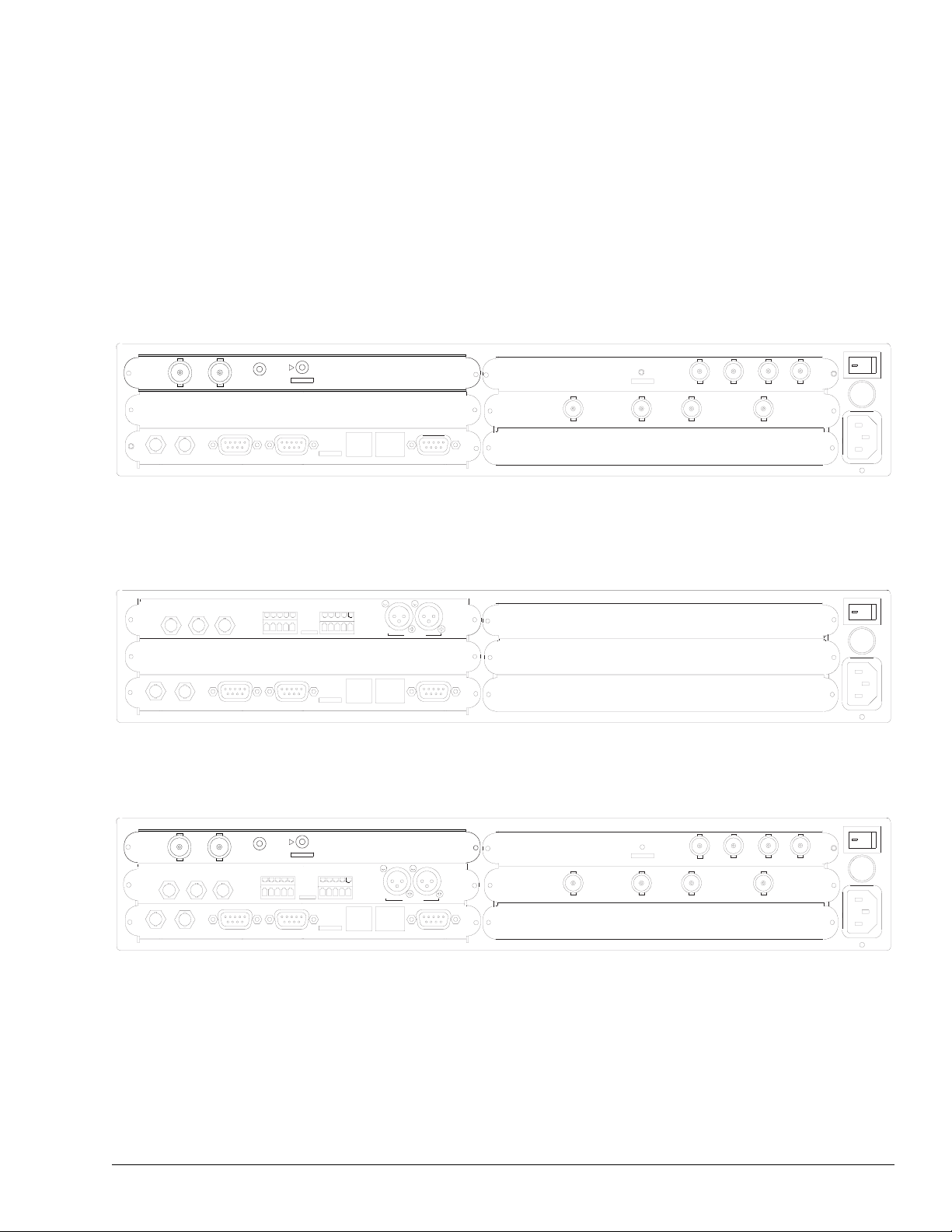
Rear Panel
Connections
The rear panel consists of option modules that have been selected and installed
according to the needs of your organization. Available options modules include:
■ TMAC-6125 — master controller module for both SD and HD applications
■ TDEC-6161 — decoder module for HD applications
■ TDEC-6100 — decoder module for SD applications
■ TAUD-6100 — audio module providing 4 additional channels of audio
■ TDEM-6110 — demodulator module for providing four L-band inputs
The location of the connection ports on the rear panel may vary depending on
configuration of the option modules installed in your unit.
SDI OUT 1 SDI OUT 2
ASI
IN
IN
TDEC 6100
OUT
COMPOSITE
ASI
OUT
GENLOCK
USER DATA B
D1
USER DATA B
PUSH
HERE
USER DATA A
ANALOG AUDIO A
-
+
USER DATA A
FAULT RLY
ETHERNET
REMOTE
TDEC 6161
TMAC
6125
TDEM 6110
AUDIO A AUDIO B
LNB1
LNB2
AUDIO C AUDIO D
PUSH
HERE
AES/EBU TAUD 6100
LNB4LNB3
TDR6 HD Configuration with Optional Demodulator and Audio Modules
Installed
ANALOG AUDIO B
LEFTLEFT
RIGHTRIGHT
A
B
ETHERNET
AES/EBU
REMOTE
TMAC
6125
-
+
+
+
FAULT RLY
-
-
Basic TDR6 SD Configuration with No Option Modules Installed
SDI OUT 1 SDI OUT 2
TDEC 6100
GENLOCK
COMPOSITE
ASI
IN
OUT
Installing the TDR6
D1
USER DATA B
PUSH
HERE
ANALOG AUDIO A
-
-
+
USER DATA A
TDEC 6161
ANALOG AUDIO B
LEFTLEFT
RIGHTRIGHT
A
B
ETHERNET
AES/EBU
REMOTE
TMAC
6125
-
-
+
+
+
FAULT RLY
TDEM 6110
AUDIO A AUDIO B
LNB1
LNB2
AUDIO C AUDIO D
PUSH
HERE
AES/EBU TAUD 6100
TDR6 Fully Configured for Both HD and SD Operations; All Option Modules are
Installed
01-0870-401B 01/03 7
LNB4LNB3
Page 18

TMAC-6125 The TMAC-6125 is the master controller module.
ASI
IN OUT
TMAC-6125
PUSH
HERE
FAULT RLYUSER DATA B USER DATA A REMOTE
ETHERNET
TMAC-6125 Ports
The TMAC-6125 provides the following ports:
■ ASI IN – accepts the incoming ASI transport stream, with data rates up to
104 Mbps, on a female BNC connector, 75Ωimpedance
■ ASI OUT – outputs a DVB/ASI compliant transport stream as a loop through
of the input signal on a female BNC connector, 75Ω impedance. The output
follows the input selected, i.e., ASI or RF.
The ASI Out port provides a pass through relay; if power is lost, the input is
directly connected to the output.
■ USER DATA A and B – identical data ports that are independently
configurable for either RS-422 synchronous/asynchronous communications
up to 4.096 Mbps or RS-232 asynchronous communications up to 38.4 kbps
Both User Data ports are female, DB-9 connectors.
■ FAULT RLY (relay) – female RJ-11 connector that provides three
connections to create a form-C status relay
The fault relay indicates a non-normal, or fault, condition when power is
removed through a power failure, a power switch turned off, or an unplugged
unit. The fault relay can also report user-programmable faults.
A fault condition is indicated by contact closure between pins one and three,
and an open contact between pins one and six. Fault Relay pin assignments
are provided in the port pinout appendix.
■ ETHERNET – female RJ-11 connector that provides remote control of the
TRD6 over a network
■ REMOTE – female DB-9 connector that provides an RS-232 remote control
interface to the TRD6
Remote control port pin assignments are provided in the port pinout appendix.
8 01-0870-401B 01/03
Connecting to a Remote Unit
The TMAC-6125 enables you to connect a remote unit to the TDR6 using the
Remote port. A remote unit may be any device capable of asynchronous
communications at RS-232 electrical levels including:
■ Personal computer with an asynchronous communications software
application installed
■ ASCII computer terminal
To install a remote unit:
1. Connect a cable between the remote unit and the TDR6 remote control port.
2. Configure the communications software parameters of the remote unit to
match the DVB default settings of the TDR6 remote control port.
Installing the TDR6
Page 19

3. Press the enter key on the remote unit several times until a prompt appears on
the display of the remote unit. Typically the prompt is the > character.
Once the prompt appears, successful communications have been established
between the TDR6 and the remote unit.
If communications cannot be established between the TDR6 and the remote
unit, refer to the chapter on troubleshooting.
4. Reconfigure the remote control port settings as required for your site.
Connecting to a Network
You can connect the TDR6 to a LAN using the TMAC-6125 Ethernet port, which
enables you to monitor and control the TDR6 through a remote unit not directly
connected to the TDR6.
To connect a TDR6 to the Ethernet port:
When connecting the TDR6 to the Ethernet port, contact your Information System department to
coordinate installation and setup.
NOTE
1. Connect a Category 5 cable with RJ45 connectors (standard ethernet cable)
between the TDR6 Ethernet port and a LAN hub.
2. Assign the device a unique IP address, if necessary.
The TDR6 default IP address is 192.200.9.201. Contact your Information
Systems department for a valid IP address.
To change the IP address using the front panel:
a. Select
Control>Network>IP Addr.
b. Using the keypad, enter the IP address in the format xxx:xxx:xxx:xxx
where xxx is a decimal number between 0 and 999.
c. Press the Enter button
To change the IP address using a remote unit, enter the command
ETHERNET IP ADDRESS XXX.XXX.XXX.XXX
where XXX is a decimal
number between 0 and 999.
3. Assign additional network information, if necessary.
Depending on the configuration of the LAN, you may need to enter additional
parameters including:
❒ Ethernet IP address mask (IP subnet mask)
❒ Ethernet IP gateway
For additional information, refer to the MC commands in the chapter on using
a remote unit.
4. From a personal computer connected to the LAN, try to ping the TDR6. At
the command prompt of the personal computer, type
ping <TDR6 IP address> where <TDR6 IP address> is the
previously assigned address.
If a reply is received, the TDR6 is correctly configured.
For information on establishing remote communications, refer to the chapter on
using a remote unit.
MC
Installing the TDR6
01-0870-401B 01/03 9
Page 20
TDEC-6161 The TDEC-6161 supports decoding of HDTV signals in either 1080i or 720p
format. Video is output at 1.5 Gbps using the SDI interface.
The TDEC-6161 has two SDI ports, labeled SDI OUT 1 and SDI OUT 2.
TDEC-6161
SDI OUT 1 SDI OUT 2
PUSH
HERE
TDEC-6161 Ports
These two SDI ports provide identical serial digital bitstream outputs, using a 75Ω
low-loss SDI cable. Both SDI OUT ports are BNC, 75Ω female connectors.
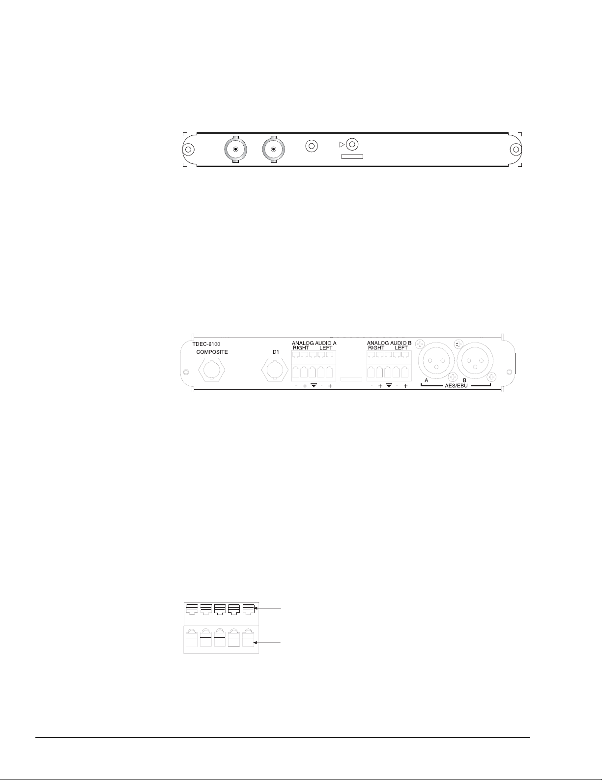
TDEC-6100 The TDEC-6100 SDTV video and audio decoder module processes MPEG-2
4:2:2 Profile @ Main Level and Main Profile @ Main Level. Video may be output
as composite analog NTSC or PAL or serial digital.
The module processes audio MPEG-2 Layer I or Layer II. Audio may be output as
analog or AES/EBU digital stereo.
TDEC-6100 Ports
The TDEC-6100 ports are as follows:
■ COMPOSITE—outputs composite analog video on a female BNC 75Ω
connector
■ D1—outputs digital video on a female BNC 75 Ω connector
■ ANALOG AUDIO A and B—output balanced analog audio on terminal block
30 Ω connectors which are factory selectable to 600 Ω
■ AES/EBU A and B—output balanced digital audio on male XLR 110 Ω
connectors
Cabling the Analog Audio Connectors
The terminal block connectors consist of a row of detents on the top of the
connector and a row of clamps on the bottom, as shown in the following graphic.
Detents
Clamps
10 01-0870-401B 01/03
Installing the TDR6
Page 21
To cable the Analog Audio terminal block connectors:
1. Press the detent using a screw driver with a maximum width of .15 inch to
open the clamp below it.
2. Insert audio cable wire into the clamp.
3. Release the detent. The clamp will close tightly on the inserted wire.
Opening the clamp requires firm pressure. The required pressure may temporarily deflect the rear
panel, but will not damage the unit.
NOTE
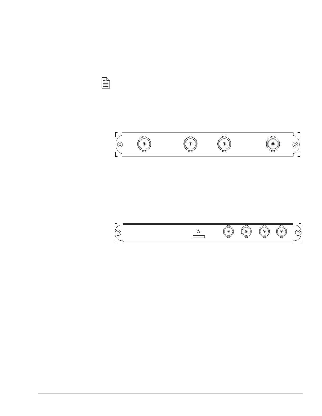
TAUD-6100 The TAUD-6100 four-channel audio module process four MPEG-2 audio streams
and provides AC3 audio passthrough.
AUDIO A AUDIO B
PUSH
HERE
AES/EBU TAUD-6100
AUDIO C AUDIO D
TAUD-6100 Ports
These four audio ports output unbalanced digital AES/EBU audio on female BNC
75 Ω connectors.
TDEM-6110 The TDEM-6110 QPSK demodulator module enables the TDR6 to perform as an
SDTV or HDTV IRD with four L-band inputs.
TDEM-6110
LNB A
LNB B
TDEM-6110 Ports
The LNB 1 through LNB 4 connectors are F-Type, 75 Ω female connectors that
accept RF from 950 to 2150 MHz, at power levels between -65 dBm and
-25 dBm.
LNB DLNB C
Installing the TDR6
Cabling the TDEM-6110
LNB ports A through D are used to connect the TDR6 to up to four satellite
antenna LNBs. Although each of the four RF inputs can be independently
configured, only one port may be active at a time.
The IFL cable loss should not exceed 25 dBm to ensure reliable IRD operation
over a broad range of satellite operating parameters and varying weather
conditions.
LNB Power
In the default configuration, the TDR6 does not supply DC power to the LNB.
However, the TDEM6110 can be configured so that the active LNB IN port
outputs LNB DC power at <500 mA DC at either 13V or 18V.
01-0870-401B 01/03 11
Page 22

12 01-0870-401B 01/03
Installing the TDR6
Page 23
Front Panel
This chapter describes the following TDR6 front panel information:
■ Components
■ Navigating through menus
■ Description of menus, parameters, and options
3
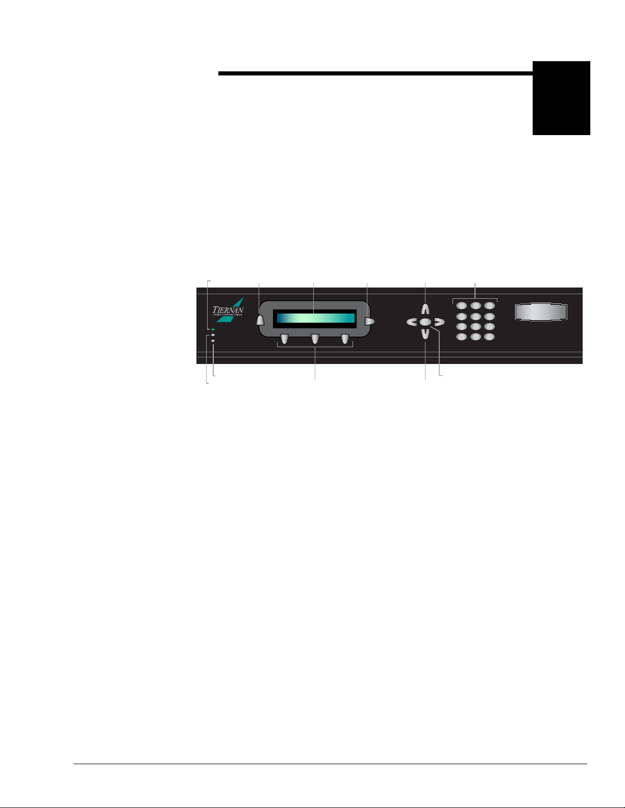
Front Panel
Components
The front panel enables you to easily and efficiently configure and monitor the
TDR6.
Power LED
POWER
FAULT
STATUS
Status LED
Fault LED
Previous
Button
PREV
LCD
Display
Selection
Buttons
Next
Button
Enter
Button
Numeric
Keypad
123
456
789
0-
.
TDR6
DTV Decoder
Up Button
NEXT
ENTER
Down
Button
TDR6 Front Panel
■ LED indicators – alert you to power, fault, and status conditions
■ Previous button – used to scroll up to a previous menu level or leave a
parameter without changing it’s option
■ LCD – displays menus, parameters, information, and messages
■ Selection buttons – used to select the item displayed directly above the button
■ Next button – used to scroll within the current menu level, or to scroll forward
through a list of parameters
■ Up and Down buttons – used to scroll through parameter options and increase
and decrease parameter values
■ Left and Right buttons – only available when entering alphabetic characters
for BISS mode commands
■ Enter button – used to issue a command or set a parameter
■ Numeric keypad – used to enter numeric values; also used to enter alphabetic
characters for BISS mode commands
Front Panel
01-0870-401B 01/03 13
Page 24

TDR6 Menu The following menu structure shows the standard TDR6 menus. Your front panel
menus may vary depending upon the option modules installed in the unit.
TDR6 DTV Receiver/Decoder Menu Structure
Main Menu Submenus
Config
Details
Default
User
1
Input
Service
Video Slot_1 to Slot_5 Std Vid
Audio Audio_A to Audio_F PID Source
Data Data_A and Data_B
Config
Status
Slot_1 to Slot_5
Format VBI Format VBI Fmt CntrlVBI
Select
Demod
Filter PCR Filter
RF
ASI
2
3
4
RF_A to RF_D
HD Vid
Functions/Parameters
Restore
Restore Save
Input
Modulation
Sym Rate LNB Power
Acq Range
Eb/No Offset Demod
Transport
Rx Level
Signal
Number Auto Select
PID
Tiernan Closed Cap Delay
PID DelayFrame Rate
Preferred Delay
Data Rate
PID
Config Mode
Stop Bits
RF Freq LO Freq Code Rate
Data Rate
Rate
Peak Jitter
Transport Rate Peak Jitter
Mode
For mat
Source Interface
PAL Submode
Channel Mode
Baud Data Bits Parity
Decoder
Raw BER BER
Sample Rate
Handshake
Setup 7.5 IRE
Chroma
Chroma
Volume
PGCA Status
BISS Status 1 Key E Key E ID BISS Mode
Faults Current
History
Clear
Control FP_Lock
EIA-232
Network
Clock
Reset
Version Firmware
1. Options on the Input menu correspond to the input type selected.
2. Options on the Video menu correspond to the type of video: HD or SD.
3. Options on the Audio menu correspond to the type of audio: HD or SD.
4. Options on the Data menu correspond to the type of data: synchronous or asynchronous.
14 01-0870-401B 01/03
<list of current faults>
<list of previous faults>
"Press ENTER to Clear"
State Password
Baud Data Bits Parity Stop Bits
Address
Date Time
"Press ENTER to Reset"
Soft Flow Hard Flow
Mask
Gateway
MAC
Front Panel
Page 25

Navigating Through
the Menus
LCD Display LCD Symbols
The front panel LCD display and buttons were designed to help you navigate
through the TDR6 menu structure quickly and efficiently.
There are four important symbols that appear on the LCD:
■ Arrow (→ ) ■ Asterisk (*)
■ Equal sign (=) ■ Colon (:)
Arrow As you are navigating through the TDR6 menus, an arrow will often
display on the LCD. Depending upon where you are in the menu structure, this
arrow denotes the following information:
■ At a menu level the arrow indicates that there are additional items available at
that current menu level
■ In a list of parameters the arrow indicates that there are additional items
available in that parameter list
Asterisk While the TDR6 is executing a command or setting a parameter, an
asterisk (*) appears on the LCD, indicating that the TDR6 is processing
information. When the asterisk disappears, the process is complete.
Equal Sign Most parameters, though not all, can be modified in order to
configure the TDR6. Configurable parameters are followed by an equal sign,
denoting that the parameter option can be modified.
Colon There are some parameters that are automatically set for your system or
that are query-only parameters. These type of parameters are followed by a colon.
When a parameter is followed by a colon, that parameter can be viewed but not
changed.
LCD Text Formats
All menus, parameter options, and system information are displayed on the front
panel LCD.
Menus All menus are displayed in the following format.
DTV Receiver/Decoder
Config Details Faults
■ The first line identifies the current menu level, in this example, the main menu
→
labelled DTV Receiver/Decoder.
■ The second line identifies the available menu options.
■ The arrow, when displayed, signifies that there are additional menu options
available at that level.
Front Panel
01-0870-401B 01/03 15
Page 26

Parameter Options All parameter options are displayed in the following format.
Data A Menu
Baud= 38400 bps
■ The first line identifies the current menu level, in this example, the Data A
→
menu.
■ The second line displays the parameter, Baud, and its current setting of
38400 bps.
■ The equal sign (=) denotes that this parameter can be modified. If this
parameter was followed by a colon (:) the parameter would be view-only.
■ The arrow indicates that additional User Data A parameters can be scrolled to
by pressing the Next button.
Information Information, such as current faults, faults in the history log, and
system messages are displayed as ASCII text strings as shown in the following
example.
Current Faults
DC Input Signal Loss
■ The first line identifies the type of information displayed, in this example,
current faults.
■ The second line lists one line of information, in this example, the most recent
current fault.
■ There is no arrow displayed, signifying that there are no additional current
faults.
Front Panel
Navigation Buttons
The following front panel buttons are used to move through menus in order to
issue commands and view status and fault information:
■ Next ■ Up and Down
■ Previous ■ Enter
■ Selection ■ Numeric keypad
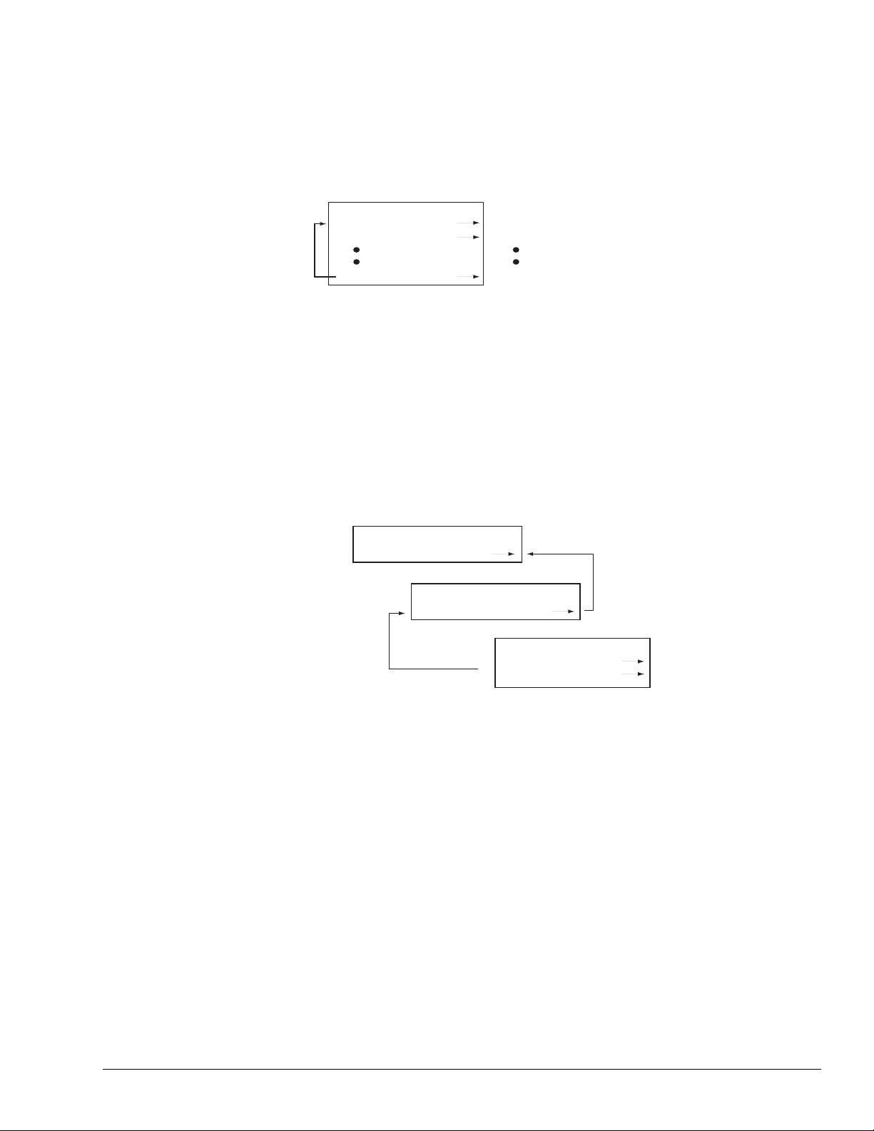
Next Button The Next button can be used when a right arrow is displayed on the
LCD. The Next button moves you through the menu structure in the following
manner:
■ At a menu level, the Next button scrolls forward through all available menu
items at that current level. When the last menu item is displayed, the TDR6
begins scrolling through the list again. The following graphic illustrates how
the Next button functions at a menu level.
Press Next;
System Returns to
Beginning of Menu
Next Group of Menu Items
DTV Receiver/Decoder Menu
Config Details Faults
Press Next
System Displays
MPEG2 Receiver/Decoder Menu
Control Version
16 01-0870-401B 01/03
Front Panel
Page 27
■ In a parameter list, the Next button scrolls forward, one parameter at a time,
through all parameters. When the last parameter is reached, the TDR6 scrolls
through the list again.
LCD Display
Demodulator Menu
RF Freq 11210 Mhz
LO Freq 10000 Mhz
Press Next; Next Parameter Displays
Press Next; Next Parameter Displays
Modulation QPSK
Press Next; System Returns to
First Parameter
Parameter lists can only be scrolled through in a forward motion. If you
accidentally scroll past the required parameter, you cannot backup using the
Previous button; the Previous button will move you out of the parameter list up to
the previous menu level. Instead, continue to press the Next button until the
required parameter displays again.
Previous Button The Previous button moves you through the menu structure in
the following manner:
■ At a menu level, the Previous button moves you up one menu level.
■ In a parameter list, the Previous button moves you up to the previous menu
level.
DTV Receiver/Decoder Menu
Config Details Faults
Press Previous From any Menu;
Control Menu
Clock Reset
Clock Menu
Date 05/26/2003
{
Press Previous From any Parameter;
System Returns to the Previous Menu Level
Time 14:23:46
System Returns to the
Previous Menu Level
Front Panel
Select Buttons The three Selection buttons are used to select the menu item or
parameter option displayed on the LCD. To select the displayed item, press the
Select button located directly below it. The Select button performs the following
tasks:
■ At a menu level, the Select button moves you to the selected submenu
■ In a parameter list, the Select button causes the parameter and it option to
flash, indicating that you can modify that parameter’s option.
Once the parameter is flashing, you can continue to press the select button to
scroll through the list of available options. However, for those options that
require a numeric value, the value must be entered using the numeric keypad
— the selection buttons will not increment a numeric value.
Up and Down Buttons The Up and Down buttons are not labeled, but are
located above and below the Enter button, respectively. Once a parameter is
selected, use the Up and Down buttons to scroll through its available options. If
the option is a numeric value, the Up and Down buttons can be used to increase
and decrease the numeric value.
01-0870-401B 01/03 17
Page 28

Enter Button The Enter button is used to issue a command, such as the clear
history log command, or to set a parameter option, such as a video delay. The
Enter button performs the following tasks:
■ When the required command is displayed, the Enter button executes the
command.
■ When a parameter value is correctly displayed, the Enter button configures
the system with the new parameter value. The new values are then stored in
nonvolatile memory.
Numeric Keypad The keypad is used to enter a numeric parameter value. When
entering numeric values with the keypad, the Up and Down buttons can be used to
correct errors:
■ The Up button changes the value to 0; the correct value can then be entered
■ The Down button deletes the numbers, from right to left; the correct value can
then be entered
Alpha-numeric
Entries
The alpha-numeric keypad is enabled when entering BISS Key and BISS ID
command parameters. To correct any alpha-numeric characters, use the left arrow
to delete the characters. To copy and insert the last character entered, press the
right arrow key.
Alphabetic Entries — when entering values in an alpha-numeric field, the
following alphabetic and numeric characters are displayed when a key is pressed:
Key Character Displayed
1 . , ? ! - 1
2A B C 2
3D E F 3
4 G H I 4
5J K L 5
6M N O 6
7P Q R S 7
8T U V 8
9W X Y Z 9
0
space
0 ‘ +
The first press of a number key displays the first character in the set; sequential
presses of the same key advance through the character set, in a circular fashion.
The cursor is advanced by either pressing another number key, or by pressing the
right arrow key. For example to enter the word
ALL which has two characters in
the same characters set, the following keys would be pressed:
■ 2 selects A
■ 555 selects L
■ → advances the cursor so the next letter can be selected
■ 555 selects L
18 01-0870-401B 01/03
Front Panel
Page 29

A space can be entered by either a single press of the “0” key. For example, to
enter the words LA Default the following keys would be pressed:
■ 555 selects L
■ 2selects A
■ 0 selects space
■ 3selects D
■ → advances the cursor so the next letter can be selected
■ 33 selects E
■ → advances the cursor so the next letter can be selected
■ 333 selects F
■ 2selects A
■ 88 selects U
■ 555 selects L
■ 8selects T
■ Enter to issue the command
Issuing Commands To issue a command from the front panel, perform the following steps:
1. Navigate to the required command or parameter using the Next and Selection
buttons.
2. Select the parameter to be modified. The parameter and its option will begin
to flash.
3. Change the parameter option as required:
❒ If the available options appear in a list, scroll through the list using the
Up, Down, or Select buttons.
❒ If the option requires a numeric value to be entered, enter the value using
either the Up and Down buttons to increment the value or using the
numeric keypad to type in the value.
4. Issue the command by pressing the Enter key. An asterisk will briefly display
and then disappear when the system is finished processing the request. The
parameter, with its updated value, is then displayed and does not flash.
❒ If the Enter button is not pressed, the parameter is not changed.
❒ While the TDR6 is reconfiguring the parameter to the new value, the front
panel is temporarily disabled.
The TDR6 configuration files are stored in non-volatile memory. When the TDR6
configuration is changed using the front panel, the changes are automatically
stored in non-volatile memory. The TDR6 automatically restores to the saved
NOTE
configuration whenever the unit is reset or powered up.
Correcting Mistakes Selecting Options from a List If you are selecting a parameter from a list, and
have not pressed the Enter button, use the Up or Down buttons to scroll to the
correct option.
Using the Keypad If you are entering a value with the keypad, and you have
not pressed the Enter button, you can either:
■ Press the Up button to change the value to 0, then enter the correct value
■ Press the Down button to delete the numbers (from right to left), then enter the
correct value
Front Panel
01-0870-401B 01/03 19
Page 30

Leaving a Parameter If you have not pressed the Enter button, you can leave a
parameter without modifying it by pressing either the:
■ Previous button which returns you to the previous menu level
■ Next button which advances you to the next parameter in the list
In either situation, the TDR6 will ignore any values entered and return the
parameter to its original setting.
After Pressing the Enter Button If you accidentally issue an incorrect parameter
value to the TDR6, you can correct the error by:
1. Selecting the parameter again using the Selection buttons. The parameter will
begin to flash.
2. Change the parameter option to the correct value.
3. Issue the parameter again by pressing the Enter button
Example
The following example describes how to move through menus and select options.
In this example, the video mode will be set to NTSC. This example applies to the
video card located in slot 2, and is for standard definition video.
1. From the DTV Receiver/Decoder main menu, select Details.
DTV Receiver/Decoder
Config Details Faults
→
2. From the Low Level Setup menu, select Video.
Low Level Setup
Input Service Video
→
3. From the Video Decoder menu, select Slot 2.
Video Decoder Menu
Slot 2
4. From the Slot 2 Video menu, select standard definition.
Slot 2 Video Menu
Std_Vid
5. The Standard Definition Video Decoder menu displays, showing the first
video parameter and it’s current setting. Press Next to scroll to the next
parameter.
Std Video Decoder
PID = 33
→
20 01-0870-401B 01/03
Front Panel
Page 31

6. The Mode parameter and its current setting display.
Std Video Decoder
Mode = PAL
→
7. Press the Select button under the PAL option. The parameter begins to flash.
8. Scroll to the NTSC parameter using the Up, Down, or Select button.
Std Video Decoder
Mode = NTSC
→
9. Press the Enter button. When the parameter stops flashing, the TDR6 has set
the new video mode.
Menu Descriptions A complete description of all TDR6 menus is provided in this section. The menus
actually available depend on the specific option modules installed in your unit.
Command Description Parameters / Response Values
Configuration Menu: consists of two submenus, Default and User, which enable you to quickly and easily re-initialize the unit using
predefined factory default configuration settings or your own user-defined configuration settings.
Configuration>Default: predefined configuration sets allow common operating modes to be stored in the unit at the factory, or at a
customer depot, and then easily recalled and implemented on-location in field operations. These configuration sets are not altered
by reset, power cycling, or factory DVB default setting of the decoder.
Restore Initializes the TDR6 using the pre-defined factory configuration
Configuration>User: used to save and restore site-specific configuration parameters in non-volatile memory and then recall these
stored parameters in order to re-initialize the TDR6 when your site requirements change.
Restore Initializes the TDR6 using the selected user-stored, site-specific
Save Saves the current site-specific configuration in non-volatile
Details Menu: enables you to configure the input, services, video, audio, data, and conditional access for the TDR6
Details>Input>Config>Select: used to select the type of input for the TDR6
Input Selects the input source for the TDR6 ■ ASI: selects the external ASI input source
Details>Input>Confi g>Dem od>RF: allows you to configure or query the dem odulator parameters; the RF menu appears only if an
RF input has been selected using t he Deta ils>Input>Config>Select menu.
Each of the four RF inputs, A through D, can be independently configured, although only one may be active at one time.
Modulation Sets the modulation type. QPSK, 8PSK, 16QAM
RF Freq Sets the RF frequency for the QPSK demodulator
parameters
parameters
(flash) memory under the selected option
Note: The IF frequency is the absolute value of the difference
between the RF frequency and the LO frequency. The
demodulator has a valid IF frequency in the range of 2150 MHz
and 950 MHz. Entering values for RF or LO that equal an out of
range IF frequency value will result in an IF value that is either
the maximum or the minimum IF frequency.
■ Default1
■ Default2
■ Default3
■ DVB
User1, User2, User3
User1, User2, User3
■ RF_A, RF_B, RF_C, RF_D: selects the TDR6
internal demodulator as input source; selects
the option that corresponds to the LNB port
you want to be the active port
950 to 2150MHz above or below your local
oscillator frequency
Front Panel
01-0870-401B 01/03 21
Page 32

Command Description Parameters / Response Values
LO Freq Sets the frequency to match your LNB downconverter local
oscillator frequency.
Note: The IF frequency is the absolute value of the difference
between the RF frequency and the LO frequency. The
demodulator has a valid IF frequency in the range of 2150 MHz
and 950 MHz. Entering values for RF or LO that equal an out of
range IF frequency value will result in an IF value that is either
the maximum or the minimum IF frequency.
Code Rate Sets the Viterbi code rate ■ QPSK: 1/2, 2/3, 3/4, 5/6, or 7/8
Sym Rate Sets the demodulator to the frequency of the incoming RF signal.
Note: If an out-of-range value is entered the TDR6 will not
accept the new value and will revert to the previous value
entered.
Since the data rate is proportional to the symbol rate, entering a
data rate value might fail if the corresponding symbol rate is out
of range.
Converting a symbol rate to data rate and vice versa may be
subject to a small rounding error. The error is less than
0.00001%. It is advisable to use the symbol rate representation
when entering parameters if a conversion error cannot be
tolerated.
In cases where the demodulator is not locking on the carrier, it is
necessary to add an offset to the symbol rate. This compensates
for the symbol rate drift. The range of the offset is between
0.0002% and 0.0006%; in general a value of 0.0004% proves
successful to lock on the carrier in these cases.
Data Rate Sets the data rate of the transport data stream 2 to 48Mbps
LNB Power Sets the voltage of the LNB Off, 13 V, 18 V
Acq Range Defines the size of the frequency range over which the
demodulator will search for the carrier.
Details>Input>Config>Filter: allows you set the PCR filter
PCR Filter Sets the PCR (program clock reference) filter for normal
operations or operations over an ATM network.
Details>Input>Status>RF: allows you to query the receive signal Eb/N0 level, the carrier offset, and the current lock status of the
demodulator, decoder, and transport stream; this menu only applies to the currently active RF input.
Eb/N
0
Query-only; displays the Eb/N0 of the RF receive signal
Note: E
Details>Input>Config>Select>Input is set to RF.
is only available when
b/N0
Offset Query-only; displays the RF offset.
The Offset measures the difference, in MHz, between the actual
carrier frequency received by the TDR6 and the carrier
frequency the TDR6 calculates by subtracting the LO parameter
from the RF parameter. For optimum performance, the Offset
parameter should be as close to zero as possible.
For more information regarding the offset, refer to the chapters
on configuration and troubleshooting. Also refer to the appendix
on the QPSK demodulator.
Note: Offset is only available when
Details>Input>Config>Select>Input is set to RF.
Demod Query-only; displays the lock status of the demodulator
Note: Demod is only available when
Details>Input>Config>Select>Input is set to RF.
Decoder Query-only; displays the lock status of the decoder
Note: Decoder is only available when
Details>Input>Config>Select>Input is set to RF.
Transport Query-only; displays the lock status of the transport stream Locked, Unlocked
Rate Query-only; displays the output rate for the QPSK demodulator value in bps
2000 to 15000MHz
■ 8PS K: 2/3, 5/6, 8/9
■ 16QAM: 3/4, 7/8
37500000 sps and 1000000 Sps
To convert symbol rate to data rate, use the
following equation:
Symbol rate x 2 x (188/204) x FEC code rate
To convert data rate to symbol rate, use the
following equation:
Data rate x 1/2 x (204/188) x 1/FEC code rate
0 to 7500000 Hz
■ Normal: set for normal operations
■ AT M : set for operations over an ATM network
Displays the value in dB; value is ± 2 dB
Eb/No values above 16 dB are not significant.
Frequency in MHz
Locked, Unlocked
Locked, Unlocked
22 01-0870-401B 01/03
Front Panel
Page 33

Command Description Parameters / Response Values
Raw BER Query-only; displays the raw bit error rate; this rate is the error
rate of the signal as it is received from the satellite, before error
correction is applied.
BER Query-only; displays the bit error rate; this value represents the
number of errors detected in the signal after error correction is
applied. This rate should be a zero for correct performance.
Rx Level Query-only; displays the power level of the input signal. value in .dBm
Peak Jitter Query-only; displays the difference, or jitter, between the STC
and PCR clocks.
Details>Input>Status>ASI: allows you to query the presence of the ASI signal, as well as other transport stream parameters
Signal Query-only; displays if the ASI signal is present or not
Note: Signal is only available when
Details>Input>Config>Select>Input is set to ASI.
Transport Query-only; displays the lock status of the transport stream Locked, Unlocked
Rate Query-only; displays the output rate for the QPSK demodulator value in bps
Peak Jitter Query-only; displays the difference, or jitter, between the STC
and PCR clocks.
Details>Service: consists of two submenus, Number and Auto Select, which enable you to query and select the services available in
the transport stream.
Once you have selected a service, the Video Decoder, Audio Decoder, and User Data menus display the PIDs available for the
selected service.
Number Selects a service from those available in the transport stream.
Once a service is selected, the TDR6 processes that service
until:
■ Another service is selected
or
■ The selected service is no longer available in the transport
stream
Auto Select Determines which service, including audio and data services,
that the TDR6 will select when any of the following events occur:
■ The TDR6 power is turned off and then restored, or the unit is
reset
■ The TDR6 loses and then re-establishes lock on the transport
stream
Note
: Since the typical SCPC transmission consists of a single
service that includes of a single video/audio pair, the Auto Select
feature was added to simplify the configuration process for
typical SCPC users. When the Auto Select feature is enabled, or
set to On, the decoder automatically selects the service with the
lowest service number first, then selects the video component
with the lowest PID, and finally selects the audio components
with the lowest PIDS for audio A/B.
With Auto Select set to Off, the decoder can be configured to
process a particular service, and within that service, to process
selected video and audio services.
—
—
value in ns
Present, Absent
value in ns
Displays a list of available services.
■ Eac h available service in the transport stream
consists of a program number, a service
name, and a service provider.
■ If the transport stream does not contain
service names and providers, only the
program numbers are displayed.
■ If the transport stream input is not connected,
or if it lacks PSI information, the LCD displays
the message:
■ On – when Auto Select is set to On, the TDR6
automatically selects the first available service
in the transport stream.
Note
: If you change the Auto Select function to
On after you have selected a service, the
No services available
.
TDR6 will continue to process the service you
selected until one of the events occurs, then
the TDR6 selects the first available service in
the transport stream.
■ Off – when Auto Select function is set to Off,
the TDR6 searches the transport stream for
the last service you manually selected.
If the service is found in the transport stream,
the TDR6 selects the service, and the LCD
displays the program number, service name,
and service provider.
If the service is not found in the transport
stream, the LCD displays
Available
and no video, audio, or user data will be
, the TDR6 does not select a service,
Service Not
output.
Front Panel
01-0870-401B 01/03 23
Page 34

Command Description Parameters / Response Values
Details>Video Menu: used to configure the TDR6 video.
To configure the video, you must first select the video slot that corresponds to the video option card you want to configure.
Once you have select the slot, you can set the video parameters for your site requirements.
Note
: The options on the slot menu depend on the specific configuration of the TDR6.
Details>Video>Standard Video: enables you to set the parameters for standard video. This menu only appears if the TDR6 has a
standard video option mo dule installed.
The TDR6 auto-sensing video decoder automatically changes the video parameters to match the incoming signal
PID Selects or displays the video PIDs available in the current
service
Mode Sets the video format NTSC, PAL, AUTO
PAL Submode Sets the video PAL Submode when Mode = PAL B, D, G, H, I
Setup 7.5 IRE Selects the Setup 7.5 IRE mode On, Off, Auto
Tiernan Closed Cap Providing that line 21 closed captioning is available in the
selected service, this command determines whether line 21 will
be included in the video output stream.
Note: Closed Captioning is only available when video>standard
definition>mode is set to NTSC.
Delay Sets the delay between the time the video data is received and
the time the video data is sent to the video output port.
Delay is provided primarily for interoperability with other
manufacturers’ equipment. It is not normally necessary to enter a
non-zero delay value.
Chroma Query-only; displays the video chroma format for the video input
transport stream.
Details>Video>High Definition>Video: allo ws yo u to configure and query video para mete r s us ing the PID, format, delay, and fr a m e
rate options. This menu only a ppe a r s if the TDR6 has a high-definition vi de o c a r d mod ule installed.
The TDR6 auto-sensing video decoder automatically changes the video parameters, with the exception of the delay parameter, to
match those of the input signal. The video delay must be set manually.
PID Selects or displays the video PIDs available in the current
service.
Format Query-only; displays the video format 1080I, 720P
Frame Rate Query-only; displays the video frame rate, which is auto-detected
Delay Sets the delay between the time the video data is received and
by the TDR6
the time the video data is sent to the video output port.
Delay is provided primarily for interoperability with other
manufacturers’ equipment. It is not normally necessary to enter a
non-zero delay value.
Chroma Query-only; displays the video chroma format for the video input
transport stream.
Video PIDs available in the selected service. If no
video PIDs are present, the system displays
no video present.
To disable video output, select the video off
option.
■ On – line 21 data will be included
When Closed Captioning set to On, the Vert
Offset is automatically set to -1.
■ Off – line 21 will not be included
Default: Off
-1000 to +1000
n/a, 4_2_0, 4_2_2, 4_4_4
Video PIDs available in the selected service. If no
video PIDs are present, the system displays
no video present.
To disable video output, select the video off
option.
■ 29.97 fps and 30 fps for 1080I formats
■ 59.9 4 fps and 60 fps for 720P formats
-1000 to +1000
n/a, 4_2_0, 4_2_2, 4_4_4
24 01-0870-401B 01/03
Front Panel
Page 35

Command Description Parameters / Response Values
Details>Audio: used to configure the TDR6 audio.
To configure the audio, you m us t first select the audio slot a nd por t that corresponds to the aud io option card you want to
configure.
The Audio menu contains submenus for each audio port on the selected option card based on the following:
■ If only a TDEC-6100 option module is installed, audio ports A and B display
■ If only a TAUD-6100 option module is installed, audio ports A to D display.
■ If both option modules are installed, audio ports A, B, C, and D correspond to the audio ports located on the TAUD6100 board,
while audio ports E and F correspond to the audio ports located on the TDEC-6100 option module.
Each menu for the selected audio port has identical parameters and options which allow you to monitor and control the individual
audio ports. However, options vary depending on whether the audio is SD or HD.
Once you have selected the port, you can set the audio parameters.
Note
: The options on the slot menu depend on the specific configuration of the TDR6.
Note
: The TDR6 auto-sensing audio decoder automatically changes the audio parameters, with the exception of the delay
parameter, to match thos e of the input signal. The audio dela y mu s t be s et m anually.
PID Selects or displays the audio PIDs and their associated
language codes for the selected service.
Source Query-only; displays the input audio source for the currently
selected PID
Channel Mode Sets the audio format of the output audio channel
Note: Channel Mode is only available when the audio source is
MPEG-2.
Volume Sets audio volume for analog audio output.
The TDR6 cannot increase or amplify the incoming audio level. If
the volume is set to 18 dBu, the output volume equals that of the
input signal level.
If you set the audio volume to a value less than 18 dBu, the
TDR6 attenuates the input signal level.
Note: Volume is only available when the audio input is analog.
Preferred Selects the designated language from the languages available in
Delay Sets the compressed audio bit stream buffer delay, which
the selected service
controls the amount of time delay between the audio and video
Sample Rate Query-only; displays the audio sample rate. Only available in
MPEG audio mode.
Data Rate Query-only; displays the audio data rate. 0 to 640
Details>Data: used to set the user data options; options are different for asynchronous or synchronous data.
PID Selects the data channel Available user data PIDs. If no data PIDs are
Source Query-only; displays the encoder data channel parameter
settings
Interface Set s the hardware interface RS-232, RS-422
Audio PIDs available in the selected service. If no
audio PIDs are present, the system displays
no audio present.
To disable audio output, select the audio off
option.
MPEG-2, Uncompressed, ATSC
■ Left: selects the audio stream from the left
channel and supplies it to both the audio left
and audio right outputs
■ Right: selects the audio stream from the right
channel and supplies that stream to both the
audio right and audio left outputs
■ Stereo: Supplies both mono streams to the
audio left and right outputs exactly as sent by
the encoder
0 - 18 dBu
English, Russian, Spanish, French, German,
Dutch, Italian, Portuguese, Korean, Japanese,
Chinese, Arabic, Malayalam
-1000 to +1000 milliseconds; default is zero,
which is no delay
Delay is primarily provided for interoperability
with other manufacturers’ equipment; it is not
normally necessary to use a non-zero delay
value
n/a, 0, 32, 44.1, 48
present, the system displays
no data present.
To disable data output, select data off
option.
Encoder settings of the user data channel
Front Panel
01-0870-401B 01/03 25
Page 36

Command Description Parameters / Response Values
Handshake Sets the handshaking parameter for the user data port. ■ On: Enables handshaking for the specified
Config Mode Setting determines how the user data parameters are set. ■ Auto: TDR6 automatically configures the user
Baud Sets the baud rate for the data channel ■ Asynchronous: 1200, 2400, 4800, 9600,
Data Bits Sets the character length for the asynchronous data channel 7, 8
Parity Sets the parity for the asynchronous data channel None, Even, Odd
Stop Bits Sets the number of stop bits for asynchronous data channel 1, 2
Details>VBI>Format: used to set the VBI parameters; for additional information on VBI, refer to the appendix on VBI data
transmission.
VBI Format When VBI Fmt Cntrl is set to Auto, this parameter is query-only;
the TDR6 automatically detects and processes the incoming VBI
data.
When VBI Fmt Cntrl is set to Manual, this parameter is used to
set the type of VBI format to be decoded and included in the
video output stream.
VBI Fmt Cntrl Setting determines if the TDR6 will automatically detect, decode,
and include the VBI data in the output stream, or if the user will
manually set all parameters.
Details>PGCA: queries the protection and authorization status of a signal
Status Query-only; displays if the selected service is PGCA protected ■ PG CA_Enabled
Details>BISS: used to set the BISS mode and associated key and ID values. The key and ID values should be obtained from the site
operator who has set-up the encryption at the encoder site.
The front panel numeric keypad has been enhanced to provide alpha-numeric entries for the 1KEY, EKEY, and EID parameter
entries. For additional information on alpha-numeric entries, refer to the appropriate section in this supplement.
Status Query-only; displays the state of the incoming transport stream. ■ Scrambled: the incoming transport stream is
1Key Sets the key value for BISS 1 mode. The 1Key value is also
referred to as the
clear session word
.
Important Considerations when entering BISS 1KEY:
■ This command must be set before BISS Mode1 is set.
■ This command may not be entered/changed more than 10
times withi n a five minute tim e p e ri o d .
■ When re-entering/changing this command, there must be at
least a 10 second time delay between entries.
■ The value cannot begin with the hex values
0x
The value cannot be displayed once it is entered. Instead, the
TDR6 will display 12 asterisks.
user data port
■ Off: Disables handshaking for the specified
user data port
data parameters to match those of the
incoming transport stream
■ Manu al: all user data parameters must be
manually set by the operator
19200, 38400
■ Synchronous: 0 - 4.096 Mbps
■ Off – no VBI information will be included in the
video output stream
Note
: VBI Fmt Cntrl must be set to manual for
this parameter to be set to off.
■ TiernanCC – sets the VBI format to Tiernan
proprietary closed captions
■ Lines16 – sets the VBI format to expanded
windows, 16 lines
■ Lines32 – sets the VBI format to expanded
windows, 32 lines
■ Auto – the TDR6 automatically determines the
type of incoming VBI data, decodes it and
includes it in the output stream
■ Manual – enables you to manually set the VBI
format to be decoded and included in the
video output stream.
■ In_the_Clear
scrambled
■ Not_scrambled: the incoming transport stream
is not scrambled
■ The
value
is a 12 character hexadecimal
that does not begin with 0x
value,
■ If less than 12 characters are entered, the
TDR6 will not set the command.
■ If more than 12 characters are entered, the
TDR6 truncates the value to the first 12
characters entered.
26 01-0870-401B 01/03
Front Panel
Page 37

Command Description Parameters / Response Values
EKey Sets the key value for BISS E mode. The E key value is also
referred to as the
encrypted session word
.
Important Considerations when entering BISS EKEY:
■ This command must be set before BISS ModeE is set.
■ This command may not be entered/changed more than 10
times withi n a five minute tim e p e ri o d .
■ When re-entering/changing this command, there must be at
least a 10 second time delay between entries.
■ The value cannot begin with the hex values
■ The value cannot be displayed once it is entered. Instead, the
0x
TDR6 will display 16 asterisks.
EID Sets the identification value for BISS E mode. The E ID value is
also referred to as the
Injected ID
.
Important Considerations when entering BISS EID:
■ This command must be set before BISS ModeE is set.
■ This command may not be entered/changed more than 10
times withi n a five minute tim e p e ri o d .
■ When re-entering/changing this command, there must be at
least a 10 second time delay between entries.
■ The value cannot begin with the hex values
■ The value cannot be displayed once it is entered. Instead, the
0x
TDR6 will display 14 asterisks.
BISS Mode Sets the BISS mode that will be used to descramble the
incoming transport stream.
Note
: Before setting this command to mode1 or modeE, the
appropriate KEY and ID values must first be entered.
Note
: There may be a slight delay in the picture when setting or
changing BISS modes. This occurs when the signal is routed to
the descrambling module.
Note
: To ensure proper BISS operations, ensure that PGCA is
set to Off.
Faults Menu: consists of three submenus: Current, History, and Clear, which are used to view current faults and fault history log
and to clear the fault history log.
The TDR6 performs fault detection and reporting on a real-time basis. When the TDR6 detects a fault, a description of the fault is
reported to the current fault log. The fault is also reported to the fault history log, where it is stored.
The status of the TDR6 can be quickly determined by checking the front panel LEDs. If any fault LEDs are illuminated, the TDR6 can
be queried for additional information using the Faults menu.
Current Query-only; displays the current fault log. The current fault log
only retains and reports fault conditions present at the time of the
fault query; prior fault conditions are not retained or reported
here. Current faults are reported in order of occurrence,
beginning with the most recent.
History Query-only; displays the fault history log. The fault history log
retains all faults that have occurred since the TDR6 was
powered on, the TDR6 was reset, or the fault history log was
cleared.
Faults are time stamped, using the TDR6 internal clock, to help
you monitor system performance and diagnose problems. Faults
are listed in order of occurrence, beginning with the most recent.
Clear Clears the fault history log. The fault history log is also cleared
when the TDR6 is reset or powered-off.
Control Menu: allows you to control the TDR6 hardware; submenus are FP_Lock, EIA-232, Network, Clock, and Reset.
Control>FP_Lock: used to query and change the status of the front panel
State Set s the state of the front panel ■ Locked – disables the front panel; the front
Password = 0 Unlocks the front panel; used in conjunction with the state
command. Password = 0 is only displayed when the front
panel is set to locked
■ The
value
value,
■ If less than 16 characters are entered, the
is a 16 character hexadecimal
that does not begin with 0x
TDR6 will not set the command.
■ If more than 16 characters are entered, the
TDR6 truncates the value to the first 16
characters entered.
■ The
value
is a 14 character hexadecimal
that does not begin with 0x
value,
■ If less than 12 characters are entered, the
TDR6 will not set the command.
■ If more than 14 characters are entered, the
TDR6 truncates the value to the first 14
characters entered.
none, mode1, modee
Default: none
Displays a list of current faults
Displays a list of faults stored in the fault history
log; faults are time stamped.
After faults are cleared, LCD displays Fault menu
panel can only be used to view status and
configuration parameters
■ Norm al – the front panel is unlocked and can
be used to enter and change configuration
parameters (default)
7384 (default)
Front Panel
01-0870-401B 01/03 27
Page 38

Command Description Parameters / Response Values
Control>EIA-232: used to configure the remote port
Baud Sets the baud rate for the remote port 1200, 2400, 4800, 9600, 19200, 38400
Data Bits Sets the number of data bits for the remote port 7, 8
Parity Sets the parity for the remote port None, Even, Odd
Stop Bits Sets the number of stop bits for the remote port 1, 2
Soft Flow Sets the software control for the data flow to on or off ■ On: if data flow is software controlled
■ Off: if data flow is not software controlled
Hard Flow Sets the hardware control for the data flow to on or off ■ On: If data flow is hardware controlled
■ Off: If data flow is not hardware controlled
Control>Network: enables you to set the network parameters when the TDR6 is to be monitored and controlled through a network
Address Sets the Internet Protocol address of the TDR6 User defined in the format: xxx:xxx:xxx:xxx where
Mask Query-only; displays the IP mask
This parameter can be set using a remote terminal and the
appropriate remote command.
Gateway Query-only; displays the IP router address
This parameter can be set using a remote terminal and the
appropriate remote command.
MAC Query-only; displays the ethernet hardware address of the TDR6 Format : xx:xx :x x:xx: xx: xx where xx i s a
Control>Clock: used to set the date and time
Date Sets the date.
If the date is entered incorrectly, or an out-of-range value is
entered, the TDR6 will display and continue to use the previously
set date.
Time Sets the time. hh.mm.ss where:
Control>Reset: used to reset the TDR6 to the last-saved configuration set
Press Enter to Reset When a reset if performed, the following actions occur:
■ The last configuration that was set is restored, regardless of
whether you saved this configuration using the User/Save
options under the Stored Configuration menu.
■ All programm able logic and firmware are reloaded.
■ The unit is restarted.
■ The fault history log is cleared.
Additional Information: As an aid to troubleshooting, the fault
history log should be reviewed and recorded before resetting or
turning the TDR6 power off.
Version Menu: displays the version of firmware currently in use on the TDR6
Firmware Query-only; displays the version of firmware currently in use on
the TDR6
xxx is a decimal number from 0 to 999
Example: 192:200:9:201
text string
default: 225.225.0.0
text string
default: 0.0.0.0
hexadecimal number from 0 to f.
Example: 00:e0:74:00:02:cb
mm.dd.yyyy
■
mm
■
dd
■
yyyy
where:
= the month as a value between 1 and 12
= the day as a value between 1 and 31
= the year representing all four digits of
the current year
Default: 00.00.0000
■ hh = hours, in 24-hour format, as a value
between 0 and 23, (where 0 is midnight and 23
is 11 PM)
■ mm = minutes; value between 0 to 59
■ ss = seconds; value between 0 to 59
Returns to the main menu after reset
Displays the firmware version label
28 01-0870-401B 01/03
Front Panel
Page 39

TDR6 Procedures This section provides detailed steps for performing various TDR6 tasks.
Restoring a Default Configuration
To restore a default configuration set:
1. From the DTV Receiver/Decoder menu, select Config. The Config menu
displays.
2. Select Default. The Default Configuration menu displays.
3. Scroll through the list of parameters, select the appropriate option, and press
Enter. The system will display Initializing . . .
The configuration process may take 3 to 4 minutes. When the system has
completed its configuration process, the LCD returns to the DTV
Receiver/Decoder main menu.
The operating parameters in use at the time the restore process is executed are
overwritten and will be lost if not previously saved as a configuration set.
NOTE
Restoring a User Configuration
1. From the DTV Receiver/Decoder menu, select Config. The Config menu
displays.
2. Select User>Restore. The Restore User Configuration menu displays.
3. Scroll through the list of parameters, select the appropriate option, and press
Enter. The system will display Initializing . . .
The configuration process may take 3 to 4 minutes. When the system has
completed its configuration process, the LCD returns to the DTV
Receiver/Decoder main menu.
The operating parameters in use at the time the restore process is executed are
overwritten and will be lost if not previously saved as a configuration set.
NOTE
Saving a User Configuration
To save a user-defined configuration set under an existing label:
1. Configure the TDR6 with the required parameters.
2. Once all parameters are correctly set, select Config from the DTV
Receiver/Decoder menu. The Configuration menu displays.
3. Select User>Save. The Save User Configuration menu displays.
4. Scroll through the list of parameters, select the appropriate option, and press
Enter.
The configuration process may take 3 to 4 minutes. When the system has
completed its configuration process, the asterisk will disappear.
Any configuration parameters previously stored under the selected label will
NOTE
be overwritten once the save process is executed.
Locking the Front Panel
To lock the front panel:
1. From the DTV Receiver/Decoder menu, select Control. The Control menu
displays.
2. Select FP_Lock. The Front Panel Access menu displays showing the status of
the front panel: State = Normal.
3. Press the Up button once. The front panel displays State = Locked.
4. Press Enter. The front panel displays Password = 0 indicating that the
front panel is now locked.
Front Panel
01-0870-401B 01/03 29
Page 40

Unlocking the Front Panel
To unlock the front panel:
1. From the DTV Receiver/Decoder menu, select Control. The Control menu
displays.
2. Select FP_Lock. The Front Panel Access menu displays showing the status of
the front panel: Password = 0.
3. Using the front panel keypad, type in the password and press Enter. The
default password is 7384.
4. The front panel displays State = Unlocked indicating that the front
panel is now unlocked.
If the wrong password is entered, the TDR6 displays Password = 0. If this
occurs, use the front panel keypad to type in the correct password and press Enter.
Setting the Date
To set the date:
1. From the DTV Receiver/Decoder menu, select Control. The Control menu
displays.
2. Select Clock>Date.
3. Use the keypad to type in the correct date, separating each category with a
decimal point. The date is entered in mm/dd/yyyy format.
4. Press the Enter button.
If the date is entered incorrectly, or an out-of-range value is entered, the TDR6
will display and continue to use the previously set date.
Setting the Time
The hours are in a 24-hour format and must be set from 00 to 23, where 00 is
midnight and 23 is 11 PM. For example, for 8 AM you would set the hours to 08,
and for 8 PM you would set the hours to 20. Both minutes and seconds can be set
from 00 to 59. To set the time:
1. From the DTV Receiver/Decoder menu, select Control. The Control menu
displays.
2. Select Clock>Time.
3. Use the keypad to type in the correct hour, minutes, and seconds, separating
each category with a period.
4. Press Enter.
Performing a System Reset
To reset the TDR6:
1. From the DTV Receiver/Decoder menu, select Control. The Control menu
displays.
2. Select Reset and press Enter. The TDR6 is reset to the last configuration set;
all programmable logic and firmware is reloaded; the unit is restarted; and the
fault history log is cleared
30 01-0870-401B 01/03
Front Panel
Page 41

Using a Remote Unit
In addition to the front panel, a remote unit can be used to configure and monitor
the TDR6. The chapter presents the following information for remote command
operation:
■ Configuring remote software parameters
■ Overview of remote communications
■ Instructions for issuing remote commands
■ Error messages
■ Remote command listing
For remote cabling information, refer to Chapter 2.
Any parameter changes made using a remote unit are not automatically stored in flash memory.
When the TDR6 configuration is changed using a remote unit, an operational test should be
performed to verify that the system is operating correctly. Then the new configuration should be
saved by issuing the MC CONFIG SAVE command.
NOTE
If the TDR6 is reset prior to issuing the MC CONFIG SAVE command, any changes made using the
remote unit will not be restored. Instead, the TDR6 restores the last changes saved to flash memory.
Once the configuration is saved using the MC CONFIG SAVE command, the TDR6 automatically
restores the saved settings when the unit is reset or powered up.
4
Configu r ing Remote
Software Parameters
Remote Port
After you have cabled the remote unit to the TDR6 remote port, perform the
following steps to establish remote communications:
1. Configure the communications software parameters of your remote unit to
match the following TDR6 remote port factory DVB default settings:
❒ Baud rate = 38400 bps
❒ Data bits = 8
❒ Parity = none
❒ Stop bits = 1
Unless you change the remote control settings and save the changes in
non-volatile (flash) memory, the TDR6 restores this list of default
communications settings whenever the TDR6 is reset or powered-up.
2. Press the Enter key on the remote keyboard several times to generate a prompt
(>) on the remote display. Once a prompt appears on the remote display,
successful communication has been established between the TDR6 and the
remote unit.
Once communications are established, the remote port parameters can be
changed to a faster operating speed.
3. If you are unable to generate a prompt on the remote unit, troubleshoot the
remote unit installation and setup:
❒ Ensure that the remote unit and the TDR6 are turned on and plugged into
an active AC outlet
Using a Remote Unit
01-0870-401B 01/03 31
Page 42

❒ Verify that the baud rate and parity of the remote unit communications
package match the factory default setting of the TDR6 remote interface
❒ Verify that the cable between the terminal and the TDR6 is properly
connected
❒ Power cycle the TDR6 if needed
❒ If the unit still fails to generate a prompt, contact Customer Service.
Ethernet Port
After you have cabled the TDR6 to a network through the TRD6 Ethernet port,
perform the following steps to establish remote communications using Windows
Telnet:
More sophisticated applications are available that allow the user to view commands and responses
more easily.
NOTE
1. At the remote unit, access the remote unit command prompt (>) by selecting
the MS-DOS Prompt.
2. At the > prompt, launch Telnet by typing
TELNET. The Telnet window
appears.
3. From the Connect menu, select Remote System. The Remote System dialog
box appears.
4. For Host Name or IP Address, type the TDR6 IP address. For the procedure
used to assign an IP Address, refer to the installation chapter.
5. For Port Type enter
21846 or 0x5556.
Remote
Communications
Overview
Do not select “Telnet.” If you select “Telnet,” the program will attempt to log you into the device
operating system.
NOTE
6. For Terminal Type, accept the default.
7. Click the Connect button. You should now be connected.
8. If connection is not successful, troubleshoot the installation and setup:
❒ Ensure that the TDR6 is turned on and plugged into an active AC outlet
❒ Verify that the cable between the terminal and the TDR6 is properly
connected
❒ In Telnet, verify that the correct IP address and port type have been
selected
❒ Check with the Information Systems to determine if problems exist with
the LAN
❒ If you need assistance, contact Customer Service.
The TDR6 can be configured, monitored, and controlled from a remote unit. The
remote unit might be an ASCII terminal, a personal computer, or any other remote
unit capable of asynchronous communications. The TDR6 supports ASCII
protocol for remote communications.
Command Types
The remote unit accepts two different types of commands:
■ Execute commands direct the TDR6 to perform a specified action, such as
changing a configuration parameter.
32 01-0870-401B 01/03
Using a Remote Unit
Page 43

Execute commands consists of a command mnemonic, which is followed by a
space, the command instruction, a space, and the parameter.
Command =
■ Query commands direct the TDR6 to display the current setting of a specific
parameter or to display current status information.
Query commands consists of a command mnemonic, which is followed by a
space, and the command instruction. Query commands are issued by typing
the command, without a parameter, and pressing Enter. The TDR6 responds
to the query by displaying information on the remote display.
Command =
The TDR6 uses the following command mnemonics to group various commands:
■ AD – audio decoder commands
The TDR6 can be configured with up to six separate audio channels based on
the installed option cards. The ports are identified based on the following:
❒ If only a TDEC-6100 option module is installed, analog audio ports A and
B can be configured.
❒ If only a TAUD-6100 option module is installed, digital audio ports A to
D can be configured.
❒ If both option modules are installed, audio ports A, B, C, and D
correspond to the digital audio ports located on the TAUD-6100 board,
while audio ports E and F correspond to the analog audio ports located on
the TDEC-6100 option module.
■ DC – decoder services management commands allow you to configure
various decompressor/decoder control operations.
■ DMD – demodulator commands allow you to configure each of the four LNB
input ports and to display receive signal status information. For DMD
commands, a period must be entered to separate the mnemonic from the
channel designator.
❒ demodulator A (DMD.A) — used to configure LNB A
❒ demodulator B (DMD.B) — used to configure LNB B
❒ demodulator C (DMD.C) — used to configure LNB C
❒ demodulator D (DMD.D) — used to configure LNB D
■ Fault commands enable you to query faults and clear the fault history.
■ HD – high-definition video decoder commands allow you to display or set the
HD video operating parameters.
mnemonic instruction
{
MC RS232 BAUD 1200
mnemonic instruction
{
MC RS232 BAUD
}
}
}
}
parameter
}
Using a Remote Unit
01-0870-401B 01/03 33
Page 44

■ MC – enable you to display or set various master controller functions
including the remote control interface, nonvolatile configuration memory,
date and time settings, and network setup.
■ PGCA – Tiernan’s conditional access commands allow you to display a
signal’s protection and authorization status.
■ UD – user data commands
The TDR6 can be configured for two separate user data channels, which are
referred to as user data channel A and user data channel B.
❒ UDA channel controls user data channel A.
❒ UDB channel controls user data channel B.
■ VD – Video decoder commands allow you to display or set operating
parameters for standard-definition video.
Issuing Remote
Commands
To issue a command from a remote unit, type the command at the remote prompt
(>) with the appropriate parameter, and then press the ENTER key. The TDR6
performs the required function and displays the prompt (>) when it is ready to
accept another command.
The following syntax is used: <command> <parameter>
where
■ <command> consists of its mnemonic and the instruction; ensure that the
command is typed correctly and includes spaces, periods, or underscore (_)
characters as appropriate
■ There must be one space between the command and the parameter. A space is
typed by pressing the Space Bar key.
■ <parameter> is the value pertaining to the command. Parameters can be
numeric or alphanumeric. No spaces should be typed after the parameter;
doing so will result in an error.
For example:
■ To set the remote port baud rate to 1200 bps, issue the command
MC RS232 BAUD 1200
❒ The command mnemonic is MC RS232 followed by a space
❒ The command instruction is BAUD followed by a space
❒ The parameter is 1200
■ To query the remote port baud rate, issue the command MC BAUD and press
and press Enter. In this example:
Enter. The TDR6 responds by displaying the baud rate on the remote unit.
The audio decoder (AD), demodulator (DMD), and user data (UD) commands
contain additional command designators which enable you to configure a specific
port. The command designators, shown on the TDR6 rear panel, are:
■ ADA through ADF – audio ports A through F
■ DMD.A through DMD.D – demodulator ports A through D
■ UDA and UDB – user data ports A and B
34 01-0870-401B 01/03
Using a Remote Unit
Page 45

SDI OUT 1 SDI OUT 2
TDEC 6100
COMPOSITE
GENLOCK
ASI
IN
OUT
D1
USER DATA B
Analog Audio A
ADA
PUSH
HERE
ANALOG AUDIO A
-
-
+
USER DATA A
LNB B
RF_B, DMD.B
LNB B
TAUD 6100
LNB C,
RF_C, DMD.C
LNB D
RF_D, DMD.D
LNB DLNB C
LNB A
PUSH
HERE
AES/EBU
RF_A, DMD.A
LNB A
Analog Audio B
ADB
TDEC 6161
ANALOG AUDIO B
RIGHTRIGHT
LEFTLEFT
A
B
ETHERNET
AES/EBU
REMOTE
TMAC
6125
-
-
+
+
+
FAULT RLY
TDEM 6110
AUDIO A AUDIO B AUDIO C AUDIO D
User Data B
UDB
User Data A
UDA
Digital Audio A
ADC
Digital Audio B
ADD
Digital Audio C
ADE
Digital Audio D
ADF
TDR6 HD/SD Back Panel with Remote Designators
For example:
All audio decoder commands begin with the command mnemonic AD, and they
contain the <port> designators, A through F, which allow you to select which
audio port to configure or monitor. All audio decoder commands are typed in the
following format:
■ To set audio channel A to PID to 12, issue the command ADA PID 12 typed
<AD><port> <instruction> <parameter>
as follows:
ADA <space> PID <space> 12
■ To set both user data ports to automatically select the lowest incoming PID in
the data stream, issue the following two commands:
❒ UDA AUTO On
❒ UDB AUTO On
DMD designators are typed within the command and are separated by periods (.),
for example:
<command mnemonic>.<port>
<command instruction> <parameter>
For example, to set the demodulator FEC code rate to 1/2 for LNB input A, type
DMD.A CR 1/2
To verify that the TDR6 set the parameter correctly, enter the appropriate query
command.
T yping Remote
Commands
Using a Remote Unit
Remote commands are not case sensitive. Commands may be entered in lower
case, upper case, or a combination of both.
01-0870-401B 01/03 35
Page 46

Error Messages If the TDR6 is not able to execute a command, an error message will be returned,
indicating the command was not completed. TDR6 error messages, along with the
action required to resolve the error, are explained in the following table.
Error Messages
Message Explanation Action Required
Error The TDR6 was unable to execute the
requested command. This is a
summary error, which may indicate a
hardware failure or configuration
abnormality.
Format Error The command syntax was entered
incorrectly.
Parameter Error The TDR6 does not recognize the
parameter. A numerical parameter may
be out of range, or an ASCII character
string may not match any of the
available parameters for the command.
Not Supported The requested command does not
match any valid TDR6 command.
In addition to the actions listed in the error messages table, you can also enter the
following types of commands to receive additional information when errors are
encountered or additional information is needed.
Informational Remote Commands Response
Repeat the requested command. If the command
still results in an error message, check the
configuration of the unit and repeat the command.
If an error results, reset the unit and attempt the
command again. If you are unable to execute the
command, contact Customer Service.
Re-enter the command using the proper syntax
and format.
Re-enter the command using the correct
parameter.
Review the lists of commands to ensure that you
entered a valid command.
Command
Descriptions
<mnemonic>
For example: ADA
<mnemonic> <instruction> ?
For example: MC RS232 BAUD ?
Displays system information associated
with that command.
Lists information availabl e for that
particular command, including all valid
parameters
The standard TDR6 remote commands are listed in the following table, which
provides the following information:
■ Remote command mnemonic
■ Parameter values or command response values
■ Factory DVB-compliant default value
■ Description of the command, including parameter definitions and the front
panel command equivalent
Commands used to set a parameter may also be used to query the current command. Use the
command mnemonic without a parameter and the TDR6 will return the current parameter setting.
NOTE
The specific commands available depend on the option modules installed in your TDR6.
36 01-0870-401B 01/03
Using a Remote Unit
Page 47

TDR6 Remote Command Listing
Mnemonics
AD
x
Parameters/
Response Values
where x = A, B, C, D, E,
or F
DVB Defaults Description
— The TDR6 can be configured with up to six separate audio
channels based on the installed option cards. The ports are
identified based on the following:
■ If only a TDEC-6100 option module is installed, audio
ports A and B can be configured.
■ If only a TAUD-6100 option module is installed, audio
ports A to D can be configured.
■ If both option modules are installed, audio ports A, B, C,
and D correspond to the audio ports located on the
TAUD-6100 board, while audio ports E and F correspond
to the audio ports located on the TDEC-6100 option
module.
x, x
For the remote command AD
designates the audio output that is the object of the
= A, B, C, D, E, or F, and
command, as described above.
Commands for all audio channels are the same.
x
When AD
information for the designated channel: auto select, PID,
is entered, the TDR6 returns the following audio
source, channel mode, volume, preferred language, sync,
delay, and rate.
Front panel equivalent: None
x
AUTO On, Off On Sets how PIDs are selected for the specified audio output:
AD
AD
x
CHANNELMODE Left, Right, Stereo Stereo Sets the mode for the specified audio output:
■ O n: TDR6 sele cts the low est incom in g PID
■ Off: Operator must en ter the PID manually
Front panel equivalent: Details>Audio>Slot_
Select
■ Left: Selects the audio stream from the left channel and
x
>Audiox>Auto
supplies that stream to both the audio left and audio right
outputs
■ Right: Selects the audio stream from the right channel
and supplies that stream to both the audio right and audio
left outputs
■ Stereo: Supplies both mono streams to the audio left and
right outputs exactly as sent by the encoder
Front panel equivalent:
AD
x
DELAY -1000 to +1000
milliseconds
Details>Audio>Slot_
0 Sets the compressed audio bit stream buffer delay, which
controls the amount of time delay between the audio and
video.
Delay is primarily provided for interoperability with other
manufacturers’ equipment. It is not normally necessary to
x
>Audiox>Channel Mode
use a non-zero delay value.
Front panel equivalent:
x
>Audiox>Delay
x
>Audiox>Preferred
AD
x
LANG English, Russian,
Spanish, French,
German, Dutch, Italian,
Portuguese, Korean,
Japanese, Chinese,
Details>Audio>Slot_
English Selects the language for the specified audio output from the
languages available in the selected service.
Front panel equivalent:
Details>Audio>Slot_
Arabic, Malayalam
x
PID <available PIDs> or OFF ADA—36
AD
ADB—37
ADC—38
ADD—39
ADE—36
ADF—37
AD
x
RATE 0 to 640 — Query-only; displays the audio data rate
Selects a specific PID from those currently available.
When no audio is present, the system returns the message
no audio present
.
To query all available audio PIDs, enter the command AD
PID ?
x
Front panel equivalent: Details>Audio>Slot_
>Audiox>PID
Front panel equivalent: None
x
Using a Remote Unit
01-0870-401B 01/03 37
Page 48

TDR6 Remote Command Listing (continued)
Mnemonics
Parameters/
Response Values
DVB Defaults Description
ADx SAMPLE RATE n/a, 0, 32, 44.1, 48 — Query-only; displays the audio sample rate. Only available
in MPEG audio mode.
x
SOURCE MPEG-2, ATSC MPEG2 Query-only; displays the source for the specified audio
AD
AD
x
VOL 0 - 18 dBu 18 dBu Sets the audio volume. The TDR6 cannot increase or
output.
Front panel equivalent:
Details>Audio>Slot_
x
>Audiox>Source
amplify the incoming audio level.
■ 18 dBu: output value is equal to that of the input signal
level
■ < 18 dBu: TDR6 attenuates the input signal level
Front panel equivalent:
x
Details>Audio>Slot_
BISS — When BISS is entered, the decoder returns the following
BISS 1KEY <
value
>where <
value
character hexadecimal
that does not
value,
> is a 12
— Sets the key value for BISS 1 mode. The 1 key value is also
begin with 0x
If less than 12 characters
are entered, the TDR6
will not set the
command.
If more than 12
characters are entered,
the TDR6 truncates the
value to the first 12
information:
■ Status: <
■ M ode: <
■ 1K ey: <************>
■ E Key: <****************>
■ E ID: <**************>
scrambling status
selected BISS mode
referred to as the
Important Considerations when entering BISS 1KEY:
■ This command must be set before BISS Mode1 is set.
■ Th is comm and may not be entered/changed more than
10 times within a five minute time period.
■ When re-entering/changing this command, there must be
at least a 10 second time delay between entries.
■ The value cannot begin with the hex values
■ The value cannot be displayed once it is entered.
Instead, the TDR6 will display 12 asterisks *.
>Audiox>Volume (analog audio only)
>
>
clear session word
.
0x
characters entered.
BISS EID <
value
>where <
value
character hexadecimal
that does not
value,
begin with 0x
If less than 14 characters
are entered, the TDR6
will not set the
command.
If more than 14
characters are entered,
the TDR6 truncates the
value to the first 14
> is a 14
— Sets the identification value for BISS E mode. The E ID
value is also referred to as the
Injected ID
.
Important Considerations when entering BISS EID:
■ T his comm and must be set before BISS ModeE is set.
■ Th is comm and may not be entered/changed more than
10 times within a five minute time period.
■ When re-entering/changing this command, there must be
at least a 10 second time delay between entries.
■ The value cannot begin with the hex values
■ The value cannot be displayed once it is entered.
Instead, the TDR6 will display 14 asterisks *.
0x
characters entered.
value
BISS EKEY <
>where <
If less than 16 characters
characters are entered,
the TDR6 truncates the
value
character hexadecimal
value,
> is a 16
that does not
begin with 0x
are entered, the TDR6
will not set the
command.
If more than 16
value to the first 16
characters entered.
— Sets the key value for BISS E mode. The E key value is also
referred to as the
encrypted session word
.
Important Considerations when entering BISS EKEY:
■ T his comm and must be set before BISS ModeE is set.
■ Th is comm and may not be entered/changed more than
10 times within a five minute time period.
■ When re-entering/changing this command, there must be
at least a 10 second time delay between entries.
■ The value cannot begin with the hex values
■ The value cannot be displayed once it is entered.
0x
Instead, the TDR6 will display 16 asterisks *.
38 01-0870-401B 01/03
Using a Remote Unit
Page 49

TDR6 Remote Command Listing (continued)
Mnemonics
Parameters/
Response Values
DVB Defaults Description
BISS MODE none, mode1, modee none Sets the BISS mode used to descramble the incoming
transport stream.
Note
: Before setting this command to mode1 or modeE, the
appropriate KEY and ID values must first be entered.
Note
: There may be a slight delay in picture when setting or
changing BISS modes. This is due to the routing of the
signal to the descrambling chip.
Note
: To ensure proper BISS operations, ensure that PGCA
is set to Off.
BISS STATUS scrambled,
not_scrambled
— Query-only; displays the state of the incoming transport
stream:
■ S cram bled: the incoming transport stream is scramb led
■ Not_scrambled: the incoming transport stream is not
scrambled
DC — — When DC is entered, the TDR6 returns the following
decompressor information: PSI enable, program number,
clock recover, PCR PID, lock transport, PCR filter, and peak
PCR jitter.
Front panel equivalent: None
DC AUTOSEL On, Off On Sets how PIDs are selected:
■ O n: TDR6 sel ect s the lowest incom ing program
■ Off: Operator must enter the progra m manually
Front panel equivalent: Details>Service>Auto Select
DC FILTER Normal, ATM Normal Sets the PCR (program clock reference) filter for normal
operations or operations over an ATM network.
■ Norm al: set for normal operations
■ ATM: set for operations over an ATM network
Front panel equivalent: Details>input>Config>Filter>PCR
Filter
DC INPUT ASI, RF_A, RF_B,
RF_C, RF_D
ASI Selects input source.
■ ASI: selects an external demodulator as input source
■ RF_A: select s RF input as the transport stream source
and LNB 1 as active port
■ RF_B: select s RF input as the transport stream source
and LNB 2 as active port
■ RF_C: selects RF input as the transport stream source
and LNB 3 as active port
■ RF_D: selects RF input as the transport stream source
and LNB 4 as active port
Front panel equivalent: Details>Input>Config>Select>Input
DC JITTER 0 to 3500000 ns — Query-only; displays the difference, or jitter, between the
STC and PCR clocks.
Front panel equivalent: Details>Input>Status>Peak Jitter
DC LOCK TRANSPORT Locked, Unlocked — Query-only; displays lock status of transport stream
Front panel equivalent: Details>Input>Status>Transport
DC PCR PID — — Query-only; displays the program clock reference PID,
which is automatically selected by the TDR6.
Front panel equivalent: None
DC PROG <number> 1 Selects or displays the service.
When queried, the response contains the number, the
service number and the name, if any. For example: DC
PROG 1,Service 1,Unnamed
When no services are present, the system returns the
message
no services available
.
Front panel equivalent: Details>Service
Using a Remote Unit
01-0870-401B 01/03 39
Page 50

TDR6 Remote Command Listing (continued)
Mnemonics
DMD.
x
.
x
BER — — Query-only; displays the bit error rate; this value represents
DMD
DMD
.
x
CR 1/2, 2/3, 3/4, 5/6, 7/8, 8/9 5/6 Sets the Viterbi code rate for the designated demodulator.
DMD
.
x
DCLOCK locked, unlocked — Query-only; displays the locked status of the
.
x
DMLOCK locked, unlocked — Query-only; displays the locked status of the
DMD
DMD
.
x
DR 1000000 to 100000000
.
x
EBNO -99 to 99 dB — Query-only; displays the energy per bit over the noise ratio
DMD
.
x
LNB OFF, 13V, 18V Off Sets the output DC voltage to power the antenna’s low
DMD
DMD
.
x
LO 0 to 15000 MHz 10000 S ets an internal representation of the local oscillator
DMD
.
x
MOD QPSK, 8PSK, 16QAM QPSK Sets the modulation type for the decoder.
.
x
OFFSET — — Query-only; displays the difference between the frequency
DMD
DMD
.
x
RAWBER — — Query-only; displays the raw bit error rate; this rate is the
Parameters/
Response Values
Where x is A, B, C, or D
and designates the
demodulator to be
configured or queried.
bps
DVB Defaults Description
— Combined with additional mnemonics, specifies the
8448000 Sets the value for the incoming demodulated data rate for
demodulator that is the object of the command.
For example, if RF output B is currently active, the DMD.B
DMLOCK command displays the current lock status of
demodulator B.
By itself, queries all parameters of specified
demodulator.When DMD
following information for the designated channel: Eb/No,
locked status for the decoder and demodulator, offset,
modulation type, LO frequency, RF frequency, data rate,
symbol rate, code rate, LNB power, and rolloff setting.
Commands for all demodulator ports are the same.
Front panel equivalent: None
the number of errors detected in the signal after error
correction is applied. This rate should be a zero for correct
performance.
Front panel equivalent:
Details>Input>Config>Demod>RF>Code Rate
incoming signal.
Front panel equivalent: Details>Input Status>Decoder
to the incoming signal.
Front panel equivalent: Details>Input>Status>Demod
the designated demodulator.
Front panel equivalent:
Details>Input>Config>Demod>RF>Data Rate
of the signal after Viterbi decoding and before ReedSolomon decoding for the designated demodulator.
Front panel equivalent: Details>Input>Status>Eb/No
noise block amp and defines polarization for the designated
demodulator.
Front panel equivalent:
Details>Input>Config>Demod>RF>LNB Power
frequency of the external down converter for the designated
demodulator.
Front panel equivalent:
Details>Input>Config>Demod>RF>LO Frequency
Front panel equivalent:
Details>Input>Config>Demod>RF>Modulation
set by the user and the frequency actually locked onto.
Front panel equivalent: None
error rate of the signal as it is received from the satellite,
before error correction is applied.
.
x
is entered, the TDR6 returns the
decoder
to the
demodulator
40 01-0870-401B 01/03
Using a Remote Unit
Page 51

TDR6 Remote Command Listing (continued)
Mnemonics
DMD.x RF 0 to 15000 MHz 11210 S ets an internal representation of the frequency of the
.
x
ROLLOFF 35RCRO, 25RCRO 35RCRO Sets the percentage, 35% or 25%, of excess bandwidth
DMD
.
x
SR 1000000 to 37500000
DMD
DMD
.
x
TUNE 950 to 2150 MHz 1210 Sets the carrier frequency of the incoming L-band
FAULTLOGCLEAR — — Clears the fault log.
FC — — Query-only; displays current faults.
FH — — Query-only; displays the fault history.
HDVD — — When HDVD is entered, the TDR6 returns the following
HDVD CHROMA n/a, 4_2_0, 4_2_2,
HDVD DELAY -1000 to 1000 0 Allows you to set the delay between the time the high-
HDVD FORMAT 1080i, 720p 720p Sets the high-definition video format, auto-selected by the
HDVD FRATE 25, 29.97, 30, 59.94, 60 59.94 Sets the frame rate for high-definition video.
HDVD PID <available PIDs> or OFF 33 Selects a specific high-definition video PID from those
Parameters/
Response Values
sps
4_4_4
DVB Defaults Description
modulated signal before external down conversion. This will
generally be the frequency of the signal coming from the
satellite. This number is used to calculate the incoming
frequency. The incoming frequency is the difference
between the local oscillator frequency and the radio
frequency.
Front panel equivalent:
Details>Input>Config>Demod>RF>RF Frequency
available for other data.
Note: This parameter is only valid when DMD
to either 8PSK or 16QAM.
Front panel equivalent:
Details>Input>Config>Demod>RF>Rolloff
— Sets the value for the incoming modulated signal symbol
— Query-only; displays the video chroma format for the
rate (in sps).
Front panel equivalent:
Details>Input>Config>Demod>RF>Sym Rate
modulated signal. This can be set explicitly or can be
calculated as the difference between the down converter’s
local oscillator frequency and the radio frequency.
Front panel equivalent: None
Front panel Equivalent: Faults>Clear
Front panel Equivalent: Faults>Current
All faults in the fault history log are date and time stamped.
Front panel Equivalent: Faults>History
information for HD video: format, frame rate, PID, and delay
setting
Front panel equivalent: None
input transport stream.
definition video data is received and the time the video data
is sent to the video output port to compensate for the
clocking of the video encoder.
To align the audio with the video, enter 0 for no delay.
Front panel equivalent: Details>Video>Slot_
Vid>Delay
TDR6. Supported formats are 1080I and 720P.
Front panel equivalent: Details>Video>Slot_
Vid>Format
Front panel equivalent: Details>Video>Slot_
Vid>Frame Rate
currently available.
When no video is present, the system returns the message
no video present
To query all available HD video PIDs, enter the command
x
PID ?
HDVD
Front panel equivalent: Details>Video>Slot_
.
.x MOD is set
HD
x
>HD
x
>HD
x
>HD
x
>HD Vid>PID
Using a Remote Unit
01-0870-401B 01/03 41
Page 52

TDR6 Remote Command Listing (continued)
Mnemonics
Parameters/
Response Values
DVB Defaults Description
MC — — When MC is entered, the TDR6 returns the following master
controller information:
■ E thernet: IP address, IP mask, IP gateway, and MAC
■ RS232: baud rate, data hits, parity, stop bits, soft flow
control and hard flow control information
Front panel equivalent: None
MC ACCESS CODE 1000 to 9999 7384 Sets the password required to unlock the front panel.
Front panel equivalent: None
MC ACCESS FP RO, RW RW Sets the state of the front panel:
■ RO: locks the front panel
■ RW: unlocks the front panel
When queried, the system displays either:
■ Locked: the front panel is locked and the TDR6 cannot be
configured from the front panel, however, all status and
configuration parameters can be viewed.
■ Unlock ed: the front panel is unlocked and the TDR6 can
be fully configured, monitored, and controlled using the
front panel.
Note: when the front panel is locked using a remote
command, no message signifying this lock status is
displayed on the front panel. When an operator attempts a
configuration change from the front panel the TDR6 displays
the message
front panel locked
.
For additional information on locking or unlocking the front
panel, refer to the front panel chapter.
Front panel equivalent: Control>FP_Lock>State
MC ACCESS UNLOCK <password> — Unlocks the front panel. You must enter either the password
set using the MC ACCESS CODE command or, if it has not
been changed, the default password 7384.
For more information on locking or unlocking the front panel,
refer to the front panel chapter.
Front panel equivalent: Control>FP Lock>State
MC CLOCK DATE mm/dd/yyyy — Sets the TDR6 real-time date.
To set, enter the date in the format:
mm/dd/yyyy
Front panel equivalent: Control>Clock>Date
MC CLOCK TIME hh:mm:ss — Sets the TDR6 real-time clock.
To set, enter the current time in the format:
hh:mm:ss
The hours are in a 24–hour format and must be set from 0
to 23, where 0 is midnight and 23 is 11 PM. For example, for
8 AM you would set 8, and for 8 PM you would set 20. Both
minutes and seconds can be set from 0 to 59.
Front panel equivalent: Control>Clock>Time
MC CONFIG LIST — — Query-only; displays the currently active configuration and a
list of both factory- and user-defined configurations.
Front panel equivalent: None
MC CONFIG RESTORE
strin
g>
<
g> = user1,
user2, or user3
— Resets TDR6 with the user-defined configuration specified
in <
string
>.
For more information on configurations, refer to the
configuration chapter.
where <
strin
Front panel equivalent: Config>User>Restore
MC CONFIG SAVE <
strin
g> where <
strin
g> = user1,
user2, or user3
— Saves current configuration with the user label specified in
<
string
>. If no string is specified, the current configuration is
saved as the power-up configuration.
For more information on configurations, refer to the
configuration chapter.
Front panel equivalent: Config>User>Save
42 01-0870-401B 01/03
Using a Remote Unit
Page 53

TDR6 Remote Command Listing (continued)
Mnemonics
MC DEFAULT RESTORE
strin
g>
<
Parameters/
Response Values
where <
strin
Default1, Default2, and
g> = DVB,
Default3
DVB Defaults Description
— Resets the TDR6 with the specified factory-default operating
configuration.
For more information on configurations, refer to the
configuration chapter.
Front panel equivalent: Config>Default>Restore
x.x.x.x
MC ETHERNET IP ADDRESS <
MC ETHERNET IP
GATEWAY
> where each x
represents a decimal
number from 0 to 255
<
x.x.x.x
> where each x
represents a decimal
number from 0 to 255
MC ETHERNET IP MAC Format:
xx:xx:xx:xx:xx:xx>
<
where xx is a
hexadecimal number
from 0tof.
x.x.x.x
MC ETHERNET IP MASK <
> where each x
represents a decimal
number from 0 to 255
— Sets the ethernet IP address for the TDR6. Example:
192.200.9.201
Front panel equivalent: Control>Network>Address
0.0.0.0 Sets the IP gateway address.
Front panel equivalent: Control>Network>Gateway
— Sets the Ethernet hardware address.
For example: 00:e0:74:00:02:cb
255.255.255.0 Sets the IP address mask (IP subnet mask).
Front panel equivalent: Control>Network>Mask
MC HW OPTS — — Query-only; displays the optional hardware installed on the
controller card.
Front panel equivalent: None
MC HW TYPE — — Query-only; displays the type of decoder hardware.
Front panel equivalent: None
MC RS232 BAUD 1200, 2400, 4800, 9600,
19200, 38400
38400 Sets the baud rate for the remote port.
Front panel equivalent: Control>EIA-232>Baud
MC RS232 DATA 7, 8 8 Sets the data bits for the remote port.
Front panel equivalent: Control>EIA-232>Data Bits
MC RS232 HARDFLOW On, Off On
■ On: sets data flow to be controlled by hardware
■ Off: permits data flow to be controlled by hardware
Front panel equivalent: Control>EIA-232>Hard Flow
MC RS232 PARITY None, Odd, Even None Sets the parity for the remote port.
Front panel equivalent: Control>EIA-232>Parity
MC RS232 SOFTFLOW On, Off Off
■ On: sets data flow to be controlled by software
■ Off: permits data flow to be controlled by software
Front panel equivalent: Control>EIA-232>Soft Flow
MC RS232 STOP 1, 2 1 Sets the stop bits for the remote port.
Front panel equivalent: Control>EIA-232>Stop Bits
MC SW — — Query-only; displays the installed software version.
Front panel equivalent: Version
PGCA — — When PGCA is entered, the TDR6 returns the following
conditional access information: mode, status, authorization,
and time-out
Front panel equivalent: None
PGCA AUTHORIZATION Yes , No, N/A — Query-only; displays whether the originator of the service
has authorized your TDR6 to receive the selected service.
Front panel equivalent: Details>PGCA>Authorization
PGCA MODE Auto Auto Sets the TDR6 to automatically receive authorized PGCA-
protected signals.
Front panel equivalent: None
PGCA STATUS In_the_Clear,
PGCA_Enabled
— Query-only; displays whether or not a signal is PGCA
protected.
Front panel equivalent: Details>PGCA>Status
Using a Remote Unit
01-0870-401B 01/03 43
Page 54

TDR6 Remote Command Listing (continued)
Mnemonics
PGCA TIMEOUT Time in seconds — Query-only; displays the amount of time that the service
x
UD
where x = A or B
x
AUTO On, Off On Sets how PIDs are selected.
UD
x
BAUD_ASYNC 1200, 2400, 4800, 9600,
UD
UD
x
BAUD_SYNC 0 TO 4096000 38400 Query-only; displays the baud rate for the specified
x
DATA 7, 8 8 Query-only; displays the data bits for the specified
UD
x
HANDSHAKE On, Off Off Sets the handshaking parameter for the specified user data
UD
UD
x
INTERFACE EIA-232; EIA-422 EIA-232 Sets the hardware interface for the specified user data port
x
PARITY None, Odd, Even None Sets the parity for the specified asynchronous user data
UD
UD
x
PID <available PIDs> or Off 0x0030 Sets the PID for the specified user data port.
UD
x
SOURCE — — Query-only; displays the source (synchronous or
x
STOP 1, 2 1 Sets the stop bits for the specified asynchronous user data
UD
Parameters/
Response Values
— — Combined with additional mnemonics, specifies the user
19200, 38400
DVB Defaults Description
originator allows the TDR6 to remain authorized to receive
the selected service in the event that the TDR6 stops
receiving periodic service authorization messages.
Front panel equivalent: Details>PGCA>Timeout on loss
data port that is the object of the command.
When UDx is entered, the TDR6 returns the following user
data information: PID, auto select, source, interface type,
handshake, config mode, baud rate, data bits, parity, and
stop bit settings.
Front panel equivalent: None
■ O n: TDR6 select s the lowe st incom ing PID
■ Off: Operator must enter the PID manually using the UD
PID command
Front panel equivalent: None
38400 Query-only; displays the baud rate for the specified
asynchronous user data port.
Front panel equivalent: Details>Data>Data A/B>Baud
(when data is asynchronous)
synchronous user data port.
Front panel equivalent: Details>Data>Data A/B>Baud
(when data is synchronous)
asynchronous user data port.
Front panel equivalent: Details>Data>Data A/B>Data Bits
(when data is asynchronous)
port:
■ On: Enables handshaking for the specified user data port
■ Off: Disables handshaking for the specified user data port
Front panel equivalent: None
to be either EIA-232 or EIA-422 compliant.
Front panel equivalent: Details>Data>Data A/B>Interface
port.
Front panel equivalent: Details>Data>Data A/B>Parity
(when data is asynchronous)
When no user data is present, the system returns the
message
To query all available user data PIDs, enter the command
UD
Front panel equivalent: Details>Data>Data A/B>PID
asynchronous), and baud rate of the user data at the input
to the encoder. For asynchronous user data, also displays
the number of data bits and the number of stop bits.
When no user data is present, the system returns the
message
Front panel equivalent: Details>Data>Data A/B>Source
port.
Front panel equivalent: Details>Data>Data A/B>Stop Bits
(when data is asynchronous)
no data present
x
PID ?
no data.
.
x
44 01-0870-401B 01/03
Using a Remote Unit
Page 55

TDR6 Remote Command Listing (continued)
Mnemonics
Parameters/
Response Values
DVB Defaults Description
VBI — — When VBI is entered, the decoder returns the following
information:
■ PID:
PID #
■ M ode:
■ lines:
■ VBI format control:
■ VBI format:
■ TiernanCC detec ted:
■ Detected VBI Format:
<on or off>
<active lines>
<auto or manual>
<detected format>
<yes or no>
<type of expanded windows
detected>
VBI CONTROL auto, manual manual Setting determines if the decoder will automatically detect,
decode, and include the VBI data in the output stream, or if
the user will manually set all parameters.
■ Auto – the decoder automatically determines the type of
incoming VBI data, decodes it and includes it in the
output stream
■ M anual – enables you to manually set the VBI format to
be decoded and included in the video output stream.
VBI FORMAT off, TIERNANCC,
lines16, lines32
off When VBI Control is set to Auto, this parameter is query-
only; the decoder automatically detects and processes the
incoming VBI data.
When VBI Control is set to Manual, this parameter is used to
set the type of VBI format to be decoded and included in the
video output stream.
■ Off – no VBI information will be included in the video
output stream
Note
: VBI Control must be set to manual for this
parameter to be set to off.
■ TiernanCC – sets the VBI format to Tiernan proprietary
closed captions
■ Lines16 – sets the VBI format to expanded windows, 16
lines
■ Lines32 – sets the VBI format to expanded windows, 32
lines
VD — — When VD is entered, the TDR6 returns the following
standard definition video information: PID, mode, PAL
submode, setup 7.5 IRE, auto, vertical and horizontal offset,
and delay setting.
Front panel equivalent: None
VD AUTO On, Off On Sets how PIDs are selected.
■ On : TDR6 selects the lowest incom ing video PID
■ Off: Operator must enter the video PID manually
Front panel equivalent: None
VD CHROMA n/a, 4_2_0, 4_2_2,
4_4_4
— Query-only; displays the video chroma format for the
input transport stream.
SD
VD CLOSED_CAP on, off off Providing that line 21 closed captioning is available in the
selected service, VD CLOSED CAP allows you to determine
whether line 21 will be included in the video output stream. If
set to On – line 21 data will be included; Off – line 21 will not
be included. Closed Captioning is only available when VD
MODE is se t to N T SC .
x
Front panel equivalent: Details>Video>Slot_
>Std
Vid>Tiernan Closed Cap
VD DELAY -1000 to 1000 0 Allows you to set the delay between the time the standard-
definition video data is received and the time the video data
is sent to the video output port to compensate for the
clocking of the video encoder.
To align the audio with the video, enter 0 for no delay.
x
Front panel equivalent: Details>Video>Slot_
>Std
Vid>Delay
Using a Remote Unit
01-0870-401B 01/03 45
Page 56

TDR6 Remote Command Listing (continued)
Mnemonics
VD MODE PAL, NTSC, AUTO PAL Sets the standard-definition video mode.
VD PID <available PIDs> or Off — Selects the standard-definition video PID you want.
VD SETUP O ff, On, Auto Auto Sets the 7.5 IRE pedestal-standard for NTSC.
VD SUBMODE B, D, G, H, I I Sets the PAL submode for standard-definition video.
Parameters/
Response Values
DVB Defaults Description
Front panel equivalent: Details>Video>Slot_
Vid>Mode
When no video is present, the system returns the message
no video present
To query all available video PIDs, enter the command VD
PID ?
Front panel equivalent: Details>Video>Slot_
Front panel equivalent: Details>Video>Slot_
Vid>Setup 7.5 IRE
Front panel equivalent:
Details>Video>Slot_
.
x
>Std Vid>PA L Submode
x
>Std
x
>Std Vid>PID
x
>Std
x
46 01-0870-401B 01/03
Using a Remote Unit
Page 57

Configuring the TDR6
This chapter provides information on configuring the TDR6 for initial operation
including:
■ Quick start configuration ❒ Setting the DVB defaults ❒ Selecting a service ❒ Setting the time and date
■ Detailed TDR5 configuration
❒ High-level configuration procedure
❒ Configuring the demodulator
Configuration changes may be made using the front panel or remote commands.
All TDR6 configuration changes issued from the front panel are automatically
saved to nonvolatile memory.
Unlike front panel operations, TDR6 parameter changes made from a remote unit are not
automatically saved to nonvolatile memory. If configuration changes are made to a TDR6 from a
remote unit, issue the command MC CONFIG SAVE <string> to save the configuration to
NOTE
nonvolatile memory.
5
Quick Start
Configuration
To set the TDR6 to the default configuration and immediately begin operations,
follow these steps:
1. Set the TDR6 to the appropriate default configuration.
2. Select a service.
3. Set the local date and time.
In the TDR6, both the video decoder and the audio decoder are fully
auto-detecting, which means that the TDR6 automatically sets the video and audio
parameters based on the incoming service signal.
Setting the
Default Configuration
To initialize the TDR6 to the DVB-compliant default configuration using the front
panel follow these steps:
1. From the main menu, select Config.
DVT Receiver/Decoder
Config Details Faults ---->
2. The Configuration menu displays. Select Default.
Configuration Menu
Default User
Configuring the TDR6
01-0870-401B 01/03 47
Page 58

The Default Configuration menu displays. The configuration option that
appears on the LCD, in this example Default1, is the current TDR6
configuration.
Default Config. Menu
Config = Default1 ---->
If the LCD initially displays Config = DVB, the TDR6 was initialized to
the default DVB-compliant configuration. However, some or all of the
parameters may have been manually changed since the unit was initialized.
To ensure that all of the TDR6 parameters are set to the default DVB
configuration, continue with the next step.
3. Scroll to and select the
DVB parameter. The option begins to flash.
Default Configuration Menu
Config = DVB ---->
4. Press the Enter button. The TDR6 reconfigures the system to the DVB
defaults.
Initializing . . .
5. When the DVT Receiver/Decoder main menu displays, the TDR6 is set to the
default DVB configuration.
To initialize the TDR6 to the DVB-compliant configuration using a remote unit:
1. Issue the command
MC DEFAULT RESTORE DVB.
2. Ensure that the baud rate setting for your remote device communications
package is set to 38400 bps.
If the remote unit is set to communicate with the TDR6 at a baud rate other than 38400 bps, the
remote unit will not be able to communicate with the TDR6 after the defaults have been set. To
resolve this issue, the equivalent parameter in the software settings of the remote unit must be
NOTE
changed to 38400 bps.
However, the remote unit software settings must not be changed before issuing the MC Default
Restore command to the TDR6, as the remote unit will not be able to communicate with the TDR6.
Selecting a Service
The TDR6 automatically selects the first service in the transport stream. You may
need to select another service. To select a service using the front panel:
1. From the Details menu select Service>Number. The LCD displays the current
service.
2. Select the service, which begins to flash.
3. Scroll through the list of services until the required service is displayed.
4. Press the Enter button.
To select a service using the remote unit issue the command
# is the number of the required service.
DC PROG #, where
48 01-0870-401B 01/03
Configuring the TDR6
Page 59

Setting Local Date and Time
To set the date and time using the front panel:
1. From the Config menu select Control>Clock>Date.
2. Use the keypad to type in the correct date in mm.dd.yyyy format and press
Enter.
3. Press the Next button. The LCD displays the Time menu.
4. Use the keypad to type in the correct time in hh.mm.ss format, separating each
category with a period, and press Enter
To set the date and time using a remote device:
1. To set the date, issue the command
MC CLOCK DATE <mm/dd/yyyy>
where <mm/dd/yyyy> is the current month, day, and year.
2. To set the time, issue the command
<hh:mm:ss> is the current time.
MC CLOCK TIME <hh:mm:ss> where
Detailed TDR6
Configuration
TDR6 Detailed Configuration Procedure
The following steps are a high-level procedure you should use to make any
required configuration changes.
1. Make a list of your operational requirements.
2. Determine which TDR6 default parameters must be changed by comparing
your requirements to the corresponding DVB-compliant or other default
parameter settings.
3. Write down the parameter values required to meet your operating
requirements and the corresponding front panel or remote commands required
to change those parameters.
4. Configure the TDR6 to the selected default configuration.
5. Configure the TDR6 with any new parameters.
6. Save the configuration.
7. Ensure that the encoder is correctly configured to operate with the TDR6
parameter settings.
Demodulator Configuration
If the TDR6 includes one or more demodulators, you must configure the TDR6
before beginning operations.
This chapter contains basic demodulator configuration information. For additional
technical information regarding demodulator configuration, refer to the QPSK
demodulator appendix.
Configuring the TDR6
Required Information
Before you begin to configure a demodulator, you must have the following
information:
■ Satellite downlink frequency (RF Freq)
■ LO frequency (LO Freq)
■ Transport data rate or transmission symbol rate (Data Rate)
■ Viterbi code rate (Code Rate)
■ LNB voltage (LNB Power) required to polarize your LNB to the downlink
signal
01-0870-401B 01/03 49
Page 60

Configuring the L-Band Carrier Frequency
The LNB downconverter outputs a DVB-compliant, modulated L-band carrier at
an IF frequency which is input to the demodulator. For proper operation, the input
L-Band carrier frequency must be equal to where:
■ RF is the carrier frequency at the input to the LNB
■ LO is the local oscillator frequency within the LNB
RF LOÐ
Note that it is not the absolute values of RF and LO that are important, just the
difference.
You must configure both the RF and LO parameters. If the entered RF or LO
parameters are incorrect, the actual carrier frequency will be different from the
programed carrier frequency.
To determine the difference, if any, query the Offset parameter.
While the TDR6 is acquiring carrier lock, the Offset parameter is not valid. Once
lock has been achieved, the offset parameter provides a valid measure of the
difference between the actual receiver carrier and the calculated receiver carrier.
To achieve carrier lock, the Offset must be less than 2 MHz. For optimum
performance, the Offset parameter should be as close to zero as possible.
To configure the L-band carrier frequency:
1. Check the Offset parameter.
2. Adjust the RF and LO parameters if necessary.
To query the offset using the front panel:
Select Details>Input>Status>Offset.
To adjust the RF and LO parameters using the front panel:
1. When the decoder is locked onto the receive carrier, query the offset
parameter using the front panel Details>Input>Status>Offset menus or the
remote command
DMD.x OFFSET.
The Offset parameter must be less than 2 MHz to achieve carrier lock. For
optimum performance, it should be zero.
2. Verify that you have entered the correct LO value. Refer to the LNB
documentation.
3. Adjust the RF parameter, if necessary.
a. Subtract the Offset parameter from the current RF parameter ( ).
RF LOÐ
b. Enter the result as the new RF parameter using the front panel
Details>Input>Config>Demod>RF_x>RF Freq menu or the remote
command
DMD.xRF <new value>.
50 01-0870-401B 01/03
Example: Configuring the Demodulator
This is an example of configuring a TDR6 with a TDEM-6110 option module
installed. Use this example as a guide, substituting your site-specific parameters.
Step 1: In this example, assume that your operations require the following
parameters:
■ Input: RF
■ Modulation: QPSK
■ RF Freq: 11.774 GHz
■ LO Freq: 10.750 GHz
■ Data Rate: 8.448 Mbps
■ Code Rate: 3/4
■ LNB Power: 13V
Configuring the TDR6
Page 61

Step 2: By comparing your system requirements to the DVB-compliant settings,
you determine the following parameters must be changed:
■ Input
■ Modulation
■ RF Freq
■ LO Freq
■ Code Rate
■ LNB Power
Step 3: To change these parameters the following front panel or remote
commands can be used.
Parameter Front Panel Menu
Remote
Command
Input Details>Input>Config>Select>Input = RF_A DC INPUT RF_A
Modulation Details>Input>Config>Demod>RF_A>
Modulation = QPSK
RF Freq Details>Input>Config>Demod>RF_A>
DMD.A MOD
QPSK
DMD.A RF 11774
RF Freq = 11774
LO Freq Details>Input>Config>Demod>RF_A>
DMD.A LO 10750
Lo Freq = 10750
Code Rate Details>Input>Config>Demod>RF_A>
DMD.A CR 5/6
Code Rate = 3/4
LNB Power Details>Input>Config>Demod>RF_A>
DMD.A LNB 13V
LNB Power = 13V
Step 4: This example assumes that the TDR6 has been previously initialized to the
DVB default settings.
Step 5: Assuming the TDR6 is set to the DVB defaults settings, the new
parameters must be entered.
1. Set the TRD6 input to RF using either the front panel
Details>Input>Config>Select>Input>RF A option or the remote
command
2. Se the Modulation type using either the front panel
Details>Input>Config>Demod>RF_A>Modulation QPSK
command
3. Set the RF frequency using either the front panel
Details>Input>Config>Demod>RF_A>RF Freq 11774
command
4. Set the LO frequency using either the front panel
Details>Input>Config>Demod>RF_A>LO Freq 10750
command
5. Set the code rate using either the front panel
Details>Input>Config>Demod>RF_A>Code Rate 3/4
command
6. Set the LNB voltage using either the front panel
Details>Input>Config>Demod>RF_A>LNB Power 13V
command
DC INPUT RF_A.
or the remote
DMD.A MOD QPSK.
or the remote
DMD.A RF 11774.
or the remote
DMD.A LO 10750.
or the remote
DMD.A CR 5/6.
or the remote
DMD.A LNB 13V.
Configuring the TDR6
01-0870-401B 01/03 51
Page 62

Step 6: Save the configuration.
Step 7: Ensure that the decoder is correctly configured to operate. As part of this
process verify that the parameters you just entered are correct. To verify your
entries issue the remote command
DMD.A or review all parameters via the front
panel.
52 01-0870-401B 01/03
Configuring the TDR6
Page 63

Troubleshooting
This chapter provides information on troubleshooting, including:
■ Fault reporting and monitoring
■ Initialization self-test function
■ Operational problems
■ Troubleshooting the demodulators
6
Fault Reporting and
Monitoring
Front Panel LEDs
The three LED indicators located on the TDR6 front panel are described in the
following table.
Status LEDs
LED State Indicates
Power Illuminated green TDR6 is powered on
Not illuminated TDR6 has no power
Fault Illuminated orange One or more faults currently exist
Not illuminated No faults currently exist
Status Not illuminated The demodulator, decoder, and
not all
transport stream are
other alarm conditions may be present
Illuminated green The above conditions do not exist
Current Faults
If the Faults LED is illuminated, the TDR6 has detected a current fault. Current
faults are reported in real time. This means that the Current Faults function
displays only currently existing conditions.
The faults generated depend on the option modules installed in your TDR6.
To determine if any other faults have occurred, review the Fault History Log.
locked or
Troubleshooting
Fault History
The TDR6 maintains a log of all the faults that it detects over a period of time, not
just the current faults. The TDR6 detects a variety of hardware faults as well as
operational faults that are not reported as current faults and that do not illuminate
the Fault LED. These faults are all logged in the fault history.
All faults are stored in volatile memory until the power is turned off or the unit is
reset.
Time Tags
The TDR6 has a battery backed, internal real-time clock. This clock is used to
time tag faults. A time tag enables you to determine when and how often a
particular fault has occurred.
01-0870-401B 01/03 53
Page 64

Fault History Descriptions
Fault history descriptions are in the History function of the Faults menu and are
displayed as ASCII strings with the following information:
■ Time tag
■ Command mnemonics
■ Fault descriptor
For example:
Time Tag Command
Fault Descriptor
Mnemonics
15:23:17 HD FIFO Idle
The following table defines the c
ommand mnemonics and indicates the associated
option modules.
Command Mnemonics
Abbreviation Command Mnemonics Option Module
ADA Audio Decoder Channel A TAUD-6100 or TDEC-6100
ADB Audio Decoder Channel B TAUD-6100 or TDEC-6100
ADC Audio Decoder Channel C TAUD-6100
ADD Audio Decoder Channel D TAUD-6100
ADE Audio Decoder Channel E TDEC-6100
ADF Audio Decoder Channel F TDEC-6100
CA PGCA Control TMAC-6125
DC Decoder Controller TMAC-6125
INP Input Control TMAC-6125
MC Master Controller TMAC-6125
1
1
1
1
54 01-0870-401B 01/03
Troubleshooting
Page 65

Command Mnemonics (continued)
Abbreviation Command Mnemonics Option Module
DMD.A QPSK Demodulator A TDEM-6110
DMD.B QPSK Demodulator B TDEM-6110
DMD.C QPSK Demodulator C TDEM-6110
DMD.D QPSK Demodulator D TDEM-6110
UDA User Data A TMAC-6125
UDB User Data B TMAC-6125
VD Video Decoder TDEC-6100
HDVD High Definition Video Decoder TDEC-6161
1
If the TAUD-6100 is installed, it controls ADA through ADD and the TDEC-6100 controls ADE and ADF. If
the TAUD-6100 is
not
installed, the TDEC-6100 controls ADA and ADB.
The Fault Descriptors are defined in the following table.
Fault Descriptors
Front Panel
Descriptor
Fault Log
Descriptor
Explanation Possible Cause
FIFO Idle FIFO Idle Input to FIFO buffer has stopped No video, audio, user data, or teletext
input
FIFO Over FIFO Overflow FIFO input rate exceeds output rate Delay values too great
FIFO Undr FIFO
FIFO output rate exceeds input rate Interrupted input
Underflow
Init Initialize Failed In iti al izati on fail ur e Corrupted configuration files or
hardware failure
Bad Eb/No Bad Eb/No Input signal to noise ratio below DVB
specification
Insufficient transmit power, improperly
oriented satellite dish, improperly
polarized LNB, or excessive cable
loss
Input Input Signal
Loss
Data Err Data Error Errors detected in the format of the
No PIDs No PIDs
Present
No input signal detected Missing input signal or incorrect
demodulator configuration
Bit errors introduced in the link or at
video, audio, and so on
No PIDs available for the selected
service
the source
Command mnemonic not enabled at
the encoder
PAT Loss PAT Timeout PAT information not received Missing input signal or incorrect
demodulator configuration
PMT Loss PMT Timeout PMT information not received Missing input signal or incorrect
demodulator configuration
Sys Reset System Reset A system reset exception has
Software or controller board error
occurred
Trans Err Transport Error Transport packed error occurred Noisy transport stream input
Troubleshooting
01-0870-401B 01/03 55
Page 66

Viewing Current Faults
Current faults can be viewed from the front panel or from a remote device.
To view current faults using the front panel:
1. From the Faults Menu select Current.
❒ If no current faults exist, the LCD displays No Faults.
❒ If current faults do exist, the LCD displays all faults that are currently
occurring, beginning with the highest priority fault. If more than one
current fault exists, a right-pointing arrow appears on the right side of the
LCD.
2. To view additional faults, press the Up button. Pressing the Up button when
the last fault is displayed will take you back to the beginning of the list.
To view current faults using a remote unit issue the
■ If no current faults exist, the remote unit displays No Faults.
■ If current faults do exist, the remote unit displays current faults in the
FC command.
following format:
Current Faults: Requested on 12/01/2003 at 14:20:11
--------------------------------------------------HDVD INPUT SIGNAL LOSS
Viewing the Fault History Log
The fault history log can be viewed from the front panel or from a remote device.
To view the fault history log from the front panel:
3. From the Faults Menu select History. The Fault History Log is displayed,
beginning with the most recent fault.
4. To view additional faults, press the Up button. Pressing the Up button when
the last fault is displayed will take you back to the beginning of the list.
The date on which a fault occurred is only available through the remote port.
NOTE
To view the fault history log from a remote device issue the FH LOG command.
The remote displays the fault log history using the following format:
Fault Log: Requested on 12/01/2003 at 16:20:42
---------------------------------------------12/01/2003 15:23:17 HD, INPUT LOSS (CLEARED)
12/01/2003 08:57:39 ADA, DATA ERROR (CLEARED)
12/01/2003 08:57:09 ADA, NO PIDS PRESENT (CLEARED)
Clear Fault History Log
The fault history log can be cleared from the front panel or from a remote unit.
To clear the fault history log from the front panel:
1. From the Fault Menu select Clear. The phrase
Press ENTER to Clear
appears.
2. Press Enter. The fault history log is now clear.
56 01-0870-401B 01/03
Troubleshooting
Page 67

To clear the fault history log from a remote unit issue the FAULTLOGCLEAR
command.
Initialization Self-Test
Function
Troubleshooting the
QPSK Demodulator
The TDR6 has several built-in-self-tests. many of these tests are performed
automatically when the unit is powered up or reset. Faults detected when the unit
is powering up are displayed as error messages on the LCD screen.
Other self-tests are performed during real-time operation as the system monitors
the transport stream. Faults detected while the unit is running are indicated by the
LEDs on the front panel.
You can also query the system on the status of faults using the Faults menu.
This section provides information on troubleshooting the QPSK demodulator in a
TDR6 configured with a TDEM-6110 option module.
Input Status LED Not Illuminated
If the Status LED is not illuminated, the demodulator, decoder, or the transport
stream is not locked. This problem may be caused by:
■ Receive signal E
■ Receive signal power level is to low
■ Receive carrier offset is wrong
Receive Signal Eb/N0 Level
level is to low
b/N0
The Eb/N0 value in the Details menu under Input/Status displays the estimated
E
level of the receive signal in units of decibels (dB).
b/N0
The minimum E
level required by the QPSK demodulator for flawless video
b/N0
reception at each Viterbi Code Rate is listed in the following table.
Viterbi Code Rate And Eb/No Minimum Levels for QPSK
Demodulator
Minimum Eb/N0 (dB)
An E
b/N0
■ If the E
Viterbi Code Rate
1/2 4.5
2/3 5.0
3/4 5.5
5/6 6.0
7/8 6.4
level above the minimum DVB requirement is acceptable.
level drops below the minimum DVB requirement, the video
b/N0
reception can be interrupted or of poor quality.
■ If the E
level is above the minimum DVB requirement, the TDR6 should
b/N0
acquire the carrier, demodulate the signal, allow the decoder to lock the
transport stream, and provide decoded video and audio output.
For information on estimating the E
level, refer to the appendix on the QPSK
b/N0
demodulator.
Troubleshooting
01-0870-401B 01/03 57
Page 68

Receive Carrier Off set
The Offset value displays the difference, in MHz, between the actual receive
carrier frequency and the frequency determined by subtracting the LO Freq
parameter from the RF Freq parameter ( ), which have been entered by the
RF LOÐ
user. To achieve carrier lock, the difference between the two frequencies, as
shown in the Offset, must be less than 2MHz; however, to achieve optimum
performance, the carrier Offset should be as close to zero as possible.
While the TDR6 is trying to lock onto a receive carrier, the Offset value is not
valid. When the TDR6 is locked onto the receive carrier, the Offset displays the
number of MHz you need to adjust the RF Freq in order to achieve optimum
performance.
To achieve optimum performance, the Offset frequency should be as close to 0 as
possible.
For the procedures used to query the offset parameter and to adjust the RF and LO
parameters, refer to the chapter on configuration.
Demodulator Does Not Lock
If the demodulator does not lock, verify that the receive signal Eb/N0 and power
levels are above the minimum DVB limits. If the receive signal E
and power
b/N0
levels are sufficient, confirm that following settings match those of the modulator:
■ RF frequency (RF Freq)
■ LO frequency (LO Freq)
■ Transport stream data rate (Data Rate)
■ Viterbi code rate (Code Rate )
Demodulator Locks Intermittently
If the demodulator locks intermittently, but the decoder does not lock, confirm
that the E
level is above the minimum DVB limits. If the Eb/N0 is sufficient,
b/N0
confirm that the Viterbi code rate is set correctly.
Performance Problems
If performance is low, take the following actions:
■ Replace the cable from the LNB to the input port on the TDR6.
■ Check for ground loop potential.
■ Check the carrier offset parameter. If carrier is off by more than 1.5 Mhz from
the center, then change RF or LO parameters to reduce the carrier offset.
For the procedures used to query the offset parameter and to adjust the RF and
LO parameters, refer to the chapter on configuration.
■ Check adjacent channel spectrum to ensure that there is no adjacent channel
interference
■ Ensure that the bit rate does not exceed the maximum bit rate for a given
transponder bandwidth.
Refer to the QPSK demodulator appendix for a table providing information
related to bit rates versus transponder bandwidth.
58 01-0870-401B 01/03
Troubleshooting
Page 69

Te chnical Specifications
The specifications for your TDR6 depend upon the specific option modules
installed.
FACTORY-CONFIGURABLE FEATURES
INPUT INTERFACE MODULES TDEM-6110 Module – Four switchable Input QPSK/8PSK/16QAM Receiver
■ Four selectable L-band inputs
®
■ DVB
■ LNB power supplied through the L-band feed cable, 13V, 18V,or OFf selectable,
-compliant FEC decoding, deinterleaving, and descrambling
350mA maximum cu rrent
A
HDTV DECODING
HD VIDEO PROCESSING
TDEC-6161 Module
■ MPEG-2 4:2:0 Main Profile @ High Level (up to 70 Mbps)
■ ATSC resolutions
■ 1920 x 1080i (25, 30, and 29.97 fps)
■ 1280 x 720p (60 and 59.94 fps)
HD VIDEO OUTPUT TDEC-6161 Module
■ Two serial digital outputs per SMPTE 292M SDI @ 1.485 Gbps, two BNC connectors
HD AUDIO OUTPUT TAUD-6100 Module
■ Four AES/EBU digital stereo pairs (eight mono channels) via four BNC connectors
■ MPEG decoding and Dolby AC3 decoding of 2- or 5.1-channels through an external
decoder
SDTV DECODING
SD VIDEO PROCESSING
TDEC-6100 Module
■ MPEG-2 4:2:0 Main Profile @ Main Level (1 to 15 Mbps)
■ MPEG-2 4:2:2 Studio Profile @ Main Level (2.5 to 50 Mbps)
■ Horizontal resolutions: 720, 704, 544, 480, and 352
■ Vertical resolutions: 480/240 (NTSC) and 576/288 (PAL)
SD VIDEO OUTPUT TDEC-6100 Module
■ Composite analog NTSC (525) or PAL (625), BNC connector
■ Serial digital component video (SMPTE 259M), BNC connector
SD VBI DATA TDEC-6100 Module
■ Proprietary passage of NTSC line 21 closed captions
■ DVB 4:2:2 expanded windows carriers WSS, VPS, VITC, CC, AMOL, XDS, etc.
SD AUDIO OUTPUT TDEC-6100 Module
■ Two AES3 digital stereo pairs, XLR
■ Two AES3 digital stereo pairs @ 48 kSps, embedded in SDI, per SMPTE 272A
■ Two analog stereo pairs, terminal block connector
TAUD-6100 Module
■ Four AES3 digital stereo pairs, BNC
■ Dolby AC3 pass-through of 2- or 5.1-channels for an external Dolby decoder,
64 to 640 kbps @ 48 kSps
■ MPEG Layer II, sampling rates of 32, 44.1, and 48 kSps, output rates from
64 to 384 kbps
Technical Specifications
01-0870-401B 01/03 59
Page 70

STANDARD FEATURES
DATA PROCESSING TMAC-6125 Module
®
■ DVB
■ Two independently programmable auxiliary data ports on DB-9 connectors
ASI transport input and output, BNC connector
■ Asynchronous: 1200 to 38400 bps, EIA-232 and EIA-422 levels
■ Synchronous: 1 to 2048 kbps, resolution 1 bps, EIA-422 levels
CONDITIONAL ACCESS PGCA proprietary conditional access
BISS (Basic Interoperable Scrambling System) Modes 0, 1, and E
FRONT PANEL CONTROL Pushbuttons, illuminated LCD, bright indicator LEDs
REMOTE CONTROL ■ RS-232 on a DB-9 female connector
■ Ethernet interface on an RJ-45 female connector
PHYSICAL
■ 2U standard 19” rack-mount – 8.9 cm high, 48.3 cm wide, 58.4 cm deep
(3.5” x 19” x 23”)
■ Weighs less than 10.5 kg (23 lbs)
POWER SUPPLY Autosensing, autoranging 90 to 240 VAC, 50 to 60 Hz universal power supply,
44 Watts (typical)
OPERATING CONDITIONS Ambient temperature: 0° to 45°C
60 01-0870-401B 01/03
Technical Specifications
Page 71

Default Configurations
B
This appendix provides the settings for the TDR6 default factory configurations.
All parameter settings are the same for all factory defaults, except where noted.
The TDR6 is set to the DVB-compliant defaults at the factory
Defaults
.
Parameter
Input ASI Default3 = RF_A
Demodulator A - D
RF Frequency 11210 MHz
LO Frequency 10000 MHz
Data Rate 8448000 bps
Code Rate 5/6
LNB Power Off
Modulation QPSK
Rolloff 25RCRO
Tuner Freq 1210
Sym Rate 5500187
Standard-Definition Video Decoder
Video PID Defaults to the first video channel detected in the selected
Auto Select On
Video Mode PAL
PAL Submode I (in PAL mode only)
Setup 7.5 IRE Auto (in NTSC mode only)
Video Delay 0
Vertical Offset 0
Horizontal Offset 0
Tiernan Closed
Captions
Settings for DVB, Default1, Default2, and Default3
Configurations
service.
If the selected service is NTSC, the auto-detect function of the
video decoder senses the mode and automatically switches to
the NTSC mode.
Off
Exceptions
High-Definition Video Decoder
Video PID Defaults to the first video channel detected in the selected
Video Format 720p
Video Frame Rate 59.94
Default Configurations
service.
01-0870-401B 01/03 61
Page 72

Defaults (continued)
Parameter
Settings for DVB, Default1, Default2, and Default3
Configurations
Video Delay 0
Audio Decoder A - F
Audio PID Defaults to the first English audio channel detected in the
selected service. If none of the audio channels are in English,
the audio decoder selects the first audio channel detected in the
selected service.
Audio Decoder PID Defaul t1, 2, 3
A3636
B3737
C3838
D3939
E3638
F3739
Auto Select On
Source MPEG-2
Channel Mode Stereo
If the audio mode in the selected service is not stereo, the autodetect function of the audio decoder senses the correct mode
and automatically switches to it.
Audio Volume 18dBu
Preferred Language En gli sh
If none of the audio channels in the selected service are in
English, the audio decoder selects the first audio channel
detected in the selected service.
Delay 0
Exceptions
For Defaults 1, 2,
and 3, Audio
Decoder E and F
select PIDs 38 and
39.
User Data A - B
PID Defaults to the first user data channel detected in the selected
service.
Auto Select On
Baud Rate 38400bps
Data Bits 8
Parity None
Stop Bits 1
Interface RS-232
Handshake Off
Source Type Asynchronous
Remote Control
Baud Rate 38400bps
Data Bits 8
Parity None
Stop Bits 1
Soft Flow Control Off
62 01-0870-401B 01/03
Default Configurations
Page 73

Defaults (continued)
Parameter
Settings for DVB, Default1, Default2, and Default3
Configurations
Hard Flow Control On
Front Panel Access
Access Unlocked
Password 7384
Ethernet
IP Address 192.200.9.201
IP Mask 255.255.255.0
IP Gateway 0.0.0.0
PGCA
Auto Select On
Exceptions
Default Configurations
01-0870-401B 01/03 63
Page 74

64 01-0870-401B 01/03
Default Configurations
Page 75

Port Pinouts
Remote Port Pin Assignments
Pin Signal Direction Signal Definition
1 Unused — —
2 TXD input Receive Data
3 RXD output Tr an sm it Data
4 Unused — —
5GND— —
6 DTR input Pulled High
7 Unused — —
8 Unused input —
9 Unused input —
Shell GND — —
C
Fault Relay Port Pin Specifications
Pin Signal
1 Common (grounded)
2 No Connection
3 Normally Clos ed
4 No Connection
5 No Connection
6 Normally Op en
Port Pinouts
01-0870-401B 01/03 65
Page 76

Ethernet Port Pin Assignments
Pin Signal Signal Definition
1 TD+ Transmit Data positive
2 TD– Transmit Data negative
3 RD+ Receive Data positive
4 NC No connect
5 NC No connect
6 RD– Receive data negative
7 NC No connect
8 NC No connect
User Data port Pin Specifications
Pin
Number
Standard RS232
Tiernan
Synchronous
Tiernan
Asynchronous
1 Unused — —
2 Unused — —
3 TD— Transmit Data TD+ Transmit Data TD+ Transmit Data
4 Unused — —
5 GND GND GND
6— — —
7 RTS— Ready To
EN- Data Valid Unused
Send
8 CTS— Clear To Send TD- Transmit Data TD- Transmit Data
9 Unused — —
Shell GND GND GND
66 01-0870-401B 01/03
Port Pinouts
Page 77

TMAC-6125
Specifications
Port Specifications
ASI In and ASI Out Port Specifications
Signal amplitude 800mVpp minimum
Data coding 8B/10B per DVB specification
Reference clock 27 MHz, 100 ppm stability
Input return loss >15 dB
Connection type BNC Female
Data rate 104 Mbps maximum
Stability >100 ppm
User Data Port Specifications
Port type DB-9 Female
Signal RS–422 differential level
Baud rate
Signal RS–232 differential level
■ Synchronous—4.096 Mbps
■ Asynchronous—38400 bps
D
Port Specifications
Fault Relay Port Specifications
Port type RJ-11 Female
Signal Relay Closure
Ethernet Port Specifications
Port type RJ-45 Female Twisted Pair
Impedance 100Ω
Signal IEEE 802.3
BAUD rate 10Mbps
Remote Port Specifications
Port type DB9 Male
Signal RS-232
01-0870-401B 01/03 67
Page 78

TDEC-6100
Specifications
Composite Port Specifications
Port type BNC female
Impedance 75Ω
Signal amplitude 1Vpp
D1 Port Specifications
Port type BNC female
Impedance 75Ω
Signal amplitude 1Vpp
Analog Audio Output Port Specifications
Port type Terminal blocks
Impedance
Max amplitude 18 dBU
Ω bal anc ed , 600 Ω factory
30
selectable
TDEC-6161
Specifications
TAUD-6100
Specifications
AES/EBU Port Specifications
Port type XLR male
Impedance 100
SD 1 and SD2 out Port Specifications
Port type female BNC
Impedance 75
Signal amplitude 800 MVpp
Digital Audio Port Specifications
Port type BNC female
Impedance 75 Ω balanced
Ω balanced
Ω
68 01-0870-401B 01/03
Port Specifications
Page 79

TDEM-6110
Specifications
LNB Port Specifications
Port type female F-type
Impedance 75
Frequency range L-band, 950 to 2150 MHz
Step size 125 kHz
Power level -65 dBm to -25 dBm
Data rate 1 Msps to 30 Msps
VSWR 1.5:1
Ω
Port Specifications
01-0870-401B 01/03 69
Page 80

70 01-0870-401B 01/03
Port Specifications
Page 81

Tiernan VBI Data
Transmission
E
Overview The latest series of Tiernan encoders and decoders can be configured to transmit
various types of Vertical Blanking Interval (VBI) data when it is present in the
input video.
The following decoders and encoders support one or more methods for
transmitting VBI data:
■ TDR6 – software 3.20 or later
■ TE6000A and TE6000 – software V2.21 or later
VBI Basics A standard NTSC TV signal consists of 525 horizontal lines, referred to as a
frame. Each frame is divided into two fields, each with 262 ½ lines. The first 21
lines of each field are the VBI region; the remaining lines contain the active video
picture.
A standard PAL TV signal consists of 625 horizontal lines, referred to as a frame.
Each frame is divided into two fields, each with 312 ½ lines. The first 22 lines of
each field are the VBI region; the remaining lines contain the active video picture.
For standard NTSC and PAL video encoding, the first 6 lines of the VBI region
contain vertical timing pulses. VBI data is not allowed on these lines, however the
remaining lines in the VBI region are available to carry any type of data.
PAL
Lines 7 to 22 VBI Region
Line 23 First Line of Active Video
Line 311 Last Line of Active Video
Typical forms of data included in the VBI of broadcast video transmissions are
World System Teletext (WST), VPS, WSS, NABTS, Closed Captions, XDS,
AMOL, Vchip, and VITC.
}
Normal
VBI Region
Active Picture
Field
for an Encoded Picture Frame
NTSC
Lines 7 to 21 VBI Region
}
Line 22 First Line of Active Video
Line 262 Last Line of Active Video
Tiernan VBI Data Transmission
01-0870-401B 01/03 71
Page 82

MPEG and VBI Originally, the MPEG video compression scheme discarded all VBI information
and included only the compressed, active video portion of the picture for
transmission. This caused all VBI data to be lost when the video was digitally
compressed for transmission using MPEG.
Today, however, enhancements to the original MPEG compression system have
provided two methods for including VBI data in digital-compressed MPEG
streams:
■ The first method is to extract the data from the baseband video input and
insert that data digitally into the transport stream as either a dedicated PES
stream on a dedicated PID, as in DVB-Teletext, or as an extended data field in
the video frame header information as in ATSC-CC.
■ The second method is to shift, or expand, the active video portion of the
picture to include the VBI lines in the compressed picture frame, as in DVB
4:2:2 expanded windows.
For either of these methods to work, it is required that both the encoder and
decoder are:
■ Functionally capable of processing the required video
■ Correctly configured, either manually or via auto-sensing functionality, for
the employed VBI method
All of the VBI schemes described in this document, with the exception of Tiernan
Proprietary Closed Captions, adhere to industry standards and formats, defined
either by ATSC or DVB. Tiernan Radyne ComStream equipment does interoperate with all other vendor’s equipment that is found to be compliant with these
industry standards.
Tiernan’s TDR6 decoder can process data contained in the VBI region of a video
signal according to the following methods and standards:
■ Tiernan-CC – A Tiernan proprietary scheme for transmission of Line 21
closed captions included on a composite analog NTSC or component digital
(525) format video signal.
■ DVB 4:2:2 Expanded Windows – DVB standard for transmission of 16 or 32
lines of VBI data included on a composite analog or component digital (SDI)
format video signal. This standard supports both PAL/625 and NTSC/525
format video standards.
72 01-0870-401B 01/03
Tiernan VBI Data Transmission
Page 83

Configuring Your
System
This section describes how to configure your system for successful end-to-end
processing of VBI data for each VBI scheme. For a detailed description of the
front panel or remote commands used to implement the various VBI schemes,
refer to the appropriate command sections found in this manual.
Tiernan Proprietary Closed Captions (Tiernan CC)
Using Tiernan proprietary closed captions, two lines of VBI information are
encoded per frame (one per field) at the expense of losing two lines of active
video (one per field). The encoded picture is simply shifted up one line to include
the last line of VBI and to exclude the last line of active video in each field.
Tiernan CC Mode is for NTSC Format Only
VBI Region
1 line
Encoded Picture Is Shifted
UP One Line
Line 21 Becomes First Line of Active Video
in Tiernan CC Mode
1 line
Tiernan CC Field for an Encoded Picture Frame
Line 261 is Last Line of Active Video in Tiernan CC Mode
Last Line of Normally Active Video Is Lost (Line 262)
This proprietary mode is intended as a method to transmit line 21 EIA-608 closed
captions in an NTSC system without incurring more bandwidth requirements.
Tiernan proprietary closed captions are supported on a composite analog NTSC or
component digital (525) format video signal.
Operational Considerations
Ensure that VBI teletext is disabled when closed captions are enabled, as teletext
overwrites all other VBI data.
Hardware Requirements
■ Encoders will properly process Tiernan closed captions with any of the
following modules: TVIP-6021, TVIP-6025, or TVIP-6001.
■ The TDR6 decoder processes VBI data in its standard configuration.
End-to-End Configuration
To configure the encoder and decoder for Tiernan proprietary closed captioning,
follow these steps:
Encoder
1. Ensure that Teletext is disabled. Issue the front panel command
Config>Service #>VBI>Teletext>Enable=off or the remote
TT ENABLE Off command.
2. Ensure that closed caption VBI data is included in the selected service video
input signal.
Tiernan VBI Data Transmission
01-0870-401B 01/03 73
Page 84

3. Enable the encoder for Tiernan closed captions. Issue the front panel
command
VE TCC ON command.
Decoder
Config>Service #>VBI>Tiernan CC=On or the remote
4. Set the decoder VBI format control to automatically detect the type of VBI
data to decode. Issue the front panel command
VBI>Format>VBI Format Cntrl=Auto or the remote
VBI CONTROL AUTO
command.
5. If your system requires you to manually set the type of VBI data to decode,
follow these steps:
a. Set the decoder VBI format control to manual. Issue the front panel
command
VBI CONTROL MANUAL command.
VBI>Format>VBI Format Cntrl=Manual or the remote
b. Set the VBI format to Tiernan closed captions. Issue the front panel
command
VBI FORMAT TIERNANCC command.
VBI>Format>VBI Format=Tiernan CC or the remote
DVB 4:2:2 Expanded Windows, 16-line and 32-line
Tiernan encoders and decoders support both 16- and 32-line expanded windows
operations. As with normal video encoding, the first 6 lines of the VBI region
contain timing set-up information. Expanded Windows use the remaining lines in
the VBI region, either 16 or 32 per frame (8 or 16 per field), to transmit data.
PAL
Lines 15 to 22 VBI Data
Line 23 First Line of Active Video
Line 311 Last Line of Active Video
}
Active Picture
16-Line Expanded Windows
VBI Region
Field
for an Encoded Picture Frame
NTSC
Lines 14 to 21 VBI Data
}
Line 22 First Line of Active Video
Line 262 Last Line of Active Video
74 01-0870-401B 01/03
Tiernan VBI Data Transmission
Page 85

PAL
NTSC
Lines 7 to 22 VBI Data
Line 23 First Line of Active Video
Line 311 Last Line of Active Video
DVB 4:2:2 Expanded Windows is supported on a composite analog or component
digital (SDI) format video signal. This standard supports both PAL/625 and
NTSC/525 format video standards, and can transmit any of the following VBI
services:
■ PAL mode: Teletext, PDC, WSS, and VPS
■ NTSC mode: ATSC Closed Captions, V-Chip, AMOL I and II, and VITC
Operational Considerations
■ Ensure that both VBI teletext and closed captions are disable when either 16-
or 32-line expanded windows are enabled, as teletext and closed captions
overwrite expanded windows data.
■ Chroma must be set to 4:2:2 for proper expanded windows operations.
}
VBI Region
Active Picture
32-Lines Expanded Windows
Field
for an Encoded Picture Frame
Lines 7 to 21 VBI Data
}
Line 22 First Line of Active Video
Line 262 Last Line of Active Video
Hardware Requirements
■ Encoders will properly process Expanded Windows VBI data with any of the
following modules: TVIP-6021, TVIP-6025, or TVIP-6001.
■ The TDR6 decoder processes VBI data in its standard configuration.
End-to-End Configuration
To configure the encoder and decoder for DVB 4:2:2 Expanded Windows
operation, follow these steps:
Encoder
1. Ensure that all other VBI schemes are disabled.
2. Ensure that VBI data is included in the selected service video input signal.
3. Set chroma to 4:2:2 mode. Issue the front panel command
Config>Service #>Video>Chroma=4:2:2 or the remote
VE.<port> CHROMA 4_2_2 command.
4. Configures the encoder to transmit either 16 or 32 lines of VBI information.
Issue the front panel command
VBI_Passthru=type
Config>Service #>VBI>Expand>
or the remote VE VBI_PASS type command,
where type is set to 16_lines or 32_lines.
Tiernan VBI Data Transmission
01-0870-401B 01/03 75
Page 86

Decoder
5. Set the decoder VBI format control to automatically detect the type of VBI
data to decode. Issue the front panel command
VBI>Format>VBI Format Cntrl=Auto
VBI CONTROL AUTO
command.
or the remote
6. If your system requires you to manually set the type of VBI data to Expanded
Windows, follow these steps:
a. Set the decoder VBI format control to manual. Issue the front panel
command
VBI CONTROL MANUAL command.
VBI>Format>VBI Format Cntrl=Manual or the remote
b. Set the VBI format to either 16- or 32-lines Expanded Windows.
From the front panel, issue the command
VBI>Format>VBI Format=#
where # is set to 16-line or 32-line.
From a remote terminal, issue the command
set to
lines16 or lines32 .
VBI FORMAT # where # is
Encoder
Command
Listing
This section provides a detailed description of the front panel and remote
commands used to configure Tiernan encoders for VBI operations.
Front Panel Commands for
Encoder
Tiernan Closed Captions Front Panel Commands
Config>Service # >VBI>CC — used to configure the encoder to transmit closed captions
Tiernan CC configures the encoder to transmit
Tiernan closed captioning
information
The Tiernan CC transmission
described in this document is
Tiernan proprietary
decoders accommodate the Tiernan
CC feature described in this
document:
Note
: Tiernan CC should
implemented in PAL mode, as the
closed caption information will be
decoded and placed on line 22 of
the video.
. Only Tiernan
not
Expanded Windows Front Panel Commands
Config>Service # >VBI>Expand — used to configure the encoder to transmit data in 16-line or
32-line expanded windows mode
VBI_Passthru Configures the encoder to transmit
either 16 or 32 lines of VBI
information
Configuration
■ on – encodes two lines of VBI information per
frame (one per field) at the expense of losing
two lines of active video (one per field)
be
The encoded picture is simply shifted up one
line to include the last line of VBI and to
exclude the last line of active video in each
field.
■ off – does not encode any VBI information
(default)
Note
the Tiernan CC command will experience a
degradation in quality given the inherently
“lossy” compression of MPEG.
■ Off – disables expanded windows mode
(default)
■ 16- line – enables 16-line expanded windows
mode
■ 32- line – enables 16-line expanded windows
mode
: Data transmitted in the VBI region using
76 01-0870-401B 01/03
Tiernan VBI Data Transmission
Page 87

Remote Commands for Encoder Configuration
Tiernan Closed Captions Remote Commands
Remote
Command
VE TCC On, Off Configures the encoder to transmit Tiernan closed captioning
Expanded Windows Remote Commands
Remote Command Parameter
VE VBI_PASS Off, 16_LINES,
Parameter
Range
Range
32_LINES
Description
information. Parameters are:
■ On = encodes two lines of closed captioning information per
frame (one per filed) at the expense of losing two lines of
active video (one per field)
■ Off = does not encode any closed captioning information
(default)
Front panel command: Config>Service>VBI>CC>Tiernan CC
Description
Configures the encoder to transmit either 16 or 32 lines of VBI
information
■ Off – disables expanded windows mode (default)
■ 16_lines – enables 16-line expanded windows mode
■ 32_line – enables 16-line expanded windows mode
Tiernan VBI Data Transmission
01-0870-401B 01/03 77
Page 88

78 01-0870-401B 01/03
Tiernan VBI Data Transmission
Page 89

Option Module Overview
Tiernan’s powerful and highly sophisticated products integrate a proven modular
design which provides flexible, highly-reliable, customized solutions to met your
requirements. Each product’s modular chassis supports a variety of option
modules enabling the IRD to be configured for a wide-range of HDTV and SDTV
services.
Tiernan option modules are easily installed in the field for system upgrades or
repairs. However, before working with any option modules, please read this
chapter in order to familiarize yourself with the:
■ Option module components
■ Procedures for installing and removing option modules from a chassis
Tiernan periodically updates existing option modules and releases new option modules. For more
information on available option modules, or to add functionality to your Tiernan products, contact
NOTE
Tiernan Customer Service.
F
Option Module
Components
CAUTION!
Please Read
Carefully
Tiernan option modules, shown in the following illustration, consist of the
following components:
■ Extractor tab used to remove the module from the chassis
■ Filler plate, which must be screwed into the chassis once the module is
installed to ensure adequate grounding for emission suppression
■ A backplane edge connector which is seated, or plugged into, the unit’s
backplane
Filler Plate
Extractor
Tab
Option Module
Backplane Edge
Connector
Typical Option Module
All Tiernan option modules contain static sensitive components. Use standard antistatic procedures
and wear properly grounded antistatic wrist straps to prevent electrostatic damage to components
when handling option modules.
Option Module Overview
01-0870-401B 01/03 79
Page 90

Installation Procedure To install an option module:
1. Before installing option modules, ensure that all configuration parameters
specific to your site are recorded.
2. Remove power from the unit.
3. Remove the filler plate from the appropriate slot by unscrewing all end
screws.
4. Align the module edges so the module slides down the center of the module
guides.
5. Slowly push the module into the chassis by pushing on the area of the filler
plate labelled push here.
6. When the module is almost completely inserted into the chassis, seat the
module into the backplane by applying slightly more pressure with your
fingers.
The module is fully seated when both ends of the filler plate are flush with the
chassis.
7. Screw the filler plate into the chassis.
8. Once all option modules are installed and correctly cabled, power on the unit.
If the installed option module is a replacement of an existing board, the
system will automatically perform a self-test and configure itself to your
specific requirements.
If the installed option module provides new functionality, the system will
automatically perform a self-test and the module will configure itself to
default settings.
Removal Procedure To remove an option module:
1. Ensure that all configuration parameters specific to your site are recorded
before removing any option modules.
2. Remove power from the IRD.
3. Remove any cables, connections, and attachments from the module as
required.
4. Remove the filler plate by unscrewing all end screws.
5. Unseat the module from the backplane by grasping the extractor tab and
pulling slowly, with even pressure.
6. Using the extractor tab, slowly withdraw the module from the chassis.
7. Place the module in a static protection bag.
8. Install the blank filler plate and replace the end screws.
9. Reattach any cables, connections, and attachments as required.
10. Power on the unit. The system will automatically perform a self-test and
configure itself to your specific requirements.
80 01-0870-401B 01/03
Option Module Overview
Page 91

Demodulator
Application Notes
This appendix contains additional technical information for the TDEM-6110
Demodulator option module, including information on:
■ Configuration
■ Rates and channel spacing
■ Estimating E
■ Troubleshooting
b/N0
G
Configuration This section provides technical information to supplement the basic configuration
procedures provided in the chapter on configuring the TDR6.
Industry Standard LNB Frequencies
The tuner input frequency for the demodulator is divided into two components
(RF and LO) to correlate with industry standards. The following table lists the RF
range for common LNB LO frequencies.
RF Ranges for LO Frequencies
RF Range
(Mhz)
3450 - 4200 5150 950 - 2150 C band
10950 - 11700 10000 950 - 2150 —
11700 - 12450 10750 950 - 2150 Domestic Ku Band
12250 - 13000 11300 950 - 2150 —
Demodulator Tuner SAW Filter
The demodulator tuner has a SAW filter (bandpass) for rejecting out-of-band
noise. It is important that you correctly specify the input L-Band frequency to
insure that the input spectrum is within the passband of the filter.
Check the Offset parameter to confirm that the acquired carrier is within 2 Mhz of
the location you specified when entering the RF and LO parameters.
For the procedures used to query to offset parameter and to correct the offset by
adjusting the RF and LO parameters, refer to the chapter on configuration.
LNB LO (Mhz)
Input L-band
Range (Mhz)
Type
Demodulator Application Notes
01-0870-401B 01/03 81
Page 92

Data Inversion / Spectral Inversion
In QPSK modulations, every symbol consists of two bits of data. These two bits
are commonly referred two as the I and Q samples. Data inversion occurs when
both I and Q are inverted. Spectral inversion occurs when either I or Q are
inverted. Spectral inversion is caused by selecting the lower sideband instead of
the upper sideband in the mixing and RF filtering process.
All Tiernan demodulators automatically check for and compensate for
data/spectral inversion.
Information Rate/
Symbol Rate/Channel
Spacing
This section provides rate definitions and relationships as well as information on
channel spacing.
Definitions
Information Rate (Bits/Sec)
Information rate is the rate of data leaving the demodulator measured in bits per
second. For Tiernan systems, the information rate is generally equal to the
aggregate transport stream rate.
For the TDR6, the information rate is the data rate parameter.
Channel Rate (Bits/Sec)
Channel rate is the rate of data in the demodulator, before the FEC decoding. The
channel rate equals the information rate plus the FEC encoding overhead
measured in bits per second.
Symbol Rate (Symbols/Sec)
Symbol rate is the rate of symbols being transmitted through the channel
measured in bits per second. For QPSK modulation, there are 2 bits per symbol.
You can query the TDR6 symbol rate using the
DMD.x SR command. There is no
front panel equivalent for the SR command.
Aggregate Rate (Bits/Sec)
Aggregate data rate is the rate of the encoder output transport stream measured in
bits per second. The transport stream can be either a single transport stream or
several multiplexed transport streams. The aggregate rate is generally the
information rate going into the modulator or coming out of the demodulator.
82 01-0870-401B 01/03
Relationships
Information Rate = Aggregate Rate
Symbol Rate 12⁄ * 204 188⁄()* 1 Code Rate⁄()*Information Rate=
where the code_rate can be 1/2, 2/3, 3/4, 5/6, 7/8.
The minimum required E
showing the relationship between the E
level varies depending on the code rate. For a table
b/N0
level and the code rate, refer to the
b/N0
chapter on troubleshooting.
Maximum Rates
Symbol Rates
The minimum and maximum symbol rates are:
■ Minimum = 1 Mbaud
■ Maximum = 30 Mbaud
Demodulator Application Notes
Page 93

Information Rates
The minimum and maximum information rates are provided in the following
table.
Minimum and Maximum Information Rates
Code Rate 1/2 2/3 3/4 5/6 7/8
Minimum Information Rate
0.92 1.23 1.38 1.54 1.61
(Mbps)
Maximum Information Rate
27.6 36.8 41.5 46.1 48.4
(Mbps)
Output Spectrum Width
To prevent intersymbol interference, the outgoing symbols are filtered by a
DVB-compliant transmit filter. The filter type is a square-root raised cosine filter
with roll-off factor alpha = 0.35. The result is that the output spectrum has a width
of (1.35 * Symbol Rate).
The following table provides examples of information bit rates versus transponder
bandwidth at each code rate.
Transponder
Estimating Eb/N
BW (MHz)
QPSK
1/2 Mbps
QPSK
2/3 Mbps
QPSK
3/4 Mbps
QPSK
5/6 Mbps
54 36.8627 49.1503 55.2941 61.4379 64.5098
46 31.4016 41.8668 47.1024 52.3360 54.9528
41 27.9884 37.3178 41.9826 46.6473 48.9797
36 24.5752 32.7669 36.8627 40.9586 43.0065
33 22.5272 30.0363 33.7908 37.5454 39.4227
30 20.4793 27.3057 30.7190 34.1322 35.8388
27 18.4314 24.5752 27.6471 30.7190 32.2549
18 12.2876 16.3834 18.4314 20.4793 21.5033
The TRD6 provides an estimate of the Eb/N0. To access this estimate:
0
■ Using the front panel, select Details>Input>Status>E
■ Using a remote unit, issue the command DMD.x EBNO
Definition
E
b/N0
The E
■ E
■ N
The formula for E
expression is defined as follows:
b/N0
= Energy per information bit.
b
= Noise energy per Hz.
0
, in dB is:
b/N0
E
= C(dBm) - N0(dBm/Hz) - 10log(IR)
b/N0
b/N0
where:
■ C = Carrier Power
■ IR = Information Rate
QPSK
7/8 Mbps
Demodulator Application Notes
01-0870-401B 01/03 83
Page 94

Eb/N0 Estimation Algorithm
Within the FEC decoder IC, the Viterbi decoder output is re-encoded and
compared to a delayed version of the original encoder input. Incoming bit errors
that are corrected will result in a difference between original input and the
encoded output. These differences are accumulated for a fixed amount of time.
This accumulation register can be read by the TDR6 microprocessor and gives an
approximation of the signal to noise level of the input signal. Once these reading
have been calibrated using an input with a known E
TDR6 to accurately estimate the E
Note that the estimated E
reading is accurate only for relatively low Eb/N0
b/N0
of the incoming signal.
b/N0
, they are used by the
b/N0
readings (less than 10). This is because there are not enough bit errors at higher
E
to generate an accurate estimation.
b/N0
Estimating E
Sometimes it is desirable to be able to estimate the E
Using a Spectrum Analyzer
b/N0
of an input signal using
b/N0
a spectrum analyzer. The following equation will provide a reasonable
approximation.
E
/ N0 = 10 log10 [(10
b
D/10
- 1)(SR/IR)]
where:
■ D = Distance in dB from top of spectrum to noise floor
■ SR = Symbol Rate (symbols/sec)
■ IR = Information Rate (bits/sec)
To determine the symbol rate issue the command
DMD.x SR.
The symbol rate is not available from the front panel.
The information rate is the TDR6 data rate parameter. To determine the data rate:
■ Using the front panel, select Details>Input>Demod>RF_x>Data Rate where
x = A, B, C, or D
■ Using a remote unit, issue the command DMD.x DR
Demodulator Low Eb/N0 Alarm
The TDR6 issues a “low E
” fault if the Eb/N0 is ever 1 dB lower than the
b/N0
DVB specification. You should operate with at least a 2 dB margin to allow for
rain-fade and other conditions.
Troubleshooting This section provides information that may be helpful in troubleshooting
including:
■ Using a spectrum analyzer to check the configuration
■ Troubleshooting commands
84 01-0870-401B 01/03
Spectrum Analyzer
Following are ways you can use a spectrum analyzer to check the configuration of
the QPSK demodulator:
■ Confirm that an input signal is present
■ Confirm that spectrum is flat
■ Confirm that width conforms to (1.35
symbol rate)
*
Demodulator Application Notes
Page 95

■ Measure C/N to estimate E
b/N0
where
❒ C is carrier power
❒ N is noise floor
■ Calculate the estimated E
b/N0
Refer to the equation for estimating Eb/N0 using a spectrum analyzer in a
previous section of this appendix.
■ Transmit pure carrier to precisely locate the center frequency
If the demodulator is supplying the DC to the LNB, then the spectrum analyzer must monitor the
L-band input using a T-junction. Insure that the spectrum analyzer input is protected using a
DC-block. Since the spectrum analyzer has an input impedance of 50 ohms, this method will also
double-terminate the input signal (i.e. lower it by 3 dB).
NOTE
The demodulator will acquire only if the input carrier frequency is equal to [(RF – LO) ±2 MHz].
Once acquired, it is recommended that you optimize the RF parameter using the carrier offset status
parameter. For the optimization procedure, refer to the chapter on configuring the TDR6.
Diagnostic Commands
This section describes commands you can use for troubleshooting the
demodulator.
■ G4 – Use this command to display the demodulator IC registers.
Syntax – DMD.x G4 where x designates the demodulator that is the object of
the command.
■ Register Values – The register values are all in hexadecimal. The two
registers that are most useful for debug are Register 6 and Register 31.
■ Register 6 (Power Level) – This register should be almost equal to A0. This
indicates that the AGC loop is locked and the signal level is optimum at the
analog-to-digital converter inputs.
■ Register 31 (Status) – Only the three least significant bits are active.
❒ Status[0] = 1 if the symbol clock is locked
❒ Status[1] = 1 if the carrier phase is locked
❒ Status[2] = 1 if the carrier frequency is locked
Note that the state of these three bits are reflected in the status LED’s.
■ G3 – Use this command to display the three decoder error count registers.
Syntax – DMD.x G3 where x designates the demodulator that is the object of
the command.
■ Register Values – The register values are all in hexadecimal.
■ Reed-Solomon Corrected – This register displays the total number of byte
errors corrected by the Reed-Solomon decoder. It is reset to zero upon
reaching max count.
Any substantial channel noise will cause this register to be greater than zero.
■ Reed-Solomon Uncorrected – This register displays the total number of byte
errors that were detected, but not corrected, by the Reed-Solomon decoder. It
is reset to zero upon reaching max count. For normal operation this register
must be zero.
Any non-corrected byte errors will result in some form of degradation in the
decoder.
Demodulator Application Notes
01-0870-401B 01/03 85
Page 96

■ Viterbi Bit Error – This register displays the number of channel bit errors
during the last measurement period. This register is used to estimate E
this register is zero, the E
is 16.00 (no noise).
b/N0
b/N0
Any channel noise will cause this register to be greater than zero.
■ OFFSET – Use this command to confirm the location of the carrier. The
definition of this query is:
(OFFSET = Actual RF – Programmed RF)
The units are in Hz.
Syntax – DMD.x OFFSET where x designates the demodulator that is the
object of the command.
. If
86 01-0870-401B 01/03
Demodulator Application Notes
Page 97

Table Top and Rack Mount
Installation Instructions
This appendix presents step-by step instructions for the installation of Tiernan 1U,
2U, and 4U products. Instructions are presented for installing products:
■ On a table top
■ Using front rack mount brackets
■ Using rear rack mount brackets
H
T a ble Top Instructions To install a Tiernan unit on a tabletop or other flat surface, install the rubber feet
included in the shipping kit, or place the unit on a rubber mat or other material that
will prevent the unit from sliding and protect the table top surface.
Ensure that the unit is placed on a stable surface of sufficient size and strength
where it will not be jarred or pushed off its surface. Ensure that all cables and
cords are out of the way and that they will not be tripped over, as this may cause
personal injury or serious damage to the unit.
To install the rubber feet, perform these steps:
1. Ensure that there are four rubber feet included in the shipping kit.
2. Break the feet apart from one another. Working with one rubber foot at a time:
a. Remove the protective backing
b. Place the foot under one corner of the unit, with the sticky side against the
unit.
c. Press the foot firmly against the unit. When you are finished, there should
be one rubber foot under each corner of the unit.
3. Ensure that the unit’s location and position provide the minimum required air
flow clearance.
Front Rack Mount
Instructions
Table Top and Rack Mount Installation Instructions
To install a Tiernan unit in a standard 19-inch equipment rack using front
mounting brackets, perform these steps:
1. Ensure that there are two brackets and 4 screws in the front bracket kit.
One side of each bracket has small holes while the other side has large holes.
The small holes are counter-sunk on one side. The side which is not
counter-sunk is placed against the unit.
Note: The 4U unit contains 8 screws in the shipping kit. One side of each
bracket has four small holes while the other side has two large holes.
Small Holes
Large Holes
01-0870-401B 01/03 87
Page 98

2. Attach the brackets to both sides of the unit:
a. Line up the small holes on the bracket with the unit’s mounting holes,
which are located towards the front of each side panel.
b. Thread all of the screws through the bracket’s small holes and into the
Tiernan unit. The screws should be flush with the bracket when tightened.
Front Bracket
NOTE
Rear Rack Mount
Instructions
Front Bracket
CARRIER OFF CARRIER LOW CARRIER ON MODULATE
3. Mount the unit in the rack by attaching the front brackets to the rack using
your own washers and bolts.
CARRIER OFF CARRIER LOW CARRIER ON MODULATE
4. Ensure that the installation provides the minimum required air flow
clearances at the sides and rear of the unit.
The TDR6 is not designed to be installed with rack-mount slides.
The rear rack mount kit contains the following items:
■ Two mounting plates
■ Two rack mount brackets
■ Four mounting plate screws
■ Four connector screws with attached washers. Note: the 1U ship kit contains
eight connector screws.
■ Four rack mount bracket screws with attached washers
88 01-0870-401B 01/03
mounting
plates
connector screws
with washers
Note:
eight connector screws
mounting plate screws
1U kit contains
rack mount
brackets
rack mount bracket screws
with washers
Table Top and Rack Mount Installation Instructions
Page 99

Rear Rack Bracket
CONTROL
RELA
DCE
CONTROL
J9
MOD
ASI IN
J15
J8
DTE
TX IF OUT
J14
J13
J12
ANALOG
AUDIO 1B
LEFT
RIGHT
J18
J17
J16
SERIAL
DIGITALAL
GENLOCK
VIDEO OUT
VIDEO IN
J7
J6
J5
J20
J19
SERIAL
DIGITALAL
AUDIO
J24
J23
J22
J21
ASI OUT
SECONDAR
PRIMAR
MUX
ASI IN
LEFT
NALOG
AUDIO 1A
RIGHT
J4
AUX DA
3B
AUX DA
3A
J10
J3
J2
J1
GENLOCK
VIDEO IN
VIDEO OUT
ANALOG
ETHERNET
AUL
RS-232
4B
CONTROL
RELAYY
DCE
CONTROL
J9
MOD
ASI IN
J15
J8
DTE
TX IF OUT
J14
J13
J12
ANALOG
AUDIO 1B
LEFT
RIGHT
J18
J17
J16
SERIAL
DIGITALAL
GENLOCK
VIDEO OUT
VIDEO IN
J7
J6
J5
J20
J19
SERIAL
DIGITALAL
AUDIO
J24
J23
J22
J21
ASI OUT
SECONDAR
PRIMAR
MUX
ASI IN
LEFT
NALOG
AUDIO 1A
RIGHT
J4
AUX DA
3B
AUX DA
3A
J10
J3
J2
J1
GENLOCK
VIDEO IN
VIDEO OUT
ANALOG
ETHERNET
AUL
RS-232
4B
CONTROL
RELA
DCE
CONTROL
J9
MOD
ASI IN
J15
J8
DTE
TX IF OUT
J14
J13
J12
ANALOG
AUDIO 1B
LEFT
RIGHT
J18
J17
J16
SERIAL
DIGITALAL
GENLOCK
VIDEO OUT
VIDEO IN
J7
J6
J5
J20
J19
SERIAL
DIGITALAL
AUDIO
J24
J23
J22
J21
ASI OUT
SECONDAR
PRIMAR
MUX
ASI IN
LEFT
NALOG
AUDIO 1A
RIGHT
J4
AUX DA
3B
AUX DA
3A
J10
J3
J2
J1
GENLOCK
VIDEO IN
VIDEO OUT
ANALOG
ETHERNET
AUL
RS-232
4B
Mounting Instructions
To install a Tiernan unit in a standard 19-inch equipment rack using rear
mounting brackets, perform the following steps:
1. Attach the mounting plates to both sides of the unit:
a. The mounting plates have a series of oblong slots and two small holes
which are counter-sunk on one side. The side which in not countersunk is
placed against the unit.
b. Line up the small holes on the mounting plate with the mounting holes
located on the unit towards the rear of each side panel.
c. Thread a mounting screw through the bracket and into the Tiernan unit.
The screw should be flush with the plate when tightened.
ANALOG
GENLOCK
VIDEO OUT
VIDEO IN
J1
J4
J5
LEFT
RIGHT
RIGHT
ANALOG
A
NALOG
AUDIO 1A
J2
J3
TX IF OUT
J12
J13
J10
AUX DA
TA 3A
AUX DA
J14
J1J11
DTE
DCE
TA 3B
ETHERNET
FAUL
T
RELA
Y
CONTROL
SERIAL
DIGIT
GENLOCK
VIDEO OUT
VIDEO IN
J6
J7
LEFT
AUDIO 1B
CONTROL
J17
J16
J8
MOD
J15
RS-232
J18
J9
ASI IN
ASI IN
MUX
J21
J19
4A4A4B
SERIAL
DIGIT
ASI OUT
SECONDAR
PRIMAR
Y
J22
|
0
J20
AUDIO
Fuse
Y
J24
J23
2. Align the rack mount bracket with the mounting plate. The rack mount
bracket should lie flat against the outside of the mounting plate with the
bracket nuts facing away from the mounting plate. The top and bottom of the
bracket and plate should be even and the bracket holes should line up with the
mounting plate slots.
Mounting Plate
Rack Mount Bracket
Rack Mount Screws
Rack
ANALOG
GENLOCK
VIDEO OUT
VIDEO IN
J1
AUX DA
J4
J5
LEFT
RIGHT
RIGHT
ANALOG
A
NALOG
AUDIO 1A
J2
J3
TX IF OUT
J12
J13
J10
TA 3A
J14
J1J11
DTE
DCE
AUX DA
TA 3B
ETHERNET
FAUL
T
RELA
CONTROL
VIDEO IN
J6
J7
LEFT
AUDIO 1B
J16
J8
J9
MOD
ASI IN
J15
RS-232
CONTROL
Connector
Screws
SERIAL
DIGIT
GENLOCK
VIDEO OUT
J17
J18
ASI IN
MUX
J21
J19
4A4A4B
SERIAL
DIGIT
ASI OUT
SECONDAR
PRIMAR
Y
J22
|
0
J20
AUDIO
Fuse
Y
J24
J23
3. Attach the rack mount brackets to the rack using the rack mount bracket
screws.
4. Attach the mounting plate to the rack mount bracket using all provided
connector screws. 2U and 4U units use two connector screws per bracket, 1U
units use four connector screws per bracket. Screws are inserted from the
inside of the bracket.
Mounting Plate
ANALOG
GENLOCK
VIDEO OUT
VIDEO IN
J1
AUX DA
J4
J5
LEFT
RIGHT
RIGHT
ANALOG
A
NALOG
AUDIO 1A
J2
J3
TX IF OUT
J12
J13
J10
TA 3A
AUX DA
J14
J1J11
DTE
DCE
TA 3B
ETHERNET
FAUL
T
RELA
Y
CONTROL
SERIAL
DIGIT
GENLOCK
VIDEO OUT
VIDEO IN
J6
J7
LEFT
AUDIO 1B
CONTROL
J17
J16
J8
J9
MOD
J15
RS-232
J18
ASI IN
MUX
ASI IN
J21
J19
4A4A4B
SERIAL
DIGIT
ASI OUT
SECONDAR
Y
PRIMAR
J22
|
0
J20
AUDIO
Fuse
Y
J24
J23
Rack Mount Bracket
5. Ensure that the installation provides the minimum required air flow
clearances at the sides and rear of the unit.
Table Top and Rack Mount Installation Instructions
01-0870-401B 01/03 89
Page 100

Safety Precautions If rack-mounted units are installed in a closed or multi-unit rack, consider the
following items; further evaluation by a Certifying Agency may be required.
Ambient Temperature The ambient temperature within the rack may be greater
than the room’s ambient temperature. When installing the unit, ensure that the
required air flow for safe operation is provided.
Rack Stability During installation, consider weight distribution on the rack;
hazardous stability conditions may arise if units are loaded into the rack unevenly.
Input Supply Overloading of supply circuits could impact over-current
protection and supply wiring. To ensure that supply circuits are not overloaded
review the nameplate ratings.
Grounding Reliable grounding of this equipment must be maintained. Pay
particular attention to supply connections when connecting to power strips, rather
than direct connections to the branch circuit.
90 01-0870-401B 01/03
Table Top and Rack Mount Installation Instructions
 Loading...