

Page 1
CASSETTE DECK
TD-EX90
TD-EX90 CASSETTE DECK
STANDBY
POWER
DOLBYBC
INSTRUCTIONS
AUTO REVERSE
CD RECREC PAUSE
REVERSE
REC
DOLBY
MODE
NR
For Customer Use:
Enter below the Model No. and Serial
No. which are located either on the rear,
bottom or side of the cabinet. Retain this
information for future reference.
Model No.
Serial No.
LVT0091-001A
[J]
Page 2
Warnings, Cautions and Others
CAUTION
RISK OF ELECTRIC SHOCK
DO NOT OPEN
CAUTION: TO REDUCE THE RISK OF ELECTRIC SHOCK.
DO NOT REMOVE COVER (OR BACK)
NO USER SERVICEABLE PARTS INSIDE.
REFER SERVICING TO QUALIFIED SERVICE PERSONNEL.
The lightning flash with arrowhead symbol,
within an equilateral triangle is intended to
alert the user to the presence of uninsulated
"dangerous voltage" within the product's
enclosure that may be of sufficient
magnitude to constitute a risk of electric
shock to persons.
The exclamation point within an equilateral
triangle is intended to alert the user to the
presence of important operating and
maintenance (servicing) instructions in the
literature accompanying the appliance.
For U.S.A.
This equipment has been tested and found to comply with the limits
for a Class B digital device, pursuant to part 15 of the FCC Rules.
These limits are designed to provide reasonable protection against
harmful interference in a residential installation.
This equipment generates, uses and can radiate radio frequency
energy and, if not installed and used in accordance with the
instructions, may cause harmful interference to radio
communications. However, there is no guarantee that interference
will not occur in a particular installation. If this equipment does cause
harmful interference to radio or television reception, which can be
determined by turning the equipment off and on, the user is
encouraged to try to correct the interference by one or more of the
following measures:
Reorient or relocate the receiving antenna.
Increase the separation between the equipment and receiver.
Connect the equipment into an outlet on a circuit different from that
to which the receiver is connected.
Consult the dealer or an experienced radio/TV technician for help.
CAUTION
To reduce the risk of electrical shocks, fire, etc.:
Do not remove screws, covers or cabinet.
1.
Do not expose this appliance to rain or
2.
moisture.
WARNING: TO REDUCE THE RISK OF FIRE
OR ELECTRIC SHOCK, DO NOT EXPOSE
THIS APPLIANCE TO RAIN OR MOISTURE.
Caution –– POWER switch!
Disconnect the mains plug to shut the power off completely.
The POWER switch in any position does not disconnect the
mains line. The power can be remote controlled.
G-1
Page 3

Welcome !
We would like to thank you for purchasing one of our JVC products. Before connecting this unit to
the wall outlet, please read the instructions carefully to ensure that you obtain the best possible
performance. If you have any questions, please consult your JVC dealer.
Important cautions
Installation of the Unit
• Select a place which is level, dry and neither too hot nor too cold (Between 5˚C and 35˚C or 41˚F95˚F).
• Leave sufficient distance between the Unit and a TV.
• Be sure to place the Unit in a location with good ventilation.
• Do not use the Unit in a place subject to vibrations.
• Do not place the Unit on a carpet.
• Do not place the Unit on top of another heat-generating piece of equipment.
Power cord
• Do not handle the power cord with wet hands!
• When unplugging the Unit from the wall outlet, always pull the plug, not the power cord.
Malfunctions, etc.
• There are no user serviceable parts inside. If anything goes wrong, turn off the power
immediately. If the same problem reoccurs when the power is turned on once more, turn off the
power again, unplug the power cord and consult your dealer.
• Do not insert any metallic object into the Unit.
For safe use, observe the following
Avoid moisture, water and dust
Do not set your machine in moist or dusty places.
Avoid high temperatures
Do not expose your machine to direct sunlight or set near a heating device.
When you’re away
When away on travel or otherwise for an extended period of time, turn off the power and pull the
plug from the electrical socket.
Do not insert foreign matter into the machine
Do not insert wires, hairpins, coins, etc. into your machine.
Care of the cabinet
When cleaning your machine, use a soft cloth and follow the relevant instructions on the use of
chemically-coated cloths. Avoid applying benzene, thinner or other organic solvents and
disinfectants. This may cause deformation or discoloring.
If water gets inside the machine
Turn off the power and pull the plug from the electrical socket, then call the store where you made
your purchase. Using the machine in this state may cause a fire or electrical shock.
It should be noted that it may be unlawful to re-record pre-recorded tapes, records, or discs
without the consent of the owner of copyright in the sound or video recording, broadcast or
cable program and in any literary, dramatic, musical, or artistic embodied therein.
3 TD-EX90
Page 4

Table of Contents
Welcome ! .......................................................... 3
Important cautions.............................................. 3
For safe use, observe the following................... 3
Parts Index .........................................................5
Front Panel.......................................................... 5
Display ................................................................ 6
Rear Panel........................................................... 7
Setting Up the System...................................... 8
Supplied Accesories ........................................... 8
Placement........................................................... 8
Connections........................................................ 9
Playback...........................................................10
Tape playback ................................................... 10
Recording .........................................................12
Tape recording (Basic operation) ...................... 12
CD synchronized recording .............................. 14
MD synchronized recording ............................. 15
COMPU LINK....................................................16
Linked Operation of the Other Optional
components(Compu Link) ................................ 16
Additional Information................................... 18
Types of cassette tape ..................................... 1 8
Handling cassette tapes ................................... 19
Maintenance .....................................................1 9
Troubleshooting ................................................20
Specifications....................................................21
4 TD-EX90
Page 5
Parts Index
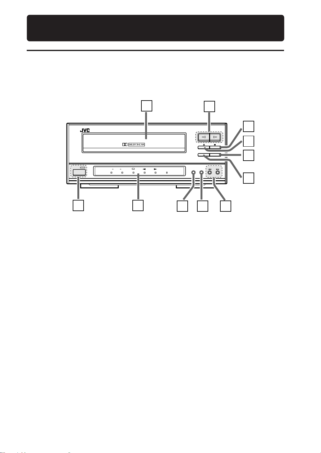
Front Panel
TD-EX90 CASSETTE DECK
AUTO REVERSE
STANDBY
POWER
DOLBYBC
1
1 POWER switch
Press to switch the power between ON and
STANDBY.
STANDBY indicator
The indicator is off while the power is ON
and lights up when the power is in STANDBY
mode.
2 Indicator panel
3 DOLBY NR button
Press to activate Dolby Noise Reduction.
Each press switches Dolby NR to type B,
type C and Off.
4 REVERSE MODE button
Press to switch the tape transport mode.
5 1, ¡ buttons
Press to skip to the beginning of a desired
track or to fast forward or fast reverse a tape.
6 REC PAUSE button
Press to enter record-pause mode.
7 CD REC button
Press for synchronized recording with the EX
series CD player.
11
10
9
8
CD REC
REC PAUSE
7
REVERSE
REC
DOLBY
MODE
NR
6
2
8 0 button
9 7 button
p ¤, ‹ buttons
q Tape tray
3 4 5
Press to open or close the tape tray.
Press to stop tape playback or recording.
Press to start tape playback or recording.
A cassette tape is placed here.
5 TD-EX90
Page 6
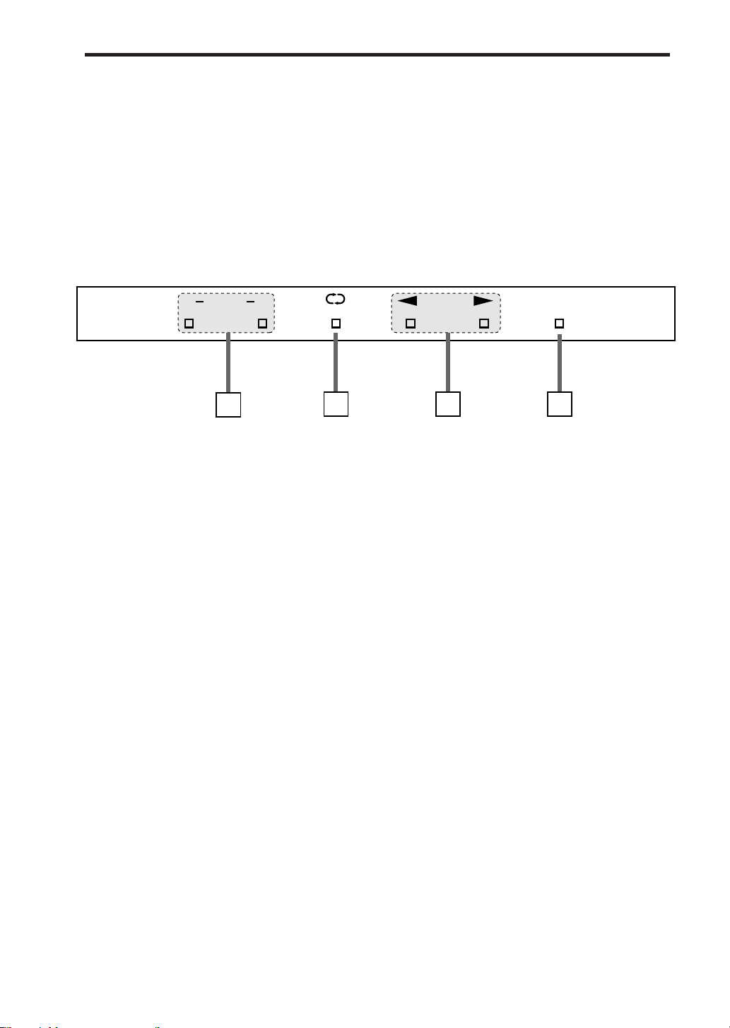
Display
RECDOLBYBC
1
2
1 Dolby Noise Reduction indicators
B: Lights when Dolby NR type B is selected.
C: Lights when Dolby NR type C is selected.
2 Reverse mode indicators
On: • During playback, both sides of the
tape are played repeatedly.
• During recording with forward
direction( £), one side of the tape
will be recorded first then the other
side, and stopped.
• During recording with reverse
direction (™ ), one side of the tape
will be recorded and stopped.
Off: • Playback or recording stops at the end
of the tape (one side).
34
3 Tape operation indicators
These indicators show the tape transport
direction and operation status.
•Slow blinking: During playback or recording.
•Quick blinking: During fast forward or
rewind.
•Rhythmical blinking: During search(Music
Scan).
4 Recording indicator
The REC indicator lights in red in recordpause and record modes.
6 TD-EX90
Page 7
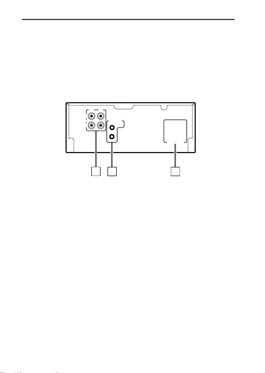
Rear Panel
IN
(REC)
ANALOG
OUT
(PLAY)
RIGHT LEFT
COMPU LINK-3
(SYNCHRO)
AC POWER CORD
1
1 ANALOG input/output jacks
Connect to the TAPE input/output jacks of
the amplifier/tuner using the provided audio
pin cords.
Connect the IN (REC) jacks to the OUT (REC)
jacks of the amplifier/tuner and the OUT
(PLAY) jacks to its IN (PLAY) jacks.
2 COMPU LINK-3 (SYNCHRO) jacks
Connect each jack with the provided COMPU
LINK-3 (SYNCHRO) jack of another
component.
Either jack can be used for the connection.
2
3
3 AC POWER CORD receptacle
Connect the provided AC power cord.
7 TD-EX90
Page 8

Setting Up the System
Supplied Accesories
AC power cord x 1
Audio pin cords x 2
Compu Link cable x 1
Caution for Placement
Do not place in any of the following ares.
• In direct sunlight.
• Do not place the CD player on top of the amplifer/tuner.
• In a place warmer than 35°C (95F°).
• In a bathroom, kitchen or other area with steam, humidity, or hot water.
• In a place with lots of static electricity or dust.
• In an unstable area.
• Near appliances that receive electronic wave broadcasts, such as a television.
Special attention
To protect from damage or malfunction,do not place this cassette deck on an amplifier or equivalent
to generate heat.
TD-EX90 CASSETTE DECK
STANDBY
DOLBYBC
POWER
CD REC
REC PAUSE
REVERSE
DOLBY
REC
MODE
NR
Cassette deck
Amplifier
8 TD-EX90
Page 9

Connections
INTEGRATED AMPLIFIER / TUNER
Amplifier/Tuner
@
VOLUME
BAND
PHONES
STANDBY
DIRECTS. A. BASS
DOWN
INPUT
UP
KEY
MODE
Audio pin cords
Always connect the jacks with the plugs of the
same colors so as not to mistake the L (Left) and
R (Right) connections.
Connect the OUT (PLAY) jacks to the IN (PLAY)
jacks of the amplifier/tuner, and the IN (REC)
jacks to its OUT (REC) jacks.
RIGHT LEFT
IN
(REC)
ANALOG
OUT
(PLAY)
COMPU LINK-3
(SYNCHRO)
AC POWER CORD
Compu Link cable
Connect to the COMPU
LINK-3 (SYNCHRO) jack of
another component
equipped with Compu Link
remote control system.
9 TD-EX90
Page 10

Playback
Tape playback
Three tape types including normal (Type I), High position (Type II) and Metal (Type IV) tapes can be
played back. The type of tape is identified automatically by the cassette deck.
1 Press 0.
The tape tray comes out open.
Shortcut:
Pressing 0 while the power is in the STANDBY mode
automatically switches the power ON and opens the
tape tray.
2 Place a tape on the tray, with the side A facing
up.
Fit in the caved-in area so that the edge where tape is
exposed faces toward the inside of the unit.
3 Press 0.
The tape tray closes.
4 Press ¤ or ‹.
Playback starts.
• Pressing ‹ starts playback of side A (top side). The
£ indicator blinks slowly.
Pressing ¤ starts playback of side B (bottom side).
The ™ indicator blinks slowly.
• If ¤ or ‹ is pressed while the tape tray is open, the
tape tray closes before playback starts.
Shortcut
Pressing ¤ or ‹ while the power is in the STANDBY
mode automatically switches the power ON and starts
playback.
Note: It will take about 6 seconds to start playing.
• Press 7 to stop playback in the middle.
• Press 0 to eject the tape.
Caution
Playback may be interfered with noise if there is a TV set nearby. In this case, turn off the TV or
increase the distance between the TV and this unit.
10 TD-EX90
Page 11

To fast forward or rewind tape:
Press 1 or ¡ while tape is in stop mode. The tape
indicator blinks at a high speed during fast forward or
rewind operation.
Fast forward
If the current tape transport direction is £, press ¡.
If the current tape transport direction is ™, press 1.
Rewind
If the current tape transport direction is £, press 1.
If the current tape transport direction is ™, press ¡.
Skipping to the beginning of music (Music Scan)
The beginning of the piece of music located before or
after the current playback position can be located easily
by making use of blanks between music.
Press 1 or ¡ while tape is in play mode. The tape
indicator blinks rhythmically during skip operation.
Skipping to the beginning of next music
If the current tape transport direction is £, press ¡.
If the current tape transport direction is ™, press 1.
Skipping to the beginning of current music being
played
If the current tape transport direction is £, press 1.
If the current tape transport direction is ™, press ¡.
• The beginning of the desired music may not be
located properly if blanks between music are too
short, the blanks contain too much noise or the music
itself contains very low-level or silent part.
DOLBY
NR
DOLBY
NR
REVERSE
MODE
REVERSE
MODE
To play both sides of tape continuously:
Press REVERSE MODE.
The reverse mode indicator (π) lights up when the
reverse mode is on, and turns off when it is off.
When the reverse mode is on
The two sides of tape will be played continuously and
repeatedly.
When the reverse mode is off
Tape stops after one side has been played.
To play a tape recorded using Dolby NR:
Press DOLBY NR.
Each press switches the Dolby NR mode as shown
below.
DOLBY B NR
(Indicator lit)
Off (Canceled)
Select B or C according to the Dolby NR type used
when the tape was recorded. The indicator of the
selected type should light up.
The Dolby NR allows to reduce hiss noise in playback.
Dolby Noise Reduction manufactured under license
from Dolby Laboratories Licensing Corporation.
“Dolby” and the double-D symbol are registered
trademarks of Dolby Laboratories Licensing
Corporation.
DOLBY C NR
(Indicator lit)
11 TD-EX90
Page 12

Recording
Tape recording (Basic operation)
Three tape types including normal (Type I), High position (Type II) and Metal (Type IV) tapes can be
recorded onto. The type of tape is identified automatically by the cassette deck.
1 Load the tape for use in recording, with the
side A facing up.
Press 0 to open the tape tray, place a tape on it and
press 0 to close it.
• It is not possible to record onto a cassette tape with
the broken accidental erasure tab. Use a cassette the
tab of which is not broken.
2 Prepare the recording source (Tuner, CD or
MD, etc.).
• To record radio broadcast, receive a station with the
tuner.
• To record CDs, load the desired CDs and program
tracks if required.
• To record an MD, load the desired MD and program
tracks if required.
• To record a component connected to AUX, prepare it
as required.
* Refer to the instruction manual of the source
component for its operating procedure.
3 Select the recording source with the
CD RECREC PAUSE
amplifier’s input selector.
4 Press REC PAUSE.
The REC indicator lights in red to indicate record-pause
mode.
5 Start playing the source component.
If you want to record CD or MD tracks from the first
track, first perform step 6 below (i.e. start recording)
then start playing the source.
6 Press ¤ or ‹.
• Pressing ‹ starts recoding on side A (top side).
• Pressing ¤ starts recoding on side B (bottom side).
The tape indicator starts blinking to indicate that the
recording is under way.
• The recording level is set automatically.
• Press 7 to stop recording.
• Press 0 to eject the tape.
12 TD-EX90
Page 13

To let recording pause temporarily:
Press REC PAUSE. The tape indicator stops blinking and
lights steadily.
Press ¤ or ‹ to resume recording.
To record continuously on both sides of tape:
1 Load a tape so that you can start recording from the
£ direction.
2 Press REVERSE MODE to switch the reverse mode
on.
Press so that the reverse mode indicator (π) lights up.
3 Prepare recording of the associated components.
4 Press REC PAUSE.
5 Press ‹ to start recording.
• The recording in the reverse mode stops after
completing recording in the ™ direction. Be sure to
start recording from the £ direction.
• When the reverse mode is switched off, recording
stops after having recorded onto one side of tape.
Note: The side erasure tab is removed (refer to P.19)
will not be recorded even though the reverse
mode is swithed on.
To record audio using Dolby NR
The Dolby NR is used to record audio to reduce hiss noise
when the tape is played back later. The Dolby NR includes
type B for popular use and type C for even improved noise
reduction effect.
Press DOLBY NR so that either the B or C indicator lights
up.
DOLBY B NR
(Indicator lit)
Off (Canceled)
• A tape recorded using Dolby NR should be played
back using the Dolby NR of the same type as that
used in recording. The audio quality will be affected if
a different type is used in playback.
DOLBY C NR
(Indicator lit)
13 TD-EX90
Page 14

CD synchronized recording
CDs can be recorded with a simple, one-touch operation. By using the features of the CD player
you can easily create an original tape of your favorite music.
Be sure to make the Compu Link connection among the EX series components.
1 Load the tape for use in recording.
Press 0 to open the tape tray, place a tape on it and
press 0 to close it.
• It is not possible to record onto a cassette tape with
the broken accidental erasure tab. Use a cassette the
tab of which is not broken.
• If you want to record music on both sides of tape
continuously, switch the reverse mode on (see page
13).
• If you want to use Dolby Noise Reduction, press
DOLBY NR to select B or C (see page 13).
2 Prepare the CD player.
Load CDs, press CD 1, 2 or 3 according to the disc you
want to record, and press &/CANCEL of the CD player.
This selects the playing CD.
Now set the CD player to the program play mode, etc.,
as required.
* Refer to the instruction manual of the CD player for
the CD player operating procedures.
CD RECREC PAUSE
3 Press CD REC.
The CD player and cassette deck start simultaneously
and synchronized recording starts.
• During recording, the CD source is selected
automatically by the amplifier/tuner.
• During recording, the amplifier/tuner’s input source
cannot be changed even by pressing its INPUT.
14 TD-EX90
To stop recording:
Press &/CANCEL of the CD player to stop recording.
The cassette deck will stop after leaving a non-recorded
blank of 4 seconds.
If you want to stop recording immediately, press 7 of
the cassette deck.
Page 15

MD synchronized recording
Synchronized recording makes it possible to start cassette recording in synchronism with the
playback of the MD recorder.
Be sure to make the Compu Link connection among the EX series components.
1 Load the tape for use in recording.
Press 0 to open the tape tray, place a tape on it and
press 0 to close it.
• It is not possible to record onto a cassette tape with
the broken accidental erasure tab. Use a cassette the
tab of which is not broken.
• If you want to record music on both sides of tape
continuously, switch the reverse mode on (see page
13).
• If you want to use Dolby Noise Reduction, press
DOLBY NR to select B or C (see page 13).
2 Prepare the MD recorder.
Load the MD to be played.
Program MD tracks if required.
* Refer to the instruction manual of the MD recorder
for the MD recorder operating procedures.
CD RECREC PAUSE
3 Press REC PAUSE.
The cassette deck enters record-pause mode.
/CANCEL
4 Press ‹/8 of the MD recorder.
Synchronized recording starts.
To stop recording:
Press &/CANCEL of the MD recorder to stop recording.
The cassette deck will stop after leaving a non-recorded
blank of 4 seconds.
If you want to stop recording immediately, press 7 of
the cassette deck.
15 TD-EX90
Page 16

COMPU LINK
Linked Operation of the Other Optional components (Compu Link)
The EX series components can be controlled under linked operation provided by the JVC’s Compu
Link remote control system.
Compu Link
The world of single components, in which you purchase a cassette deck, CD player, amplifier and
other components separately and enjoy your own composition, is an effective means for pursuit
of high-quality reproduction. However, in terms of operability, the need of controlling components
independently makes their control complicated and their linked operation impossible. Then, isn’t it
possible to combine single components and control them as simply as an integrated audio
system? The Compu Link remote control system is the response to such a requirement.
The components in the JVC EX series are equipped with jacks named COMPU LINK-3 (COMPU
LINK jacks). By connecting the COMPU LINK jacks of these components, they can be controlled
simply with a systematized, linked operation.
Compu Link connections
Using Compu Link cables, connect the COMPU LINK jacks of EX series components. Connect so that
the Compu Link cables can bridge all of the EX series components you have. The components can be
connected in any order.
16 TD-EX90
Page 17

Compu Link-3 features
The Compu Link-3 system of the EX series components makes the following operations possible.
Shortcut playback
Simply selecting an input source of the amplifier/tuner starts playback of the selected source
component (CD player, MD recorder or cassette deck).
Also, even if you do not touch the amplifier/tuner, starting playback of a source component sets
the amplifier’s input source automatically to the played component.
* Refer to the instruction manual of the amplifier/tuner.
System control from a single remote control unit
The remote control unit provided with the amplifier/tuner can also be used to control the CD
player or cassette deck.
Synchronized recording
Recording can be started automatically in synchronism with the start of playback of a source
component.
(See pages 14 and 15.)
Timer operation
The timer function built into the amplifier/tuner can be used to start recording or playback of other
components at the reserved time of the day or switch the power to the STANDBY mode in the
reserved time period.
* Refer to the instruction manual of the amplifier/tuner.
17 TD-EX90
Page 18

Additional Information
Types of cassette tape
This cassette deck incorporates an auto tape select function. The auto tape select function uses the
tape-type detection holes to distinguishes which type of tape was inserted, and sets the bias and
equalizer to the optimum settings for that tape automatically.
The following types of tapes may be used with this cassette deck.
Normal tape
TYPE I
BIAS:NORMAL
EQ:120µs
Normal (No detection slots)
Tab
(to prevent accidental erasure)
High Position (CrO2) tape
TYPE II
BIAS:HIGH
EQ:70µs
High position
detection slots
Metallic tape
TYPE IV
BIAS:METAL
EQ:70µs
Metal detection slots
Caution
• Tapes longer than 90 minutes, such as C-120 or C-150 tapes, are extremely thin and stretch easily.
Please note that frequent rewinding and fast forwarding of small sections of tape may cause
these tapes to jam in the pinch rollers and capstans.
Note: The use of these types of tapes is not recommended to avoid troubles.
• Certain early period metal and high position (CrO2) tapes may not have tape-type detection slots.
The cassette deck cannot obtain the correct characteristics for these tapes.
• Ferrochromite (FeCr) TYPE III tapes cannot be used with this cassette deck.
18 TD-EX90
Page 19

Handling cassette tapes
Cautions regarding handling
Do not touch the surface of the tape or pull
the tape out of the cassette.
Tape spooled loosely around the hubs is likely
to jam in the pinch rollers and capstans.
Before loading the tape into the cassette
holder, take up the slack in the tape as shown
below.
Maintenance
Cleaning the tape heads
Since the tape is always touching the heads
as it travels through the tape transport, in
time magnetic particles and dust build up,
making the heads dirty. When the heads
become extremely dirty, the sound quality
becomes poor, the output level is reduced,
recording doesn’t work, and previously
recorded sounds cannot be erased (etc.).
In order to prevent important recordings
from coming out as failures, we recommend
cleaning the heads, pinch rollers and
capstans on a regular basis (after about
every 10 hours of use), before the
symptoms described above begin to appear.
Tape storage
Place tapes in their cases for storage.
Avoid storing tapes on top of TVs or
speakers, in sunlight or places of high
temperature, or in humid or dusty areas.
To prevent accidental erasure
Cassette tapes have tabs to prevent
accidental erasure.
If you remove the tabs after making a
recording, the cassette deck cannot be set to
record when that tape is loaded. Remove the
tabs so that valuable recordings will not be
accidentally erased.
Recording (erasure) is not possible when the
tabs are removed.
Tab for side A
Tab for side B
To make another recording on a tape whose
tabs have been removed, cover the tab holes
with adhesive tape.
Cleaning method
Clean the heads, capstans and pinch rollers
using a wet-type head cleaning tape,
available from an audio store. For more
details, refer to the Instructions of the Head
Cleaning Tape.
Demagnetizing the tape heads
After the cassette deck has been used for
long period of time, the metal parts which
contact the tape may become magnetically
charged. When this occurs, tape hiss
increases, and the high pitched sounds on
recorded tapes will be erased. The same
type of malfunction could also be caused by
bringing a charged metal object (such as a
screwdriver) near the tape heads.
We recommend demagnetizing the tape
heads regularly (after about every 20 to 30
hours of use) with a commercially available
tape head demagnetizer.
You may also use cassette type
demagnetizers with this cassette deck.
When doing so, be sure to turn the volume
of the amplifier all the way down, or you may
harm the amplifier or speakers.
For details, read the instructions that come
with the tape head demagnetizer.
Tape type detection slot
Adhesive tape
Be careful not to cover the tape-type
detection slots.
19 TD-EX90
Page 20

Troubleshooting
If you experience any difficulty with your cassette deck, check the following list for a possible
solution before calling for service.
If you cannot solve the problem from the hints given here, or the cassette deck has been physically
damaged, call a qualified person, such as your dealer, for service.
SYMPTOM
Recording is not possible
No sound
Music scan does not work
Sound level is low or sound is
intermittent
Tape hiss or absence of high
frequency sounds
Previously recorded material is
not erased when recorded over
Bad sound quality or absence
of high frequency sounds
Cassette holder will not open
(or close)
Humming noise
Operation is abnormal.
POSSIBLE CAUSE
• The tabs on the cassette
have been removed.
• The deck is set to pause.
• Connections are incorrect or
incomplete.
• Volume control on amplifier
is turned all the way down.
• The source selector (INPUT)
on the amplifier is set to a
different source.
• The blank spaces between
songs is too short.
• The heads, capstans, and
pinch rollers are dirty.
• The play and record heads
have become magnetically
charged.
• The erase head is dirty.
• The Dolby NR setting is
different from that used for
recording.
• The AC power cord is
unplugged.
• Cassette deck is directly
above or below the
amplifier/tuner.
• Condensation is produced
inside the cassete deck
immediately after starting
the room heating or when it
is transported from a cold to
warm place.
• The microcomputer is
malfunctioning due to
external noise or lightning.
ACTION
• Use a different cassette
tape.
• If you don’t mind erasing
the previously recorded
material, cover the holes
with tape.
• Press ¤ or ‹ to release
the pause.
• Check to make sure the all
equipment is connected
correctly.
• Adjust the volume on the
amplifier.
• Set the source selector
(INPUT) to tape.
• Try a different cassette
tape.
• Clean the heads, capstans,
and pinch rollers.
• Demagnetize the heads.
• Clean the erase head.
• Set the Dolby NR to the
same setting used for
recording.
• Plug the AC power cord into
a wall outlet.
• Move cassette deck away
from amplifier/tuner.
• Unplug the power cord,
wait a few hours and plug it
again.
• Unplug the power cord then
plug it in again.
20 TD-EX90
Page 21

Specifications
Audio performance
Frequency response (–20 dB recording)
Input/Output Terminals
General
Signal-to-noise ratio
Wow and flutter
ANALOG IN (REC)
ANALOG OUT (PLAY)
Type IV tape :30 Hz to 17 kHz (40Hz to 17kHz ( 3 dB))
Type I I tape :30 Hz to 16 kHz (40Hz to 16kHz ( 3 dB))
Type I tape :30 Hz to 15 kHz (40Hz to 15kHz ( 3 dB))
54 dB
(S=315 Hz , k3=3% , N=A-weighted , Type IV tape)
The S/N is improved by about 15 dB at 500 Hz and
by max. 20 dB at 1 kHz to 10 kHz with Dolby C NR
on and improved by 5 dB at 1 kHz and by 10 dB at
above 5 kHz with Dolby B NR on. MOL Improved 4
dB at 10kHz
0.09%(WRMS)
Input level / Impedance : 220mV (0 VU) / 19 kohms
Output level / Impedance : 300mV (0 VU) / 2.9 kohms
Accessories
Format
Track System
Tape Speed
Heads
Motors
Fast forward / Rewind time
Power requirements
Power Consumption
Dimensions
Mass
Audio pin cord
Compu Link cable
AC power cord
Design and specifications are subject to change without notice.
Compact Cassette Stereo
4-track , 2channel
4.8 cm/sec. (1-7/8inch/sec.)
Record/Playback : METAPERM head × 1
Erase : 2-gap ferrite haed
Capstan : Electronic govemed DC moter
Tray:DC motor × 1
Approx. 120 sec. with C-60 cassette
AC120 60Hz
7watts (OPERETE ON) , 3watts (OPERETE STANDBY)
200 × 80 × 305 mm (W × H × D)
(7-7/8 × 3-3/16 × 12-1/16 inches)
2.4 kg (5,3 lbs)
(2)
(1)
(1)
21 TD-EX90
Page 22

QUALITY SERVICE
HOW TO LOCATE YOUR JVC SERVICE CENTER
TOLL FREE : 1-800-537-5722
Dear customer:
In order to receive the most satisfaction from your purchase, read the instruction booklet before operating the unit. In the event that
repair is necessary, or for the address nearest your location, please refer to the factory service center list below or within the Continental
United States, Call 1-800-537—5722 for your authorized servicer. Remember to retain you Bill of Sale for Warranty Service.
—JVC
JVC SERVICE & ENGINEERING
COMPANY OF AMERICA
DIVISION OF US JVC CORP.
FACTORY SERVICE CENTER LOCATIONS
107 Little Falls Road
Fairfield, NJ 07004-2105
(201) 808-9279
5665 Corporate Avenue
Cypress, CA 90630-0024
(714) 229-8011
230 Eliot Street
Ashland, MA 0172-2377
(508) 881-5923
Sophisticated electronic products may require occasional service. Just as quality is a keyword in the engineering and production of
the wide array of JVC products, service is the key to maintaining the high level of performance for which JVC is world famous. The
JVC service and engineering organization stands behind our products.
1500 Lakes Parkway
Lawrenceville, GA 30243-5357
(770) 339-2522
2969 Mapunapuna Place
Honolulu, HI 96819-2040
(808) 833-5828
14505 Commerce Way
Miami Lakes, FL 33016-1512
(305) 362-6252
NATIONAL HEADQUARTERS
JVC SERVICE & ENGINEERING COMPANY OF AMERICA
DIVISION OF US JVC CORP.
107 Little Falls Road
Fairfield, NJ 07004-2105
If you ship the product • • •
Pack your JVC unit in the original carton or one of equivalent
size and strength. Enclose, with the unit, a letter stating the
problem or symptom that exists and also a copy of the receipt
or bill of sale you received when you purchased your JVC unit.
Print your home return address on the outside and the inside
of the carton. Send to the appropriate JVC Factory Service
Center as listed above.
To prevent electrical shock, do not open the cabinet. No user
serviceable parts inside.
Refer servicing to qualified service personnel.
705 Enterprise Street
Aurora, IL 60504-8149
(630) 851-7855
10700 Hammerly, Suite 110
Houston, TX77043
(713) 935-9331
890 Dubuque Avenue
South San Francisco, CA 94080-1804
(415) 871-2666
Don’t service it yourself.
CAUTION
ACCESSORIES
To purchase accessories for your JVC product, you may contact your local JVC Dealer.
Or from the 48 Continental United States call toll free : 800-882-2345
(0694)
22 TD-EX90
Page 23

LIMITED W ARRANTY
JVC COMPANY OF AMERICA warrants this product and all parts thereof, except as set forth below ONLY TO THE ORIGINAL
PURCHASER AT RETAIL to be FREE FROM DEFECTIVE MATERIAL AND WORKMANSHIP from the date of original retail
purchase for the period as shown below. (“The Warranty Period.”)
PARTS LABOR
THIS LIMITED WARRANTY IS VALID ONLY IN THE FIFTY(50) UNITED STATES, THE DISTRICT OF COLUMBIA AND IN
COMMONWEALTH OF PUERTO RICO.
WHAT WE WILL DO:
If this product is found to be defective, JVC will repair or replace defective parts at no charge to the original owner. Such
repair and replacement services shall be rendered by JVC during normal business hours at JVC authorized service centers.
Parts used for replacement are warranted only for the remainder of the Warranty Period. All products and parts thereof may be
brought to a JVC authorized service center on a carry-in basis except for Television sets having a screen size 25 inches and
above which are covered on an in-home basis.
WHAT YOU MUST DO FOR WARRANTY SERVICE:
Return your product to a JVC authorized service center with a copy of your bill of sale. For your nearest JVC authorized
service center, please call toll free: (800)537-5722.
If service is not available locally, box the product carefully, preferably in the original carton, and ship, insured, with a copy of
your bill of sale plus and letter of explanation of the problem to the nearest JVC Factory Service Center, the name and location
of which will be given to you by the toll-free number.
If you have any questions concerning your JVC Product, please contact our Customer Relations Department.
WHAT IS NOT COVERED:
This limited warranty provided by JVC
1. Products which have been subject to abuse, accident, alteration, modification, tampering, negligence, misuse, faulty
installation, lack of reasonable care, or if repaired or serviced by anyone other than a service facility authorized by JVC to
render such service, or if affixed to any attachment not provided with the products, or if the model or serial number has
been altered, tampered with, defaced or removed;
2. Initial installation and installation and removal for repair;
3. Operational adjustments covered in the Owner’s Manual, normal maintenance, video and audio head cleaning;
4. Damage that occurs in shipment, due to act of God, and cosmetic damage;
5. Signal reception problems and failures due to line power surge;
6. Video Pick-up Tubes/CCD Image Sensor, Cartridge, Stylus(Needle) are covered for 90 days from the date of purchase;
7. Accessories;
8. Batteries (except the Rechargeable Batteries are covered for 90 days from the date of purchase);
There are no express warranties except as listed above.
THE DURATION OF ANY IMPLIED WARRANTIES, INCLUDING THE IMPLIED WARRANTY OF MARCHANTABILITY, IS
LIMITED TO THE DURATION OF THE EXPRESS WARRANTY HEREIN.
JVC SHALL NOT BE LIABLE FOR THE LOSS OF USE THE PRODUCT, INCONVENIENCE, LOSS OR ANY OTHER
DAMAGES, WHETHER DIRECT, INCIDENTAL OR CONSEQUENTIAL (INCLUDING, WITHOUT LIMITATION, DAMAGE TO
TAPES, RECORDS OR DISCS) RESULTING FROM THE USE OF THIS PRODUCT, OR ARISING OUT OF ANY BREACH
OF THIS WARRANTY. ALL EXPRESS AND IMPLIED WARRANTIES, INCLUDING THE WARRANTIES OF
MERCHANTABILITY AND FITNESS FOR PARTICULAR PURPOSE, ARE LIMITED TO THE WARRANTY PERIOD SET
FORTH ABOVE.
Some states do not allow the exclusion of incidental or consequential damages or limitations on how long an implied
warranty last, so these limitations or exclusions may not apply to you. This warranty gives you specific legal rights and you
may also have other rights which vary from state to state.
JVC COMPANY OF AMERICA 41 Slater Drive
DIVISION OF US JVC CORP. Elmwood Park, New Jersey 07407
does not cover:
1YR 1YR
AUDIO-1
REFURBISHED PRODUCTS CARRY A SEPARATE WARRANTY, THIS WARRANTY
REFURBISHED PRODUCT WARRANTY, PLEASE REFER TO THE REFURBISHED PRODUCT WARRANTY INFORMATION
PACKAGED WITH EACH REFURBISHED PRODUCT.
For customer use:
Enter below the Model No. and Serial No. which is located either on the rear, bottom or side of the cabinet. Retain this
information for future reference.
Model No.: Serial No.:
Purchase date: Name of dealer:
DOES NOT APPLY. FOR DETAILS OF
23 TD-EX90
Page 24

VICTOR COMPANY OF JAPAN, LIMITED
EN.
JVC
0598TTMWSTOZK
 Loading...