

Page 1
DIGITAL MEDIA SYSTEM
TH-L1
Consists of AX-THL1, SP-THL1W,
SP-THL1F, SP-THL1C and SP-THL1S
INSTRUCTIONS
For Customer Use:
Enter below the Model No. and Serial
No. which are located either on the rear,
bottom or side of the cabinet. Retain this
information for future reference.
Model No.
Serial No.
GVT0206-001A
[J, C]
Page 2
Warnings, Cautions and Others
Mises en garde, précautions et indications diverses
CAUTION— button!
Disconnect the mains plug to shut the power off
completely (the STANDBY lamp goes off). When
installing the apparatus, ensure that the plug is easily
accessible.
The button in any position does not disconnect the
mains line.
• When the system is on standby, the STANDBY lamp
lights red.
• When the system is turned on, the STANDBY lamp
goes off.
The power can be remote controlled.
ATTENTION—Touche
Déconnectez la fiche secteur pour mettre l’appareil
complètement hors tension (le témoin STANDBY
s'éteint). Lors de l’installation de l’appareil, assurezvous que la fiche soit facilement accessible.
La touche , dans n’importe quelle position, ne
déconnecte pas le système du secteur.
• Quand le système est en attente, le témoin
STANDBY est allumé en rouge.
• Quand le système est sous tension, le témoin
STANDBY s'éteint.
L'alimentation peut être télécommandée.
CAUTION
To reduce the risk of electrical shocks, fire, etc.:
1. Do not remove screws, covers or cabinet.
2. Do not expose this appliance to rain or moisture.
ATTENTION
Afin d’éviter tout risque d’électrocution, d’incendie,
etc.:
1. Ne pas enlever les vis ni les panneaux et ne pas
ouvrir le coffret de l’appareil.
2. Ne pas exposer l’appareil à la pluie ni à l’humidité.
[European Union only]
[Union européenne seulement]
G-1
Page 3

Warnings, Cautions and Others/Mises en garde, précautions et indications diverses
For U.S.A.
This equipment has been tested and found to comply with
the limits for a Class B digital device, pursuant to part 15
of the FCC Rules. These limits are designed to provide
reasonable protection against harmful interference in a
residential installation.
This equipment generates, uses and can radiate radio
frequency energy and, if not installed and used in
accordance with the instructions, may cause harmful
interference to radio communications. However, there is
no guarantee that interference will not occur in a
particular installation. If this equipment does cause
harmful interference to radio or television reception,
which can be determined by turning the equipment off
and on, the user is encouraged to try to correct the
interference by one or more of the following measures:
Reorient or relocate the receiving antenna.
– Increase the separation between the equipment and
receiver.
– Connect the equipment into an outlet on a circuit
different from that to which the receiver is connected.
– Consult the dealer or an experienced radio/TV
technician for help.
CAUTION
Changes or modifications not approved by JVC could
void the user’s authority to operate the equipment.
CAUTION
Excessive sound pressure from earphones or headphones
can cause hearing loss.
CAUTION
• Do not block the ventilation openings or holes.
(If the ventilation openings or holes are blocked by a
newspaper or cloth, etc., the heat may not be able to
get out.)
• Do not place any naked flame sources, such as
lighted candles, on the apparatus.
• When discarding batteries, environmental problems
must be considered and local rules or laws governing
the disposal of these batteries must be followed
strictly.
• Do not expose this apparatus to rain, moisture,
dripping or splashing and that no objects filled with
liquids, such as vases, shall be placed on the
apparatus.
ATTENTION
• Ne bloquez pas les orifices ou les trous de
ventilation. (Si les orifices ou les trous de ventilation
sont bloqués par un journal un tissu, etc., la chaleur
peut ne pas être évacuée correctement de l’appareil.)
• Ne placez aucune source de flamme nue, telle
qu’une bougie, sur l’appareil.
• Lors de la mise au rebut des piles, veuillez prendre
en considération les problèmes de l’environnement
et suivre strictement les règles et les lois locales sur
la mise au rebut des piles.
• N’exposez pas cet appareil à la pluie, à l’humidité, à
un égouttement ou à des éclaboussures et ne placez
pas des objets remplis de liquide, tels qu’un vase, sur
l’appareil.
ATTENTION
Une pression acoustique excessive des écouteurs ou du
casque d’écoute peut entraîner une perte auditive.
For Canada/pour le Canada
THIS DIGITAL APPARATUS DOES NOT EXCEED
THE CLASS B LIMITS FOR RADIO NOISE
EMISSIONS FROM DIGITAL APPARATUS AS SET
OUT IN THE INTERFERENCE-CAUSING
EQUIPMENT STANDARD ENTITLED
APPARATUS,” ICES-003 OF THE DEPARTMENT OF
COMMUNICATIONS.
CET APPAREIL NUMERIQUE RESPECTE LES
LIMITES DE BRUITS RADIOELECTRIQUES
APPLICABLES AUX APPAREILS NUMIRIQUES DE
CLASSE B PRESCRITES DANS LA NORME SUR LE
MATERIEL BROUILLEUR;
NUMERIQUES”, NMB-003 EDICTEE PAR LE
MINISTRE DES COMMUNICATIONS.
“APPAREILS
“DIGITAL
G-2
Page 4
Warnings, Cautions and Others/Mises en garde, précautions et indications diverses
Caution: Proper Ventilation
To avoid risk of electric shock and fire and to protect from damage, place the apparatus on a level surface. The minimal
clearances are shown below:
Attention: Ventilation Correcte
Pour éviter les chocs électriques, les incendies et tout autre dégât, poser l’appareil sur une surface plate. Le dégagement
minimum est indiqué ci-dessous:
Wall or obstructions
Mur, ou obstruction
Front view/Face
15 cm
(5-15/16")
15 cm
(5-15/16")
AX-THL1
15 cm
(5-15/16")
15 cm
(5-15/16")
Side view/Côté
Wall or obstructions/Mur, ou obstruction
AX-THL1
Front
Avant
No obstructions
Aucune
obstruction
15 cm
(5-15/16")
G-3
Page 5

Table of contents
Introduction ...........................................2
Notes on handling ......................................................... 2
Supplied accessories ...................................................... 2
About files ..............................................3
Playable file types for the USB MEMORY ................ 3
Index of parts and controls ...................4
Front panel (center unit) .............................................. 4
Rear panel (center unit) ............................................... 5
Remote control .............................................................. 6
Connections ............................................7
Connecting the speakers and subwoofer ................... 7
Speaker layout ................................................................ 8
Connecting a TV ........................................................... 9
Connecting the video components for the source of
VIDEO 1........................................................................ 10
Connecting the video components for the source of
VIDEO 2........................................................................ 11
Connecting the video components for the source of
VIDEO 3........................................................................ 12
Connecting a USB mass storage class device .......... 13
Connecting the iPod .................................................... 13
Connecting the power cord ....................................... 13
Operating the TV and DVD player ......14
Operating the TV ........................................................ 14
Operating the DVD player ........................................ 15
Basic operations .................................. 16
Turning the system on/off ..........................................16
Selecting the source to play ........................................16
Adjusting the volume [VOLUME] ............................17
Listening with headphones (not supplied) ...............17
Turning off the sound temporarily [MUTING] ......17
Adjusting the brightness of the indications
[DIMMER] ...................................................................17
Sleep Timer [SLEEP] ...................................................17
Adjusting the output level of the speakers and
subwoofer ......................................................................18
Changing the scanning mode .....................................18
Operations for iPod .............................19
Playing an iPod .............................................................19
Operations for USB MEMORY .............21
Basic operations for USB MEMORY ........................21
Advanced operations for USB MEMORY ................24
Operations for surround mode ...........27
Using the surround mode ...........................................27
Setting preferences .............................29
Using the setup menus ................................................29
Menu description .........................................................29
Setting the audio terminal ..........................................31
References ............................................32
Troubleshooting ...........................................................32
Specifications ................................................................33
I
1
Page 6

Introduction
Notes on handling
7 Important cautions
Installation of the system
• Select a place which is level, dry and neither too hot nor
too cold; between 5°C and 35°C (41°F and 95°F).
• Leave sufficient distance between the system and the TV.
• Do not use the system in a place subject to vibration.
Power cord
• Do not handle the power cord with wet hands.
• A small amount of power is always consumed while the
power cord is connected to the wall outlet.
• Do not pull on the power cord to unplug the cord. When
unplugging the cord, always grasp and pull the plug so as
not to damage the cord.
To prevent malfunctions of the system
• There are no user-serviceable parts inside. If anything
goes wrong, unplug the power cord and consult your
dealer.
• Do not insert any metallic object into the system.
Note about copyright laws
Check the copyright laws in your country before recording
from original sources. Recording of copyrighted material
may infringe copyright laws.
7 Safety precautions
Avoid moisture, water and dust
Do not place the system in moist or dusty places.
Avoid high temperatures
Do not expose the system to direct sunlight and do not
place it near a heating device.
When you are away
When away on travel or for other reasons for an extended
period of time, disconnect the power cord plug from the
wall outlet.
Do not block the vents
Blocking the vents may damage the system.
Care of the cabinet
• Stains on the system should be wiped off with a soft cloth.
If the system is heavily stained, wipe it with a cloth
soaked in water diluted neutral detergent and wrung well,
then wipe clean with a dry cloth.
• Since the system may deteriorate in quality, become
damaged or get its paint peeled off, be careful about the
following.
–DO NOT wipe it forcefully.
–DO NOT wipe it with thinner, benzine or other organic
solvents including disinfectants.
–DO NOT apply any volatile substance such as
insecticides to it.
–DO NOT allow any rubber or plastic to remain in
contact with it for a long time.
If water gets inside the system
Turn the system off and disconnect the power cord plug
from the wall outlet, then call the store where you made
your purchase. Using the system in this condition may
cause a fire or electrical shock.
Supplied accessories
Check to be sure you have all of the supplied accessories.
The number in parentheses is the quantity of the pieces
supplied.
If anything is missing, contact your dealer immediately.
• Remote control (1)
• Batteries (2)
• Composite Video cord (1)
• Connection cable for iPod (1)
• Stand for iPod (1)
• This product incorporates copyright protection
technology that is protected by U.S. patents and other
intellectual property rights. Use of this copyright
protection technology must be authorized by
Macrovision, and is intended for home and other
limited viewing uses only unless otherwise authorized
by Macrovision. Reverse engineering or disassembly is
prohibited.
• iPod is a trademark of Apple Inc., registered in the U.S.
and other countries.
2
• USE OF THIS PRODUCT IN ANY MANNER THAT
COMPLIES WITH THE MPEG-4 VISUAL
STANDARD IS PROHIBITED, EXCEPT FOR USE BY
A CONSUMER ENGAGING IN PERSONAL AND
NON-COMMERCIAL ACTIVITIES.
• Microsoft and Windows Media are either registered
trademarks or trademarks of Microsoft Corporation in
the United States and/or other countries.
• HDMI, the HDMI logo and High-Definition
Multimedia Interface are trademarks or registered
trademarks of HDMI licensing LLC.
• HDCP is the abbreviation of “High-Bandwidth Digital
Content Protection,” and is the high-reliable copy
control technology licensed by Digital Content
Protection, LLC.
Page 7

About files
Playable file types for the USB MEMORY
For all playable files
• The system can only recognize and play files with one of
the following extensions, regardless of the letter case—
upper/lower:
MP3: <.MP3>, <.mp3>
WMA: <.WMA>, <.wma>
WAV : <.WAV>, <.WAVE>, <.wav>, <.wave>
JPEG: <.JPG>, <.JPEG>, <.jpg>, <.jpeg>
MPEG-1/MPEG-2: <.MPG>, <.MPEG>, <.mpg>,
<.mpeg>
ASF: <.ASF>, <.asf>
• The system recognizes up to 150 tracks (files) per group,
99 groups per device, and the total number of the tracks
(files) that the system can play is 4 000.
• Some files may not be played back normally because of
their characteristics or recording conditions.
• Some files require a longer readout time. (It differs due to
the complexity of the directory/file configuration.)
• If different kinds of files are mixed, set the FILE TYPE
setting in the PICTURE menu to the appropriate setting
for the data to be read (“AUDIO”, “STILL PICTURE” or
“VIDEO”). (See page 30.)
For MP3/WMA/WAV files
• The system supports MP3/WMA files recorded at a bit
rate of 32 – 320 kbps and a sampling frequency of 16 kHz,
22.05 kHz, 24 kHz (for WMA only), 32 kHz, 44.1 kHz, or
48 kHz.
• If the track information (album name, artist, and track
title, etc.) is recorded, it appears in the file control display
on the TV screen. (See page 24.)
• It is recommended that you make each MP3/WMA/WAV
files at the following conditions:
MP3/WMA: At a sample rate of 44.1 kHz and bit rate of
128 kbps.
WAV : 44.1 kHz/16 bit Linear PCM.
For JPEG files
• It is recommended that you record a file at 640 x 480
resolution. (If a file has been recorded at a resolution of
more than 640 x 480, it will take a longer time to be
displayed.)
• This system can only play baseline JPEG files.
For MPEG-1/MPEG-2 files
• The stream format should conform to MPEG system/
program stream.
• 720 x 576 pixels (25 fps)/720 x 480 pixels (30 fps) is
recommended for the highest resolution.
• This system also supports the resolutions of 352 x 576/
480 x 576/352 x 288 pixels (25 fps) and 352 x 480/480 x
480/352 x 240 pixels (30 fps).
• The file format should be MP@ML (Main Profile at Main
Level)/SP@ML (Simple Profile at Main Level)/MP@LL
(Main Profile at Low Level).
• Audio streams should conform to MPEG1 Audio Layer-2
or MPEG2 Audio Layer-2.
For ASF files
• The system supports the types of the advanced simple
profile as MPEG-4 files (MPEG-4 ASF).
• The system supports MPEG-4 files with the following
conditions:
File format: ASF
Visual profile: MPEG-4 SP (Simple Profile)
Audio CODEC: G.726
Max. picture size: 352 x 288 (CIF)
Max. bit rate: 384 kbps
3
Page 8
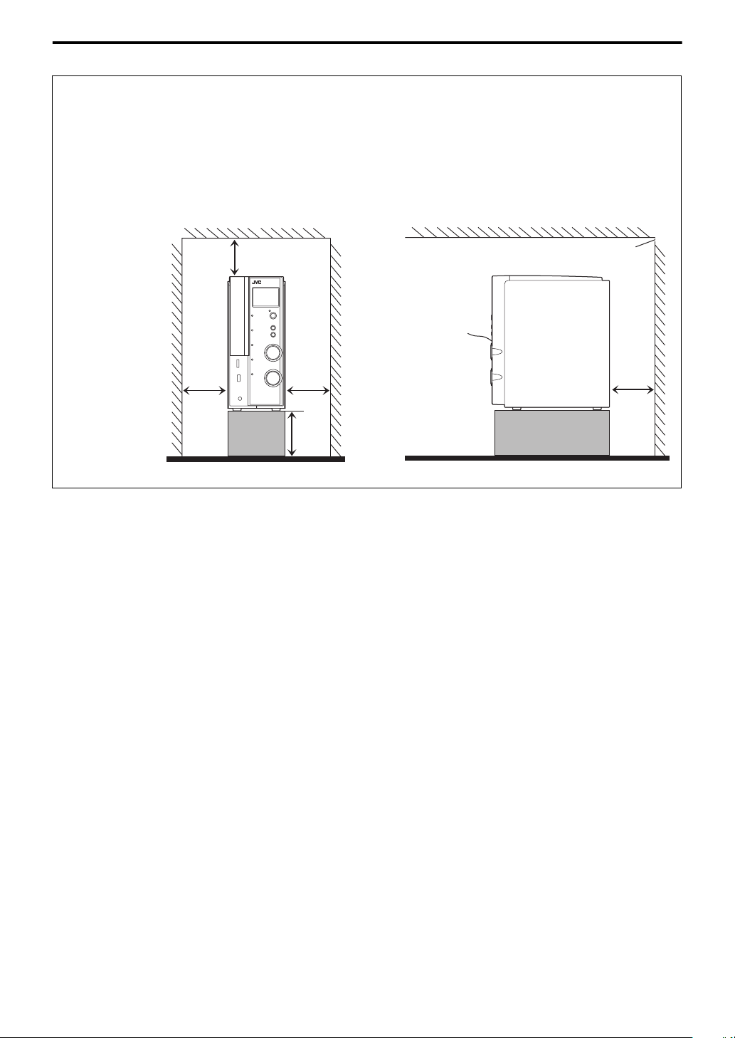
Index of parts and controls
The numbers in the figures indicate the pages where the details of the parts are described.
Front panel (center unit)
Display window
12
12
18
28
27 17
19
26
22
16
12
12
13
13
17
16
16
17
16, 20, 22, 25
20, 23
22
20, 23
Remote sensor: 6
16
4
Page 9
Index of parts and controls
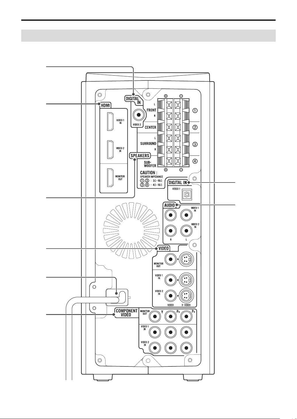
Rear panel (center unit)
11
9, 10, 11
9, 10, 11
13
9, 10, 11
10
7
10, 11
5
Page 10
Index of parts and controls
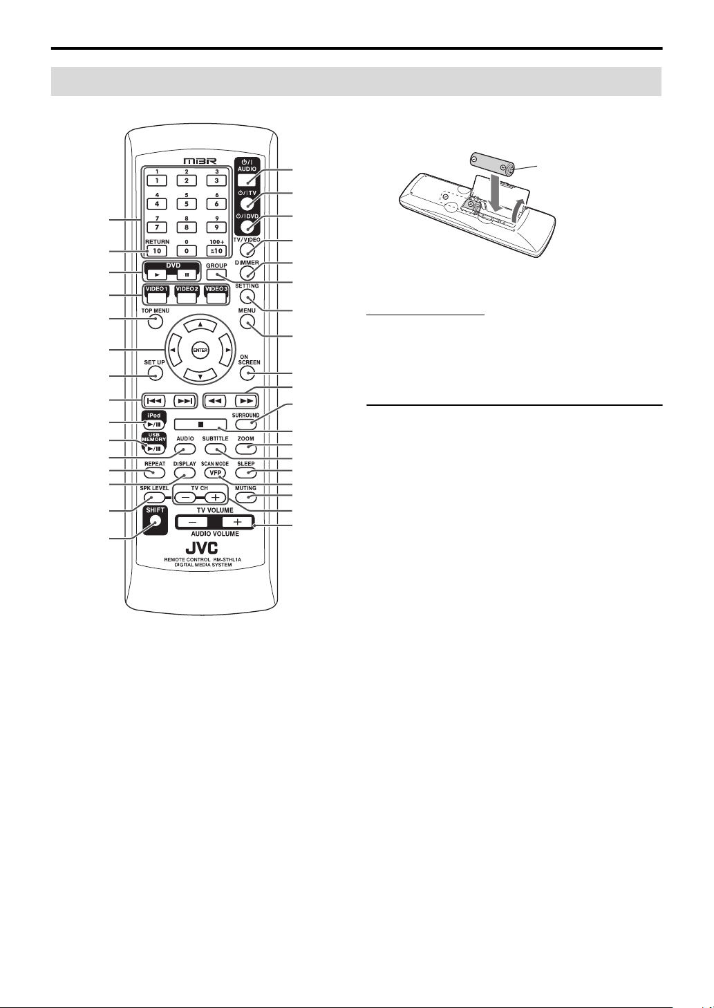
Remote control
7 Putting batteries in the remote control
Number
buttons:
14, 15, 23
14
15
16
15
14, 15, 18,
24, 25,
29 – 31
29
15, 20,
23, 24
16, 20
16, 22 – 25
15
26
22
18
14, 15
16
14
15
14
17
23
31
15
24
15, 23
28
15, 20, 22,
25
15, 25
15
17
18, 25
17
14, 18
14, 17
R6 (SUM-3)/AA (15F)
type dry-cell batteries
(supplied)
If the range or effectiveness of the remote control decreases,
replace both batteries.
CAUTION
• Batteries shall not be exposed to excessive heat such as
sunshine, fire or the like.
Operating the system from the remote
control
Aim the remote control directly to the remote sensor of the
center unit.
• If you operate it from a diagonal position, the operating
range (approx. 5 m (16 ft)) may be shorter.
• Do not block the remote sensor.
6
Page 11
Connections
Do not connect the power cord until all other connections have been made.
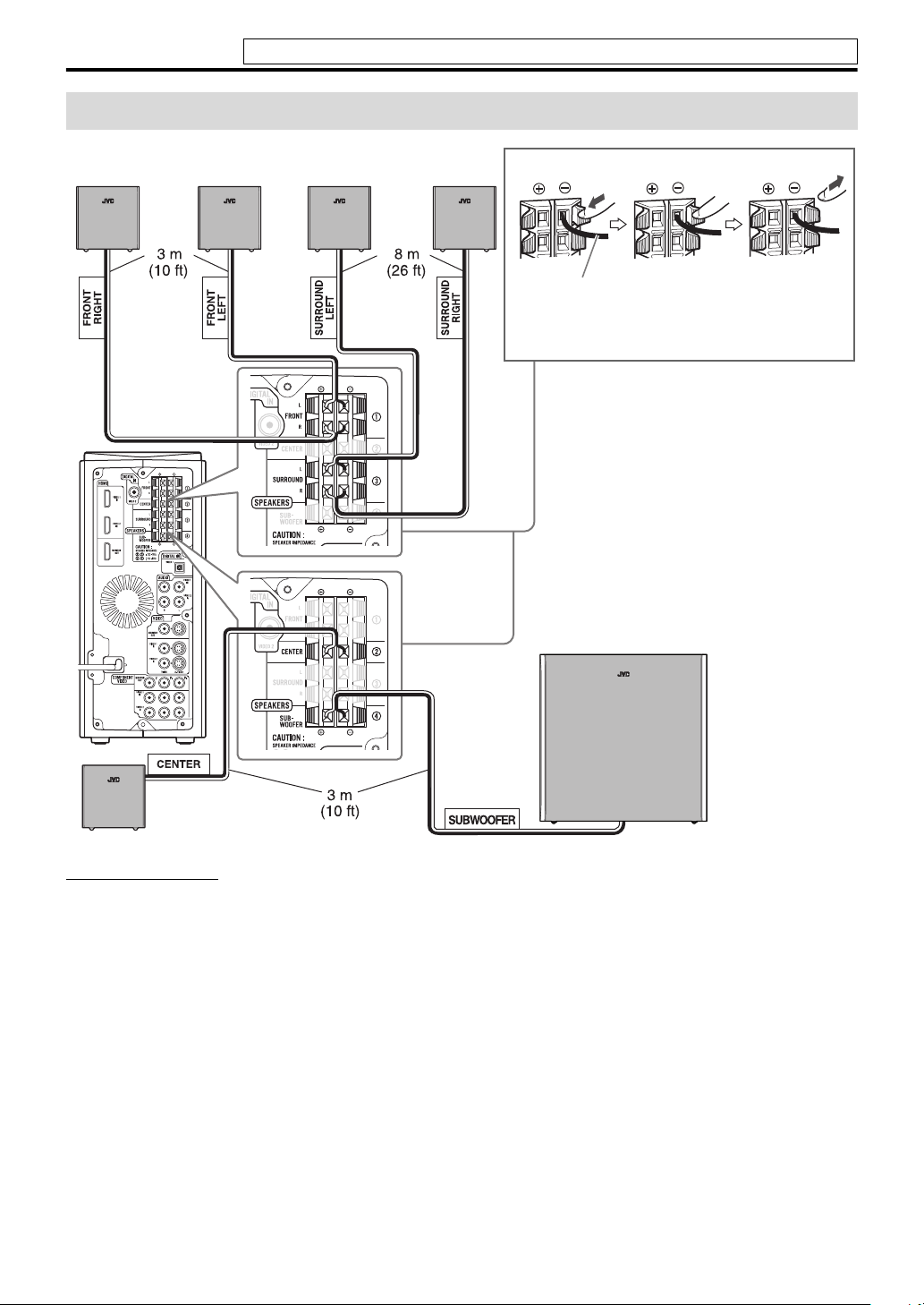
Connecting the speakers and subwoofer
SP-THL1F
Front speakers
SP-THL1S
Surround speakers
Speaker cord
• Connect the black cords to the black (–) terminals.
• Connect the white cords to the red (+) terminals.
SP-THL1W
Subwoofer
SP-THL1C
Center speaker
CAUTION
• If you connect speakers other than the supplied ones, use speakers of the same speaker impedance (SPEAKER IMPEDANCE)
indicated on the rear of the center unit.
• DO NOT connect more than one speaker to one speaker terminal.
• When installing the satellite speakers on the wall;
– Be sure to have them installed on the wall by qualified personnel.
DO NOT install the satellite speakers on the wall by yourself to avoid unexpected damage from falling off the wall due to
incorrect installation or weakness in wall structure.
– Care must be taken in selecting a location for speaker installation on a wall. Injury to personnel or damage to equipment may
result if the speakers installed interfere with daily activities.
Precautions for daily use
• When moving the speakers, do not pull the speaker cords; otherwise, the speakers may fall over, causing damage or injury.
• Do not reproduce sounds at so high a volume that the sound is distorted; otherwise, the speakers may be damaged by
internal heat buildup.
7
Page 12
Connections
Do not connect the power cord until all other connections have been made.
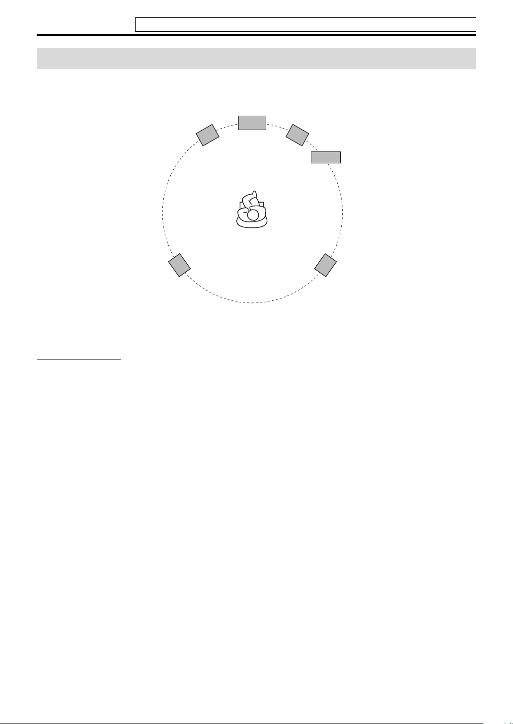
Speaker layout
To obtain the best possible sound from this system, you need to place all the speakers except the subwoofer at the same
distance from the listening position.
Front left
Center speaker
speaker
Surround left
speaker
If your speakers cannot be placed at the same distance from the listening position
You can adjust the delay time of the speakers. See “Delay menu (DELAY)” on page 30.
NOTE
• Place the satellite speakers on a flat and level surface.
• The subwoofer, front and center speakers are magnetically shielded to avoid color distortions on TVs. However, if not installed
properly, they may cause color distortions. So, pay attention to the following when installing the speakers.
– When placing the speakers near a TV set, turn off the TV’s main power switch or unplug it before installing the speakers. Then
wait at least 30 minutes before turning on the TV’s main power switch again.
Some TVs may still be affected even though you have followed the above. If this happens, move the speakers away from the TV.
• The surround speakers are not magnetically shielded.
If they are located nearby the TV or monitor, it will probably cause color distortion on the screen. To avoid this, do not place the
speakers nearby the TV or monitor.
Front right
speaker
Subwoofer
Surround right
speaker
8
Page 13

Connections
Do not connect the power cord until all other connections have been made.
Connecting a TV
• You can get better picture quality in the order — HDMI > Component video > S-video > Composite video.
• Distortion of picture may occur when connecting the TV via a VCR, or to a TV with a built-in VCR.
• You need to set “MONITOR TYPE” in the PICTURE menu correctly according to the aspect ratio of your TV. (See page
29.)
• If your TV supports progressive video input, you can enjoy a high quality picture from the source of “USB MEMORY” by
setting the progressive scan mode to active and connect your TV with the HDMI cord or component video cord. (See
page 18.)
• You can use below terminals for each sources to see the picture on the TV.
Ter mi na l
HDMI
COMPONENT VIDEO
S-VIDEO √√√√
VIDEO √
Source
VIDEO 1
VIDEO 2
√ —
√
VIDEO 3 iPod
——
—
√√√
To HDMI input
—
USB
MEMORY
√
TV
To composite
video input
To component
video input
Center unit
HDMI cord (not supplied)
Align the
marks.
5
S-video cord
(not supplied)
or
Composite video cord
(supplied)
Component video cord
To S-video
input
(not supplied)
NOTE
• HDMI MONITOR OUT terminal passes through the signal from the HDMI input terminal (VIDEO 1 and VIDEO 2) selected as
the source.
• COMPONENT MONITOR OUT terminal passes through the signal from the COMPONENT input terminal (VIDEO 1 and
VIDEO 2) selected as the source.
• S-VIDEO MONITOR OUT terminal passes through the signal from the S-VIDEO input terminal (VIDEO 1, VIDEO 2 and
VIDEO 3) selected as the source.
• VIDEO MONITOR OUT terminal passes through the signal from the VIDEO input terminal (VIDEO 1, VIDEO 2 and VIDEO
3) selected as the source.
• Use an HDMI cable shorter than 5 m (15 ft).
• When you are playing HDCP (High-Bandwidth Digital Content Protection) content, the sound and picture may not be
transmitted to the speakers and TV for a few seconds at the beginning due to the confirmation process.
• If the component video input jacks of your TV are of the BNC type, use a plug adapter (not supplied) to convert the pin plugs to
BNC plugs.
9
Page 14

Connections
Do not connect the power cord until all other connections have been made.
Connecting the video components for the source of VIDEO 1
7 To connect the video components for the source of VIDEO 1
• You can get better picture quality in the order — HDMI > Component video > S-video > Composite video.
Center unit
Digital optical audio cord
(not supplied)
RCA pin plug cord
(not supplied)
Align the
marks.
Composite video cord (supplied)
HDMI cord (not supplied)
To digital optical
audio output
To analog
audio output
5
S-video cord
(not supplied)
To S-video
output
or
Component video cord
DVD recorder, DVD player,
(not supplied)
To HDMI output
satellite tuner, VCR
or game console
To composite
video output
To component
video output
NOTE
• Unify the way of TV connection and that of video component’s (for example, connect a video component through S-VIDEO jack
when TV is connected through S-VIDEO jack). Otherwise, the signal from the component is not sent to the TV.
• The audio signal through the HDMI VIDEO 1 IN terminal is not reproduced on this system. The signal is reproduced on the TV
connected with HDMI MONITOR OUT terminal.
• Use an HDMI cable shorter than 5 m (15 ft).
• When you are playing HDCP (High-Bandwidth Digital Content Protection) content, the sound and picture may not be
transmitted to the speakers and TV for a few seconds at the beginning due to the confirmation process.
• If the component video output jacks of your video components of the BNC type, use a plug adapter (not supplied) to convert the
pin plugs to BNC plugs.
• When shipped from the factory, the source of “VIDEO 1” have been set for use with the AUDIO VIDEO 1 IN terminal for the
audio connection. If you connect the components with digital optical audio cord, change the audio input (VIDEO 1) setting to
“Digital.” (See page 31.)
• Before connecting a digital optical cable, unplug the protective plug from DIGITAL IN VIDEO 1 terminal.
• If you connect a sound-enhancing device such as a graphic equalizer between the source components and this system, the sound
output through this system may be distorted.
10
Page 15

Connections
Do not connect the power cord until all other connections have been made.
Connecting the video components for the source of VIDEO 2
7 To connect the video components for the source of VIDEO 2
• You can get better picture quality in the order — HDMI > Component video > S-video > Composite video.
Digital coaxial audio cord (not supplied)
Center unit
HDMI cord
(not supplied)
RCA pin plug cord
(not supplied)
Composite video cord
(supplied)
Align the
5 marks.
To HDMI output
To analog
audio output
To composite
video output
or
S-video cord (not supplied)
DVD recorder, DVD player,
Component video cord
satellite tuner, VCR
or game console
To S-video
output
(not supplied)
To digital coaxial
audio output
To component
video output
NOTE
• Unify the way of TV connection and that of video component’s (for example, connect a video component through S-VIDEO jack
when TV is connected through S-VIDEO jack). Otherwise, the signal from the component is not sent to the TV.
• The audio signal through the HDMI VIDEO 2 IN terminal is not reproduced on this system. The signal is reproduced on the TV
connected with HDMI MONITOR OUT terminal.
• Use an HDMI cable shorter than 5 m (15 ft).
• When you are playing HDCP (High-Bandwidth Digital Content Protection) content, the sound and picture may not be
transmitted to the speakers and TV for a few seconds at the beginning due to the confirmation process.
• If the component video output jacks of your video components of the BNC type, use a plug adapter (not supplied) to convert the
pin plugs to BNC plugs.
• When shipped from the factory, the source of “VIDEO 2” have been set for use with the AUDIO VIDEO 2 IN terminal for the
audio connection. If you connect the components with digital coaxial audio cord, change the audio input (VIDEO 2) setting to
“Digital.” (See page 31.)
• If you connect a sound-enhancing device such as a graphic equalizer between the source components and this system, the sound
output through this system may be distorted.
11
Page 16

Connections
Do not connect the power cord until all other connections have been made.
Connecting the video components for the source of VIDEO 3
7 To connect the video components for the source of VIDEO 3
• You can get better picture quality in the order — S-video > Composite video.
Center unit
Digital optical audio cord
(not supplied)
Align the
RCA pin plug
cord
(not supplied)
NOTE
• Unify the way of TV connection and that of video component’s (for example, connect a video component through S-VIDEO jack
when TV is connected through S-VIDEO jack). Otherwise, the signal from the component is not sent to the TV.
• When playback from USB source, scan mode can be adjusted to have better picture quality. (See page 18.)
• If you connect a sound-enhancing device such as a graphic equalizer between the source components and this system, the sound
output through this system may be distorted.
• When shipped from the factory, the source of “VIDEO 3” have been set for use with the VIDEO 3 AUDIO L/R audio terminal
for the audio connection. If you connect the components with digital optical audio cord, change the audio input (VIDEO 3)
setting to “Digital.” (See page 31.)
5 marks.
To analog audio output
S-video cord (not supplied)
or
Composite video cord
(supplied)
To composite
video output
game console or
camcorder
To S-video
output
To digital optical audio
output
12
Page 17

Connections
Do not connect the power cord until all other connections have been made.
Connecting a USB mass storage class device
You can connect a USB mass storage class device such as a
USB flash memory device, hard disk drive, multimedia card
reader, digital camera, etc. to this system.
• After connecting a USB mass storage class device to this
system and selecting USB MEMORY as the source, the
file control display appears on the TV screen. (See page
24.)
Center unit (on the front panel)
USB cable (not supplied)
NOTE
• Connect one USB mass storage class device to the system at a
time. Do not use a USB hub.
• While playing back a file in a USB mass storage class device,
do not disconnect the device. It may cause a malfunction of
both the system and the device.
• JVC bears no responsibility for any loss of data in the USB
mass storage class device while using this system.
• When connecting with a USB cable, use a cable less than 1 m
(3.3 ft) in length.
• This system is compatible with USB 2.0 Full Speed.
• You can play back the following types of files in a USB mass
storage class device (maximum data transfer rate: 2 Mbps):
–Music: MP3, WMA, WAV
–Picture : JPEG
– Movie : MPEG-1, MPEG-2, ASF
• To view a picture/movie files in a USB mass storage class
device on the TV, connect the system to the TV via the
composite, S-video or component jacks.
• You cannot play back a file larger than 2 GB.
• When playing a file which has a large transfer rate, frames or
sounds may be dropped during playback.
• This system cannot recognize a USB mass storage class
device whose rating exceeds 5 V/500 mA.
• This system may not recognize some USB mass storage class
devices and does not support DRM (Digital Rights
Management).
• This system may not play back some files even though their
formats are listed above.
• The battery of a USB mass storage class device is charged
while “USB MEMORY” is selected as the source.
• You cannot connect a computer to the (USB MEMORY)
terminal of the system.
• When connecting a USB mass storage device, refer also to its
manual.
• An iPod does not play on the USB MEMORY terminal.
(See page 9.)
Connecting the iPod
Center unit (on the front panel)
Turn the arrow-mark
side left when
connecting the plug.
Connection cable for iPod
(supplied)
Stand for iPod (supplied)
CAUTION
• Be sure to reduce the volume on the system to the minimum
level before connecting an iPod. Adjust the volume after
playback has started.
• DO NOT connect or disconnect the iPod when the system is
turned on.
NOTE
• To disconnect the connection cable from the iPod, hold the
buttons on the sides of the plug then pull it out.
• You cannot send any data to your iPod from the system.
• Do not carry the System with iPod connected. You might
drop it or it might cause damages to the connector part.
• Do not touch or hit the iPod terminal pins or connector pins
directly. It might cause damages to the connector part.
• “iPod” indicator lights up during iPod connectivity.
• T o view a video/picture from the iPod on the TV, connect the
system to the TV via the composite or S-video jacks.
(See
page 9.)
• iPod does not correspond to the component video output.
Connecting the power cord
Center unit
Plug into an AC outlet.
Power cord
CAUTION
• Disconnect the power cord before cleaning or moving the
system.
• Do not pull on the power cord to unplug the cord. When
unplugging the cord, always grasp and pull the plug so as not
to damage the cord.
NOTE
• If the wall outlet does not match the AC plug, use an AC plug
adapter (not supplied).
13
Page 18

Operating the TV and DVD player
You can use the remote control to operate not only this unit but also JVC and other manufacturers’ TV and DVD
player.
• Refer also to the manuals supplied for the TV and DVD player.
• To operate the equipment, aim the remote control directly at the remote sensor on the target equipment.
The buttons described below are used on pages 14 to
15.
Number
buttons
3 Press number buttons (1 - 9, 0) to
enter the manufacturer’s code (2
digits).
Examples:
For a AKAI TV: Press 0, then 2.
For a FISHER TV: Press 1, then 7.
* 01 is the initial setting.
JVC 01* PHILIPS 29
AKAI 02, 17 PIONEER 42
DAEWOO 08, 09, 29 SABA
FISHER 17 SAMSUNG
HITACHI 24, 26 SANYO 17
IRRADIO 17 SCHNEIDER 17
MAGNAVOX 29 SHARP 54
MARANTZ 30 SONY 55
MITSUBISHI 30 TOSHIBA 53
ORION 38 ZENITH 69, 70
PANASONIC 39, 41
35, 36, 37,
62, 63, 64
29, 51, 52,
71, 72, 73,
74
4 Release TV.
If there is more than one code listed for corresponding
brand, try each one until you enter the correct one.
NOTE
• Manufacturers’ codes are subject to change without notice.
Operating the TV
7 To set the manufacturer’s code
1 Press and hold TV.
Press and hold the button until step 3 is finished.
2 Press ENTER.
14
7 To operate a TV
You can perform the following operations on the TV.
TV Turn on or off the TV.
TV/VIDEO Set the input mode (either
TV or VIDEO).
1 - 9, 0, or +100 while
pressing SHIFT
RETURN while pressing
SHIFT
TV CH +/– while pressing
SHIFT
TV VOLUME +/– while
pressing SHIFT
NOTE
• The operating buttons may differ depending on
manufacturers.
Selects the channels.
Alternates between the
previously selected channel
and the current channel.
Change the channels.
Adjust the volume.
Page 19

Operating the TV and DVD player
Operating the DVD player
7 To set the manufacturer’s code
1 Press and hold DVD.
Press and hold the button until step 3 is finished.
2 Press ENTER.
3 Press number buttons (1 - 9, 0) to
enter the manufacturer’s code (2
digits).
Examples:
For a MAGNAVOX DVD player: Press 0, then 5.
For a PANASONIC DVD player: Press 1, then 0.
* 01 is the initial setting.
JVC 01* PIONEER 11
KENWOOD 03, 04 PROSCAN 12
MAGNAVOX 05 RCA 12
MARANTZ 06 SAMSUNG 13
MITSUBISHI 07 SONY 14
ONKYO 08, 09 TOSHIBA 05
PANASONIC 10 YAMAHA 15
PHILIPS 06 ZENITH 05, 16
4 Release DVD.
If there is more than one code listed for corresponding
brand, try each one until you enter the correct one.
See page 14 for button locations.
7 To operate a DVD player
You can perform the following operations on the DVD
player.
DVD Turn on or off the DVD
player.
DVD 3 Play back a disc.
DVD 8 Pause playback. To release
it, press DVD 3.
1 - 9, 0 while pressing
SHIFT
TOP MENU Display a DVD top menu.
MENU Display a DVD menu.
2 / 3 / 5 / K Select a DVD menu item.
ENTER Enter a DVD menu item.
4 / x Skip to the beginning of
1 / y Fast-forward/fast-reverse
7 Stop playback.
AUDIO Select the audio language/
SUBTITLE Select the subtitle language.
ZOOM Enlarge the picture.
NOTE
• The operating buttons may differ depending on
manufacturers.
Select a desired chapter
number.
next chapter / return to the
beginning of current (or
previous) chapter.
search.
audio channel.
15
Page 20

Basic operations
The buttons on the remote control are used to explain
most of the operations in this manual. You can use the
buttons on the center unit if they have the same name or
marks as on the remote control, unless otherwise noted.
• The icon such as shows the file types the operation is
available for.
The buttons described below are used on pages 16 to
18.
Turning the system on/off
On the remote control:
Press AUDIO.
On the center unit:
Press .
NOTE
• A small amount of power is consumed even when the power
is turned off. This is called standby mode and the STANDBY
lamp lights in this mode. Unplug the power cord from the
AC outlet to turn the power off completely.
• You can also turn on the system by pressing the following
buttons;
– One of the source selecting buttons on the remote control
(VIDEO1, VIDEO2, VIDEO3, iPod
MEMORY
– iPod/USB MEMORY CONTROL ‹/8 on the center unit.
(Turning on by the button automatically changes the
source to USB MEMORY except when the last source was
iPod.)
6)
6 and USB
Selecting the source to play
On the remote control:
Press one of the source selecting
buttons (VIDEO1 - 3,
USB MEMORY 6, or iPod 6).
USB MEMORY 6: To play back a file in a USB mass
storage class device. (See page 21.)
iPod 6: To start play back a connected iPod. (See page
19.)
VIDEO1 - 3: To select the external components connected to
the VIDEO 1 - 3 terminals on the center unit. (See page 10
to 12.)
On the center unit:
Press INPUT SELECTOR 9 / 8
repeatedly until the source name you
want appears on the display window.
NOTE
• The source selection lamp of the selected source lights up on
the center unit.
• It may take time to change the source.
16
Page 21

Basic operations
See page 16 for button locations.
Adjusting the volume [VOLUME]
CAUTION
• Always set the volume to minimum level before starting any
source. If the volume is set at a high level, the sudden blast of
sound may damage your hearing and/or blow out the
speakers.
On the remote control:
Press AUDIO VOLUME +/–.
On the center unit:
Press VOLUME +/–.
Listening with headphones (not supplied)
CAUTION
Be sure to turn down the volume;
• Before connecting or putting on headphones as high volume
may damage both the headphones and your hearing.
• Before disconnecting headphones as high volume may
suddenly come out of the speakers.
While connecting a pair of headphones to the PHONES
jack on the center unit, the system automatically cancels the
surround mode (see page 27) currently selected, deactivates
the speakers, and activates the headphone mode. “HEAD
PHONE” appears on the display window.
Headphone mode
When using the headphones, the following signals come out
regardless of your speaker setting;
• For 2 channel sources, the front left and right channel
signals are come out from the headphones.
• Multi-channel signals are downmixed and come out from
the headphones.
Turning off the sound temporarily [MUTING]
Adjusting the brightness of the indications [DIMMER]
Press DIMMER.
Each time you press the button, you can change the
brightness level in 3 steps.
Sleep Timer [SLEEP]
The system turns off automatically when the specified
period of time has passed.
Press SLEEP repeatedly.
Each time you press the button, the shut-off time changes as
follows:
10 Z 20 Z 30 Z 60 Z 90 Z 120 Z 150 Z 180 Z
– – (Canceled) Z (back to the beginning)
•The SLEEP indicator lights up on the display.
Example:
SLEEP indicator
shut-off time
To check the remaining time
Press SLEEP once.
To change the remaining time
Press SLEEP repeatedly.
To cancel
Press
SLEEP
repeatedly, until “SLEEP
•The SLEEP indicator goes off.
• Turning off the power also cancels the Sleep Timer.
– –
” appears.
Press MUTING.
To restore the sound
Perform one of the following:
• Press MUTING again.
• Press AUDIO VOLUME +/–.
• Press VOLUME +/– on the center unit.
17
Page 22

Basic operations
See page 16 for button locations.
Adjusting the output level of the speakers and subwoofer
1 Press SPK LEVEL to show the
target speaker indication on the
display window.
Each time you press the button, the indication of the
speakers changes as follows:
FRNT L (Front left speaker) Z FRNT R (Front right
speaker) Z CENTER (Center speaker) Z SURR L
(Surround left speaker) Z SURR R (Surround right
speaker) Z SUBWFR (Subwoofer) Z (back to the
beginning)
2 Press +/– to adjust the output
level from –6 to +6 while speaker
indication is displayed.
NOTE
• You can also make adjustments by using the setup menu
shown on the TV screen. (See page 30.)
• The adjustments take effect for all sources.
Changing the scanning mode
The system can be accommodated to your TV’s
scanning mode when playing back a JPEG/
MPEG-1/MPEG-2/ASF file in the USB mass
storage class device.
NOTE
• To use the system in the progressive mode, it is required that
the center unit is connected to the TV by using component
video cord (not supplied). (See page 9.)
7While USB MEMORY playback is stopped
1 Press and hold SCAN MODE for 2
seconds.
The current setting appears on the display window.
2 Press 2/3 to select the desired
mode.
• INT-LACE: Select when your TV supports the
interlaced scanning mode only.
• PROGRESS: Select when your TV equipped with
component jacks terminal supports the progressive
scanning mode.
You can get better picture quality in PROGRESS mode
than in INT-LACE mode.
3 Press ENTER while the selected
mode is displayed.
When “PROGRESS” is selected, the PROGRESSIVE
indicator lights on the display window.
NOTE
• Although the picture may be distorted when you press
ENTER, this is not a malfunction of the system.
• There are some progressive TVs and HighDefinition TVs that are not fully compatible with
this system, resulting in an unnatural picture when
playing back a JPEG/MPEG-1/MPEG-2/ASF file in
the progressive scanning mode. In such a case,
change the scanning mode to “INT-LACE.”
• All JVC progressive TVs and High-Definition TVs
are fully compatible with this system.
18
Page 23

Operations for iPod
*
The buttons described below are used on page 20.
Playing an iPod
CAUTION
• Before selecting the video source to play, make the
appropriate setting for video output on the iPod.
Compatible iPod types:
iPod model
iPod nano 1GB/2GB/4GB
iPod nano (2nd Generation)
2GB/4GB/8GB
iPod mini 4GB/6GB
iPod (4th Generation) 20GB/40GB
iPod photo (4th Generation)
20GB/30GB/40GB/60GB
iPod video (5th Generation)
30GB/60GB/80GB
*2Only for still picture.
• If the iPod does not play correctly, update your iPod Software
to the latest version. For details about updating your iPod,
check on the Apple web site <http://www.apple.com>.
• If incompatible iPod type is connected, the iPod may not be
operated from the System. To enable the operation, before
connecting the iPod, switch the charge mode to
OFF
”
( refer to “To turn ON/OFF the charge mode” on page
20) with
“
iPod” selected as source.
NOTE
• Sound distortion may occur when playing back audio
sources with high recording levels. When distortion occurs,
it is recommended to turn off the equalizer of the iPod. For
information on operating the iPod, see the iPod instruction
manual.
AUD IO VI DEO
√
√
√
√
“
CHARGE
2
√√*
√√
1
This button does not function as a stop button to operate
an iPod. This button functions only to turn ON/OFF the
charge mode to operate an iPod.
19
Page 24

Operations for iPod
See page 19 for button locations.
To turn ON/OFF the charge mode
7While “iPod” is selected as a source
1 Display the current charge mode.
On the remote control:
Press and hold 7 for 2 seconds.
On the center unit:
Press and hold iPod/USB MEMORY
CONTROL 7 for 2 seconds.
The current charge mode appears on the display
window.
2 Select the desired charge mode.
On the remote control:
Press 7 repeatedly.
On the center unit:
Press iPod/USB MEMORY
CONTROL 7 repeatedly.
• CHARGE ON: Select when you want to charge the
iPod battery through the iPod terminal.
• CHARGE OFF: Select when you do not want to
charge the iPod battery through the iPod terminal.
NOTE
• When the charge mode is “CHARGE ON” the iPod battery is
charged through the iPod terminal while “iPod
.
a source
• The initial setting of charge mode is
advisable to set it to “CHARGE ON” for most of the time.
“
CHARGE ON” and it is
Starting playback
” is selected as
To pause playback
On the remote control:
Press iPod 6 during playback.
On the center unit:
Press iPod/USB MEMORY CONTROL
‹/8 during playback.
To continue playback, press the button again.
Fast-forward/fast-reverse search
On the remote control:
Press and hold 4 or x during
playback.
On the center unit:
Press and hold iPod/USB MEMORY
CONTROL 4 or x during
playback.
To return to normal speed playback
Release the button.
Skip to the next/previous item
On the remote control:
Press 4 or x.
On the center unit:
Press iPod/USB MEMORY CONTROL
4 or x.
1 Connect an iPod (see page 13)
while the system is turned off.
2 Turn on the system. (see page 16)
3 Select “iPod” as the source. (see
page 16)
“iPod CONNECT” appears on the display. If an iPod is
not connected firmly,
•The iPod indicator lights up on the display.
“iPod NO CONNECT” appears.
4 Start playing on the iPod.
On the remote control:
Press iPod 6.
On the center unit:
Press iPod/USB MEMORY
CONTROL ‹/8.
Press above button again if iPod does not start
playback.
20
Turning off the iPod
On the remote control:
Press and hold iPod 6.
On the center unit:
Press and hold iPod/USB MEMORY
CONTROL ‹/8.
Turning off the system (on standby mode) or selecting
another source also turns off the iPod.
Page 25

Operations for USB MEMORY
• The icon such as shows the file types the operation is
available for.
The buttons described below are used on pages 22 to
26.
Number
buttons
Basic operations for USB MEMORY
When “USB MEMORY” is selected as the source, the
following messages will appear on the TV screen.
• “NOW READING”:
Appears when the system is reading the file
information.
•“NO USB DEVICE”:
Appears when no USB mass storage class device is
connected.
• “CANNOT PLAY THIS DEVICE”:
Appears when unplayable USB mass storage class
device is connected or no supported file is stored.
CAUTION
• Always set volume to the minimum level when connecting
or disconnecting the other equipment.
• You cannot send any data to your USB mass storage class
device from this system.
21
Page 26
Operations for USB MEMORY
See page 21 for button locations.
Basic playback for USB MEMORY
7 To play a file in a USB mass storage class
device
1 Connect a USB mass
storage class device (see page 13)
while the system is turned off.
2 Turn on the system. (see page 16)
3 Select “USB MEMORY” as the
source. (see page 16)
4 Start playback.
On the remote control:
Press USB MEMORY 6.
On the center unit:
Press iPod/USB MEMORY
CONTROL ‹/8.
The operations of the files in a USB mass storage class
device depend on the file types stored in the device.
For MP3/WMA/WAV files
The file control display (see page 24) appears on the
TV screen.
For JPEG files
Each file (still pictures) is shown on the TV screen for
about 3 seconds (slide-show). When stop the playback,
the file control display (see page 24) appears on the TV
screen.
For MPEG-1/MPEG-2/ASF files
Pressing TOP MENU or MENU shows the file control
display (see page 24) on the TV screen during
playback.
NOTE
• When several types of files are recorded on a device, select file
type you want to play on the setup menu. (see page 30)
7 To stop
Press 7.
7 To pause
On the remote control:
Press USB MEMORY 6 during
playback.
On the center unit:
Press iPod/USB MEMORY CONTROL
‹/8 during playback.
To continue playback, press the button again.
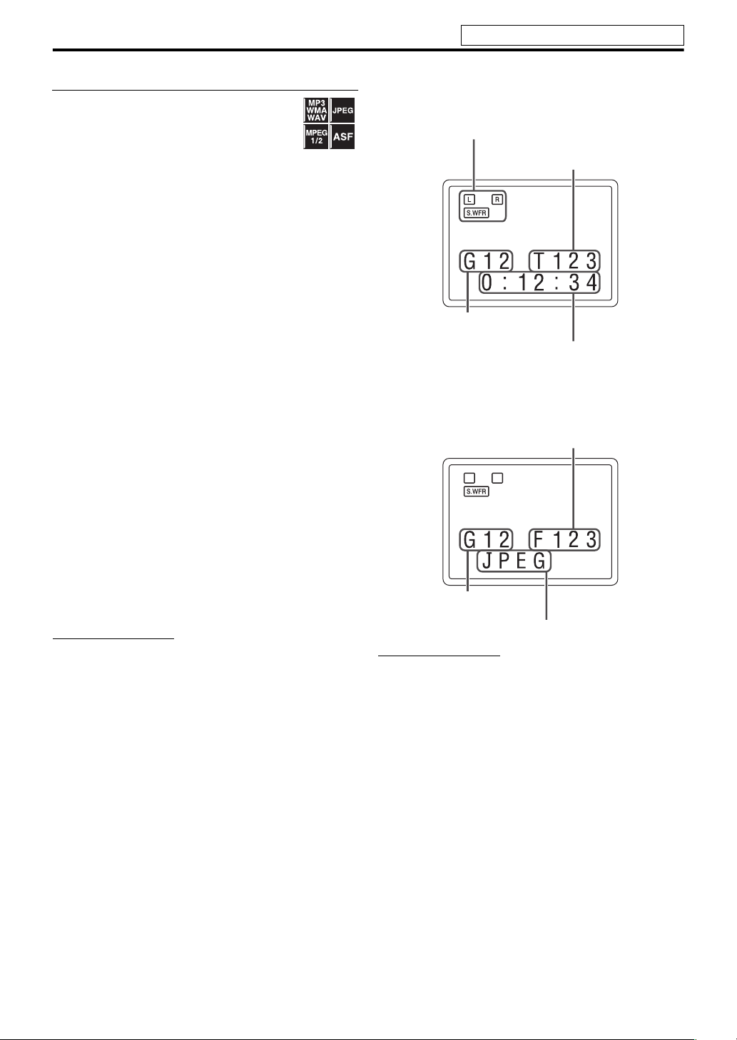
7 Playback information on the display window
MP3/WMA/WAV/MPEG-1/MPEG-2/ASF file
Example: When an MP3 file is played back
Signal and speaker indicators (see page 28)
File number
Group number
Elapsed playing time (hour:minute:second)
(during playback only)*
* Each time you press DISPLAY, the elapsed playing time
and the file information appears alternately.
JPEG file
File number
Group number
File type
NOTE
• You can also check the playback information using the onscreen bar. (See page 24.)
• When playback is stopped, the file type is shown on the
display window instead of elapsed playing time.
7 Screen saver
An image may burn in on a TV screen if a static picture is
displayed for a long time. To prevent this, the system
automatically dims the screen if a static picture is displayed
for over 5 minutes (the screen saver function).
• Pressing any button will cancel the screen saver function.
• If you do not want to use the screen saver function, see
page 29.
22
Page 27

Operations for USB MEMORY
See page 21 for button locations.
Fast-forward/fast-reverse search
Press 1 or y during
playback.
Each time you press the button, the search
speed changes (x2, x5, x10, x20, x60).
To return to normal speed playback
Press USB MEMORY 6 on the remote control.
NOTE
• When a MP3/WMA/WAV file is played back, sound is
intermittent and low during fast-forward/reverse search.
• This feature may not work for some files.
• For MP3/WMA/WAV file,
the search speed is not shown.
To skip files one by one
On the remote control:
Press 4 or x.
On the center unit:
Press iPod/USB MEMORY CONTROL
4 or x.
NOTE
• You can also make this operations using the file control
display. (See page 24.)
• This feature may not work for some files.
To select a file directly
Press number buttons (0-10,
h 10) to select the desired
number.
• For details on using the number buttons, see “How to use
the number buttons” below.
How to use the number buttons
To select 3: Press 3.
To select 10: Press 10.
To select 14: Press h 10, 1, then 4.
To select 24: Press h 10, 2, then 4.
To select 40: Press h 10, 4, then 0.
To select 114: Press h 10, h 10, 1, 1, then 4.
To locate a desired group
1 Press GROUP during
playback.
“– –” is shown in the group number area
(see page 22) on the display window.
2 While the display window shows
“– –”, use number buttons (0-10,
h 10) to enter the desired title or
group number.
The system starts playback from the first file of the
selected group.
• For details on using the number buttons, see “How to
use the number buttons” on the left column.
NOTE
• This feature may not work for some files.
On-screen guide icons
During MPEG-1/MPEG-2/ASF file playback,
the following guide icons may appear for a while
on the TV screen;
• (Play), (Pause), / (Fast
forward/fast-reverse): appears when you perform each
operation.
• : the file cannot accept an operation you have tried to
do.
NOTE
• To deactivate the on-screen guide icons, see page 31.
23
Page 28

Operations for USB MEMORY
See page 21 for button locations.
Advanced operations for USB MEMORY
Using the on-screen bar
You can check file information and use some
functions through the on-screen bar.
7 Showing the on-screen bar
Press ON SCREEN.
Each time you press the button, the on-screen bar changes
as follows on the TV screen.
Example: During ASF playback
OFF
(The on-screen bar disappears)
7 Contents of the on-screen bar during playback
1 Shows Repeat mode status. (See page 26.)
2 Shows time information.
3 Shows playback status.
: appears during playback.
/ : appears during fast forward/reverse.
: appears when paused.
: appears when stopped.
Using the file control display
You can search and play desired groups and
tracks/files using the file control display on the
TV screen.
Example:
Current group / total group number
(See page 26.)
Elapsed playing time of
Current track (file)
Current track (file)
Total track (file) number
Playback status
only)
Repeat mode
current track (except for JPEG)
Track information
(for MP3/WMA/WAV
Current group
Current track (file) / total track
(file) number on current group
The file control display appears automatically during
playback (for MP3/WMA/WAV only) or while stopped.
1 Press2/3/5/Y to select the
desired group/track/file while
playback is stopped.
2 Press USB MEMORY 6 or
ENTER.
• Track playback/slide-show starts from the selected
track/file.
• When you press ENTER for JPEG, only the selected
file is played back.
To skip the file during playback
Press x/4 or 5/Y.
NOTE
• You can also check playback information on the display
window. (See page 22.)
• Some group, track and file names may not be displayed
correctly depending on recording conditions.
• The order of groups, tracks, and files may be displayed
differently from the order displayed on your personal
computer.
24
Page 29
Operations for USB MEMORY
See page 21 for button locations.
Resuming playback
When Resume Playback is set to “ON” (see page
31) and you stop playback by the following
operations, the position where playback has
been stopped is stored. (
the display window.)
• Turning off the power (see page 16)
• Pressing 7 once
• Changing the source (see page 16)
To start playback from the stored position
• Press USB MEMORY 6 on the remote control or iPod/
USB MEMORY CONTROL ‹/8 on the center unit.
• Select
“USB MEMORY” as the source again if you
changed the source.
To clear the stored position
Press 7 again.
• Disconnecting the USB mass storage class device also
clears the stored position.
“RESUME” appears on
Zooming in
7During playback or while paused
1 Press ZOOM.
Each time you repeat the procedure, the
scene magnification changes.
2 While zoomed in, press 2/3/5/
Y to move zoom-in area.
To return to normal playback
Press ZOOM repeatedly, to select OFF.
NOTE
• The number of the magnification steps varies depending on
the file type.
• During slide-show playback of JPEG, zooming in is not
available. In such a case, press
slide-show playback, then zoom in.
•During playback,
2/3/5/Y may not work in step 2.
USB MEMORY 6 to pause
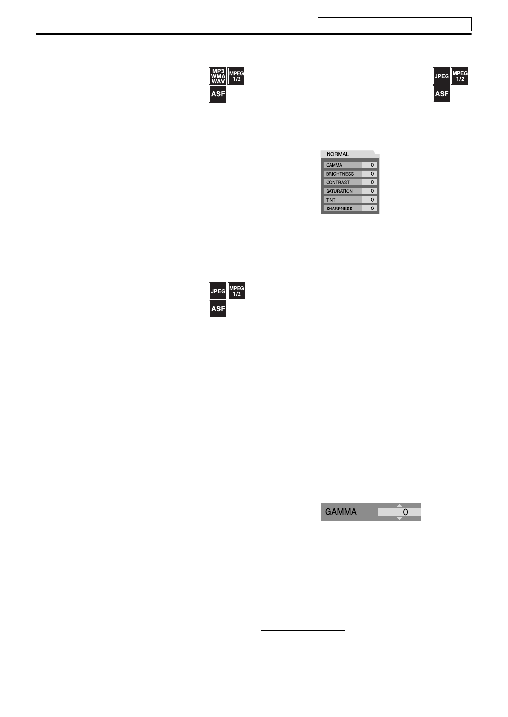
Changing the VFP setting
The VFP (Video Fine Processor) function
enables you to adjust the picture character
according to the type of programming, picture
tone or personal preference.
7During playback
1 Press VFP.
The current VFP settings appear on the TV screen.
Example:
2 Press 2/3 repeatedly to select
the VFP mode.
• NORMAL: Normally select this.
• CINEMA: Suitable for movies.
When you select “NORMAL” or “CINEMA,” press VFP
to complete the setting.
• USER 1 and USER 2: You can adjust parameters that
affect picture appearance.
Only when selecting “USER 1” or “USER 2” in step 2,
proceed to perform the following operation;
3 Press 5/Y repeatedly to select a
parameter you want to adjust.
Adjust gradually and confirm picture appearance
results are as preferred.
• GAMMA: Control brightness of neutral tints while
maintaining brightness of dark and bright portions
(–3 to +3).
• BRIGHTNESS: Control screen brightness (–8 to +8).
• CONTRAST: Control screen contrast (–7 to +7).
• SATURATION: C ontrol scre en c olor d ept h (–7 to
+7).
• TINT: Control screen tint (–7 to +7).
• SHARPNESS: Control screen sharpness (–8 to +8).
4 Press ENTER.
Example:
5 Press 5/Y to change the setting.
6 Press ENTER.
The current VFP settings appear again.
7 Repeat steps 3 to 6 to adjust other
parameters.
8 Press VFP.
NOTE
• If the setting display disappears in the middle of the
procedure, the setting at that time will be stored.
25
Page 30
Operations for USB MEMORY
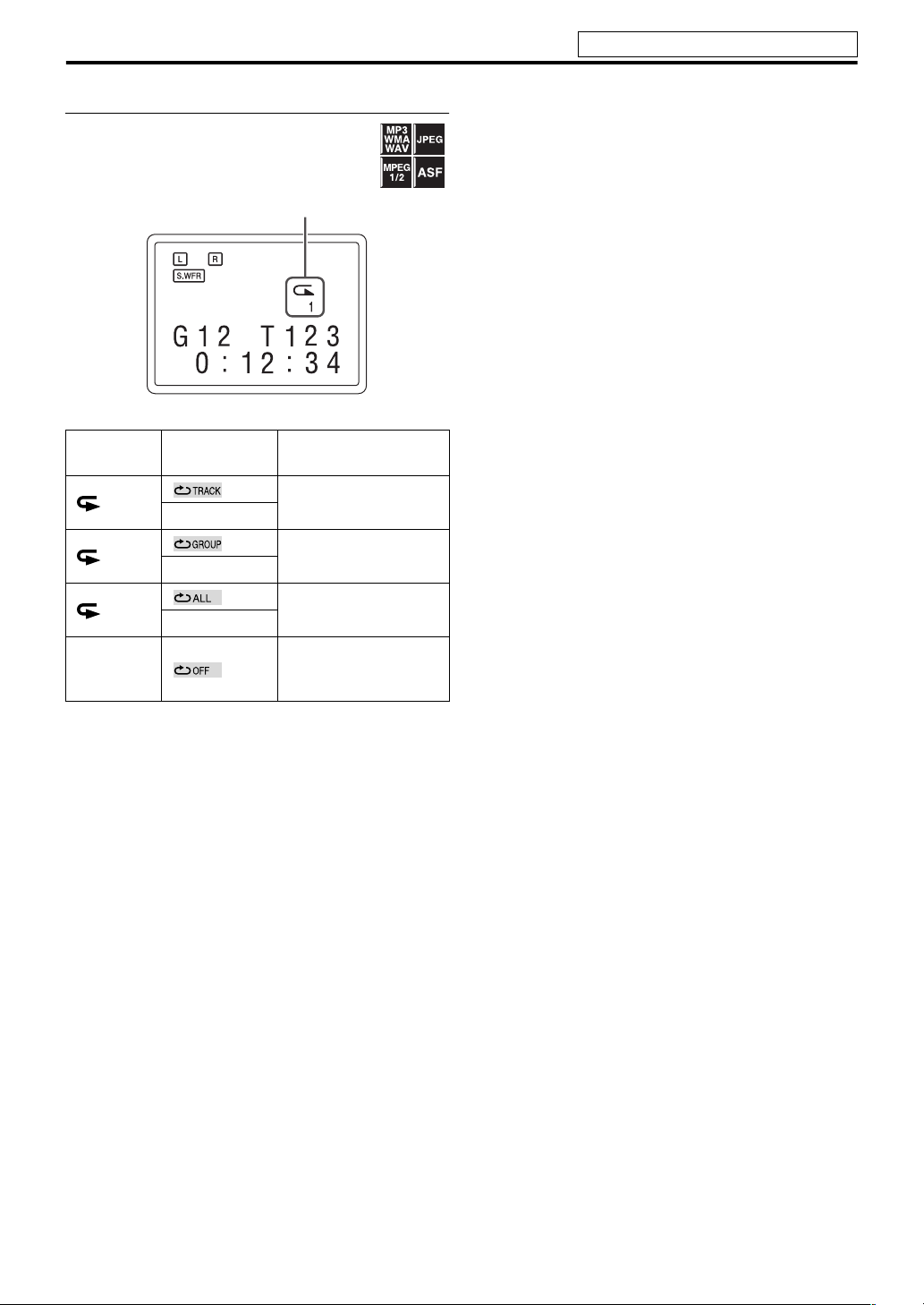
Repeating playback
When using the REPEAT button:
Press REPEAT.
Example:
Repeat mode indicator
Each time you press REPEAT, the Repeat mode changes.
See page 21 for button locations.
Display
window
1
ALL
No
indication
TV screen Meanings
Repeats the current
REPEAT TRACK
REPEAT GROUP
REPEAT ALL
track/files.
Repeats the current
group.
Repeats all tracks/files.
Repeat mode is off.
The system plays back
the file normally.
26
Page 31
Operations for surround mode
The buttons described below are used on page 28.
Using the surround mode
You can enjoy more realistic sound field than a stereo sound
by using the surround mode.
• The surround modes are also available for external
components.
7 Auto Surround (AUTO SURROUND)
This function automatically selects the appropriate
surround mode according to the incoming signals. For
example, a multi channel source is automatically
reproduced in an appropriate multichannel surround mode.
7 Dolby Surround
Dolby Pro Logic II*
Dolby Pro Logic II has a developed multichannel playback
format to decode all 2 channel sources — stereo source and
Dolby Surround encoded source — into a 5.1 channel.
Dolby Pro Logic II has 2 modes — Movie and Music:
• Pro Logic II Movie (DPL II MOVIE)
Suitable for reproduction of Dolby Surround encoded
sources bearing the mark .
• Pro Logic II Music (DPL II MUSIC)
Suitable for reproduction of any 2 channel stereo music
sources.
7 Dolby Digital*
Used to reproduce multichannel soundtracks of the
software encoded with Dolby Digital ( ).
• There are other encoding formats of digital surround
introduced by Dolby Laboratories, such as Dolby Digital
EX.
7 DTS Digital Surround*
Used to reproduce multichannel soundtracks of the
software encoded with DTS Digital Surround ( or
).
DTS Digital Surround (dts SURROUND) is another
discrete multi-channel digital audio format available on CD
and DVD software.
• There are other encoding formats of multi-channel
digital surround introduced by Digital Theater Systems,
Inc., such as DTS-ES, DTS 96/24.
1
1
2
Available Surround modes for each input signal
The √ marks show available surround modes.
Signal
Dolby Digital
(Multi-channel)
Dolby Digital
(2 channel)
DTS Digital Surround
(Multi-channel)
DTS Digital Surround
(2 channel)
Analog or Linear PCM
Mode Surround
off
SURROUND
OFF
√√—— √ ————
√√√√—— √√√
√√——— √ ———
√√√√—— √√√
√√√√—— √√√
Auto
Surround
AUTO
SURROUND
Dolby Surround
DPL II
MOVIE*
3
MUSIC*
DPL II
Dolby
Digital
DOLBY
3
DIGITAL
DTS Digital
Surround
dts
SURROUND
STADIUM
3
*
DSP
ALL CH
STEREO
3
*
GAME*
*1Manufactured under license from Dolby Laboratories. “Dolby”, “Pro Logic”, and the double-D symbol are trademarks of
Dolby Laboratories.
2
*
“DTS” and “DTS Digital Surround” are registered trademarks of DTS, Inc.
3
You can select these modes by pressing SURROUND. (See page 28.)
*
Continued on the next page
27
3
Page 32

Operations for surround mode
See page 27 for button locations.
7 DSP
• STADIUM
STADIUM mode adds clarity and spreads the sound, like in
an outdoor stadium.
• All Channel Stereo
All Channel Stereo (ALL CH STEREO) mode can
reproduce a larger stereo sound field using all the
connected (and activated) speakers.
All Channel Stereo can be used while reproducing 2
channel stereo source.
Normal stereo sound All Channel Stereo
•Game
The surround effect with the optimum force for a game.
7 Indicators on the display window
Digital signal format indicators
LPCM: Lights when Linear PCM signal comes in.
GD: Lights when Dolby Digital signals come in.
: Lights when DTS signals come in.
No indication: No digital signal indicator lights when
analog signals come in.
Dolby Surround mode indicator
GPLII: Lights when Dolby Pro Logic II is activated.
Surround indicator
SURR: Lights when the surround mode is activated.
Source signal indicators, etc.
Light to indicate the incoming signals.
: Lights when the front left channel signal
comes in.
: Lights when the center channel signal
comes in.
: Lights when the front right channel signal comes in.
: Lights when the LFE channel signal comes in.
: Lights when the surround left channel signal comes in.
: Lights when the surround right channel signal comes
in.
: Lights when the monaural surround channel signal or
2 channel Dolby Surround signal comes in.
: Always lights.
The channel with “ ” shows that the corresponding
speakers are reproducing the channels’ sound.
If the channels’ sound decoded into 5.1 channel is
reproduced, only “ ” lights.
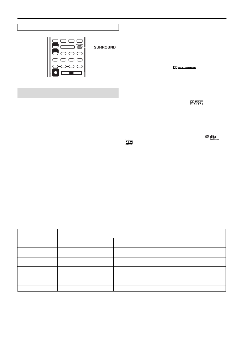
Selecting the surround mode
The system is set up to automatically select the optimal
surround mode for input signal from digital multichannel
software.
When playing back a 2 channel source, you can select the
desired surround mode manually.
7 When playing back digital multichannel software
(except while OFF is selected)
The appropriate multichannel surround mode (Dolby
Digital or DTS Digital Surround) is automatically selected.
7 When playing back a 2 channel source
You can select either Dolby Pro Logic II (DPL II MOVIE/
DPL II MUSIC) or the DSP mode.
Press SURROUND repeatedly to
select the desired mode.
The surround mode is turned on and the current surround
mode appears on the display window.
Each time you press the button, the surround mode
changes.
For details on each mode, see “Available Surround modes
for each input signal”. (See page 27.)
To turn off the surround mode
Press SURROUND repeatedly until
“SURROUND OFF” appears on the
display window.
Storing adjustments — auto memory
When you turn the power off, the system memorizes the
current surround mode. The memorized mode is
automatically recalled when you turn the power on.
NOTE
• During playback of MPEG-1, MPEG-2 or ASF files, the
surround mode setting is ineffective.
28
Page 33

Setting preferences
The buttons described below are used on page 29 to 31.
Using the setup menus
• You can change the language used in the setup menus.
See “Menu description” below.
NOTE
• You can use SET UP menu only when the source is USB
MEMORY.
Basic operation on the setup menus
: Picture menu (PICTURE)
7 MONITOR TYPE
You can select the monitor type to match your TV when
you play files recorded in the picture’s height/width ratio of
16:9.
• 16:9 NORMAL (Wide television screen)
Select this when the aspect ratio of your wide TV is fixed
to 16:9.
• 16:9 AUTO (Wide television conversion)
Select this when your TV is an ordinary wide TV.
• 4:3 LB (Letter Box conversion)
Select this when the aspect ratio of your TV is 4:3
(conventional TV). While viewing a wide screen picture,
the black bars appear on the top and the bottom of the
screen.
• 4:3 PS (Pan Scan conversion)
Select this when the aspect ratio of your TV is 4:3
(conventional TV). While viewing a wide screen picture,
the black bars do not appear, however, the left and right
edges of the pictures will not be shown on the screen.
Ex.: 16:9 Ex.: 4:3 LB Ex.: 4:3 PS
7While stopped
1 Press SET UP.
2 Follow the instructions that
appear on the TV screen.
Menu description
: Language menu (LANGUAGE)
7 ON SCREEN LANGUAGE
• Select the language shown on the TV screen when
operating this system.
NOTE
• Even if “4:3 PS” is selected, the screen size may become “4:3
LB” with some files. This depends on how files are recorded.
7 PICTURE SOURCE
You can obtain optimal picture quality by selecting whether
the content of the file is processed by field (video source) or
by frame (film source).
Normally set to “AUTO”.
•AUTO
Used to play a file containing both video and film source
materials.
This system recognizes the source type (video or film) of
the current file according to the file information.
–If the playback picture is unclear or noisy, or the oblique
lines of the picture are rough, try to change to fixed
modes.
•FILM
Suitable for playing back a film source file.
•VIDEO
Suitable for playing back a video source file.
7 SCREEN SAVER (See page 22.)
You can activate or deactivate screen saver function.
29
Page 34

Setting preferences
See page 29 for button locations.
7 FILE TYPE
When several types of files are recorded on a device, you
can select which files to play.
•AUDIO
Select this to play MP3/WMA/WAV files.
• STILL PICTURE
Select this to play JPEG files.
•VIDEO
Select this to play MPEG-1/MPEG-2/ASF files.
: Audio menu (AUDIO)
7 D. RANGE COMPRESSION (Dynamic range
compression)
You can enjoy low level recorded sound clearly at night even
at a low volume when listening to the sound with Dolby
Digital.
•AUTO
Select this when you want to enjoy surround sound with
its full dynamic range (no effect applied).
•ON
Select this when you want to fully apply the compression
effect (useful at midnight).
NOTE
• When you play a multichannel Dolby Digital source with the
surround mode is off, the setting of D. RANGE
COMPRESSION is set to ON automatically.
: Speaker setting menu (SPK. SETTING)
7 Level menu (LEVEL)
FRONT LEFT SPEAKER/FRONT RIGHT SPEAKER/
CENTER SPEAKER/SURROUND RIGHT SPEAKER/
SURROUND LEFT SPEAKER
While monitoring the test tone, adjust the output level of
the speakers.
You can adjust the output level within the range of -6 dB to
+6 dB.
TEST TONE*
Emits the test tone.
* The test tone comes out of all of the activated speakers in
the following sequence:
s Front left speaker s Center speaker s Front
right speaker s Surround right speaker s Surround
left speaker s (back to the beginning)
NOTE
• No test tone comes out of the subwoofer.
7 Delay menu (DELAY)
Example:
Center speaker
1 ms
Front left
0 ms
Surround left
2 ms
1 ms increase (or decrease) in delay time corresponds to
about 30 cm (1 ft) decrease (or increase) in distance.
Set to “0 ms” for the furthest speaker from your position as
the basis for the delay time setting.
In this case, set the delay time of each speaker as follows;
• Delay time of front speakers: 0 ms
• Delay time of center speaker: 1 ms
• Delay time of surround speakers: 2 ms
FRONT LEFT SPEAKER/FRONT RIGHT SPEAKER/
CENTER SPEAKER/SURROUND RIGHT SPEAKER/
SURROUND LEFT SPEAKER
Adjust the distance from the listening position to the
speakers.
Within the range of 0 ms to 15 ms (by 1 ms).
Surround right
2 ms
Subwoofer
Front right
0 ms
7 Subwoofer menu (SUBWOOFER)
LEVEL
You can set the output level of the subwoofer within the
range of -6 dB to +6 dB.
CROSS OVER
The signals below the preset frequency level will be sent to
and be reproduced by the subwoofer.
Select one of the crossover frequency levels according to the
size of the small speaker connected.
• 120Hz: Select when the cone speaker unit built in the
speaker is about 8 cm (3-3/16 inches).
• 150Hz: Select when the cone speaker unit built in the
speaker is about 6 cm (2-3/8 inches).
• 200Hz: Select when the cone speaker unit built in the
speaker is about 5 cm (2 inches).
NOTE
• When you use a supplied subwoofer (SP-THL1W), select
“150Hz.”
30
Page 35

Setting preferences
See page 29 for button locations.
: Other setting menu (OTHERS)
7 RESUME (See page 25.)
You can activate or deactivate Resume Playback function.
7 ON SCREEN GUIDE
You can activate or deactivate the on-screen guide icons.
(See page 23.)
Setting the audio terminal
You can set the analog or digital audio input terminal to use
with the source of VIDEO 1-3.
NOTE
• Before you start the operation;
There is a time limit in doing the following steps. If the
setting is canceled before you finish, start from step 2 again.
1 Select “VIDEO 1”, “VIDEO 2” or
“VIDEO 3” as the source.
(see page 16)
2 Press SETTING.
Example:
3 Press 5/Y to select the source
you want to set.
• V1 A/D: For the source of VIDEO 1
• V2 A/D: For the source of VIDEO 2
• V3 A/D: For the source of VIDEO 3
4 Press 2/3 to select the audio
input terminal you want to use for
the source selected in the above
step.
Example:
• ANALOG: Signal from AUDIO jacks comes out of
the speakers (see page 10 to 12).
• DIGITAL: Signal from DIGITAL IN terminal comes
out of the speakers (see page 10 to 12).
NOTE
• If you press DVD 3 or DVD 8 in the middle of the
procedure, you cannot select ANALOG/DIGITAL by
pressing 2/3. In this case, press the button for the current
source (VIDEO1, VIDEO2 or VIDEO3) then press 2/3 to
select ANALOG/DIGITAL.
31
Page 36

References
Troubleshooting
PROBLEM POSSIBLE CAUSE SOLUTION
Power does not come on. The power cord is not connected. Connect the power cord correctly.
POWER
REMOTE
CONTROL
SOUND
PICTURE
PLAYBACK
The system suddenly
turns off.
The remote control does
not work.
The remote control does
not work as expected.
No sound. The speaker cord is not connected. Check the connection. (See page 7.)
No picture is displayed on
the TV screen.
No picture is displayed on
the TV or no sound come
out through HDMI
connection.
No picture is displayed on
the TV screen, the picture
is blurred, or the picture is
divided into two parts.
The picture does not fit
the TV screen.
The iPod does not play
even though
“CONNECT” appears on
the display.
The iPod is not charged. The source is not “iPod.” Change the source to “iPod.” (See
Video and audio are
distorted.
Surround modes of
“DOLBY DIGITAL” or
“dts SURROUND” are
not available to use.
(See page 13.)
The playback level of the current
source is too high.
The batteries are exhausted. Replace the batteries. (See page 6.)
Sunlight is shining directly on the
remote sensor.
The remote control mode is not for
the desired source.
An incorrect source has been selected. Select the correct source. (See page
The video cord is not connected
correctly.
The file is not playable. Use a playable file. (See pages 3.)
The connected TV is not HDCPcompatible.
The HDMI cord is not connected
correctly.
The scan mode is set to “PROGRESS”
though the center unit is connected to
the TV which does not support the
progressive video input.
The monitor type is not set correctly. Set “MONITOR TYPE” properly. (See
The battery of the iPod is exhausted. Leave the iPod connected for at least
The iPod battery charge function is
deactivated.
The iPod is not compatible with the
System.
The iPod battery charge function is
deactivated.
A video component is connected
between the center unit and the TV.
“ANALOG” is selected on the setting
of the audio terminals.
The external component is not
connected with the digital audio cord
(coaxial or optical) or HDMI cord.
Play back the source with lower
volume level.
Hide the remote sensor from direct
sunlight.
Before operation, press one of the
source selecting buttons for the
desired source.
16.)
Connect the cable correctly. (See page
9.)
Use a HDCP-compatible TV.
Disconnect the HDMI cable and
connect it again.
Change the scan mode to “INTLACE”. (See page 18.)
page 29.)
10 minutes.
Activate the iPod battery charge
function. (See page 19.)
Check the compatibility on the list.
(See page 19.)
page 16.)
Activate the iPod battery charge
function. (See page 19.)
Connect the center unit and TV
directly. (See page 9.)
Select “DIGITAL” on the setting of the
audio terminals.
Connect the external component with
the digital audio cord (coaxial or
optical) or HDMI cord. (See pages 10
to 12.)
32
Page 37

References
Specifications
7 Center unit
Output power
Front/Surround: 40 W per channel, RMS at 3 Ω at
Center: 100
Subwoofer: 100
Audio section
Analog Input
VIDEO 1 IN, VIDEO 2 IN, VIDEO 3: 500 mV/50 k Ω
Digital Input
*
VIDEO 1, VIDEO 3:
-21 dBm to -15 dBm (660 nm ± 30 nm)
VIDEO 2: 0.5 V(p-p)/75 Ω
Video section
Vid eo Syste m: NTS C
Horizontal Resolution: 500 lines
Signal-to-Noise Ratio: 60 dB
Video output level
Composite: 1 V(p-p)/75 Ω
S-video-Y: 1 V(p-p)/75 Ω
S-video-C: 0.286 V(p-p)/75 Ω
Component (Interlace/Progressive):
Y: 1 V(p-p)/75 Ω
B/PR: 0.7 V(p-p)/75 Ω
P
HDMI
HDMI Input: VIDEO 1 IN, VIDEO 2 IN
HDMI Output: MONITOR OUT
Max capability: 1920 M 1080 at 60 Hz / Deep color
USB storage
USB specification: Compatible with USB 2.0
Compatible device: Mass Storage Class
Compatible file system: FAT16, FAT32
Bus power supply: 5 V/500 mA
Speaker impedance
Front and Surround: 3 Ω to 16 Ω
Center and Subwoofer: 4 Ω to 16 Ω
General
Power Requirements: AC 120 V , 60 Hz
Power supply to iPod: 5 V/500 mA
Power Consumption: 50 W (at operation)
Dimensions (W
Mass: 2.9 kg (6.4 lbs)
M H M D):
1 kHz, with 10% total harmonic
distortion.
W, R MS at 4 Ω at 1 kHz, with
10% total harmonic distortion.
W, R MS at 4 Ω at 30 Hz, with
10% total harmonic distortion.
[4:4:4] / color depth 24 bit.
Full Speed
0.8 W (in standby mode)
118 mm
(4-11/16 inches M 10-15/16 inches
M 9-11/16 inches)
M 276 mm M 246 mm
7 Subwoofer (SP-THL1W)
Type: 1-way Bass-Reflex Type
Speaker: 16 cm (6-5/16 inches) cone
Power Handling Capacity: 100 W
Impedance: 4 Ω
Frequency Range: 30 Hz to 1.5 kHz
Sound Pressure Level: 84 dB/W·m
Dimensions (W
Mass: 2.9 kg (6.4 lbs)
M H M D):
(Magnetically-Shielded Type)
M 1
266 mm
(10-1/2 inches M 10-11/16 inches
M 6-3/16 inches)
M 270 mm M 157 mm
7 Satellite speakers
Front speakers (SP-THL1F)
Type: Full-Range Bass-Reflex Type
Speaker: 6.5 cm (2-9/16 inches) cone
Power Handling Capacity: 40 W
Impedance: 3 Ω
Frequency Range: 90 Hz to 20 kHz
Sound Pressure Level: 77 dB/W·m
Dimensions (W M H M D):
Mass: 0.42 kg (0.93 lbs) each
Center speaker (SP-THL1C)
Type: Full-Range Bass-Reflex Type
Speaker: 6.5 cm (2-9/16 inches) cone
Power Handling Capacity: 100 W
Impedance: 4 Ω
Frequency Range: 90 Hz to 20 kHz
Sound Pressure Level: 77 dB/W·m
Dimensions (W
Mass: 0.42 kg (0.93 lbs) each
M H M D):
Surround speakers (SP-THL1S)
Type: Full-Range Bass-Reflex Type
Speaker: 6.5 cm (2-9/16 inches) cone
Power Handling Capacity: 40 W
Impedance: 3 Ω
Frequency Range: 90 Hz to 20 kHz
Sound Pressure Level: 76 dB/W·m
Dimensions (W
Mass: 0.5 kg (1.2 lbs) each
Designs & specifications are subject to change without notice.
M H M D):
(Magnetically-shielded Type)
M 1
100 mm M 104 mm M 105 mm
(3-15/16 inches M 4-1/8 inches M
4-3/16 inches)
(Magnetically-shielded Type)
M 1
100 mm
(3-15/16 inches M 4-1/8 inches M
4-3/16 inches)
M 104 mm M 105 mm
M 1
100 mm
(3-15/16 inches M 4-1/8 inches M
4-3/16 inches)
M 104 mm M 105 mm
* Corresponding to Linear PCM, Dolby Digital, and DTS
Digital Surround (with sampling frequency
kHz, 48 kHz)
— 32 kHz, 44.1
33
Page 38

Page 39

Page 40

TH-L1 DIGITAL MEDIA SYSTEM
EN
0307JSKMDCJMM© 2007 Victor Company of Japan, Limited
 Loading...