

Page 1
DVD DIGITAL CINEMA SYSTEM
TH-D51
Consists of XV-THD51, SP-THD51W, SP-THD51F and SP-THD51C
INSTRUCTIONS
LVT1767-001A
[B]
Page 2
Warnings, Cautions and Others
IMPORTANT for the U.K.
DO NOT cut off the mains plug from this equipment. If
the plug fitted is not suitable for the power points in your
home or the cable is too short to reach a power point, then
obtain an appropriate safety approved extension lead or
consult your dealer.
BE SURE to replace the fuse only with an identical
approved type, as originally fitted.
If nonetheless the mains plug is cut off ensure to remove
the fuse and dispose of the plug immediately, to avoid a
possible shock hazard by inadvertent connection to the
mains supply.
If this product is not supplied fitted with a mains plug
then follow the instructions given below:
IMPORTANT.
DO NOT make any connection to the terminal which is
marked with the letter E or by the safety earth symbol or
coloured green or green-and-yellow.
The wires in the mains lead on this product are coloured
in accordance with the following code:
Blue: Neutral
Brown: Live
As these colours may not correspond with the coloured
markings identifying the terminals in your plug proceed
as follows:
The wire which is coloured blue must be connected to the
terminal which is marked with the letter N or coloured
black.
The wire which is coloured brown must be connected to
the terminal which is marked with the letter L or coloured
red.
IF IN DOUBT - CONSULT A COMPETENT
ELECTRICIAN.
CAUTION — button!
Disconnect the mains plug to shut the power off
completely (the STANDBY lamp goes off). When
installing the apparatus, ensure that the plug is easily
accessible.
The button in any position does not disconnect the
mains line.
• When the System is on standby, the STANDBY lamp
lights red.
• When the System is turned on, the STANDBY lamp
goes off.
The power can be remote controlled.
CAUTION
• Do not block the ventilation openings or holes.
(If the ventilation openings or holes are blocked by a
newspaper or cloth, etc., the heat may not be able to
get out.)
• Do not place any naked flame sources, such as lighted
candles, on the apparatus.
• When discarding batteries, environmental problems
must be considered and local rules or laws governing
the disposal of these batteries must be followed
strictly.
• Do not expose this apparatus to rain, moisture,
dripping or splashing and that no objects filled with
liquids, such as vases, shall be placed on the apparatus.
CAUTION:
Excessive sound pressure from earphones or headphones
can cause hearing loss.
IMPORTANT FOR LASER PRODUCTS
1. CLASS 1 LASER PRODUCT
2. CAUTION: Do not open the top cover or cabinet. There
are no user serviceable parts inside the unit; leave all
servicing to qualified service personnel.
3. CAUTION:
Visible and/or invisible class 1M laser radiation when
open. Do not view directly with optical instruments.
4. REPRODUCTION OF LABEL: CAUTION LABEL,
PLACED INSIDE THE UNIT.
Dear Customer,
This apparatus is in conformance with the valid European
directives and standards regarding electromagnetic
compatibility and electrical safety.
European representative of Victor Company of Japan,
Limited is:
JVC Technology Centre Europe GmbH
Postfach 10 05 52
61145 Friedberg
Germany
CAUTION
To reduce the risk of electrical shocks, fire, etc.:
1. Do not remove screws, covers or cabinet.
2. Do not expose this appliance to rain or moisture.
G-1
Page 3
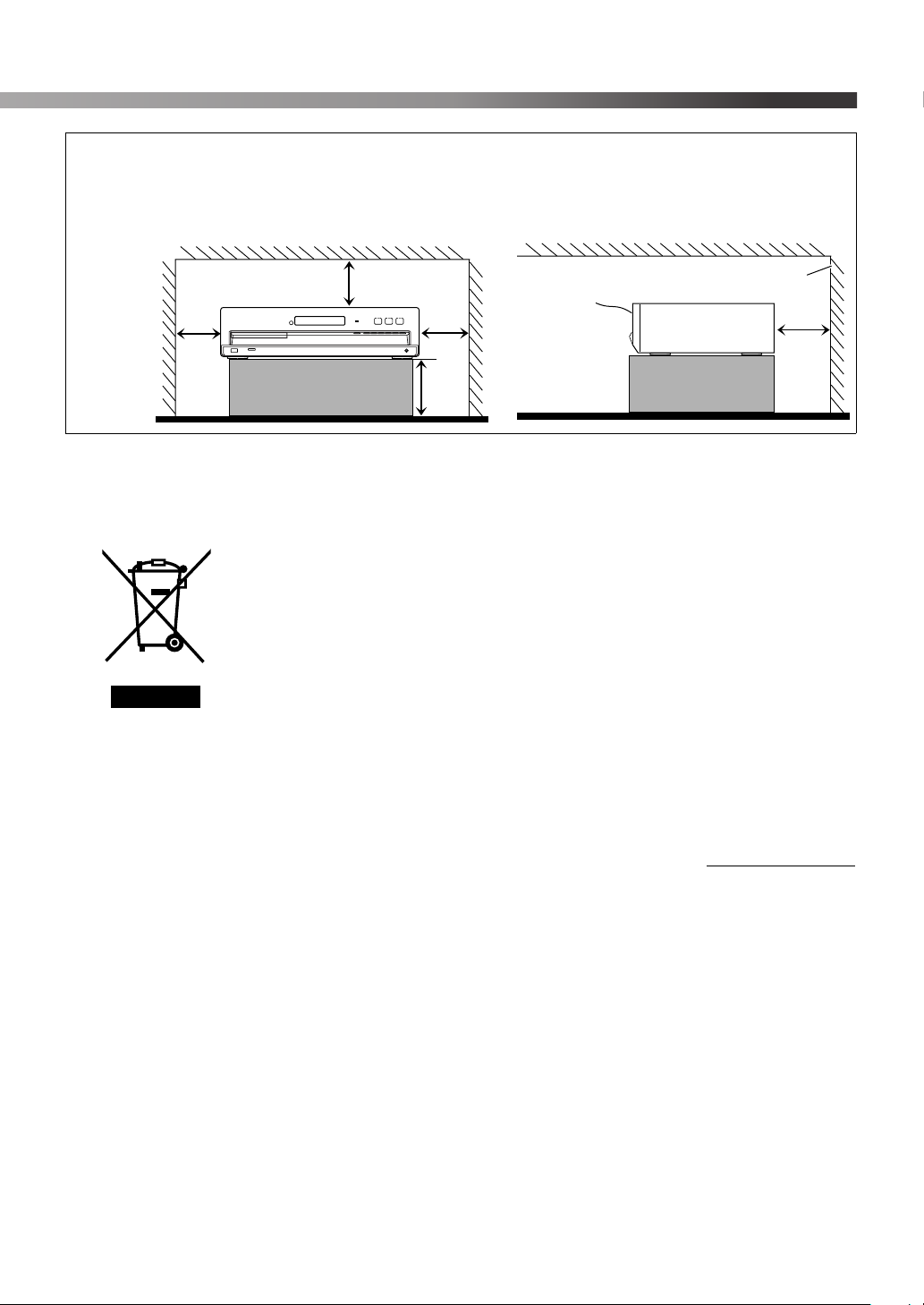
Caution: Proper Ventilation
To avoid risk of electric shock and fire and to protect from damage, place the apparatus on a level surface. The minimal
clearances are shown below:
Front view
Wall or
obstructions
XV-THD51
15 cm
15 cm
15 cm
No obstructions
15 cm
Information for Users on Disposal of Old Equipment
[European Union]
This symbol indicates that the electrical and electronic equipment should not be
disposed as general household waste at its end-of-life. Instead, the product should
be handed over to the applicable collection point for the recycling of electrical and
electronic equipment for proper treatment, recovery and recycling in accordance with
your national legislation.
By disposing of this product correctly, you will help to conserve natural resources
and will help prevent potential negative effects on the environment and human health
which could otherwise be caused by inappropriate waste handling of this product.
For more information about collection point and recycling of this product, please
Attention:
This symbol is only valid
in the European Union.
contact your local municipal office, your household waste disposal service or the
shop where you purchased the product.
Penalties may be applicable for incorrect disposal of this waste, in accordance with
national legislation.
Front
Side view
XV-THD51
Wall or
obstructions
15 cm
(Business users)
If you wish to dispose of this product, please visit our web page www.jvc-europe.com
to obtain information about the take-back of the product.
[Other Countries outside the European Union]
If you wish to dispose of this product, please do so in accordance with applicable
national legislation or other rules in your country for the treatment of old electrical
and electronic equipment.
G-2
Page 4
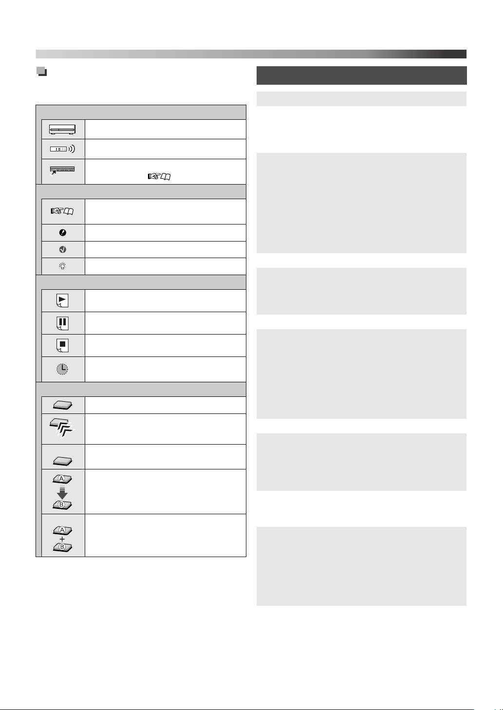
How to read this manual
«
The following icons and illustrations are used to make the
explanations simple and easy-to-understand.
Icons for System operations
Operations from the center unit
Operations from the remote control
The function can be operated from the
on-screen bar ( 21).
Icons for the references and notes
Reference page for the function/
operation
Caution for the function/operation
Note for the function/operation
Tip for the function/operation
Icons for operating information
The function is available while playing.
The function is available while paused.
The function is available while stopped.
There is a time limit on performing the
target operation.
Illustrations for button operations
Press the button briefly.
Press the button repeatedly.
«Hold
Hold
Press and hold the button.
Press button A, then press button B.
Press button B while holding button A.
Table of contents
Before using this System ............................................... 2
Playable discs/devices/files............................................ 3
Playable disc types ...................................................... 3
Playable digital devices............................................... 3
Playable file types ....................................................... 4
Getting started ............................................................... 5
Checking the supplied accessories .............................. 5
Putting batteries into the remote control ..................... 5
Attaching the stands to the front speakers ................... 5
Speaker layout and connection .................................... 5
Connecting the AM (MW) and FM antennas.............. 7
Connecting a TV ......................................................... 7
Connecting external components ................................ 8
Connecting the AC power cord................................... 8
Basic and common operations...................................... 9
Sound and monitor settings........................................ 11
Sound settings and adjustments................................. 11
Monitor settings......................................................... 12
Audio/video settings for external components.......... 13
iPod playback .............................................................. 14
Disc/file playback ........................................................ 15
Basic playback........................................................... 15
Using the disc menu .................................................. 17
Locating a desired scene or song...............................17
Changing the playback mode .................................... 18
Advanced operations ................................................. 19
Special playback for DVD Audio.............................. 20
Operation from the TV screen................................... 21
Personal settings .......................................................... 23
Tuner operations ......................................................... 25
Tuning in to a station................................................. 25
Presetting stations...................................................... 25
Selecting the FM reception mode.............................. 25
Receiving FM stations with Radio Data System....... 26
Operating external components................................. 29
Setting the manufacturer’s code ................................ 29
Operating external components................................. 29
References .................................................................... 30
Manufacturer’s code list ............................................ 30
Messages and icons shown on the TV....................... 31
Available surround modes......................................... 31
Language code list..................................................... 32
Troubleshooting......................................................... 33
Specifications ............................................................ 34
1
Page 5

Before using this System
Precautions
There are no user-serviceable parts inside. If anything
goes wrong, unplug the power cord and consult your
dealer.
Notes on installing the System
• Select a location which is level, dry and neither too hot nor
too cold between 5°C and 35°C.
• Do not install the System in a location subject to
vibrations.
• Do not put heavy objects on the System.
Avoid moisture, water, dust, and high
temperatures
• Do not install the System in moist or dusty locations.
• If water gets inside the System, turn off the power and
remove the plug from the wall outlet, then consult your
dealer. Using the System in this state may cause a fire or
electrical shock.
• Do not expose the System to direct sunlight or place it near
a heating device.
To prevent malfunctions or damage to the System
• Do not insert any metallic objects, such as wires, hairpins,
coins, etc. into the System.
• Do not block the vents.
Notes on the power cord
• When you are away on travel or otherwise for an extended
period of time, remove the plug from the wall outlet. A
small amount of power is always consumed while the
power cord is connected to the wall outlet.
• When unplugging the System from the wall outlet, always
pull the plug, not the power cord.
• Disconnect the power cord before cleaning or moving the
System.
• Do not modify, twist or pull the power cord, or put
anything heavy on it. Doing so may cause fire, electric
shock, or other accidents.
About copyright laws
Observe the copyright laws in your country before recording
from original sources. Recording of copyrighted material
may infringe copyright laws.
About the copyguard system
The discs are protected by the copyguard system. When
connecting the System to a TV via a VCR, or to a TV with a
built-in VCR, the copyguard system activates and distortion
of the picture may occur.
Notes on installing and using the speakers
• Place the speakers and subwoofer on a flat and level
surface.
• The speakers are magnetically shielded to avoid color
distortions on TVs. If the color on a TV is distorted,
perform the following procedure:
– Turn off the TV’s main power switch or unplug it
before installing the speakers. Then wait at least
30 minutes before turning on the TV’s main power
switch again.
Some TVs may still be affected even though you have
followed the above procedure. If this happens, move the
speakers away from the TV.
• The subwoofer is not magnetically shielded. To avoid
color distortion, do not place it near the TV or monitor.
• When moving the speakers and subwoofer, do not pull the
speaker cords. Doing so may cause the speakers and/or
subwoofer to fall over, causing damage or injury.
• When installing the speakers on a wall, be sure to have
them installed by qualified personnel. DO NOT install the
speakers on a wall by yourself.
• Do not lean against the speakers, as they could fall down
or break, possibly causing an injury. Be especially careful
that children do not lean against them.
About the adjustment of volume
Always set the volume to the minimum level before starting
any source. If the volume is set at a high level, the sudden
blast of sound could permanently damage your hearing and/
or blow out the speakers.
To clean the System
• Use a soft cloth. Follow the relevant instructions on the
use of chemically-coated cloths.
• If the System is heavily stained, apply a small amount of
water or neutral detergent to the cloth and wipe clean, then
wipe with a dry cloth.
• Do not use benzene, thinner or other organic solvents and
disinfectants. These may cause deformation or
discoloring.
2
Page 6
Playable discs/devices/files
Some discs/files may require operations that differ
from those explained in this manual.
Some discs/devices/files may not be recognized or
played back correctly due to their characteristics.
Playable disc types
Type of format Types of media
• Discs on the market
DVD Video
DVD Audio
Super Video CD
(SVCD)/Video CD
(VCD)
Audio CD (CD-DA)
DVD VR • DVD-R/-RW
Audio/video files
(4)
It is possible to play back finalized +R/+RW (DVD
Video format only) discs. “DVD” lights on the display
panel when a +R/+RW disc is loaded.
DVD-R/-RW: This System does not support “multiborder” discs.
CD-R/-RW:
– This System supports “multi-session” discs (up to
20 sessions).
– This System cannot play “packet write” discs.
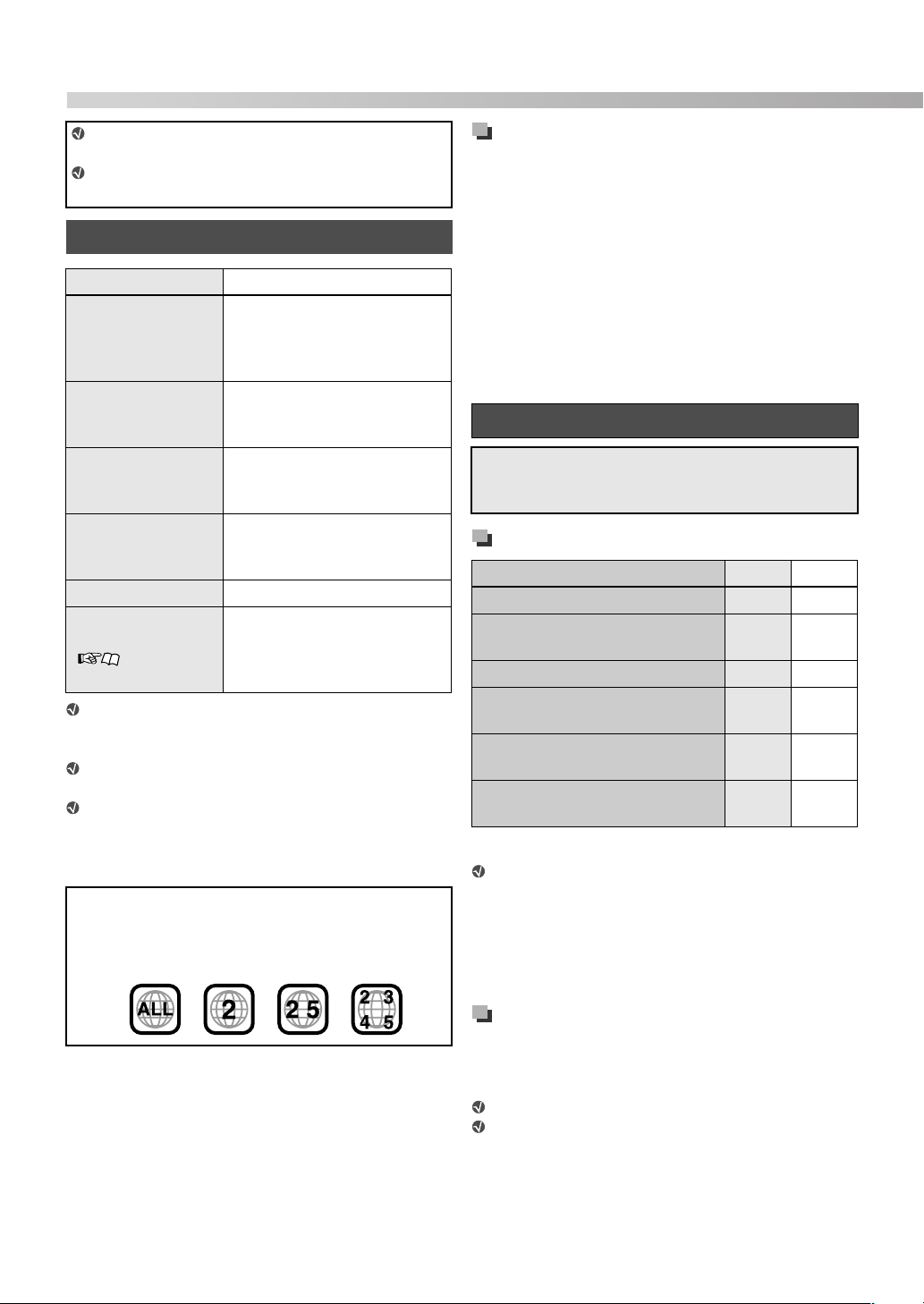
Region code of DVD Video
DVD Video players and DVD Video discs have their own
Region Code numbers. This System can play back DVD
Video discs whose Region Code numbers include “2.”
Ex.:
• DVD-R/-R DL/-RW
• +R/+RW
• DualDisc* (DVD side only)
• Discs on the market
• DVD-R/-R DL/-RW
• +R/+RW
• Discs on the market
• CD-R/-RW
• Discs on the market
• CD Text (Audio part only)
• CD-R/-RW
• DVD-R/-R DL/-RW in UDF
Bridge format
• CD-R/-RW in ISO 9660
format
Unplayable discs—unwarranted
Playing back the following discs generates noise and
damages the speakers.
• DVD-ROM, DVD-RAM, DualDisc* (non-DVD side)
• CD-ROM, CD-I (CD-I Ready), Photo CD, SACD
• Unfinalized discs (except DVD VR)
• Discs with an irregular shape or discs with tape, stickers
or paste on either the label side or playback side
• Warped, dirty, or scratched discs
The Non-DVD side of a “DualDisc” does not comply with
*
the “Compact Disc Digital Audio” standard. Therefore, the
use of Non-DVD side of a DualDisc on this product may
not be recommended.
Playable digital devices
JVC bears no responsibility for any loss of data in an
iPod and USB mass storage class device while using this
System.
iPod
iPod model AUDIO VIDEO
iPod nano 1GB/2GB/4GB √
iPod nano (2nd Generation)
2GB/4GB/8GB
iPod mini 4GB/6GB √
iPod (4th Generation)
20GB/40GB
iPod photo (4th Generation)
20GB/30GB/40GB/60GB
iPod video (5th Generation)
30GB/60GB/80GB
* Only still pictures are available.
If the iPod does not play correctly, update your iPod
software to the latest version. For details about
updating your iPod, check on the Apple web site
<http://www.apple.com>.
iPod is a trademark of Apple Inc., registered in the U.S. and
other countries.
USB mass storage class device
A USB flash memory device, hard disk drive, multimedia
card reader, digital camera, etc. can be used with this System
through USB connection.
This System is compatible with USB 2.0 Full Speed.
This System cannot recognize a USB mass storage
class device whose rating exceeds 5 V/500 mA.
√
√
√√ *
√√
3
Page 7
Playable file types
The following files in a disc or a USB mass storage class
device can be played back.
Type of file Extensions
MP3 <.mp3>
Audio
Picture JPEG <.jpg>, <.jpeg>
Movie
If a file on a USB mass storage class device exceeds
the following conditions, it may not be played back
correctly:
– Maximum data transfer rate: 2 Mbps
– Maximum frame rate: 30 fps for progressive
– Maximum file size: 2 GB
The System recognizes up to 150 tracks (files) per
group, and 99 groups per disc/device. The total
number of tracks (files) that the System can detect is
4 000.
Information about the recording
conditions for the files on a disc/
device
MP3/WMA files
• The System supports MP3/WMA files recorded at a bit
rate of 32 kbps – 320 kbps and a sampling frequency of
16 kHz, 22.05 kHz, 24 kHz*, 32 kHz, 44.1 kHz, or
48 kHz.
• It is recommended to record each file at a sample rate of
44.1 kHz and at a data transfer rate of 128 (96*) kbps.
*
For WMA only
WAV files
• The System supports WAV files recorded at a
quantization rate of 8 bit or 16 bit and a sampling
frequency of 8 kHz, 11.025 kHz, 12 kHz, 16 kHz,
22.05 kHz, 24 kHz, 32 kHz, 44.1 kHz, or 48 kHz.
• It is recommended to record each file at a sample rate of
44.1 kHz and at a quantization rate of 16 bit Linear PCM.
WMA <.wma>
WAV <.wav>
ASF <.asf>
MPEG-1 <.mpg>, <.mpeg>
MPEG-2
DivX (6.x, 5.x,
4.x and 3.11)
<.mpg>, <.mpeg>,
<.mod>
<.divx>, <.div>,
<.avi>
JPEG files
• It is recommended to record a file at 640 x 480 resolution.
(If a file has been recorded at a resolution of more than
640 x 480, it will take a longer time to be displayed.)
• This System can only play baseline JPEG files.
ASF files
• The System supports MPEG-4 files with the following
conditions:
File format: ASF
Visual profile: MPEG-4 SP (Simple Profile)
Audio CODEC: G.726
Max. picture size: 352 x 288 (CIF)
Max. bit rate: 384 kbps
MPEG1/MPEG2 files
• The stream format should conform to the MPEG system/
program stream.
• 720 x 576 pixels (25 fps)/720 x 480 pixels (30 fps) is
recommended for the highest resolution.
• This System also supports resolutions of 352 x 576/
480 x 576/352 x 288 pixels (25 fps) and 352 x 480/
480 x 480/352 x 240 pixels (30 fps).
• The file format should be MP@ML (Main Profile at Main
Level)/SP@ML (Simple Profile at Main Level)/MP@LL
(Main Profile at Low Level).
• Audio streams should conform to MPEG1 Audio Layer-2
or MPEG2 Audio Layer-2.
DivX files
• The System supports DivX files whose resolution is
720 x 480 pixels or less (30 fps), and 720 x 576 pixels or
less (25 fps).
• Audio stream should conform to Dolby Digital (including
multi-channel) or MPEG1 Audio Layer-3 (MP3).
• The System does not support GMC (Global Motion
Compression).
• Files encoded in the interlaced scanning mode may not be
played back correctly.
4
Page 8
Getting started
Checking the supplied accessories
If anything is missing, contact your dealer immediately.
• Remote control (x 1)
• Batteries (x 2)
• FM antenna (x 1)
• AM (MW) loop antenna (x 1)
• Docking station for iPod (x 1)
• Feet (x 8) (For front speakers)
• Stands (x 2) (For front speakers)
• Screws: M5 x 12 mm (x 4) (For front speakers)
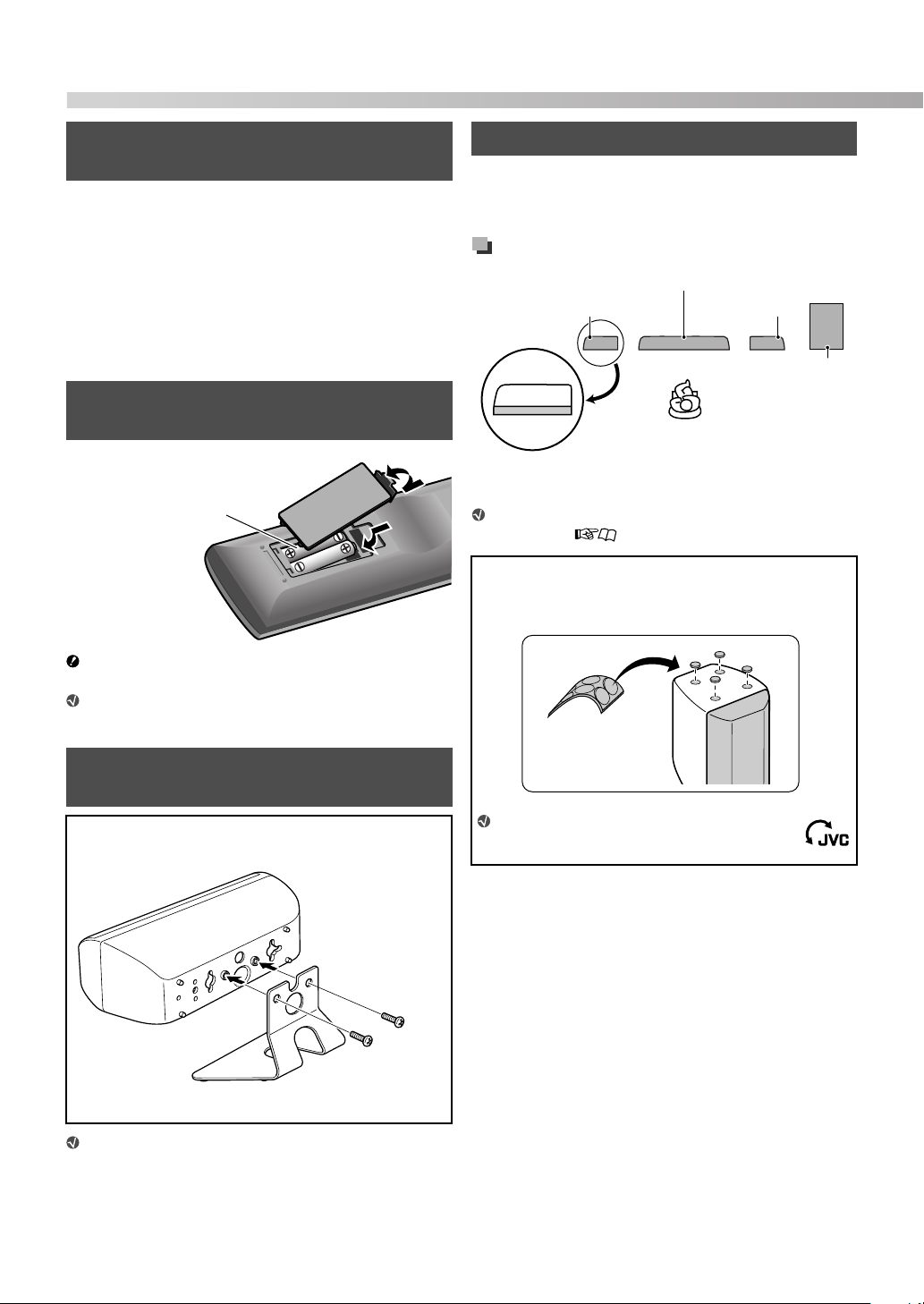
Putting batteries into the remote control
R03 (UM-4)/AAA (24F) type
dry-cell batteries (supplied)
Battery shall not be exposed to excessive heat such
as sunshine, fire or the like.
If the range or effectiveness of the remote control
decreases, replace both batteries.
Speaker layout and connection
You can enjoy the sound of the center channel, surround
right channel, and surround left channel with the center
surround speaker.
Speaker layout
Center surround (CS)
Front left (L) Front right (R)
Subwoofer (SW)
*
* Place each front speaker with the curved-side facing
outward.
Select “S.SPK F” as the speaker position mode for
this layout. ( 11)
Attaching the feet
When placing the front speakers vertically, attach the feet
as illustrated.
Peel off.
Feet (supplied)
Attaching the stands to the front speakers
To place the front speakers horizontally, attach a stand to
each one.
Screws
Stand (supplied)
You can install the front and center surround
speakers on the wall. When installing the front
speakers on the wall, do not attach the stands.
5
M5 x 12 mm
(supplied)
You can turn the JVC logos to make
them legible.
Page 9
Do not connect the power cord
until all other connections have
been made.
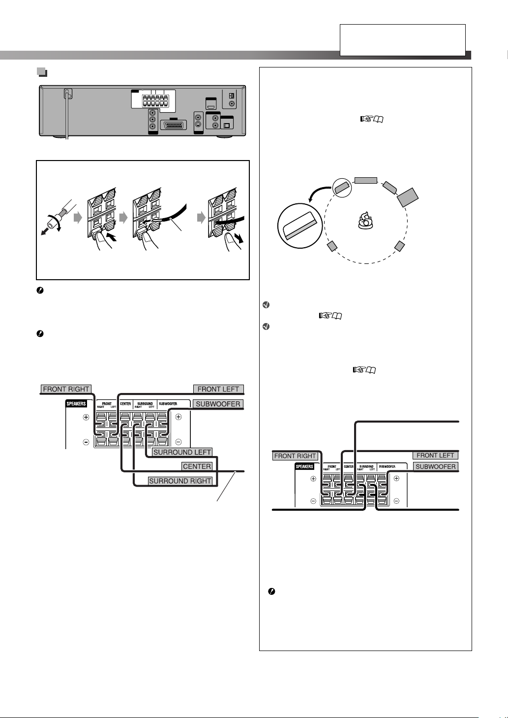
Speaker connection
Center unit
Connecting the speaker cords
Connect the speaker cords to the center unit.
Speaker cord
• Connect the black cords to the r terminals.
• Connect the gray cords to the q terminals.
If you connect the speakers other than those
supplied for the System, use speakers of the same
speaker impedance (SPEAKER IMPEDANCE)
indicated on the rear of the center unit.
DO NOT connect more than one speaker cord to one
speaker terminal.
From front right speaker
(SP-THD51F)
From front left speaker
(SP-THD51F)
From
subwoofer
(SP-THD51W)
Optional speaker layout and connection
You can connect separately purchased speakers to the
System as the center, surround right, and surround left
speakers.
• See “Attaching the feet” ( 5) and “Connecting the
speaker cords” on the left column before connecting.
Speaker layout
Front left (L)
Center (C)
Front right (R)
Subwoofer
(SW)
*
Surround left
(LS)
* Place each front speaker with the curved-side facing
outward.
Surround right
(RS)
Select “S.SPK R” as the speaker position mode for
this layout. ( 11)
To obtain the best possible surround sound from
this System, place all the speakers except the
subwoofer at the same distance from the listening
position. If it is impossible, adjust the delay time
from DELAY menu. ( 24)
Speaker connection
From center speaker
(separately purchased)
From front right speaker
(SP-THD51F)
From front left speaker
(SP-THD51F)
*
From center surround speaker
(SP-THD51C)
From subwoofer
(SP-THD51W)
From surround right speaker
(separately purchased)
* You can use the supplied center surround speaker as the
center speaker.
When you connect the center surround speaker, connect
only the CENTER speaker cord to the CENTER speaker
terminal of the center unit.
When you connect the supplied center surround speaker
as the center speaker, be sure to keep the followings for
the unused cords and handle them with care.
– Do insulate the SURROUND RIGHT and SURROUND
LEFT speaker cords with insulating tape.
– Do not let the unused cords touch any materials.
From surround left speaker
(separately purchased)
6
Page 10
Getting started
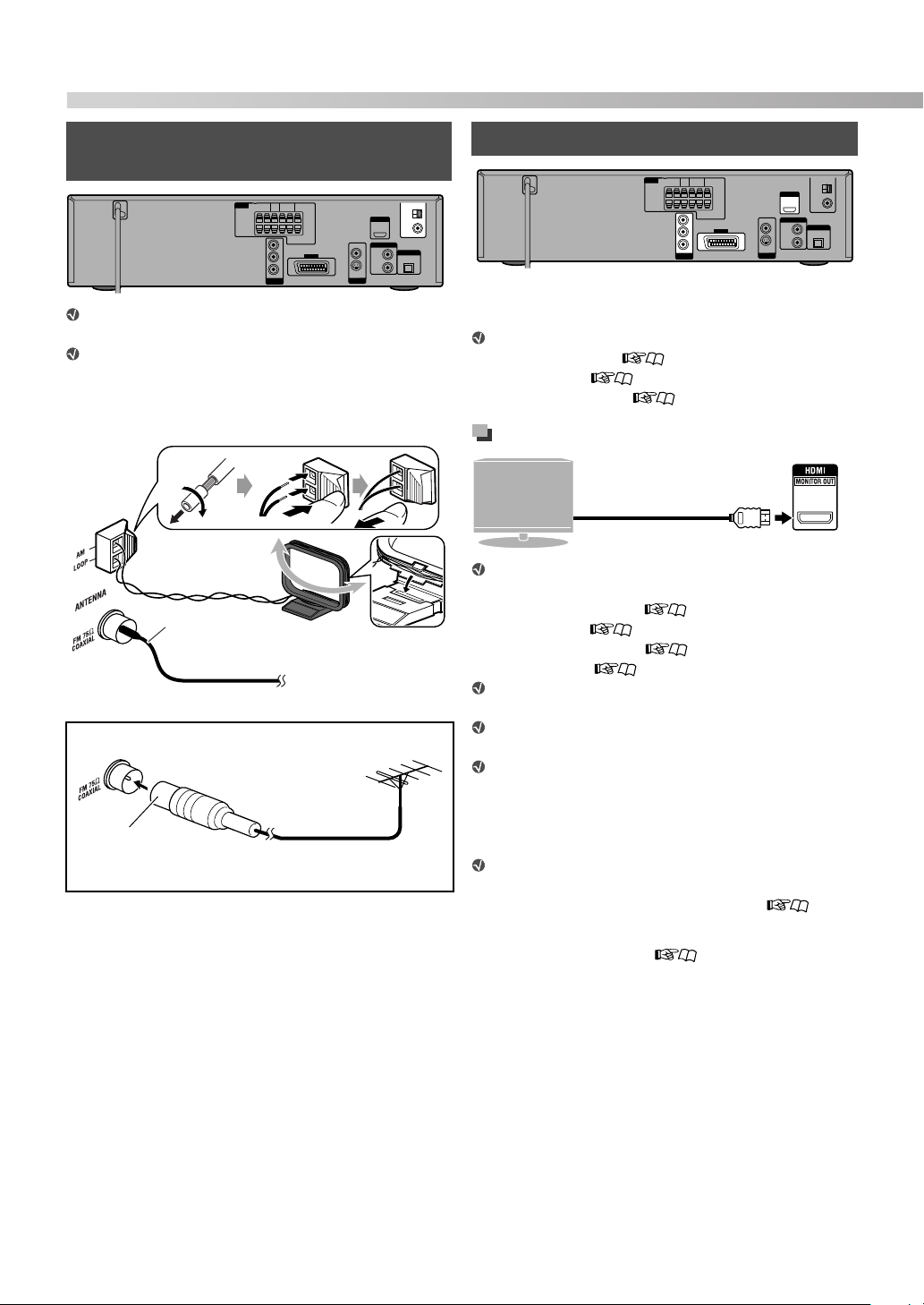
Connecting the AM (MW) and FM antennas
Make sure the antenna conductors do not touch any
other terminals, connecting cords or power cords.
Keep the AM loop antenna cable wrapped around
the AM loop antenna frame, otherwise the
effectiveness and sensitivity of the AM loop antenna
may be reduced.
AM (MW) loop
antenna (supplied)
FM antenna
(supplied)
Extend it horizontally.
For better FM reception
Standard type (75 Ω
coaxial) connector (IEC
or DIN 45325)
Turn it until the best
reception is obtained.
FM outdoor antenna
(not supplied)
FM outdoor antenna cord
(not supplied)
Connecting a TV
Connect the TV to the appropriate video out jacks to view
the playback picture.
Make the following settings after connecting the TV:
– Scanning mode ( 12)
– Monitor out ( 13)
– MONITOR TYPE ( 23)
Connection using the HDMI terminal
From HDMI input
TV
You can make the following settings for the TV when
the HDMI connection is used:
– HDMI DVI COLOR ( 23)
– HDMI OUT ( 23)
– HDMI AUDIO OUT ( 24)
– DOWN MIX ( 24)*
Use a certified HDMI cable, which has the HDMI
logo.
You can use a monitor with a DVI terminal by
connecting with a DVI-HDMI conversion cable.
When you play HDCP (High-Bandwidth Digital
Content Protection) source, allow a few seconds for
the sound and picture to be transmitted to the
speakers and TV while the confirmation process is
completed.
On some TVs, no sound may come out during
playback of sources such as DVD Audio even when
the HDMI AUDIO OUT setting is “ON” ( 24).
This setting is available only when the speaker position
*
mode is set to “S.SPK F” ( 11).
terminal
HDMI cable (not supplied)
7
Page 11
Do not connect the power cord
until all other connections have
been made.
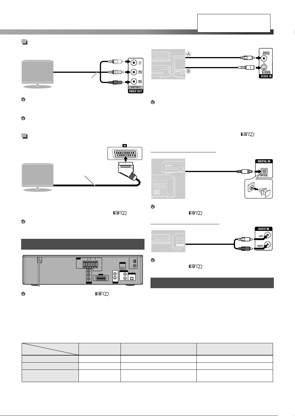
Connection using the component
video jacks
From component
TV
video input
Component video
cord (not supplied)
If your TV does not support progressive video input,
connect a TV via the AV (scart) connector (see
below).
For the BNC connection, use a plug adapter (not
supplied).
Green
Blue
Red
Connection using the scart connector
Scart cable
TV
(not supplied)
To scart connector
*
* Some TVs’ scart connectors emit audio signals. In such a
case, you can enjoy the TV sound through this System by
selecting TV SOUND as the source to play. ( 10)
No sound signal comes out from the AV (scart)
connector.
Connecting external components
,
Video connection
Composite video cord
(not supplied)
VCR, etc.
A From composite video output
B From S-video output
or
S-video cord
(not supplied)
Align the
5 marks.
To view a video from the external component
connected as above:
– Connect a TV via the AV (scart) connector (see
the left column).
– Select an appropriate video input setting
according to the video connection. ( 13)
Audio connection
Connecting a digital component
Digital optical cable
(not supplied)
STB (Set Top
Box), etc.
From digital optical output
Select “OPT” as the audio input setting before
playing back. ( 13)
Connecting an analog component
RCA pin plug cord
VCR, etc.
(not supplied)
From audio output
Select “2CH” as the audio input setting before
playing back. ( 13)
Connecting the AC power cord
Select “VIDEO” as the source ( 10) for playing
a component connected as follows.
Available video output terminals for each source
Terminal
Source
HDMI √ ——
COMPONENT √ ——
AV (scart) √
DVD
USB
Plug in the System only after all other connections have
been completed.
√: Available —: Not available
IPod VIDEO
(Composite signal only)
√
(Composite signal only)
√
8
Page 12
Basic and common operations
How to use the number buttons
To select 3: Press 3.
To select 10: Press 10.
To select 14: Press h 10, 1, then 4.
To select 24: Press h 10, 2, then 4.
To select 40: Press h 10, 4, then 0.
To select 114: Press h 10, h 10, 1, 1, then 4.
Set the remote control
mode before
operation.
Point at the remote sensor
directly.
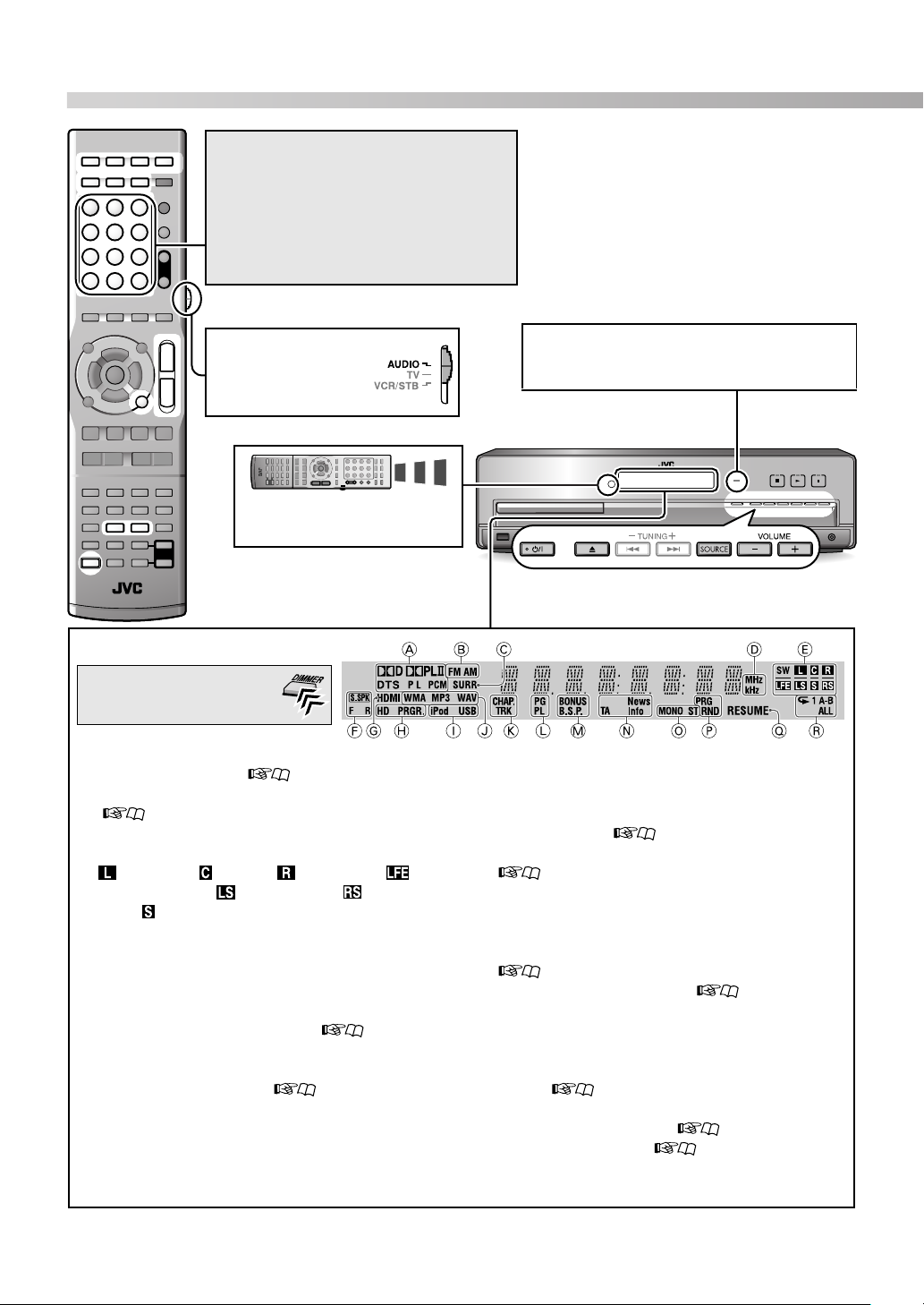
Display
To change the display
brightness
A Digital audio signal format indicators
B Tuner band indicators ( 25)
C Lights when one of the surround modes is activated.
( 12)
D Frequency unit indicators for FM/AM
E Signal and speaker indicators
(front left), (center), (front right), (low
frequency effect), (surround left), (surround
right), (monaural surround): Lights when the signal
comes in for the digital input or when the System is
ready to receive the signal for the analog input.
SW (subwoofer): Always lights.
_: Lights while reproducing the channel’s sound
through the speaker.
F Speaker position mode indicators ( 11)
G Lights when both the System and the TV (with HDMI
connection) are ready to communicate each other.
H Scanning mode indicators ( 12)
HD: Lights when “720P” or “1080I” is selected.
PRGR.: Lights when the progressive scanning mode is
activated.
I Digital device indicators
J File type indicators
STANDBY lamp:
• Goes off when the System is turned on.
• Lights when the System is turned off.
K Lights when the chapter (CHAP.) or track (TRK)
number is displayed.
L Lights when selecting a program number (PG) or
playlist number (PL) of a DVD VR disc by using
TITLE/GROUP. ( 17)
M Special playback indicators for DVD Audio
( 20)
BONUS: Lights when a bonus group is detected.
B.S.P: Lights when browsable still pictures are
detected.
N Program type (for Radio Data System) indicators
( 26)
O FM reception mode indicators ( 25)
MONO: Lights when receiving an FM stereo station in
monaural.
ST: Lights when receiving an FM stereo station.
P Lights during program play (PRG) or random play
(RND). ( 18)
Q Lights when the System memorizes the position where
the playback is interrupted. ( 16)
R Repeat mode indicators ( 18, 21)
9
Page 13

Turning the power on or off
To turn off the System by using the sleep timer
– – (off) = 10 = 20 = 30 = 60 = 90 = 120
= 150 = 180 = (back to the beginning)
(unit: minutes)
To check the remaining time, press the button once.
Selecting the source
Adjusting the volume
To turn off the sound instantly
“MUTING” is shown on the display.
To restore the sound, press the button again, or adjust the
volume level.
To do Indication
Play back a disc DVD 15
Play back a file on a
USB mass storage
class device
Play back an iPod IPod 14
Listen to an FM or
AM (MW) station
Play back an
external component
Listen to the sound
from the TV
connected via the
AV (scart)
connector.
To select the source from the center unit
*
Make sure that the appropriate audio and video input
settings have been made for the source. For details about the
settings, see “Setting the audio input” and “Setting the video
input”( 13).
«Hold
USB 15
FM or AM 25
VIDEO* 29
TV SOUND 8
Prohibiting disc ejection
1 Turn off the System.
2 Lock the disc tray.
«Hold
(On the center unit)
To unlock the disc tray, perform the above procedure
again. “UNLOCKED” appears on the display.
Listening with headphones
Be sure to turn down the volume before connecting
or putting on the headphones.
When headphones are connected, the System automatically
deactivates the speakers and cancels the surround mode
( 12) temporarily.
• “H.PHONE” appears on the display.
While a multi-channel source is played back, the
channel signals are down-mixed.
“LOCKED” appears on the
display.
10
Page 14

Sound and monitor settings
Adjusting the output level of the
Set the remote
control mode
before operation.
speakers and subwoofer
1
• When the speaker position mode is “S.SPK F”:
• When the speaker position mode is “S.SPK R”:
The items you can adjust differ depending on
the selected speaker position mode (see the
left column).
CENTER = SURR = SUBWFR = (back to
the beginning)
FRNT L = FRNT R = CENTER = SURR L
= SURR R = SUBWFR = (back to the
beginning)
2 Adjust the output level.
Sound settings and adjustments
Selecting the speaker position
mode
For optional speaker layout ( 6), change the speaker
position mode.
1 Turn off the System. ( 10)
«Hold
2
3 Select “S.SPK R.”
S.SPK F
(Surround
speaker: Front)
S.SPK R
(Surround
speaker: Rear)
As the speaker position mode is changed, the
following settings are also changed automatically:
– The output level settings of the speakers and of
subwoofer (see the right column) are initialized.
– The surround mode ( 12) is set to “AUTO
SUR.”
Initial setting
• The F indicator
lights on the display.
For optional speaker
layout
• The R indicator
lights on the display.
Different output level settings can be stored for the
two groups of sources—FM/AM and the others.
You can also make adjustments from the LEVEL
menu ( 24) when the speaker position mode is
“S.SPK R.”
Adjusting the bass and treble
sounds
1
TRE Adjusts the treble sound
BASS Adjusts the bass sound
2 Adjust the level.
11
Page 15

Using the surround mode
Select one of the available surround
modes.
The surround modes you can select depend on the
playback source and the selected speaker position
mode ( 11). For details on each surround
mode, see “Available surround modes”
(31).
• During playback with “S.SPK F” speaker position
mode:
AUTO SUR = MOVIE = WIDE/2CH =
SUPER W = OFF = (back to the beginning)
When the source is “FM” or “AM,” the surround
mode cannot be activated.
Monitor settings
Setting the scanning mode
Select the scanning mode for the sources “DVD”
and “USB” according to the type of TV and to connection
method.
1 Select “DVD” or “USB” as the source.
(10)
«Hold
2
3 Select an appropriate scanning mode, then
confirm the selection.
• When the speaker position mode is “S.SPK R”:
During 2-channel playback:
AUTO SUR = MOVIE = MUSIC = STADIUM
= ALL ST = OFF = (back to the beginning)
When the source is “FM” or “AM,” you can only
select “ALL ST.”
During multi-channel playback:
AUTO SUR = currently selected mode* = OFF
= (back to the beginning)
When “AUTO SUR” is selected, the System
*
automatically selects a proper multi-channel
surround mode, such as “DOLBY D (Dolby Digital)”
or “DTS (DTS Digital Surround).”
To check the surround mode currently selected, press
SURROUND once.
During playback of ASF, MPEG-2, or MPEG-1 files,
the surround mode setting is ineffective.
During playback of DivX, the surround mode setting
is effective only for multi-channel files with “S.SPK R”
selected as the speaker position mode.
For DVD Audio, when “LR ONLY” appears on the
display, activate the surround mode for the multichannel reproduction.
Select Confirm
• When connecting the TV via the HDMI
MONITOR OUT terminal ( 7), select
“AUTO,” “1080I,” “720P,” or “576P.”
• When connecting the TV via the COMPONENT
jacks ( 8), select “576P.”
• When connecting the TV via the AV (scart)
connector ( 8), select “RGB” or “Y/C.”
Select for the TV accommodating the
RGB
Y/C
1080I
576P
720P
AUTO
You can get better picture quality in the following
orders:
– 1080I > 720P > 576P
– RGB >Y/C
If the HDMI MONITOR OUT terminal and the AV
(scart) connector are both connected to a TV or TVs,
you cannot change the scanning mode for the AV
(scart) connector.
When the scanning mode does not correspond to
that of the TV, the picture is not displayed normally.
interlaced RGB/composite video
signal.
Select for the TV accommodating the
interlaced S-video signal.
To watch the picture in interlaced
scanning mode.
To watch the picture in progressive
scanning mode.
The System automatically emits the
video signal to give you the best
picture quality on your TV.
12
Page 16

Sound and monitor settings
See page 11 for button
locations.
Setting the monitor out
parameter
Select the video output jack type of the TV you will use to
watch the playback. ( 7)
1
2 Select “MON. (monitor).”
Item Current setting
3 Select an appropriate video output according to
the TV connection.
SCART
HDMI
COMP
For connection via the AV
(scart) connector
For connection via the
HDMI MONITOR OUT
terminal
For connection via the
COMPONENT jacks
Audio/video settings for external components
Setting the video input
Set the video input of the external component for
“VIDEO.”
1
2 Select “VIN. (video input).”
Item
Current setting
3 Select an appropriate video input according to
the video connection. ( 8)
For connection via the S-
S
VIDEO jack
For connection via the
CV
VIDEO (composite) jack
Setting the audio input
Set the audio input of the external component for
“VIDEO.”
1
Select “AIN. (audio input).”
2
Item
Current setting
3 Select an appropriate audio input according to
the audio connection. ( 8)
2CH
OPT
For connection via the
AUDIO IN jacks
For connection via the
DIGITAL IN terminal
13
Page 17

iPod playback
Set the remote control mode before
operation.
Before selecting the video
source to play
Make the appropriate setting for
video output on the iPod.
Starting playback
DO NOT connect or disconnect the iPod when the
System is turned on.
Be sure to reduce the volume on the System to the
minimum level before connecting an iPod. Adjust the
volume after playback has started.
1 Connect an iPod while the System is turned off.
Play/pause/search/skip
To do
Start playback
Pause
Fast-forward/fast-reverse
search within the current
track
Skip to the next/previous
item*
* While playing back a video
• The iPod enters sleep mode when you turn off the System
or select another source.
• To show the still pictures in the iPod, play them back in
slide-show mode on the iPod.
DO NOT touch the iPod terminal pins or the
connector pins.
When the iPod is not charged through the System,
the iPod may not be turned on from the System.
If the sound is distorted when audio sources with
high recording levels are played, you are
recommended to deactivate the equalizer on your
iPod.
To view a video/picture from the iPod on the TV,
connect the System to the TV via the AV (scart)
connector. ( 8)
You cannot send any data to your iPod from the
System.
The iPod battery is charged only when “IPod” is
selected as the source.
«Hold
«Hold
Docking station for
iPod (supplied)
* Attach the dock adapter (supplied for the iPod or
separately purchased) before placing the iPod.
(33)
• Connect the plug with the arrow-mark side facing up.
2 Turn on the System, then select “IPod” as the
source. ( 10)
“CONNECT” appears on the display. If the iPod is not
connected firmly, “NO CONNE” appears.
3 Start playing the iPod.
• Press 3 (play button) again if the iPod does not start
playback.
If the iPod which is not listed in “Playable digital devices”
( 3) is connected, the iPod may not be operated from
the System. In this case, deactivate the iPod battery charge
function so that the iPod may be operated, but the iPod
cannot be charged through the System.
To deactivate the battery charge function
*
«Hold
To use the battery charge function, perform the above
procedure again. “P.ON” appears on the display.
“P.OFF” appears on the display.
14
Page 18

Disc/file playback
The following icons show the available disc/file types for
the target function:
Initial settings
Make the following settings before playing back discs/
files.
• Scanning mode ( 12)
• Monitor out ( 13)
• MONITOR TYPE ( 23)
• ON SCREEN LANGUAGE ( 23)
Set the remote control mode
before operation.
For disc playback
For playback of a file on a USB
mass storage class device
Basic playback
Playing back a disc
1 Select “DVD” as the source. ( 10)
2
3 Place a disc on the tray.
Label side up
4 Start playback.
• JPEG: Slide-show playback starts.
• MP3/WMA/WAV: The file control display appears
Playing back a file on a USB mass
storage class device
1 Connect a USB mass storage class device while
the System is turned off.
(On the center unit)
When placing an 8 cm
disc
on the TV. ( 22)
Operating the touch sensor
panel
You can operate the playback control
buttons on the center unit simply by
touching them.
When you touch any one of these
buttons, it lights briefly in blue.
If a still picture is displayed for about 5 minutes, the
System automatically dims the screen (screen
saver function). You can deactivate the screen
saver function. ( 23)
When several types of files (music, picture or
movie) are recorded on a disc or device, select
the file type you want to play. (23)
For messages and icons shown on the display, see
“Messages and icons shown on the TV”
(31).
AUX
or
Digital Audio Player
2 Turn on the System, then select “USB” as the
source. ( 10)
Playback starts automatically.
Press 3 (play button) to start playback if the file is not
played back automatically.
• JPEG: Slide-show playback starts.
• MP3/WMA/WAV: The file control display appears
on the TV. ( 22)
15
Page 19

DO NOT connect or disconnect the device when the
System is turned on.
You cannot connect a computer to the USB
MEMORY terminal of the System.
DO NOT connect the device through a USB hub.
iPod does not play through the USB MEMORY
terminal. When iPod is connected to the USB
MEMORY terminal, “RESTRICT” appears on the
display.
This System may not play back some USB mass
storage class devices and does not support DRM
(Digital Rights Management).
When connecting with a USB cable, use the USB 2.0
cable whose length is less than 1 m.
Changing the playback
information
Each time you press the button, the playback
information alternates between “type A” and “type
B” on the display as follows:
Ex.: When a DVD Video disc is played back
Information
type A
Chapter number
Information
type B
Time information
1
*
Play/stop/pause/search
To do
Start playback
Stop playback
Pause
Fast-forward/fast-
reverse search*
1
*
To return to normal playback, press 3 (play button).
2
*
Pressing and holding 4/x also fast-forwards/fastreverses tracks or files.
1
*2
Resume function
The System memorizes the position where
the playback has been interrupted by one of
the following operations:
•Pressing 7 once
• Turning off the power ( 10)
• Changing the source ( 10)
To resume playback, press 3 (play button) or the
corresponding source button.
To clear the memorized position, press 7 twice.
• Opening the disc tray or disconnecting the USB mass
storage class device also clears the memorized position.
«Hold
Title number Chapter number
Disc/
file type
Information type A Information type B
Title (T) number and
chapter (C) number
Chapter number with
time information*
Program (PG)
1
number/Playlist (PL)
number and chapter
(C) number
Track number with
1*2
time information*
Group (G) number
and track (T)
number
File number
1
*
For DVD Video, DVD Audio, DVD VR, VCD, SVCD, or CD,
you can change the time information mode ( 21).
For MP3, WMA, WAV, ASF, MPEG1, MPEG2, or DivX,
elapsed playing time is shown.
2
*
While playing a VCD or SVCD with PBC ( 17), only
track number is displayed.
Group (G) number
and file (F) number
This function does not work in program play and
random play. ( 18)
You can deactivate the resume function.
(24)
16
Page 20

Disc/file playback
Using the disc menu
For DVD Video/DVD Audio
1
For a DVD Video disc For a DVD Audio disc
or
2 Select the desired item, then confirm the
selection.
Select Confirm
For some discs, you can also select items by using
the number buttons.
For VCD/SVCD with PBC
The Play Back Control function (PBC) allows you
to operate the VCD/SVCD using menus.
Select the number of the desired
item while the menu is displayed on
the TV.
• To move to the next or previous page
• To return to the previous menu
To perform playback without PBC
• While playback is stopped, select the desired track by
• While playback is stopped, select the desired track by
To activate the PBC function, press TOP MENU(/PG) or
MENU(/PL).
*
*
of the current menu
using the number buttons.*
pressing x repeatedly, then press 3 (play button).
While playing back a VCD or SVCD with PBC
(“PBC” is shown on the display), some functions
such as time search do not work.
For details on using the number buttons, see “How to use the
number buttons” ( 9).
Locating a desired scene or song
Selecting the beginning of a desired
scene or song
To do Disc/file
1
*
Skip chapter/track/file
2
*
Select the chapter/
track/file number*
Select the title/
program or playlist/
group number*
• Enter the number
while “– –” is flashing
on the display
The features above may not work for some discs/
files.
1
For DVD Video, DVD VR, VCD, and SVCD discs, this
*
function is not available while playback is stopped.
2
*
For DVD Video and DVD VR discs, you can select a title/
program while playback is stopped.
3
*
For details on using the number buttons, see “How to use the
number buttons” ( 9).
4
*
When selecting the chapter/track/file number from the onscreen bar, see “Using the on-screen bar” ( 21).
Selecting the desired position of a
scene or song
To do Disc/file
Move the playback
position back by
10 seconds (one-touch
replay)*
1 *2
3 *4
3
17
Skip in approximately
5-minute intervals*
1
*
This function works only within the same title/program/file.
2
*
This function is not available during repeat play.
1
Page 21

See page 15 for button
locations.
Changing the playback mode
Program play and random play cannot be used for a USB
mass storage class device.
Programing the playing
order—program play
1
Program window
2 Select the desired chapters/
tracks.
• For DVD Video, DVD Audio,
MP3 and WMA: Enter a title/group
number, then a chapter/track
number.*
• For VCD, SVCD and CD: Enter a track number.*
To clear the programs
One by one All programs at once
«Hold
3
To check the program contents
To return to normal playback
Press the button repeatedly until both the
program window and
disappear from the TV.
To program the tracks in the bonus group on a DVD
Audio disc, perform the “Playing back a bonus group”
procedure ( 20) before operation.
You can program up to 99 steps.
For details on using the number buttons, see “How to use the
*
number buttons” ( 9).
Playing at random—random
play
1
2
To return to normal playback
Press the button repeatedly until both the
program window and
disappear from the TV.
To play the tracks in the bonus group on a DVD
Audio disc during random play, perform the “Playing
back a bonus group” procedure ( 20) before
operation.
Playing repeatedly—
repeat play
The repeat modes you can
select depend on the
playback discs/files.
On the
display
ALL
1
No
indication
You can repeat the desired part from the on-screen
bar (A-B repeat). ( 21)
For VCD and SVCD discs, this function is available
only when PBC ( 17) is deactivated.
For DVD Video and DVD VR discs, this function is not
*
available while playback is stopped.
On the TV Meaning
REPEAT GROUP
REPEAT ALL
,
REPEAT TRACK,
REPEAT STEP
,
Repeat current group
Repeat current title
Repeat current
program
Repeat current
playlist
Repeat all titles/
programs/tracks/files
Repeat current track
Repeat current
chapter
Repeat mode is
deactivated
*
18
Page 22

«
Disc/file playback
Advanced operations
Changing the language/sound/scene
angle
To do Disc/file
Select the subtitle
2
1 *2
«Hold
language*
• To show/hide the
subtitle, press
SUBTITLE.
Select the audio
language/audio
channel*
Select the view angle
For DVD Audio, the functions take effect for the
moving picture part only.
1
For DVD VR and SVCD discs, the subtitle indication
*
appears and can be changed by performing the above
procedure even if no subtitles are recorded.
2
*
Some subtitle or audio languages are abbreviated in the
pop-up window. See “Language code list” ( 32).
Special picture playback
To do
Play back
frame-by-frame
Play back in
slow-motion*
Enlarge the picture*2 *
1
Hold
3
• Change the scene
magnification, then
move the zoomed-in
area.
To return to normal playback
• While playing back frame-by-frame or in slow-motion,
press 3 (play button).
• While zooming in on the picture, select “OFF” by pressing
ZOOM repeatedly while holding SHIFT.
For DVD Audio, the functions take effect for the
moving picture part only.
1
For DVD Video and DVD Audio, reverse slow-motion is also
*
available by pressing
2
*
For JPEG files, you can zoom in only during pause.
3
*
On some files, using cursor (3/2/K/5) cannot move the
zoomed-in area during playback.
( SLOW repeatedly.
Disc/file
19
Page 23

See page 15 for button
locations.
Adjusting the picture
quality (VFP)
You can adjust the picture quality.
1
2 Select the desired preset, then finish the setting.
Select
NORMAL Normally select this.
CINEMA Suitable for movies
USER1/
USER2
To adjust the picture tone
You can adjust parameters that affect
picture appearance. (See below.)
Finish
1 Select “USER1” or “USER2” (see above).
2 Select a parameter, then confirm the selection.
Select
GAMMA
BRIGHTNESS
CONTRAST Controls the contrast
SATURATION Controls the color depth
TINT Controls the tint
SHARPNESS Controls the sharpness
Controls the brightness of the
neutral color
Controls the brightness of the
entire picture
Confirm
3 Adjust the parameter, then confirm the
selection.
Special playback for DVD Audio
Playing back a bonus group
Some DVD Audio discs have a “bonus group.”
To play back a bonus group, you have to enter the specific
“key number” (a password).
The way of getting the key number depends on the
disc.
1 Select a bonus group.
The key number entry screen appears.
On the TV On the display
2 Enter the key number, then confirm the entry.
Confirm
Enter the number
When the key number is accepted, playback starts and
the BONUS indicator goes off.
• If playback does not start, enter correct key number
again.
To clear the key number entry
Selecting browsable still
pictures
While playing back a track linked to browsable still pictures
(B.S.P), you can select the still pictures (turn the page).
• If a track is linked to browsable still pictures, they are
usually shown automatically during playback.
Select the desired still picture.
Select
Confirm
4 Repeat steps 2 and 3 to adjust others.
5
When connecting the TV to the HDMI MONITOR
OUT terminal ( 7), the VFP setting has no
effect.
20
Page 24

Disc/file playback
Operation from the TV screen
Using the on-screen bar
You can use various functions from the onscreen bar.
Basic operation procedure
1
2 Select the desired item (see the right column),
then confirm the selection.
Select Confirm
After confirming the selection...
• When the pull-down menu appears, select the desired
item by pressing cursor 5/Y repeatedly, then confirm the
selection by pressing ENTER.
Ex.:
• When a number-entry box appears, enter the number
by using the number buttons (0-9), then confirm the entry
by pressing ENTER.
Ex.:
To correct a misentry:
– setting: press cursor 2 repeatedly to clear the
misentry, then re-enter the number.
– setting: re-enter the number.
• When changing the time information mode ( ),
select the desired item by pressing ENTER repeatedly.
To clear the on-screen bar
Ex.:
Status bar
Function bar
*
On-screen bar functions
Selects the time information mode shown
on the display and the status bar.
1
TIME*
: Elapsed time of chapter/track
1
: Remaining time of chapter/track
REM*
TOTAL: Elapsed time of title (DVD Video)/
group (DVD Audio)/program (DVD
VR)/disc (VCD/CD/SVCD)
T.REM: Remaining time of title (DVD
Video)/group (DVD Audio)/
program (DVD VR)/disc (VCD/
CD/SVCD)
Selects repeat mode.
/////
///:
See also “Playing repeatedly—repeat
play” ( 18).
: Repeats the desired part
2 *3 *4
(A-B repeat).*
After selecting this, select the
beginning point (A) by pressing
ENTER, then the end point (B) by
pressing ENTER again.
Specifies the playback point by the time.
Specifies a chapter to play back from.
Specifies a track to play back from.
Selects the audio language or audio
channel during playback.
Selects the subtitle language during
playback.
Selects the desired scene angle in a multiangle part during playback.
Selects the desired browsable still picture.
1
*
Not available for DVD VR discs
2
*
During playback of DVD Video or DVD VR discs, A-B
repeat play is available only within the same title/program.
3
*
A-B repeat play is not available during program and random
playback.
4
*
During playback of VCD and SVCD discs, A-B repeat play is
available only when PBC ( 17) is deactivated.
The contents of the on-screen bar differ according to
the type of discs/files.
During playback of ASF, MPEG-1, MPEG-2, or DivX files,
*
the function bar does not appear.
21
Page 25

r
See page 15 for button
locations.
Using the file control
display
The file control display appears in the
following cases.
– Audio files: Always appears.
– Movie and picture files: When TOP
MENU(/PG) or MENU(/PL) is pressed or playback
is stopped.
File control display
Ex.:
Current group/total
group number
Playback mode
(18)
1
*
Elapsed playing time of
current track (except JPEG)
Playback status
( 31)
Using the program list/
playlist (for DVD VR)
Program list
Item number
Date recorded
Playlist
Recording source
*
Start time of recording
Track information
Current group
Current track (file)/total track (file) number in
current group
2
*
Current track (file)
Total track (file) numbe
To play back the desired track/file
Select a desired group/track/file, then start
playback.
or
Select Play
• For JPEG:
– To start a slide-show from the selected file, press 3
(play button).
– To play the selected file only, press ENTER.
1
When the source is “DVD,” “FILE” appears, and when the
*
source is “USB,” “USB” appears.
2
*
For MP3/WMA/WAV only.
Item number
Date created
The title may not be displayed depending on the recording
*
equipment.
Number of chapters
Total playing time
*
To play back the desired item
To display the
1
program list
To display the
playlist
The System starts playing the first item.
2 Select the desired item.
3
22
Page 26

w
Personal settings
You can change the settings of the System according
Set the remote control mode
before operation.
For disc playback
For playback of a file on a USB
mass storage class device
Language menu (LANGUAGE)
MENU LANGUAGE Select the language for the DVD/DivX menu. See “Language code list”
AUDIO LANGUAGE Select the language for the audio language.
SUBTITLE Select the language for the subtitle language.
ON SCREEN LANGUAGE Select the language for the screen.
to your preferences and playing environment.
1
2 Select the menu.
3 Select the item, then confirm.
Select Confirm
Repeat this procedure until all the options have been
confirmed.
To close the setup screen
( 32) for the code of
each language, such as
“AA,” etc.
Picture menu (PICTURE)
MONITOR TYPE Select 16:9 wide-screen playback to fit your monitor.
For conventional (4:3) TV:For wide TV:
16:9 NORMAL: For fixed 16:9
ide TV
16:9 AUTO: For ordinary wide TV
PICTURE
SOURCE
SCREEN SAVER Activate (ON) or deactivate (OFF) the screen saver function.
FILE TYPE Select the file type to play when several types of files are recorded on a disc/device.
HDMI DVI
COLOR
HDMI OUT Select the type of video signal output from the HDMI MONITOR OUT terminal.
Select the source type of the disc/file contents when selecting the progressive scanning mode
( 12).
: Normally select this.
AUTO
FILM: For a film source movie
VIDEO: For a video source movie
AUDIO: For audio files
STILL PICTURE: For picture files
VIDEO: For movie files
Select the picture appearance for a TV with HDMI connection.
STANDARD: No effect applied.
ENHANCE: Select when you need automatic picture adjustment.
AUTO: Normally select this.
RGB: Select this when no picture appears on the TV with “AUTO.”
4:3 LB 4:3 PS
23
Page 27

Underlined items are the
initial settings.
Audio menu (AUDIO)
DOWN MIX This menu is available only when the speaker position mode is set to “S.SPK F” ( 11).
Select the audio signal output to the TV connected to the HDMI MONITOR OUT terminal.
DOLBY SURROUND: For the TV equipped with Dolby Pro Logic decoder
: For ordinary TV
D. RANGE
COMPRESSION
STEREO
You can enjoy powerful audio even at low volume level while playing Dolby Digital software.
AUTO: Select this to apply the compression only to the multi-channel software (except 1channel and 2-channel sources).
ON: Select this to always apply the compression.
HDMI AUDIO OUT This setting is effective only for the source “DVD” or “USB.”
Select whether the System emits the audio signal from the HDMI MONITOR OUT terminal (ON)
or not (OFF
).
Other setting menu (OTHERS)
RESUME Activate (ON) or deactivate (OFF) the resume function.
ON SCREEN GUIDE Activate (ON) or deactivate (OFF) the on-screen guide icons.
DivX REGISTRATION The System has its own Registration Code for DivX playback. You can confirm the code of
your System.
• Once you play back a DivX file created by using the Registration Code, the System’s code
is overwritten by a totally different new one for copyright protection purposes.
Speaker setting menu (SPK.SETTING)
SPK.SETTING menu is available only when the speaker position mode is set to “S.SPK R” ( 11).
LEVEL Adjust the output level of each speaker while monitoring the test tone.
FRONT LEFT/RIGHT SPEAKER, CENTER SPEAKER, SURROUND RIGHT/LEFT
SPEAKER: Select the speaker, then adjust the output level.
TEST TONE: Turns on/off the test tone.
DELAY Adjust the delay time of the speakers.
FRONT LEFT/RIGHT SPEAKER,
CENTER SPEAKER, SURROUND
RIGHT/LEFT SPEAKER: Select the
speaker, then adjust the distance from
the listening position to the speakers.
• 1ms increase (or decrease) in delay time
corresponds to about 30 cm decrease (or
increase) in distance.
•Set to 0ms for the furthest speaker from
your position as the basis for the delay time
setting.
SUBWOOFER Make the subwoofer setting.
LEVEL: Adjust the output level of the subwoofer.
CROSS OVER: Select an appropriate crossover frequency according to the size of the
cone speaker unit built into the small speaker connected.
120Hz: Select this when the cone speaker unit size is 8 cm or more.
: Select this when the cone speaker unit size is between 6 cm and 8 cm.
150Hz
200Hz: Select this when the cone speaker unit size is 5 cm or less.
Ex.:
Front left
0 ms
Surround left
Center
1 ms
2.1 m
2 ms
Subwoofer
Front right
0 ms
3.0 m
2.7 m
2.4 m
Surround right
2 ms
24
Page 28

Tuner operations
Set the remote control mode
before operation.
• Select the band (“FM” or “AM”)
you want to listen to. ( 10)
Presetting stations
You can preset 30 FM stations and 15 AM (MW)
stations.
Storing stations
1 Tune in to the station you want to preset.
2
3 Select a preset number, then store the station to
that number.
Enter a preset number*
• “STORED” appears on the display.
Tuning in to a preset station
Select a preset number.*
“_ _” flashes on the display. Perform the next
step while “_ _” is flashing.
Store
Tuning in to a station
Tuning manually
You can also tune in to the station by pressing cursor
5/Y.
Tuning automatically
«Hold «Hold
The System tunes in the first-found station of
sufficient signal strength.
You can also tune in to the station by pressing and
holding cursor 5/Y.
You can also select a preset number
by pressing PRESET UP or PRESET DOWN.
*
For details on using the number buttons, see “How to use the
number buttons” ( 9).
Selecting the FM reception mode
When the stereo FM program currently tuned in is noisy, you
can change the FM reception mode to improve the reception.
Normally select this.
AUTO
MONO
• When a stereo station is tuned in,
the ST indicator lights on the
display.
Select to improve reception. (You
will lose the stereo effect.)
25
Page 29

Receiving FM stations with Radio Data System
Radio Data System allows FM stations to send an additional
signal along with their regular program signals. For
example, the stations send their station names, as well as
information about what type of program they broadcast, such
as sports or music, etc.
With the system, you can receive the following types of
Radio Data System signals.
PS (Program
Service)
PTY (Program
Type)
RT (Radio Text)
Enhanced
Other Network
Radio Data System is not available for AM (MW)
broadcasts.
Radio Data System may not operate correctly if the
station tuned is not transmitting Radio Data System
signal properly or if the signal strength is weak.
Shows commonly known station
names.
Shows types of broadcast
programs.
Shows text messages the station
sends.
Provides the information about the
types of the programs broadcast
by the Radio Data System stations
of the different networks.
( 28)
Searching for a program by PTY
codes
One of the advantages of the Radio Data System service is
that you can locate a particular kind of program from the
preset stations ( 25) by specifying a PTY code.
While listening to an FM station...
1
“PTY” and “SELECT” flash alternately on
the display.
2 Select a PTY code ( 27).
3
The System searches 30 preset FM stations, stops when
it finds the one you have selected, and tunes in to that
station.
• If no program is found, “NOT FOUND” appears on
• To continue searching after the first stop, press
PTY SEARCH.
• To stop searching during search, press PTY SEARCH.
While searching, “SEARCH” and the
selected PTY code alternate on the display.
the display.
Changing the Radio Data System
information
While listening to an FM station...
PS = PTY = RT = Frequency (Non-Radio
Data System signal) = (back to the beginning)
• While searching, “PS,” “PTY,” or “RT” appears on the
display.
• If no Radio Data System signals are sent by a station, “NO
PS,” “NO PTY,” or “NO RT” appears on the display.
If searching finishes at once, “PS,” “PTY,” or “RT” will
not appear on the display.
When PS, PTY, or RT signals appear on the display,
some special characters and marks may not be
displayed correctly.
26
Page 30

Tuner operations
Description of the PTY codes
NEWS News FINANCE
Topical program expanding or
AFFAIRS
INFO
SPORT
EDUCATE Educational programs PHONE IN
DRAMA All radio plays and serials TRAVEL Travel information
CULTURE
SCIENCE
VARIED
POP M
ROCK M Rock music OLDIES
EASY M
LIGHT M
CLASSICS
OTHER M
WEATHER Weather reports and forecasts NONE
enlarging upon the news—debate, or
analysis
Programs the purpose of which is to
impart advice in the widest sense.
Programs concerned with any aspect
of sports
Programs concerning any aspect of
national or regional culture, including
language, theater, etc.
Programs about natural sciences and
technology
Used for mainly speech-based
programs such as quizzes, panel
games and personality interviews.
Commercial music of current popular
appeal
Current contemporary music
considered to be “easy-listening”
Instrumental music, and vocal or choral
works
Performances of major orchestral
works, symphonies, chamber music,
etc.
Music not fitting into any of the other
categories
CHILDREN
SOCIAL
RELIGION Religious programs
LEISURE Programs about recreational activities
JAZZ Jazz music
COUNTRY
NATION M
FOLK M
DOCUMENT
TEST
ALARM Emergency announcement
Stock Market reports, commerce,
trading etc.
Programs targeted at a young
audience
Programs about sociology, history,
geography, psychology and society
Involving members of the public
expressing their views either by phone
or at a public forum
Songs which originate from, or
continue the musical tradition of the
American Southern States
Current popular music of the nation or
region in that country’s language
Music from the so-called “golden age”
of popular music
Music which has its roots in the
musical culture of a particular nation
Programs concerning factual matters,
presented in an investigative style
Broadcasts for testing emergency
broadcast equipment or unit
No program type, undefined program,
or difficult to categorize into particular
types
Classification of the PTY codes for some FM stations may be different from the above list.
27
Page 31

Switching temporarily to a program of
your choice automatically
Another convenient Radio Data System service is called
“Enhanced Other Network.”
This allows the system to switch temporarily to a broadcast
program of your choice (TA, News, and Info) from a
different station.
• The Enhanced Other Network works while listening to an
FM station providing the required signals.
The Enhanced Other Network function is only
applicable to preset stations.
Select the program type(s).
Each time you press the button, the corresponding
indicator on the display lights.
TA Traffic announcement in your area
News News
Info
How the Enhanced Other Network function
actually works
Case 1
If there is no station broadcasting the program you
have selected
The system continues tuning in to the current station.
When a station starts broadcasting the program you have
selected, the system automatically switches to the station.
The indicator of received PTY code starts flashing.
When the program is over, the system goes back to the
previously tuned station, but the Enhanced Other Network
function still remains activated.
Case 2
If the FM station you are listening to is broadcasting
the program you have selected
The system continues to receive the station but the
indicator of received PTY code starts flashing.
Program the purpose of which is to impart
advice in the widest sense.
To stop listening to the program selected by Enhanced
Other Network
Press TA/News/Info repeatedly again so that the program
type indicator (TA/News/Info) goes off from the display.
The system exits from Enhanced Other Network standby
mode and goes back to the previously selected station.
When an emergency broadcast (ALARM signal) is sent
from an FM station
The system automatically tunes in to the station and
“ALARM” is shown on the display while the system
receives the emergency broadcast.
Note that an emergency broadcast cannot be received in the
following cases:
• When you are listening to non-Radio Data System
stations—all AM (MW) stations and some FM stations.
• When you select any source other than “FM.”
• When the system is in standby mode.
The TEST signal is used for equipment test—whether it
can receive the ALARM signal correctly
The TEST signal makes the system work in the same way as
the ALARM signal does. If the TEST signal is received, the
system automatically switches to the station broadcasting
the TEST signal.
While receiving the TEST signal, “TEST” appears on the
display.
In Enhanced Other Network standby mode, if you
change the source to play, Enhanced Other Network
standby mode is canceled temporarily. If you change
the source to FM again, the system returns to
Enhanced Other Network standby mode.
Enhanced Other Network data sent from some
stations may not be compatible with this system.
Enhanced Other Network does not function for some
FM stations with Radio Data System service.
While listening to a program tuned in by the
Enhanced Other Network function, the station does
not change even if another network station starts
broadcasting a program of the same Enhanced
Other Network data.
While listening to a program tuned in by the
Enhanced Other Network function, you can only use
TA/News/Info and DISPLAY as the tuner operation
buttons.
When the program is over, the indicator of received PTY
code stops flashing and remains lit, but the Enhanced Other
Network function still remains activated.
28
Page 32
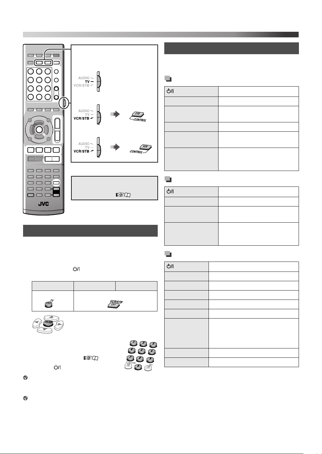
Operating external components
Set the remote control mode before
operation.
For TV
For STB
For VCR
Preparation
Make the audio/video input setting
before operation. ( 13)
Setting the manufacturer’s code
Before operating external components from the remote
control, set the manufacturer’s code.
1 Set the remote control mode (see above).
2 Press and hold for the target component
until the setting is finished.
For TV For STB For VCR
«Hold
3
4 Enter the manufacturer’s code.
See “Manufacturer’s code list” for the
manufacturer’s code. ( 30)
5 Release .
If there is more than one code listed
for the corresponding brand, try each one until you
enter the correct one.
Set the codes after replacing batteries of the remote
control.
«Hold
Operating external components
Set the remote control mode before operating each
external component (see the left column).
Operating the TV
TV
TV VOL +/– Adjusts the volume
TV/VIDEO Selects the input mode (either
CH +/– Changes the channels
1-10, 0, h 10
(100+)
TV RETURN Alternates between the
Operating the STB
VCR/STB
CH +/– Changes the channels
1-10, 0, h 10
(100+)
RETURN Alternates between the
Operating the VCR
VCR/STB
3 (play button) Starts playback
7 Stops playback
8 Pauses
y Fast-forwards the tape
1 Rewinds the tape
REC Press this button together with 3
CH +/– Changes the TV channels
0 - 9 Selects the TV channels
Turns the power on and off
TV or VIDEO)
Selects the channels
previously selected channel
and the current channel
Turns the power on and off
Selects the channels
previously selected channel
and the current channel
Turns the power on and off
(play button) to start recording or
together with 8 to enter recording-
pause.
29
Page 33

References
Manufacturer’s code list
TV
JVC 01* Magnavox 10 Samsung
Akai 02, 05 Mitsubishi 11, 33 Sanyo 05
Blaupunkt 03 Miver 03 Schneider 02, 05
Daewoo 10, 31, 32 Nokia 12, 34 Sharp 20, 39, 40
Fenner 04, 31, 32 Nordmende 13, 14, 18, 26, 27, 28 Sony 21, 22, 23, 24, 25
Fisher 05 Okano 09 Telefunken 13, 14, 18, 26, 27, 28
Grundig 06 Orion 15 Thomson 13, 14, 18, 26, 27, 28
Hitachi 07, 08 Panasonic 16, 17 Toshiba 29
Inno-Hit 09 Philips 10
Irradio 02, 05 Saba 13, 14, 18, 26, 27, 28
STB
Echostar 21 Jerrold
G.I.
Hamlin 15, 16, 17, 18 RCA 19 Zenith 11, 12
01*, 02, 03, 04, 05,
06, 07, 08
Pioneer 13, 14 Sony 20
01, 02, 03, 04, 05,
06, 07, 08
Scientific
Atlanta
10, 19, 32, 35, 36,
37, 38
09, 10
VCR
JVC 01* Hitachi 08, 09 Saba 17, 18, 19, 23, 31
Aiwa 02, 20 Loewe 05, 10, 11 Samsung 24, 25
Bell+Howell 03, 16 Magnavox 04, 05 Sanyo 03, 16
Blaupunkt 04 Mitsubishi 12, 13, 14, 15 Sharp 26, 27
CGM 03, 05, 16 Nokia 16 Siemens 07
Daewoo 34 Nordmende 17, 18, 19, 31 Sony 28, 29, 30, 35
DIGITAL 05 Orion 20 Telefunken 17, 18, 19, 31, 32
Fisher 03, 16 Panasonic 21 Toshiba 33
G.E 06 Philips 05, 22
Grundig 07 Phonola 05
* Initial setting
Manufacturers’ codes are subject to change without notice.
30
Page 34

References
Messages and icons shown on the TV
CANNOT PLAY
THIS DEVICE
CANNOT PLAY
THIS DISC
NO DISC
NO USB
DEVICE
NOT SUPPORT The file cannot be played back.
NOW READING Reading the disc/file information
OPEN/CLOSE Opening or closing the disc tray
READING
INDEX...
REGION CODE
ERROR!
RESTRICTED
DEVICE
The operation is unacceptable.
Playback
Pause
Fast-forward/fast-reverse
Forward/reverse slow-motion playback
The scene contains multi-audio languages.
The scene contains multi-subtitle
languages.
The scene contains multi-angle views.
An unplayable USB mass storage
class device is connected.
An unplayable disc is loaded.
No disc or an unfinalized disc is
loaded.
No USB mass storage class
device is loaded.
Reading the DivX file
The Region Code of the DVD
Video disc does not match the
code the System supports.
(3)
iPod is connected to the USB
MEMORY terminal.
Available surround modes
Surround mode for “S.SPK F”
AUTO SUR
(Auto Surround)
MOVIE
WIDE/2CH For 2-channel music sources
SUPER W
(Super Wide)
OFF (Off) Deactivates surround mode
Surround mode for “S.SPK R”
AUTO SUR
(Auto Surround)
MOVIE (Dolby Pro
Logic II Movie)
MUSIC (Dolby Pro
Logic II Music)
STADIUM
ALL ST
(All Channel
Stereo)
OFF (Off) Deactivates surround mode
Selects an appropriate
surround mode according to
the incoming signals
For movie or multi-channel
music sources
Reproduces broader sound
field
Selects an appropriate
surround mode according to
the incoming signals
For movie sources
For music sources
Adds clarity and spreads the
sound as if in an outdoor
stadium
Reproduces a larger stereo
sound field using all the
activated speakers
You can change the setting so that the on-screen
guide icons do not appear on the TV. ( 24)
31
Page 35

Language code list
AA Afar GD Scots Gaelic MI Maori SN Shona
AB Abkhazian GL Galician MK Macedonian SO Somali
AF Afrikaans GN Guarani ML Malayalam SQ Albanian
AM Ameharic GU Gujarati MN Mongolian SR Serbian
AR Arabic HA Hausa MO Moldavian SS Siswati
AS Assamese HI Hindi MR Marathi ST Sesotho
AY Aymara HR Croatian MS Malay (MAY) SU Sundanese
AZ Azerbaijani HY Armenian MT Maltese SV Swedish
BA Bashkir IA Interlingua MY Burmese SW Swahili
BE Byelorussian IE Interlingue NA Nauru TA Tamil
BG Bulgarian IK Inupiak NE Nepali TE Telugu
BH Bihari IN Indonesian NL Dutch TG Tajik
BI Bislama IS Icelandic NO Norwegian TH Thai
BN Bengali, Bangla IW Hebrew OC Occitan TI Tigrinya
BO Tibetan JI Yiddish OM (Afan) Oromo TK Turkmen
BR Breton JW Javanese OR Oriya TL Tagalog
CA Catalan KA Georgian PA Panjabi TN Setswana
CO Corsican KK Kazakh PS Pashto, Pushto TO Tonga
CY Welsh KL Greenlandic PT Portuguese TR Turkish
DA Danish KM Cambodian QU Quechua TS Tsonga
DZ Bhutani KN Kannada RM Rhaeto-Romance TT Tatar
EL Greek KO Korean (KOR) RN Kirundi TW Twi
EO Esperanto KS Kashmiri RO Rumanian UK Ukrainian
ET Estonian KU Kurdish RW Kinyarwanda UR Urdu
EU Basque KY Kirghiz SA Sanskrit UZ Uzbek
FA Persian LA Latin SD Sindhi VI Vietnamese
FI Finnish LN Lingala SG Sangho VO Volapuk
FJ Fiji LO Laothian SH Serbo-Croatian WO Wolof
FO Faroese LT Lithuanian SI Singhalese XH Xhosa
FY Frisian LV Latvian, Lettish SL Slovenian YO Yoruba
GA Irish MG Malagasy SM Samoan ZU Zulu
32
Page 36

References
Troubleshooting
Power does not come on.
ZThe power plug is not inserted securely. Plug it in
securely.
Unable to operate the System from the remote
control.
ZThe path between the remote control and the remote
sensor on the center unit is blocked.
ZThe batteries are exhausted.
No sound is heard.
ZThe speaker connections or audio cord connections are
incorrect or loose. ( 6, 8)
ZHeadphones are connected.
The sound is distorted.
ZThe speaker layout ( 5) does not match the speaker
position mode ( 11).
No picture appears on the TV.
ZThe video cord connections are incorrect or loose.
(7, 8)
The picture does not fit the TV.
ZThe monitor type is not set correctly. ( 23)
No picture is displayed on the TV, the picture is
blurred, or the picture is divided into two parts.
ZThe scanning mode is set to the progressive mode even
though the TV connected to the System does not support
progressive video input. ( 12)
ZInappropriate scanning mode is selected. ( 12)
No picture is displayed on the TV or no sound
comes out through the HDMI connection.
ZThe connected TV is not HDCP-compatible. (“HDCP
ERR” appears on the display.)
ZDisconnect the HDMI cable and connect it again, or use
a shorter cable.
Video and audio are distorted.
ZThe disc is scratched or dirty.
ZAudio/video files have not been properly copied on to the
USB mass storage class device.
ZA VCR is connected between the center unit and the TV.
Connect the center unit and TV directly. ( 7, 8)
VCD/SVCD operation cannot be performed.
ZSome functions do not work for VCDs/SVCDs when the
PBC function is used.
No sound is heard or no picture appears while
playing the external components, or the video and
audio do not match.
ZThe selected audio or video input is not appropriate.
Select the audio/video input to match the component
connected. ( 13)
The iPod does not play even though “CONNECT”
appears on the display.
ZThe battery of the iPod is exhausted. Leave the iPod
connected for at least 10 minutes.
The iPod cannot be operated from the System.
ZThe iPod battery charge function is deactivated.
( 14)
ZThe iPod is not compatible with the System. Check the
compatibility. ( 3)
iPod is not charged.
ZThe source is not “IPod.”
ZThe iPod battery charge function is deactivated.
( 14)
The broadcast is hard to hear because of noise.
ZAntenna connections are incorrect or loose. ( 7)
ZThe AM (MW) loop antenna is too close to the System.
ZThe FM Antenna is not properly extended and positioned.
(7)
Attaching the dock adapter to the docking connection
To detach the dock adapter
from the docking station:
Dock adapter (supplied
for iPod or separately
purchased)
Docking station
Push the slot then pull up to
remove the dock adapter.
33
Disconnect the docking station from the
center unit when attaching/detaching the
dock adapter.
Take care not to damage the terminal on
the docking station when attaching/
detaching the dock adapter.
Page 37

Specifications
Center unit (XV-THD51)
Output power
Front:
140 W per channel, RMS at 4 Ω at 1 kHz, with 10% total
harmonic distortion.
Center:
130 W, RMS at 4 Ω at 1 kHz, with 10% total harmonic
distortion.
Surround:
130 W per channel, RMS at 4 Ω at 1 kHz, with 10% total
harmonic distortion.
Subwoofer:
140 W, RMS at 4 Ω at 100 Hz, with 10% total harmonic
distortion.
Audio section
Digital Input*
DIGITAL IN
OPTICAL: –21 dBm to –15 dBm (660 nm
±30 nm)
Analog Input: AUDIO IN
Video section
Video System: PAL
Horizontal Resolution: 500 lines
Signal-to-Noise Ratio: 54 dB
(Composite signal when “RGB” is selected)
Video Output Level
(AV—Scart)
Composite video: 1.0 V(p-p)/75 Ω
Y: 1.0 V(p-p)/75 Ω
C: 0.3 V(p-p)/75 Ω
RGB: 0.7 V(p-p)/75 Ω
(VIDEO OUT)
Component (Y): 1.0 V(p-p)/75 Ω
(P
B/PR): 0.7 V(p-p)/75 Ω
Video Input Sensitivity/Impedance (VIDEO IN)
Composite: 1.0 V(p-p)/75 Ω
S-video (Y): 1.0 V(p-p)/75 Ω
(C): 0.3 V(p-p)/75 Ω
HDMI
HDMI Output (MONITOR OUT):
576p/720p/1080i
USB storage
USB Specification: Compatible with USB 2.0 Full
Speed
Compatible Device: Mass Storage Class
Compatible File System: FAT16, FAT32
Bus Power Supply: Max. 500 mA
Tuner section
Tuner Range
FM: 87.50 MHz to 108.00 MHz
AM (MW): 522 kHz to 1 629 kHz
General
Power Requirements: AC 230 V , 50 Hz
Power Consumption: 160 W (during operation)
1.0 W (in standby mode)
Dimensions (W
Mass: 6.8 kg
Corresponding to Linear PCM, Dolby Digital, and DTS
*
(with sampling frequency — 32 kHz, 44.1 kHz, 48 kHz)
× H × D): 435 mm ×115 mm ×270 mm
Subwoofer (SP-THD51W)
Type: Bass-Reflex Type
Speaker: 16 cm cone
Power Handling Capacity: 140 W
Impedance: 4 Ω
Frequency Range: 30 Hz to 200 Hz
Sound Pressure Level: 72 dB/W
Dimensions (W
Mass: 4.9 kg
× H × D): 214 mm × 296 mm × 329 mm
× 1
•
m
34
Page 38

References
Front speakers (SP-THD51F)
Type:
1-Way 2-Speaker Bass-Reflex Type (Magnetically
Shielded Type)
Speaker: 5.5 cm cone
Power Handling Capacity: 140 W
Impedance: 4 Ω
Frequency Range: 100 Hz to 20 000 Hz
Sound Pressure Level: 80 dB/W
Dimensions (W
Without the stand: 180 mm
With the stand: 180 mm
Mass: 0.93 kg each (with the stand)
× H × D):
× 2
•
m
× 73 mm × 91 mm
× 119 mm × 91 mm
Center surround speaker (SP-THD51C)
Type:
Center:
1-Way 2-Speaker Bass-Reflex Type (Magnetically
Shielded Type)
Surround Left:
1-Way 2-Speaker Bass-Reflex Type (Magnetically
Shielded Type)
Surround Right:
1-Way 2-Speaker Bass-Reflex Type (Magnetically
Shielded Type)
Speaker:
Center: 5.5 cm cone
Surround Left: 5.5 cm cone
Surround Right: 5.5 cm cone
Power Handling Capacity:
Center: 140 W
Surround Left: 140 W
Surround Right: 140 W
Impedance:
Center: 4 Ω
Surround Left: 4 Ω
Surround Right: 4 Ω
Frequency Range:
Center: 100 Hz to 20 000 Hz
Surround Left: 100 Hz to 20 000 Hz
Surround Right: 100 Hz to 20 000 Hz
Sound Pressure Level:
Center: 80 dB/W
Surround Left: 80 dB/W
Surround Right: 80 dB/W
Dimensions (W
Mass: 2.1 kg
× H × D): 435 mm × 74 mm × 91 mm
× 2
× 2
× 2
•
m
•
m
•
m
Dimensions of the wall-mount attachment for the
front and center surround speakers:
SP-THD51F
72.4
4
2
SP-THD51C
333
4
Unit: mm
Designs and specifications are subject to change without
notice.
35
Page 39

• This product incorporates copyright protection
technology that is protected by U.S. patents and other
intellectual property rights. Use of this copyright
protection technology must be authorized by
Macrovision, and is intended for home and other
limited viewing uses only unless otherwise authorized
by Macrovision. Reverse engineering or disassembly is
prohibited.
• “CONSUMERS SHOULD NOTE THAT NOT ALL
HIGH DEFINITION TELEVISION SETS ARE
FULLY COMPATIBLE WITH THIS PRODUCT
AND MAY CAUSE ARTIFACTS TO BE
DISPLAYED IN THE PICTURE. IN CASE OF 525
OR 625 PROGRESSIVE SCAN PICTURE
PROBLEMS, IT IS RECOMMENDED THAT THE
USER SWITCH THE CONNECTION TO THE
‘STANDARD DEFINITION’ OUTPUT.
IF THERE ARE QUESTIONS REGARDING OUR
TV SET COMPATIBILITY WITH THIS MODEL
525p AND 625p DVD PLAYER, PLEASE
CONTACT OUR CUSTOMER SERVICE CENTER.”
• USE OF THIS PRODUCT IN ANY MANNER THAT
COMPLIES WITH THE MPEG-4 VISUAL
STANDARD IS PROHIBITED, EXCEPT FOR USE
BY A CONSUMER ENGAGING IN PERSONAL
AND NON-COMMERCIAL ACTIVITIES.
• DivX, DivX Ultra Certified, and associated logos are
trademarks of DivX, Inc. and are used under license.
®
• Official DivX
• Plays all versions of DivX
Ultra Certified product
®
video (including DivX® 6)
with enhanced playback of DivX® media files and the
DivX® Media Format
• Microsoft and Windows Media are either registered
trademarks or trademarks of Microsoft Corporation in
the United States and/or other countries.
• DVD Logo is a trademark of DVD Format/Logo
Licensing Corporation.
• Manufactured under license from Dolby Laboratories.
“Dolby”, “Pro Logic”, “MLP Lossless”, and the
double-D symbol are trademarks of Dolby
Laboratories.
• “DTS” and “DTS Digital Surround” are registered
trademarks of DTS, Inc.
• HDMI, the HDMI logo and High-Definition
Multimedia Interface are trademarks or registered
trademarks of HDMI Licensing LLC.
• HDCP is the abbreviation of “High-bandwidth Digital
Content Protection,” and is the high-reliable copy
control technology licensed by Digital Content
Protection, LLC.
36
Page 40

SAFETY INSTRUCTIONS
“SOME DOS AND DON’TS ON THE SAFE USE OF EQUIPMENT”
This equipment has been designed and manufactured to meet international safety standards but, like any
electrical equipment, care must be taken if you are to obtain the best results and safety is to be assured.
Do read the operating instructions before you attempt to use the equipment.
Do ensure that all electrical connections (including the mains plug, extension leads and interconnections
between pieces of equipment) are properly made and in accordance with the manufacturer’s instructions.
Switch off and withdraw the mains plug when making or changing connections.
Do consult your dealer if you are ever in doubt about the installation, operation or safety of your equipment.
Do be careful with glass panels or doors on equipment.
DON’T continue to operate the equipment if you are in any doubt about it working normally, or if it is
damaged in any way—switch off, withdraw the mains plug and consult your dealer.
DON’T remove any fixed cover as this may expose dangerous voltages.
DON’T leave equipment switched on when it is unattended unless it is specifically stated that it is designed
for unattended operation or has a standby mode.
Switch off using the switch on the equipment and make sure that your family know how to do this.
Special arrangements may need to be made for infirm or handicapped people.
DON’T use equipment such as personal stereos or radios so that you are distracted from the requirements of
traffic safety. It is illegal to watch television whilst driving.
DON’T listen to headphones at high volume as such use can permanently damage your hearing.
DON’T obstruct the ventilation of the equipment, for example with curtains or soft furnishings.
Overheating will cause damage and shorten the life of the equipment.
DON’T use makeshift stands and NEVER fix legs with wood screws—to ensure complete safety always fit
the manufacturer’s approved stand or legs with the fixings provided according to the instructions.
DON’T allow electrical equipment to be exposed to rain or moisture.
ABOVE ALL
—NEVER let anyone, especially children, push anything into holes, slots or any other opening in the case
—this could result in a fatal electrical shock.;
—NEVER guess or take chances with electrical equipment of any kind—it is better to be safe than sorry!
E43486-340B
TH-D51
DVD DIGITAL CINEMA SYSTEM
EN
© 2007 Victor Company of Japan, Limited
0807RYMMDWJMM
 Loading...