

Page 1
ENGLISH
JVC
SP-PW3000
POWERED SUBWOOFER
SUBWOOFER MIT EINGEBAUTEM VERSTÄRKER
SUPER WOOFER AMPLIFIÉ
SUBWOOFER MET VERSTERKING
H“
Connecting cord (supplied)
AnschluBkabel (im Lieferumfang enthalten)
UX-1000/1500R/2000R
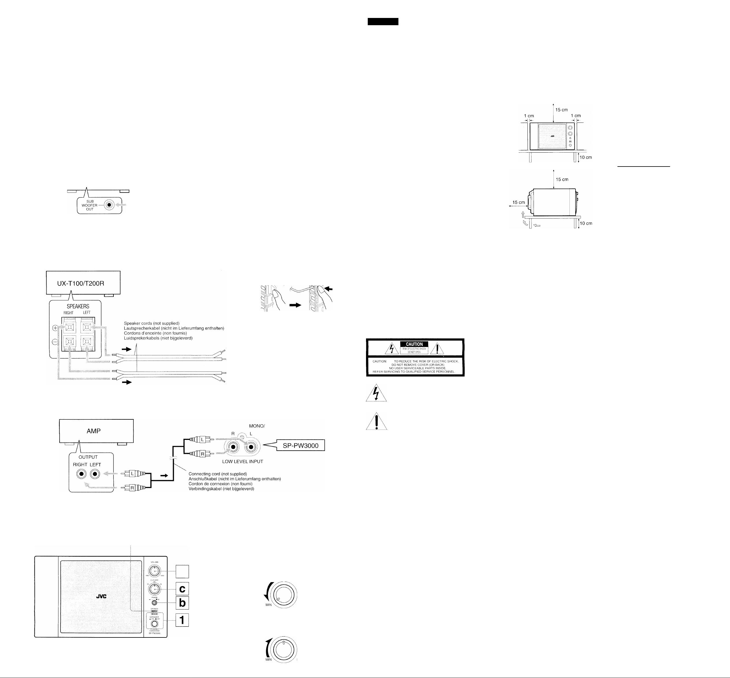
Connect the speaker cords in parallel to the speaker terminals on the Micro Component System.
Schließen Sie die Lautsprecherkabel parallel an die Lautsprecheranschlüsse am Mikrokomponentensystem an.
Connecter les cordons d’enceinte en parallèle aux prises d’enceinte de la microchaîne.
Sluit de luidsprekerkabels parallel aan op de luidsprekeraansluitpunfen op het Mikrokomponentensysteem.
Cordon de connexion (fourni)
Verbindingskabel (bijgeleverd)
■<103=
2 4
VNN9330-691C
[B, E, G, EN]
MONO/
R
LOW LEVEL INPUT
L
HIGH LEVEL INPUT
1
,CD
0997MNMMDWJSC
EN, GE, FR, NL, SP, IT, SW, Fl, DA
SP-PW3000
<¡ SP-
©POWER
—-ON M.OFF
PW3000
O
VOLUME
Thank you for purchasing this JVC product. Please
read these instructions carefully before starting
operation to be sure to obtain optimum performance
and a longer service life from the unit.
IMPORTANT (In the United Kingdom)
Mains Supply (AC 230VT;, 50 Hz only)
DO NOT cut off the mains plug from this equipment.
If the plug fitted is not suitable for the power points
in your home or the cable is too short to reach a
power point, then obtain an appropriate safety
approved extension lead or consult your dealer.
BE SURE to replace the fuse only with an identical
approved type, as originally fitted, and to replace
the fuse cover.
If nonetheless the mains plug is cut off ensure to
remove the fuse and dispose of the plug
immediately, to avoid a possible shock hazard by
inadvertant connection to the mains supply.
IMPORTANT
DO NOT make any connection to the terminal which
is marked with the letter E or by the safety earth
symbol or coloured green or green-and-yellow.
The wires in the mains lead on this product are
coloured in accordance with the following code:
Blue to N (Neutral) or Black
Brown to L (Live) or Red
As these colours may not correspond with the
coloured markings identifying the terminals in your
plug proceed as follows:
The wire which is coloured blue must be connected
to the terminal which is marked with the letter N or
coloured black.
The wire which is coloured brown must be
connected to the terminal which is marked with the
letter L or coloured red.
IF IN DOUBT - CONSULT A COMPETENT
ELECTRICIAN.
WARNING:
TO REDUCE THE RISK OF FIRE OR ELECTRIC
SHOCK, DO NOT EXPOSE THIS APPLIANCE TO
RAIN OR MOISTURE.
The lightning flash with arrowhead symbol,
within an equilateral triangle is intended to
alert the user to the presence of uninsulated
"dangerous voltage" within the product's
enclosure that may be of sufficient
magnitude to constitute a risk of electric
shock to persons.
The exclamation point within an equilateral
triangle is intended to alert the user to the
presence of important operating and
maintenance (servicing) instructions in the
literature accompanying the appliance.
SAFETY PRECAUTIONS
Prevention of Electric Shocks, Fire Hazards and
Damage
1. Do not handle the power cord with wet hands.
2. When unplugging from the wall outlet, always
grasp and pull the plug, not the power cord.
3. Consult your nearest dealer when damage,
disconnection, or contact failure affects the cord.
4. Do not bend the cord severely, or pull or twist it.
5. Do not modify the power cord in any manner.
6. To avoid accidents, do not remove screws to
disassemble the unit and do not touch anything
inside the unit.
7. Do not insert any metallic objects into the unit.
8. Unplug the power cord when there is a possibility
of lightning.
9. If water gets inside the unit, unplug the power cord
from the outlet and consult your dealer.
10. Do not block the unit’s ventilation holes that allow
heat to escape.
11. Do not install the unit in a badly ventilated place.
12. Do not place the unit upside down.
13. Be sure to unplug the power cord from the outlet
when going out or when the unit is not in use for
an extended period of time.
Caution: Proper Ventilation
To avoid risk of electric shock and fire, and to prevent
damage, locate the apparatus as follows:
1. Front:
No obstructions and open spacing.
2. Sides/Top/Back:
No obstructions should be placed in the areas
shown by the dimensions below.
3. Bottom:
Place on the level surface. Maintain an adequate
air path for ventilation by placing on a stand with a
height of 10 cm or more.
HANDLING PRECAUTIONS
Do not use this unit in direct sunlight where it would
be exposed to high temperatures above 40°C (104°F).
1. Avoid installing in the following places
• Where it could be subject to vibrations.
• Where it is excessively humid, such as in a
bathroom.
• Where it could be magnetized by a magnet or
speaker.
2. Condensation
In the following cases, condensation may occur in
the unit, in which case the unit may not operate
correctly.
• In a room where a heater has just been switched
on.
• In a place where there is smoke or high humidity.
• When the unit is moved directly from a cold to a
warm room.
In these cases, set the © POWER button to OFF
and wait 1 or 2 hours before use.
3. Volume setting
CDs/MDs produce very little noise compared with
analogue sources. If the volume level is adjusted
for these sources, the speakers may be damaged
by the sudden increase of output level. Therefore,
lower the volume before operation and adjust it
as required during play.
4. Keep this unit away from your TV
When this unit is used near a TV, the TV picture
could be distorted. If this happens, move this unit
away from the TV. If this does not correct the
situation, avoid using this unit when the TV is
turned on.
5. Cleaning the cabinet
If the cabinet gets dirty, wipe it with a soft, dry cloth.
Never use benzine or thinner as these could
damage the surface finish.
CONNECTIONS:
Plug the AC power cord after all connections are
complete.
□ When connecting JVC Ultra Micro Component
System (UX-1000/1500R/2000R)
Q When connecting JVC Micro Component System
(UX-T100/T200R etc.)
Note: No sound comes out of this speaker if you
connect the headphones to your Micro Component
System.
B When connecting a Preamplifier of any
manufacturers’
CAUTION: DO NOT use the REC OUT jacks of
the preamplifier to connect this speaker.
OPERATIONS: B
__________
Presetting the Volume
You need to preset the volume level of this speaker
to match those of the other speakers.
Once you preset the volume level, it is stored as your
reference level and the volume level of this speaker
will be able to automatically change as the volume
level of the stereo system changes.
iTJ Turn on the power.
The POWER indicator lights up.
[2] Set the volume to “MIN.”
[3] Adjust the volume of the connected stereo system
to your listening level.
[4] Adjust the volume to balance it with those of the
other speakers.
To turn off this speaker, press the ® POWER button
again so that the POWER indicator goes off. (The
indicator may not go off ¡mediately.)
About the OPERATE Indicator (@)
The OPERATE indicator lights up while sound signals
are coming into this speaker.
Adding the Richness to the Bass
(PHASE: E)
Normally set the PHASE button in the “M -i-” position.
If you want to add the richness more to the bass,
press the PHASE button to set it either in the
position or the “M +” position, whichever can add the
richness to the bass.
Cutting Off the Higher Frequencies
(CUT OFF: 0)
Set the CUT OFF selector to the position giving you
the preferable sound, according to the other speaker
system used and to the played back music.
Automatic Operating Status On/Off
To save energy, this speaker enters the standby mode
(the OPERATE indicator goes off) if no (or very weak)
sound signals come into this unit for a while.
When sound signals come in again (the OPERATE
indicator comes on), this speaker enters the operating
mode and reproduces the sounds.
Spedficotions
Model: Powered subwoofer
Speaker unit: Woofer 10 cm (4 Q) x 2
Frequency response: 40- 100 Hz
Output sound pressure level: 81 dB/W»m
Input terminals:
LOW LEVEL: 12 mV/56 kQ
HIGH LEVEL: 230 mV/430 Q
Output power: 25 W -i- 25 W (Max.)
Power requirements; AC 230 V%, 50 Hz
Power consumptions: 30 W
Dimensions; Approx. 258 x 158 x 294 mm (W/H/D)
Mass: Approx. 5.8 kg
* THD: Total Harmonic Distortion
Design and specifications are subject to change
without prior notice.
Rated impedance: 4 Q
20 W-k20W(10%THD*)
VOLUME
 Loading...