

Page 1

SERVICE MANUAL
REMOTE CONTROL UNIT
RM-P210U/RM-P210E
RM-P210U/RM-P210E
CALLTALLY
INTERCOM
LEVEL
FULL AUTO F1
BARS
MENU/SHUTTER GAIN
SHUTTER
F2
GAIN
F3
VARIABLE
SHUTTER
PUSH-ON
DOWN UP
PUSH-ON
DOWN UP
F4
MENU
STEP
HIGH
LOW
PAINT AUTO
MID
WHITE MASTER BLACK
REMOTE CONTROL UNIT RM-P210
W.BAL
B
A
BR
PRESET
AUTO
MANU
IRIS
CLOSE OPEN
POWER
I
O
VICTOR COMPANY OF JAPAN, LIMITED
Printed in Japan
(V.P.) A.I
No. 60136
100% recycled paper
COPYRIGHT ' 2001 VICTOR COMPANY OF JAPAN, LTD.
No. 60136
April 2001
Page 2

TABLE OF CONTENTS
IMPORTANT SAFETY PRECAUTIONS
■
INSTRUCTIONS
■
1. SERVICE CAUTIONS AND DISASSEMBLY ............................................................................................................ 1-1
1.1 REMOVAL OF EXTERNAL COVER..................................................................................................................... 1-1
1.2 FUNCTIONS AND SETTINGS OF INTERNAL SWITCHES .................................................................................. 1-2
1.3 ADJUSTMENT AND CHECK MODES ................................................................................................................ 1-3
2. ELECTRICAL ADJUSTMENT .................................................................................................................................... 2-1
2.1 INSTRUMENTS REQUIRED FOR ADJUSTMENTS, THEIR SETUPS ................................................................. 2-1
2.2 ADJUSTMENT MODE ........................................................................................................................................ 2-2
2.3 TRANSMIT VOLTAGE ADJUSTMENT ................................................................................................................ 2-3
2.4 COMPOSITE SIGNAL OUTPUT ADJUSTMENT ................................................................................................. 2-3
2.5 COMPONENT/RGB SIGNAL OUTPUT ADJUSTMENT ...................................................................................... 2-4
2.6 INTERCOM LEVEL ADJUSTMENT .................................................................................................................... 2-5
3. CHARTS AND DIGRAMS .......................................................................................................................................... 3-1
3.1 MAIN/FR1/FR2/CC/SUB1 BOARD SCHEMATIC DIAGRAM 01 / 02 / 03 / 04 / 05 ................................. 3-1
3.2 MAIN CIRCUIT BOARD 01 .............................................................................................................................. 3-2
3.3 FR1 CIRCUIT BOARD 02 ................................................................................................................................. 3-2
3.4 FR2 CIRCUIT BOARD 03 ................................................................................................................................. 3-2
3.5 CC CIRCUIT BOARD 04 ................................................................................................................................... 3-2
3.6 SUB1 CIRCUIT BOARD 05 ............................................................................................................................... 3-2
3.7 IC BLOCK DIAGRAM.......................................................................................................................................... 3-3
4. EXPLODED VIEW AND PARTS LIST ....................................................................................................................... 4-1
4.1 RM-P210 ASSEMBLY M2 ................................................................................................................................. 4-1
5. ELECTRICAL PARTS LIST ......................................................................................................................................... 5-1
5.1 MAIN BOARD ASSEMBLY PARTS LIST 01..................................................................................................... 5-2
5.2 FR1 BOARD ASSEMBLY PARTS LIST 02........................................................................................................ 5-7
5.3 FR2 BOARD ASSEMBLY PARTS LIST 03........................................................................................................ 5-8
5.4 CC BOARD ASSEMBLY PARTS LIST 04 ......................................................................................................... 5-8
5.5 SUB1 BOARD ASSEMBLY PARTS LIST 05..................................................................................................... 5-8
6. PACKING ................................................................................................................................................................... 6-1
6.1 PACKING ASSEMBLY M1................................................................................................................................ 6-1
Page 3
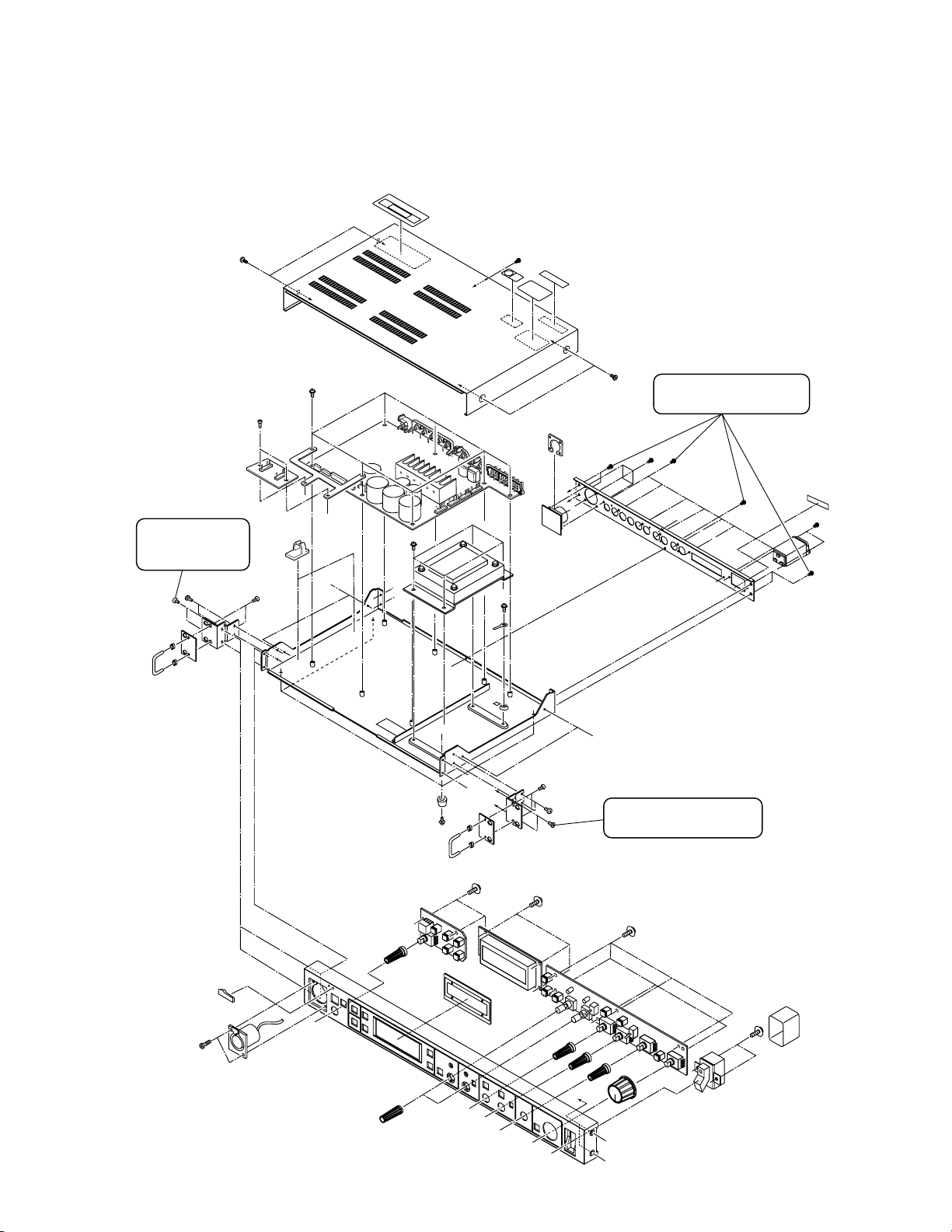
SERVICE CAUTIONS AND DISASSEMBLY
1.1 REMOVAL OF EXTERNAL COVER
SECTION 1
‘‘D’’
Remove these 2
screws to remove
the front panel.
‘‘D’’
‘‘F’’
‘‘E’’
‘‘E’’
Remove these 12 screws
to remove the rear panel.
‘‘C’’
‘‘C’’
‘‘D’’
‘‘C’’
‘‘C’’
‘‘E’’
‘‘F’’
‘‘B’’
‘‘A’’
‘‘B’’
‘‘A’’
Remove these 2 screws
to remove the front panel.
‘‘B’’
‘‘A’’
‘‘A’’
1-1
Page 4
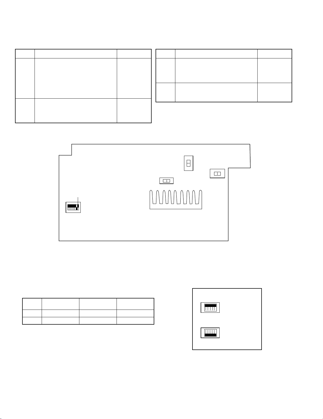
1.2 FUNCTIONS AND SETTINGS OF INTERNAL SWITCHES
1.2.1 MAIN Board
Symbol Function Factory Setting
S1 U model:
8-segment DIP switch to be set
according to the destination type.
No. 1 ON : PAL. OFF: NTSC
No. 2 ON: Japan OFF: USA
Nos. 3 to 8: Not used. (Set to OFF.)
S601 U model: M
Tally input M/V switch
M: Make contact (ON when shorted)
V: Voltage (ON when AC or DC is applied)
No. 1 OFF
No. 2 OFF
E model:
No. 1 ON
No. 2 OFF
E model: V
MAIN Board (Rear Side)
No.1
OFF
Symbol Function Factory Setting
S602 U model: RTS
S603 DYNAMICIntercom headset microphone
Intercom headset 2W/RTS switch.
2W: 2-wire intercom
RTS: RTS intercom
DYNAMIC/CARBON switch.
E model: 2W
RTS
S601S602
MV
S603
2W
CARBONDYNAMIC
ON
S1
1.2.2 CC Board
Set switches S35 and S36 according to the connected camera cable.
Symbol
S35
S36
Sony Cable
CCZ-A100 (100 m)
All ON
All OFF
JVC Cable Factory Setting
All OFF
All ON
All OFF
All ON
S35
S36
CC Board
ON
OFF
ON
OFF
1-2
Page 5

*HOW TO SET IT FOR USING SONY CABLE CCZ-A100.
Sony cable can be used by changing the setting as below only when RM-P210 is connected with GY-DV550. Sony has many type of
the cables but we can not check all the cable. Please do not use other than CCZ-A100.
1. GY-DV550 setting
Change the connection of the connector CN77 to CN83 on 56 CN board.
2. RM-P210 setting
(1) Change the setting of the switch on CC board
a) S35 : All switch have to be set to ON (UP side).
CN77
b) S36 : All switch have to be set to OFF (DOWN side).
(2) Re-adjustment of the transmit voltage (see “2.3 TRANSMIT VOLTAGE
ADJUSTMENT)
After re-adjustment, check the voltage between pin A and pin B in 26P
connector of RM-P210. It MUST be less than 15V. If it was more than
15V, adjustment of the b) and c) (+17V and +19V adjustment) have to
re-adjust to 15V from 16V.
a) +15V supply adjustment : adjust to 15 ± 0.2V
DC
CN83
b) +17V supply adjustment : adjust to 16 ± 0.2VDC
c) +19V supply adjustment : adjust to 16 ± 0.2VDC
Note 1: If the Voltage was not readjusted the View Finder will be damaged due to the heating problem.
Note 2: Difference between Sony cable and JVC cable is the impedance.
JVC cable: 1.3 Ohm Sony cable: 0.8 Ohm.
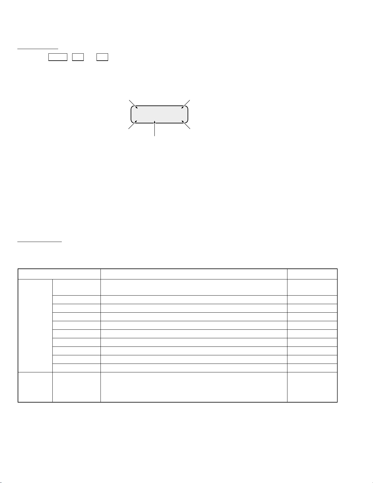
1.3 ADJUSTMENT AND CHECK MODES
1.3.1 Starting the Service Modes and Front Panel Check Mode
The RM-P210 incorporates the following service modes for use in servicing. Each of the service modes can be entered at the same
time as turning the RM-P210 ON and continues until it is turned OFF. Communications with the camera are not performed except in
the normal mode.
The following table shows the names of the modes and their details.
Mode Name Startup Method Contents
Normal
Data Clear
Any other method than those described below.
Hold FULL AUTO , BARS and IRIS buttons
This mode starts in normal operation by user.
All EEPROM and SRAM data are initialized.
simultaneously while turning power ON.
Hardware Check
Adjustment
Hold CALL , F1 and F2 buttons
simultaneously while turning power ON.
Hold MENU , F3 and F4 buttons
Displays the program version.
Check of LEDs, SW, VR, JOG dials, etc.
For adjustments of supply voltage and cable length.
simultaneously while turning power ON.
1.3.2 Data Clear Mode
Startup method
Hold the FULL AUTO , BARS and IRIS buttons simultaneously while press the POWER switch.
Operation Details
When the unit is started in the Data Clear mode, all EEPROM and SRAM data is initialized and the following message appears in
the LCD. After this, all operations are inhibited.
DATA C L EARED ! !
1-3
Page 6
1.3.3 Hardware Check Mode
Startup method
Hold the CALL , F1 and F2 buttons simultaneously while pressing the POWER switch.
The LEDs other than TALLY lights.
When the unit is turned ON, the LCD shows the program number and software version as shown below (initial display).
Program No. EEPROM check result OK/NG
CV1∗3.5∗9
∗ <UE>EPSRROAMMOOKK
Version
SRAM check result OK/NG
Model type
Japan: I
USA: U
Europe: E
The LCD also shows the results, either OK or NG, of the EEPROM and SRAM checking executed at the moment the unit is turned
ON.
The SRAM check consists of verifying the data retention status at the moment the unit is turned ON. The SRAM is backed up by
a super-capacitor. Therefore, “NG” is displayed even when the back-up power supply is down.
The initial display above disappears when any of the operations accompanied with the LCD display, described on the next page, is
executed.
To view the initial display again, press the CALL button.
Operation details
Turning a button or terminal ON or OFF causes an operation as described below. The switches can be checked by turning the LEDs
on or off. All LEDs are turned off at the moment the unit is turned ON
Check Point Check Details Remark
Each press of this button should turn the LED on/off and the initial display
appears when it is on.
Each press of this button should turn the LED on/off.
Each press of this button should turn the LED on/off.
Each press of one of these buttons should turn the corresponding LED on/off.
Each press of this button should turn the LED on/off.
Each press should turn the LED on/off.
Each press should turn the LED on/off.
Each press of this button should turn the LED on/off.
Each press of this button should turn the LED on/off.
Each press of this button should turn the LED on/off.
The green LED should light when TALLY PVW on the rear panel is Active
and the red should light when TALLY PGM is Active. Only the red LED
should light when both tallies are Active.
No LED should light when no tallies are Active.
Buttons/
LEDs
Rear-panel
terminal/
LED
CALL
FULL AUTO
BARS
F1 to F4
MENU
SHUTTER JOG
V.GAIN JOG
PAINT (WHITE)
AUTO (WHITE)
IRIS
TALLY
1-4
Page 7

With the checking of VR, JOG dials and switches, operating a control causes information to be displayed on the LCD. The LCD
display is retained until other information is displayed on the LCD. However, pressing the CALL button displays the initial display.
Check Point Check DetailsLCD Display Remark
Turn this VR and confirm that data varies between 0 and 255.
Turning clockwise should increase the value.
This VR also controls the LCD contrast. It is Normal at the
center. Turning the VR clockwise should increase contrast
and counter-clockwise should decrease it. The LCD back light
should be OFF at the most clockwise position.
IRIS
IRIS
128
VR
JOG
SW
MASTER
BLACK
WHITE Bch
WHITE Rch
SHUTTER JOG
V.GAIN JOG
W.BAL
STEP GAIN
M.BLACK (SC FINE)
128
WHITE Bch(C)
128
WHITE Rch(Y)
128
SHUT JOG(LENGTH)
20M
V.GAIN JOG(SC)
0°
W.BAL(ASPECT)
PRE(4:3)
GAIN(VOLT)
LOW(15V)
Turn this VR and confirm that data varies between 0 and 255.
Turning it clockwise should increase the value.
This VR also controls the SC FINE data output.
Turn this VR and confirm that data varies between 0 and 255.
Turning it clockwise should increase the value.
This VR also controls the LENGTH HF data output
Turn this VR and confirm that data varies between 0 and 255.
Turning it clockwise should increase the value.
This VR also controls the LENGTH Y data output
Turn this JOG and confirm that data is switched to 5M, 20M,
50M and 100M. Turning it clockwise should increase the
value.
The initial value when the unit is turned ON is 20M.
This JOG also checks the JOG rotation and JOG hardware
when LENGTH is selected in addition to SHUTTER JOG
check.
Turn JOG and confirm that data is switched to 0°, 90°, 180°
and 270°. Turning clockwise should increase the value.
The initial value when the unit is turned ON is 0°.
This JOG also checks the JOG rotation and JOG hardware
when SC COARSE is selected in addition to V.GAIN JOG
check.
Operate this SW and confirm that A, B and PRE are displayed
correctly when the SW is in the corresponding position.
This SW should also vary ASPECT internally: When A (16:9),
B (Letter Box) and PRE (4:3) are displayed, the internal mode
should vary accordingly.
Operate this SW and confirm that LOW, MID and HIGH are
displayed correctly when the SW is in the corresponding
position.
This SW should also vary the supply voltage to the camera
internally: When LOW (15 V), MID (17 V) and HIGH (19 V) are
displayed, the internal voltage should vary accordingly.
When the unit is
turned ON, 15 V is
output regardless
of the position of
this SW, until this
SW is changed to
another position.
DIP
SW
SW 1 to 8
DIP SW12345678
LLLLLLLLL
Set each SW to ON and OFF and confirm that the
corresponding display changes to H (ON) or L (OFF).
1.3.4 Adjustment Mode
The Adjustment mode is detailed in the description of the adjustment procedures. Please see section 2.2.
1-5
Page 8

SECTION 2
HGCCPVWPGM
TALLY
AC~IN AC100V 50V/60Hz
INTERCOM AUX VIDEO INPUT GENLOCK INPUT VIDEO OUTPUT Y/C OUT
CAMERA CABLE
R/R-Y B/B-Y
COMPOSITE VIDEO
G/Y
Camera cable
VC-P112 (20 m)
Intercom
KA-310U or equivalent
Intercom
KA-310U or equivalent
Monitor
To poer supply
75 Ω termination
GY-DV550/KY-D29/KY-D29W/KY-27C/KY-19
(Illustration: GY-DV550)
RM-P210
SHUTTERSTATUS
MENU
FILTER
3200k
1
5600k+1/8ND
2
5600k+1/64ND
3
ALARM
MONITOR
OPERATE
NG
G
A
I
N
O
U
T
P
U
T
W
H
T
.
B
A
L
V
T
R
ON OFF
AUTO IRIS
LOLUX
BACK L
NORMAL
SPOT L
STRETCH
NORMAL
COMPRESS
LIGHT
ON
OFF
COUNTER
AUDIO SELECT
MANUAL
AUTO
CH-1 CH-2 CH-1 CH-2
REAR
FRONT
RM
AUDIO INPUT
MODE
CTL
TC
UB
CH-1
MIX
CH-2
RESET
OPERATE/WARNING
MONITOR
SELECT
CH-1
AUDIO
LEVEL
CH-2
VTR
ON
OFF
INCOM
MIC
INCOM
MIC
LEVEL
POWER
OFFRM
DC IN
/BATT.
CALL
CARBON
DYNAMIC
FULL AUTO BLACK
ELECTRICAL ADJUSTMENTS
2.1 INSTRUMENTS REQUIRED FOR ADJUSTMENTS, THEIR SETUPS
2.1.1 Instruments to be Prepared
(1) Color video camera: GY-DV550, KY-D29, KY-D29W, KY-27C or KY-19 (With the KY series camera, a KA-27 camera adapter is an
additional requirement.)
(2) Camera cable: VC-P112 (20 m)
(Always use a 20-meter cable. Correct adjustment is not possible with other cable lengths.)
(3) Color monitor TV
(4) Digital voltmeter (input impedance 10 MΩ or more)
(5) Oscilloscope (2-trace scope)
(6) 75 Ω termination resistance
(7) Headset: KA-310U or a headset with 200 Ω to 600 Ω impedance at 1 kHz
(8) IN MEGA CYCLE Chart (Part No. RESC-014)
(9) Camera Extension Board (Part No. SCK2164) ...... (Required when the connected camera model is the KY-29 or the KY-D29W.)
2.1.2 Standard Setup
2.1.3 Setup for Adjustments
• Complete the adjustments of the camera itself in advance.
• Use the same lighting and other conditions as those used in the camera adjustments.
• Set the camera switches as follows.
䡵 GY-DV550
POWER : RM
MODE : RM
OPERATE : RM
VTR : STBY
26 PIN OUT in Camera Setup Menu : RGB
䡵 KY-D29, KY-D29W, KY-27C, KY-19 + KA-27
POWER : RM/VTR
MODE : RM
SIG : RGB
OPERATE : ON/ST-BY
2-1
Page 9

2.2 ADJUSTMENT MODE
Adjust the power supply of the RM-P210 by using the Adjustment mode (menu).
2.2.1 Procedures
(1)
CALLTALLY
INTERCOM
LEVEL
FULL AUTO F1
BARS
SHUTTER
F2
GAIN
MENU/SHUTTER GAIN
F3
MENU
F4
DOWN UP
SHUTTER
PUSH-ON
VARIABLE
PUSH-ON
DOWN UP
STEP
HIGH
MID
LOW
WHITE MASTER BLACK
PAINT AUTO
W.BAL
B
BR
PRESET
REMOTE CONTROL UNIT RM-P210
A
AUTO
MANU
IRIS
CLOSE OPEN
POWER
I
O
LCD Display (1), (5)(2),(3),(4)
(1) (1)
(1) Starting the Adjustment mode
Hold the MENU , F3 and F4 buttons simultaneously while pressing the POWER switch ON.
All of the front panel LEDs light in the Adjustment mode.
(2) Selecting the adjustment item
Turn the SHUTTER potentiometer to select a menu item, and then press the SHUTTER potentiometer. The “→“ cursor moves
to the adjustment value area, indicating that the adjustment is ready.
(3) Adjustment method
After selecting the adjustment item, turn the SHUTTER potentiometer again to adjust the value. See the description of each
adjustment item for details. Note that “4. LENGTH” is not used in the adjustments.
(4) Saving the adjustment data
After adjustment, press the SHUTTER potentiometer to save the adjusted data. The display returns to the adjustment item
selection menu in step (2).
(5) Exiting from the Adjustment mode
Press the POWER switch to OFF.
Turn SHUTTER to adjust the voltage to 15 V.
(“150” shown below is an example of display.)
→
SHUTTER
Turn clockwise to move
downward.
Turn counterclockwise
to move upward.
1.VOLT ADJ 1155V
→
2.VOLT ADJ 1177V
→
3.VOLT ADJ 1199V
→
4.LENGTH 1250V
SHUTTER
0
push
Saves data.
SHUTTER
0
push
Saves data.
SHUTTER
0
push
Saves data.
SHUTTER
M
push
1.VOLT ADJ→1155V
0
Turn SHUTTER to adjust the voltage to 17 V.
(“170” shown below is an example of display.)
2.VOLT ADJ→1177V
0
Turn SHUTTER to adjust the voltage to 19 V.
(“190” shown below is an example of display.)
3.VOLT ADJ→1199V
0
Turn SHUTTER to vary LENGTH then adjust
VR on the PCB.
4 . LENGTH
→
20M
2-2
Page 10

No. Item instruments & Mode
Measuring
Input signals
2.3 TRANSMIT VOLTAGE ADJUSTMENT
Measuring point (*)
Adjustment parts (-)
Adjustment level (+)
Adjustment procedure
1 +15 V supply
adjustment
Digital voltmeter Adjustment
mode
1: VOLT ADJ
15 V
2 +17 V supply
adjustment
Digital voltmeter Adjustment
mode
2: VOLT ADJ
17 V
3 +19 V supply
adjustment
Digital voltmeter Adjustment
mode
3: VOLT ADJ
19 V
2.4 COMPOSITE SIGNAL OUTPUT ADJUSTMENT
1 Video level
adjustment
• Color bar
• Oscilloscope
(H-rate)
• BARS swtch:
ON
• Menu No. 2A
LENGTH:
20 M
* TP9
- SHUTTER VR
+ 15 ± 0.2 VDC
* TP9
- SHUTTER VR
+ 17 ± 0.2 VDC
* TP9
- SHUTTER VR
+ 19 ± 0.2 VDC
COMPOSITE VIDEO
OUTPUT
(75 Ω terminated)
-
VR102 (IRIS LEVEL)
[Main board]
+
1 ± 0.03 Vp-p
1. Start the Adjustment mode without connecting the camera (i.e. camera cable). (See section 2.2.)
2. Select each adjustment mode and adjust
SHUTTER to the specified level.
1. Adjust to the specified level.*
2 Frequency
response
adjustment
• Color bar
• Oscilloscope
(H-rate)
• BARS swtch:
ON
• Menu No. 2A
LENGTH:
20 M
*
COMPOSITE VIDEO
OUTPUT
(75 Ω terminated)
-
VR101 (VBS FREQ)
[Main board]
+
1 Vp-p
1 Vp-p
1. Adjust to the specified level.
2. If adjustment to the specified level is not possible, use a vectorscope and adjust so that all
of the spots come inside
1 Vp-p
.
2-3
Page 11

No. Item instruments & Mode
Measuring
Input signals
2.5 COMPONENT/RGB SIGNAL OUTPUT ADJUSTMENT
Note: The measuring points for this adjustment are variable depending on the connected camera models. (See the “Measur-
ing Point Table for Each Camera Model” below.)
Measuring point (*)
Adjustment parts (-)
Adjustment level (+)
Adjustment procedure
1 Level
adjustment
Same
level
CH1
CH2
• Color bar
generator
• Oscilloscope
(H-rate)
• BARS swtch:
ON
• Menu No. 2A
LENGTH:
20 M
• R Channel
*
See Measuring Point
Table.
-
VR201 (R LEVEL)
[Main board]
+
Same level
*
See Measuring Point
Table.
-
VR301 (G LEVEL)
[Main board]
+
Same level
• B Channel
*
See Measuring Point
Table.
-
VR401 (B LEVEL)
[Main board]
+
Same level
1. Connect oscilloscope CH1 and CH2 as shown
in the Measuring Point Table.
2. Adjust so that the CH1 and CH2 levels are
same levels.
3. Adjust in the same way as the R Channel.• G Channel
Measuring Point Table for Each Camera Model
Channel
R
G
B
Camera
Model
GY-DV550 R OUTPUT terminal
Oscilloscope CH1
Measuring Points on
RM-P210
TP402 (R) [SE board: B-1D]
(75 Ω terminated)
KY-D29
KY-D29W
KY-27C/19 CN31 pin 7 [SE board: A-6B]
TP202 (R OUT)
[Main board]
GY-DV550 G OUTPUT terminal
TP2 (Extension board)
[Connect extension board to SE board.]
TP202 (G) [SE board: B-1D]
(75 Ω terminated)
KY-D29
KY-D29W
KY-27C/19 CN31 pin 6 [SE board: A-6B]
TP302 (G OUT)
[Main board]
GY-DV550 B OUTPUT terminal
TP4 (Extension board)
[Connect extension board to SE board.]
TP302 (B) [SE board: B-1D]
(75 Ω terminated)
KY-D29
KY-D29W
KY-27C/19 CN31 pin 4 [SE board: A-6B]
TP402 (B OUT)
[Main board]
TP5 (Extension board)
[Connect extension board to SE board.]
Oscilloscope CH2
Measuring Points on
Camera
2-4
Page 12

No. Item instruments & Mode
Measuring
Input signals
Measuring point (*)
Adjustment parts (-)
Adjustment level (+)
Adjustment procedure
2 Frequency
response
adjustment
CH1
Same
level
CH2
• IN MEGA chart
(precisely
scanned size)
• Oscilloscope
(H-rate)
• BARS swtch:
OFF
• Menu No. 2A
LENGTH:
20 M
6 MHz
• R Channel
*
See Measuring Point
Table.
-
VR202 (R FREQ)
[Main board]
+
Same levels of the
6 MHz section
*
See Measuring Point
Table.
-
VR302 (G LEVEL)
[Main board]
+
Same levels of the
6 MHz section
• B Channel
*
See Measuring Point
Table.
-
VR402 (B LEVEL)
[Main board]
+
Same levels of the
6 MHz section
1. Shoot the IN MEGA chart so that it becomes
precisely scanned size.
2. Connect oscilloscope CH1 and CH2 as shown
in the Measuring Point Table.
3. Adjust so that the levels of CH1 and CH2 of
the 6 MHz sections are same levels.
4. Adjust in the same way as the R Channel.• G Channel
2.6 INTERCOM LEVEL ADJUSTMENT
For intercom operation using headsets, the intercom levels can be adjusted with the following controls.
• Camera : INCOM LEVEL control on the adapter at the rear.
• RM-P210 : INTERCOM LEVEL control on the front panel.
Although adjustments on the circuit board are usually unnecessary, perform the following adjustment if the amplification gain seems
to be insufficient.
1 Side tone
adjustment
(Feedback of
the microphone to the
earphone of
Headset 1. Connect 560 Ω resistance across H and C IN-
• S602: 2W
[Main board]
*
INTERCOM jack on the
RM-P210 front panel
-
VR15 (2W S.TONE)
[Main board]
TERCOM terminals on the rear panel.
2. Plug the headset into the front panel INTERCOM jack.
3. Talk and adjust to optimize the side tone level.
(Adjust it to the clockwise direction.)
the same
headset)
2 RTS side tone
adjustment
(U model
only)
RTS headset 1. Connect 220 Ω resistance across H and G IN-
• S602: RTS
[Main board]
*
INTERCOM jack on the
RM-P210 front panel
-
VR16 (RTS S.TONE)
[Main board]
TERCOM terminals on the rear panel.
2. Plug the headset into the front panel INTERCOM jack.
3. Talk and adjust to optimize the side tone level.
(Adjust it to the clockwise direction.)
2-5
Page 13

3.7 IC BLOCK DIAGRAMS
䡵 AD603AR-X [ANALOG DEVICES]
(Variable Gain CTL Amplifier)
䡵 AD817AR-X [ANALOG DEVICES]
(Hi-Speed Low Power Op.Amp)
䡵 CY62256LL-70SN-X [CYPRESS]
(32k x 8 Static RAM)
3-3
Page 14

䡵 DS8922M-X [NATIONAL SEMICONDUCTOR]
(RS-422 Dual Differential Line Driver and Receiver Pairs)
䡵 LM1881M-X [National Semiconductor]
(Video Sync Separator)
䡵 IC-PST600M/E/-W [MITSUMI]
(System Reset IC)
1
3
2
(Top View)
Co1
OP1
1
Voo
3
Vout
2
GND
3-4
Page 15

䡵 M62352GP-W [MITSUBISHI]
(8 bit 12Channel D/A Converter with Buffer Op.Amp.)
䡵 MB90611APF [FUJITSU]
(CPU)
䡵 NJM4556AM-X [JRC]
(Dual High Current Op.Amp)
䡵 NJM4558M-X [JRC]
(Dual Op.Amp)
3-5
Page 16

䡵 NJM7812FA [JRC]
(3-Terminal Positive Voltage Regulator (+12V))
䡵 NM93C86AEM8-X [NATIONAL SEMICONDUCTOR]
(16,384-Bit Serial Interface, Standard Voltage CMOS
EEPROM)
䡵 NJM7905FA [JRC]
(3-Terminal Negative Voltage Regulator (-5V))
3-6
Page 17

䡵 PLSC1359 [SST27SF020-70NH/Silicon Strage Technology]
(2M Bit Flash Memoly)
䡵 TC74HC14AF-X [TOSHIBA]
(Hex Schmitt-Trigger Inverters)
X-Decoder
A17-A
0
Address Buffer
CE#
OE#
A
9
V
PP
Control Logic
PGM#
䡵 SI-8120S [SANKEN]
(Separate Excitation Switching Regulator IC)
IN
1V
V
OUT
IN
1
2SW
3 GND
4V
12345
OS
5S.S
(Bottom View)
Reg.
OSC Reset
Comp.
2,097,152Bit
EEPROM
Cell Array
Y-Decoder
I/O Buffers
DQ7-DQ
OCP
0
Drive
TSD
2
SW
OUT
䡵 TA7805S [TOSHIBA]
(3-Terminal Positive Voltage Regulator (+5V))
Amp.
REF
V
GNDS.S.53
OS
V
4
䡵 TA7809S [TOSHIBA]
(Refer to TA7805S.)
3-7
Page 18

䡵 TC74HC165AF-X [TOSHIBA]
(8-Bit Serial or Parallel-In/Serial Out Shift Registers With
Complementary Out)
䡵 TC74HC373AF-X [TOSHIBA]
(Octal D-Type Latch With NON-Inverted 3-State Output)
䡵 TC74HC4052AFT-X [TOSHIBA]
(Dual 4-Channel Analog Multiplexer)
䡵 TC74HC74AF-X [TOSHIBA]
(Dual D-Type Positive-EDGE-Triggered Flip-Flops
With Preset AND Clear)
3-8
Page 19

䡵 TC74HC4094AF-X [TOSHIBA]
(8 Stage Bus Compatible Shift/Store Register)
3-9
Page 20

SECTION 3
3.1 MAIN/FR1/FR2/CC/SUB1 SCHEMATIC DIAGRAM / / / /
6.9
4.6
3.9
2.2
1.7
0
0
6.9
4.6
3.9
2.2
1.7
0
1.6
0
2.3
0.1
0
0
1.7
0.9
1.0
1.6
0.9
2.3
0.1
DIAGRAMS AND CIRCUIT BOARDS
6.9
7.7
1.4
6.9
1.7
1.0
-0.1
0
-4.9
7.7
4.0
0
5.0
0
0
0
5.0
-0.2
0
-4.9
-0.1
0
-0.1
-0.1
0
-0.1
-0.1
0
5.0
0
-0.7
0
0
1.5
-0.7
-4.9
-0.7
0
5.0
5.0
0
0
1.2
1.5
0.8
0
-0.7
0
0
0
0
-2.4
0
0.8
0
0.1
0.8
0.8
4.9
4.9
-0.4
0
0
-2.4
0
0
0
0
0
0
-1.9
-1.9
0
0
-2.5
-0.1
IC2
PLSC1359
5.2
5.2
5.2
8.9
8.9
0
8.9
8.9
0
10.4
9.8
9.8
10.4
10
10
5.3
5.2
5.2
5.1
5.1
5.1
5.1
5.1
5.1
5.1
5.2
5.2
5.2
5.2
5.4
5.1
5.1
5.1
5.2
5.2
CAMERA
CABLE
TO
SUB1
CN902
SUB1
TO
CN21
CC
SHORT CONNECTOR
WIRE
BLUE
WIRE
12.0
10.6
5.0
12.0
9.0
25.0
2.5
-5.0
WIRE
WHITEBLUE
-13.7
16.3
12.3
0
3.6
3.4
3.6
3.6
AC IN
POWER
SWITCH
3-1
Page 21

3.2 MAIN CIRCUIT BOARD
SIDE A
E
D
C
B
A
12345678910
ADDRESS TABLE OF BOARD PARTS
Each address may have an address error by one interval.
A-1C
Side
Y axis
X axis
A-3C
R311
A-2A
R23
A-2C
D18
A-6B
IC1
IC2
IC3
IC4
IC5
IC7
IC17
IC18
IC19
IC21
IC22
IC24
IC25
IC30
IC35
IC101
IC102
IC103
IC104
IC201
IC301
IC401
IC501
IC502
IC503
IC504
IC505
IC506
IC507
IC601
IC602
IC604
IC605
Q1
Q14
Q17
Q18
Q19
Q59
Q61
Q101
Q102
Q103
Q104
Q105
Q106
Q107
Q112
Q201
Q202
Q203
Q204
Q205
Q206
Q207
Q212
Q301
Q302
Q303
Q304
Q305
Q306
Q307
Q312
Q401
Q402
Q403
Q404
Q405
Q406
Q407
Q412
Q501
Q502
Q503
Q505
Q506
Q507
Q508
Q509
Q510
Q511
D1
D2
D3
D4
D6
D7
D8
D9
D10
A-1B
A-7B
A-6B
A-7B
A-5B
A-2A
A-3B
A-3B
A-3B
A-3A
A-1B
A-2B
A-4B
A-3A
A-1D
A-1D
A-1D
A-2D
A-4D
A-3D
A-2D
A-5D
A-5D
A-4D
A-5D
A-5D
A-6D
A-6D
A-6C
A-7C
A-7C
A-6C
A-2B
A-7C
A-8C
A-5C
A-6C
A-1A
A-4B
A-1C
A-1C
A-1C
A-1C
A-1C
A-1C
A-1C
A-1C
A-4C
A-4C
A-4C
A-4C
A-4C
A-4C
A-4C
A-4C
A-3C
A-3C
A-3C
A-3C
A-3C
A-3C
A-3C
A-3C
A-2C
A-2C
A-2C
A-2C
A-2C
A-2C
A-2C
A-2C
A-5D
A-5D
A-5D
A-5D
A-5D
A-4D
A-4D
A-6D
A-6D
A-6D
A-2D
A-2C
A-2C
A-4B
A-2C
A-2C
A-2C
A-2C
A-2B
D19
D20
D21
D22
D23
D24
D25
D26
D27
D28
D29
D30
D31
D32
D33
D34
D35
D44
D47
D50
D101
D201
D301
D501
D502
D503
D504
D505
D506
D507
D508
D509
D510
D511
D512
D513
D514
D515
D516
D517
D518
D519
D520
D521
D522
D523
D601
D602
D604
D605
D606
D607
D608
D609
D610
D611
D612
D613
D614
D615
D616
D617
D618
D619
D620
D621
D622
D623
D624
D625
R1
R2
R3
R4
R5
R6
R7
R8
R9
R10
R11
R12
R13
R14
R16
R17
R18
R19
R20
R21
R22
A-2C
A-1C
A-1C
A-1C
A-1C
A-1C
A-1C
A-1C
A-1C
A-1C
A-1C
A-1C
A-1C
A-1C
A-1C
A-1C
A-1C
A-8B
A-5B
A-8B
A-1D
A-3D
A-2D
A-6D
A-2D
A-2D
A-2D
A-2D
A-5D
A-3D
A-3D
A-4D
A-4D
A-5D
A-3D
A-3D
A-4D
A-4D
A-6D
A-6D
A-8D
A-8D
A-2C
A-2C
A-2C
A-2C
A-8D
A-8C
A-5C
A-5C
A-5C
A-6C
A-9D
A-9D
A-9D
A-9D
A-9D
A-9D
A-10D
A-10D
A-10D
A-10D
A-1A
A-1A
A-1A
A-1A
A-1C
A-1C
A-1C
A-1C
A-3B
A-2A
A-1D
A-2B
A-3A
A-3A
A-2A
A-3A
A-3A
A-3A
A-3A
A-3A
A-3A
A-2B
A-3B
A-3B
A-3B
A-1B
A-3A
A-2C
A-3A
R24
R25
R26
R27
R28
R29
R30
R31
R32
R101
R102
R103
R104
R105
R106
R107
R108
R109
R110
R111
R112
R113
R114
R115
R116
R117
R118
R119
R123
R124
R125
R126
R127
R128
R129
R130
R131
R132
R133
R134
R135
R136
R137
R138
R142
R177
R178
R180
R181
R182
R186
R187
R188
R194
R195
R201
R202
R203
R204
R205
R206
R207
R208
R209
R210
R211
R212
R213
R214
R215
R216
R217
R218
R219
R224
R226
R227
R228
R229
R230
R231
R232
R301
R302
R303
R304
R305
R306
R307
R308
R309
R310
A-3A
A-3A
A-3A
A-3A
A-3A
A-3A
A-3A
A-1B
A-1B
A-1C
A-1C
A-1C
A-1C
A-1C
A-1C
A-1C
A-1C
A-1C
A-1C
A-1C
A-1C
A-1C
A-1C
A-1C
A-1C
A-1C
A-1C
A-1C
A-1C
A-1C
A-1C
A-1C
A-1D
A-1D
A-1D
A-2D
A-1D
A-1D
A-1D
A-2D
A-1D
A-2D
A-2D
A-2D
A-1C
A-4B
A-4B
A-4B
A-4B
A-4B
A-2A
A-1A
A-1A
A-2B
A-2A
A-4C
A-4C
A-4C
A-3C
A-4C
A-4C
A-4C
A-4C
A-4C
A-4C
A-4C
A-4C
A-4C
A-4C
A-4C
A-4C
A-4C
A-4C
A-4C
A-4C
A-3C
A-4D
A-3C
A-4D
A-3D
A-3D
A-4D
A-3C
A-3C
A-3C
A-3C
A-3C
A-3C
A-3C
A-3C
A-3C
A-3C
R312
R313
R314
R315
R316
R317
R318
R319
R324
R328
R329
R330
R331
R332
R333
R401
R402
R403
R404
R405
R406
R407
R408
R409
R410
R411
R412
R413
R414
R415
R416
R417
R418
R424
R425
R426
R427
R428
R429
R430
R431
R501
R502
R503
R504
R505
R506
R507
R508
R509
R510
R511
R512
R513
R514
R515
R516
R517
R518
R519
R520
R521
R522
R523
R526
R527
R528
R529
R530
R531
R532
R533
R534
R535
R536
R537
R538
R539
R540
R541
R542
R543
R544
R545
R546
R547
R548
R549
R550
R551
R552
R553
A-3C
A-3C
A-3C
A-3C
A-3C
A-3C
A-3C
A-3C
A-3C
A-3C
A-3D
A-2C
A-3D
A-3D
A-3D
A-2C
A-2C
A-2C
A-2C
A-2C
A-2C
A-2C
A-2C
A-2C
A-2C
A-2C
A-2C
A-2C
A-2C
A-2C
A-2C
A-2C
A-2C
A-2C
A-2C
A-2C
A-2C
A-2D
A-2D
A-2D
A-2D
A-1D
A-1D
A-5D
A-5D
A-5D
A-5D
A-5D
A-5D
A-5D
A-5D
A-5D
A-5D
A-5D
A-6D
A-5D
A-5D
A-5D
A-5D
A-5D
A-4D
A-4D
A-5D
A-6D
A-6D
A-6D
A-6D
A-6D
A-6D
A-6D
A-6D
A-6D
A-6D
A-6D
A-6D
A-6D
A-6D
A-6D
A-6D
A-6D
A-6D
A-6D
A-6D
A-7D
A-6D
A-2D
A-2D
A-3D
A-6D
A-7D
A-5D
A-5D
R554
R556
R557
R558
R561
R562
R563
R564
R601
R602
R603
R604
R605
R606
R607
R608
R609
R610
R611
R612
R613
R614
R616
R617
R618
R619
R620
R621
R622
R623
R624
R625
R626
R627
R628
R629
R630
R631
R632
R633
R634
R635
R636
R637
R638
R639
R640
R641
R642
R643
R644
R645
R646
R647
R648
R650
R651
R652
R653
R654
R655
R656
R657
R658
R659
R660
C1
C2
C3
C4
C5
C7
C8
C9
C10
C11
C12
C14
C15
C17
C23
C24
C25
C26
C29
C61
C62
C63
C64
C65
C66
C67
A-4D
A-6D
A-5D
A-5D
A-5D
A-4D
A-4D
A-5D
A-7C
A-7C
A-7C
A-7C
A-7C
A-8C
A-8C
A-8C
A-7C
A-7C
A-5C
A-5C
A-6C
A-5C
A-7C
A-7C
A-6C
A-6C
A-6C
A-6C
A-6C
A-6C
A-6C
A-7C
A-7D
A-7D
A-7D
A-7D
A-7D
A-7D
A-8D
A-7D
A-6D
A-7C
A-7C
A-7C
A-10D
A-10D
A-10D
A-10D
A-7C
A-8C
A-5C
A-5C
A-6C
A-6C
A-6C
A-6C
A-6C
A-6C
A-6C
A-7C
A-6D
A-6C
A-6C
A-8D
A-5C
A-5C
A-8A
A-5A
A-5C
A-5C
A-6A
A-6C
A-1A
A-3A
A-3A
A-3A
A-3A
A-3A
A-3A
A-3A
A-4B
A-6C
A-7C
A-4B
A-1D
A-4B
A-4B
A-5B
A-4B
A-8B
A-2A
A-3B
C68
C69
C71
C72
C74
C75
C76
C77
C81
C82
C83
C84
C85
C86
C87
C88
C93
C101
C102
C103
C104
C105
C107
C114
C115
C116
C117
C118
C119
C120
C121
C149
C188
C196
C197
C198
C199
C201
C202
C203
C204
C205
C207
C214
C215
C216
C217
C218
C220
C221
C222
C223
C301
C302
C303
C304
C305
C307
C314
C315
C316
C317
C318
C319
C320
C321
C401
C402
C403
C404
C405
C407
C414
C415
C416
C417
C418
C420
C421
C422
C501
C502
C503
C504
C505
C507
C508
C509
C510
C511
C512
C513
C514
A-3A
A-3A
A-1A
A-1B
A-2B
A-2B
A-1B
A-3B
A-4B
A-4A
A-8B
A-4B
A-7A
A-7A
A-4C
A-4B
A-2B
A-1C
A-1C
A-1C
A-1C
A-1C
A-1C
A-1C
A-1D
A-2D
A-4D
A-1D
A-2D
A-1C
A-2D
A-2D
A-1D
A-2D
A-1D
A-1D
A-2D
A-4C
A-3C
A-4C
A-4C
A-4C
A-3C
A-3C
A-4D
A-3D
A-3D
A-4D
A-3D
A-3D
A-4D
A-3C
A-3C
A-2C
A-3C
A-3C
A-3C
A-3C
A-3C
A-3D
A-3D
A-3D
A-3D
A-3D
A-3C
A-3D
A-2C
A-2C
A-2C
A-2C
A-2C
A-2C
A-2C
A-2D
A-2D
A-2D
A-2D
A-2C
A-2D
A-2D
A-1D
A-5D
A-5D
A-5D
A-5D
A-5D
A-5D
A-4D
A-4D
A-5D
A-5D
A-4D
A-5D
C515
C516
C517
C518
C519
C520
C522
C523
C524
C525
C526
C527
C528
C529
C530
C601
C602
C603
C604
C605
C606
C607
C608
C609
C610
C611
C612
C613
C614
C615
C616
C617
C618
C619
C620
C621
C622
C623
C624
C625
C626
C627
C628
C629
C630
C631
C632
L1
L4
L5
L501
L502
L503
L504
L505
X2
RA1
S1
S2
S601
S602
S603
JK1
JK2
JK3
JK4
CN1
CN2
CN4
CN5
CN8
CN9
CN12
CN15
CN23
CN26
TB1
F1
F2
PC1
PC2
VR14
VR15
A-5D
A-6D
A-6D
A-5D
A-6D
A-6D
A-6D
A-6D
A-6D
A-6D
A-6D
A-6D
A-6D
A-6D
A-5D
A-7C
A-7C
A-7C
A-7C
A-5C
A-6C
A-6C
A-7C
A-7C
A-6C
A-6C
A-6C
A-6C
A-7C
A-7D
A-7D
A-7D
A-7D
A-7C
A-8D
A-8D
A-7C
A-7C
A-6C
A-6C
A-6C
A-6C
A-6C
A-5C
A-6C
A-5C
A-5C
A-7D
A-8D
A-5B
A-4C
A-1D
A-1D
A-5D
A-5D
A-2B
A-1B
A-1B
A-3B
A-8D
A-7D
A-6D
A-2E
A-4E
A-6D
A-7D
A-2A
A-9C
A-4A
A-2A
A-9B
A-9C
A-8B
A-2C
A-1A
A-4A
A-9D
A-8C
A-9A
A-7C
A-7C
A-6C
A-7D
VR16
VR17
VR101
VR102
VR201
VR202
VR301
VR302
VR401
VR402
TP1
TP2
TP3
TP4
TP5
TP6
TP7
TP8
TP9
TP10
TP11
TP12
TP13
TP14
TP15
TP16
TP17
TP18
TP19
TP20
TP21
TP22
TP23
TP24
TP25
TP26
TP27
TP28
TP29
TP101
TP102
TP201
TP202
TP203
TP301
TP302
TP401
TP402
TP501
TP502
TP503
TP504
TP601
TP602
TP604
TP608
K1
K2
K3
K4
K5
K6
K7
K8
K9
K10
K11
K12
K13
K14
K15
K16
K17
K18
A-6C
A-7C
A-1C
A-1D
A-4D
A-3C
A-3D
A-2C
A-2D
A-2C
A-3A
A-3A
A-3A
A-2A
A-2A
A-2A
A-2A
A-2D
A-4B
A-1B
A-1B
A-1B
A-4B
A-4B
A-4A
A-4A
A-4A
A-3A
A-3A
A-3A
A-4A
A-2B
A-3A
A-3A
A-3A
A-1B
A-1B
A-7C
A-6D
A-1C
A-1D
A-3C
A-4D
A-3D
A-2C
A-3D
A-1C
A-2D
A-5D
A-6D
A-6D
A-6D
A-6C
A-6C
A-7C
A-6C
A-9D
A-9D
A-10D
A-10D
A-9D
A-1A
A-1A
A-3A
A-3A
A-3A
A-2A
A-3A
A-3A
A-3A
A-3A
A-3A
A-3A
A-3A
3.3
FR1 CIRCUIT BOARD
SIDE A
FR2 CIRCUIT BOARD
3.4
SIDE A
CC CIRCUIT BOARD
3.5
1
S35
S36
SIDE A
2
CN21
SUB1 CIRCUIT BOARD
3.6
SIDE A
R286
R288
26
25
R287
R289
2
1
CN16
R285
R283
R284
R282
Page 22

SECTION 4
EXPLODED VIEWS AND PARTS LIST
4.1 RM-P210 ASSEMBLY
S10
S2
SUB1 BOARD
ASSEMBLY
S8
7
8
05
MAIN BOARD
ASSEMBLY
S10
5
6
01
21
M2
S8
19
S4
35
29
‘‘D’’
4
‘‘D’’
S11
‘‘F’’
‘‘E’’
S10
30
31
28
‘‘E’’
S10
37
17
S9
S10
S7
32
‘‘C’’
‘‘C’’
CC BOARD
9
S5
‘‘D’’
‘‘C’’
‘‘C’’
ASSEMBLY
S5
20
04
‘‘F’’
S9
27
S9
10
S9
3
33
2
34
‘‘E’’
4-1
S6
18
13
FR2 BOARD
ASSEMBLY
1
23
36
03
26
16
S3
37
15
‘‘B’’
‘‘A’’
‘‘B’’
‘‘A’’
7
6
8
S1
S8
S10
S8
5
S2
S1
37
12
25
24
FR1 BOARD
ASSEMBLY
23
‘‘B’’
22
‘‘A’’
‘‘A’’
11
02
S1
14
Page 23

● RM-P210 ASSEMBLY PARTS LIST
M2
M2MM````
Symbol
No.
1 SC10252-001 FRONT PANEL
2 SC10253-001 BOTTOM COVER
3 SC20741-001 REAR PANEL
4 SC20742-001 TOP COVER
5 SC30558-001 L. BRACKET
6 SC41550-003 FRONT PLATE
7 SC43639-001 HANDLE
8 SC40617-001 WASHER
! 9 QQT0346-001 TRANSFORMER U model
! QQT0347-001 TRANSFORMER E model
! 10 QNC0087-001 AC INLET
! 11 QSW0015-004 POWER SWITCH
12 QLD0191-001 LCD DISPLAY
13 QNZ0252-001 CONNECTOR FOR INCOM
14 SCV1327-001 SWITCH COVER
15 SC46802-001 WINDOW
16 QZF1510-001 FOOT
17 SC43454-001 NUT PLATE
18 — MARK JVC
19 SCV3045-001 BOARD BRACKET
20 SCV0518-008 WIRE CLAMP
21 SCV3045-MN-2 MINI CLAMP
22 SC46207-011 KNOB FOR IRIS (VR700)
23 SC45572-011 KNOB FOR MASTER BLK (VR701), INCOM LEV (VR800)
24 SC45572-031 KNOB FOR WHITE B (VR702)
25 SC45572-021 KNOB FOR WHITE R (VR703)
26 SC44668-001 KNOB FOR GAIN (S706), SHUTTER (S707)
27 SC46804-001 LABEL
! 28 — RATING LABEL
29 SC41058-002 CAUTION LABEL
30 QZL1001-012 UL LABEL U model
SS412174-002 CE/TUV LABEL E model
31 SC40865-001 WARNIING LABEL E model only
32 SC46804-001 LABEL U model only
33 SC45464-001 EARTH LABEL
! 34 SC41252-001 FUSE CAUTION U model only
35 SC46836-001 PAD
36 — SERIAL NO. LABEL
! 37 SCV2803-2614B FFC WIRE
S1 QYSPSPL3006Z SCREW M3 x 6
S2 QYSPSPL2606Z SCREW M2.6 x 6
S3 QYSPSPL3010Z SCREW M3 x 10
S4 SS49420-B3006N SCREW M3 x 6
S5 QYSPSPD4008Z SCREW M4 x 8
S6 QYSPSP2606N SCREW M2.6 x 6
S7 QYSDSF3008M SCREW M3 x 8
S8 QYSSSP3008N SCREW M3 x 8
S9 QYSDST3006M SCREW M3 x 6
S10 QYSDSP3006M SCREW M3 x 6
S11 QYSPSPD3008Z SCREW M3 x 8
DescriptionPart No. Part Name
4-2
Page 24

5.1 MAIN BOARD ASSEMBLY PARTS LIST
01
SCV3045-PB502A(1)-N (U MODEL)
SCV3045-PB502A(1)-P (E MODEL)
Symbol
No.
IC1 NJM7905FA I.C.(M) JRC
IC2 PLSC1359 I.C.(M) SST27SF020-70NH
SK2 SCV2768-001X IC SOCKET (FOR IC2)
IC3 NJM7812FA I.C.(M) JRC
IC4 TA7805S I.C.(M) TOSHIBA
IC5 TA7809S I.C.(M) TOSHIBA
IC7 SI-8120S I.C.(M) SANKEN
IC17 MB90611APF I.C.(M) FUJITSU
IC18 TC74HC373AF-X I.C.(M) TOSHIBA
IC19 M62352GP-W I.C.(M) MITSUBISHI
IC21 IC-PST600M/E/-W I.C.(M) MITSUMI
IC22 NM93C86AEM8-X I.C.(M) NATIONAL SEMICO
IC24 DS8922M-X I.C.(M) NATIONAL SEMICO
IC25 CY62256LL-70SN-X I.C.(M) CYPRESS
IC30 NJM4556AM-X I.C.(M) JRC
IC35 TC74HC4094AF-X I.C.(M) TOSHIBA
IC101 AD817AR-X I.C.(M) ANALOG DEVICE
IC102 AD603AR-X I.C.(M) ANALOG DEVICE
IC103 AD817AR-X I.C.(M) ANALOG DEVICE
IC104 AD817AR-X I.C.(M) ANALOG DEVICE
IC201 AD817AR-X I.C.(M) ANALOG DEVICE
IC301 AD817AR-X I.C.(M) ANALOG DEVICE
IC401 AD817AR-X I.C.(M) ANALOG DEVICE
IC501 LM1881M-X I.C.(M) NATIONAL SEMICO
IC502 AD817AR-X I.C.(M) ANALOG DEVICE
IC503 TC74HC4052AFT-X I.C.(M) TOSHIBA
IC504 AD817AR-X I.C.(M) ANALOG DEVICE
IC505 AD817AR-X I.C.(M) ANALOG DEVICE
IC506 AD817AR-X I.C.(M) ANALOG DEVICE
IC507 AD817AR-X I.C.(M) ANALOG DEVICE
IC601 NJM4556AM-X I.C.(M) JRC
IC602 NJM4556AM-X I.C.(M) JRC
IC604 NJM4556AM-X I.C.(M) JRC
IC605 NJM4558M-X I.C.(M) JRC
Q1 2SC3311A TRANSISTOR MATSUSITA
Q14 2SA0684/R/ TRANSISTOR MATSUSITA
Q17 2SA0684/R/ TRANSISTOR MATSUSITA
Q18 2SA0684/R/ TRANSISTOR MATSUSITA
Q19 2SA0684/R/ TRANSISTOR MATSUSITA
Q59 DTC123JUA-X TRANSISTOR TOSHIBA
Q61 DTC124EUA-X TRANSISTOR TOSHIBA
Q101 2SC3930/BC/-X TRANSISTOR MATSUSITA
Q102 2SK663/QR/-W TRANSISTOR MATSUSITA
Q103 2SK663/QR/-W TRANSISTOR MATSUSITA
Q104 2SK663/QR/-W TRANSISTOR MATSUSITA
Q105 2SK663/QR/-W TRANSISTOR MATSUSITA
Q106 2SA1532/BC/-X TRANSISTOR MATSUSITA
Q107 2SC3930/BC/-X TRANSISTOR MATSUSITA
Q112 2SA1532/BC/-X TRANSISTOR MATSUSITA
Q201 2SC3930/BC/-X TRANSISTOR MATSUSITA
Q202 2SK663/QR/-W TRANSISTOR MATSUSITA
Q203 2SK663/QR/-W TRANSISTOR MATSUSITA
Q204 2SK663/QR/-W TRANSISTOR MATSUSITA
Q205 2SK663/QR/-W TRANSISTOR MATSUSITA
Q206 2SA1532/BC/-X TRANSISTOR MATSUSITA
Q207 2SC3930/BC/-X TRANSISTOR MATSUSITA
Q212 2SA1532/BC/-X TRANSISTOR MATSUSITA
Q301 2SC3930/BC/-X TRANSISTOR MATSUSITA
Q302 2SK663/QR/-W TRANSISTOR MATSUSITA
Q303 2SK663/QR/-W TRANSISTOR MATSUSITA
Q304 2SK663/QR/-W TRANSISTOR MATSUSITA
Q305 2SK663/QR/-W TRANSISTOR MATSUSITA
Q306 2SA1532/BC/-X TRANSISTOR MATSUSITA
Q307 2SC3930/BC/-X TRANSISTOR MATSUSITA
Q312 2SA1532/BC/-X TRANSISTOR MATSUSITA
Q401 2SC3930/BC/-X TRANSISTOR MATSUSITA
Q402 2SK663/QR/-W TRANSISTOR MATSUSITA
Q403 2SK663/QR/-W TRANSISTOR MATSUSITA
Q404 2SK663/QR/-W TRANSISTOR MATSUSITA
Q405 2SK663/QR/-W TRANSISTOR MATSUSITA
Q406 2SA1532/BC/-X TRANSISTOR MATSUSITA
Q407 2SC3930/BC/-X TRANSISTOR MATSUSITA
Q412 2SA1532/BC/-X TRANSISTOR MATSUSITA
Part No. Part Name Description
01``````
Symbol
No.
Q501 2SC3930/BC/-X TRANSISTOR MATSUSITA
Q502 2SA1532/BC/-X TRANSISTOR MATSUSITA
Q503 2SC3930/BC/-X TRANSISTOR MATSUSITA
Q505 2SC3930/BC/-X TRANSISTOR MATSUSITA
Q506 2SC3930/BC/-X TRANSISTOR MATSUSITA
Q507 2SA1532/BC/-X TRANSISTOR MATSUSITA
Q508 2SC3930/BC/-X TRANSISTOR MATSUSITA
Q509 2SC3930/BC/-X TRANSISTOR MATSUSITA
Q510 2SK663/QR/-W TRANSISTOR MATSUSITA
Q511 2SK663/QR/-W TRANSISTOR MATSUSITA
D1 SVC341/L/-X DIODE SANYO
D2 HZM6C-X ZENER DIODE HITACHI
D3 HZM6C-X ZENER DIODE HITACHI
D4 RD7.5ES/B2/-T2 ZENER DIODE FUJITSU
D6 HZM6C-X ZENER DIODE HITACHI
D7 HZM6C-X ZENER DIODE HITACHI
D8 HZM6C-X ZENER DIODE HITACHI
D9 HZM6C-X ZENER DIODE HITACHI
D10 1SS187-X DIODE TOSHIBA
D18 HZM6C-X ZENER DIODE HITACHI
D19 HZM6C-X ZENER DIODE HITACHI
D20 HZM18NB2-X ZENER DIODE HITACHI
D21 HZM18NB2-X ZENER DIODE HITACHI
D22 HZM18NB2-X ZENER DIODE HITACHI
D23 HZM18NB2-X ZENER DIODE HITACHI
D24 HZM18NB2-X ZENER DIODE HITACHI
D25 HZM18NB2-X ZENER DIODE HITACHI
D26 HZM18NB2-X ZENER DIODE HITACHI
D27 HZM18NB2-X ZENER DIODE HITACHI
D28 HZM18NB2-X ZENER DIODE HITACHI
D29 HZM18NB2-X ZENER DIODE HITACHI
D30 HZM18NB2-X ZENER DIODE HITACHI
D31 HZM18NB2-X ZENER DIODE HITACHI
D32 HZM18NB2-X ZENER DIODE HITACHI
D33 HZM18NB2-X ZENER DIODE HITACHI
D34 HZM18NB2-X ZENER DIODE HITACHI
D35 HZM18NB2-X ZENER DIODE HITACHI
D44 GBL02 DIODE GI
D47 RK46 DIODE SANKEN
D50 FMM-22S DIODE SANKEN
D101 SVC341/L/-X DIODE SANYO
D201 SVC341/L/-X DIODE SANYO
D301 SVC341/L/-X DIODE SANYO
D501 SVC341/L/-X DIODE SANYO
D502 HZM18NB2-X ZENER DIODE HITACHI
D503 HZM18NB2-X ZENER DIODE HITACHI
D504 HZM3.0NB1-X ZENER DIODE HITACHI
D505 HZM3.0NB1-X ZENER DIODE HITACHI
D506 HZM3.0NB1-X ZENER DIODE HITACHI
D507 HZM3.0NB1-X ZENER DIODE HITACHI
D508 HZM3.0NB1-X ZENER DIODE HITACHI
D509 HZM3.0NB1-X ZENER DIODE HITACHI
D510 HZM3.0NB1-X ZENER DIODE HITACHI
D511 HZM3.0NB1-X ZENER DIODE HITACHI
D512 HZM3.0NB1-X ZENER DIODE HITACHI
D513 HZM3.0NB1-X ZENER DIODE HITACHI
D514 HZM3.0NB1-X ZENER DIODE HITACHI
D515 HZM3.0NB1-X ZENER DIODE HITACHI
D516 HZM3.0NB1-X ZENER DIODE HITACHI
D517 HZM3.0NB1-X ZENER DIODE HITACHI
D518 HZM3.0NB1-X ZENER DIODE HITACHI
D519 HZM3.0NB1-X ZENER DIODE HITACHI
D520 HZM3.0NB1-X ZENER DIODE HITACHI
D521 HZM3.0NB1-X ZENER DIODE HITACHI
D522 HZM3.0NB1-X ZENER DIODE HITACHI
D523 HZM3.0NB1-X ZENER DIODE HITACHI
D601 GBL02 DIODE GI
D602 GBL02 DIODE GI
D604 MA16-T2 DIODE MATSUSHITA
D605 MA16-T2 DIODE MATSUSHITA
D606 MA16-T2 DIODE MATSUSHITA
D607 MA16-T2 DIODE MATSUSHITA
Part No. Part Name Description
5-3
5-2
Page 25

Symbol
No.
D608 HZM18NB2-X ZENER DIODE HITACHI
D609 HZM18NB2-X ZENER DIODE HITACHI
D610 HZM18NB2-X ZENER DIODE HITACHI
D611 HZM18NB2-X ZENER DIODE HITACHI
D612 HZM36NB-W ZENER DIODE HITACHI
D613 HZM36NB-W ZENER DIODE HITACHI
D614 HZM36NB-W ZENER DIODE HITACHI
D615 HZM36NB-W ZENER DIODE HITACHI
D616 HZM36NB-W ZENER DIODE HITACHI
D617 HZM36NB-W ZENER DIODE HITACHI
Çc618 HZM18NB2-X ZENER DIODE HITACHI
Çc619 HZM18NB2-X ZENER DIODE HITACHI
Çc620 HZM18NB2-X ZENER DIODE HITACHI
Çc621 HZM18NB2-X ZENER DIODE HITACHI
Çc622 HZM18NB2-X ZENER DIODE HITACHI
Çc623 HZM18NB2-X ZENER DIODE HITACHI
Çc624 HZM18NB2-X ZENER DIODE HITACHI
Çc625 HZM18NB2-X ZENER DIODE HITACHI
PC1 PC817D I.C(PH COUPLER) SHARP
PC2 PC817D I.C(PH COUPLER) SHARP
R1 NRSA63J-333X M.G.RESISTOR 33K 1/16W
R2 NRSA63J-105X M.G.RESISTOR 1M 1/16W
R3 NRSA63J-224X M.G.RESISTOR 220K 1/16W
R4 NRSA63J-101X M.G.RESISTOR 100 1/16W
R5 NRSA63J-470X M.G.RESISTOR 47 1/16W
R6 NRSA63J-103X M.G.RESISTOR 10K 1/16W
R7 NRSA63J-103X M.G.RESISTOR 10K 1/16W
R8 NRSA63J-221X M.G.RESISTOR 220 1/16W
R9 NRSA63J-221X M.G.RESISTOR 220 1/16W
R10 NRSA63J-221X M.G.RESISTOR 220 1/16W
R11 NRSA63J-221X M.G.RESISTOR 220 1/16W
R12 NRSA63J-221X M.G.RESISTOR 220 1/16W
R13 NRSA63J-221X M.G.RESISTOR 220 1/16W
R14 NRSA63J-472X M.G.RESISTOR 4.7K 1/16W
R16 NRSA63J-103X M.G.RESISTOR 10K 1/16W
R17 NRSA63J-103X M.G.RESISTOR 10K 1/16W
R18 NRSA63J-103X M.G.RESISTOR 10K 1/16W
R19 NRSA63J-681X M.G.RESISTOR 680 1/16W
R20 NRSA63J-470X M.G.RESISTOR 47 1/16W
R21 NRSA63J-104X M.G.RESISTOR 100K 1/16W
R22 NRSA63J-470X M.G.RESISTOR 47 1/16W
R23 NRSA63J-470X M.G.RESISTOR 47 1/16W
R24 NRSA63J-470X M.G.RESISTOR 47 1/16W
R25 NRSA63J-470X M.G.RESISTOR 47 1/16W
R26 NRSA63J-470X M.G.RESISTOR 47 1/16W
R27 NRSA63J-470X M.G.RESISTOR 47 1/16W
R28 NRSA63J-470X M.G.RESISTOR 47 1/16W
R29 NRSA63J-470X M.G.RESISTOR 47 1/16W
R30 NRSA63J-470X M.G.RESISTOR 47 1/16W
R31 NRSA63J-103X M.G.RESISTOR 10K 1/16W
R32 NRSA63J-103X M.G.RESISTOR 10K 1/16W
R101 NRSA63J-273X M.G.RESISTOR 27K 1/16W
R102 NRSA63J-333X M.G.RESISTOR 33K 1/16W
R103 NRSA63J-150X M.G.RESISTOR 15 1/16W
R104 NRSA63J-681X M.G.RESISTOR 680 1/16W
R105 NRSA63J-681X M.G.RESISTOR 680 1/16W
R106 NRSA63J-121X M.G.RESISTOR 120 1/16W
R107 NRSA63J-104X M.G.RESISTOR 100K 1/16W
R108 NRSA63J-750X M.G.RESISTOR 75 1/16W
R109 NRSA63J-104X M.G.RESISTOR 100K 1/16W
R110 NRSA63J-390X M.G.RESISTOR 39 1/16W
R111 NRSA63J-104X M.G.RESISTOR 100K 1/16W
R112 NRSA63J-120X M.G.RESISTOR 12 1/16W
R113 NRSA63J-104X M.G.RESISTOR 100K 1/16W
R114 NRSA63J-221X M.G.RESISTOR 220 1/16W
R115 NRSA63J-273X M.G.RESISTOR 27K 1/16W
R116 NRSA63J-272X M.G.RESISTOR 2.7K 1/16W
R117 NRSA63J-152X M.G.RESISTOR 1.5K 1/16W
R118 NRSA63J-151X M.G.RESISTOR 150 1/16W
R119 NRSA63J-182X M.G.RESISTOR 1.8K 1/16W
R123 NRSA63J-561X M.G.RESISTOR 560 1/16W
R124 NRSA63J-471X M.G.RESISTOR 470 1/16W
Part No. Part Name Description
Symbol
No.
R125 NRSA63J-104X M.G.RESISTOR 100K 1/16W
R126 NRSA63J-104X M.G.RESISTOR 100K 1/16W
R127 NRSA63J-153X M.G.RESISTOR 15K 1/16W
R128 NRSA63J-102X M.G.RESISTOR 1K 1/16W
R129 NRSA63J-331X M.G.RESISTOR 330 1/16W
R130 NRSA63J-471X M.G.RESISTOR 470 1/16W
R131 NRSA63J-224X M.G.RESISTOR 220K 1/16W
R132 NRSA63J-332X M.G.RESISTOR 3.3K 1/16W
R133 NRSA63J-221X M.G.RESISTOR 220 1/16W
R134 NRSA63J-102X M.G.RESISTOR 1K 1/16W
R135 NRSA63J-102X M.G.RESISTOR 1K 1/16W
R136 NRSA63J-221X M.G.RESISTOR 220 1/16W
R137 NRSA63J-102X M.G.RESISTOR 1K 1/16W
R138 NRSA63J-102X M.G.RESISTOR 1K 1/16W
R142 NRSA63J-561X M.G.RESISTOR 560 1/16W
R177 NRSA63J-472X M.G.RESISTOR 4.7K 1/16W
R178 NRSA63J-221X M.G.RESISTOR 220 1/16W
R180 NRSA63J-222X M.G.RESISTOR 2.2K 1/16W
R181 NRSA63J-822X M.G.RESISTOR 8.2K 1/16W
R182 NRSA02J-471X M.G.RESISTOR 470 1/8W
R186 NRSA63J-681X M.G.RESISTOR 680 1/16W
R187 NRSA63J-220X M.G.RESISTOR 22 1/16W
R188 NRSA63J-220X M.G.RESISTOR 22 1/16W
R194 NRSA63J-561X M.G.RESISTOR 560 1/16W
R195 NRSA63J-473X M.G.RESISTOR 47K 1/16W
R201 NRSA63J-273X M.G.RESISTOR 27K 1/16W
R202 NRSA63J-333X M.G.RESISTOR 33K 1/16W
R203 NRSA63J-150X M.G.RESISTOR 15 1/16W
R204 NRSA63J-681X M.G.RESISTOR 680 1/16W
R205 NRSA63J-681X M.G.RESISTOR 680 1/16W
R206 NRSA63J-121X M.G.RESISTOR 120 1/16W
R207 NRSA63J-104X M.G.RESISTOR 100K 1/16W
R208 NRSA63J-750X M.G.RESISTOR 75 1/16W
R209 NRSA63J-104X M.G.RESISTOR 100K 1/16W
R210 NRSA63J-390X M.G.RESISTOR 39 1/16W
R211 NRSA63J-104X M.G.RESISTOR 100K 1/16W
R212 NRSA63J-120X M.G.RESISTOR 12 1/16W
R213 NRSA63J-104X M.G.RESISTOR 100K 1/16W
R214 NRSA63J-221X M.G.RESISTOR 220 1/16W
R215 NRSA63J-272X M.G.RESISTOR 2.7K 1/16W
R216 NRSA63J-273X M.G.RESISTOR 27K 1/16W
R217 NRSA63J-152X M.G.RESISTOR 1.5K 1/16W
R218 NRSA63J-151X M.G.RESISTOR 150 1/16W
R219 NRSA63J-182X M.G.RESISTOR 1.8K 1/16W
R224 NRSA63J-471X M.G.RESISTOR 470 1/16W
R226 NRSA63J-561X M.G.RESISTOR 560 1/16W
R227 NRSA63J-122X M.G.RESISTOR 1.2K 1/16W
R228 NRSA63J-104X M.G.RESISTOR 100K 1/16W
R229 NRSA63J-153X M.G.RESISTOR 15K 1/16W
R230 NRSA63J-332X M.G.RESISTOR 3.3K 1/16W
R231 NRSA63J-102X M.G.RESISTOR 1K 1/16W
R232 NRSA63J-750X M.G.RESISTOR 75 1/16W
R301 NRSA63J-273X M.G.RESISTOR 27K 1/16W
R302 NRSA63J-333X M.G.RESISTOR 33K 1/16W
R303 NRSA63J-150X M.G.RESISTOR 15 1/16W
R304 NRSA63J-681X M.G.RESISTOR 680 1/16W
R305 NRSA63J-681X M.G.RESISTOR 680 1/16W
R306 NRSA63J-121X M.G.RESISTOR 120 1/16W
R307 NRSA63J-104X M.G.RESISTOR 100K 1/16W
R308 NRSA63J-750X M.G.RESISTOR 75 1/16W
R309 NRSA63J-104X M.G.RESISTOR 100K 1/16W
R310 NRSA63J-390X M.G.RESISTOR 39 1/16W
R311 NRSA63J-104X M.G.RESISTOR 100K 1/16W
R312 NRSA63J-120X M.G.RESISTOR 12 1/16W
R313 NRSA63J-104X M.G.RESISTOR 100K 1/16W
R314 NRSA63J-221X M.G.RESISTOR 220 1/16W
R315 NRSA63J-272X M.G.RESISTOR 2.7K 1/16W
R316 NRSA63J-273X M.G.RESISTOR 27K 1/16W
R317 NRSA63J-152X M.G.RESISTOR 1.5K 1/16W
R318 NRSA63J-151X M.G.RESISTOR 150 1/16W
R319 NRSA63J-182X M.G.RESISTOR 1.8K 1/16W
R324 NRSA63J-471X M.G.RESISTOR 470 1/16W
R328 NRSA63J-561X M.G.RESISTOR 560 1/16W
Part No. Part Name Description
5-4
5-3
Page 26

[MAIN]
Symbol
No.
R329 NRSA63J-122X M.G.RESISTOR 1.2K 1/16W
R330 NRSA63J-104X M.G.RESISTOR 100K 1/16W
R331 NRSA63J-153X M.G.RESISTOR 15K 1/16W
R332 NRSA63J-332X M.G.RESISTOR 3.3K 1/16W
R333 NRSA63J-102X M.G.RESISTOR 1K 1/16W
R401 NRSA63J-273X M.G.RESISTOR 27K 1/16W
R402 NRSA63J-333X M.G.RESISTOR 33K 1/16W
R403 NRSA63J-150X M.G.RESISTOR 15 1/16W
R404 NRSA63J-681X M.G.RESISTOR 680 1/16W
R405 NRSA63J-681X M.G.RESISTOR 680 1/16W
R406 NRSA63J-121X M.G.RESISTOR 120 1/16W
R407 NRSA63J-104X M.G.RESISTOR 100K 1/16W
R408 NRSA63J-750X M.G.RESISTOR 75 1/16W
R409 NRSA63J-104X M.G.RESISTOR 100K 1/16W
R410 NRSA63J-390X M.G.RESISTOR 39 1/16W
R411 NRSA63J-104X M.G.RESISTOR 100K 1/16W
R412 NRSA63J-120X M.G.RESISTOR 12 1/16W
R413 NRSA63J-182X M.G.RESISTOR 1.8K 1/16W
R414 NRSA63J-221X M.G.RESISTOR 220 1/16W
R415 NRSA63J-272X M.G.RESISTOR 2.7K 1/16W
R416 NRSA63J-273X M.G.RESISTOR 27K 1/16W
R417 NRSA63J-152X M.G.RESISTOR 1.5K 1/16W
R418 NRSA63J-151X M.G.RESISTOR 150 1/16W
R424 NRSA63J-471X M.G.RESISTOR 470 1/16W
R425 NRSA63J-561X M.G.RESISTOR 560 1/16W
R426 NRSA63J-122X M.G.RESISTOR 1.2K 1/16W
R427 NRSA63J-104X M.G.RESISTOR 100K 1/16W
R428 NRSA63J-153X M.G.RESISTOR 15K 1/16W
R429 NRSA63J-332X M.G.RESISTOR 3.3K 1/16W
R430 NRSA63J-102X M.G.RESISTOR 1K 1/16W
R431 NRSA63J-750X M.G.RESISTOR 75 1/16W
R501 NRSA63J-822X M.G.RESISTOR 8.2K 1/16W
R502 NRSA63J-103X M.G.RESISTOR 10K 1/16W
R503 NRSA63J-221X M.G.RESISTOR 220 1/16W
R504 NRSA63J-471X M.G.RESISTOR 470 1/16W
R505 NRSA63J-222X M.G.RESISTOR 2.2K 1/16W
R506 NRSA63J-222X M.G.RESISTOR 2.2K 1/16W
R507 NRSA63J-562X M.G.RESISTOR 5.6K 1/16W
R508 NRSA63J-562X M.G.RESISTOR 5.6K 1/16W
R509 NRSA63J-684X M.G.RESISTOR 680K 1/16W
R510 NRSA63J-331X M.G.RESISTOR 330 1/16W
R511 NRSA63J-272X M.G.RESISTOR 2.7K 1/16W
R512 NRSA63J-221X M.G.RESISTOR 220 1/16W
R513 NRSA63J-183X M.G.RESISTOR 18K 1/16W
R514 NRSA63J-104X M.G.RESISTOR 100K 1/16W
R515 NRSA63J-122X M.G.RESISTOR 1.2K 1/16W
R516 NRSA63J-152X M.G.RESISTOR 1.5K 1/16W
R517 NRSA63J-152X M.G.RESISTOR 1.5K 1/16W
R518 NRSA63J-183X M.G.RESISTOR 18K 1/16W
R519 NRSA63J-152X M.G.RESISTOR 1.5K 1/16W
R520 NRSA63J-152X M.G.RESISTOR 1.5K 1/16W
R521 NRSA63J-152X M.G.RESISTOR 1.5K 1/16W
R522 NRSA63J-272X M.G.RESISTOR 2.7K 1/16W
R523 NRSA63J-102X M.G.RESISTOR 1K 1/16W
R526 NRSA63J-221X M.G.RESISTOR 220 1/16W
R527 NRSA63J-122X M.G.RESISTOR 1.2K 1/16W
R528 NRSA63J-103X M.G.RESISTOR 10K 1/16W
R529 NRSA63J-153X M.G.RESISTOR 15K 1/16W
R530 NRSA63J-104X M.G.RESISTOR 100K 1/16W
R531 NRSA63J-102X M.G.RESISTOR 1K 1/16W
R532 NRSA63J-562X M.G.RESISTOR 5.6K 1/16W
R533 NRSA63J-562X M.G.RESISTOR 5.6K 1/16W
R534 NRSA63J-223X M.G.RESISTOR 22K 1/16W
R535 NRSA63J-104X M.G.RESISTOR 100K 1/16W
R536 NRSA63J-104X M.G.RESISTOR 100K 1/16W
R537 NRSA63J-682X M.G.RESISTOR 6.8K 1/16W
R538 NRSA63J-152X M.G.RESISTOR 1.5K 1/16W
R539 NRSA63J-152X M.G.RESISTOR 1.5K 1/16W
R540 NRSA63J-750X M.G.RESISTOR 75 1/16W
R541 NRSA63J-104X M.G.RESISTOR 100K 1/16W
R542 NRSA63J-104X M.G.RESISTOR 100K 1/16W
R543 NRSA63J-682X M.G.RESISTOR 6.8K 1/16W
R544 NRSA63J-152X M.G.RESISTOR 1.5K 1/16W
Part No. Part Name Description
Symbol
No.
R545 NRSA63J-152X M.G.RESISTOR 1.5K 1/16W
R546 NRSA63J-750X M.G.RESISTOR 75 1/16W
R547 NRSA63J-750X M.G.RESISTOR 75 1/16W
R548 NRSA63J-750X M.G.RESISTOR 75 1/16W
R549 NRSA63J-750X M.G.RESISTOR 75 1/16W
R550 NRSA63J-750X M.G.RESISTOR 75 1/16W
R551 NRSA63J-750X M.G.RESISTOR 75 1/16W
R552 NRSA63J-471X M.G.RESISTOR 470 1/16W
R553 NRSA63J-221X M.G.RESISTOR 220 1/16W
R554 NRSA63J-750X M.G.RESISTOR 75 1/16W
R556 NRSA63J-103X M.G.RESISTOR 10K 1/16W
R557 NRSA63J-681X M.G.RESISTOR 680 1/16W
R558 NRSA63J-681X M.G.RESISTOR 680 1/16W
R561 NRSA63J-272X M.G.RESISTOR 2.7K 1/16W
R562 NRSA63J-221X M.G.RESISTOR 220 1/16W
R563 NRSA63J-221X M.G.RESISTOR 220 1/16W
R564 NRSA63J-750X M.G.RESISTOR 75 1/16W
R601 NRSA63J-392X M.G.RESISTOR 3.9K 1/16W
R602 NRSA63J-103X M.G.RESISTOR 10K 1/16W
R603 NRSA63J-223X M.G.RESISTOR 22K 1/16W
R604 NRSA63J-103X M.G.RESISTOR 10K 1/16W
R605 NRSA63J-103X M.G.RESISTOR 10K 1/16W
R606 NRSA63J-392X M.G.RESISTOR 3.9K 1/16W
R607 NRSA63J-103X M.G.RESISTOR 10K 1/16W
R608 NRSA63J-223X M.G.RESISTOR 22K 1/16W
R609 NRSA63J-103X M.G.RESISTOR 10K 1/16W
R610 NRSA63J-103X M.G.RESISTOR 10K 1/16W
R611 NRSA63J-472X M.G.RESISTOR 4.7K 1/16W
R612 NRSA63J-470X M.G.RESISTOR 47 1/16W
R613 NRSA63J-472X M.G.RESISTOR 4.7K 1/16W
R614 NRSA63J-470X M.G.RESISTOR 47 1/16W
R616 NRSA63J-472X M.G.RESISTOR 4.7K 1/16W
R617 NRSA63J-223X M.G.RESISTOR 22K 1/16W
R618 NRSA63J-560X M.G.RESISTOR 56 1/16W
R619 NRSA63J-103X M.G.RESISTOR 10K 1/16W
R620 NRSA63J-103X M.G.RESISTOR 10K 1/16W
R621 NRSA63J-103X M.G.RESISTOR 10K 1/16W
R622 NRSA63J-822X M.G.RESISTOR 8.2K 1/16W
R623 NRSA63J-822X M.G.RESISTOR 8.2K 1/16W
R624 NRSA63J-223X M.G.RESISTOR 22K 1/16W
R625 NRSA63J-223X M.G.RESISTOR 22K 1/16W
R626 NRSA63J-563X M.G.RESISTOR 56K 1/16W
R627 NRSA63J-153X M.G.RESISTOR 15K 1/16W
R628 NRSA63J-561X M.G.RESISTOR 560 1/16W
R629 NRSA63J-563X M.G.RESISTOR 56K 1/16W
R630 NRSA63J-822X M.G.RESISTOR 8.2K 1/16W
R631 NRSA63J-103X M.G.RESISTOR 10K 1/16W
R632 NRSA63J-122X M.G.RESISTOR 1.2K 1/16W
R633 NRSA63J-393X M.G.RESISTOR 39K 1/16W
R635 NRSA63J-101X M.G.RESISTOR 100 1/16W
R637 NRSA63J-223X M.G.RESISTOR 22K 1/16W
R638 NRSA63J-682X M.G.RESISTOR 6.8K 1/16W
R639 NRSA63J-682X M.G.RESISTOR 6.8K 1/16W
R640 NRSA63J-682X M.G.RESISTOR 6.8K 1/16W
R641 NRSA63J-682X M.G.RESISTOR 6.8K 1/16W
R642 NRSA63J-392X M.G.RESISTOR 3.9K 1/16W
R643 NRSA63J-392X M.G.RESISTOR 3.9K 1/16W
R644 NRSA63J-470X M.G.RESISTOR 47 1/16W
R645 NRSA63J-470X M.G.RESISTOR 47 1/16W
R646 NRSA63J-222X M.G.RESISTOR 2.2K 1/16W
R648 NRSA63J-392X M.G.RESISTOR 3.9K 1/16W
R650 NRSA63J-104X M.G.RESISTOR 100K 1/16W
R651 NRSA63J-472X M.G.RESISTOR 4.7K 1/16W
R652 NRSA63J-104X M.G.RESISTOR 100K 1/16W
R653 NRSA63J-822X M.G.RESISTOR 8.2K 1/16W
R654 NRSA63J-473X M.G.RESISTOR 47K 1/16W
R655 NRSA63J-0R0X M.G.RESISTOR 0 1/16W
R656 NRSA63J-473X M.G.RESISTOR 47K 1/16W
R657 NRSA63J-473X M.G.RESISTOR 47K 1/16W
R659 NRSA63J-103X M.G.RESISTOR 10K 1/16W
R660 NRSA63J-103X M.G.RESISTOR 10K 1/16W
RA1 QRB085J-104 RESISTOR ARRAY 10K
Part No. Part Name Description
5-5
5-4
Page 27

Symbol
No.
VR15 NVP1415-103X TRIM.RESISTOR 10K 2W S.TONE
VR16 NVP1415-103X TRIM.RESISTOR 10K RTS S.TONE
VR101 NVP1415-203X TRIM.RESISTOR 20K VBS FREQ
VR102 NVP1415-103X TRIM.RESISTOR 10K VBS LEVEL
VR201 NVP1415-501X TRIM.RESISTOR 500 R LEVEL
VR202 NVP1415-203X TRIM.RESISTOR 20K R FREQ
VR301 NVP1415-501X TRIM.RESISTOR 500 G LEVEL
VR302 NVP1415-203X TRIM.RESISTOR 20K G FREQ
VR401 NVP1415-501X TRIM.RESISTOR 500 B LEVEL
VR402 NVP1415-203X TRIM.RESISTOR 20K B FREQ
C1 QEZ0298-688 E.CAPACITOR 6800 50V
C2 QEZ0298-688 E.CAPACITOR 6800 50V
C3 NCB31EK-103X CER.CAPACITOR 0.01
C4 QETC1EM-477 E.CAPACITOR 470 25V
C5 QEZ0548-828 E.CAPACITOR 8200 25V
C8 NCB31CK-104X CER.CAPACITOR 0.1
C9 NCB31CK-73X CER.CAPACITOR 0.047
C10 NCB31CK-73X CER.CAPACITOR 0.047
C11 NCB31CK-73X CER.CAPACITOR 0.047
C12 NCB31CK-73X CER.CAPACITOR 0.047
C14 NCB31CK-73X CER.CAPACITOR 0.047
C15 NCB31CK-104X CER.CAPACITOR 0.1
C17 NCB31CK-73X CER.CAPACITOR 0.047
C23 NCB31CK-104X CER.CAPACITOR 0.1
C24 NCB31CK-104X CER.CAPACITOR 0.1
C25 NCB31CK-104X CER.CAPACITOR 0.1
C26 NCB31EK-103X CER.CAPACITOR 0.01
C29 NCB31CK-73X CER.CAPACITOR 0.047
C61 NCB31EK-103X CER.CAPACITOR 0.01
C62 NCB31EK-103X CER.CAPACITOR 0.01
C63 NCB31EK-103X CER.CAPACITOR 0.01
C64 NCB31EK-103X CER.CAPACITOR 0.01
C65 NCZ1024-103X CER.CAPACITOR 0.01 250V
C66 NCB31CK-104X CER.CAPACITOR 0.1
C67 NCB31CK-104X CER.CAPACITOR 0.1
C68 NCB31CK-104X CER.CAPACITOR 0.1
C69 NCB31CK-104X CER.CAPACITOR 0.1
C71 NCB31CK-104X CER.CAPACITOR 0.1
C72 NCB31CK-104X CER.CAPACITOR 0.1
C74 NCB31CK-73X CER.CAPACITOR 0.047
C75 NCB31CK-104X CER.CAPACITOR 0.1
C76 NCB31CK-104X CER.CAPACITOR 0.1
C77 NCB31CK-104X CER.CAPACITOR 0.1
C81 QER61HM-105Z E.CAPACITOR 1 50V
C82 QEZ0290-828 E.CAPACITOR 8200 35V
C83 QETM1EM-228 E.CAPACITOR 2200 25V
C84 QETC1EM-477 E.CAPACITOR 470 25V
C85 QEZ0298-688 E.CAPACITOR 6800 50V
C86 QEZ0548-828 E.CAPACITOR 8200 25V
C86 QEZ0548-828 E.CAPACITOR 8200 25V
C87 QETC1EM-477 E.CAPACITOR 470 25V
C88 QETC1EM-477 E.CAPACITOR 470 25V
C93 QEZ0171-22A CAPACITOR 0.22 5.5V
C101 QETC0JM-476Z E.CAPACITOR 47 10V
C102 QETC0JM-476Z E.CAPACITOR 47 10V
C103 NDC31HJ-121X CER.CAPACITOR 120P
C104 NDC31HJ-560X CER.CAPACITOR 56P
C105 NCB31CK-73X CER.CAPACITOR 0.047
C107 NDC31HJ-470X CER.CAPACITOR 47P
C114 NDC31HJ-151X CER.CAPACITOR 150P
C115 QETC0JM-476Z E.CAPACITOR 47 10V
C116 NCB31CK-73X CER.CAPACITOR 0.047
C117 NCB31CK-73X CER.CAPACITOR 0.047
C118 NCB31CK-73X CER.CAPACITOR 0.047
C119 NCB31CK-73X CER.CAPACITOR 0.047
C120 NCB31CK-73X CER.CAPACITOR 0.047
C121 NCB31CK-73X CER.CAPACITOR 0.047
C149 QETC0JM-476Z E.CAPACITOR 47 10V
C188 QETC0JM-476Z E.CAPACITOR 47 10V
C196 NCB31CK-73X CER.CAPACITOR 0.047
C198 QETC0JM-476Z E.CAPACITOR 47 10V
C199 NCB31CK-73X CER.CAPACITOR 0.047
Part No. Part Name Description
Symbol
No.
C201 QETC0JM-476Z E.CAPACITOR 47 10V
C202 QETC0JM-476Z E.CAPACITOR 47 10V
C203 NDC31HJ-121X CER.CAPACITOR 120P
C204 NDC31HJ-560X CER.CAPACITOR 56P
C205 NCB31CK-73X CER.CAPACITOR 0.047
C207 NDC31HJ-220X CER.CAPACITOR 22P
C214 NDC31HJ-680X CER.CAPACITOR 68P
C215 QETC0JM-476Z E.CAPACITOR 47 10V
C217 NCB31CK-73X CER.CAPACITOR 0.047
C218 NCB31CK-73X CER.CAPACITOR 0.047
C220 QETC0JM-476Z E.CAPACITOR 47 10V
C221 QETC0JM-476Z E.CAPACITOR 47 10V
C222 QETC0JM-476Z E.CAPACITOR 47 10V
C223 NCB31CK-73X CER.CAPACITOR 0.047
C301 QETC0JM-476Z E.CAPACITOR 47 10V
C302 QETC0JM-476Z E.CAPACITOR 47 10V
C303 NDC31HJ-121X CER.CAPACITOR 120P
C304 NDC31HJ-560X CER.CAPACITOR 56P
C305 NCB31CK-73X CER.CAPACITOR 0.047
C307 NDC31HJ-220X CER.CAPACITOR 22P
C314 NDC31HJ-680X CER.CAPACITOR 68P
C315 QETC0JM-476Z E.CAPACITOR 47 10V
C317 NCB31CK-73X CER.CAPACITOR 0.047
C318 NCB31CK-73X CER.CAPACITOR 0.047
C319 QETC0JM-476Z E.CAPACITOR 47 10V
C320 NCB31CK-73X CER.CAPACITOR 0.047
C321 QETC0JM-476Z E.CAPACITOR 47 10V
C401 QETC0JM-476Z E.CAPACITOR 47 10V
C402 QETC0JM-476Z E.CAPACITOR 47 10V
C403 NDC31HJ-121X CER.CAPACITOR 120P
C404 NDC31HJ-560X CER.CAPACITOR 56P
C405 NCB31CK-73X CER.CAPACITOR 0.047
C407 NDC31HJ-220X CER.CAPACITOR 22P
C414 NDC31HJ-680X CER.CAPACITOR 68P
C415 QETC0JM-476Z E.CAPACITOR 47 10V
C417 NCB31CK-73X CER.CAPACITOR 0.047
C418 NCB31CK-73X CER.CAPACITOR 0.047
C420 NCB31CK-73X CER.CAPACITOR 0.047
C421 QETC0JM-476Z E.CAPACITOR 47 10V
C501 QETC0JM-476Z E.CAPACITOR 47 10V
C502 NDC31HJ-151X CER.CAPACITOR 150P (U)
C502 NDC31HJ-121X CER.CAPACITOR 120P (E)
C504 NCB31CK-73X CER.CAPACITOR 0.047
C505 NCB31CK-73X CER.CAPACITOR 0.047
C507 NCB31CK-73X CER.CAPACITOR 0.047
C508 NDC31HJ-7R0X CER.CAPACITOR 7P
C509 NDC31HJ-560X CER.CAPACITOR 56P (U)
C509 NDC31HJ-470X CER.CAPACITOR 47P (E)
C510 NDC31HJ-8R0X CER.CAPACITOR 8P (U)
C510 NDC31HJ-5R0X CER.CAPACITOR 5P (E)
C511 NDC31HJ-560X CER.CAPACITOR 56P (U)
C511 NDC31HJ-470X CER.CAPACITOR 47P (E)
C512 NDC31HJ-8R0X CER.CAPACITOR 8P (U)
C512 NDC31HJ-5R0X CER.CAPACITOR 5P (E)
C513 QETC0JM-476Z E.CAPACITOR 47 10V
C514 NCB31CK-73X CER.CAPACITOR 0.047
C515 NCB31CK-73X CER.CAPACITOR 0.047
C516 NCB31CK-73X CER.CAPACITOR 0.047
C519 NCB31CK-73X CER.CAPACITOR 0.047
C520 NCB31CK-73X CER.CAPACITOR 0.047
C522 NDC31HJ-150X CER.CAPACITOR 15P
C523 NCB31CK-73X CER.CAPACITOR 0.047
C524 NCB31CK-73X CER.CAPACITOR 0.047
C525 QETC0JM-476Z E.CAPACITOR 47 10V
C528 NCB31CK-73X CER.CAPACITOR 0.047
C529 NCB31CK-73X CER.CAPACITOR 0.047
C601 QER61HM-105Z E.CAPACITOR 1 50V
C602 NCB31CK-104X CER.CAPACITOR 0.1
C603 QER61HM-105Z E.CAPACITOR 1 50V
C604 NCB31CK-104X CER.CAPACITOR 0.1
C605 QETC1EM-476Z E.CAPACITOR 47 25V
C607 NCB31CK-104X CER.CAPACITOR 0.1
C608 QEQ61EM-106Z E.CAPACITOR 10 50V
Part No. Part Name Description
5-6
5-5
Page 28

[MAIN]
Symbol
No.
C609 NDC31HJ-102X CER.CAPACITOR 0.001
C610 QEQ61EM-475Z E.CAPACITOR 4.7 50V
C611 NDC31HJ-102X CER.CAPACITOR 0.001
C612 NCB31EK-103X CER.CAPACITOR 0.01
C613 NDC31HJ-102X CER.CAPACITOR 0.001
C614 NDC31HJ-102X CER.CAPACITOR 0.001
C615 QETC1EM-227Z E.CAPACITOR 220 25V
C616 NCB31HK-332X CER.CAPACITOR 0.0033
C617 NCB31EK-333X CER.CAPACITOR 0.033
C618 NDC31HJ-101X CER.CAPACITOR 100P
C619 NCB31CK-104X CER.CAPACITOR 0.1
C620 NCB31CK-73X CER.CAPACITOR 0.047
C621 QEQ61EM-106Z E.CAPACITOR 10 50V
C622 NCB31CK-104X CER.CAPACITOR 0.1
C623 NCB31CK-104X CER.CAPACITOR 0.1
C624 QEQ61EM-106Z E.CAPACITOR 10 50V
C625 QER61HM-105Z E.CAPACITOR 1 50V
C626 NCB31CK-104X CER.CAPACITOR 0.1
C627 NDC31HJ-101X CER.CAPACITOR 100P
C628 NDC31HJ-101X CER.CAPACITOR 100P
C629 QETC1EM-476Z E.CAPACITOR 47 25V
C630 NDC31HJ-102X CER.CAPACITOR 0.001
C631 NCB31CK-73X CER.CAPACITOR 0.047
C632 QER61HM-105Z E.CAPACITOR 1 50V
L1 QQR0035-001 COIL
L4 QQR0035-001 COIL
L5 QQR1227-001 COIL 150µ 3A
L501 NQL114K-100X COIL 10µ H
L502 NQL114K-100X COIL 10µ H
L503 NQL114K-100X COIL 10µ H
L504 QQL114K-120Z COIL
X2 SCV3045-X2 CRYSTAL
S1 NSW0022-004X PIP SWITCH
S2 NSW0010-001X TACT SWITCH RESET
S601 QSW0608-001 SLIDE SWITCH TALLY V/M
S602 QSW0608-001 SLIDE SWITCH RTS/2W
S603 SCV3045-S603 SLIDE SWITCH DYNAMIC/CARBON
CN1 QGA2001C1-15 CONNECTOR 15P
CN2 SM3490-004 CONNECTOR 4P
CN4 QGF0508F1-26X CONNECTOR
CN5 QGF0508F1-26X CONNECTOR
CN8 SM3490-004 CONNECTOR 4P
CN9 SM3490-004 CONNECTOR 4P
CN12 SM3490-005 CONNECTOR 5P
CN15 QGF0508F1-26X CONNECTOR
CN23 QGA2001C1-05 CONNECTOR 5P
CN26 SM3490-003 CONNECTOR 3P
JK1 QND0016-001 CONNECTOR
JK2 SCV1027 CONNECTOR
JK3 QNZ0533-001 BNC CONNECTOR
JK4 QNZ0533-001 BNC CONNECTOR
TP1 NNZ0009-001X TEST POINT
TP2 NNZ0009-001X TEST POINT
TP3 NNZ0009-001X TEST POINT
TP4 NNZ0009-001X TEST POINT
TP5 NNZ0009-001X TEST POINT
TP6 NNZ0009-001X TEST POINT
TP7 NNZ0009-001X TEST POINT
TP8 NNZ0009-001X TEST POINT
TP9 NNZ0009-001X TEST POINT
TP10 NNZ0009-001X TEST POINT
TP11 NNZ0009-001X TEST POINT
TP12 NNZ0009-001X TEST POINT
TP13 NNZ0009-001X TEST POINT
TP14 NNZ0009-001X TEST POINT
TP15 NNZ0009-001X TEST POINT
TP16 NNZ0009-001X TEST POINT
TP17 NNZ0009-001X TEST POINT
TP18 NNZ0009-001X TEST POINT
TP19 NNZ0009-001X TEST POINT
TP20 NNZ0009-001X TEST POINT
Part No. Part Name Description
Symbol
No.
TP21 NNZ0009-001X TEST POINT
TP22 NNZ0009-001X TEST POINT
TP23 NNZ0009-001X TEST POINT
TP24 NNZ0009-001X TEST POINT
TP25 NNZ0009-001X TEST POINT
TP26 NNZ0009-001X TEST POINT
TP27 NNZ0009-001X TEST POINT
TP28 NNZ0009-001X TEST POINT
TP29 NNZ0009-001X TEST POINT
TP101 NNZ0009-001X TEST POINT
TP102 NNZ0009-001X TEST POINT
TP201 NNZ0009-001X TEST POINT
TP202 NNZ0009-001X TEST POINT
TP203 NNZ0009-001X TEST POINT
TP301 NNZ0009-001X TEST POINT
TP302 NNZ0009-001X TEST POINT
TP401 NNZ0009-001X TEST POINT
TP402 NNZ0009-001X TEST POINT
TP501 NNZ0009-001X TEST POINT
TP502 NNZ0009-001X TEST POINT
TP503 NNZ0009-001X TEST POINT
TP504 NNZ0009-001X TEST POINT
TP601 NNZ0009-001X TEST POINT
TP602 NNZ0009-001X TEST POINT
TP604 NNZ0009-001X TEST POINT
TP608 NNZ0009-001X TEST POINT
K1 NQR0022-003X FERRITE BEADS
K2 NQR0022-003X FERRITE BEADS
K3 NQR0022-003X FERRITE BEADS
K4 NQR0022-003X FERRITE BEADS
K5 NQR0022-003X FERRITE BEADS
K6 NQR0022-003X FERRITE BEADS
K7 NQR0022-003X FERRITE BEADS
K8 NQR0022-003X FERRITE BEADS
K9 NQR0022-003X FERRITE BEADS
K10 NQR0022-003X FERRITE BEADS
K11 NQR0022-003X FERRITE BEADS
K12 NQR0022-003X FERRITE BEADS
K13 NQR0022-003X FERRITE BEADS
K14 NQR0022-003X FERRITE BEADS
K15 NQR0022-003X FERRITE BEADS
K16 NQR0022-003X FERRITE BEADS
K17 NQR0022-003X FERRITE BEADS
K18 NQR0022-003X FERRITE BEADS
TB1 QNB0132-001 TERMINAL
HS1 QZW0068-001 HEAT SINC
!F1 QMF51U1-2R0-S FUSE 125V/2A (U)
!F1 QMF51A2-1R25-S FUSE 250V/1.25A (E)
!F2 QMF51U1-5R0-S FUSE 125V/5A (U)
!F2 QMF51A2-5R0-S FUSE 250V/5A (E)
FC1 QNG0036-001Z FUSE HOLDER
FC1 QNG0027-001 FUSE HOLDER
FC2 QNG0036-001Z FUSE HOLDER
FC2 QNG0027-001 FUSE HOLDER
Part No. Part Name Description
5-7
5-6
Page 29

5.2 FR1 BOARD ASSEMBLY PARTS LIST
SCV3045-PB503(1)
Symbol
No.
IC700 TC74HC4094AF-X I.C.(M) TOSHIBA
IC701 TC74HC74AF-X I.C.(M) TOSHIBA
IC702 TC74HC165AF-X I.C.(M) TOSHIBA
IC703 TC74HC14AF-X I.C.(M) TOSHIBA
IC704 TC74HC165AF-X I.C.(M) TOSHIBA
D700 MA143-X DIODE TOSHIBA
D701 MA143-X DIODE TOSHIBA
D702 MA143-X DIODE TOSHIBA
D703 MA143-X DIODE TOSHIBA
D704 MA143-X DIODE TOSHIBA
D705 MA143-X DIODE TOSHIBA
D706 MA143-X DIODE TOSHIBA
D707 MA143-X DIODE TOSHIBA
D708 MA143-X DIODE TOSHIBA
D709 MA143-X DIODE TOSHIBA
D710 MA143-X DIODE TOSHIBA
D711 MA143-X DIODE TOSHIBA
D712 MA143-X DIODE TOSHIBA
D713 MA143-X DIODE TOSHIBA
D714 MA143-X DIODE TOSHIBA
D715 MA143-X DIODE TOSHIBA
D716 MA143-X DIODE TOSHIBA
D717 MA143-X DIODE TOSHIBA
R700 NRSA63J-103X M.G.RESISTOR 10k 1/16W
R701 NRSA63J-103X M.G.RESISTOR 10k 1/16W
R702 NRSA63J-471X M.G.RESISTOR 470 1/16W
R703 NRSA63J-471X M.G.RESISTOR 470 1/16W
R704 NRSA63J-471X M.G.RESISTOR 470 1/16W
R705 NRSA63J-471X M.G.RESISTOR 470 1/16W
R706 NRSA63J-471X M.G.RESISTOR 470 1/16W
R707 NRSA63J-471X M.G.RESISTOR 470 1/16W
R708 NRSA63J-471X M.G.RESISTOR 470 1/16W
R709 NRSA63J-471X M.G.RESISTOR 470 1/16W
R710 NRSA63J-103X M.G.RESISTOR 10k 1/16W
R711 NRSA63J-103X M.G.RESISTOR 10k 1/16W
R712 NRSA63J-103X M.G.RESISTOR 10k 1/16W
R713 NRSA63J-103X M.G.RESISTOR 10k 1/16W
R714 NRSA63J-103X M.G.RESISTOR 10k 1/16W
R715 NRSA63J-103X M.G.RESISTOR 10k 1/16W
R716 NRSA63J-103X M.G.RESISTOR 10k 1/16W
R717 NRSA63J-103X M.G.RESISTOR 10k 1/16W
R718 NRSA63J-103X M.G.RESISTOR 10k 1/16W
R719 NRSA63J-103X M.G.RESISTOR 10k 1/16W
R720 NRSA63J-103X M.G.RESISTOR 10k 1/16W
R721 NRSA63J-103X M.G.RESISTOR 10k 1/16W
R722 NRSA63J-103X M.G.RESISTOR 10k 1/16W
R723 NRSA63J-103X M.G.RESISTOR 10k 1/16W
R724 NRSA63J-103X M.G.RESISTOR 10k 1/16W
R725 NRSA63J-103X M.G.RESISTOR 10k 1/16W
R726 NRSA63J-103X M.G.RESISTOR 10k 1/16W
R727 NRSA63J-103X M.G.RESISTOR 10k 1/16W
R728 NRSA63J-103X M.G.RESISTOR 10k 1/16W
R729 NRSA63J-103X M.G.RESISTOR 10k 1/16W
R730 NRSA63J-103X M.G.RESISTOR 10k 1/16W
R731 NRSA63J-103X M.G.RESISTOR 10k 1/16W
R732 NRSA63J-103X M.G.RESISTOR 10k 1/16W
R733 NRSA63J-103X M.G.RESISTOR 10k 1/16W
VR700 QVQ0305-B14 VAL.RESISTOR 10K IRIS
VR701 QVQ0305-B14 VAL.RESISTOR 10K MASTER BLK
VR702 QVQ0305-B14 VAL.RESISTOR 10K WHITE B
VR703 QVQ0305-B14 VAL.RESISTOR 10K WHITE R
C700 QETC1CM-476 E.CAPACITOR 47 25V
C701 NRSA63J-103X CER.CAPACITOR 103
C702 NCB31CK-104X CER.CAPACITOR 104
C703 NCB31CK-104X CER.CAPACITOR 104
C704 NCB31CK-104X CER.CAPACITOR 104
C705 NRSA63J-103X CER.CAPACITOR 103
C706 NRSA63J-103X CER.CAPACITOR 103
C707 NRSA63J-103X CER.CAPACITOR 103
C708 NRSA63J-103X CER.CAPACITOR 103
C709 NRSA63J-103X CER.CAPACITOR 103
Part No. Part Name Description
02
02``````
Symbol
No.
C710 NRSA63J-103X CER.CAPACITOR 103
C711 NRSA63J-103X CER.CAPACITOR 103
C712 NRSA63J-103X CER.CAPACITOR 103
C713 NCB31CK-104X CER.CAPACITOR 104
C714 NRSA63J-103X CER.CAPACITOR 103
C715 NRSA63J-103X CER.CAPACITOR 103
C716 NRSA63J-103X CER.CAPACITOR 103
C717 NRSA63J-103X CER.CAPACITOR 103
C718 NRSA63J-103X CER.CAPACITOR 103
C719 NRSA63J-103X CER.CAPACITOR 103
C720 NRSA63J-103X CER.CAPACITOR 103
C721 NRSA63J-103X CER.CAPACITOR 103
C722 NRSA63J-103X CER.CAPACITOR 103
C723 NRSA63J-103X CER.CAPACITOR 103
C724 NRSA63J-103X CER.CAPACITOR 103
C725 NRSA63J-103X CER.CAPACITOR 103
C726 NCB31CK-104X CER.CAPACITOR 104
S700 QSW0935-002 TACT SWITCH MANU
SB700 QSW0940-001 SWITCH BUTTON
S701 QSW0935-002 TACT SWITCH AUT W
SB701 QSW0940-001 SWITCH BUTTON
S702 QSW0935-002 TACT SWITCH W.PNT
SB702 QSW0940-001 SWITCH BUTTON
S703 QSW0935-002 TACT SWITCH MENU
SB703 QSW0940-001 SWITCH BUTTON
S704 QSW0935-002 TACT SWITCH F4
SB704 QSW0940-001 SWITCH BUTTON
S705 QSW0935-002 TACT SWITCH F3
SB705 QSW0940-001 SWITCH BUTTON
S706 QSW0934-001 SWITCH GAIN
S707 QSW0934-001 SWITCH SHUTTER
S708 QSW0049-001 TOGGLE SWITCH WHITE SELECT
S709 QSW0049-001 TOGGLE SWITCH GAIN SELECT
CN700 QGF0508F1-26X CONNECTOR 26P
HD700 SC43656-065 SPACER
HD701 SC43656-065 SPACER
LD700 SLR-332MG3F LED ROHM
LD701 SLR-332MG3F LED ROHM
Part No. Part Name Description
5-8
5-7
Page 30

5.3 FR2 BOARD ASSEMBLY PARTS LIST
SCV3045-PB503(2)
Symbol
No.
D800 MA143A-X DIODE
D801 MA143A-X DIODE
D802 MA143A-X DIODE
D803 MA143A-X DIODE
D804 MA143A-X DIODE
D805 MA143A-X DIODE
D806 MA143A-X DIODE
D807 MA143A-X DIODE
D808 MA143A-X DIODE
D809 MA143A-X DIODE
D810 MA143A-X DIODE
D811 MA143A-X DIODE
HD800 QNV0034-008 LED HOLDER
LD800 HLMP-2965 LED
R800 NRSA63J-103X M.G.RESISTOR 10K 1/16W
R801 NRSA63J-103X M.G.RESISTOR 10K 1/16W
R802 NRSA63J-103X M.G.RESISTOR 10K 1/16W
R803 NRSA63J-330X M.G.RESISTOR 33 1/16W
R804 NRSA63J-330X M.G.RESISTOR 33 1/16W
R805 NRSA63J-330X M.G.RESISTOR 33 1/16W
R806 NRSA63J-330X M.G.RESISTOR 33 1/16W
R807 NRSA63J-471X M.G.RESISTOR 470 1/16W
R808 NRSA63J-471X M.G.RESISTOR 470 1/16W
R809 NRSA63J-471X M.G.RESISTOR 470 1/16W
R810 NRSA63J-471X M.G.RESISTOR 470 1/16W
R811 NRSA63J-471X M.G.RESISTOR 470 1/16W
VR800 QVQ0305-A54 VAR.RESISTOR 50K INCOM
C800 QETC1CM-476 E.CAPACITOR 47 25V
C801 NCB31EK-103X CER.CAPACITOR 103
C802 NCB31EK-103X CER.CAPACITOR 103
C803 NCB31EK-103X CER.CAPACITOR 103
C804 NCB31EK-103X CER.CAPACITOR 103
S800 QSW0935-002 TACT SWITCH GREEN BARS
S800 QSW0940-001 SWITCH BUTTON
S801 QSW0935-001 TACT SWITCH RED CALL
S801 QSW0940-001 SWITCH BUTTON
S802 QSW0935-002 TACT SWITCH GREEN F1
S802 QSW0940-001 SWITCH BUTTON
S803 QSW0935-002 TACT SWITCH GREEN F2
S803 QSW0940-001 SWITCH BUTTON
S804 QSW0935-003 TACT SWITCH YELLOW FUL AUTO
S804 QSW0940-001 SWITCH BUTTON
CN800 QGF0508F2-26X CONNECTOR 26P
Part No. Part Name Description
03
03``````
5.4 CC BOARD ASSEMBLY PARTS LIST
SCV3045-PB502A(2)
Symbol
No.
R282 NRSA63J-121X M.G.RESISTOR 120 1/16W
R283 NRSA63J-121X M.G.RESISTOR 120 1/16W
R284 NRSA63J-750X M.G.RESISTOR 75 1/16W
R285 NRSA63J-750X M.G.RESISTOR 75 1/16W
R286 NRSA63J-121X M.G.RESISTOR 120 1/16W
R287 NRSA63J-750X M.G.RESISTOR 75 1/16W
R288 NRSA63J-121X M.G.RESISTOR 120 1/16W
R289 NRSA63J-750X M.G.RESISTOR 75 1/16W
S35 NSW0022-003X DIP SWITCH
S36 NSW0022-003X DIP SWITCH
CN16 QGF0508F1-26X CONNECTOR
CN17 QNZ0246-001 CONNECTOR 26P
Part No. Part Name Description
5.5 SUB1 BOARD ASSEMBLY PARTS LIST
SCV3045-SUB1
Symbol
No.
Q901 2SB949/QP/ TRANSISTOR
Q902 DTC114ESA-T TRANSISTOR
Q903 DTC114ESA-T TRANSISTOR
R901 QAD0135-150 POSISTOR
R902 NRSA63J-330X M.G.RESISTOR
R903 NRSA63J-471X M.G.RESISTOR
R904 NRSA63J-471X M.G.RESISTOR
R905 NRSA63J-103X M.G.RESISTOR
CN901 SM3490-003 CONNECTOR
CN902 SM3490-003 CONNECTOR
Part No. Part Name Description
04
04``````
05
05``````
5-9
5-8
Page 31

SECTION 6
PACKING
6.1 PACKING ASSEMBLY
Power cable
SCV3045-P-0014U : U model
SCV3045-P-0015E : E model
M1
Instructions
SC961002 : U model
SC961003: E model
Cushion
Paper
Cushion
Label
Name (Front panel) Setting
IRIS Center position
MASTER BLACK
WHITE R, B
INTERCOM LEVEL
GAIN STEP switch LOW
W. BAL switch PRESET
Carton Box
Label
Note: Accessories above are subject to change without notice. The factory setting of volume and switch
6-1
 Loading...