

Page 1
R
INTRODUCTION
BASIC OPERATIONS
APPLIED OPERATIONS
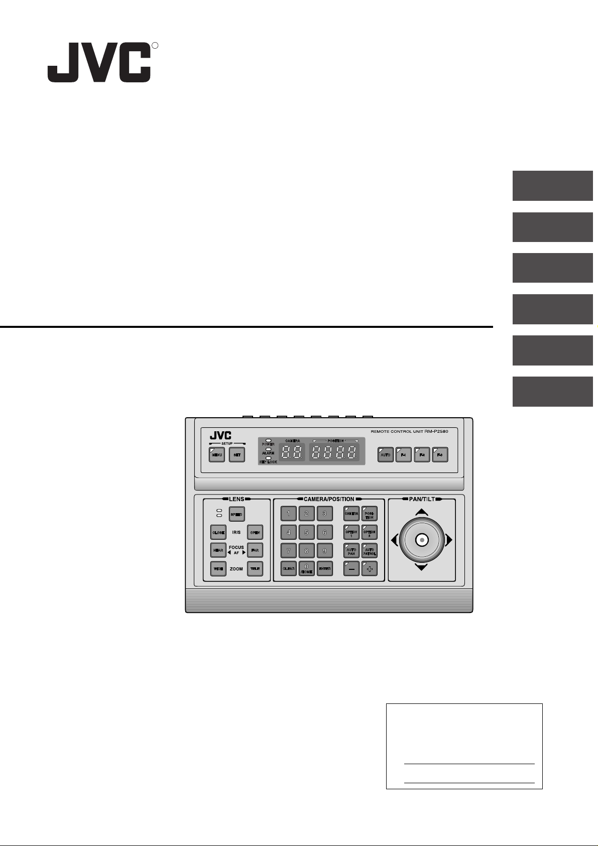
REMOTE CONTROL UNIT
RM-P2580
INSTRUCTIONS
CONNECTIONS
MENU SCREEN SETUPS
OTHER
For Customer Use:
Enter below the Model No. and Serial
No. which is located on the body. Retain
this information for future reference.
Model No. RM-P2580
Serial No.
SC96858-001
Page 2
SAFETY PRECAUTIONS
CAUTION
RISK OF ELECTRIC SHOCK
DO NOT OPEN
CAUTION : TO REDUCE THE RISK OF ELECTRIC SHOCK,
REFER SERVICING TO QUALIFIED SERVICE PERSONNEL.
DO NOT REMOVE COVER (OR BACK).
NO USER SERVICEABLE PARTS INSIDE.
The lightning flash with arrowhead symbol,
within an equilateral triangle is intended to alert
the user to the presence of uninsulated “dangerous voltage” within the product's enclosure
that may be of sufficient magnitude to constitute a risk of electric shock to persons.
The exclamation point within an equilateral triangle is intended to alert the user to the presence of important operating and maintenance
(servicing) instructions in the literature accompanying the appliance.
WARNING: T O REDUCE THE RISK OF FIRE OR
ELECTRIC SHOCK, DO NOT EXPOSE THIS
APPLIANCE TO RAIN OR MOISTURE.
Information for USA
This device complies with Part 15 of the FCC Rules.
Changes or modifications not approved by JVC could void
the user's authority to operate the equipment.
INFORMATION (FOR CANADA)
RENSEIGNEMENT (POUR CANADA)
This Class B digital apparatus meets all requirements of the
canadian Interference-Causing Equipment Regulations.
Cet appareil numérique de la classe B respecte toutes les
exigences du Réglement sur le matériel brouilleur du Canada.
Changes or modifications not approved by JVC could void
the user's authority to operate the equipment.
This unit is designed for professional use only.
Due to design modifications, data given in this instruction
book are subject to possible change without prior notice.
AVERTISSEMENT :
POUR EVITER LES RISQUES D’INCENDIE OU
D’ELECTROCUTION, NE PAS EXPOSER
L’APPAREIL A L’HUMIDITE OU A LA PLUIE.
2
Page 3

1. INTRODUCTION
Thank you for purchasing the JVC RM-P2580.
These instructions are for the RM-P2580U.
CONTENTS
1. INTRODUCTION
● CONTENTS.......................................................................................................................................... 3
● FEATURES........................................................................................................................................... 4
● ACCESSORIES ................................................................................................................................... 4
● PRECAUTIONS FOR PROPER OPERATION ..................................................................................... 4
● CONTROLS, CONNECTORS AND INDICATORS............................................................................... 5
2. BASIC OPERATIONS
● CAMERA SELECTION....................................................................................................................... 10
● POSITION SELECTION..................................................................................................................... 11
● MANUAL OPERATION ....................................................................................................................... 12
● AUTO SEQUENCE OPERATION ....................................................................................................... 13
● AUTO PAN OPERATION .................................................................................................................... 14
● AUTO PATROL OPERATION.............................................................................................................. 15
● KEY LOCK (PREVENTION OF OPERATION MISTAKE)................................................................... 16
3. APPLIED OPERATIONS
● ALARM OPERATION ......................................................................................................................... 17
● DATA OUTPUT ................................................................................................................................... 18
● CAMERA SWITCHING OPERATION................................................................................................. 18
4. CONNECTIONS
● BASIC SYSTEM (A MODE) ............................................................................................................... 19
● APPLIED SYSTEM (B MODE)........................................................................................................... 21
● REAR PANEL CONNECTORS .......................................................................................................... 23
5. MENU SCREEN SETUPS
● FLOW OF MENUS ............................................................................................................................. 25
● MENU OPERATION ........................................................................................................................... 26
● SETUP SCREEN (MAIN MENU)
POSITION SETUP SCREEN .......................................................................................................... 27
CAMERA SCREEN......................................................................................................................... 28
CONTROL UNIT SCREEN .............................................................................................................28
OPTION SCREEN..................................................................................................................... 29
DATA I/O SCREEN .................................................................................................................... 30
ALARM SCREEN ...................................................................................................................... 32
AUTO SEQUENCE SCREEN.................................................................................................... 32
6. OTHER
● TR OUBLESHOOTING........................................................................................................................ 33
● SPECIFICATIONS .............................................................................................................................. 34
3
Page 4
1. INTRODUCTION
FEATURES
䢇 Presetting of up to 64 positions (including the home positions) each, for up to 8 combination cameras (TK-C675B).
䢇 Built-in PAN, TILT and ZOOM control for up to 8 cameras.
䢇 RS-485 connection system enables cascaded connection of cameras.
䢇 Built-in sequential switcher.
䢇 Alarm input terminals.
䢇 Data I/O terminals for interlocked operation with external peripherals.
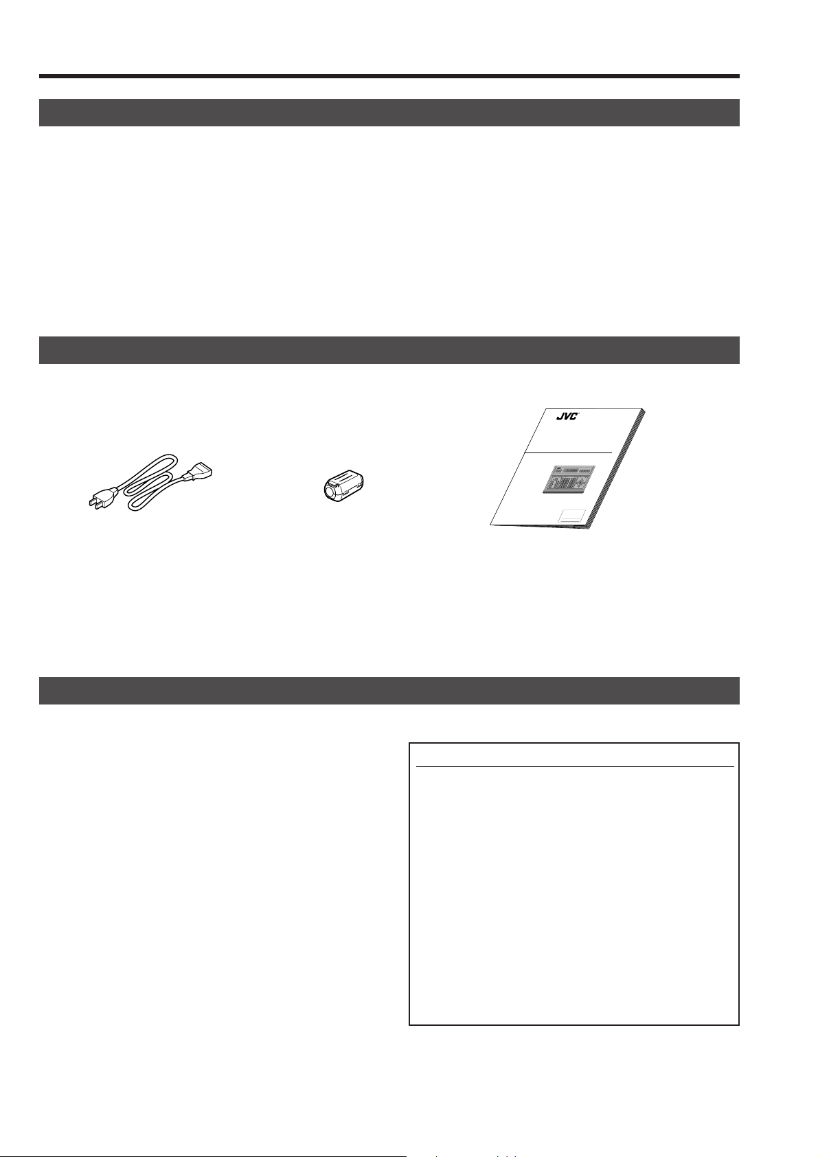
ACCESSORIES
R
Power cord (2 m) Ferrite Core Instructions (this manual)
PRECAUTIONS FOR PROPER OPERATION
䢇 Do not install the unit in a place subject to direct sunlight,
excessive moisture, dust, or vibrations where ventilation is
poor.
䢇 Be careful of strong radio waves and magnetism:
If the unit is near a source of strong magnetism, such as a
radio or TV transmission antenna, power transformer or
motor, the video signal may be subject to interference.
䢇 Always use the power cord provided with or specified for
this unit.
䢇 CLEAN EXTERIOR
● Wipe gently with a soft cloth.
● Put cloth in diluted mild soap and wring it well to wipe off
heavy dirt. Then wipe again with a dry cloth.
REMOTE CONTROL UNIT
RM-P2580
INSTRUCTIONS
REMOTE CONTROL UNIT
RM-P2000
CAMERACAMERA POSITIONPOSITION
SETUP
ALARMALARM
MENUMENU SETSET
AUTOAUTO F-1F-1 F-2F-2 F-3F-3
KEY LOCKKEY LOCK
PAN/TILTLENS
CAMERA/POSITION
CAMERACAMERA
POSI-POSI-
SPEEDSPEED
1
2
3
TIONTION
HOMEHOME FUNC-FUNC-
IRIS
OPENOPEN
CLOSECLOSE
4
5
6
TIONTION
FOCUS
PRESETPRESET
AUTOAUTO
FARFAR
NEARNEAR
7
8
9
AF
PANPAN
SEQSEQ
0
TELETELE CLEARCLEAR
ENTERENTER
WIDEWIDE
ZOOM
/ALL/ALL
For Customer Use:
Enter below the Model No. and Serial
No. which is located on the body. Retain
this information for future reference.
Model No. RM-P2580
Serial No.
Precautions for the PRESET SEQUENCE and AUTO PAN Operations
The life-span of the PRESET SEQUENCE and A UTO PAN
functions is dependent on which camera model is used in
combination with this unit.
When using a TK-C675B camera, the guaranteed z oom lens
operation count is 200,000 times. If the zoom lens operation is used often, the life-span of the PRESET SEQUENCE
and AUT O PAN functions may be much less than expected.
(Example) Assuming that a ZOOM operation is performed
every minute and the camera is used 24 hours
a day:
200,000 x 2 (times) ÷ 60 (minutes) ÷ 24 (hours) = 277 (days)
Total operations count Daily operating hours
For other camera models, please refer to the Handling &
Installation Instructions manuals of the camera in use.
4
Page 5
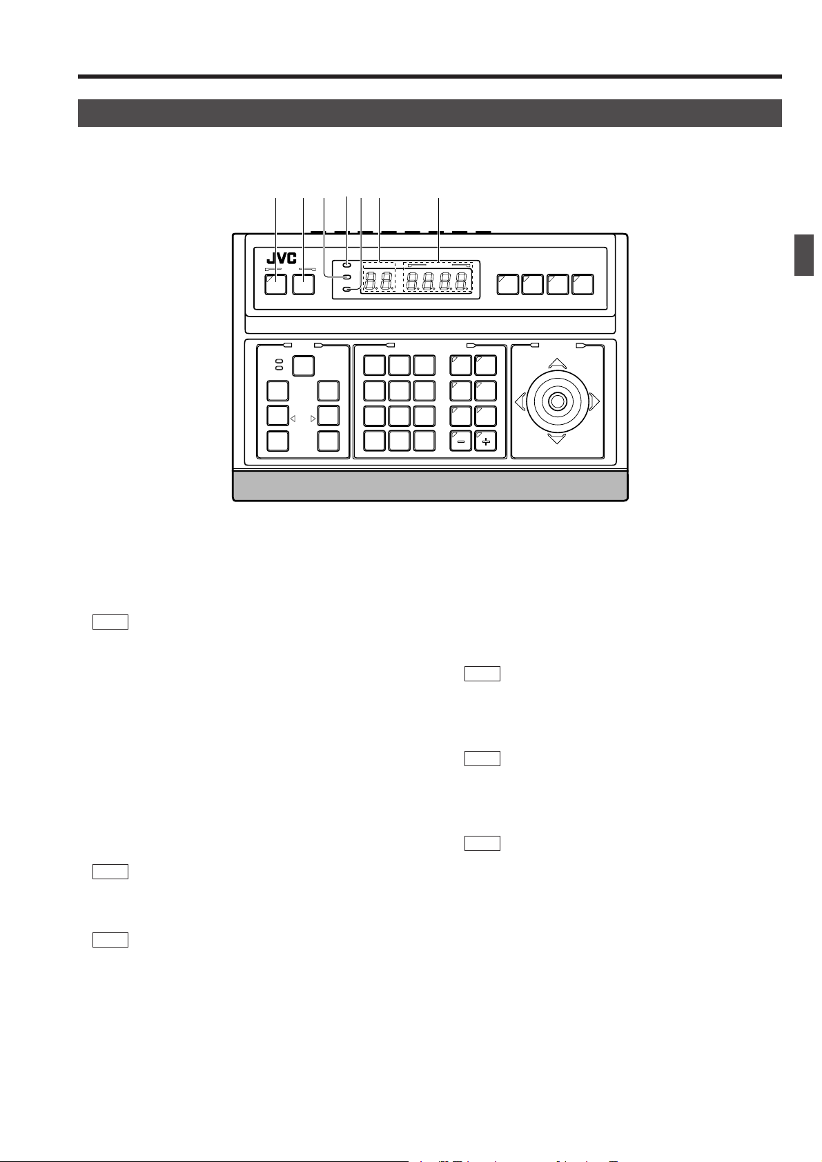
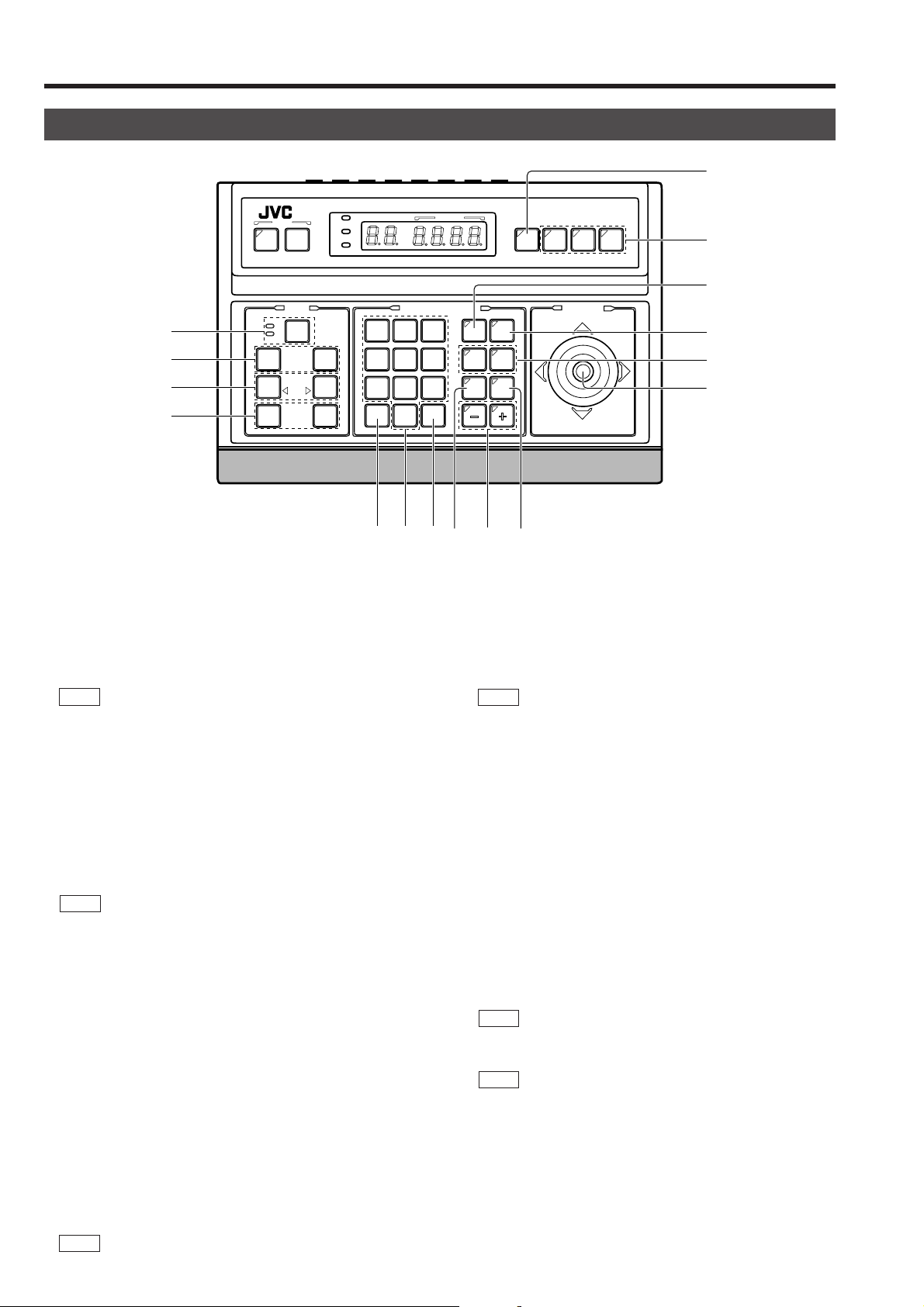
CONTROLS, CONNECTORS AND INDICATORS
[Control Panel]
1 2 4356 7
1. INTRODUCTION
POWER
ALARM
KEY LOCK
CAMERACAMERA POSITIONPOSITION
CAMERA/POSITIONCAMERA/POSITION
1
2
4
5
7
8
0
/HOME/HOME
[MENU] button (with an indicator)
1
SETUPSETUP
MENUMENU SETSET
SPEEDSPEED
CLOSECLOSE
FOCUSFOCUS
NEARNEAR
WIDEWIDE
ZOOMZOOM
IRISIRIS
AFAF
OPENOPEN
FARFAR
TELETELE CLEARCLEAR
When this button is pressed, the MONITOR OUTPUT 1
on the rear panel outputs a menu screen and the indi-
‚
cator with this button lights up.
REF. : “MENU SCREEN SETUP” on page 25.
[SET] button
2
● While a normal screen is displayed (i.e. when a menu
screen is not displayed), pressing and holding this button
for more than 3 seconds generates a short beep, lights up
the KEY LOCK indicator
and then puts the unit to the
5
KEY LOCK status.
In the KEY LOCK status, all buttons as well as the PAN/
TILT control lever
on the control panel are inactive.
#
To release the KEY LOCK status, press and hold the SET
button again for more than 3 seconds.
● While a menu screen is displayed, this button is used to
display a menu in a lower hierarch y le vel or to enter a setting.
REF. : “MENU SCREEN SETUP” on page 25.
ENTERENTER
REMOTE CONTROL UNIT REMOTE CONTROL UNIT
AUTOAUTO F-1F-1 F-2F-2 F-3F-3
CAMERACAMERA
3
6
9
POSI-POSI-
TIONTION
OPTIONOPTION
OPTIONOPTION
1
2
AUTOAUTO
AUTOAUTO
PANPAN
PATROLPATROL
[POWER] indicator
4
RM-P2580RM-P2580
PAN/TILTPAN/TILTLENSLENS
This indicator lights up when the POWER switch fi on the
rear panel is set to ON.
[KEY LOCK] indicator
5
This indicator lights up when the unit is in the KEY LOCK
status.
REF . : “
[CAMERA] display
6
[SET] button” f or the KEY LOCK status setting.
2
Shows the camera number of the camera signals output
from the MONITOR OUTPUT 1 connector
‚
.
REF. : “CAMERA SELECTION” on page 10.
[POSITION] display
7
Shows the position number of the camera signals output
from the MONITOR OUTPUT 1 connector
‚
.
REF. : “POSITION SELECTION” on page 11.
[ALARM] indicator
3
This indicator blinks when an alarm signal is input.
REF. : “ALARM OPERATION” on page 17.
5
Page 6
1. INTRODUCTION
CONTROLS, CONNECTORS AND INDICATORS (Continued)
8
[AUTO] button
8
‹
¤
⁄
)
SETUPSETUP
MENUMENU SETSET
SPEEDSPEED
CLOSECLOSE
FOCUSFOCUS
NEARNEAR
WIDEWIDE
ZOOMZOOM
IRISIRIS
AFAF
POPOWERWER
ALARMALARM
KEY LOCKKEY LOCK
OPENOPEN
FARFAR
TELETELE CLEARCLEAR
When this button is pressed, the unit enters the AUT O SEQUENCE mode, in which the indicator lights up and the
MONITOR OUTPUT 1 connector
on the rear panel out-
‚
put the camera video signals according to automatic switching.
REF. : “AUTO SEQUENCE OPERATION” on page 13.
CAMERACAMERA POSITIONPOSITION
CAMERA/POSITION
1
2
3
4
5
6
7
8
9
0
ENTERENTER
/HOME/HOME
*&(
REMOTE CONTROL UNIT REMOTE CONTROL UNIT
AUTOAUTO F-1F-1 F-2F-2 F-3F-3
RM-P2580RM-P2580
9
0
PAN/TILTPAN/TILTLENSLENS
CAMERACAMERA
POSI-POSI-
OPTIONOPTION
AUTOAUTO
PANPAN
TIONTION
OPTIONOPTION
1
2
AUTOAUTO
PATROLPATROL
!
@
#
$^ %
[POSITION] button
!
Press when selecting one of the position numbers preset
for the camera.
To select a position, use the following buttons:
POSITION button
TER button
&
REF. : “POSITION SELECTION” on page 11.
→ Numeric key buttons * → EN-
!
.
[F1, F2, F3] Function buttons
9
These buttons are valid only when SW-D7000/SW-D8000
frame switchers are being used.
When this unit is operated in the B mode, these buttons
can control certain functions of the specific frame switcher
model connected to this unit. The RS-232C control is involved in this control operation.
For details, please consult your dealer or JVC-authorized
service agent.
REF. : “APPLIED SYSTEM (B MODE)” on page 22.
F1: Single-screen select switch
Press this button to output a single-screen video from
the frame switcher.
The camera number can be selected using the numeric
keypad, etc.
F2: Split-screen select switch
Press this button to output a split-screen video from
the frame switcher.
F3: LIVE/PLAY switch
Press this button to switch between the pla yback video
of a time-lapse VCR and the camera video.
[CAMERA] button
0
Press when selecting a camera.
To select a camera, use the following buttons:
CAMERA button
ENTER button
→ Numeric key buttons * →
0
.
&
REF. : “CAMERA SELECTION” on page 10.
[OPTION 1, 2]
@
These buttons are not used for the present. Do not touch
them.
[PAN/TILT] control lever
#
Operate the lever to pan (swing horizontally) or tilt (swing
vertically) the rotary turret of a camera.
8(Up) : Tilt the lever in this direction to tilt the rotary
turret upward.
9(Down) :Tilt the lever in this direction to tilt the rotary
turret downward.
;(Right) : Tilt the lever in this direction to pan the rotary
turret toward the right.
:(Left) :Tilt the lever in this direction to pan the rotary
turret toward the left.
REF. : “MANUAL OPERATION” on page 12.
While a menu screen is displayed, this lever is used to
select or to set an item.
REF. : “MENU OPERATION METHOD” on page 26.
6
Page 7
CONTROLS, CONNECTORS AND INDICATORS (Continued)
1. INTRODUCTION
[AUTO PATROL] button
$
Press this button to switch the camera positions automatically in a preset order and at preset time intervals.
POSITION
The POSITION display becomes as shown on the left
during AUTO PATROL.
The AUTO PATROL function can be set on a per-camera
basis.
REF. : “AUTO PATROL OPERATION” on page 15.
[–, +] Negative and positive buttons
%
Press button to decrease or increase the camera or position number.
[AUTO PAN] button
^
Press this button to rotate or swing a camera between preset positions at a preset time interval.
POSITION
The POSITION display becomes as shown on the left
during AUTO PAN.
[FOCUS NEAR, FAR] FOCUS control buttons
⁄
● Press and hold to control the FOCUS operation of the camera lens.
NEAR: Brings a near object in focus.
FAR : Brings a distant object in focus.
● AF (AUTO FOCUS)
When the NEAR and FAR buttons are simultaneously
pressed and held for about 1 second, a short beep is generated and the object is automatically brought into focus.
NOTE
If the camera being selected does not incorporate the
AUTO FOCUS function, this function is not available
even when the short beep is generated. Be sure to use
this function while observing the monitor screen.
[IRIS CLOSE, OPEN] Iris control button.
¤
Press and hold to control the lens iris.
CLOSE : Closes the lens iris.
OPEN : Opens the lens iris.
[SPEED] Speed button and indicators
‹
Press to set the speed of the ZOOM and FOCUS control
operations.
REF. : “AUTO PAN OPERATION” on page 14.
[ENTER] button
&
Press to enter a figure input using the numeric key buttons
.
*
[1 to 0/HOME] Numeric key buttons
*
Use these buttons to choose a camera or position number .
[CLEAR] button
(
Press to clear an input figure before it is entered by pressing the ENTER button.
[ZOOM WIDE, TELE] ZOOM control buttons
)
Press and hold to control the ZOOM operation of the camera lens.
WIDE: Zooms out and widens the image.
TELE: Zooms in and narrows the image.
: Low speed : Medium speed : High speed
Each press of the button changes the operation speed.
NOTE
When the power is turned on, the operation speed is
medium.
7
Page 8
1. INTRODUCTION
CONTROLS, CONNECTORS AND INDICATORS (Continued)
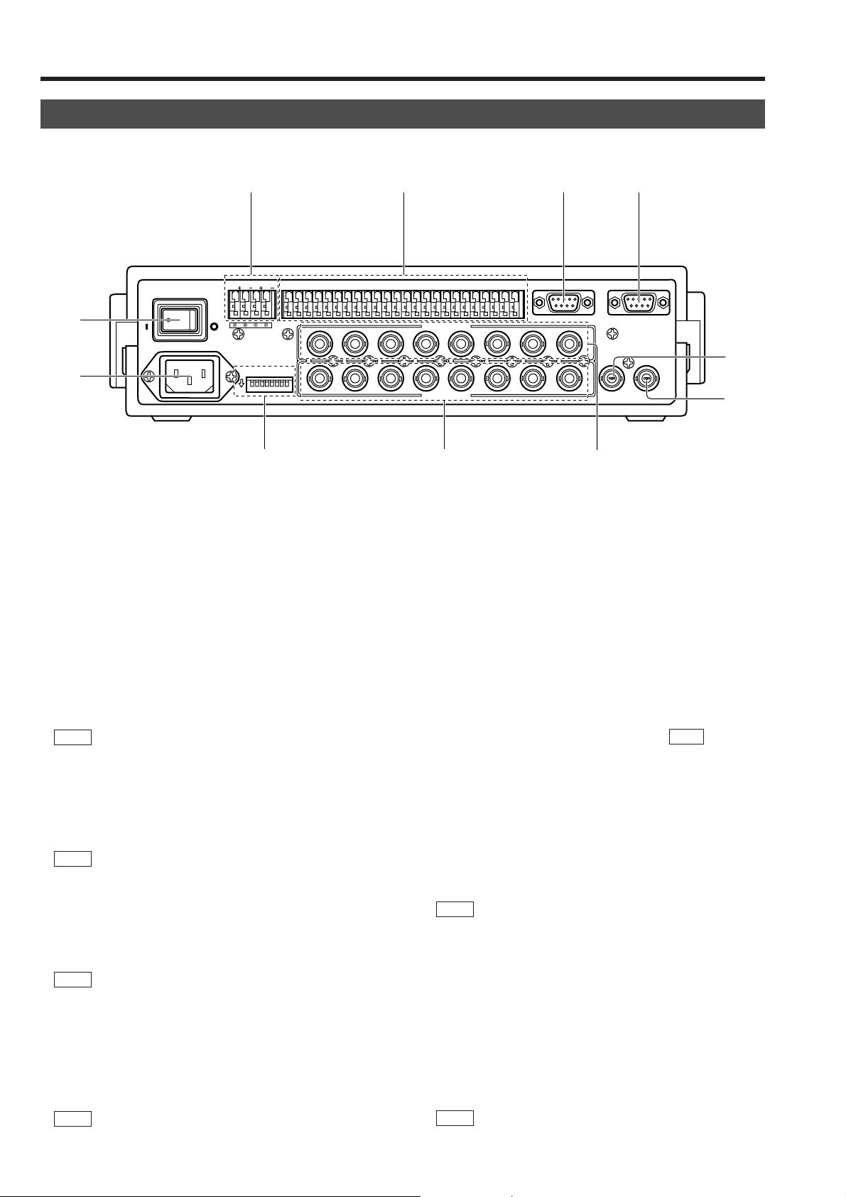
[Rear Panel]
fl ‡ °
TO CAMERATO CAMERA DATA I / ODATA I / O
-
fi
›
ON
POWER
`
AC INPUT
RXRX+RXRX-TXTX+TXTX
OFF
ONON
COMCOM
431 2 875 6
1 2 3 4 5 6 7 8
1
1
¢
[AC`INPUT] AC power input connector
›
Connect to a conventional 120 V AC power supply using
the provided power cord.
[POWER] switch
fi
Turns the power of the unit ON and OFF. When this s witch
is set to ON, the POWER indicator
lights up.
[TO CAMERA] Camera control signal connector s
fl
Connection terminals for use in controlling the cameras.
The control communications use the multi-drop, full-duple x
communication system (RS-485).
REF. :“REAR P ANEL CONNECTORS (T O CAMERA)” on
page 23.
[DATA I/O] Data signal input/output terminals
‡
Connection terminals for use by the alarm input/output and
select output signals.
Connect the CAMERA SW terminal to a time-lapse VCR.
REF. : “REAR PANEL CONNECTORS (DATA I/O)” on
page 24.
[SERIAL-1] External extension connector 1
°
(D-sub 9-pin male connector)
Use this connector when connecting an external component such as an alarm unit.
REF. :“REAR P ANEL CONNECTORS (SERIAL-1, -2)” on
page 23.
Contact your JVC sales agent for details.
[SERIAL-2] External extension connector 2
·
(D-sub 9-pin male connector)
Use this connector when controlling a frame switcher (SWD7000/SW-D8000).
REF. :“REAR P ANEL CONNECTORS (SERIAL-1, -2)” on
page 23.
on the front panel
4
UNITUNIT
COMCOM
9/19/1 10/210/2 11/311/3 12/412/4 13/513/5 14/614/6 15/715/7 16/816/8
2 3 4 5 6 7
2 3 4 5 6 7
VIDEO INPUT
VIDEO OUTPUTVIDEO OUTPUT
CAMERACAMERA
COMCOM COMCOM COMCOM
SWSW
ALARM
AUTOAUTO
£
[MONITOR OUTPUT 1] Video signal output con-
‚
nector 1
Outputs the video signal selected with this unit.
Connect to the video monitor, etc.
This connector also outputs the video signal, which carries the on screen menu.
[MONITOR OUTPUT 2] Video signal output con-
¡
nector 2
Connect to a time-lapse VCR, etc.
The camera video signal output from this connector is
switched according to the switching signal input at the
CAMERA SW IN terminal
When this unit is operated in the B mode ( REF . : Page 21):
This connector outputs the same signal as the MONITOR
OUTPUT 1 connector
[VIDEO INPUT] Video signal input connectors
™
These connectors input the video signals from the cameras.
When this unit is operated in the B mode, apply the output
signal from a frame switcher to the VIDEO INPUT 1 connector.
REF . :“BASIC SYSTEM” on page 19, “APPLIED SYSTEM”
on page 21.
[VIDEO OUTPUT] Video signal output connectors
£
Each of these connectors outputs the video signal corresponding to the VIDEO INPUT connector
Connect these connectors to a video device such as a
monitor.
DIP switch
¢
Used to switch the system mode or the standard applied
to the SERIAL-1 and -2 connectors.
REF. :“REAR P ANEL CONNECTORS (DIP SWITCH)” on
page 23.
·
SERIAL-2SERIAL-2SERIAL-1SERIAL-1
8
8
MONITOR
OUTPUT
1
MONITOR
OUTPUT
2
‚
¡
™
.
‡
.
‚
above it.
™
8
Page 9
2. BASIC OPERATIONS
1
/HOME
0
ENTER
POSI-
TION
Camera 1
scene
Camera 8
scene
Camera 2
scene
AUTO
Manual Operation
Camera Selection ( REF. :Page 10)
Switching to the selected camera video.
CAMERA
1
8
Pan/Tilt Operation ( REF. : Page 12)
PAN/TILT
(TILT) Tilts the camera up and do wn,
(P AN) P ans the camera in the left and
right directions.
Automatic Operation
ENTER
Position Selection ( REF. : Page 11)
Switching the camera to the selected video position.
Lens Operation ( REF. : Page 12)
CLOSECLOSE
NEARNEAR
WIDEWIDE
IRIS
FOCUS
AF
ZOOM
OPENOPEN
FARFAR
TELETELE
Operation of the Camera IRIS
(Brightness), FOCUS (focusing) and ZOOM (screen size).
Auto Sequence ( REF. : Page 13)
The scene captured by cameras 1 to 8 is automatically switched in a preset time interval.
Auto Panning ( REF. : Page 14)
The camera moves automatically and slowly between 2 points
in a horizontal direction.
AUTO
PAN
Slowly
Start
position
scene
Stop
position
scene
Auto Patrol ( REF. : Page 15)
Moves the camera through many positions in a high-speed
manner.
AUTO
PATROL
Position
High-speed High-speed
High-speed
Position
1
2
Position
4
High-speed
Position
3
9
Page 10
2. BASIC OPERATIONS
K
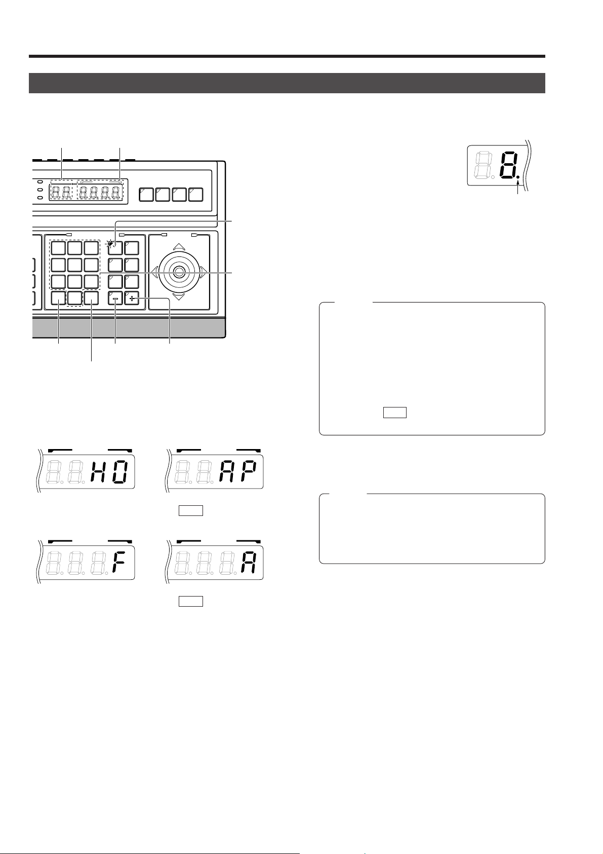
CAMERA SELECTION
Selecting a Desired Camera
CAMERA display POSITION display
CAMERACAMERA
OPTIONOPTION
1
AUTOAUTO
PANPAN
REMOTE CONTROL UNIT REMOTE CONTROL UNIT
AUTOAUTO F-1F-1 F-2F-2 F-3F-3
POSI-POSI-
TIONTION
OPTIONOPTION
2
AUTOAUTO
PATROLPATROL
+ buttonCLEAR button
PAN/TILTPAN/TILT
CAMERACAMERA POSITIONPOSITION
POPOWERWER
ALARMALARM
EY LOCKKEY LOCK
1
4
7
CLEARCLEAR
CAMERA/POSITIONCAMERA/POSITION
2
3
5
6
8
9
0
ENTERENTER
/HOME/HOME
- button
ENTER button
Camera operation details
RM-P2580RM-P2580
CAMERA
button
Numeric key
buttons
1.
Press the CAMERA button so that the indicator lights up.
2.
Input the camera number using the numeric keys (0 to 9).
The input figure is shown in the
CAMERA
CAMERA display together with
a period after it. (Example: When
“8” is input)
To clear the input figure, press
the CLEAR button.
3.
Press the ENTER button to enter the input camera number .
The video of the selected camera will be output from the
MONITOR OUTPUT connectors on the rear panel.
At this time, the period in the CAMERA display disappears
and the POSITION display shows the camera operation
details (position, fixed camera, AUTO PATROL, AUTO
PAN, etc.).
NOTES
● “Camera video” is one of the video signals input to
the VIDEO INPUT connector of this unit or to the frame
switcher .
● In the case of the B mode in which the output video is
controlled by the frame switcher , in order to allow camera selection from this unit, connect the SERIAL-2
connector on the rear panel of the unit with the RS232C connector of the frame switcher. (SW-D7000/
SW-D8000)( REF. : “APPLIED SYSTEM (B MODE)”
on page 22.)
Period
POSITION POSITION
4.
To view the video of the next camera number, press the +
button. To vie w the video of the pre vious camera number,
press the – button.
Position display
(Example with the
home position)
AUTO PATROL
( REF. : Page 15)
NOTES
● When no camera is connected to a camera number,
the camera number is skipped.
● Be sure to set each camera ID to the same number
POSITION POSITION
as the corresponding VIDEO INPUT connector. Erroneous settings may cause operational difficulties.
Fixed camera display
AUTO PAN
( REF. : Page 14)
10
Page 11

2. BASIC OPERATIONS
K
POSITION
Period
K
POSITION SELECTION
Selecting a Desired Preset Position ( REF. : Page 27 for the position presetting.)
1.
Press the POSITION button so that the indicator lights up.
2.
CAMERA display POSITION display
CAMERACAMERA
OPTION
1
AUTOAUTO
PANPAN
REMOTE CONTROL UNIT REMOTE CONTROL UNIT
AUTO F-1 F-2 F-3
POSITION
OPTION
2
AUTOAUTO
PATROLPATROL
+ buttonCLEAR button
PAN/TILT
CAMERA POSITION
POPOWERWER
ALARMALARM
EY LOCKKEY LOCK
1
4
7
CLEAR
CAMERA/POSITIONCAMERA/POSITION
2
3
5
6
8
9
0
ENTER
/HOME
- button
ENTER button
RM-P2580RM-P2580
POSITION
button
Numeric key
buttons
Input the position number using the numeric keys (0 to 9).
The input figure is shown in the POSITION display together with a period after it.
(Example: When “48” is input)
To clear the input figure, press the CLEAR button.
3.
Press the ENTER button to enter the input position number.
The video of the selected position will be output from the
MONITOR OUTPUT connectors on the rear panel.
At this time, the period in the POSITION display disappears.
NOTE
When a position number that has not been preset is
selected, the POSITION display shows the selected
position number but the video is not switched to that
position.
4.
To view the video of the next recorded position number,
press the + button. To view the video of the previous recorded position number, press the – b utton.
NOTE
When TK-C675B cameras are used, mak e sure that the lower 4 digits inscribed on the serial number on their rear panels are as
shown below. Otherwise the cameras cannot be moved to the desired positions.
TK-C675BU: #0060 or after
When the serial number of a camera is other than the above, please consult your nearest JVC-authorized service agent.
Setting All Cameras to the Home Positions ( REF. : Page 27 for the home position presetting.)
1.
CAMERA display POSITION display
CAMERACAMERA
OPTIONOPTION
1
AUTOAUTO
PANPAN
REMOTE CONTROL UNIT REMOTE CONTROL UNIT
AUTOAUTO F-1F-1 F-2F-2 F-3F-3
POSI-POSI-
TIONTION
OPTIONOPTION
2
AUTOAUTO
PATROLPATROL
CAMERACAMERA POSITIONPOSITION
POPOWERWER
ALARMALARM
EY LOCKKEY LOCK
CAMERA/POSITION
3
2
CLEARCLEAR
1
6
5
4
9
8
7
0
ENTERENTER
/HOME/HOME
RM-P2580
PAN/TILTPAN/TILT
CAMERA
button
Press the CAMERA button so that the indicator lights up.
2.
Press the HOME button. The CAMERA display shows “A”
and POSITION display shows “
H0”.
CAMERA POSITION
3.
Press the ENTER button to move all the cameras into
their home positions.
When the cameras have moved to the home positions,
the CAMERA display shows the camera number that w as
selected before the HOME button was pressed.
HOME
button
11
Page 12

2. BASIC OPERATIONS
MANUAL OPERATION
The manual operation allows you to PAN or TILT the selected camera and to control its lens.
SETUPSETUP
MENUMENU SETSET
CLOSECLOSE
FOCUSFOCUS
NEARNEAR
WIDEWIDE
SPEEDSPEED
IRISIRIS
AFAF
ZOOMZOOM
POWERWER
ALARM
KEY LOCK
OPENOPEN
FARFAR
TELETELE CLEARCLEAR
CAMERACAMERA POSITIONPOSITION
CAMERA/POSITIONCAMERA/POSITION
1
2
3
4
5
6
7
8
9
0
ENTERENTER
/HOME/HOME
CAMERACAMERA
OPTIONOPTION
AUTOAUTO
PANPAN
1
REMOTE CONTROL UNIT REMOTE CONTROL UNIT
AUTOAUTO F-1F-1 F-2F-2 F-3F-3
POSI-POSI-
TIONTION
OPTIONOPTION
2
AUTOAUTO
PATROLPATROL
RM-P2580RM-P2580
PAN/TILTPAN/TILTLENSLENS
Lens operation PAN/TILT control lever
Operating the PAN/TILT Control Lever
Up
Upper left Upper right
PAN/TILT
Left Right
Low speed
Variable in
max. 8 steps
High speed
NOTES
● Manual operation is not available in the AUTO
SEQUENCE or AUTO PATROL modes.
● Only the lever tilting operation is available in the AUTO
PAN mode.
● The rotary turret of the camera rotates according to the direction in which the PAN/TILT lever is tilted.
● The speed of rotation depends on the angle of tilt of the
control lever. The greater the tilt, the faster the speed.
The speed at each step value can be changed according
to the tilt angle.
Lower left
Lower right
Down
Operation method Speed
Operating the Lens
SPEED buttons
IRIS control buttons
FOCUS control buttons
ZOOM control buttons
CLOSECLOSE
NEARNEAR
WIDEWIDE
LENS
SPEEDSPEED
IRIS
FOCUS
AF
ZOOM
OPENOPEN
FARFAR
TELETELE
REF. : “P/T SPEED” on page 29 for how to change the le ver
sensitivity .
● IRIS
T o adjust the video image brightness, press and hold one of
the IRIS control buttons until the desired brightness is obtained.
CLOSE : Closes the lens iris.
OPEN : Opens the lens iris.
The iris operation continues as long as the button is being
pressed.
● FOCUS
To adjust the focus, press and hold one of the FOCUS control buttons until the desired focus is obtained.
NEAR : Brings a near object into focus.
FAR : Brings a far object into focus.
The focus operation continues for as long as the button is
being pressed.
● ZOOM
To adjust the video image size, press and hold one of the
ZOOM control buttons until the desired size is obtained.
WIDE: Zooms out and widens the image.
TELE: Zooms in and narrows the image.
The zoom operation continues for as long as the button is
being pressed.
12
The movement speeds of zoom and focus are variable with
SPEED button.
REF. : “SPEED button” on the page 7.
Page 13
2. BASIC OPERATIONS
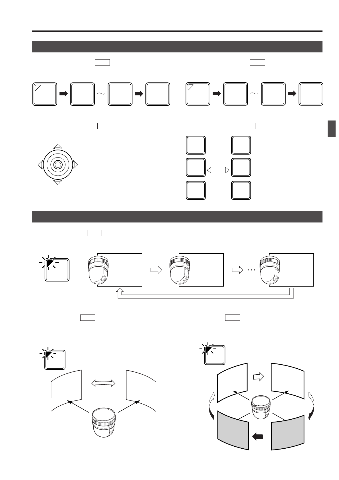
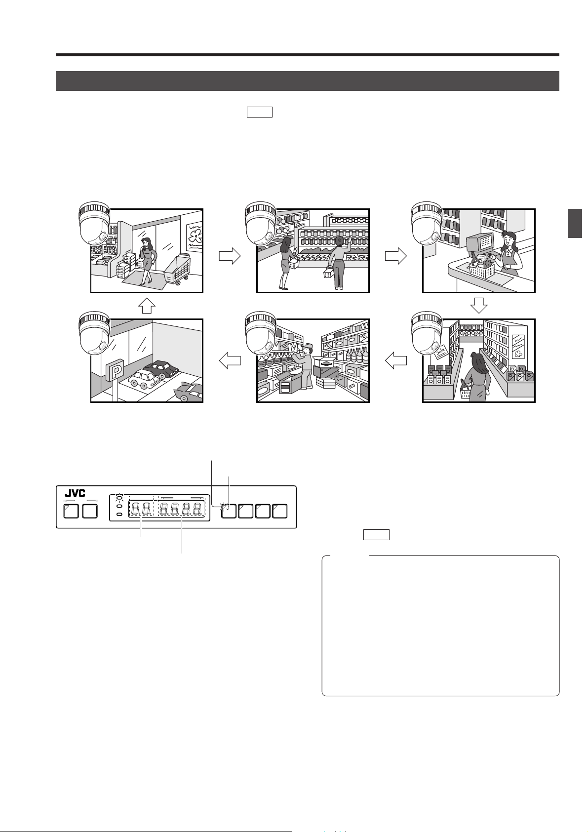
AUTO SEQUENCE OPERATION
Operation with the Basic System ( REF. : Page 32 for the switching interval setting.)
When the AUTO button is pressed, the AUTO indicator lights up and the MONITOR OUTPUT connectors output the camera
images, switching them in order of camera numbers at constant intervals.
(Example) When using cameras 1 to 6
Camera 1 Camera 2 Camera 3
Camera 6 Camera 5 Camera 4
Lights up.
AUTO button
REMOTE CONTROL UNIT REMOTE CONTROL UNIT
SETUPSETUP
MENUMENU SETSET AUTOAUTO F-1F-1 F-2F-2 F-3F-3
POPOWERWER
ALARMALARM
KEY LOCKKEY LOCK
CAMERACAMERA POSITIONPOSITION
RM-P2580RM-P2580
CAMERA display
POSITION display
1.
Press the AUT O b utton.
The LED indicator lights up and the AUTO SEQUENCE
operation starts.
The CAMERA display shows the camera number of the
video being output from the MONITOR OUTPUT 1 connector.
The POSITION display shows the camera operation details. ( REF. : Page 10)
NOTES
● During the AUTO SEQUENCE operation, the camera
selection, manual selection, AUTO PAN operation and
AUTO PATROL operation are not available.
● When the auto mode AUTO SEQUENCE operation is
switched from ON to OFF, the MONITOR OUTPUT connectors output the video at the moment of the ON-OFF
switching.
● In the case of Applied System (B Mode), the video from
the MONITOR OUTPUT is displayed in either auto sequence or in multi-split screen depending on the setting
of the connected frame switcher.
2.
T o stop the A UTO SEQUENCE operation, press the A UT O
button once again.
13
Page 14

2. BASIC OPERATIONS
AUTO PAN OPERATION
The AUTO PAN operation consists of low-speed horizontal movement of a camera between preset positions
at a constant time interval.
Automatic panning is set between 2 points.
This function can be set on individual cameras.
SETUPSETUP
MENUMENU SETSET
CLOSECLOSE
FOCUSFOCUS
NEARNEAR
WIDEWIDE
ZOOMZOOM
SPEEDSPEED
IRISIRIS
AFAF
POPOWERWER
ALARMALARM
KEY LOCKKEY LOCK
OPENOPEN
FARFAR
TELETELE CLEARCLEAR
POSITION displaySET button
CAMERACAMERA POSITIONPOSITION
CAMERA/POSITION
1
2
3
4
5
6
7
8
9
0
ENTERENTER
/HOME/HOME
AUTO PAN
button
CAMERACAMERA
OPTIONOPTION
1
AUTOAUTO
PANPAN
REMOTE CONTROL UNIT REMOTE CONTROL UNIT
AUTOAUTO F-1F-1 F-2F-2 F-3F-3
POSI-POSI-
TIONTION
OPTIONOPTION
2
AUTOAUTO
PATROLPATROL
RM-P2580RM-P2580
PAN/TILTPAN/TILTLENSLENS
PAN/TILT
control lever
1.
Press the AUTO PAN button. The LED indicator lights up
and the AUTO PAN operation starts.
The POSITION display shows “
A” at this time.
NOTE
During the AUTO PAN operation, the PAN/TILT control
lever can be operated only in the TILT direction (
2.
To stop the AUTO PAN operation, press the AUTO PAN
button again.
NOTES
● The AUTO PAN operation also stops when a preset
position is selected or the AUTO PATROL operation
is started.
REF. : “POSITION SELECTION” on Page 11 and
“AUTO PATROL OPERATION” on page 15.
● The AUTO PAN operation is set on the CAMERA
SCREEN ( REF. : P age 28). Open the camera menu
screen to perform the setting.
As the rest of the setting procedure is variable depending on the camera models, please refer to the
Instruction manual of the connected camera.
).
14
Page 15

2. BASIC OPERATIONS
AUTO PATROL OPERATION
The AUTO PATROL operation consists of high-speed camera movement between multiple pre-set positions,
in a sequence and at time intervals set by the user.
This function can be set on individual cameras.
SETUPSETUP
MENUMENU SETSET
CLOSECLOSE
FOCUSFOCUS
NEARNEAR
WIDEWIDE
ZOOMZOOM
SPEEDSPEED
IRISIRIS
AFAF
POPOWERWER
ALARMALARM
KEY LOCKKEY LOCK
OPENOPEN
FARFAR
TELETELE CLEARCLEAR
POSITION display
CAMERACAMERA POSITIONPOSITION
CAMERA/POSITION
ENTERENTER
CAMERACAMERA
3
OPTIONOPTION
6
1
AUTOAUTO
9
PANPAN
1
2
4
5
7
8
0
/HOME/HOME
AUTO PATROL button
REMOTE CONTROL UNIT
AUTOAUTO F-1F-1 F-2F-2 F-3F-3
POSI-POSI-
TIONTION
OPTIONOPTION
2
AUTOAUTO
PATROLPATROL
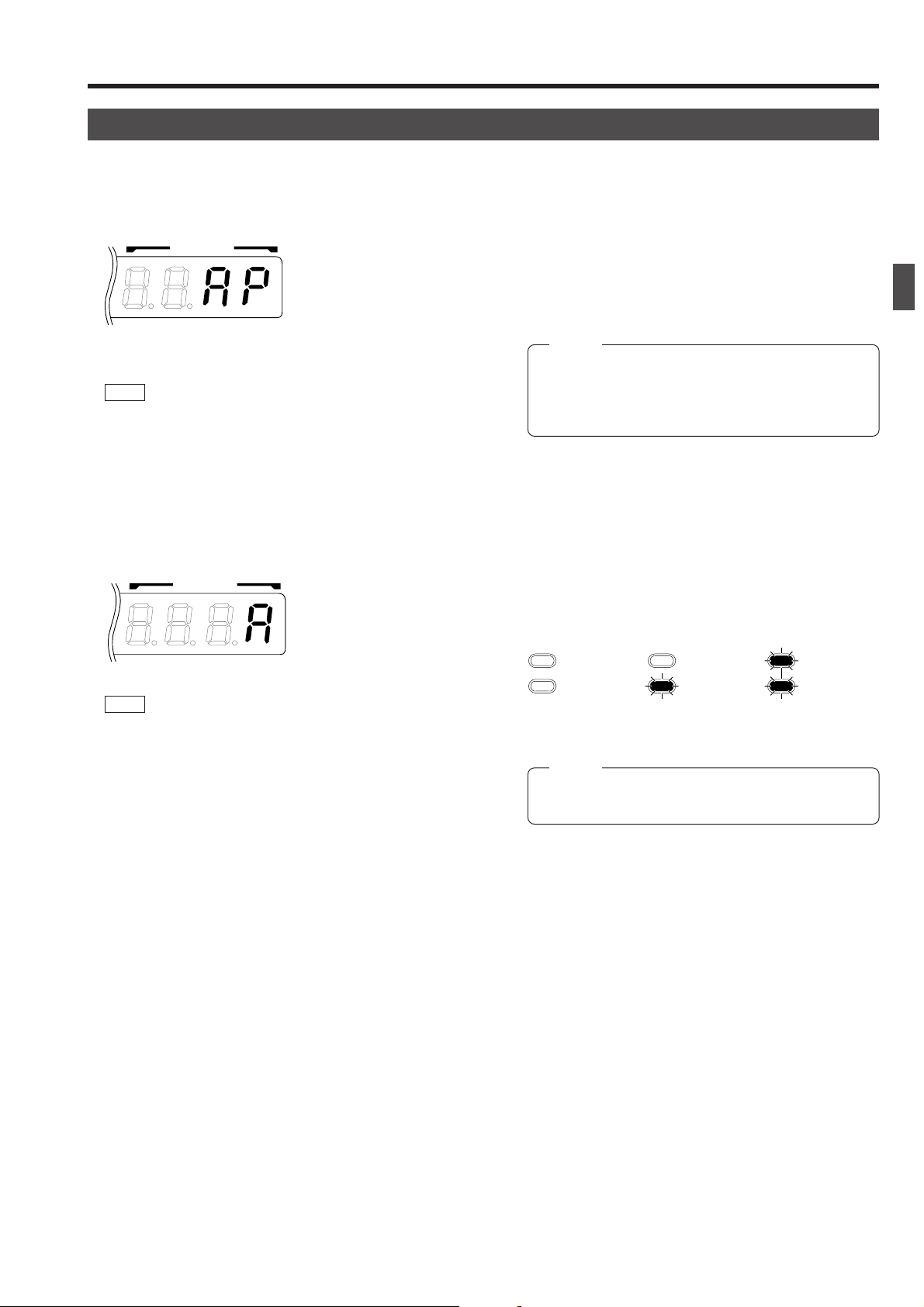
1.
Press the AUT O PA TROL button. The LED indicator lights
up and the AUTO PATROL operation starts.
RM-P2580
The POSITION display shows “
AP” at this time.
NOTE
During the AUTO PATROL operation, the manual
operation is not available.
PAN/TILTLENS
2.
To stop the AUTO PATROL operation, press the AUTO
PATROL button again.
NOTES
● The A UTO PA TROL operation also stops when a preset position is selected or the AUTO PAN operation
is started.
REF. : [POSITION SELECTION] on Page 11 and
[AUTO PAN OPERATION] on page 14.
● The AUTO PAN operation is set on the CAMERA
SCREEN ( REF. : P age 28). Open the camera menu
screen to perform the setting.
As the rest of the setting procedure is variable depending on the camera models, please refer to the
instruction manual of the connected cameras.
15
Page 16

2. BASIC OPERATIONS
KEY LOCK (PREVENTION OF OPERATION MISTAKE)
The KEY LOCK function helps prevent operational mistakes by inhibiting the functions of all the buttons and
the joystick on the control panel.
SET button
SETUPSETUP
MENUMENU SETSET
SPEEDSPEED
IRISIRIS
CLOSECLOSE
FOCUSFOCUS
NEARNEAR
AFAF
WIDEWIDE
ZOOMZOOM
KEY LOCK
indicator
CAMERACAMERA POSITIONPOSITION
POPOWERWER
ALARMALARM
KEY LOCKKEY LOCK
OPENOPEN
FARFAR
TELETELE CLEARCLEAR
CAMERA/POSITION
1
2
4
5
7
8
0
/HOME/HOME
ENTERENTER
1.
Press and hold the SET button for more than 3 seconds
to put the unit into KEY LOCK status. The KEY LOCK
indicator lights up, and all the buttons and the jo ystick on
REMOTE CONTROL UNIT REMOTE CONTROL UNIT
AUTOAUTO F-1F-1 F-2F-2 F-3F-3
RM-P2580RM-P2580
the control panel become inactive.
2.
To cancel KEY LOCK, press and hold the SET button for
3 seconds or more, again.
The KEY LOCK indicator goes off and the KEY LOCK
PAN/TILTPAN/TILTLENSLENS
CAMERACAMERA
OPTIONOPTION
AUTOAUTO
POSI-POSI-
TIONTION
OPTIONOPTION
1
2
AUTOAUTO
PANPAN
PATROLPATROL
3
6
9
status is cancelled.
NOTE
●Even if the power is turned OFF, the KEY LOCK status remains on.
16
Page 17

3. APPLIED OPERATIONS
ALARM OPERATION
Alarm input signals can be applied to the DATA I/O terminals on the rear panel. The unit functions in either the
ALARM PRIORITY mode or the MANUAL PRIORITY mode when an alarm signal is input. ( REF. : “CONTROL
UNIT SCREEN” on page 28 and “PRIORITY item of ALARM SCREEN” on page 32.)
SETUP
MENUMENU SET
CLOSE
NEARNEAR
WIDEWIDE
SPEED
IRISIRIS
FOCUSFOCUS
ZOOMZOOM
AFAF
POWER
ALARM
KEY LOCK
OPENOPEN
FAR
TELE CLEAR
CAMERACAMERA POSITIONPOSITION
CAMERA/POSITIONCAMERA/POSITION
1
2
3
4
5
6
7
8
9
0
ENTER
/HOME/HOME
CAMERACAMERA
OPTIONOPTION
AUTOAUTO
1
PANPAN
REMOTE CONTROL UNIT REMOTE CONTROL UNIT
POSI-POSI-
TION
OPTIONOPTION
2
AUTOAUTO
PATROLPATROL
RM-P2580RM-P2580
AUTOAUTO F-1 F-2 F-3F-3
PAN/TILTPAN/TILTLENSLENS
ON
TO CAMERATO CAMERA DATA I / ODATA I / O
RX+RX-TX+TX
POWER
OFF
`
AC INPUT
ON
DATA I/O terminals
-
COMCOM
1 2 3 4 5 6 7 8
COMCOM
9/19/1 10/210/2 11/311/3 12/412/413/513/514/614/6 15/715/7 16/816/8
1
2 3 4 5 6 7
431 2 875 6
2 3 4 5 6 7
1
VIDEO INPUTVIDEO INPUT
VIDEO OUTPUT
UNITUNIT
COMCOM COMCOM COMCOM
ALARMALARM
AUTOAUTO
CAMERACAMERA
SWSW
SERIAL-2SERIAL-2SERIAL-1SERIAL-1
8
MONITORMONITOR
MONITORMONITOR
OUTPUTOUTPUT
1
8
Alarm Operation Modes
When an alarm signal is received, this unit performs the following operations.
<Alarm priority mode>
● The video is switched to the camera position from which the alarm signal is received.
● An alarm signal will automatically override and cancel the operation of either AUTO PATROL or AUTO SEQUENCE. (AUTO
SEQUENCE: In A mode only.)
● The preset alarm title is displayed in the preset size.
● The ALARM indicator blinks and the buzzer sounds. ( REF. : “BUZZER TIME” on page 32 for the setting method.)
● The CAMERA display indicates the number ID of the camera which has given the alarm signal.
● The UNIT ALARM output is turned ON.
<Manual priority mode>
● When an alarm signal is received during manual operation (except during the AUTO PAN, AUTO PATROL and AUTO SEQUENCE operations), the alarm operation does not start.
● When an alarm signal is received from a camera other than the camera being controlled manually, the alarm operation starts
but, unlike in the alarm priority mode, the buzzer does not sound and the camera in question is not automatically selected.
OUTPUTOUTPUT
2
<Example when Alarm 1 and Alarm 2 are input during AUTO SEQUENCE in the A Mode>
Alarm input 1
Alarm input 1
Alarm input 2
Camera 1 alarm time
Camera 2 alarm time
UNIT ALARM
output duration
MONITOR OUTPUT 1
MONITOR OUTPUT 2
CAMERA3 CAMERA2
Set in item "TIME" in the AUTO SEQUENCE screen.
CAMERA2 CAMERA3
Time period of switching by CAMERA SW.
CAMERA4
CAMERA CAMERA
CAMERA CAMERA
• In B mode, the MONITOR OUTPUT 2 connector outputs the same video as the MONITOR OUTPUT 1 connector.
For B Mode connection. REF. : [Applied System (B Mode)] on page 21.
B Mode output signal REF. : [B Mode] on page 22.
• While the MENU screen is displayed, the alarm signal is not accepted.
Alarm input 2
ALARM TIME
ALARM TIME
CAMERA3
CAMERA4 CAMERA5 CAMERA6 CAMERA7
*Encircled number shows the alarm condition.
Time
17
Page 18

Page 19

Page 20

4. CONNECTIONS
A MODE
● The master monitor displays the video signal from the selected camera.
● Use the CAMERA SW input to switch the video signal and record it on the VCR.
● The preset operation, manual operation, AUTO PAN operation and AUTO PATROL operation are available for each camera.
● When fixed cameras are used, only the video signal can be switched.
● The alarm operation is available using the DATA I/O terminals.
● Alarms with up to 64 positions per camera can be handled via the SERIAL-1 connector.
In the A mode, in which the camera signals are input directly to the VIDEO INPUT connectors on the rear panel, the DATA I/O
terminals outputs as shown in the following table :
Terminal Name
AUTO
I/O 1 to 8
(I/O 9/ to 16/8)
Condition
—
When 8 SEL OUT is set
• I/O 1 to 8 correspond to
cameras 1 to 8.
Signals
The MAKE signal is output for between 500 ms and 1000 ms duration
in the following cases.
● Power OFF ➝ ON.
● AUTO SEQUENCE (AUTO button OFF → ON)
● When an AUT O SEQUENCE operation which has been interrupted
by an alarm input resumes.
The MAKE signal is output for between 500 ms and 1000 ms duration
from the terminal corresponding to the camera number in the following cases.
● When AUT O SEQUENCE is turned OFF, the MAKE signal is output
to the Camera No. terminal corresponding to the camera displayed
on the camera indication.
● With AUT O SEQUENCE set to OFF, each time when the camera is
selected, the MAKE signal is output to the Camera No. terminal
corresponding to the camera selected.
● If an Alarm is input when AUTO SEQUENCE is activ ated, the MAKE
signal is output to the Camera No. terminal corresponding to the
camera to which the Alarm signal is input.
● If the PRIORITY item is set to ALARM, when there is an Alarm input
while AUTO SEQUENCE is OFF, the MAKE signal is output to the
Camera No. terminal corresponding to the camera to which the Alarm
signal is input.
UNIT ALARM
CAMERA SW
20
When 8 ALM OUT is set
• I/O 1 to 8 corresponds to
cameras 1 to 8.
—
—
The MAKE signal is output for between 500 ms and 1000 ms duration
in the following cases.
● The main signal is output at the terminal corresponding to the number
of the camera which sent the alarm signal.
The MAKE signal is output continuously throughout the alarm period.
The MONITOR OUTPUT 2 signal will be as follo ws, depending on the
setting of the "CAM SWITCH".
OFF : Same video signal as MONITOR OUTPUT 1, regardless of
the CAMERA SW terminal.
LOW : The camera’s video signal is switched at the next VD after the
falling signal from the time-lapse VCR is received.
HIGH : The camera video is switched at the next VD after the raising
signal from the time-lapse VCR is received.
Page 21

APPLIED SYSTEM (B MODE)
<The compatible frame switchers are SW-D7000 and SW-D8000.>
This system accepts the connection of up to 16 cameras.
The video is recorded by means of a frame switcher.
When an alarm input is required to the SW-D7000/
SW-D8000, be sure to use the ALM OUTPUT of
the I/O terminal of RM-P2580.
● Read the "Instruction Manual" for each piece of
equipment to be connected before performing the
connection.
NOTES
● When the +, -, Auto, F1~3 buttons are
pressed quickly and consecutively, it may
happen that the camera display does not
correspond to the video output. If this is the
case, press the buttons slowly and precisely.
● The A UTO LED of the RM-P2580 will not light
up, even during AUTO SEQUENCE.
CAMERA 1
AC24V
ID:1
CAMERA 2
AC24V
ID:2
CAMERA 3
AC24V
Setting Procedure
1.
Connect all the equipment.
(All of the cameras must be synchronized)
2.
Set the system mode selection to B Mode, and set the rear DIP SW1
to "ON".
3.
To set a camera ( REF. : Instruction Manual of the camera being
used)
· Match the ID with the VIDEO INPUT number.
· Set to MULTIDOROP and DUPLEX
4.
Using the SERIAL-2 item, set to the frame switcher . ( REF. : page 29)
5.
Set the alarm to the PRIORITY mode for alarm signal input.
Set the " PRIORITY" in the ALARM SCREEN to “ALARM”.
( REF. : page 32)
6.
Frame switcher setting
● Set the Baud rate to 9600 bps.
Set the SW-D7000/SW-D8000 communications menu of RS232 to
9600 bps.
● Set the alarm time to that of RM-P2580.
Adjust the Alarm timeout of the timeout menu inside the alarm latch
menu of SW-D7000/SW-D8000 to the ALARM TIME of RM-P2580.
7.
Preset positions ( REF. : page 27)
8.
Operational setting values can be changed as required.
· P/T SPEED: 8 STEPS ( REF. : page 29)
9.
Check the ALARM INPUT time set value.
· DATA I/O screen: 16ALM IN or 8 ALM IN ( REF. : page 30)
· ALARM screen ( REF. : page 32)
10
.
ALARM INPUT TIME setting required for each camera
· TERMINAL item ( REF. : page 31)
4. CONNECTIONS
ID:3
TO
CAMERA
TO CAMERATO CAMERA DATA I / ODATA I / O
RXRX+RXRX-TXTX+TXTX
POWER
OFF
ON
`
AC INPUT
431 2 8756
ON
Set Pin 1 to "ON" for B Mode.
MASTER MONITOR
VIDEO
INPUT 1
-
COMCOM
1 2 3 4 5 6 7 8
1
2 3 4 5 6 7
1
2 3 4 5 6 7
RM-P2580
V.IN
COMCOM
9/19/1 10/210/2 11/311/312/412/4 13/513/5 14/614/6 15/715/7 16/816/8
VIDEO INPUTVIDEO INPUT
VIDEO OUTPUTVIDEO OUTPUT
3421
MONITOR-A
OUTPUT
SEREAL-2
UNITUNIT
CAMERACAMERA
COMCOM COMCOM COMCOM
SWSW
ALARMALARM
AUTOAUTO
8
8
5 6 7 8
RS-232C
SERIAL-2SERIAL-2SERIAL-1SERIAL-1
MONITOR
MONITOR
OUTPUT
OUTPUT
1
2
MONITOR
OUTPUT 1
MONITOR
V.IN
MONITOR B
OPERATE
OUTPUT
REC
OPERATE
EJECT
CAM
IN
CAM SW
OUT
REC
STOP
REC
CHECK
VCR
OUTPUT
VIDEO
INPUT
TIMELAPSE VCR
RM-P2580 SERIAL-2 connector
(D-sub 9 pin, female)
Pin No.Signal name
RXD
TXD
GND
2
3
5
When connecting a frame switcher, be sure to read its
"Instruction manual" before connecting it.
SW-D7000/SW-D8000 Alarm connector
(D-sub 9 pin, male)
Pin No. Signal name
2
3
5
RX
TX
GND
21
Page 22

4. CONNECTIONS
B MODE
● The monitor displays the video that is switched by the frame switcher.
● The master monitor displays either a multi-split screen or the menu screen.
● The cameras are selected by controlling the frame switcher through the SERIAL-2 connector.
●
The preset operation, manual operation, AUTO PAN operation and AUT O P ATROL operation are individually available for each camera.
● Alarm operation with up to 16 alarm inputs is available by using the DATA I/O terminals.
● Alarms with up to 64 positions per camera can be handled via the SERIAL-1 connector.
NOTES
● MANUAL operation of cameras and the menu operation are available even in the auto mode.
● As the frame switcher control signal is not output, the information in the CAMERA display does not change.
In B mode in which camera signals are switched by a frame switcher, the DATA I/O outputs are as shown in the following table :
Terminal Name
AUTO
I/O 1 to 8
Condition
—
When 8 SEL OUT is set
• I/O 1 to 8 correspond to
cameras 1 to 8.
When 16 SEL OUT is set
• I/O 1 to 16 correspond to
cameras 1 to 16.
8ALM OUT
• I/O 1 to 8 correspond to
cameras 1 to 8.
16ALM OUT
• I/O 1 to 16 correspond to
cameras 1 to 16.
Signals
The MAKE signal is output for between 500 ms and 1000 ms duration
in the following cases.
● Power OFF ➝ ON.
● AUTO SEQUENCE (AUTO button OFF → ON)
When the SW-D7000/SW -D8000 is designated on the SERIAL-2 of
the equipment connected, the MAKE signal can be output by pressing the AUTO button.
The MAKE signal is output for between 500 ms and 1000 ms duration
in the following cases.
● When the AUTO button is turned OFF from ON status, the MAKE
signal is output to the Camera No. terminal corresponding to the
camera which outputs the signal to MONITOR OUTPUT.
● Each time when the camera is selected while the AUTO button is
OFF, the MAKE signal is output to the Camera No. terminal corresponding to the camera selected.
● With the PRIORITY item set to ALARM, when there is an Alarm
input while the AUTO button is OFF, the MAKE signal is output to
the Camera No. terminal corresponding to the camera to which the
Alarm signal is input.
The main signal is output at the terminal corresponding to the number
of the camera which sent the alarm signal.
UNIT ALARM
CAMERA SW
22
—
—
The MAKE signal is output continuously throughout the alarm period.
The “CAM SWITCH” is permanently OFF. The MONITOR OUTPUT 2
connector always outputs the same video as the MONIT OR OUTPUT
1 connector.
Page 23

REAR PANEL CONNECTORS
TO CAMERA
Connection to control the camera. (The RM-P2580 is compatible with a TK-C675B camera.)
Communication is carried out by MULTIDROP FULL DUPLEX (RS-485, FULL DUPLEX).
RM-P2580 CAMERA 1
+
RX+RX
-
TX
TX
-
RX
RX
TX
TX
+
A
–
B
+
C
–
D
4. CONNECTIONS
+
TX
A
–
TX
B
+
RX
C
RX
–
D
Hold.
Attach or remove each cable by pushing
down and holding each terminal connector,
as shown above.
SERIAL-1, -2
Connect a frame switcher , etc.
(D-sub 9-pin, male connectors)
5
9
Signals when the RS-232C is set
Pin No. Signal Name
1
NC
2
RXD (Data input)
3
TXD (Data output)
4
DTR (Control output)
5
GND
6
DSR (Control input)
7
RTS (Control input)
8
CTS (Control output)
9
NC
CAMERA 2
TX
TX
RX
RX
+
–
+
–
A
B
C
D
The electrical standards applied to the SERIAL-1 and SERIAL2 connectors can be switched between RS-232C and RS-422A
using pins 7 and 8 of the rear panel DIP switch.
1
DIP SW
7
6
Internally connected.
Internally connected
via a driver.
8
Signals when the RS-422A/485 is set
Pin No. Signal Name
1
2
3
4
5
6
7
8
9
Set
Connector
SERIAL-1
SERIAL-2
NC
RXD- (Data input)
TXD- (Data output)
NC
GND
NC
TXD+ (Data output)
RXD+ (Data input)
NC
OFF
RS-232C
RS-232C
Internally connected.
ON
RS-422A
RS-422A
Note
Communication speed is 9600 bps.
DIP Switch
Set the mode and select the electrical standard for the SERIAL connector.
ON
4312 8756
System mode selection
1
Cannot be used.
2
(Ensure that they are set to OFF.)
|
6
SERIAL-1 electrical standard selection
7
SERIAL-2 electrical standard selection
8
(Default: All OFF)
Description OFF ONPin No.
A mode
RS-232C
RS-232C
B mode
RS-422A
RS-422A
23
Page 24

4. CONNECTIONS
REAR PANEL CONNECTORS (Continued)
DATA I/O
REF. : “DATA I/O SCREEN” on page 30 for the input/output signal switching.
COM
1 2 3 4 5 6 7 8
HOLD
䡵 ALARM INPUTS 1 to 16
TTL level (Make/Break), input duration 70 ms or more.
REF. : “CONTROL UNIT SCREEN” on page 28 and
“POLARITY item of DATA I/O SCREEN (INPUT
ASSIGNMENT SCREEN)” on page 31 for the Mak e/
Break switching.
䡵 ALARM/SELECT OUTPUTS 1 to 16
Alarm or selection output.
Open-collector output of a LOW pulse for between 500 ms
and 1000 ms.
Max. voltage 30 V, current 30 mA.
䡵 UNIT ALARM
Open-collector, LOW output during the alarm time period.
Maximum voltage, 30 V, current 30 mA.
䡵 CAM SW
● Connect to the CAM SW OUT (camera switching signal
output) terminal of the time-lapse VCR. Time-lapse recording is not available if this connection is not made.
● Set “polarity” according to the VCR to be used. When
using a JVC time-lapse VCR, set to “LOW”.
REF. : “CONTROL UNIT SCREEN” on page 28 and “CAM
SWITCH item of DATA I/O SCREEN” on page 30.
DATA I / O
COM
9/19/1 10/210/2 11/311/3 12/412/4 13/513/5 14/614/6 15/715/7 16/816/8
UNIT
ALARMALARM
CAMERA
SWSW
COM COM COM
AUTO
Installing the Ferrite Core
24
Install a ferrite core on cables connected to the DATA I/O terminals and to the T O CAMERA terminals as shown in the diagram on the left. Keep the ferrite core as close as possible to
the remote control unit.
Page 25

5. MENU SCREEN SETUPS
FLOW OF MENUS
For details of each screen, please refer to the reference pages 26 to 28.
SET UP screen
POSITION SETUP
POSITION SETUP screen ( REF. : Page 27)
CAMERA
CAMERA screen ( REF. : Page 28)
CONTROL UNIT screen ( REF. : Page 28)
OPTION screen ( REF. : Page 29)
MAX CAMERA (Displayed at B Mode only)
P/T SPEED
SERIAL-2 (Displayed at B Mode only)
CAMERA SELECTION (Displayed at A Mode only)
CAMERA SELECTION screen ( REF. : Page 29)
FACTORY SETTING
FACTORY SETTING screen ( REF. : Page 29)
DATA I/O screen ( REF. : Page 30)
CAM SWITCH (Displayed at A Mode only)
I/O
INPUT ASSIGNMENT
INPUT ASSIGNMENT screen ( REF. : Page 31)
TERMINAL
CAMERA
POSITION
ALARM TEXT
POLARITY
ALARM screen ( REF. : Page 32)
PRIORITY
ALARM TIME
BUZZER TIME
AUTO SEQUENCE screen ( REF. : Page 32)
(Displayed at A Mode only)
25
Page 26

5. MENU SCREEN SETUPS
MENU OPERATION
SET button
MENU button
SETUPSETUP
MENUMENU SETSET
SPEEDSPEED
IRISIRIS
CLOSECLOSE
FOCUSFOCUS
NEARNEAR
AFAF
WIDEWIDE
ZOOMZOOM
CAMERACAMERA POSITIONPOSITION
POPOWERWER
ALARMALARM
KEY LOCKKEY LOCK
CAMERA/POSITION
1
2
OPENOPEN
TELETELE CLEARCLEAR
4
5
FARFAR
7
8
0
/HOME/HOME
Item Sub-menu availableCursor
POSITION SETUP..
CAMERA..
CONTROL UNIT..
3
6
9
ENTERENTER
SETUP
CAMERACAMERA
OPTIONOPTION
AUTOAUTO
PANPAN
1
PAN/TILT
control lever
REMOTE CONTROL UNIT REMOTE CONTROL UNIT
AUTOAUTO F-1F-1 F-2F-2 F-3F-3
POSI-POSI-
TIONTION
OPTIONOPTION
2
AUTOAUTO
PATROLPATROL
1.
Set the POWER switch on the rear panel to “ON”.
2.
Press and hold the MENU button for about 3 seconds.
The LED indicator lights up and the MONITOR OUTPUT
RM-P2580RM-P2580
1 connector on the rear panel outputs the SETUP screen
signal.
3.
Select a menu item by moving the cursor (>) using the
PAN/TILT control lever.
PAN/TILTPAN/TILTLENSLENS
• Tilt the lever upwards (8) to move the cursor upwards.
• Tilt the lever downwards (9) to move the cursor downwards.
4.
Press the SET button to display the sub-menu of the menu
item selected.
NOTE
The items which have “..” at the end have the sub-menus
under them.
5.
As in step 3, select the desired item in the sub-menu.
6.
Change the value of the selected item using the P AN/TILT
control lever.
• Tilt the lever towards the left (;) to decrease the value.
• Tilt the lever toward the right (:) to increase the value.
When the value of an item is changed, the marking (✽)
appears as shown on the left.
SETUP screen (Main menu)
OPTION
P/T SPEED 8STEP
CAMERA SELECTION..
FACTORY SETTING..
Example of sub-menu screen
(Displayed at A Mode Only)
Change marking
OPTION
P/T SPEED 8STEP
CAMERA SELECTION..
FACTORY SETTING..
NOTE
For details off the sub-menu setting procedure, see subsequent pages.
7.
After changing the items as required, press te MENU button to return to the normal video display screen.
NOTES : While the menu screen is being displayed :
● The functions of AUTO SEQUENCE, AUTO PAN and
AUTO PAN cease to operate.
● The alarm functions are disabled.
● The CAMERA SW is disabled.
● Remaining in operation are camera select, preset (home)
position select, data output and manual control.
Example of sub-menu screen after change
(Displayed at A Mode Only)
26
Page 27

POSITION SETUP SCREEN
This screen is used to preset, correct or delete the camera positions.
No position can be selected unless it has been preset.
Up to 64 positions including the home position can be preset.
Presetting and Correcting Camera Positions
5. MENU SCREEN SETUPS
MENU button
SET button
AFAF
POWER
ALARM
KEY LOCK
OPENOPEN
FARFAR
TELETELE CLEARCLEAR
CAMERACAMERA POSITIONPOSITION
1
4
7
SETUPSETUP
MENUMENU SETSET
CLOSECLOSE
NEARNEAR
WIDEWIDE
SPEEDSPEED
IRISIRIS
FOCUSFOCUS
ZOOMZOOM
Lens operation buttons
Numeric keypad
POSITION SETUP..
CAMERA..
CONTROL UNIT..
– POSITION SETUP MODE –
CAMERA button
POSITION button
REMOTE CONTROL UNIT REMOTE CONTROL UNIT
AUTOAUTO F-1F-1 F-2F-2 F-3F-3
CAMERA/POSITIONCAMERA/POSITION
CAMERACAMERA
2
5
8
0
/HOME/HOME
POSI-POSI-
3
TIONTION
OPTIONOPTION
OPTIONOPTION
6
1
2
AUTOAUTO
AUTOAUTO
9
PANPAN
PATROLPATROL
ENTERENTER
ENTER button
PAN/TILT control lever
SETUP
CO1-PO5
1.
Press and hold the MENU button for about 3 seconds to
display the SETUP screen.
RM-P2580RM-P2580
2.
Select POSITION SETUP and press the SET button.
“– POSITION SETUP MODE –” with the currently selected
PAN/TILTPAN/TILTLENSLENS
Camera No. and the Position No. are displayed. ("C01 P05" shows the Camera 1, Position 5.)
3.
Select a camera number.
CAMERA button ➝ Numeric keys ➝ ENTER button
4.
Select the position number to be preset.
POSITION button ➝ Numeric keys ➝ ENTER button
In this case, the camera screen shifts to the pre-registered POSITION.
5.
Set the image angle.
Set it using the P AN/TIL T control le ver and the IRIS, ZOOM
and FOCUS control buttons.
6.
Press the SET button for about 1 second.
A short beep indicates that the position has been memorised.
"Invalid operation" is display ed when using the camera which
the position can not be preset, such as fixed camera.
7.
To preset other positions, repeat steps 4 to 6.
64 positions including the home position can be preset.
Clearing a Camera Position
POSITION display
SETUPSETUP
POWER
ALARM
MENUMENU SETSET
KEY LOCK
SPEEDSPEED
IRISIRIS
OPENOPEN
CLOSECLOSE
FOCUSFOCUS
FARFAR
NEARNEAR
AFAF
TELETELE CLEARCLEAR
WIDEWIDE
ZOOMZOOM
CLEAR button
CAMERACAMERA POSITIONPOSITION
CAMERA/POSITIONCAMERA/POSITION
1
2
3
4
5
6
7
8
9
0
ENTERENTER
/HOME/HOME
CAMERACAMERA
OPTIONOPTION
AUTOAUTO
PANPAN
1
REMOTE CONTROL UNIT REMOTE CONTROL UNIT
POSI-POSI-
TIONTION
OPTIONOPTION
2
AUTOAUTO
PATROLPATROL
RM-P2580RM-P2580
AUTOAUTO F-1 F-2 F-3F-3
PAN/TILTPAN/TILTLENSLENS
Select the camera ID number and the position number in the
same way as presetting or correcting a position.
(Steps
1
to 4 of “Presetting and Correcting Camera P ositions”)
1.
Press and hold the CLEAR button for about 1 second.
A short beep is generated and the position is cleared.
NOTE:
Home position is not clearable.
27
Page 28

5. MENU SCREEN SETUPS
CAMERA SCREEN
To set up the connected cameras, please refer to the instruction manuals of the individual cameras.
Use the following procedure to display the menu.
1.
Press and hold the MENU button for about 3 seconds to
display the SETUP screen.
2.
Select CAMERA and press the SET button.
The menu screen for the connected cameras is display ed.
CONTROL UNIT SCREEN
This screen is used to set the functions of the remote control unit.
1.
Press and hold the MENU button for about 3 seconds to
display the SETUP screen.
2.
Select CONTROL UNIT and press the SET button.
The CONTROL UNIT screen is displayed.
3.
Select an item in the CONTROL UNIT screen using the
PAN/TILT control lever.
Pressing the SET button displays a sub-menu at a lower
hierarchical level.
Pressing the MENU button displays a menu at a higher
hierarchical level.
Sub-menu details
OPTION : Used for settings related to the remote control
DATA I/O : Used for settings related to the DATA I/O ter-
ALARM : Used for settings related to the ALARM.
AUTO SEQUENCE :Used for settings related to the
system.
REF. : Page 29.
minals on the rear panel.
REF. : Page 30.
REF. : Page 32.
AUT O SEQUENCE operation which
is activated by pressing the AUTO
button.
REF. : Page 32.
28
Page 29

OPTION SCREEN
5. MENU SCREEN SETUPS
Item
MAX CAMERA
(Displayed at B
Mode only)
P/T SPEED
SERIAL-2
(Displayed at B
Mode only)
CAMERA
SELECTION
(Displayed at A
Mode Only)
Options
1, 2,... 15, 16
2 STEPS,
4 STEPS,
6 STEPS,
8 STEPS
OFF,
A,
B
AUTO,
ENABLE,
DISABLE
Default
16
8 STEPS
OFF
AUTO
FACTORY
SETTING
CANCEL,
EXECUTE
CANCEL
29
Page 30

5. MENU SCREEN SETUPS
ALARM SCREEN
Item
PRIORITY
ALARM TIME
BUZZER TIME
Function
Sets whether an alarm input is accepted during manual operation.
ALARM : Alarm input is accepted even during manual opera-
tion.
MANUAL: Alarm input is not accepted during manual opera-
tion.
Sets how long the alarm operation will continue after an alarm
input.
Sets the buzzer sound generated upon an alarm input.
1 SEC to 5 SEC
SERIES : The buzzer sound continues throughout the
NONE : The buzzer remains silent.
: The buzzer sounds for 1 to 5 seconds.
alarm operation.
Options
ALARM,
MANUAL
PRIORITY ALARM
ALARM TIME 15SEC
BUZZER TIME 1SEC
5, 6, 7, 8, 9, 10, 15,
20, 25, 30, 60,
SERIES
1, 2, 3, 4, 5 SEC,
SERIES,
NONE
Default
ALARM
ALARM
15 SEC
1 SEC
AUTO SEQUENCE SCREEN
● This setting is possible only in the A mode.
Item
TIME
32
Sets the camera switching time period during the AUTO
SEQUENCE operation.
Function
Options
1 to 10 SEC,
15 SEC,
20 SEC,
30 SEC,
60 SEC
– AUTO SEQUENCE –
TIME 2SEC
Default
2 SEC
Page 31

6. OTHER
TROUBLESHOOTING
Symptom
Video is not displayed.
The cameras cannot be
initialized.
The cameras point in arbitrary directions after initialization.
None of the remote control
function operate.
The P AN/TILT or lens controls cannot be operated
manually.
The video signal from a
camera does not appear
when the camera is selected.
Check
• Is the power supply connected properly to all off the cameras?
• Are the cameras connected properly to the VIDEO INPUT connectors?
• Are the camera heads compatible with this unit?
• Preset their home positions.
• Are the cameras connected properly to the TO CAMERA connectors?
• Are the DIP switches on the cameras set properly? ( REF. : Instruction
manuals of the cameras in use.)
• Is the unit in the KEY LOCK status?
• Are the cameras connected properly to the TO CAMERA connectors?
• Are the DIP switches of the cameras set properly? ( REF. : Instruction
manuals of the cameras in use.)
• Is the unit in the KEY LOCK status?
• Are the camera IDs set to match correctly the VIDEO INPUT connector
numbers?
• Is MAX CAMERA set to match the number of connected cameras?
• Is CAMERA SELECTION set to a position other than DISABLE?
Ref. Page
Pages 21, 22
—
Page 27
Pages 21, 22
Page 15
Pages 21, 22
Page 15
Page 29
Page 29
The camera does not
move to the position selected.
The speed of camera
movement when using the
PAN/TILT control is too
slow.
Alarm operation does not
occur when an alarm signal is input.
The alarm text is not displayed and/or buzz er does
not sound when an alarm
signal is input.
If the problem still cannot be solved after following the abo ve checks, please consult y our nearest authorised JVC service
agent.
• Have positions been preset?
• Is P/T SPEED set as required?
• Is the terminal (one of the DATA I/O terminals) where the alarm signal is
input properly set and connected?
• Are items ALARM TEXT and BUZZER TIME set to NONE?
Page 27
Page 29
Item “I/O” on page
30.
Page 31
Page 32
33
Page 32

6. OTHER
SPECIFICATIONS
Applicable cameras : TK-C675B
Max. number of connected cameras
: 8 (A mode), 16(B mode)
Max. cable length : 1.2 km
Control terminals : Push terminals (RS-485)
9600 bps.
Max. number of DATA I/O terminals
Max. number of alarm inputs/outputs
Number of UNIT ALARM outputs
:16
:16
: 1 line (open-collector)
Number of AUTO outputs : 1 line (open-collector)
Number of CAM SW circuits : 1
SERIAL-1 communication port
: RS-232C or RS-422A,
9600bps, D-sub connector (9-pin)
SERIAL-2 communication port
: RS-232C or RS-422A,
9600bps, D-sub connector (9-pin)
䡵 External Dimensions (Unit: mm)
240
VIDEO OUTPUTVIDEO OUTPUT
VIDEO INPUTVIDEO INPUT
COMCOM COMCOM COMCOM
AUTOAUTO
2 3 4 5 6 7
2 3 4 5 6 7
COMCOM
9/19/1 10/210/2 11/311/3 12/412/4 13/513/5 14/614/6 15/715/7 16/816/8
2
1
OUTPUTOUTPUT
OUTPUTOUTPUT
MONITORMONITOR
MONITORMONITOR
SERIAL-2SERIAL-1
8
8
SWSW
ALARMALARM
CAMERACAMERA
UNITUNIT
Video lines
Number of inputs : 8 (BNC)
Level : Composite, 1 V(p-p)
Number of outputs : 2 (BNC)
Other
Supply voltage : AC100–120V
Power consumption : Approx. 3 W
Ambient temperatures : (Operating) -10 to 50˚C
(Recommended) 0 to 40˚C
Mass : Approx. 1.5 kn
1
1
1 2 3 4 5 6 7 8
ONON
431 2 875 6
AC INPUT
OFF
COMCOM
RXRX+RXRX-TXTX+TXTX
-
TO CAMERATO CAMERA DATA I / ODATA I / O
ON
POWER
SETUPSETUP
MENUMENU SETSET
SPEEDSPEED
IRIS
CLOSECLOSE
FOCUS
NEARNEAR
WIDEWIDE
ZOOM
OPENOPEN
FARFAR
AFAF
TELETELE CLEARCLEAR
CAMERACAMERA POSITIONPOSITION
POPOWERWER
ALARMALARM
KEY LOCKKEY LOCK
CAMERA/POSITIONCAMERA/POSITION
1
2
4
5
7
8
0
/HOME/HOME
3
6
9
ENTERENTER
300
CAMERACAMERA
OPTIONOPTION
1
AUTOAUTO
PANPAN
REMOTE CONTROL UNIT REMOTE CONTROL UNIT
AUTOAUTO F-1F-1 F-2F-2 F-3F-3
POSI-POSI-
TIONTION
OPTIONOPTION
2
AUTOAUTO
PATROLPATROL
73
RM-P2580RM-P2580
3
PAN/TILTPAN/TILTLENSLENS
203
202
15026
75.5
53
(75)
• Design and specifications are subject to change without notice.
34
Page 33

RM-P2580 REMOTE CONTROL UNIT
is a registered trademark owned by VICTOR COMPANY OF JAPAN, LTD.
is a registered trademark in Japan, the U.S.A., the U.K. and many other countries.
© 1999 VICTOR COMPANY OF JAPAN, LIMITED
R
Printed in Japan
SC96858-001
 Loading...