

Page 1
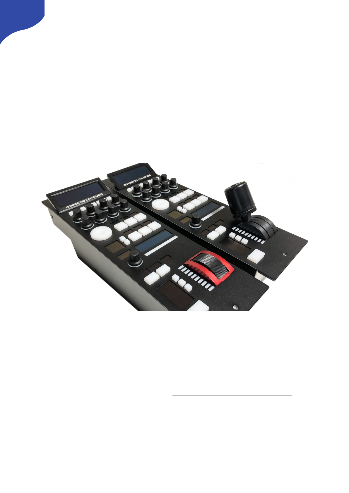
JVC Connected Cam Studio RCP
RM-LP250S
RM-LP250M
USER GUIDE | March 2020
Get the latest version of this User Guide at: https://www.skaarhoj.com/support/manuals/
1
Page 2

Contents
Important Information 3
Legal Notice 3
Warnings 3
Maintenance Precautions 3
Regulatory Compliance 3
What’s In the Box 4
Overview 4
Features 4
Controller Diagrams 5
Top - RM-LP250S 5
Top - RM-LP250M 6
Backside 7
System Configuration 8
Connection 8
Power 8
Camera Settings 9
Network Interface 9
Authentication 9
IP settings 9
Firmware 9
Controller Settings 10
IP Settings 10
Firmware Update 10
DB9 (EXT I/O) 10
Network Interface Details 11
Power over Ethernet (PoE) Specifications 11
Troubleshooting 11
Controller Use 12
RM-LP250S 12
RM-LP250M 14
Parameter Settings 15
Dimensions 16
Changing Default Configuration 17
Different Mapping of Functions 17
Changing Default Username/Password for Authentication 18
Troubleshooting 20
No iris feedback on LED Bar for RM-LP250M 20
2
Page 3

Important Information
Legal Notice
Attention:
The content and instructions of this document are
subject to change without prior notice. Updates
will be added to the manual.
Best effort have been conducted to verify the
correctness of the content in this manual, but no
statement, information, or recommendation in this
manual shall constitute formal guarantee of any
kind, expressed or implied. We shall not be held
responsible for any technical or typographical
error in this manual.
The product and graphic appearance
demonstrated in this manual is for reference only,
and may differ from the actual appearance of your
device and associated software applications.
Use of this manual and the subsequent result shall
be entirely on the user’s own responsibility.
Reference to product names of other companies
in this manual are the trademark or registered
trademark of the respective companies.
Warnings
•
If the product does not work properly, please
contact your dealer. Never attempt to
disassemble the controller yourself (we will not
assume any responsibility for problems caused
by unauthorized repair or maintenance)
•
This installation should be made by a qualified
service person and should conform to all the
local codes
•
When shipping, the controller should be packed
in its original packaging
•
Make sure the power supply voltage is correct
before using the controller
•
Do not drop the controller or subject it to
physical shock
Maintenance Precautions
•
If there is dust on the controller and the
displays, remove the dust gently using a oil-free
brush or dust blowing apparatus
•
Do not use organic solvents, such as benzene or
ethanol when cleaning the surface of the
controller
Regulatory Compliance
For private households: Information on
Disposal for Users of WEEE
This symbol on the product(s)
and / or accompanying documents
means that used electrical and
electronic equipment (WEEE)
should not be mixed with general
household waste. For proper
treatment, recovery and recycling, please take this
product(s) to designated collection points where
it will be accepted free of charge.
Alternatively, in some countries, you may be able
to return your products to your local retailer upon
purchase of an equivalent new product.
Disposing of this product correctly will help save
valuable resources and prevent any potential
negative effects on human health and the
environment, which could otherwise arise from
inappropriate waste handling.
Please contact your local authority for further
details of your nearest designated collection
point.
Penalties may be applicable for incorrect disposal
of this waste, in accordance with you national
legislation.
For professional users in the European Union
If you wish to discard electrical and electronic
equipment (EEE), please contact your dealer or
supplier for further information.
For disposal in countries outside of the
European Union
This symbol is only valid in the European Union
(EU). If you wish to discard this product please
contact your local authorities or dealer and ask for
the correct method of disposal.
3
Page 4

What’s In the Box
1 x RM-LP250M or RM-LP250S RCP Controller
1 x Power Adaptor including power plug
1 x 2m CAT.5E Ethernet cable
1 x 1m USB 2.0 Type A/Type Micro B cable
Overview
This user guide is suitable for the following
models
-
RM-LP250M
-
RM-LP250S
Features
•
Support forJVC GY- HC900 and HY-HC550
including
•
Iris control
•
Zoom + focus control (if lens supports it)
•
Master Black control
•
Gain Settings
•
AE Levels
•
Shutter mode and speed
•
WB Mode, WB One Push and WB Paint
•
Detail
•
Tally
•
Menu and Menu Navigation
•
Character Output Mix
•
Super crisp window with large display tiles for
settings
•
High-quality encoders with RGB backlight for
function identification
•
Camera ID display with OLED technology
•
RGB tally bar
•
Preview button for GPI or control of video router
•
Four-way buttons with OLED legends for
dynamic labelling and functionality
•
Pressure and direction sensitive joystick pad
•
Master black knob with dedicated OLED display
•
Classic iris joystick or encoder wheel with
display and LED bar
•
Industry standard form factor (4"/102mm wide)
•
Sits console style on table top or mountable in
OB van rack
•
Power: DC 12V, PoE (48V IEEE 802.3af )
•
Firmware Upgrade via USB2.0
•
DB9 (EXT I/O) connector
•
Option for changing configuration layout
4
Page 5
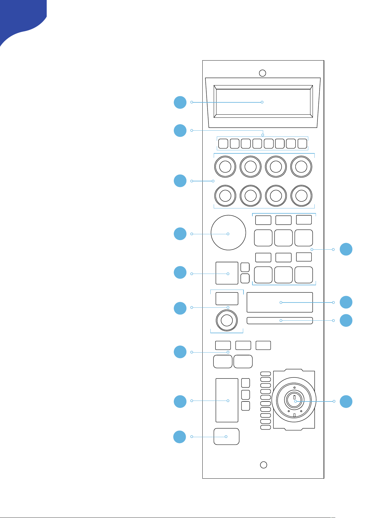
Controller Diagrams
Top - RM-LP250S
1. Large display with 8 tiles. Functions
associated with encoders from group 3
2. 8 user buttons
3. 8 rotary encoders with RGB backlight for
function identification
4. Elastomer joypad
5. Group of 6 4-way buttons with associated
displays
6. Recording + streaming buttons
with associated display
7. Camera ID display
8. Master black encoder with associated
display
9. Tally bar
10. Shift and system status
11. Joystick with master black ring and push
button
12. Iris control parameters
13. 4-way button for Preview
5
CONNECTED CAM STUDIO
1
2
3
4
5
6
7
9
8
10
1112
13
Page 6
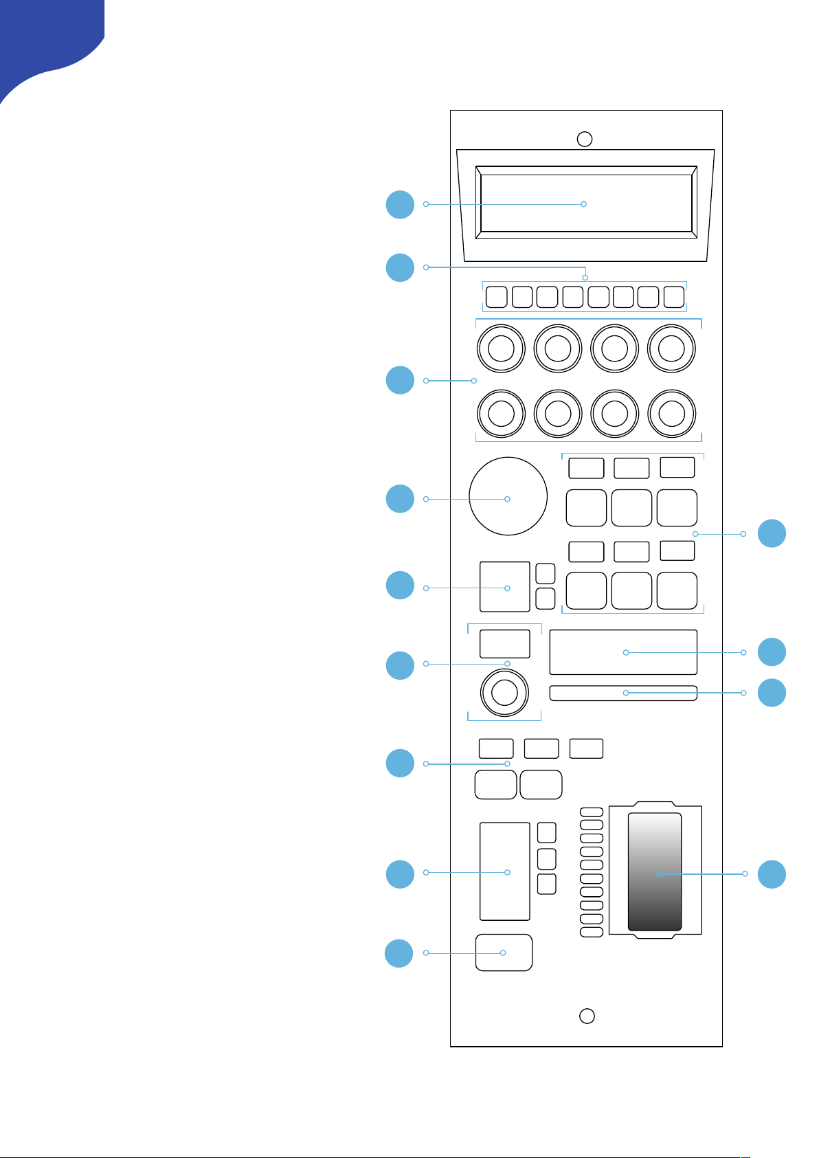
Top - RM-LP250M
1. Large display with 8 tiles. Functions
associated with encoders from group 3
2. 8 user buttons
3. 8 rotary encoders with RGB backlight for
function identification
4. Elastomer joypad
5. Group of 6 4-way buttons with associated
displays
6. Recording + streaming buttons
with associated display
7. Camera ID display
8. Master black encoder with associated
display
9. Tally bar
10. Shift and system status
11. Iris wheel
12. Iris control parameters
13. 4-way button for Preview
6
CONNECTED CAM STUDIO
1
2
3
4
5
6
7
9
8
10
1112
13
Page 7
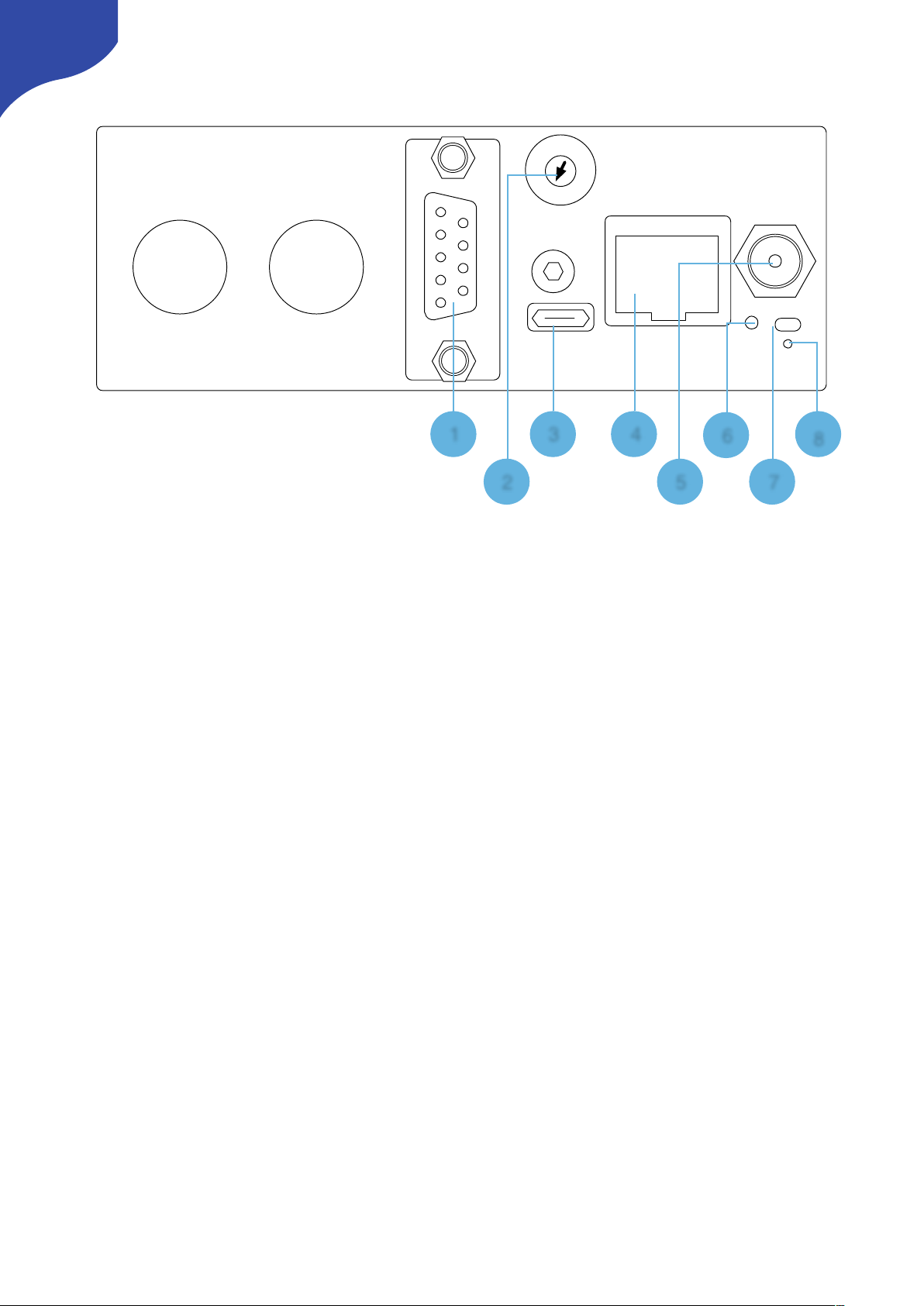
Backside
1. DB9 (EXT I/O)
For external routing/tally systems
2. Camera Selector
Used on RM-LP250S to select camera number for Camera ID display
3. USB 2.0 Port
Used for firmware upgrade and IP settings only
4. IP Network RJ45 Port
For IP Control with PoE (48V IEEE 802.3af)
5. 12V DC Power Supply
Connect the supplied DC Power adaptor
6. Status LED
For monitoring and debugging
7. Reset button
Controller reset - same as taking the power of the controller
8. Programming mode reset
Only to be used if contact with support have been established
7
0
8
4
C
1
2
3
5
6
7
9
A
B
D
E
F
245
7
8
163
Page 8

System Configuration
Connection
The RM-LP250S and the RM-LP250M
communicates to camera(s) via wired ethernet
communication. This is the supported case.
The controllers connects to the cameras and
changes settings on the camera itself. No video
signal processing are done on the RM-LP250S or
the RM-LP250M.
The RM-LP250S is designed to control one
camera.
The RM-LP250M is designed to control up to 3
cameras at the same time.
Power
•
Use only the DC power adapter supplied with the controller. Do not use any other DC power adaptor
•
If using PoE to power the controller, make sure the network switch supports PoE (48V IEEE 802.3af)
•
Ensure the PoE provider has sufficient power budget to power the controller. Otherwise it will not
function properly
•
Power Consumption: 6 Watts
8
Ethernet Ethernet
Needs to be on same subnet!
RM-LP250S
RM-LP250M
Page 9

Camera Settings
Network Interface
If the camera does not have a native ethernetport
directly on the camera body, a USB/Ethernet
adapter must be utilized from the USB2.0 HOST
port.
Authentication
Web access must be enabled on the camera with
Login Name: jvc
Login Password: skaarhoj
In order for the controllers to authenticate with the
cameras. The above login name and login
password are set by default on the controllers.
Please consult the camera manual for instructions
in setting web access.
IP settings
A static IP address must be set on the camera
Please consult the camera manual for instructions.
Firmware
The JVC GY- HC900 must have the firmware
version v0230-0217 or newer.
The JVC GY HC550 must have the firmware
version v0120-0166 or newer
9
Page 10

Controller Settings
In order to change IP or to update the Firmware
on the controller the Firmware Updater
Application is used: https://www.skaarhoj.com/
support/firmware-updater/
The application is available for PC, Mac and Linux.
IP Settings
1. Download and install the Firmware Updater
Application
2. Connect the USB cable to the controller and to
the computer. Power the controller
3. Press “IP Configuration”
4. Change IP address and press “Save Settings”
The controller reboots and will look for cameras
on the provided IP addresses.
The controller and the camera must be on the
same subnet.
Avoid having Device Cores activated which does
not connect to an actual camera.
Firmware Update
1. Download and install the Firmware Updater
Application
2. Connect the USB cable to the controller and to
the computer. Power the controller
3. Press “Check for Updates”
This generates a new firmware file and
downloads it to the controller. It will reboot
once completed.
DB9 (EXT I/O)
This is the pinout for the DB9 connector
-
When the joystick top button or the “Prev”
button is pressed, a relay is shorting pin 1 and 2
-
For RM-LP250S: If pin 8 is shorted to GND (pin
5 or 9) the RGB Tally bar will light red and Tally
will be sent to camera (Tally System must be set
to Studio on camera)
-
For RM-LP250M no tally is sent to the
cameras as the GPIO connector only have 1
input
10
Page 11

Network Interface Details
•
The controller have a 100 mbps network
interface
•
Network switch must have Auto-MDI/MDIX
•
Network switch must support 100 mbps
•
PoE: IEEE 802.3af
Power over Ethernet (PoE) Specifications
The PoE industry standard 48V IEEE 802.3af is
used. If powering the controller using PoE it is
important the network switch supports this
standard. Please notice some manufactures such
as Ubiquity have their own non-standard 24V type
of PoE which is incompatible with the controller.
Especially pay attention to the standard if using a
PoE injector.
Troubleshooting
If experiencing no network activity at all, try one or
more of the following suggestions:
•
Use a managed network switch
•
Force network switch port to 100 mbps
•
Try a different network switch
11
Page 12

Controller Use
RM-LP250S
Overall the controller have two Menus. To change
between the two menus press M1 and M2. The
controller have 1 shift level. To activate this press
M7.
C1-C8
Activate User Switch 1-8. If B13 is pressed and
hold on the upper edge, the main display is
hijacked and shows actions for C1-C8
K1-K8
The tiles in the main display are associated with
Knob 1-8
Position UD
Zoom in/out on upper/lower edge of rubber pad
if lens supports it
M1-M6
B7
Activates recording
B8
Activates streaming
ID Display
Displays “CAMERA X”where X is set via the
Camera Selector on the backside. See Backside
section.
ID Tally
Lights up white by default and red when pins on
DB9 connector is set or if Tally have been set on
the camera via other systems/via the B13 button
Black
Controls Master Black
Menu: WB/Sh
Menu: Lens
K1
WB Paint: Red
Focus
K2
WB Paint: Blue
Focus One Push
K3
WB Mode
Focus Mode
K4
WB One Push
Press and hold to activate
Detail
K5
Full Auto
Iris Mode
K6
Gain Mode
Iris
K7
Shutter Mode
Iris One Push
K8
Shutter Speed
AE Level
Shift: Off
Shift: On
M1
Sets “Menu: WB/Sh”
Sets “Menu: WB/Sh”
M2
Sets “Menu: Lens”
Sets “Menu: Lens”
M3
Full Auto
Full Auto
M4
User Switch 1
Character Mix - SDI2
Can be changed to
HDMI or video
M5
User Switch 2
Activates Menu/Status:
Up: Menu Toggle
Down: Status Toggle
Left: Menu Cancel
Right: Menu Set
M6
User Switch 3
Menu Navigation:
Up: Menu Up
Down: Menu Down
Left: Menu Left
Right: Menu Right
12
CONNECTED CAM STUDIO
C1 C2
C3 C4 C5 C6 C7 C8
K1 K2 K3 K4
K5 K6
K7
K8
M1 M2
M3
M4 M5 M6
B7
B8
ID Display
ID TallyBlack
Position
UD
K1 K2 K3 K4
K5 K6 K7 K8
Page 13

M7
Shift level via toggle
M8 Connection Status
Shows connection status. Button have no function
Iris
Displays Iris value
B9-B11
Iris range is used for calibrating the iris joystick to
match the maximums aperture open/closed
conditions for the lens. To calibrate:
Reset Points
Move joystick to fully open aperture and
set: Open
Move joystick to fully closed aperture and
set: Closed
LED Bar
Indicates Iris value
Joystick
Controls iris value
Ring
No function assigned to the joystick ring. The
camera protocol does not support setting an
absolute value for Master Black.
Button
Activates “Preview” relay on DB9 connector
B13
Shift: Off
Shift: On
B9
Active Panel. If enabled
no hardware interface will
respond
Iris Range: Reset Points
B10
Iris one Push
Iris Range: Set fully
open
B11
Iris Mode. Light up Red
when in Auto. Green
when in manual
Iris Range: Set fully
closed
Shift: Off
Shift: On
B13
Upper Edge hold down:
Hijacks main display to
show actions for C1-C8
Lower Edge hold down:
Activates “Preview” relay
on DB9 connector
Sets Tally on camera via
Toggle
13
CONNECTED CAM STUDIO
C1 C2
C3 C4 C5 C6 C7 C8
K1 K2 K3 K4
K5 K6
K7
K8
M1 M2
M3
M4 M5 M6
B7
B8
ID Display
ID TallyBlack
M7 M8
B9
B10
B11
B13
Iris
LED
Bar
- Joystick
- Ring
- Button
Position
UD
K1 K2 K3 K4
K5 K6 K7 K8
Page 14

RM-LP250M
Overall the controller have two Menus. To change
between the two menus press M1 and M2. To
change between camera 1-3 press M4-M6. The
controller have 1 shift level. To activate this press
M7.
C1-C8
Activate User Switch 1-8. If B13 is pressed and
hold on the upper edge, the main display is
hijacked and shows actions for C1-C8
K1-K8
The tiles in the main display are associated with
Knob 1-8
Position UD
Zoom in/out on upper/lower edge of rubber pad
if lens supports it
M1-M6
B7
Activates recording
B8
Activates streaming
ID Display
Displays “CAMERA 1-3” (the number associating
is set via the Memory Parameter A on M4-M6 - see
Changing Default Configuration to change this)
ID Tally
Lights up white by default and red if tally on the
cameras are set by other systems or if tally have
been enabled via button B13
Black
Controls Master Black
Menu: WB/Sh
Menu: Lens
K1
WB Paint: Red
Focus
K2
WB Paint: Blue
Focus One Push
K3
WB Mode
Focus Mode
K4
WB One Push
Press and hold to activate
Detail
K5
Full Auto
Iris Mode
K6
Gain Mode
Iris
K7
Shutter Mode
Iris One Push
K8
Shutter Speed
AE Level
Shift: Off
Shift: On
M1
Sets “Menu: WB/Sh”
Sets “Menu: WB/Sh”
M2
Sets “Menu: Lens”
Sets “Menu: Lens”
M3
Full Auto
Full Auto
M4
Cam 1
Character Mix - SDI2
Can be changed to
HDMI or video
M5
Cam 2
Activates Menu/Status:
Up: Menu Toggle
Down: Status Toggle
Left: Menu Cancel
Right: Menu Set
M6
Cam 3
Menu Navigation:
Up: Menu Up
Down: Menu Down
Left: Menu Left
Right: Menu Right
14
CONNECTED CAM STUDIO
C1 C2
C3 C4 C5 C6 C7 C8
K1 K2 K3 K4
K5 K6
K7
K8
M1 M2
M3
M4 M5 M6
B7
B8
ID Display
ID TallyBlack
Position
UD
K1 K2 K3 K4
K5 K6 K7 K8
Page 15

M7
Shift level via toggle
M8 Connection Status
Shows connection status. Button have no function
Iris
Displays Iris value
B9
Active Panel. If enabled no hardware interface will
respond
B10
Iris one Push
B11
Iris Mode. Light up Red when in Auto. Green when
in manual
LED Bar
Indicates Iris value
Iris Wheel
Controls iris value.
B13
Parameter Settings
When changing a parameter the icon illustrated
below will appear. This indicates that
communication is being sent to the camera, which
the camera is currently processing. This method
have been adopted to accommodate how the
protocol between the controller and the cameras
work.
Shift: Off
Shift: On
B13
Upper Edge hold down:
Hijacks main display to
show actions for C1-C8
Lower Edge hold down:
Activates “Preview” relay
on DB9 connector
Sets Tally on camera via
Toggle
15
CONNECTED CAM STUDIO
C1 C2
C3 C4 C5 C6 C7 C8
K1 K2 K3 K4
K5 K6
K7
K8
M1 M2
M3
M4 M5 M6
B7
B8
ID Display
ID TallyBlack
M7 M8
B9
B10
B11
B13
Iris
LED
Bar
Iris Wheel
Position
UD
K1 K2 K3 K4
K5 K6 K7 K8
Page 16

Dimensions
16
CONNECTED CAM STUDIO
35.5 cm
10.2 cm
Not to scale
4.7 cm
7.2 cm
2.3 cm
6.0 cm
24.6 cm
11.9 cm
2.3 cm
Thickness:
0.3 cm
Not to scale
Page 17

Changing Default Configuration
In some cases it can be desirable to change mapping of functionality on the diffrent hardware
components on the controller. This is presented in the following section.
If one would like to change the default username and password for authentication please see: Changing
Default Username/Password for Authentication
Different Mapping of Functions
Coming soon
17
Page 18

Changing Default Username/Password for Authentication
As mentioned in the section Authentication the default username/password for authentication is:
Login Name: jvc
Login Password: skaarhoj
This can be changed via a Device Core Options:
-
Index 0: Sets username (maximum characters = 9)
-
Index 1: Sets Password (maximum characters = 9)
-
Index 2: Sets port
Notice for the RM-LP250S and RM-LP250M the Device Core option strings have already been set on the
default configurations. This makes the procedure less error-prone.
String for RM-LP250S: D0:0="jvc";D0:1="skaarhoj";D0:2=80
String for RM-LP250M:
D0:0="jvc";D0:1="skaarhoj";D0:2=80;D1:0="jvc";D1:1="skaarhoj";D1:2=80;D2:0="jvc";D2:1="skaarhoj";
D2:2=80
Example 1:
Setting username + password could look like this device configuration code in the generic form:
D0:0=“Username”;D0:1=“Password”
A example could be
D0:0=“bryan”;D0:1=“1234567”
Where username is set to: bryan and password set to: 1234567
The general form of Device Core options are “Dx:y=z” where “x” is the number of the device core as
installed on the controller (starting with zero for the first device core), “y” the index number and “z” the
value for that index.
To confirm that a device configuration is in fact detected by the controller, please check it out on the serial
monitor where it will be mentioned:
Example: If the JVC device core is the first like below:
18
Page 19

Then setting the username + password would be set by this configuration under “Manage Media” on your
configuration page for your controller on cores.skaarhoj.com
Example 2:
Setting port could look like this device configuration code in the generic form:
D0:2=12345
To confirm that a device configuration is in fact detected by the controller, please check it out on the serial
monitor where it will be mentioned:
19
Page 20

Troubleshooting
No iris feedback on LED Bar for RM-LP250M
If the RM-LP250M do not have iris feedback on the LED Bar it could be an Iris Range issue. If the Serial
Monitor during the bootup would displays :
“Successfully recalled Limit 0 and lowr: 0 At location: 0”
And not the number 255 iris in the LED Bar will not be shown.
The iris range limitation is used to set a range for the joystick on the RM-LP250S.
In order to resolve this the action “Iris Range - Reset point” must be triggered for the impacted Device
Cores.
20
Page 21

•
Open Local Configuration via the Firmware Application (make sure your computer is on the same
network as the RM-LP250M)
•
Press “C1” and assign the following actions
JVC RCP: Iris Range - Reset points
JVC RCP #2: Iris Range - Reset points
JVC RCP #3: Iris Range - Reset points
Press “Save” and then press “C1” button on the RM-LP250M
•
Once completed open the Serial Monitor in the Firmware Application and press “Clear Presets”. This will
remove the actions just assigned to C1 (and local IP settings as well).
21
 Loading...