

Page 1

.
Thank you for purchasing this product.
Before operating this unit, please read the instructions
carefully to ensure the best possible performance.
In this manual, each model number is described without the
last letter (U/E) which means the shipping destination.
(U: for USA and Canada, E: for Europe)
Only “U” models (RM-LP100U) have been evaluated by UL.
Please read the following before getting started:
For Customer Use:
Model No. RM-LP100U
Serial No.
Enter below the Serial No. which is located on the body.
Retain this information for future reference.
REMOTE CAMERA CONTROLLER
RM-LP100U
RM-LP100E
INSTRUCTIONS
.
Specifications and appearance of this unit are subject to change for further improvement without prior notice.
Details
For details on settings and operation, refer to “INSTRUCTIONS” on the website.
Please check the latest INSTRUCTIONS, tools, etc. from the URL below.
North America:
http://pro.jvc.com/prof/main.jsp
Europe:
http://www.service.jvcpro.eu/public/
China:
http://www.jvc.com.cn/service/download/index.html
Thank you for purchasing this product.
Before beginning to operate this unit, please read the “INSTRUCTIONS” carefully to ensure proper use of the product.
In particular, please read through the “Safety Precautions” to ensure safe use of the product. After reading, store them
with the warranty card and refer to them whenever needed.
The serial number is crucial for the purpose of quality control. After purchasing this product, please check to ensure that
the serial number is indicated correctly on this product, and the same serial number is also indicated on the warranty
card.
IM 1.01
B5A-1936-00
Page 2

Safety Precautions
Cautions
The lightning flash with arrowhead symbol, within
an equilateral triangle, is intended to alert the user
to the presence of uninsulated “dangerous voltage”
within the product’s enclosure that may be of
sufficient magnitude to constitute a risk of
electric shock to persons.
The exclamation point within an equilateral triangle
is intended to alert the user to the presence of
important operating and maintenance (servicing)
instructions in the literature accompanying the
appliance.
CAUTION:
A UNIT IS A CLASS 1 LASER PRODUCT. HOWEVER THIS
UNIT USES A VISIBLE LASER BEAM WHICH COULD CAUSE
HAZARDOUS RADIATION EXPOSURE IF DIRECTED. BE SURE
TO OPERATE THE UNIT CORRECTLY AS INSTRUCTED.
WHEN THIS UNIT IS PLUGGED INTO THE WALL OUTLET, DO
NOT PLACE YOUR EYES CLOSE TO THE OPENING OF THE
DISC TRAY AND OTHER OPENINGS TO LOOK INTO
THE INSIDE OF THIS UNIT.
USE OF CONTROLS OR ADJUSTMENTS OR
PERFORMANCE OF PROCEDURES OTHER THAN THOSE
SPECIFIED HEREIN MAY RESULT IN HAZARDOUS
RADIATION EXPOSURE.
DO NOT OPEN COVERS AND DO NOT REPAIR YOURSELF.
REFER SERVICING TO QUALIFIED PERSONNEL.
MISE EN GARDE:
CET APPAREIL EST UN PRODUIT LASER DE CLASSE 1.
CEPENDANT, CET APPAREIL UTILISE UN FAISCEAU LASER
VISIBLE QUI PEUT ENTRAÎNER UNE EXPOSITON
DANGEREUSE AUX RAYONNEMENTS. S’ASSURER DE
FAIRE FONCTIONNER L’APPAREIL CORRECTEMENT, EN
RESPECTANT LES INSTRUCTIONS.
LORSQUE CET APPAREIL EST BRANCHÉ À UNE PRISE
MURALE, NE PAS PLACER SES YEUX PRÈS DE
L’OUVERTURE DU TIROIR POUR DISQUE OU D’AUTRES
OUVERTURES DANS LE BUT D’OBSERVER L’INTÉRIEUR
DE L’APPAREIL.
L’UTILISATION DES COMMANDES, RÉGLAGES OU
PROCÉDURES DE PERFORMANCE AUTRE QUE CELLE
SPÉCIFIÉE DANS CE DOCUMENT RISQUE D’ENTRAÎNER
UNE EXPOSITION DANGEREUSE AUX RAYONNEMENTS.
L’UTILISATEUR NE DOIT PAS OUVRIR NI RÉPARER
L’APPAREIL DE LUI-MÊME. FAIRE APPEL À UN PERSONNEL
QUALIFIÉ POUR L’ENTRETIEN.
AVIS
RISQUE DE CHOC ELECTRIQUE
- NE PAS OUVRIR.
CAUTION
RISK OF ELECTRIC SHOCK
DO NOT OPEN
WARNING:
TO PREVENT FIRE OR SHOCK HAZARD, DO NOT EXPOSE
THIS UNIT TO RAIN OR MOISTURE.
CAUTION:
This unit should be used withAC 120 VH, 60 Hz.
To prevent electric shocks and fire hazards, DO NOT use any
other power source.
CAUTION:
TO PREVENT ELECTRIC SHOCK, MATCH WIDE BLADE OF
PLUG TO WIDE SLOT, FULLY INSERT.
ATTENTION:
POUR ÉVITER LES CHOCS ÉLECTRIQUES, INTRODUIRE LA
LAME LA PLUS LARGE DE LA FICHE DANS LA BORNE
CORRESPONDANTE DE LA PRISE ET POUSSER JUSQU’AU
FOND.
Note to CATV system installer:
This reminder is provided to call the CATV system installer’s
attention to Article 820-40 of the NEC that provides guidelines
for proper grounding and, in particular, specifies that the cable
ground shall be connected to the grounding system of the
building, as close to the point of cable entry as practical.
“WARNING” and the following or equivalent. “To reduce the risk
of fire or electric shock, do not expose this apparatus to rain or
moisture.”
“ATTENTION” et suivant ou équivalent. “Pour limiter les risques
d’incendie ou d’électrocution, n’exposez pas cet appareil à la
pluie ou à l’humidité.”
A warning that an apparatus with CLASS I construction shall be
connected to a MAINS socket outlet with protective earthing
connection.
Avertissement: un appareil de CLASSE I doit être branché à une
prise SECTEUR comprenant une mise à la terre de protection.
When the main plug or appliance coupler shall remain readily
operable.
CAN ICES-3 A / NMB-3 A
Getting Started
.
2
Page 3
IMPORTANT SAFETY INSTRUCTIONS
1) Read these instructions.
2) Keep these instructions.
3) Heed all warnings.
4) Follow all instructions.
5) Do not use this apparatus near water.
6) Clean only with dry cloth.
7) Do not block any ventilation openings. Install in accordance with
the manufacturer’s instructions.
8) Do not install near any heat sources such as radiators, heat
registers, stoves, or other apparatus (including amplifiers) that
produce heat.
9) Do not defeat the safety purpose of the polarized or groundingtype plug. A polarized plug has two blades with one wider than
the other. A grounding type plug has two blades and a third
grounding prong. The wide blade or the third prong are
provided for your safety. If the provided plug does not fit into
your outlet, consult an electrician for replacement of the
obsolete outlet.
10)Protect the power cord from being walked on or pinched
particularly at plugs, convenience receptacles, and the point
where they exit from the apparatus.
11)Only use attachments/accessories specified by the
manufacturer.
12)Use only with the cart, stand, tripod,
bracket, or table specified by the
manufacturer, or sold with the
apparatus. When a cart is used, use
caution when moving the cart/apparatus
combination to avoid injury from tipover.
13)Unplug this apparatus during lightning
storms or when unused for long periods
of time.
14)Refer all servicing to qualified service personnel. Servicing is
required when the apparatus has been damaged in any way,
such as power-supply cord or plug is damaged, liquid has been
spilled or objects have fallen into the apparatus, the apparatus
has been exposed to rain or moisture, does not operate
normally, or has been dropped.
Failure to heed the following precautions may result in
damage to the unit, remote control or disc/cassette.
1. DO NOT
place the unit^
^ in an environment prone to extreme temperatures or
humidity.
^ in direct sunlight.
^ in a dusty environment.
^ in an environment where strong magnetic fields are
generated.
^ on a surface that is unstable or subject to vibration.
2. DO NOT
block the unit’s ventilation openings or holes.
(If the ventilation openings or holes are blocked by a newspaper
or cloth, etc., the heat may not be able to get out.)
3. DO NOT
place heavy objects on the unit or remote control.
4. DO NOT
place anything which might spill on top of the unit
or remote control.
(If water or liquid is allowed to enter this equipment, fire or
electric shock may be caused.)
5. DO NOT
expose the apparatus to dripping or splashing.
6. DO NOT
use this equipment in a bathroom or places with
water. Also DO NOT place any containers filled with water or
liquids (such as cosmetics or medicines, flower vases, potted
plants, cups, etc.) on top of this unit.
7. DO NOT
place any naked flame sources, such as lighted
candles, on the apparatus.
8. AVOID
violent shocks to the unit during transport.
When the equipment is installed in a cabinet or a shelf, make sure
that it has sufficient space on all sides to allow for ventilation
(10cm or more on both sides, on top and at the rear).
When discarding batteries, environmental problems must be
considered and the local rules or laws governing the disposal of
these batteries must be followed strictly.
Use the supplied power cord.
(If not, fire or electric shock may be caused.)
DON'T continue to operate the equipment if you are in any doubt
about it working normally, or if it is damaged in any way^switch
off, withdraw the mains plug and consult your dealer.
DO be careful with glass panels or doors on equipment.
DO consult you dealer if you are ever in doubt about the
installation, operation or safety of your equipment.
NEVER let anyone especially children push anything into holes,
slots or any other opening in the case^this could result in a fatal
electrical shock.
MOISTURE CONDENSATION
Moisture in the air will condense on the unit when you move it from
a cold place to a warm place, or under extremely humid
conditions^just as water droplets form on the surface of a glass
filled with cold liquid. In conditions where condensation may occur,
disconnect the unit’s power plug from the wall and keep it
disconnected for a few hours to let the moisture dry, then turn on
the unit.
CAUTION:
Changes or modifications not approved by JVC could void user’s
authority to operate the equipment.
Declaration of Conformity
Model Number: RM-LP100U
Trade Name: JVC
Responsible Party: JVCKENWOOD USA Corporation
Address: 1700 Valley Road Wayne, N.J. 07470
Telephone Number: 973-317-5000
This device complies with Part 15 of FCC Rules.
Operation is subject to the following two conditions:
(1) This device may not cause harmful interference, and (2) this
device must accept any interference received, including
interference that may cause undesired operation.
"This equipment has been tested and found to comply with the limits
for a Class A digital device, pursuant to Part 15 of the FCC Rules.
These limits are designed to provide reasonable protection against
harmful interference when the equipment is operated in a
commercial environment.
This equipment generates, uses, and can radiate radio frequency
energy and, if not installed and used in accordance with the
instruction manual, may cause harmful interference to radio
communications.
Operation of this equipment in a residential area is likely to cause
harmful interference in which case the user will be required to
correct the interference at his own expense."
Getting Started
.
Safety Precautions
3
Page 4

DISCLAIMER OF LIABILITY
JVC shall not be liable for any loss relating to the unit’s failure to
properly record, store or playback any content (video, audio or
otherwise) for any reason whatsoever. Any applicable warranties
shall only cover replacement or repair of the effected unit, and shall
not apply to recovery or replacement of lost content.
If this symbol is shown, it is only valid in the European
Union.
WARNING :
WARNING :
DO NOT EXPOSE THIS UNIT TO RAIN OR
MOISTURE.
The rating plate and the safety caution are on the bottom of
the unit.
DANGEROUS VOLTAGE INSIDE
TO PREVENT FIRE OR SHOCK HAZARD,
CAUTION:
When you are not using the unit for a long period of time, it is
recommended that you disconnect the power cord from the
mains outlet.
Dangerous voltage inside. Refer internal servicing to qualified
service personnel. To prevent electric shock or fire hazard,
remove the power cord from the mains outlet prior to connecting
or disconnecting any signal lead or aerial.
The mains plug shall remain readily operable.
The STANDBY/ON A button does not completely shut off mains
power from the unit, but switches operating current on and off.
ABB shows electrical power standby and ACB shows ON.
A warning that an apparatus with CLASS I construction shall be
connected to a MAINS socket outlet with protective earthing
connection.
Main Plug
The Main Plug is used as the disconnect device, the disconnect
device shall remain readily operable
Even if the display window of the unit is unlit, the main power
supply is not cut off unless the power cord is unplugged.
The main power supply for this unit is controlled by inserting or
removing the power plug.
Dear Customer, [European Union]
This apparatus is in conformance with the valid European
directives and standards regarding electromagnetic compatibility
and electrical safety.
European representative of JVC KENWOOD Corporation is:
JVC Technical Services Europe GmbH
Konrad-Adenauer-Allee 1-11
61118 Bad Vilbel
GERMANY
WARNING
This is a Class A product. In a domestic environment this product
may cause radio interference in which case the user may be
required to take adequate measures.
Sehr geehrter Kunde, [Europäische Union]
sehr geehrte Kundin,
dieses Gerät stimmt mit den gültigen europäischen Richtlinien
und Normen bezüglich elektromagnetischer Verträglichkeit und
elektrischer Sicherheit überein.
Die europäische Vertretung für die
JVC KENWOOD Corporation ist:
JVC Technical Services Europe GmbH
Konrad-Adenauer-Allee 1-11
61118 Bad Vilbel
DEUTSCHLAND
IMPORTANT:
Please read the various precautions on page 5 to 7 before
installing or operating the unit.
Note for United Kingdom power cord only
The plug of United Kingdom power cord has a built-in fuse.
When replacing the fuse, be sure to use only a correctly rated
approved type, re-fit the fuse cover. (Consult your dealer or
qualified personnel.)
How to replace the fuse
Open the fuse compartment with the
blade screwdriver, and replace the
fuse.
POWER CONNECTION
The power supply voltage rating of this product is AC 220 – 240 V
(For European countries, Asian countries, and United Kingdom).
The power cord attached conforms to the following power supply
voltage and countries. Use only the power cord designated to
ensure safety and EMC regulations of each country.
This plug will fit only into a grounded power outlet. If you are unable
to insert the plug into the outlet, contact your electrician to install the
proper outlet. Do not defeat the safety purpose of the grounded plug.
● This product should be operated only with the type of power
source indicated on the label. If you are not sure of the type of
power supply of your home, consult your product dealer or local
electric power company.
Warning:
● Do not use the same power cord for AC 120 V as for AC 220 –
240 V. Doing so may cause malfunction, electric shock or fire.
For European and Asian
countries: AC 220 – 240 V
For United Kingdom:
AC 220 – 240 V
Fuse
This equipment has been designed and manufactured to meet
international safety standards but, like any electrical
equipment, care must be taken if you are to obtain the best
results and safety is to be assured.
DO read the operating instructions before you attempt to use the
equipment.
DO ensure that all electrical connections (including the mains plug,
extension leads and interconnections between pieces of
equipment) are properly made and in accordance with the
manufacturer’s instructions. Switch off and withdraw the mains
plug when making or changing connections.
DO consult your dealer if you are ever in doubt about the installation,
operation or safety of your equipment.
DO be careful with glass panels or doors on equipment.
DON’T continue to operate the equipment if you are in any doubt
about it working normally, or if it is damaged in any way^
switch off, withdraw the mains plug and consult your dealer.
DON’T remove any fixed cover as this may expose dangerous
voltages.
DON’T leave equipment switched on when it is unattended unless
it is specifically stated that it is designed for unattended
operation or has a standby mode. Switch off using the switch
on the equipment and make sure that your family knows how
to do this. Special arrangements may need to be made for
infirm or handicapped people.
DON’T use equipment such as personal stereos or radios so that
you are distracted from the requirements of road safety. It is
illegal to watch television whilst driving.
DON’T listen to headphones at high volume, as such use can
permanently damage your hearing.
DON’T obstruct the ventilation of the equipment, for example with
curtains or soft furnishings. Overheating will cause damage
and shorten the life of the equipment.
DON’T use make shift stands and NEVER fix legs with wood screws
^to ensure complete safety always fit the manufacturer’s
approved stand or legs with the fixings provided according to
the instructions.
DON’T allow electrical equipment to be exposed to rain or moisture.
ABOVE ALL...
^ NEVER let anyone especially children push anything into holes,
slots or any other opening in the case^this could result in a fatal
electrical shock;
^ NEVER guess or take chances with electrical equipment of any
kind^it is better to be safe than sorry!
Getting Started
.
.
4
Safety Precautions
.
Page 5

.
ḏ䌰ἀ䒩㚠旑
ḏḨ⑂ᶮ䘅㚊⬴䇪岩
恩ṷ⎎䥱
㚊⬴䇪岩
摆
澐Qc澑㯟澐Ih澑
擊
澐De澑
Ṹ摭
澐Ds)WJ*澑
⢛㸵俕剰
)QCC*
⢛㸵ḍ剰愛
澐QCEF澑
乀嵰㜀久ṷ
ȵȵ ȵ ȵ
㚻䬲 ȵȵ ȵ ȵ
㴳㗷㖿䢻⯐㦢⛘
ḥ㳂廭㋣◩
ṗ旅ṷ
ȵȵ ȵ ȵ
ȵȵ ȵ ȵ
ȵȵ ȵ ȵ
䌰ἀ䒩㚠旑
㫥♿㞈埩䢻ḇᶮ⋏ḻ㮒␍♾䘅㱖⼌㇁奅⬛䘅䌰ἀ䒩㚠旑ɝ⍫夂䒩ㆸ⚩ἀ䒩㚭Ḩ⑂㕷忶
⬉㱩ゐḌ柺ᶮ䘅⎅柺奅⬛澔ṏ↷御㕦㚠⺁⥌↱㫥♿㞈㞈ⅻ䘅㚠旑ᶻ㫣澐䌰ἀ䒩㚠旑澑㕣
ᶎẛ㯢㝔䌰⠄ᶎẛḨ䒠⭺ḻỔ㚊⬴䘅䇪岩ɝ
旅ṷ␍㴉侘⾨晷ṷ䘅䌰ἀ䒩㚠旑⤃ᶌ㇁䢻澢
澐ᶎ⎍Ḩ⑂ᶮ⊆⎬䘅旅ṷ␍㴉侘⾨晷ṷᶎ䙹⎍ɝ澑
忦㌨◩ɜḥ㳂廭㋣◩ɜ䒶亇䯼澢21ⷵ
㚭埩㞽㋯!TK0U22475!䘅奅⬛亗↷ɝ
ȵ澢埩䢻学㚊⬴䇪岩⚩学恩ṷ㇁㚊⛈岩㛑㔚ᶮ䘅⎬慐⛈⚩
!
HC0U37683!奅⬛䘅旑慐夂㯃Ṧᶌɝ
澢埩䢻学㚊⬴䇪岩兴⮒⚩学恩ṷ䘅㝑ᶁ⛈岩㛑㔚ᶮ䘅⎬慐崆ⅻ
!
HC0U37683奅⬛䘅旑慐夂㯃ɝ
For RM-LP100E
GB4943.1-2011
GB9254-2008
GB17625.1-2012
Getting Started
Safety Precautions
5
Page 6

Contents
Content of this Manual
Getting Started
Safety Precautions ................................................................ 2
Getting Started
Contents ................................................................................ 6
Supplied Accessories
Main Features ........................................................................ 7
Precautions ........................................................................... 7
Name of Parts ........................................................................ 8
Preparations ........................................................................ 10
............................................................ 6
Operation
Selecting and Operating a Camera ...................................... 11
Selecting a Camera .......................................................... 11
Operating a Camera ......................................................... 11
Recording Video to the Camera ....................................... 11
Changing an Assigned Function ...................................... 12
Selecting the Position ....................................................... 12
Adjusting the Camera Functions .......................................... 13
Adjusting the White Balance (R/B Gain) .......................... 13
Adjusting Exposure Mode (EXPOSURE) ......................... 13
Adjusting the Brightness .................................................. 14
Setting the Camera Image Quality (Detail) ....................... 14
Starting the Streaming ......................................................... 14
Settings
Setup Flow ........................................................................... 15
Basic Operations of Menu Screen ....................................... 15
Menu Screen Flow ............................................................... 16
System Setup ...................................................................... 19
Switching the Camera Video Output On/Off ..................... 19
IP Setup ............................................................................... 20
Registering the IP Address ............................................... 20
Network Settings on This Controller ................................. 20
Tally Setup ........................................................................... 21
Tally Control Interface ...................................................... 21
Camera Settings Menu ........................................................ 21
Symbols used
Caution : Describes precautions concerning the operation
Memo :
A
Content of this manual
0
All rights reserved by JVC KENWOOD Corporation.
Unauthorized duplication or reprinting of this manual, in
whole or in part, is strictly prohibited.
0
Illustrated
manual are subject to change for improvement without prior
notice.
0
Other product and company names included in this
instruction manual are trademarks and/or registered
trademarks of their respective companies. Marks such as
™ and ® have been omitted in this manual.
of this product.
Describes reference information, such as
functions and usage restrictions of this product.
: Indicates the reference page numbers and
reference items.
designs,
specifications and other contents of this
Supplied Accessories
Accessories
Warranty Card (U model only) 1
INSTRUCTIONS (BASIC) 1
AC Adapter 1
Power Cord (U model: 1, E model: 2)
Wire Clamp 1
Screw (M3) 1
Others
Troubleshooting ................................................................... 22
Confirming the “OPEN SOURCE LICENSE” ........................ 22
Connection Diagram ............................................................ 22
Specifications ...................................................................... 23
.
6
Contents
Page 7

Main Features
Precautions
The features for the combination of this unit and the HD PTZ
REMOTE CAMERA (KY-PZ100) are as follows.
Simple Operation with LCD Touch Panel
Equipped with full color LCD touch panel, which makes
operation easy through its versatile screen configuration.
Operate Camera Freely with Control Lever
and Customized Buttons
Equipped with a control lever and customized buttons
assignable with
camera.
Also enables smooth pan/tilt operation.
functions, which enhances the operability of the
Control up to 100 units of HD PTZ REMOTE
CAMERA
Up to 100 units of HD PTZ REMOTE CAMERA (KY-PZ100) can
be controlled.
Storage and Usage Locations
Avoid using or placing this unit in the following
places.
It might result in malfunctions or failure.
0
or
cold places that are beyond the allowable operating
Hot
temperature range (0 °C to 40 °C (32 °F to 104°F)).
0
Locations beyond or below the allowable operating
humidity range of 20 %RH to 90 %RH. (Condensation is
not allowed)
0
Near equipment that emits strong magnetic fields, such as
transformers or motors.
0
Near equipment that emits radio waves, such as
transceivers and mobile phones.
0
Locations with excessive dust and sand.
0
Locations prone to moisture such as window side.
0
Locations that are subjected to radiation, X-rays, salt attack
or corrosive gases.
0
Places subject to smoke or vapor such as near a cooking
stove
0
Places subject to strong vibrations or unstable surfaces
In a parked car under direct sunlight or near a
heater for long hours
Protect this unit against penetration of dust
when using it in a place subject to sandy dust.
Getting Started
Handling Precautions
Do not rub against or press the surface of the
touch panel with a knife or a sharp object.
Do not apply excessive force to this unit; do not
lift this unit while holding the control lever.
Maintenance
Turn off the power before performing any
maintenance.
Wipe using a soft cloth. Wiping with thinner or
benzene may melt or tarnish its surface.
For tough stains, wipe using a cloth that is
dipped into a neutral detergent diluted with
water, followed by wiping with a dry cloth.
Cautions on Installing this Unit on a
Desktop
Install this unit such that it does not fall from the
desktop due to vibrations.
Energy Saving
When this unit is not in use, set the Power
switch to “OFF” to reduce power consumption.
Main Features
7
Page 8
Name of Parts
A
B
C
D
E
F
G
H
I
J
A B C D E F G
I
H
J
Wire Clamp
(supplied)
Screw (M3)
(supplied)
AC adapter
(supplied)
Front Panel
Getting Started
.
A
USER1 button
For switching the settings menu.
B
F1 knob
Used for the multi-function settings.
C
F2 knob
Used for the multi-function settings.
D
USER2 button
For switching the settings menu.
E
Zoom lever
For performing the zoom operation of the remote camera.
F
ALARM lamp
:
Red
G
POWER lamp
Green : Lights up while the power is turned on.
H
Control lever (F3)
0
For operating pan/tilt of the remote camera.
0
Used for the multi-function settings.
I
Focus knob/Push auto button
0
For
0
Used for the one-push auto focus function.
J
Operation panel
Used as a touch panel.
Lights up when the alarm is activated.
performing
the focus operation of the remote camera.
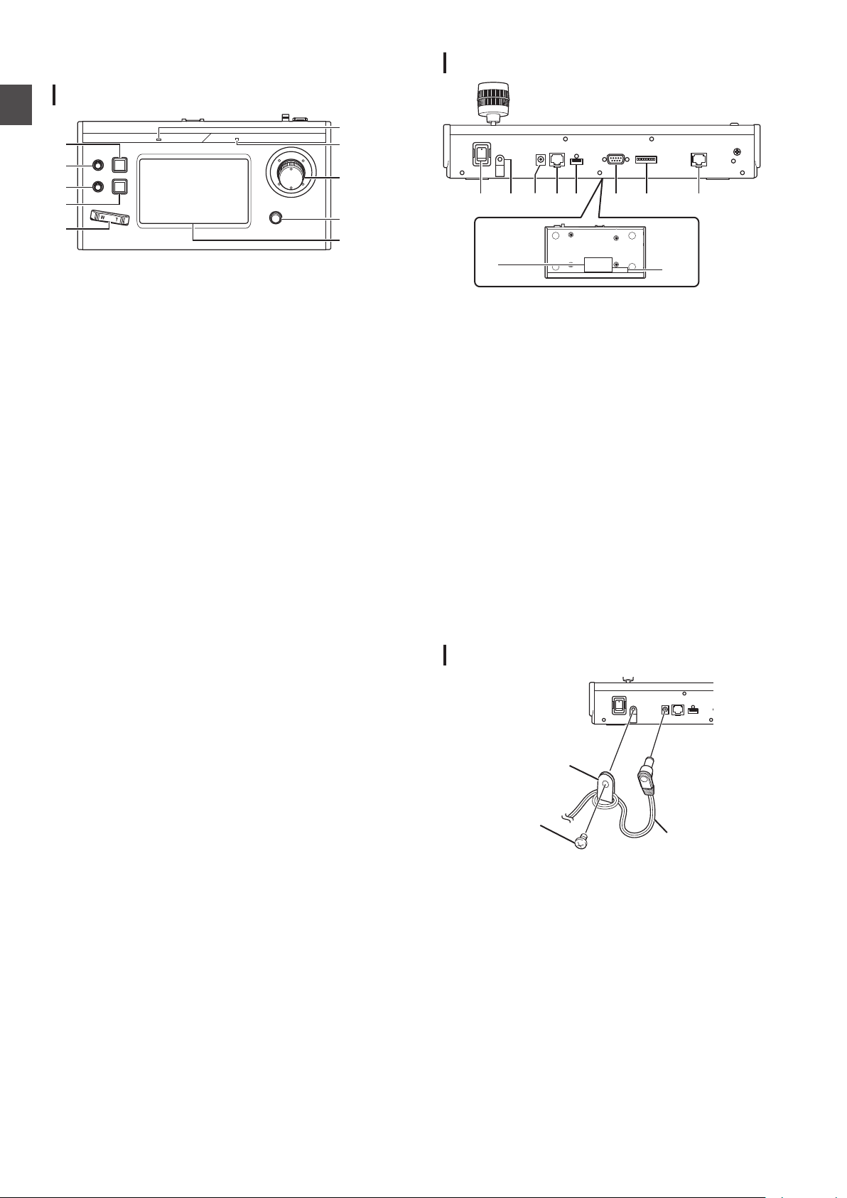
Rear Panel
.
A
Power switch
For turning the power on or off.
B
Wire Clamp
For preventing the AC adapter cable from falling out.
C
DC 12V terminal
For connecting the supplied AC adapter.
D
LAN terminal
For connecting a LAN cable.
E
SERVICE terminal
For use during servicing.
F
TALLY terminal
Used for TALLY connection.
G
SETTING switch
:
1 to 4
5 to 8 : Used for servicing only.
H
SERIAL terminal
Not used.
I
Rating label
J
MAC address label
For switching TALLY IN and OUT.
Installing the Wire Clamp
.
8
Name of Parts
Page 9

Camera Operation Screen
P
K
L
M
O
R
Q
S
N
A
B
C
E
G
I
D
F
H
T
U
J
Getting Started
.
A
[USER1]
The function assigned to the [USER1]
configured.
The default function assigned is “EXPOSURE”.
B
[F1]
The function assigned to the [F1] knob can be configured.
The default function assigned is “AE LEVEL”.
C
[F2]
The function assigned to the [F2] knob can be configured.
The default function assigned is “SPEED”.
D
[F3]
The function assigned to the [F3] lever can be configured.
The default function assigned is “NONE”.
E
[USER2]
The function assigned to the [USER2] button can be
configured.
The default function assigned is “FOCUS”.
F
[LIVE]
Tap the button to activate the presets for LIVE.
F1:AE LEVEL, F2:SPEED, F3:NONE, USER1:FOCUS,
USER2:REC
G
[EXPOSURE]
Tap the button to activate the presets for EXPOSURE.
F1:GAIN, F2:SHUTTER, F3:IRIS, USER1:EXPOSURE,
USER2:STREAMING
H
[WHITE BALANCE]
Tap the button to activate the presets for WHITE BALANCE.
F1:WB R, F2:WB B, F3:NONE, USER1:WB, USER2:AWB
TRIGGER
I
[SETTINGS]
Tap the button to display the SETTINGS screen.
button can be
J
[ENTER]
Appears
mode. Can be used to confirm and delete the position
number.
K
[VIEW]
Tap the button to enter [VIEW] mode.
L
[STORE]
Tap the button to enter [STORE] mode.
M
[DELETE]
Tap the button to enter [DELETE] mode.
N
[PT ACTIVE]
Tap the button to switch [PT ACTIVE] on and off. Switching
to off disables the pan/tilt operation by the control lever.
O
[Position Group] display
Displays the number of the position group currently selected.
P
[CAM Group] display
Displays the number of the camera group currently selected.
Q
[Position Group] tab
Tap to switch to the selection of position group number.
R
[CAM Group] tab
Tap to switch to the selection of camera group number.
S
[Position] tab
Tap to switch to the selection of position number.
T
Position/ position group/ camera group number
buttons
Allows you to select the position/ position group/ camera
group number.
U
Camera number button
Allows you to select the camera number.
when the unit goes into [STORE] mode or [DELETE]
Name of Parts
9
Page 10

Preparations
1
Set the power switch to “On”.
0
Getting Started
The power is turned on and the POWER lamp lights up.
0
The start screen is displayed on the operation panel.
The ALARM
this unit cannot be operated.
0
The start screen disappears after about 10 seconds and
the home screen is displayed.
2
Configure the settings of this unit.
0
Set the IP address of this unit as follows.
A
Select [SETTINGS] on the home screen of the
operation panel.
0
If the home screen does not appear, select
[HOME] to display the home screen.
B
Select [Network]
C
Select [CONTROLLER].
0
The IP address setting screen appears.
D
Enter the IP address and tap
3
Configure the camera settings.
0
Configure the camera to be operated as follows.
A
Select [SETTINGS] on the home screen of the
operation panel.
0
If the home screen does not appear, select
[HOME] to display the home screen.
B
Select [Network].
C
Select [CAMERA REGISTRATION].
D
Select [AUTO] to register the camera.
Memo :
0
For details on configuring using the [MANUAL]
setting, please refer to “Registering the IP
Address” (
lamp lights up at the same time. During which,
.
[ENTER]
A P 20).
.
0
or change the camera to be operated, perform the
To add
above procedures again.
10
Preparations
Page 11

Selecting and Operating a
Operating a Camera
Camera
Selecting a Camera
Specify the camera number to display the video on the monitor.
.
1
Display the home screen.
If the home screen does not appear, tap the [HOME] button
on the screen.
2
Tap the number button corresponding to the
number of the camera group to be operated.
The number of the camera group selected is displayed at the
upper right corner of the screen.
3
Tap the number button corresponding to the
number of the camera to be operated.
0
The
number
0
The digit of the number with non-existent camera within
the camera group is displayed in white.
Memo :
0
Up to 10 cameras can be configured to one camera group.
0
Up to 10 camera groups can be registered and a total of up
to 100 cameras can be configured.
button of the camera selected changes color.
Operating the PTZ (pan/ tilt/ zoom)
1
Select a camera to operate.
(A P11 “Selecting a Camera”)
2
the
Tilt
control lever toward the direction you want
the camera to move (pan/ tilt operation).
0
Tilt the
lever to the left and right to move horizontally (pan)
and tilt it up and down to move vertically (tilt).
0
To change the camera movement speed, operate the [F1]/
[F2] knobs.
(A P12 “Changing an Assigned Function”)
0
The movement
of the lever.
3
Operate the zoom lever to adjust the size of the
speed changes depending on the tilt angle
field of view (zoom operation).
0
Press the T-end of the lever to magnify the subject
(Telephoto) and press the W-end to make the subject
appear smaller (Wide-angle).
0
The zoom speed changes according to the extent the
zoom lever is being pushed.
0
By configuring
can be rotated to perform zoom operation.
(A P12 “Changing an Assigned Function”)
0
The zoom movement speed changes depending on the
angle of rotation of the lever.
“ZOOM” to the F3 function, the control lever
Performing focus operation
1
Turn the focus knob.
0
To adjust
“MANUAL” using the [USER1]/ [USER2] buttons.
Turn counterclockwise: Focus on near objects.
Turn clockwise :
the focus by turning the focus knob, set focus to
Focus on distant objects.
One push focus
Focus is automatically adjusted when you press the focus knob
while focus has been set to “MANUAL”.
Recording Video to the Camera
Operation
1
Select USER1 on the operation panel.
2
Select “REC”
in function select and tap the
[ENTER] button.
3
Tap the USER1 button to start the recording on
the camera.
4
Tap the USER1 button during recording to stop
the recording on the camera.
Memo :
0
You can also configure “REC” to the USER2 button.
0
“RECORDING” appears on the operation panel during
recording.
0
If the recording does not start even after tapping the USER1
button, check the camera setup.
Selecting and Operating a Camera
11
Page 12

Changing an Assigned Function
Operation
.
Functions assigned to F1/ F2/ F3/ USER1/ USER2 can be
changed.
The following procedure is to assign
“FOCUS
” to F1 knob.
Selecting the Position
o
Position
This system allows you to configure multiple shooting
positions on one camera. This shooting position is referred to
as “position”. The JVC HD PTZ REMOTE CAMERA
KY-PZ100 network camera allows you to configure 10 groups
by 10 patterns, a total of 100 shooting positions.
The shooting positions configured are registered as “preset
positions” and can be called up any time.
Selecting a preset position
Specify a preset number to display the video of the preset
position.
1
Select the Position Group tab and tap a group
number.
2
Select the Position tab and tap a preset number.
3
Display the video of the preset number selected.
1
Select F1 on the operation panel.
2
Select “FOCUS”
3
Select USER1 on the operation panel.
4
Select
You can switch between “AUTO” and
the USER1 button. Setting focus to “MANUAL” allows you to
adjust the focus using the F1 knob.
5
Tap the [ENTER]
Tapping the [ENTER] button confirms the selected setting
and returns the display to HOME screen. Tapping the
[HOME] button cancels the selected setting and returns the
display to HOME screen.
“FOCUS (AUTO/MANU)
in function select.
” in function select.
“MANUAL” focus using
button.
Memo :
0
The assignable functions to each button are as follows.
WB R/B
AE level
SPEED
SHUTTER
GAIN
IRIS
FOCUS
DETAIL
NONE
ZOOM
EXPOSURE
WHITE BALANCE
AWB TRIGGER
STREAMING
REC
F1/F2 F3
c
c
c
c
c
c c
c c c
c
c
c
USER1/
USER2
c
c
c
c
c
Registering a position
1
Display the home screen.
If the home screen does not appear, tap the [HOME] button
on the screen.
2
Tap the [STORE
3
Tap the Position Group tab and select a group
] button.
number.
4
Tap the Position tab.
5
Select the number to be registered and tap the
[ENTER
The current camera status is registered to the selected
position number of the position group.
] button.
Memo :
0
digit
The
0
The digit of the position group turns yellow if positions are
registered.
of the button registered with a position turns yellow.
Deleting a registered position
1
Display the home screen.
If the home screen does not appear, tap the [HOME] button
on the screen.
2
Tap the
3
Tap the Position Group tab and select a group
number.
4
Tap the Position tab.
5
Select the position number to be deleted and tap
the [
The registration information of the selected position number
of the position group is deleted.
Memo :
0
The digit of the button with the position deleted turns white.
0
The digit of the position group turns white when all positions
are deleted.
DELETE] button.
[
ENTER] button.
12
Selecting and Operating a Camera
Page 13

Adjusting the Camera Functions
Adjusting the White Balance (R/B Gain)
Changing the white balance setting
You can switch among “FAW”/ “AWB”/“3200K”/ “5600K”/
“MANUAL” using the USER1 button.
:
FAW
AWB : Automatically adjusts the white balance by
3200K : Sets the color temperature to 3200K.
5600K : Sets the color temperature to 5600K.
MANUAL : Manually adjust the R gain and B gain.
1
Select USER1 on the operation panel.
2
Select
tap the [ENTER] button.
F1 knob can be used for WB R (R gain), F2 knob for WB B
(B gain), USER1 button for WB and USER2 button for AWB
TRIGGER.
Executing AWB Trigger
Effective if white balance mode is set to “AWB”.
The white balance is automatically adjusted when the AWB
Trigger button is tapped.
Adjusting the R/B gain
Adjust the AWB Paint within the ±32 range if white balance mode
is set to “AWB”.
Adjust the R/B GAIN in the 0 to 255 range if white balance mode
is set to “MANUAL”.
Activates automatic white balance mode.
tapping the AWB Trigger button.
WHITE BALANCE” in function select and
“
Adjusting Exposure Mode (EXPOSURE)
Select method for controlling the brightness.
AUTO : Adjusts the brightness automatically.
SHUTTER : Switches to shutter priority (manual for
IRIS : Switches to iris priority (manual for iris and
MANUAL : Switches iris, gain and shutter to manual
Adjusting the iris
o
Auto iris (automatic adjustment) mode
Auto iris (automatic adjustment) mode is activated by setting
EXPOSURE to “AUTO” or “SHUTTER”.
1
Select USER1 on the operation panel.
2
Select
[ENTER] button.
3
Tap the USER1 button and select “AUTO” or
“
SHUTTER”.
o
Manual iris (manual adjustment) mode
Manual iris (manual adjustment) mode is activated by setting
EXPOSURE to “IRIS
1
Select USER1 on the operation panel.
2
Select [
[ENTER] button.
3
Tap the USER1 button and select “IRIS”
“MANUAL”.
4
Select F1 on the operation panel.
5
Select [IRIS
[ENTER] button.
The F1 knob can be used to adjust the iris.
shutter and auto for all others) operation.
auto for all others) operation.
operation.
[EXPOSURE]
EXPOSURE
function select and tap the
in
” or “MANUAL”.
] in function select and tap the
] in function select and tap the
or
Operation
Setting the electronic shutter
o
Automatic shutter mode (automatic shutter adjustment)
Automatic shutter mode (automatic shutter adjustment) is
activated by setting EXPOSURE to “AUTO” or “IRIS”.
1
Select USER1 on the operation panel.
2
Select
[ENTER] button.
3
Tap the USER1 button and select
“IRIS”.
o
Manual shutter mode (manual shutter switching)
Manual shutter mode (manual shutter switching) is activated
by setting EXPOSURE to “SHUTTER” or “MANUAL”.
1
Select USER1 on the operation panel.
2
Select
[ENTER] button.
3
Tap the USER1 button and select “
“MANUAL”.
4
Select F1 on the operation panel.
5
Select [
[ENTER] button.
The F1 knob can be used to adjust the shutter.
[
EXPOSURE]
[
EXPOSURE]
in function select and tap the
“AUTO
” or
in function select and tap the
SHUTTER” or
SHUTTER] in function select and tap the
Adjusting the Camera Functions
13
Page 14

Setting the gain
o
Automatic gain mode (automatic gain adjustment)
Automatic gain mode (automatic gain adjustment) is
activated by setting EXPOSURE to “AUTO”.
1
Select USER1 on the operation panel.
2
Select
Operation
[ENTER] button.
3
Tap the USER1 button and select
o
Manual gain mode (manual gain switching)
Manual gain mode (manual gain switching) is activated by
setting EXPOSURE to “MANUAL”.
1
Select USER1 on the operation panel.
2
Select [
[
EXPOSURE]
EXPOSURE
[ENTER] button.
3
Tap the USER1 button and select “MANUAL”
Adjusting the Brightness
o
Adjusting
adjustment (AE) mode)
Automatic brightness adjustment (AE) mode is activated by
setting EXPOSURE to “AUTO”.
1
Select F1 on the operation panel.
2
Select “AE LEVEL”
ENTER] button.
[
3
Adjust the brightness for automatic brightness
adjustment mode using the F1 knob.
o
Adjusting the brightness manually
Manual adjustment mode is activated by setting EXPOSURE
to
“MANUAL”.
brightness automatically (automatic brightness
the
in function select and tap the
AUTO”.
“
] in function select and tap the
.
in function select and tap the
Starting the Streaming
1
Select USER1 on the operation panel.
2
Select “STREAMING
the [ENTER] button.
3
Tap the USER1 button to start streaming.
4
Tap the USER1 button during streaming to stop
streaming.
Memo :
0
You can
0
A streaming icon is displayed on the operation panel during
streaming.
0
If streaming does not start even after tapping the USER1
button, check the camera setup.
also configure “STREAMING” to the USER2 button.
in function select and tap
”
1
Select F1 on the operation panel.
2
Select “AE LEVEL”
ENTER] button.
[
3
Adjust the shutter speed using the F1 knob.
in function select and tap the
Memo :
0
You can also configure “GAIN” and “IRIS” to the F1 knob.
0
“SHUTTER”,
0
“IRIS”
0
If EXPOSURE is set to “SHUTTER”, only the shutter speed
can be adjusted manually.
0
If EXPOSURE is set to “IRIS”, only the iris can be adjusted
manually.
“GAIN” and “IRIS” can be configured to F2 knob.
can be configured to F3 (control lever).
Setting the Camera Image Quality (Detail)
1
Select F1 on the operation panel.
2
Select “DETAIL” in function select and tap the
[
ENTER] button.
3
Adjust the camera image quality (contour
enhancement level) using the F1 knob.
Memo :
0
You can also configure “DETAIL” to the F2 knob.
14
Adjusting the Camera Functions
Page 15

Setup Flow
Basic Operations of Menu
When setting up the system for the first time, or when new
cameras are added, set up in the manner as follows.
Be sure to perform an operation check after the setup.
1
IP address settings
Configure the IP address of the connected device.
20 “IP Setup”)
(A P
2
Camera setup
Set up the connected camera.
(
A P21 “Camera Settings Menu”)
3
Remote control settings
Configure the functions assigned to the customized buttons
of this unit.
A P
(
12 “Changing an Assigned Function”)
Screen
1
Tap the
The settings menu appears.
2
Select the item to be configured.
Settings Menu
o
VIDEO
Allows you to switch the video outputs of the connected
cameras on or off.
(A P19 “Switching the Camera Video Output On/Off”)
o
MENU Control
Allows you to display and operate the settings menu of the
selected camera.
(A P21 “Camera Settings Menu”)
o
Function
Allows you to configure the settings for this unit.
0
Touch Screen Volume
Allows you to configure the operation sound of the operation
panel.
0
Brightness
Allows you to configure the brightness of the operation panel.
0
Power Save
Allows you to configure the duration of time before this unit
enters into power save mode.
Power save mode is disabled while the settings menu is
displayed.
0
Default Setting
Allows you to restore the default settings of this unit.
When the [Default Setting] button is tapped, the color of the
button changes to yellow. Tap the [ENTER] button in this
condition and then turn off the power to restore the default
settings.
0
Setting Data<->USB
Allows
vice versa.
Connect the USB drive to the SERVICE terminal on the rear
panel of this unit.
Memo :
0
Format the USB drive with FAT32/16 in advance. This unit
does not support formatting.
0
Version Information
The version of this unit is displayed at the bottom right of the
Function screen.
o
Network
Allows you to configure settings related to the network.
(A
P20 “Network Settings on This Controller”)
o
Touch Screen
Allows you to calibrate the operation panel.
Tapping the [
screen. Operate according to the on-screen instructions.
SETTINGS] button on the home screen.
[
you to write the settings of this unit to a USB drive and
Touch Screen] button displays the adjustment
Settings
Setup Flow
15
Page 16

Menu Screen Flow
Home Screen VIEW Screen CAM Group Screen
Position Group Screen
Position Screen
Home Screen STORE Screen CAM Group Screen
Position Group Screen
Position Screen
o
menu
The
below.
Normal Menu Screen
VIEW Screen
Allows you to select the camera and the preset position of the camera.
Settings
screens consist of normal menu screen and settings menu screen. The flow of the each screen is as shown in the figures
.
STORE Screen
Allows you to register the preset position of the camera.
.
16
Menu Screen Flow
Page 17

DELETE Screen
Home Screen DELETE Screen CAM Group Screen
Position Group Screen
Position Screen
Home Screen F1/F2 Screen (*)
USER1/USER2
Screen (*)
* You can adjust the function that is
highlighted without tapping [ENTER]
while the screen is displayed.
F3 Screen (*)
Home Screen
Allows you to delete the preset position of the camera.
.
Settings
F1/F2/F3/USER1/USER2 Screen
For assigning functions to the buttons and knobs of this unit.
.
Menu Screen Flow
17
Page 18

Settings Menu Screen
Home Screen
SETTINGS Screen
Video Screen
MENU Control Screen
Function Screen
Network Screen
Touch Panel Screen
ALL CAMERAS Screen
CAMERA Group Screen
Single Screen
CAMERA Screen
CONTROLLER Screen
SETTINGS Screen
For configuring the settings of this unit.
(A P15 “Settings Menu”)
Settings
.
18
Menu Screen Flow
Page 19

System Setup
Switching the
Setting the video outputs of all cameras on/off
1
Display the home screen.
If the home screen does not appear, tap the [HOME] button
on the screen.
2
Tap the
The settings menu screen appears.
3
Tap the
4
Tap the
5
Tap the
0
0
6
Tap the [ENTER
Setting the video outputs of camera groups on/
off
1
Display the home screen.
If the home screen does not appear, tap the [HOME] button
on the screen.
2
Tap the [SETTINGS
The settings menu screen appears.
3
Tap the [Video]
4
Tap the [CAMERA Group
5
Tap the number button of the camera group and
the
0
0
6
Tap the [ON] or
0
0
7
Tap the [ENTER
[SETTINGS] button.
[
[
[
Tapping the button changes the button color.
Tap the [ON] button to set the video output of the camera
to on.
Tap the [OFF] button to set the video output of the camera
to off.
number
Multiple camera groups can be selected.
The digit of the number with non-existent camera within
the camera group is displayed in white.
Tapping the button changes the button color.
Tap the [ON] button to set the video output of the camera
to on.
Tap the [OFF] button to set the video output of the camera
to off.
Camera Video Output On/Off
Video] button.
ALL CAMERAS] button.
ON] or [OFF] button.
button to confirm the setting.
]
button.
]
button.
button.
]
button of the camera to be configured.
[OFF] button.
button to confirm the setting.
]
Setting the video output of individual camera
on/off
1
Display the home screen.
If the home screen does not appear, tap the [HOME] button
on the screen.
2
Tap the [SETTINGS]
The settings menu screen appears.
3
Tap the [Video]
4
Tap the [Single]
5
Tap the number button of the camera group and
the
number
6
Tap the [ON
0
Tapping the button changes the button color.
0
Tap the [ON] button to set the video output of the camera
to on.
Tap the
to off.
7
Tap the [ENTER
button of the camera to be configured.
] or [OFF] button.
[OFF] button to set the video output of the camera
Memo :
0
Only cameras in the selected camera group can be
configured.
0
[ALL CAMERAS] can be configured to “ON”/“OFF” only for
cameras within the same network.
0
To control the Video output of a camera that is not within the
same network, use CAMERA Group or Single.
0
When the video output of a camera is turned off, you will not
be able to control the camera.
button.
button.
button.
button to confirm the setting.
]
Settings
System Setup
19
Page 20

IP Setup
Registering the IP Address
Settings
.
1
Display the home screen.
If the home screen does not appear, tap the [HOME] button
on the screen.
2
Tap the [SETTINGS]
The settings menu screen appears.
3
Tap the [Network]
4
Tap the [CAMERA REGISTRATION
5
Tap the [AUTO
0
Tapping the [AUTO] button automatically configures the
camera network settings. (Recommended)
After the “Completed
[CLOSE] button to complete the configuration.
The subsequent operation procedures are not required.
Tapping the [MANUAL] button displays the manual settings
screen for IP address.
6
Register the IP address manually.
0
Change the [CAM Group] and [CAM No] to select the
camera that you want to register the IP address.
0
Enter the IP address using the numeric keypad.
0
Tap the [ENTER] button to confirm the numbers entered.
0
Configure all
procedures.
Memo :
0
This is a function to register the IP address of the camera to
this unit. The IP address of the camera unit cannot be
changed even when performing manual registration by
selecting [MANUAL].
0
Use the same Port No. and Password as configured on the
connected camera.
The factory default is configured according to the factory
default setting of the JVC “KY-PZ100
0
If configuring
the connected devices within the network in sequence from
“***.***.***.100”. And there are no functional problems even
when the IP address of the device is duplicated.
0
If more than one of this unit is connected within the same
network, only up to five units can assign IP address using
“AUTO”.
0
Configuring the
of that camera.
or [MANUAL] button.
]
the cameras to be registered using the same
using “AUTO”, this unit assigns IP addresses to
IP address to “0.0.0.0” deletes the registration
button.
button.
button.
]
” message is displayed, tap the
” network camera.
Network Settings on This Controller
.
1
Display the home screen.
If the home screen does not appear, tap the [HOME] button
on the screen.
2
Tap the [SETTINGS
The settings menu screen appears.
3
Tap the [Network]
4
Tap the [CONTROLLER] button.
The network settings screen of this unit appears.
5
Enter each item and tap the
Memo :
0
The default IP address of this unit is 192.168.0.2.
button.
]
button.
[ENTER
] button.
20
IP Setup
Page 21

Tally Setup
1ON2345678
1
6
5
9
1ON2345678
1ON2345678
1ON2345678
1ON2345678
RM-LP100
LED
TALLY OUT
GND
(Maximum voltage 24 V)
(Maximum current
50 mA)
+5 V
TALLY IN
S
D
G
RM-LP100
GND
Tally Control Interface
Configure the pin 4 and pin 5 functions of the tally terminal using
the SETTING switch on the rear panel.
Other than pin 4 and pin 5, the remaining pin functions cannot
be changed.
.
Memo :
0
If a camera has been selected to receive tally signals, the
button corresponding to the camera appears like .
Configuration method
Tally terminal pin
number
1 INPUT-1 2 INPUT-2 3 INPUT-3 4 INPUT-4
Function SETTING switch
Connection example for TALLY OUT
Please ensure the following conditions are met.
Voltage :
Current : Maximum 50 mA
.
Maximum DC 24 V
Connection example for TALLY IN
Set up the contact input.
.
Settings
.
OUTPUT-5
.
5 INPUT-5
.
OUTPUT-4
.
6 GND 7 OUTPUT-1 8 OUTPUT-2 9 OUTPUT-3 -
Memo :
0
The tally input or tally output supports camera number 1 to 5
of camera
the cameras to these numbers. For details on the tally input
and tally output, refer to the “Function” column of
"Configuration method".
0
Inserting and removing of the tally terminal should be
performed while the power is turned off.
group 1. To use the tally input or tally output, assign
Camera Settings Menu
Making changes to the settings menu of the
camera
1
Tap the
the operation panel.
0
0
2
Tap the [
screen.
3
Tap the [
0
0
4
Tap the
0
Memo :
0
For details on making changes to the settings menu of the
camera,
0
When removing the camera from the network, delete the
camera registration as well.
0
If the IP address of the camera is changed, communication
may fail for a while even when the IP address has been
changed through the camera registration of this unit. In that
case, turn off the power.
[SETTINGS] button on the home screen of
The settings screen appears.
If the home screen does not appear, select [HOME] to
display the home screen.
MENU Control] button on the settings
MENU] button.
The settings menu of the selected camera is displayed on
the video output from the camera.
Use the control lever and the [ENTER] button to change
the settings.
HOME] button.
[
After changing the settings, tap the [HOME] button to
return to the home screen.
please
refer to the instruction manual of the camera.
Tally Setup
21
Page 22

Troubleshooting
RM-LP100
KY-PZ100
KY-PZ100 KY-PZ100
LAN cable
HUB
Problem Symptom Action
Power does
not turn on.
No response even
after tapping the
operation panel on
the unit.
Turn off the power switch at
the back of the unit and
power on again. If it still
does not
the unit, disconnect the
power cord from the power
outlet and consult a dealer
or our service center.
Confirming the “OPEN
Others
SOURCE LICENSE”
start up, stop using
1
Select [
SETTINGS] on the home screen of the
operation panel.
0
Tapping the button displays the [SETTINGS
0
If the home screen does not appear, select [HOME] to
display the home screen.
2
Select “Open Source License”
on the
] screen.
“SETTINGS” screen.
0
The “Open Source License” screen appears.
Connection Diagram
.
* Up to 100 cameras can be connected concurrently.
* Communication system of this unit
Normal
communication
ALL CAMERAS : Multicast (239.0.255.255)/ UDP/
CAMERA Group/
Single
Memo :
0
“ALL CAMERAS”/
[SETTINGS] in the [Video] screen.
:
The TCP/destination port number is
dependent on the menu settings
destination port number 80
: UDP/ destination port number 80
“CAMERA Group”/ “Single” are options for
22
Troubleshooting
Page 23

Specifications
350
182
110
62
177
General
Item Description
Power DC 12 V
Current consumption 0.6 A
Mass Approx. 2.1 kg
Surrounding
temperature
Allowable operating
humidity
0 °C to 40 °C (32 °F to 104 °F) (operation)
20 %RH to 90 %RH (No condensation)
Accessories
Accessories
Warranty Card (U model only) 1
INSTRUCTIONS (BASIC) 1
AC Adapter 1
Power Cord (U model: 1, E model: 2)
Wire Clamp 1
Screw (M3) 1
Terminal Section
Item Description
TALLY terminal D-sub 9-pin
LAN terminal 10BASE-T/100BASE-TX
[DC] terminal DC jack (for the supplied AC adapter)
Dimensional Outline Drawing (Unit: mm)
.
* The specifications and appearance of this product are subject to changes for further improvement without prior notice.
Others
Specifications
23
Page 24

RM-LP100U/RM-LP100E
REMOTE CAMERA CONTROLLER
© 2016 JVC KENWOOD Corporation
B5A-1936-00
 Loading...