

Page 1
JVC
MODEL
taL-Fe
QUARTZ
TURNTABLE
FULLY AUTOMATIC
No. 2464
. FEB. 1979
Page 2
Contents
1. Specifications ...................................................................
2. ServicePrecautions................................................................
Features.......................................................................
4. NamesofPartsandTheirFunctions.....................................................
5. Replacement Procedures
(1) Stylus..................................................................
Headshell "
(2)
(3) Cartridge..............................................
(4) Motor..................................................................
(5) HO/VODampingKnobs "
6. Lubrication
(1) HO/VODampingMechanism ..................................................
(2) Motor..................................................................
(3) FullyAutomaticMechanism...................................................
7. Adjustment Procedures
(1) ~UARTZ LOCK/PITCH CONTROL Meter ........................................
(2) OuartzLockAdjustment
Tonearm Section
(3) HeadsheliAngle "
(4) TonearmElevator..........................................................
(5) Overhang ...............................................................
(6) Lead-in.................................................................
(7) Lead-out................................................................
(8) TrackingForce...........................................................
(9) Anti-skating.............................................................
(10) HO/VODamping .........................................................
F6BlockDiagram .............................................................
8. OL-
9. Troubleshooting Charts
Platter does not rotate.
(1)
Platter rotates at high speed. .................................................
(2)
Pitch Control operates abnormally. .............................................
(3)
10. Exploded Views and
10-(1) Cabinet & Mechanism Ass
10-(2) Mechanism Ass
10-(3) TonearmAss
11. Printed Circuit Board Ass
11-(1) MDC-938G .............................................................
11-
(2) TPS-206 ...............................................................
12. Accessories List .................................................................
13. OL-
14. PackingMaterialsandPartNumbers....................................................
15. Parts List with Specified Numbers for Designated Areas. .
F6 Schematic Diagram ..........................................................
Parts List
y and Parts List
..................................................... 8
Back page
Pages
'" 6
OL-
No. 2464
1 -
Page 3
Specifications
MOTOR SECTION
(These specifications apply only to the quartz lock mode.
Motor
Servo system
Drive system
Speeds
: Core less
FG servomotor
: Phase-
oscillator
: Direct drive
: 33-
, DC type
locking to the quartz
1/3
Fine pitch
adjustable range
Wow and flutter
to-noise ratio
Signal-
Speed detection
Starting torque
Speed deviation
Load characteristics
Drift
Power characteristics
: :!: 6 % (at the pitch
: 0.
025 % (WRMS)
: More than 78 dB (DIN-
control mode)
: Frequency generator
: More than 1.
: Within 0.
2 kg-cm
002 %
: 0 % (with 170 g total tracking
force)
: 0.0001 %/H
: 0 % (:!: 10 V)
Temperature
characteristics
Platter
TONEARM SECTION
Type
: 0.
00005
7 cm
: 32.
: Statically-
%tc
balam;ed oil-damped
tonearm
Effective arm length
Overhang
Weight range
including headshell
: 233 mm
: 15 mm
: 13 - 20 g
24 g (when using the provided
sub-counterweight)
CARTRIDGE SECTION
(Except for USA, Canada and U.
Type
Frequency response
: Moving magnet (MD-l025EB)
: 10 Hz - 25 000 Hz
Output : 3 mV (1 kHz)
Channel separation
Load resistance
Compliance
Stylus
Optimum tracking force: 1.
GENERAL
Power consumption
Dimensions
Weight
Accessories
EP adapter
Sub-counterweight
: 25 dB (1 kHz)
(using the test record TRS-
: 47 - 100 k-ohms
: 10 x 10
30 x 10
: DT-
(diamond
6 cm/dyne (dynamic)
6 cm/dyne (static)
Zl EB
, 0.3 x 0.7 mil.
, elliptical)
75 g :!: 0.
25 g
: 15W
: Height 14.
cover)
Width 45.6 cm
Depth 40.
(Since the dimensions show only
the design measurements
sideration is requ
installing the unit in a limited
space such as a rack
: 11 kg (without the packaging)
: 1
Place the adapter on the center
spindle when playing a record
having a bigger diameter center
hole such as a doughnut record.
: 1
2 cm (with closed
0 cm
, con-
ired when
, etc.
2. Service Precautions
. Be sure to use JVC standard parts.
. When
. Be sure to adjust motor speed with the u nit level
. When repairing circuit board with the heat sink
repairing the speed control circuit board con-
nect the m938
to the transistor used.in the platter drive section.
G motor in order to prevent damage
otherwise fluctuations which make adjustment impos-
sible may occur.
, attach mobile heat-sink to prevent the tran-
moved
sistor temperature from rising.
re-
Design and specifications subject to change without notice.
3. Features
. Newly developed oil-damped tonearm
trackability.
Highly sensitive, new gimbal'support tonearm system.
. Double-
resonance coreless motor give high reliability.
. Extra-
the mat
Howling margin is greatly
super-compound (type-
quartz servo circu it and high torque
heavy aluminum diecast platter (2 kg including
, inertia 330 kg/cm
improved with the new
l) board used as the base.
Operation buttons and controls are positioned at the
front for easy operation.
. NR-
type headshell with minimum
ployed.
Moving-magnet cartridge with a elliptical stylus.
Fine pitch control allows adjustment
(approx. a half note).
. Quartz lock/Pitch control meter for convenient speed
check.
Fully automatic mechanism.
assures high
, non-
resonance is em-
within:!: 6 %
QL-
No. 2464
Page 4
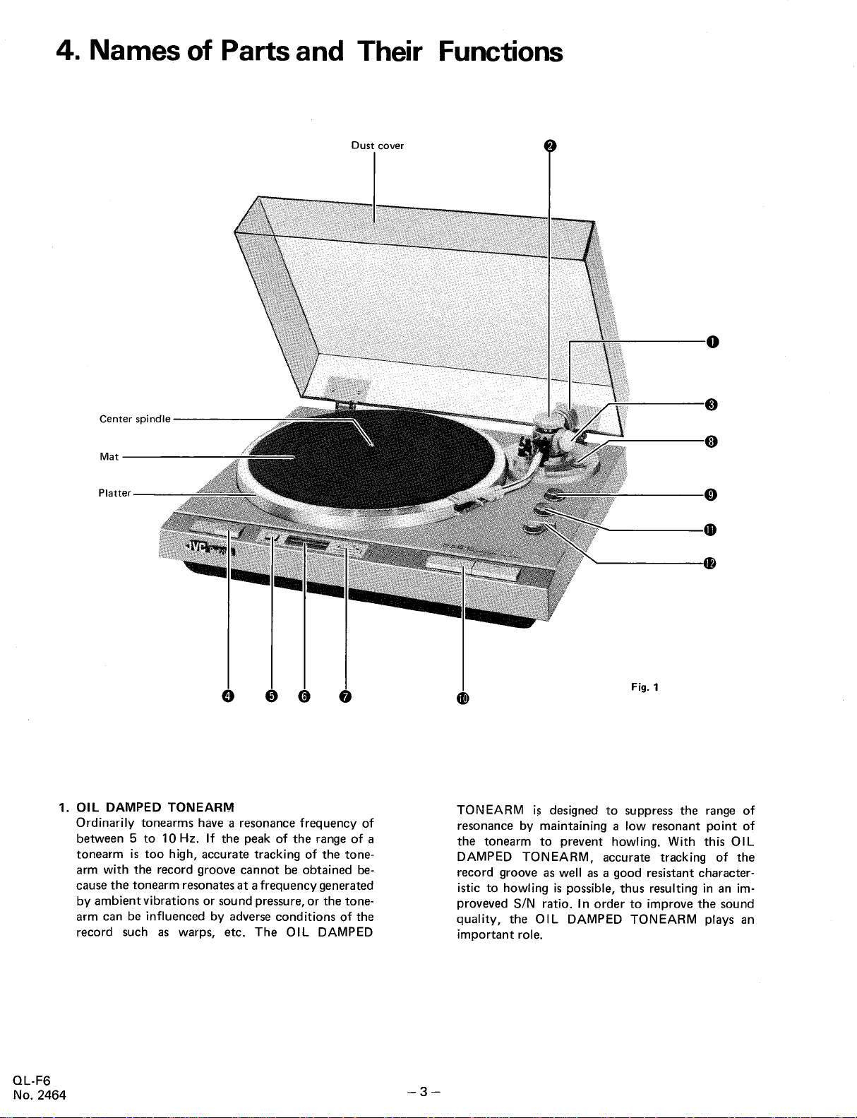
4. Names of Parts and Their
Dust cover
Center spindle
Mat
Functions
Platter
1. OIL
DAMPED TONEARM
Ordinarily tonearms have a resonance frequency of
between 5 to 10Hz.
tonearm is too high
arm with the record groove cannot be obtained be-
cause the tonearm resonates at a frequency generated
If the peak of the range of a
, accurate tracking of the tone-
by ambient vibrations or sound pressure, or the tone-
arm can be influenced by adverse conditions of the
record such as warps
, etc. The
OIL DAMPED
Fig. 1
TONEARM i~ designed to suppress the range of
resonance by maintaining a low resonant point of
the tonearm to prevent howling. With this OIL
DAMPED TONEARM
, accurate tracking of the
record groove as well as a good resistant character-
istic to howling is possible
proveved SIN ratio. I
quality, the OIL
DAMPED TONEARM plays an
, thus resulting in an im-
n order to improve the sound
important role.
QL-
No. 2464
Page 5
2. HQ
DAMPING knob
This controls the horizontal movement of the tone-
arm while aiding to keep the tonearm
s resonating
point low. Set the knob to the same indication
ber as the optimum tracking force of this unit.
3. VQ
DAMPING knob
This controls the vertical movement of the tonearm
while aiding to keep the tonearm
low. Set the knob to the same
the optimum tracking force of this unit.
4. Speed
select knob
s resonating point
indication number as
Select a proper position of the speed select
accordance with the rpm of the record.
1/3 rpm record (LP)
33-
45rpmrecord(EP).............
5. QUARTZ
QUARTZ LOCK:
Depress the button to the
speed in the quartz lock mode. In this case
meter lights green.
PITCH CONTROL:
Depress the button a second time to obtain
P ITCH CO NT RO L position (---) in order to
form fine pitch adjustment for the sound meeting
your preference. I
6. PITCH
When the QUARTZ
select button is set to the QUARTZ LOCK position
the meter is green-
When the QUARTZ
select button is set to the
tion
the PITCH
orange-
7. PITCH CONTROL knob
Fine pitch
QUARTZ
set to the PITCH CONTROL position. Pitch
ment
deflecting to the left (#)
cates an increase to the accurate 33-
and the deflection to the right (b) means a decrease.
8. ANTI-
This device cancels out the centripetal force that
pulls the tonearm to the center of the platter. This
prevents the stylus tip from skating toward the
center of the platter and at the same
any excessive stylus tip force on the inner
the record groove. Use the 8 marked dial when
ploying a spherical stylus. Use the marked dial
when employing an elliptical stylus or a SHIBATA
stylus.
Turn the dial to the
force dial.
LOCK/PITCH CONTROL select button
QUARTZ LOCK position
) for playing a record at an accurate rotation
n this case, the meter I ights orange.
CONTROL meter
LOCK/PITCH CONTROL
lit and the indicator displays "
LOCK/PITCH CONTROL
PITCH CONTROL posi-
, pitch control can be
performed by turning
CONTROL knob and the
I it.
#6 % means +6 %
% means -
b6
control can be performed with the
LOCK/PITCH CONTROL select button
range is
SKATING knob
6 %
:!: 6 %. The
indicator in the meter
from the center (0) indi-
1/3 or 45 rpm
time eliminates
same number as on the track ing
num-
knob in
33"
45"
, the
the
per-
meter is
adjust-
wall of
em-
REPEAT knob
9.
Decide how many times you want to re-
record by using this knob.
When you set the knob
listen to the
to " , the record will continue to play repeatedly.
Note: This knob cannot be
1 - 0 or 0 - 1
pressed with the power cord
from the outlet. For this
in the section "
to record playing
10. START/REJECT buttons
When you start playing a record
ST ART
button. The
the position of the first groove of the
selected and gently lowers itself onto the surface of
the record to play it.
record, depress the REJECT button. The
, returns automatically to its rest and the platter
lifts
stops rotating.
, however, the
number of repeats
respond ing number
REPEAT knob has been set for a
, the tonearm
of prepeats before the platter
stops rotating.
Note: When the dial of the repeat
numbers other than "
set to
continues to rotate and the
be turned off even though you depress
turned to indicate from
if the START button is de-
disconnected
, refer to the note
Necessary procedures prior
" on page 2.
, depress the
tonearm moves automatically
When you stop playing the
performs the cor-
knob has been
, the platter
power will not
REJECT button or even if the
record has
power to be turned off after the
played once
to the "0" mark.
RECORD SIZE select knob
11.
Set the knob to the corresponding
size of the record before you play it.
30 cm diameter record. . . .
25 cm diameter record. . . .
17cmdiameterrecord...... "
12. Arm lifter lever
This is
used when you want to
gently or gently lower it.
UP" position
when you pull it to the "
be lowered down gently onto the record surface.
finished. When you want the
, be sure to set the repeat knob
position to the
17"(7")
raise the tonearm
When you push it to the
, the tonearm will be lifted up,
DOWN" position
record pre-
tonearm
the
playing
record has
30" (12"
25" (10"
and
, it will
QL-
No. 2464
Page 6
5. Replacement Procedures
1)
5-(
Replacement of the stylus can be
inserting the stylus plug (A) into the
cartridge. Service life of the stylus
unit (DT-
ing on the record condition (dirty record groove etc.
Stereo LP record (30 cm) . . . Approx. 300
Stylus are disposable items. Therefore, it is recommended
to buy a supply of styli when you buy the unit.
purchasing them
Stylus
Stylus replacement (See Fig. 2)
easily made by simply
jack (B) of the
employed for this
Zl EB) is generally as follow; varying, depend-
- 500 hours
When
, specify the DT-Zl EB (JVC standard).
5-(2) Headshell
Removal and mounting of the headshell (See Fig. 3)
Turn the connector nut in the direction of "
the headshell from the tonearm. Turn it in the direction
A" to remove
of "B" for mounting the headshell.
5-(3) Cartridge
Mounting the cartridge (See Fig. 4)
1. Remove the 2 screws securing the cartridge onto the
headshell.
nstall your cartridge onto the
2. I
headshell provided or
onto a headshell of your selection.
3. The
headshell lead wires are color-coded as follows
connect them correctly.
White(+)
L Red(+).......
BlueH " " LE Green(-
4. Mount the
and leave the set screws slightly loosened
completing the "
tighten them firmly. After this adjustment
that the conditions concerning the 3 adjustments on
page 5 and 6 are satisfactorily met.
5. After each cartridge replacement, be sure to perform
the 4 adjustments described on page 9.
cartridge properly onto the
, then, after
Overhang adjustment
" (See page 9)
headshell
, be sure
(4) Motor
Green: to RE or R- of cartridge
Blue: to LE or L- of cartridg
Red: to R+ or R of cartridge
White: to L+ or L of cartrige \
Fig. 2
Fig. 3
, ~s~"'-
Cartridge
with stylus
Headshell
lift "0"
Fig. 4
How to remove the motor (Fig. 5)
Remove the motor in
no need to remove the mechanism
the following sequence. There is
s base.
1. Remove the stopper, main gear and spring
to the motor plate.
2. Disconnect the plug connecting the motor with the
speed control circuit board.
3. Remove the
4. Lift the trip lever as shown in the figure while taking
4 screws securing the motor.
care not to deform it and remove the motor while
tilting it.
5. Mount the motor, in the reverse order.
QL-
No. 2464
attached
Fig.
Page 7
(5) HQ/VQ
Damping Knobs
When replacement of VQ or HQ damping knob becomes
necessary, do it in the following sequence.
. How to replace the HQ damping knob (Fig. 6)
1. Remove the 2
screws securing the HQ damping knob
and remove the knob.
2. Turn the HQ controller clockwise until it
stops.
3. Clamp the tonearm to its rest.
4. Mount the new
troller with the
with the index line. Secure it with the 2
5. After replacing it
the section "
. How to replace the VQ damping knob (Fig. 6)
Replace in the same
replaced.
HQ damping knob on the HQ
indication "
, perform adjustment
How to use
way as the HQ
3" on the knob
" on page 4.
damping knob is
con-
aligned
screws.
referring to
6. Lubrication
6-(1) HQ/VQ
QL-F6 turntables are completely adjusted at the factory
prior to shipment. The
repaired imd it is
it malfunctions.
Damping Mechanism
damping mechanism cannot be
recommended that it be
replaced if
Ha damping knob
Ha controller
Index line
va controller
Screws
"t.
Fig. 6
va damping knob
6-(2) Motor
The motor needs no lubrication.
6-(3) Fully Automatic
Apply high quality grease to connecting and sliding parts
after they are replaced.
Mechanism
7. Adjustment Procedures
Servo-motor Control
7 -(
1)
QUARTZ LOCK/ PITCH
How to use the QUARTZ
meter (See Fig. 7-
LOCK/PITCH CONTROL
Section
CONTROL Meter
QUARTZ LOCK (~):
When the QUARTZ
button (1) is
the meter (2) becomes green-
tion speed is
depressed to tbe QUARTZ
accurately controlled by phase-
LOCK/PITCH CONTROL select
LOCK position
lit. In this mode the rota-
locking to
the quartz oscillator frequency. This means that correct
1/3 or 45 rpm is
33-
obtained. The indicator (2) of the
meter displays "
PITCH CONTROL
When performing fine pitch adjustment
QUARTZ
to the PITCH
comes orange-lit. In this mode
can be performed by
knob (3) within a
the (+) direction (counterclockwise)
Turning it in the (-)
rpm. The meter
LOCK/PITCH CONTROL select button (1)
CONTROL position and the meter be-
, fine pitch adjustment
turning the PITCH CONTROL
range of
indication of +6 % (#)
:!: 6 %. Turning the
direction (clockwise) decreases the
, depress the
knob in
increases the rpm.
shows the re-
produced sound raised by approximately a half tone.
The -6 %
(b) indication shows the
reproduced sound
is lowered by approximately a half tone.
By making these adjustments
, record sound reproduc-
tion meeting your preference can be obtained.
Fig.
QL-
No. 2464
Page 8
How to make
should indicate incorrectly (when the meter
display "
Fig.
adjustments if the pitch control meter
0" in the
QUARTZ LOCK operation). (See
does not
1. Disconnect the power cord from the outlet.
2. Remove the
3. Turning the "
platter from the motor shaft.
0" position adjusting screw clockwise
moves the indication to the right.
Turning this screw counterclockwise
cation to
Generally, there is no
tl:1e-left.
need for adjustment since
moves the indi-
proper adjustment has been performed at the factory.
Should the
indication of the meter be incorrect
adjust it in the manner above.
Adjustment of the FINE
PITCH CONTROL
meter (See Fig. 7-
Perform this meter adjustment referring to the
below after making mechanical adjustments pertaining
items
to rpm or repairing the meter circuits.
1. Function of the variable
1) VRl
(4.7k.Q):
resistors used
Connected in series with the meter and controls
the current flowing into the meter. Used to adjust
the full-scale deflection
(:1: 6 %)
of the meter.
2) VR2 (4.7k.Q).
Employed for
indicate the center position "0" at 33-
or 45 rpm.
3) VR4 (47 k.Q):
There is no need to
because of the automatic
ever, adjustment in the following order is
sary after the motor is
repaired. Turning VR4 to the right
seen from the circuit board
and turning it to
increases the speed and
unlocked
Adjust VR4 to
adjusting the pointer of meter to
1/3 rpm
adjust this variable resistor
adjusting system. How-
neces-
replaced or the circuit is
(clockwise) as
decreases the speed
the left (counterclockwise)
unlocks it. When it is
platter rotation becomes unstable.
its middle position where the
rotation speed is stable and does not increase
or decrease.
4) VR5 (22 k.Q):
For adjusting the oscillation frequency of the
pitch control. Adjust V R5 (to
position) with the speed
until the correct speed is obtained.
5) VR6 (10k.Q):
Pitch control located on front panel.
For detail
, see PITCH CONTROL on page 6.
selector set to "33-1/3"
near its middle
Fig.
2. Adjustmerrt method (See Fig.
7-C)
Perform mechanical adjustment for the meter to indicate
the center position before connecting to an AC outlet
for electrical adjustment.
1) Adjustment of the
oscillation frequency of the non-
stable multivibrator
Connect a
frequency counter to TP-
l with the
QUARTZ LOCK/PITCH CONTROL select button
while set in the
PITCH CONTROL position. Turn
VR5 with VR6 set to near the center position until
a frequency counter re
ading of 172.
8 kHz obtained.
2) Center indication adjustment of the meter.
Turn VR2 with the speed select knob set to 33-
until the meter
, set the speed select to
Then
indicates the center position "
45 rpm and the meter
1/3
indicates the center position "
Confirm again that the meter
tion at the 33.
3) Full-scale deflection
1/3 rpm.
(:1: 6 %)
Turn VR6 until an oscillation frequency of 183.
(+6 %) is obtained. Turn VRl until
indicates center posi-
adjustment
2 kHz
the meter correct-
ly indicates +6 %.
Turn VR6 until an oscillation frequency of 162.4 kHz
(-6 %) is obtained and confirm that the meter correct-
Iy indicates -6 %. Deflection of the meter out of the
-6 % zone
indicates -6 %, if the meter deflection is insufficient
for -6 %. I n this condition
out of the +6 % zone may occur
. The meter adjustment can be performed
stroboscope
is allowable. Turn VR 1 until the meter
, deflection of the meter
, but is allowable.
using a
, even
if measuring equipment
is not
available. Turn VR5 with VR6 set to the center posi-
tion until the stroboscope appears
the center indication adjustment
manner as when
employing a frequency counter.
It is not possible to perform the full scale
adjustment and adjustment of VR 1 is
stationary. For
, follow the same
deflection
unnecessary.
QL-
No. 2464
7 -
Page 9
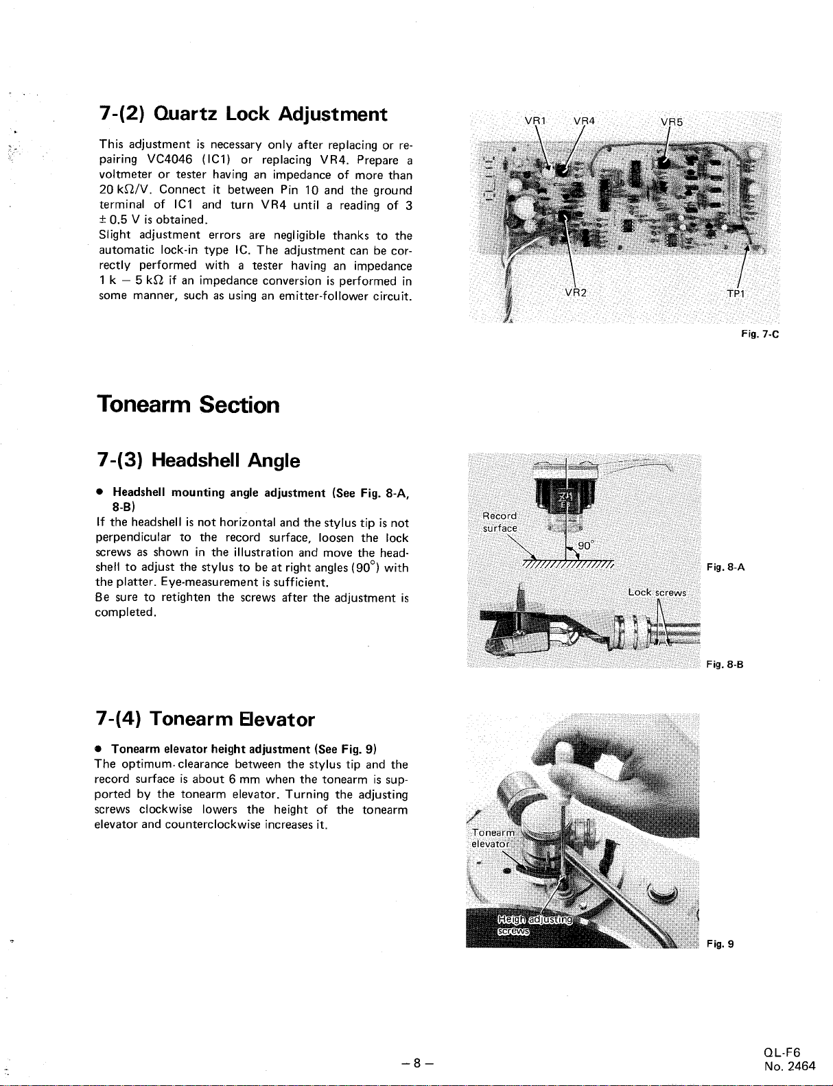
(2) Quartz Lock Adjustment
This adjustment is
pairing
VC4046 (IC1) or
voltmeter or tester having an
20 kD,/V . Connect it between Pin 10 and the ground
terminal of ICl and turn VR4 until a
:1: 0.
5 V is obtained.
Slight adjustment errors are
automatic lock-
rectly performed with a
1 k - 5 kSt
some manner, such as using an emitter-
necessary only after replacing or re-
replacing VR4. Prepare a
impedance of more than
reading of 3
negligible thanks to the
in type IC. The
adjustment can be cor-
tester having an
impedance
if an impedance conversion is performed in
follower circuit.
Tonearm Section
7 -(3)
If the headshell is not horizontal and the stylus tip is not
perpendicular to the record surface
screws as shown in the
shell to adjust the stylus to be at right angles
the platter.
Be sure to retighten the screws
completed.
Headshell Angle
Headshell mounting angle adjustment (See Fig. 8-
, loosen the lock
illustration and move the head-
with
Eye-measurement is sufficient.
after the adjustment is
(90
Fig.
Fig.
7-(4) Tonearm 8evator
. Tonearm
The optimum. clearance between the stylus tip and the
record surface is about 6 mm when the tonearm is
ported by the tonearm elevator. Turning the
screws clockwise lowers the
elevator and counterclockwise increases it.
elevator height adjustment (See Fig. 9)
sup-
adjusting
height of the tonearm
Fig.
Fig. 9
QL-
No. 2464
Page 10

7-(5) Overhang
. Overhang
obtain optimum overhang, when mounting the
To
cartridge
that of the headshell and position the
the distance between the headshell'
adjustment (See Fig. 10)
, first align the cartridge s longitudinal axis to
cartridge so that
s end face and the
stylus tip equals 48 mm.
Be sure to tighten the set
Errors within 1
point of view.
mm are negl
screw after the adjustment.
igible from a practical
7 -( 6) lead-
Stylus lead-
Your QL-
stylus lead-
, if the stylus lead-
ever
cartridge changes
1. Place a 30 cm record on the platter.
2. Set the record
operate the turntable in automatic play.
3. Confirm if the
4 mm inward from the outermost edge of the record
disc.
4. If the lead.
the adjustor screw with a
increase the distance between the lead-
the outermost edge
the distance. Thus determ
tion point to be about 3 to 4
disc edge.
in position adjustment (See Fig. 11)
F6 was shipped from the JVC factory with its
in position adjustment made properly. How-
in position is changed due to
, etc., adjust it as in the following:
size select knob to "
stylus lead- in position is about 3 to
in position is not in the proper range
screwdriver clockwise to
, and counterclockwise to decrease
ine the proper lead- in posi-
30" (12"
in position and
mm inward from the
Fig. 10
) and
, turn
Fig. 11
7-(7) lead-out
Stylus lead-out adjustment (Fig. 12)
Be sure to perform this adjustment after replacing the
tonearm, motor or related mechanism.
1. Use a 17 cm (7") record (with a lead-out groove
diameter of about 110 mm).
2. Remove the platter from the motor shaft. Turn the
adjustor screw accessible through the hole shown in
the figure clockwise with a - screwdriver to increase
lead-out tuning.
3. Confirm the
record with its inter-band track as near to the inner-
most groove as
incorrect, re-adjust, it by
screw.
QL-
No. 2464
lead-out position with a
possible. If the lead-out position is
turning the adjustment
17 cm (7")
Fig. 12
Page 11

7-(8) Tracking Force
Fig. 13
Fig. 14
Fig. 15
Fig. 16
1. Tracking force adjustment
1. Turn the
the "
anti-skaing knob until
0" mark is
aligned with the
index line. (See Fig. 13)
2. Turn the HQ
the "
0" mark is al igned with the
damping knob until
index line. (See Fig. 6)
3. Turn the VQ
the "
0" mark is aligned with the
index line. (See Fig. 14J
4. Place a disc on the platter.
5. Remove the
stylus. (See Fig. 15)
6. Release the tonearm clamp. (See
Fig. 16)
7. Zero balance adjustment (See
17)
damping knob until
stylus cover from the
Turn the counterweight until the
tonearm is balanced. Stop turning
the counterweight when the stylus
tip is almost touching the
surface.
8. Return the tonearm to the
and clamp it.
9. Hold the
adjusted position and turn the
tracking force dial until the "
mark is
line on
shaft. (See Fig. 19)
10. Turn the counterweight
direction until the "
on the
index
means an optimum tracking force
of 1.75 g is
Fig. 20)
Note:
Turning the counterweight in the
direction A decreases the tracking
force and
tion B. Turning the dial only, has
no effect on the tracking force.
counterweight at the
aligned with the index
the
tonearm
dial is aligned with the
line. The "
being applied. (See
increase it in the direc-
weight
in the B
75" mark
75" mark
Fig. 17
Fig. 18
Fig.
disc
rest
Fig. 19
Fig. 20
10 -
QL-
No. 2464
Page 12

7-(9) Anti-skating
Anti-skaing adjustment
Adjust the anti-skaing force accord ing to the cartridge
being used. Turn the anti-skating knob dial to the same
number on the tracking force dial. Use the 8 marked dial
when employing a spherical stylus. Use the
dial for an
of the - marked dial to the index
F6 is provided with an elliptical stylus and the track-
QL-
ing force has been adjusted to 1.75 g. (See Fig. 21)
7 -( 10) HO/VO
elliptical or a Shibata stylus. Set the "
Damping
marked
75"
line since the
Fig. 21
Turn the HQ
control knobs until the "
aligned with the index line
force for this unit
damped function turn the knobs
damping control and the VQ
75" marks on the dial are
, since the optimum tracking
is 1.75 g. When not
until the "
using the oil-
0" mark is
damping
aligned with the index line. (See Fig. 22)
Caution:Turning the HQ and VQ damping control knobs
while playing a record may cause damage to the
disc or to the stylus
tip. Do not touch
them
while playing a disc.
Release the tonearm clamp and start playing the record.
8. OL-
F6 Block Diagram
Platter
AC Amp.
Schmitt circuit
1----
Push-
pull
drive circuit
F /V conversion
!+24V
Mono-multi
vibrator
Fig. 22
Meter drive
circuit
+6% -
QL-
No. 2464
AC 100V
50/60Hz
DC amp.
Power
supply
circuit
+24V
+ 8V
GND
L_-
P/D circuit
Oscillator/
Frequency
divider
r- -
Speed selection
QUARTZ LOCK/PITCH CONTROL selection
Non-stable
multivibrator
11 -
Pitch control
Tal
5.5296MHz
Fig. 23
Page 13

transistors
from electronic
t disconnect the motor
in drive circuit may be damaged.
circuits while troubleshooting as
discon-
R68 are
Check if C22
open.
Observe the FG
output and IC4
performance to
trase the defect.
No. 2464
QL-
Check all driving
coils.
Yes
Note: Don
, and
elements
, HG2.
X1 - X12
Hall
HG1
Check transistors
IC5 is defective.
Replace.
Yes
Is R70
nected or badly
soldered?
Yes
Yes
IC1 is defective.
Replace
Perform locking
adjustment or
check the phase.
Yes
X16 is defective.
Fig. 24
Cooo,ct
R,p""
Yes
Replace the pilot
lamp.
Yes
dis-
Check the trans-
former for
connected wires
and damaged
printed pattern.
Check X15, 02.
is defective.
Yes -+/ X17
12 -
not rotate when
Turntable does
start button is
depressed.
1. Turntable does not rotate.
9. Troubleshooting Charts
9-( 1) Platter does not rotate
Page 14

QL-
No. 2464
X 16 is defective.
Replace.
grounded
of R30
When the terminals
, R31
stop?
, does rotation
, R32 are
base of X16 to +24 V
Does connecting the
stop rotation?
(2) Platter rotates at high speed.
Platter rotates at high speed.
when the start button is
depressed.
Rotates at high speed
Fig. 25
Yes
X17 is defective.
Replace.
Check the Schmitt cir-
cuit and AC
sections
output of motor.
, and the FG
amplifier
Yes
waveform present at
Pin 7 of IC4?
I s rectangular
Yes
shown in the circuit
diagram present at
Is the waveform
Pin 4 of IC1?
13 -
Note: Don t disconnect the motor from
Check if C22
circuits while troubleshooting as this
damage the transistors in the drive circuit.
are disconnected.
Replace if they are.
, R6
, R68
electronic
tive
Check if
may
Replace if necessary.
, VR4 is open.
, R67 is disconnect-
IC1 is defec-
Yes
Yes
IC5 is defective.
Replace.
Page 15

Yes
Check if R12 is dis-
connected. Replace if
disconnected.
Readjust and observe.
is dis-
Check if R53
so.
connected. Replace if
No. 2464
QL-
short-
short-
The collector and emit-
ter of X 19 are
circuited. Replace this
transistor .
is dis-
Check if R52
connected. Replace if
defective.
Yes
Fig. 26
de-
Is D6 or D7
circu ited? Replaced.
abnormally.
Pitch control functions incorrectly.
(3) Pitch Control operates
is dis-
open. Replace
Check if R64
X22 is
if necessary.
connected and whether
if the meter leads are
Check for disconnected
wire(s) in the meter
whether VR1 is open or
disconnected.
Yes
to positive side and remains there.
2. Meter deflects
Disconnected or
fective R 11. Replace.
Readjust and observe
this
are short-cir-
Collector and emitter
of X 18
cuited. Replace
transistor.
14 -
Page 16

9::1-
179171::
0 L
(L)-
18 :a.au!q~
(j/;-
- 9L-
sSV ws!ue4:)all\l
pue SMa!J\ papoldx3 .
:a.S!l s:a.Jed
Page 17

No. Parts Number
See table below.
E65588-
001
E49447-
004
E66140-
001
E35480-
002
E35869.o01
G4942-
G4942-4
E22873-
001
E22911.o01
OSP221 0-
E65912-
OVD7A2B-
E61713-
35981-
Ol.P3201-
E04353E04353-
059
001
014 V. Resistor
003
001
1240
001
002
LPSP3008ZS
F2001
SBSB3008Z
SBSB2608Z
E65714-
001
E65715-
003
See table below.
E60331-
005
M938G
See table below.
DPSP3008ZS
E35915-
002
E65718-
001
E22876-
003
E65282-
001
E65283-
001
REE1200
E60912.o01
E65719-
001
See page 21
E35838.o01
E35839-
001
E35839.o01
E65726-
001
REE3000
E65876-
001
E65875-
001
Descrip~ion
Motor Board Ass
Lock Plate
Shaft
Rubber Sheet
Mark
Fittings
Speed Nut
Panel
Base
Push Switch
Knob
VR. Knob
Meter Ass
Lamp
Color Cap (Green)
Ass
(Blue)
y Screw
Mechanism Base Ass
Tapping Screw
Knob
Lever Knob
Tonearm Ass
Screw
Motor Ass
Servo Control P
Screw
Stopper
Spring
Main Gear Ass
Engagement Pawl
Lawer Trip Pawl
E. Ring
Speed Nut
Connect. Rod
Fuse P
Push Knob Ass
B. Ass
Push Knob (START)
(REJECT)
Pivot
E. Ring
Leaf Spring
Rod Holder
B. Ass
No.
Parts Number
E65729-
E35841E65730E35842E35842E65733-
REE2000
E65735-
E35844-
See table below.
See table below.
SBSB4008Z
E49631.o03
E49633-
See table below.
E50670.o05
E03724-
OM LOO02-
See table below.
See table below.
E60090-
OSRO085-
E65329.o01
OSE2235-
E66153-
E61284-
E35845.o01
GBGB3012M
See table below.
E65877-
E65878-
E22874.o01
See table below.
E35828.o01
E10298-
E61992.o05
SDSP3010RS
REE4000
REE3000
LPSP3008ZS
E66154.o01
E66089.o01
001
001 Push Knob Ass
001
001
Start Rod
Bracket Ass
Push Knob (33 rpm)
002
Description
0~H
001
001
Pivot
E. Ring
Reject Rod
Trans. Bracket
Shield Cover
Power Transformer
Tapping Screw
001
Rubber Bushing
Motor Holder
Rubber Sheet
Wire Clamp
002G
051
003
001
Signal Cord Ass
Lug Strip Ass
Power Cord Ass
Cord Bushing
Shield Cover
Voltage Selector (for U.
Mil itary Market and other
countries only)
Holder
203BS
001
001
Seesaw Switch
Weight
Tapping Screw
Bottom Cover Ass
Tapping Screw
001
001
Foot Ass
Latch
Pin
Turntable
Turntable Sheet
001
Dust Cover Ass
Dust Cover
Hinge Ass
Screw
E. Ring
Ass
y Screw
Rubber Sheet
Caution Label
(45 rpm)
Parts List with Specified Numbers for Designated Areas
Item
No.
Motor Board Ass
Tonearm Ass
Servo Control
Fuse
C101
Capacitor &,
Fuse (Primary) &,
Fuse (Secondary)
Fuse CliP&'
Shield Cover
Power
Transformer &,
Rubber Sheet
Power Cord&'
Cord Bushing
Foot Ass
Turntable Sheet
Description
C. Board Ass
C. Board Ass
E 1
0302.004
ARM-
529
MDC938G-
TPS-
206B
OFH72BM-473M
OMF61 U1-
5 A)
(0.
OMF61U1-
(1A)
E45524.o01
E03032-
33B
OMP1200-
OHS3876-
E65893.o02
E22936.o02
R50
1RO
200
162
Canada
E 1
0302.004
ARM-
529
MDC938G-
TPS-
206C
OFA72BM-
OMF61U1-
(0.5 A)
OMF61U1-
(1A)
E45524.
001
E03032-
33B
aMP 1200-
OHS3876-
E65893-
002
E22936.o02
473M
R50
1RO
200
162
Europe
E 1
0302.004
MP-
201S
MDC938G-
TPS-
OFZ9007-
OMF51A2-
(0.2 AT)
OMF51 A2-
(0.
E48965-
E65716.o01
E03032-
E61796.o03
OMP3910-
A37897
E65893.o01
E22936.o01
16 -
206E
104
R20
R80
8AT)
002 E48965-
33C
244
E 10302-
003 E 1
ARM-
529
MDC938G-
TPS-
206GBS
OFZ9007-
OMF51A2-
OMF51A2-
(0.2 AT)
(0.
8AT)
104B~
R20BS
R80BS
002
E65716.o01
E03032-
33CBS
E61796.o03
OMP9017.o07BS
A37897BS
E65893-
001 E65893.o01
E22936.o01
Australia
0302.004
MP-
201S
MDC938G-
TPS-
206F
OFZ1007-104
OMF51A2-
(0.
2 AT)
OMF51A2-
(0.8AT)
E48965.o02
E65716.o01
E03032-
33C E03032-
E61796.o03
OMP2500-
200
A37897
E22936.o01
S. Military
Market and
Other Countries
E 1 0302-
MP-
201S
MDC938G-
TPS-
206D
OFH53AM-
R20 OMF60S1-
(0.5 A)
OMF60S1-
R80
(0.
8A)
E45524.o01
E65716.o01
E61796.o03
OMP1200-
A37897
E65893.o01
E22936.o01
002
104
R50
R80
33D
200
QL-
No. 2464
Page 18

10-(2) Mechanism Ass
C(ID
QL-
No. 2464
Parts Number
No.
E22883-002
E60395-001
E60394-003
E60392-O02 Switch Plate
E60393-
002
G4942-
E65740-O01 Spring
E35851-
001
E35850-O01
E60398-O01 Lead-
E65741-
001
E60912-001 Speed Nut
E60399-
001
E65742-O01
E60400-O02 Idler Gear
E60405-003 Sub Gear Ass
E60402-
002
E60403-O01
E60912-001 Speed Nut
E60404-001 Spring
E65744-O01
E65745-001 Spring
E60912-001 Speed Nut
E65746-O01
E65747-001 Spring
Description
Base Ass
Reset Plate
Switch Plate Ass
Switch Lever
Speed Nut
Dr. Gear Ass
Driving Gear
I n Lever
Push Lever
Spring
Sub Gear
Hook
Ratchet Cam
Start Lever
17 -
Parts Number
No.
E65748-
001
E60416-
001
E35852-001
E60426-
003
E60427-001 Spring
E65873-O01
E65749-O01 Select Lever
E60488-001 Spring
G41505-O05
E60390-002
E 65874-
00 1 Spring
REE3000X
E65750-O01 Cueing Shaft
E49608-
002
E60414-
001
E65956-
001
E65957-O01
E65958-O01
E65959-
001
E65960-O01
SBSB3010Z
E65720-O01 Trip Lever Ass
E65959-
002 Washer
E65959-O01
Description
Lock Lever
Spring
Index Lever
Lever
Select Plate
Steel Ball
Elevator Cam
E. Ring
Spring
Rod
Cueing Ass
Cueing Base
Cueing Lever
Washer
Spring
Tapping Screw
Page 19

10-(3) Tonearm Ass'
102-16
110
110-3
III
112~ c.
113
102-II
102-12--j 'r (
110
-2 . .
~~IIO-'
Yi
~I
~l
1\
/105
d:.~
110-4 0
Jl~
~1
107 "
t!:r~
I"~
~1C
0;&
1)~
106 102-15~"-..
( "'-3
I \
(j) I
Ei
10213
106 /
I 1
/J~
i QI6U ~
\ C)
\ "'102-191
I / -
101-5 I I
1 I
101
103 )i
eY
I~/
6!
\1
,!J
102-18 \
102-14 '
'r /
~02
"1 ~
1 ~1'l
~ i
102-19
104
102-17
~102
102-3 \
1",--i--
~!Ye
~102-7
\ ~7 i--
~1--!--102-9
, I!r
102-4
102-5
L ~
102-6
102-8
--1--102-10
No.
101
101-
101-
101-4
101-
102
102-
102-
102-4
102-
102-
102-
102-8
102102-
102-
102-
102102102-
Parts Number
E22901-
001
E35894-
TCS2002NS
E35895-
TRS2006NS
E22902-
E10308-O01
35897-001
E35900-
E49602E35901E65825E65827-
65826-
SBSB2608Z
E65829-
E49649-
E61194-
E49655-
REE3000
001
001
001
001
002
001
001
001
001
001
001
001
007
Description
Tonearm Ass
Cap (A)
Screw
Cap (B)
Screw
Tonearm Base Ass
Tonearm Base Sub Ass
Plate
Anti-skating Knob
Wave Washer
Anti-skating Lever
Anti-skating Plate
Anti-skating Spring
Spring Holder
Tapping Screw
Elevator Ass
Spring
Elevator Shaft
E" Ring
18 -
No.
102102102102-
103
104
105
106
107
108
109
110
110-
110-
110-4
110-
111
112
113
Parts Number
E65835-
001
E65824-
SBSB2616Z
SBSB2605Z
E65837E65830-
E300015-O01
SPSP3006ZS
E61775-O01
E65823-
E65938-
E35991-
E35989-
E60501E60502-
E22962-
MD-
DT-Z1EB
E34268-
001
001
001
001
001
002
002
005
001
001
1025EB
001
Description
Screw
Rest Ass
Tapping Screw
Washer
Nut
Tonearm Lever
Screw
Shield Tube
Counterweight Ass
Subweight
Headshell Ass
Finger
Wire Ass
Screw
Headshell Boay .
Cartridge
Stylus
Stylus Covering
QL-
No. 2464
Page 20

11. Printed Circuit
Board Ass y and Parts
List
11-(1) MDC-
(Different in Different Area
see back page)
938G
QL-
No. 2464
19 -
Page 21

Transistors
No,
Parts Number
2SD794(P
2SD794(P
2SD794(P
2SD794(P
2SA733(P
2SA733(P
2SA733(P
2SA733(P
2SB605(K
X10
2SB605(K
X11
2SB605(K
X12
2SB605(K
X13
2SC2259(G
X14
2SD325V(D
X15
2SC945(P
X16
2SA733(P
X17
2SC945(P
X18
2SC945(P
X19
2SC945(P
X20
2SC641K(B
X21
2SC641K(B
X22
2SC945(P
X23
2SC945(P
X24
2SC945(P
X25
2SC945(P
X26
2SC945(P
X27
2SC945(P
I ntegrated Circuits
No. Parts Number
IC1
VC4046
IC2
NJM78L08A
IC3
MSM4001
IC4
NJM4558D-
IC5
NHM4558D
Diodes
Parts Number
WO2
RD5.
6EKVM2
VC1220
15553
15553
1S953(A
1S953(A
D11
15553
Capacitors
No.
Parts Number
QCF11HP-
QET41VR-
QCT05UJ-
QCY41HK-
QET41HR-
QET41ER-
QET41HR-
C10
QEN41EA-
C11
QEN41EA-
C12
QET41ER-
C13
QET41JR-
C14
QET41JR-
C15
QET41JR-
C16
QCT05UJ-
K)
K)
K)
223
330
475
474
336
336
476
107
476
477
330
Q)
Q)
Q)
Q)
L)
L)
L)
K)
K)
K)
K)
K)
106
102
105
Q)
Q)
F)
C)
10W
250 mW
800 mW
10W
250 mW
100 mW
250 mW
Rating
Rating
022 Jl.F
10 Jl.F
33 pF
1000 pF
1 Jl.F
7 Jl.F
0.47 Jl.F
33 Jl.F
47 Jl.F
100 Jl.F
47 Jl.F
470Jl.F
33 pF
Rating
180 MHz
120 MHz
8MHz
250
180 MHz
250 MHz
400
250
Description
Description
Silicon
Zener
Varistor
Silicon
Rating
DC 50 V
DC 25 V
DC 50V
DC 25V
DC 63 V
DC 50 V
55 MHz
MHz
MHz
MHz
DC 50 V
DC 35 V
Description
Maker
Silicon
Sanyo
Hitachi
Maker
Dki Denki Kogyo
Shin Nihon Musen
Oki Denki Kogyo
Shin Nihon Musen
Maker
Description
Ceramic
Electrolytic
Ceramic
Electrolytic
Nonpolarized
Electrolytic
Electrolytic
Ceramic
Capacitors
No,
C17
C18
C19
C20
C21
C22
C23
C24
C27
C28
C29
C30
C35
Resistors
No.
R10
R11
R12
R13
R14
R15
R16
R17
R18
R19
R20
R21
R23
R24
R25
R26
R27
R28
R29
R30
R31
R32
R33
R34
R35
R36
R37
R38
R39
R40
R41
R42
R43
R44
R45
R46
R47
R48
R49
R50
R51
Parts Number
QCT05UJ-
QCE12HP-
QCF11 HP-
QFM41HK-
QCF11HP-
QFM41HK-
QFM41HK-
QCF11HP-
QCT05CHQCT05CH-
QET41VR-
QCF11HP-
QCF11
Parts Number
QRD143J-
QRD143JQRD143JQRD143JQRD143J-
QRD143J-
QRD143J-
QRD143J-
QRD143J-
RE36YQRE35YQ-
RE35YQ-4.
QRD143JQRD143JQRD143J-
QRD143J-
QRD143J-
QRD143JQRV141FQRV141F-
QRD143JQRD143J-
QRD143J-
QRD143J-
QRD143J-
QRD143J-
QRD143J-
QRD143JQRD143JQRD143J-
QRD143J-
QRX016J-
QRD143JQRD143J-
QRD141JQRD141J-
QRD141J-
QRD141J-
QRD143JQRD143J-
QRD123J-
QRD143J-
QRD143J-
QRD123J-
QRD123J-
QRD123JQRD143JQRD143J-
QRD143J-
QRD143J-
473
HP-473
102
105
103
102
104
103
472
473
473
8KF
7KF
7KF
222
473
473
394
272
182
2702
1802
182
334
223
222
123
391
332
101
680
680
680
2R7
3R3
3R3
392
392
392
392
472
472
561
472
472
561
561
561
471
220
103
101
330
103
223
473
103
104
473
103
151
151
106
33 pF
01 Jl.F
022 Jl.F
047 Jl.F
01 Jl.F
1 Jl.F
047 Jl.F
01 Jl.F
150 pF
10 Jl.F
047 Jl.F
1kn
1Mn
10kn
1 kn
10kn
1 kn
47kn
47kn
47 kn
390
7 kn
8 kn
330
22 kn
12 kn
390 n
100 n
68n
560 n
7 kn
560 n
470 n
22n
10 kn
100 n
7kn
8kn
7kn
2 kn
kn
kn
kn
kn
kn
kn
kn
kn
kn
Rating
Rating
DC 50 V
DC 500 V
DC 50 V
DC 50 V
DC 35 V
DC 50V
Y:,W
Y:,W
Description
Ceramic
Mylar
Ceramic
Mylar
Ceramic
Electrolytic
Ceramic
Description
Carbon
Metalized Film
Carbon
Metalized Film
Carbon
Metalized Film
Carbon
20-
QL-
No. 2464
Page 22

Resistors
Parts Number
No.
R52 R E35YQ-
RE35YQ-
R53
QRD143J-
R55
R58 RE35YQ-
RE35YQ-
R59
QRD146J-
R60
R61 QRD143J-
R62 QRD143J-
R63 QRD143J-
QRD143J-
R64
QRD143J-
R66
R67 QRD143J-
QRD143J-
R68
QRD143J-
R69
QRD143J-
R70
QRD143J-
R71
R72 QRD143J-
R73 QRD143J-
R74 QRD143J-
QRD143J-
R76
3KF
7KF
3 k.l1
4:7 k.l1
473 47 k.l1
15KF
15 k.l1
6KF
10.11
100
10 k.l1
103
103
103
47 k.l1
473
15 k.l1
153
103 10 k.l1
1 k.l1
102
27 k.l1
273
100 k.l1
104
104
182
100 k.l1
104
122
102 1 k.l1
Rating Description
Metalized Film
Carbon
Metalized Film
k.l1
Carbon
k.l1
k.l1
Resistors
Parts Number
No.
QRD143J-
R77
QRD143J-
R78
R80 QRD143J-
RVAV310-
VR1
RVGV811-
VR2
RVGV413-
VR4
VR5 RVGV811-
Others
Parts Number
No.
LA-O303
E03732-0 15A
E65674
QSPO026-001
562 6 k.l1
561 560.11
102 1 k.l1
472 7 k.l1
472
47 k.l1
473
103 10 k.l1
Rating
Rating
Description
Carbon
Variable
Description
Quartz Crystal
Plug
Heat Sink
Push Switch
11-(2) TPS-
206 Fuse
(Different in Different Area
P .
C. Board Ass
, see back page)
1 2. Accessories List
Description
I nstruction Book
Warranty Card
Special
Replay Card
Service Procedure
Siemens Plug
Screw Ass
E30580-717A
BT20032
BT20024B
BT20023
E61153-
003
(for Cartridge)
E.P. Adapter E48820-001 E48820-
Envelope E64207-
001 E64207-001
Canada
E30580-717A
E30580-
BT20025
E61153-
Europe
E30580-717 A
717B E30580-
003
001
E48820-
E64207-001
Item No.
Cl01
ffi : Safety Parts
717B
001
E30580-
BT20013B
E61153-003
E48820E64207-
Part Number
See back page.
Australia
717A E30580-
BT20029
001
001
E48820E64207-
717A
001
001
Description
Capacitor ffi
Fuse ffi
Fuse clip ffi
S. Military
Market and
Other Cou ntries
717A
E30580-
BT20032
(U.S. Military
Market)
E04066
(Other Countries)
001
E48820-
001
E64207-
QL-
No. 2464
- 21 -
Page 23

14. Packing Materials
E34725-
002
Nylon Covering
E36997-
020
Protect Sheet
G6771-
Caution Label
E22934-
Platter Case
001
and Part
Numbers
E22949-
002
Sheet Ass
NZ-
QLF6
Packing Sheets
and Pad
E22493-
Corner Pad
311
PK-
QLF6E
Carton Box
E61848-
Plate
001
24-
QL-
No. 2464
Page 24

15. Parts List with
Designated Areas
Specified Numbers for
Item
Description
No.
Motor Board Ass E 10302-
Tonearm Ass
Servo Control
C. Board Ass
Fuse
P .
C. Board Ass
C101
Capacitor it
Fuse (Primary) it
Fuse (Secondary)
FuseClipit
Shield Cover
Power
Transformer it
Rubber Sheet
Power Cord it
Cord Bushing
Foot Ass
Turntable Sheet
004 E 1 0302-
ARM-
529 ARM-
MDC938G-
TPS-
206B TPS-
OFH72BM-473M
OMF61 U1-
OMF61U1-1RO
E45524-
E03032-
OMP1200-
OHS3876-
E65893-
R50
(0.5 AI
(1A)
001 E45524-
33B E03032-
200
162
002 E65893-
E22936.o02
Canada
004
529 MP-201S
MDC938G-
206C
OF A 72BM-
OMF61U1-R50
OMF61U1-
OMP1200-
OHS3876-162
E22936-
4 73M
(0.5 A)
1RO
(lA)
001
33B
200 OMP3910-
002
002 E22936-
Europe
E 1 0302-
004
MDC938G-
TPS-206E
OFZ9007-104 OFZ9007-104BS
OMF51A2-R20
2 AT)
(0.
OMF51A2-
(O.8AT)
E48965-
002
E65716-
001
E03032-33C
E61796-
003
A37897
E65893.o01
001 E 22936-
E 10302-
ARM-529
MDC938G-
TPS-206GBS
OMF51A2-R20BS
(0.2 AT)
R80
OMF51 A2-
(O.8A T)
E48965-
E65716-
E03032-
E61796-
244 OMP9017-
A37897BS
E65893-
003 E 1
R80BS
002 E48965-
001 E65716.o01 E65716-
33CBS
003 E61796-
007BS OMP2500-
001
00 1 E22936.o01 E22936.o01
Austral ia Market and
0302.004
MP-201S MP-
MDC938G-
TPS-206F TPS-206D
OFZ1007-104
OMF51A2-R20 OMF60S1-R50
2 AT) (0.5 A)
(0.
OMF51 A2-R80
(0.8AT)
002
E03032-
33C E03032-
003
A37897
E65893-
200 OMP1200-
001
s. Military
Other Cou ntries
E 1 0302-
002
201S
MDC938G-
OFH53AM-
OMF60S1-R80
E45524-
E61796.o03
A37897
EG5893.o01
(0.
104
8A)
001
001
33D
200
JVC
VICTOR COMPANY OF JAPAN, LIMITED
, TOKYO
, JAPAN
Printed in Japan
AI
V 8012-
Page 25

13. QL-
Schematic
Diagram
i Motor 1
i HG-1
I r-:
HG-2 I
FG
I I
1"11,1I!11~11.11111,1I,1 . r
r -
N-'='f--~ ~
l::_
f--;:;-;;;
r,...
Lf---- -
R61
10K
R45
1/2W
5600
R42
1I2W
560(1
!23.
(Q)
a: lJlJ
f--~
~I-. -
;:: a, ;;;--
f--W:'
R40
R41
0" /35V
0 - N
f--
rn ~
r-
Ii
lr~l 1
O! ~ J
(2;!
c-
~4.7K
~~7 ~1
, rp;;;-
I EART
'bW
t~L
8~
~~R
L'::"
.J 5tgnalclrcultafQL-
=;--(g,~ SPE
.J
grml
TMoc 938
https://manualmachine.com/2W i7V1
~~ X
g,1V
~ 1 ;~V (
R72
1.BK 0
Tg~
:~'M
GJ ,
Gf =:~ D
I+V
I ~+
I -
R21M ~,
1 c
~Jo, + R62
gl!!2'!J ~
4)-' ~
3 P IC4
C2~ 10)J
~v
!OK
FIN
'O ~~:IT
IRE I
I ~
I B
250794 25B605(K
~ E
XI-X4
C~/7 E
X9 -X'
25A733(P'K)
L) 25C641K(B
X5-XB, X15-X24
~SELECT SW.
C'
~~Z;
~ O
CD
m :'
I K
47K
7K 47K
R52
(!l
X24
1?t
I+V
L..
1!J1
-v I
Jcl
5 4.
R76
l ~ 3.
/IJ
F-'
D11 c
R23
330
25A733(P'Q)
C) 25C945(K
PITCH CONTROL METE
o----
~ RI
3K
,:J)
R64
47K
RI5
RI4
47K
47K
R5~
47'
251
rpS-
~O )(
9K 3.9K 3.
NP
i~?25V ~3
h ~
0 3
~1i3:5Vl
31
9K 3.
~ NP
~~1
/25V ~~3
tR
W;"'1
o:~ o
l2..-'!J
R33 1W
rn~~
455
EBS(forEngland)
206GBS
106
E03032 -
\(IVI~
33C BS P.
\~ \J1 \his
TRANS
240V BLU
220VGRY
0 BRN
IrPS- 2o6DT
. I
. I
16
f~
:' ;I,
r:
6!l m
~n+-+ ~::\
R79
?'.' D3
0.455 -
Vcc RED
l-Q:~yf
EP&EU(forPacex&Otherareas)
R7 /
7K
li,
I~-
CB
7~1
25V
I )~om
~ IC3"'t,"IQ.
E03032 - 33D
P. TRANS
ib~
n:
R68
IK ~
120V BLU
C16 ~
33P
o~
~~; I---.: ~D,
R66
1. v
C17
33P,
1Y-#~%~3
101
C0-0",%Ji'.""-0 -
0(Q)G5Vl
2VI. 10
0~13.
C2 C23
C69 0
33K
"' PICTH r1\ol1",,' n
\~I
~g2 C
R16 "
~'T" )if
01 0047 ~
LOCK 0 6V3.
VOLTAGE SELECTOR
) OIAGRAM ',0V
I 1/
.J..
12
CZ4
001
/: 55
~~7 --
11
: i
31415
3.5VI 0 I~BVI';
6VI0 0
6V3.6V3.
/~40ms
R70
lOOK
1C3 "~NO.
PICTH CON
10 11 12
8 9
0\/1 3.
59VI,
9V 0
0 0 7.
4V 0 7.
I ~~
PILOT LAMP
lZV 4DmAx4
EJ & EC ( for
r;:
14 -4
I+V I
7V n
OAG L,
SW.
C101
01~/450V-
L_-
~Wl (POWER)
Notes:
1. The voltage indicated in
c:::::J 33-
c::J 45 rpm
(Q)
(!) c::J
22 -
when locked
SW.
1/3 rpm
2 (POWER)
AC110, 120. 220, 240V
SO/60Hz
is measured by a tester having an internal impedance 33kD..
2(POWER)
SW.
2.
3.
4. When
5. This is the sta
indicat,
indicat,
replacir
The design an
Page 26

(fq
Page 27

25D325 (D, F)
25C2259 (F, G)
15553
15953
VDI220
RD24EB3
W02
NJM4558D-
D. NJM4558D
X14
METER (t270)JA)
GRY
RI3
ORG
C12
47~125
R58
15K
X 13
R77
D4~D9, DIO~DI2
D'5 , DI6
Out
D3, D13, D14
NJM78L08A
IC2
FUSE 2
Cia
O11500V I
-7, /
VC4046
rips-iaGAr
I m
REO
REO
104
AC DI
MSM4001
E03032-
P. TRANS
IC4, IC5
I 2
R55
A7K
12 13
V 14 In.
GRN LAMP
RI2 4.
RI7
. TPI
BRN CD BL
QL
QL ON
QL OFF 0
i LAMP
Ir USA & Canada)
EO3032-33B P. TRANS
ORG
1.8
(Q) GND
QUARTZ
RIO 6.
Uli
G'I
R20
IlK
R19
27K
6KHz
R21
l.aK
C35 I
0.047 I
GND I
lC3t,W,~NO. I
2..:..~
EE & EA(for Europe& Aushalia)
E03032 - 33C
P. TRANS
CP In FsOut Fs In
. 240V BLU
CP Out STOut 33L145H RC
15
FG In RC HC
250794
2SA733 (P
25B605 (K,
25C2259 (F
2~,0325iV(D
2SA733 (P
2~A:945 ( K.
25C641 K( B
W02
RO5. 6EKVM2
VD1220
15553
15953
VC4046
NJM78LO8A
M5M4001
NJM45580-
NJM45580
13
----v--------'
F/V
X 1- X4
X 5 - X8
X9- XI2
X I 3
X 14
X 16
XI5
X20 X21
D3,
ICI
IC2
lC3
IC4
1C5
HC
Oul
X17-XI9, X22-X/27
, 07 0 II
09,
Oul
GNO
...J
5W. 2 (POWER)
Ites positive B power supply.
Ites the signal path.
:ing the parts
ill in the
darkened ares (
). be sure to use the designated parts to ensure safety.
tandard circuit diagram.
md constants are subject to change without notice.
AC 220V- 50Hz lEE)
AC' 240V- 50Hz lEA)
QL-
No. 2464
 Loading...