

Page 1
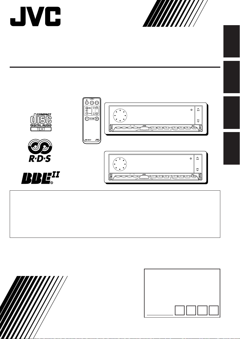
CD RECEIVER
CD-RECEIVER
RECEPTEUR CD
CD-RECEIVER
KD-LX333R
ENGLISH
KD-LX111R
KD-LX333R
SSM
TP/PTY DISPSEL
STDM
BAND
MODE
SOURCE
MONOEQ
ATT
7
8
KD-LX111R
SSM
TP/PTY DISPSEL
STDM
BAND
MODE
SOURCE
MONOEQ
ATT
7
8
This unit is equipped with the display demonstration. To cancel it, see page 8.
Dieses Gerät ist mit einer Demonstrationsfunktion für das Display ausgestattet. Auf
Seite 8 wird beschrieben, wie Sie diese Demonstrationsfunktion deaktivieren können.
Cet appareil est équipé d’une démonstration des affichages. Pour l’annuler, référez-
vous à la page 8.
Dit toestel heeft een display-demonstratiefunctie. Zie bladzijde 8 voor het annuleren
van deze functie.
For installation and connections, refer to the separate manual.
Angaben zu Einbau und Verkabelung entnehmen Sie bitte der gesonderten Anleitung.
Pour l’installation et les raccordements, se référer au manuel séparé.
Zie de afzonderlijke handleiding voor details aangaande het installeren en verbinden van het
toestel.
For Customer Use:
Enter below the password you
INSTRUCTIONS
BEDIENUNGSANLEITUNG
MANUEL D’INSTRUCTIONS
GEBRUIKSAANWIJZING
have entered for your security
lock.
Retain this password for future
reference.
PASSWORD:
9
9
INT RPT RND
10
11
INT RPT RND
10
11
KD-LX333R
OFF
12
KD-LX111R
OFF
12
DEUTSCH
FRANÇAIS
NEDERLANDS
PIM171200
[E/EX]
Page 2
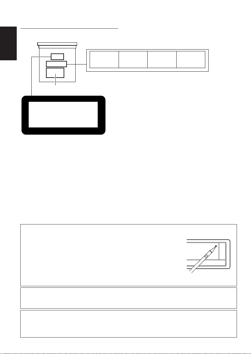
Position And Reproduction Of Labels
Bottom panel of the main unit
ENGLISH
Name/Rating plate
CLASS
LASER
Caution:
This product contains a laser component
of higher laser class than Class 1.
1
PRODUCT
CAUTION: Invisible laser
radiation when open and
interlock failed o r defeated.
AVOID DIRECT EXPOSURE
TO BEAM. (e)
ADVARSEL: Usynlig laserstråling ved åbning, når
sikkerhedsafbrydere er ude
af funktion. Undgåudsættelse for stråling. (d)
VARNING: Osynlig laserstrålning när denna del är
öppnad och spärren är
urkopplad. Betrakta ej
strålen. (s)
VARO : Avattaessa ja
suojalukitus ohitettaessa
olet alttiina näkymättömälle lasersäteilylle.
Älä katso säteeseen. (f)
IMPORTANT FOR LASER PRODUCTS
Precautions:
1.CLASS 1 LASER PRODUCT
2.CAUTION: Invisible laser radiation when open and
interlock failed or defeated. Avoid direct exposure to
beam.
3.CAUTION: Do not open the top cover. There are no
user-serviceable parts inside. Leave all servicing to
qualified service personnel.
4.CAUTION: This CD player uses invisible laser radiation
and is equipped with safety switches to prevent
radiation emission when unloading CDs. It is dangerous
to defeat the safety switches.
5.CAUTION: Use of controls, adjustments or
performance of procedures other than those specified
herein may result in hazardous radiation exposure.
How to reset your unit
Press the reset button on the front panel using a ball-point pen or a
similar tool.
This will reset the built-in microcomputer.
Note:
Your preset adjustments — such as preset channels or sound adjustments —
will also be erased.
Note:
For security reasons, a numbered ID card is provided with this unit, and the same ID number is imprinted on
the unit’s chassis. Keep the card in a safe place, as it will help the authorities to identify your unit if stolen.
CAUTION on Volume Setting
CDs produce very little noise compared with other sources. If the volume level is adjusted for the tuner, for
example, the speakers may be damaged by the sudden incr ease in the output le vel. Ther efor e, lower the volume
before playing a disc and adjust it as required during playback.
2
Page 3

Thank you for purchasing a JVC product. Please read all instructions carefully before operation,
to ensure your complete understanding and to obtain the best possible performance from the unit.
CONTENTS
How to reset your unit............................... 2
LOCATION OF THE BUTTONS............ 4
Control panel ........................................... 4
How to use the number buttons................ 4
Preparing the remote controller................ 5
Remote controller .................................... 6
BASIC OPERATIONS ...................... 7
Turning on the power ................................ 7
Canceling the demonstration.................... 8
Setting the clock ...................................... 8
RADIO BASIC OPERATIONS ............. 9
Listening to the radio ................................ 9
Storing stations in memory....................... 10
Tuning in to a preset station ..................... 11
RDS OPERATIONS ........................ 12
What you can do with RDS....................... 12
Other convenient RDS functions and
adjustments........................................... 16
CD OPERATIONS .......................... 19
Playing a CD............................................ 19
Locating a track or a particular portion
on a CD ................................................. 20
Selecting CD playback modes.................. 20
Prohibiting CD ejection ............................. 21
Playing a CD Text .................................... 21
SOUND ADJUSTMENTS .................. 22
Adjusting the sound ................................. 22
What is BBEII? ......................................... 22
Selecting preset sound modes
(CEQ: custom equalizer)........................ 23
Storing your own sound adjustments ....... 24
OTHER MAIN FUNCTIONS ............... 25
Changing the general settings (PSM) ...... 25
Controlling the volume automatically
(Audio Cruise) (only for KD-LX333R)..... 29
Assigning names to the sources .............. 30
Using the security lock.............................. 32
CD CHANGER OPERATIONS ............. 34
Playing CDs ............................................. 34
Selecting CD playback modes.................. 35
EXTERNAL COMPONENT OPERATIONS ... 37
Playing an external component ................ 37
Using a subwoofer
(only for KD-LX333R)............................. 37
DAB TUNER OPERATIONS ............... 38
Tuning in to an esemble and one of the
services ................................................. 38
Storing DAB services in memory ............. 39
Tuning in to a preset DAB service ............ 40
What you can do more with DAB.............. 41
TROUBLESHOOTING...................... 42
MAINTENANCE ............................ 44
Handling CDs .......................................... 44
SPECIFICATIONS .......................... 45
ENGLISH
BEFORE USE
*
For safety....
• Do not raise the volume level too much, as this will
block outside sounds, making driving dangerous.
• Stop the car before performing any complicated
operations.
*
Temperature inside the car....
If you have parked the car for a long time in hot or
cold weather, wait until the temperature in the car
becomes normal before operating the unit.
3
Page 4
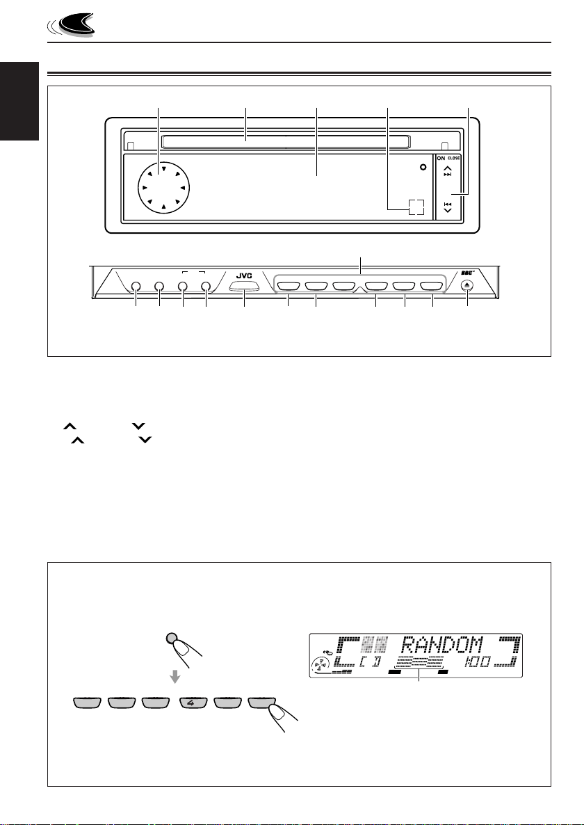
LOCATION OF THE BUTTONS
Control panel
1 2
ENGLISH
SSM
8
BAND
MODE
M
9 p
SEL
TP/PTY DISP
STD
7
6
*When you press OFF 0, the display panel moves down and the CD loading slot appears.
1 Control dial
2 CD loading slot
3 Display panel
4 Remote sensor
5 ¢ / 4 buttons
• ¢ / 4 also functions as ON or
CLOSE button.
6 SEL (S) (select) button
7 TP/PTY (T) (Traffic Programme/Prog r amme
Type) button
8 DISP (D) (display) button
• Also functions as SSM buttons when pressed
together with the BAND MODE (M) button.
SOURCE
3
u
ATT
1
q
8
7
2
w
9
10
3
4
e
MONO
EQ
*The control panel slides out when you press ON CLOSE.
9 BAND MODE (M) button
• Also functions as SSM buttons when pressed
together with the DISP (D) button.
p SOURCE ATT (attenuator) button
q EQ (equalization) button
w MONO (monaural) button
e INT (intro scan) button
r RPT (repeat) button
t RND (random) button
y OFF 0 (eject) button
u Number buttons
5
r
RND RPT INT
12
11
6
t
54
OFF
y
How to use the number buttons:
After pressing BAND MODE (M), the number buttons work as different function buttons (while
“MODE” remains on the display).
EQ
MONO
7
1
2
To use these buttons as number buttons after pressing BAND MODE (M), wait for 5 seconds
without pressing any number button so that “MODE” disappears from the display.
• Pressing BAND MODE (M) again also erases “MODE” from the display.
4
BAND
MODE
M
9
8
35
11
10
DIRECTORY
FILEDISC
TRACK
CEQ
RND RPT INT
12
6
Time countdown indicator
Ex.: When you press button 6 to enter the
RND
RPT
MO
ST
TP
REG
AF
Random function mode.
BBE
PTY
Page 5
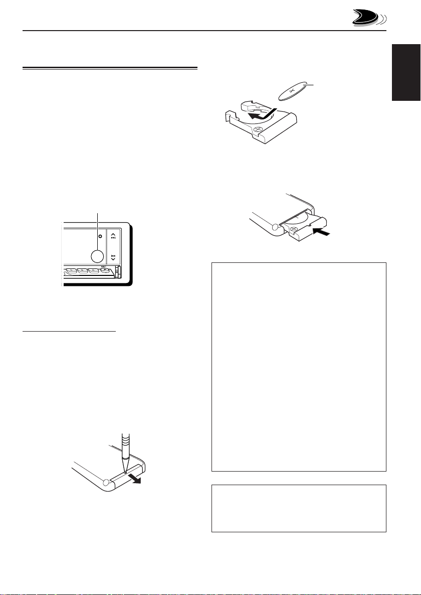
Preparing the remote
controller
This section is only for KD-LX333R.
KD-LX111R can be remotely controlled with an
optionally purchased remote controller. We
recommend that you use remote controller
RM-RK31 or RM-RK50 with your unit.
(Ex.: When you are using RM-RK31.)
Before using the remote controller:
• Aim the remote controller directly at the remote
sensor on the main unit. Make sure there is no
obstacle in between.
Remote sensor
2. Place the battery.
Slide the battery into the holder with the +
side facing upwards so that the battery is
fixed in the holder.
Lithium coin battery
(product number:
CR2025)
3. Return the battery holder.
Insert again the battery holder pushing it until
you hear a clicking sound.
(back side)
ENGLISH
INT RPT RND
10
OFF
12
11
• Do not expose the remote sensor to strong
light (direct sunlight or artificial lighting).
Installing the battery
When the controllable range or effectiveness of
the remote controller decreases, replace the
battery.
1. Remove the battery holder.
1) Push out the battery holder in the direction
indicated by the arrow using a ball-point
pen or a similar tool.
2) Remove the battery holder.
(back side)
1)
2)
WARNING:
• Store the battery in a place where children
cannot reach.
If a child accidentally swallows the battery,
consult a doctor immediately.
• Do not recharge, short, disassemble or heat the
battery or dispose of in a fire.
Doing any of these things may cause the battery
to give off heat, crack or start a fire.
• Do not leave the battery with other metallic
materials.
Doing this may cause the battery to give off heat,
crack or start a fire.
• When throwing away or saving battery, wrap it
in tape and insulate; otherwise, it may cause the
battery to give off heat, crack or start a fire.
• Do not poke the battery with tweezers or similar
tools.
Doing this may cause the battery to give off heat,
crack or start a fire.
CAUTION:
Do not leave the remote controller in a place
(such as dashboards) exposed to direct sunlight
for a long time. Otherwise, it may be damaged.
5
Page 6
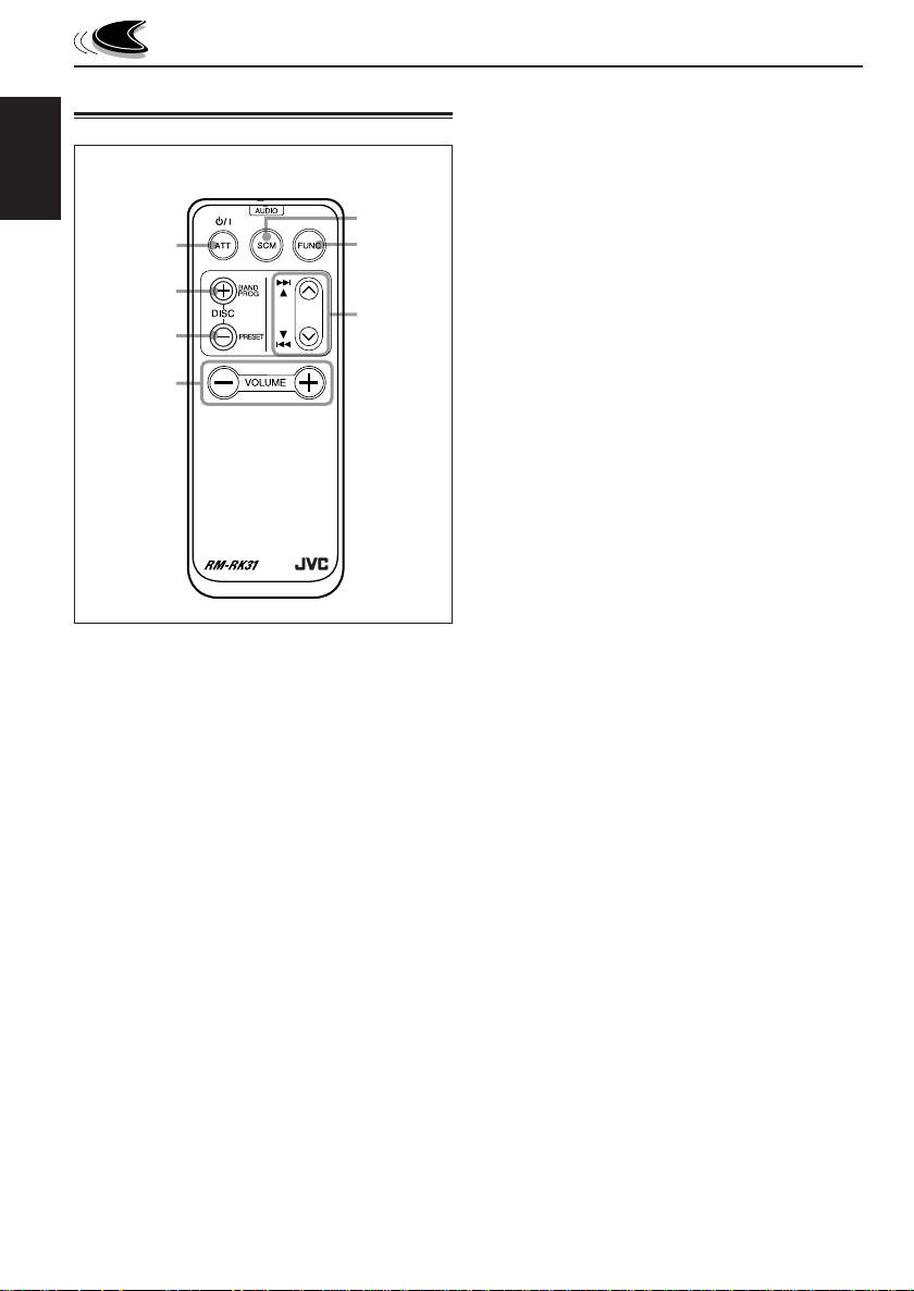
Remote controller
RM-RK31
ENGLISH
1
2
3
4
1 • Turns on the unit if pressed when the unit is
turned off.
• Turns off the unit if pressed and held until
“SEE YOU” appears on the display.
• Drops the volume level if pressed briefly, and
“ATT” rotates on the display.
Press again to resume the volume.
2 • Functions as the BAND button while listening
to an FM broadcast (or the DAB tuner).
Each time you press the button, the band
changes.
• Functions as the DISC + button while
listening to the CD changer.
Each time you press the button, the disc
number increases, and the selected disc
starts playing.
• Does not function as the PROG button.
5
6
7
3 • Functions as the PRESET button while
listening to the radio (or the DAB tuner).
Each time you press the button, the preset
station number increases, and the selected
station is tuned in.
• Functions as the DISC – button while
listening to the CD changer.
Each time you press the button, the disc
number decreases, and the selected disc
starts playing.
4 Functions the same as the control dial on the
main unit.
NOTE:
This button does not function for the
preferred setting mode adjustment.
5 Selects the sound mode.
Each time you press SCM (Sound Control
Memory), the CEQ (custom equalizer) mode
changes.
6 Selects the source.
Each time you press FUNC (function), the
source changes.
7 • Searches stations while listening to the
radio.
• Selects services while listening to the DAB
tuner if pressed briefly.
• Searches ensembles while listening to the
DAB tuner if pressed for more than 1
second.
• Fast-forwards or reverses the track if
pressed and held while listening to a CD.
• Skips to the beginning of the next track or
goes back to the beginning of the current (or
previous) track if pressed briefly while
listening to a CD.
6
Page 7
BASIC OPERATIONS
1
Turning on the power
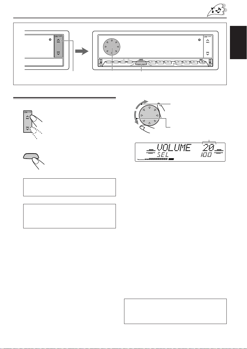
1
Turn on the power.
The display illuminates and the
control panel and control dial
come out.
2
Select the source.
ATT
SOURCE
For KD-LX333R:
= FM = DAB tuner** = CD*
= CD changer** = External component
= AM = (back to the beginning)
For KD-LX111R:
= FM = DAB tuner** = CD*
= CD changer** (or external
component***) = AM
= (back to the beginning)
* If a CD is not in the loading slot, you cannot
** Without connecting the CD changer and/or
***To select the external component, set the
To operate the tuner (FM or AM),
To operate the CD player,
To operate the CD changer,
To operate the external component,
To operate the DAB tuner,
Each time you press the button,
the source changes as follows:
select CD as the source to play.
the DAB tuner, you cannot select it as the
source to play.
“EXT INPUT” setting to “LINE INPUT.”
(See page 28.)
see pages 9 – 11.
see pages 19 – 21.
see pages 34 – 36.
see page 37.
see pages 38 – 41.
SSM
TP/PTY DISPSEL
STDM
3
3
BAND
MODE
SOURCE
MONOEQ
ATT
7
2
Adjust the volume.
INT RPT RND
9
10
8
11
To increase the volume.
To decrease the volume.
Volume level appears.
DIRECTORY
FILEDISC
TRACK
CD
CEQ
RPT
MO
ST
4
Adjust the sound as you want (see
pages 22 – 24).
To drop the volume in a moment
Press SOURCE ATT for more than 1 second
while listening to any source. “ATT” rotates on
the display, and the volume level will drop in a
moment.
To resume the previous volume level, press the
button for more than 1 second again.
To turn off the power
Press and hold OFF 0 until “SEE YOU” appears
on the display.
• If you turn off the power while listening to a
CD, you can start CD playback from where you
have stopped next time you turn on the power.
Note:
When you use this unit for the first time, set the builtin clock correctly, see page 8.
Note on display illustrations:
Illustrations will differ from what appears if
“CLOCK DISP” is set to “CLOCK OFF.” See
page 27.
OFF
ENGLISH
12
RND
PTY
TP
REG
AF
7
Page 8
Canceling the demonstration
Setting the clock
When shipped from the factory, demonstration
has been activated, and starts automatically
when no operations are done for about 20
ENGLISH
seconds.
• It is recommended to cancel the demonstration
before you use the unit for the first time.
To cancel the demonstration, follow the
procedure below.
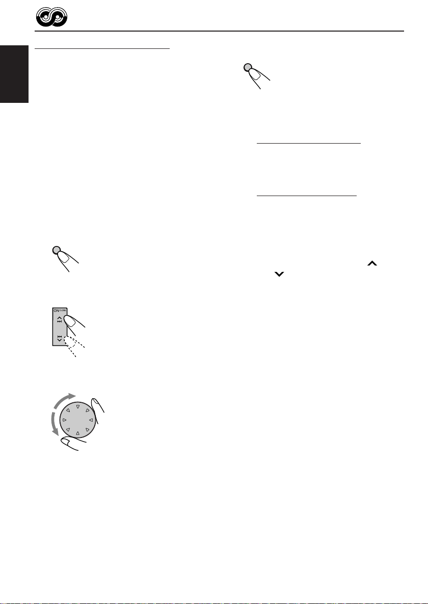
1
Press and hold SEL (S) for more
than 2 seconds so that one of the
PSM items appears on the display.
(See pages 25 and 26.)
SEL
S
2
Select “DEMO MODE” if not shown
on the display.
3
Select “DEMO OFF.”
1
Press and hold SEL (S) for more
than 2 seconds so that one of the
PSM items appears on the display.
(See pages 25 and 26.)
SEL
S
2
Set the hour.
1 Select “CLOCK HOUR” if not shown on
the display.
2 Adjust the hour.
1
3
Set the minute.
1 Select “CLOCK MIN (minute).”
2 Adjust the minute.
1
2
2
4
Finish the setting.
SEL
S
To activate the demonstration again, repeat
the same procedure and select “DEMO ON” in
step 3.
8
4
Set the clock system.
1 Select “24H/12H.”
2 Adjust “24HOUR” or “12HOUR.”
1
5
Finish the setting.
SEL
S
To check the current clock time with “CLOCK
DISP” set to “CLOCK OFF,” press DISP (D).
The clock time is shown for 5 seconds.
2
Page 9
RADIO BASIC OPERATIONS
SSM
BAND
MODE
TP/PTY DISPSEL
STDM
SSM
TP/PTY DISP
SEL
ST
D
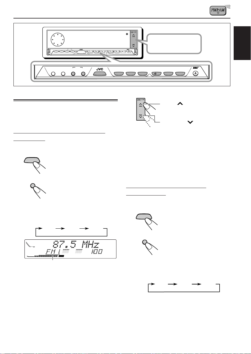
Listening to the radio
You can use either automatic searching or
manual searching to tune in to a particular
station.
Searching a station automatically:
Auto search
1
Select the band.
ATT
SOURCE
BAND
MODE
M
Each time you press and hold the button,
the FM band changes as follows:
DIRECTORY
FILEDISC
TRACK
CD
Selected band appears.
Note:
This receiver has three FM bands (FM1, FM2,
FM3). You can use any one of them to listen to
an FM broadcast.
1 Press SOURCE ATT to
select FM or AM as the
source.
2 If necessary, press and
hold BAND MODE (M) to
select the FM band
number (FM1, FM2 or
FM3).
FM1 FM2 FM3
CEQ
RPT
MO
ST
SOURCE
BAND
MODE
RND
MONOEQ
ATT
7
8
SOURCE
M
PTY
TP
REG
AF
9
ATT
Press ON CLOSE to
INT RPT RND
10
1
OFF
12
11
MONO
EQ
8
7
2
2
turn on the power.
9
3
11
10
5
Start searching a station.
Press ¢ to search
stations of higher frequencies.
Press 4 to search
stations of lower frequencies.
When a station is received, searching
stops.
To stop searching before a station is
received, press the same button you have
pressed for searching.
Searching a station manually:
Manual search
1
Select the band.
ATT
SOURCE
BAND
MODE
M
Each time you press and hold the button,
the FM band changes as follows:
Note:
This receiver has three FM bands (FM1, FM2,
FM3). You can use any one of them to listen to
an FM broadcast.
1 Press SOURCE ATT to
select FM or AM as the
source.
2 If necessary, press and
hold BAND MODE (M) to
select the FM band
number (FM1, FM2 or
FM3).
FM1 FM2 FM3
ENGLISH
RND RPT INT
6
OFF
12
CONTINUED ON THE NEXT PAGE
9
Page 10
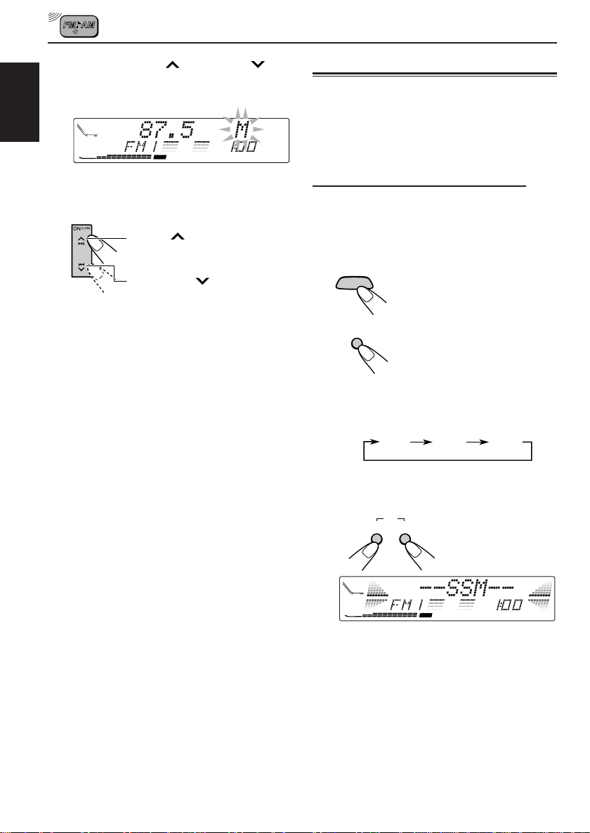
2
Press and hold ¢ or 4
until “M (manual)” starts flashing on
the display.
DIRECTORY
ENGLISH
FILEDISC
TRACK
CD
CEQ
RPT
MO
ST
3
Tune in to a station you want while
“M” is flashing.
Press ¢ to tune in to
stations of higher frequencies.
Press 4 to tune in to
stations of lower frequencies.
Storing stations in memory
You can use one of the following two methods to
store broadcasting stations in memory.
• Automatic preset of FM stations: SSM (Strongstation Sequential Memory)
RND
PTY
TP
REG
AF
• Manual preset of both FM and AM stations
FM station automatic preset: SSM
You can preset 6 local FM stations in each FM
band (FM1, FM2 and FM3).
1
Select the FM band (FM1 – 3) you
want to store FM stations into.
ATT
SOURCE
1 Press SOURCE ATT to
select FM as the source.
• If you release your finger from the button,
the manual mode will automatically turn off
after 5 seconds.
• If you hold down the button, the frequency
keeps changing (50 kHz intervals for FM
and 9 kHz intervals for AM – MW/LW) until
you release the button.
When an FM stereo broadcast is hard to
receive:
1 Press BAND MODE (M) while listening to an
FM stereo broadcast (the ST indicator lights up
while receiving an FM stereo broadcast).
“MODE” appears on the display, and the
number buttons can work as different function
buttons.
2 Press MONO, while “MODE” is still on the
display, so that the MO indicator lights up on
the display.
The sound you hear becomes monaural but
the reception will be improved (the ST indicator
goes off).
Each time you press the button, the MO
indicator lights up and goes off alternately.
BAND
MODE
M
2 If necessary, press and
hold BAND MODE (M) to
select the FM band
number (FM1, FM2 or
FM3).
Each time you press and hold the button,
the FM band changes as follows:
FM1 FM2 FM3
2
Press and hold both buttons for
more than 2 seconds.
SSM
BAND
DISP
MODE
DM
DIRECTORY
FILEDISC
TRACK
CD
CEQ
“SSM” appears, then disappears when automatic
preset is over.
Local FM stations with the strongest signals are
searched and stored automatically in the band
number you have selected (FM1, FM2 or FM3).
These stations are preset in the number buttons
— No.1 (lowest frequency) to No.6 (highest
frequency).
When automatic preset is over, the station stored
in number button 1 will be automatically tuned in.
RND
RPT
MO
ST
TP
REG
AF
10
Page 11
Manual preset
You can preset up to 6 stations in each band
(FM1, FM2, FM3 and AM) manually.
Ex.: Storing an FM station of 88.3 MHz into the
preset number 1 of the FM1 band
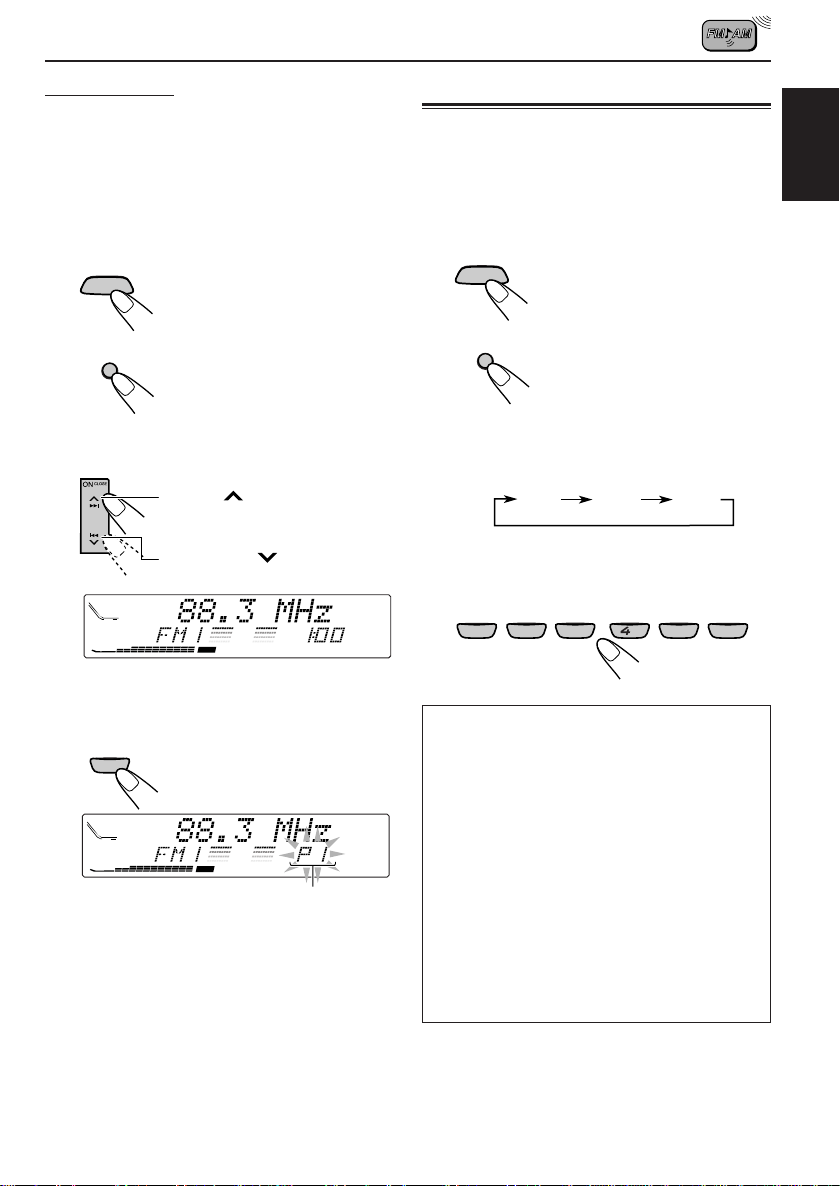
1
Select the band (in this example,
FM1).
ATT
SOURCE
1 Press SOURCE ATT to
select FM as the source.
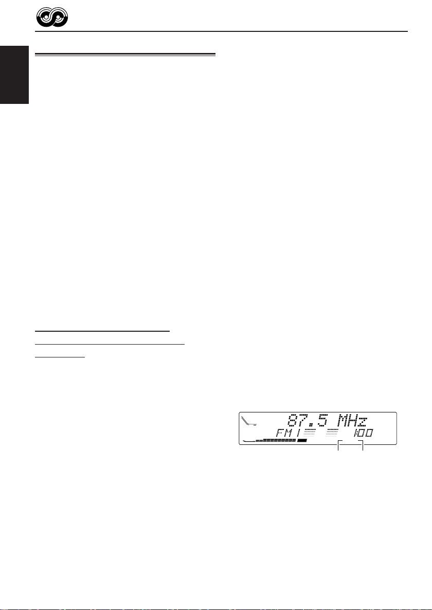
Tuning in to a preset station
You can easily tune in to a preset station.
Remember that you must store stations first. If
you have not stored them y et, see “Storing
stations in memory” on pages 10 and 11.
1
Select the band.
ATT
SOURCE
1 Press SOURCE ATT to
select FM or AM as the
source.
ENGLISH
BAND
MODE
M
2 Press and hold BAND
MODE (M) repeatedly to
select the FM1 band.
2
Tune in to a station (in this example,
of 88.3 MHz).
Press ¢ to tune in to
stations of higher frequencies.
Press 4 to tune in to
stations of lower frequencies.
DIRECTORY
FILEDISC
TRACK
CD
CEQ
3
Press and hold the number button
RND
RPT
MO
ST
AF
REG
BBE
PTY
TP
(in this example, 1) for more than 2
seconds.
EQ
7
1
DIRECTORY
FILEDISC
TRACK
CD
CEQ
RND
RPT
MO
ST
PTY
TP
REG
AF
“PI” flashes for a few seconds.
4
Repeat the above procedure to store
other stations into other preset
numbers.
Notes:
• A previously preset station is erased when a new
station is stored in the same preset number.
• Preset stations are erased when the power supply to
the memory circuit is interrupted (for example,
during battery replacement). If this occurs, preset
the stations again.
BAND
MODE
M
2 If necessary, press and
hold BAND MODE (M) to
select the FM band
number (FM1, FM2 or
FM3).
Each time you press and hold the button,
the FM band changes as follows:
FM1 FM2 FM3
2
Select the number (1 – 6) for the
preset station you want.
EQ
MONO
7
1
2
If the sound quality decreases and the
stereo effect is lost while listening to an
FM station
In some areas, adjacent stations may
interfere with each other. If this interference
occurs, this unit can automatically reduce
this interference noise (the initial setting
when shipped from the factory). However, in
this case, the sound quality will be degraded
and the stereo effect will be also lost.
If you do not want to degrade the sound
quality and to lose the stereo effect, rather
than to eliminate the interference noise, see
“To change the FM tuner selectivity — IF
FILTER” on page 28.
9
8
35
11
10
RND RPT INT
12
6
11
Page 12
RDS OPERATIONS
What you can do with RDS
RDS (Radio Data System) allows FM stations to
send an additional signal along with their regular
programme signals. For example, the stations
ENGLISH
send their station names, as well as information
about what type of programme they broadcast,
such as sports or music, etc.
Another advantage of RDS function is called
“Enhanced Other Networks.” By using the
Enhanced Other Networks data sent from a
station, you can tune in to a different station of a
different network broadcasting your favourite
programme or traffic announcement while
listening to another programme or to another
source such as CD.
By receiving the RDS data, this unit can do the
following:
• Tracing the same programme automatically
(Network-Tracking Reception)
• Standby Reception of TA (Traffic
Announcement) or your favourite programme
• PTY (Programme Type) search
• Programme search
• And some other functions
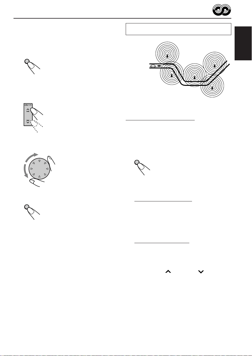
Tracing the same programme
automatically (Network-Tracking
Reception)
When driving in an area where FM reception is
not good, the tuner built in this unit automatically
tunes in to another RDS station, broadcasting the
same programme with stronger signals. So, you
can continue to listen to the same programme in
its finest reception, no matter where you drive.
(See the illustration on the next page.)
Two types of the RDS data are used to make
Network-Tracking Reception work correctly — PI
(Programme Identification) and AF (Alternative
Frequency).
Without receiving these data correctly from the
RDS station you are listening to, NetworkTracking Reception will not operate.
To use Network-Tracking Reception
You can select the different modes of networktracking reception to continue listening to the
same programme in its finest reception.
When shipped from the factory, “AF” is selected.
• AF: Network-Tracking Reception is
activated with Regionalization set to
“off.”
With this setting, the unit switches to
another station within the same
network when the receiving signals
from the current station become
weak. (In this mode, the programme
may differ from the one currently
received.)
The AF indicator lights up but the
REG indicator does not.
• AF REG: Network-Tracking Reception is
• OFF: Network-Tracking Reception is
activated with Regionalization set to
“on.”
With this setting, the unit switches to
another station, within the same
network, broadcasting the same
programme when the receiving
signals from the current station
become weak.
Both the AF indicator and the REG
indicator light up.
deactivated.
Neither the AF indicator nor the REG
indicator lights up.
DIRECTORY
FILEDISC
TRACK
CD
CEQ
RND
RPT
MO
ST
AF
AF indicator REG indicator
REG
PTY
TP
12
Page 13
1
Press and hold SEL (S) for more
than 2 seconds so that one of the
PSM items appears on the display.
(See pages 25 and 26.)
SEL
S
2
Select “AF–REG (Alternative
frequency/Regionalization reception)”
if not shown on the display .
3
Select the desired mode – “AF,”
“AF REG” or “OFF.”
4
Finish the setting.
SEL
S
Note:
If a DAB tuner is connected and Alternative Reception
(for DAB services) is activated, Network-Tracking
Reception is also activated automatically. On the
other hand, Network-Tracking Reception cannot be
deactivated without deactivating Alternative
Reception. (See page 41.)
The same programme can be received on
different frequencies.
Programme 1
broadcasting
on frequency A
Programme 1
broadcasting
on frequency B
Programme 1
broadcasting
on frequency C
Programme 1
broadcasting
on frequency E
Programme 1
broadcasting
on frequency D
Using TA Standby Reception
TA Standby Reception allows the unit to s witch
temporarily to Traffic Announcement (TA) from
the current source (another FM station or CD and
other connected components.)
• TA Standby Reception will not work if you are
listening to an AM station.
TP/PTY
T
Press TP/PTY (T) to activate TA Standby Reception.
7 When the current source is FM, the TP
indicator either lights up or flashes.
• If the TP indicator lights up, TA Standby
Reception is activated.
If a station starts broadcasting a traffic
announcement, “TRAFFIC” appears on the
display, and this unit automatically tunes in to
the station. The volume changes to the
preset TA volume level (see page 17) and the
traffic announcement can be heard.
• If the TP indicator flashes, TA Standby
Reception is not yet activated since the
station being received does not provide the
signals used for TA Standby Reception.
To activate TA Standby Reception, you need
to tune in to another station providing these
signals. Press ¢ or 4 to search
for such a station.
When a station providing these signals is
tuned in, the TP indicator stops flashing and
remains lit. Now TA Standby Reception is
activated.
7 When the current source is other than FM,
the TP indicator lights up.
If a station starts broadcasting a traffic
announcement, “TRAFFIC” appears on the
display, and this unit automatically changes the
source and tunes in to the station.
To deactivate the TA Standby Reception, press
TP/PTY (T) again.
ENGLISH
13
Page 14
Using PTY Standby Reception
PTY Standby Reception allows the unit to switch
temporarily to your favourite programme (PTY:
Programme Type) from the current source
(another FM station or CD).
ENGLISH
• PTY Standby Reception will not work if you are
listening to an AM station.
You can select your favourite programme type for
PTY Standby Reception.
When shipped from the factory, PTY Standby
Reception is turned off. (“OFF” is selected for
PTY Standby Reception.)
1
Press and hold SEL (S) for more
than 2 seconds so that one of the
PSM items appears on the display.
(See pages 25 and 26.)
SEL
S
2
Select “PTY STBY (standby)” if not
shown on the display.
3
Select one of the twenty-nine PTY
codes. (See page 18.)
Selected code name
appears on the display and
is stored into memory.
• To cancel the PTY
Standby Reception,
select “OFF.”
4
Finish the setting.
SEL
S
7 When the current source is FM, the PTY
indicator either lights up or flashes.
• If the PTY indicator lights up, PTY
Standby Reception is activated.
If a station starts broadcasting the
selected PTY programme, this unit
automatically tunes in to the station.
• If the PTY indicator flashes, PTY
Standby Reception is not yet activated
since the station being received does
not provide the signals used for PTY
Standby Reception.
To activate PTY Standby Reception, you
need to tune in to another station
providing these signals. Press ¢ or
4 to search for such a station.
When a station providing these signals
is tuned in, the PTY indicator stops
flashing and remains lit. Now PTY
Standby Reception is activated.
7 When the current source is other than
FM, the PTY indicator lights up.
If a station starts broadcasting the
selected PTY programme, this unit
automatically changes the source and
tunes in to the station.
To deactivate the PTY standby mode, select
“OFF” in step 3 of the procedure on the left
column. The PTY indicator disappears.
14
Page 15
Searching your favorite programme
You can search any one of the PTY codes.
In addition, you can store your 6 favorite
programme types in the number buttons.
When shipped from the factory, the following 6
programme types have been stored in the
number buttons (1 to 6).
To store your favorite programme types, see
below.
To search your favorite programme type, see
page 16.
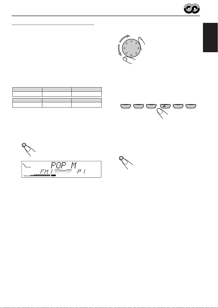
1
POP M
2
ROCK M EASY M
45
CLASSICS
AFFAIRS
To store your favorite programme types
1
Press and hold TP/PTY (T) for more
than 2 seconds.
TP/PTY
T
3
6
VARIED
2
Select one of the twenty-nine PTY
codes. (See page 18.)
Selected code name
appears on the display.
3
Press and hold the number button
for more than 2 seconds to store the
PTY code selected into the preset
number you want.
EQ
MONO
7
1
2
9
8
35
10
Preset number flashes for a few seconds.
4
Press and hold TP/PTY (T) for more
than 2 seconds.
TP/PTY
T
ENGLISH
RND RPT INT
12
11
6
CEQ
RND
RPT
MO
ST
TP
REG
AF
The last selected PTY code appears.
15
Page 16
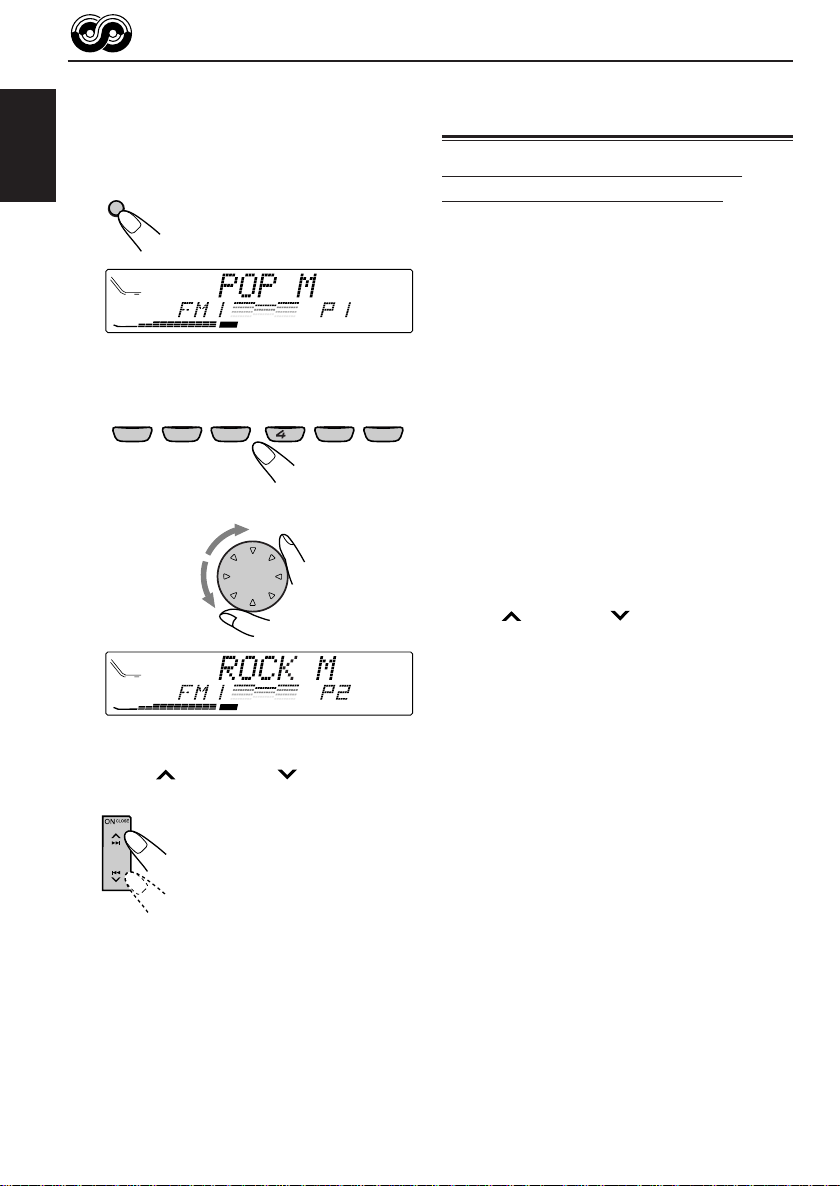
To search your favorite programme type
1
Press and hold TP/PTY (T) for more
than 2 seconds while listening to an
FM station.
ENGLISH
TP/PTY
T
CEQ
The last selected PTY code appears.
2
Select one of the PTY codes.
EQ
MONO
8
7
1
35
2
CEQ
Ex.:When “ROCK M” is selected.
3
Press ¢ or 4 to start PTY
search for your favorite programme.
RND
RPT
MO
ST
9
REG
AF
10
OR
RND
RPT
MO
ST
REG
AF
Other convenient RDS
functions and adjustments
Automatic selection of the station
when using the number buttons
Usually when you press the number button, the
preset station is tuned in.
However, when the preset station is an RDS
station, something different will happen. If the
TP
RND RPT INT
11
6
PTY
TP
signals from that preset station are not sufficient
for good reception, this unit, using the AF data,
tunes in to another frequency broadcasting the
same programme as the original preset station is
broadcasting. (Programme search)
• The unit takes some time to tune in to another
12
station using Programme search.
To activate programme search, follow the
procedure below.
• See also “Changing the general settings
(PSM)” on page 25.
1 Press and hold SEL (S) for more than 2
seconds so that one of the PSM items appears
on the display.
2 Press ¢ or 4 to select
“P(Programme)-SEARCH.”
3 Turn the control dial to select “SEARCH ON.”
Now programme search is activated.
4 Press SEL (S) to finish the setting.
To cancel programme search, repeat the same
procedure and select “SEARCH OFF” in step 3.
• If there is a station broadcasting a programme
of the same PTY code as you selected, that
station is tuned in.
• If there is no station broadcasting a programme
of the same PTY code as you selected, the
station will not change.
Note:
In some areas, the PTY search will not work correctly.
16
Page 17

Changing the display mode while
listening to an FM station
You can change the initial indication on the
display to either station name (PS NAME) or to
station frequency (FREQUENCY), while listening
to an FM RDS station.
• See also “Changing the general settings
(PSM)” on page 25.
1 Press and hold SEL (S) for more than 2
seconds so that one of the PSM items appears
on the display.
2 Press ¢ or 4 to select “TUNER
DISP (display).”
3 Turn the control dial to set to the desired
indication (“PS NAME” or “FREQUENCY”).
4 Press SEL (S) to finish the setting.
Setting the TA volume level
You can preset the volume level for TA Standby
Reception. When a traffic programme is received,
the volume level automatically changes to the
preset level.
• See also “Changing the general settings
(PSM)” on page 25.
1 Press and hold SEL (S) for more than 2
seconds so that one of the PSM items appears
on the display.
2 Press ¢ or 4 to select “TA VOL
(volume).”
3 Turn the control dial to set to the desired
volume.
You can set it from “TA VOL 00” to “TA VOL 50.”
4 Press SEL (S) to finish the setting.
ENGLISH
Note:
By pressing DISP (D), you can change the display
while listening to an FM RDS station.
Each time you press the button, the following
information appears on the display:
Station name
(PS NAME)
Station frequency
(FREQUENCY)
Programme type
(PTY)
• Then, the display goes back to the original
indication in several seconds.
Automatic clock adjustment
When shipped from the factory, the clock built in
this unit is set to be readjusted automatically
using the CT (Clock Time) data in the RDS
signal.
If you do not want to use automatic clock
adjustment, follow the procedure below.
• See also “Changing the general settings
(PSM)” on page 25.
1 Press and hold SEL (S) for more than 2
seconds so that one of the PSM items appears
on the display.
2 Press ¢ or 4 to select “AUTO ADJ
(adjustment).”
3 Turn the control dial to select “ADJUST OFF.”
Now automatic clock adjustment is canceled.
4 Press SEL (S) to finish the setting.
To reactivate clock adjustment, repeat the same
procedure and select “ADJUST ON” in step 3.
Note:
You must stay tuned to the same station for more than
2 minutes after setting “AUTO ADJ” to “ADJUST
ON.” Otherwise, the clock time will not be adjusted.
(This is because the unit takes up to 2 minutes to
capture the CT data in the RDS signal.)
17
Page 18

PTY codes
NEWS: News
AFFAIRS: Topical programmes expanding
ENGLISH
INFO: Programmes which impart
SPORT: Sport events
EDUCATE: Educational programmes
DRAMA: Radio plays
CULTURE: Programmes on national or
SCIENCE: Programmes on natural science
VARIED: Other programmes like
POP M: Pop music
ROCK M: Rock music
EASY M: Easy-listening music
LIGHT M: Light music
CLASSICS: Classical music
OTHER M: Other music
WEATHER: Weather information
FINANCE: Reports on commerce, trading,
on current news or affairs
advice on a wide variety of
topics
regional culture
and technology
comedies or ceremonies
the Stock Market, etc.
CHILDREN: Entertainment programmes for
children
SOCIAL: Programmes on social activities
RELIGION: Programmes dealing with any
aspect of belief or faith, or the
nature of existence or ethics
PHONE IN: Programmes where people can
express their views either by
phone or in a public forum
TRAVEL: Programmes about travel
destinations, package tours,
and travel ideas and
opportunities
LEISURE: Programmes concerned with
recreational activities such as
gardening, cooking, fishing, etc.
JAZZ: Jazz music
COUNTRY: Country music
NATION M: Current popular music from
another nation or region, in that
country’s language
OLDIES: Classic pop music
FOLK M: Folk music
DOCUMENT: Programmes dealing with
factual matters, presented in an
investigative style
18
Page 19

SSM
BAND
MODE
TP/PTY DISPSEL
STDM
TP/PTY DISP
SEL
STD
CD OPERATIONS
Press ON CLOSE to
ATT
SOURCE
SSM
BAND
MODE
M
9
8
SOURCE
10
ATT
7
INT RPT RND
MONOEQ
OFF
12
11
MONO
EQ
8
7
1
2
turn on the power.
9
10
3
ENGLISH
RND RPT INT
11
6
5
OFF
12
Playing a CD
1
Open the loading slot.
OFF
The display panel moves down, and the
loading slot appears.
2
Insert a disc into the loading slot.
The unit draws in a
CD, the display panel
moves up, and CD
play starts
automatically.
DIRECTORY
FILEDISC
TRACK
CD
The CD-in indicator
lights up.
Total track number of
the inserted disc
DIRECTORY
FILEDISC
TRACK
CD
Current track
DIRECTORY
FILEDISC
TRACK
CD
CEQ
CEQ
CEQ
RND
RPT
MO
ST
Total playing time of
the inserted disc
RND
RPT
MO
ST
Elapsed playing time
RND
RPT
MO
ST
Notes:
• When a CD is in the loading slot, selecting “CD”
as the source by pressing SOURCE ATT to starts
CD play.
• When a CD is inserted upside down, the CD
automatically ejects.
• When you play a CD Text, the disc title and
performer appear on the display. Then the current
track title appears on the display, followed by the
track number and elapsed playing time. See also
“Playing a CD Text” (page 21) and “To select the
scroll mode — SCROLL” (page 27).
If a CD Text includes much text information, some
may not appear on the display.
• If you change the source, CD play also stops
(without ejecting the CD).
Next time you select “CD” as the source, CD play
will start from where you have stopped.
To stop play and eject the CD
Press OFF 0 briefly.
CD play stops, the display panel moves down,
then the CD automatically ejects from the loading
PTY
TP
REG
AF
PTY
TP
REG
AF
TP
REG
AF
slot.
To move up the display panel, press ¢ or
4 . If no button is pressed, the display
panel will move up in about 5 minutes.
CAUTION: NEVER insert your finger between
the display panel and the unit, as it
may get caught in the unit.
Note:
If the ejected disc is not removed for about 15
seconds, the disc is automatically inserted again into
the loading slot to protect it from dust. (CD play will
not start this time.)
19
Page 20

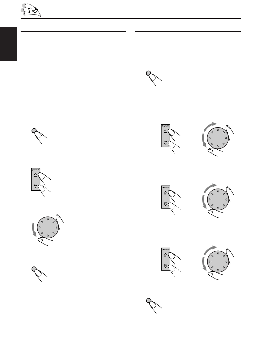
Locating a track or a
particular portion on a CD
To fast-forward or reverse the track
ENGLISH
Press and hold ¢, while
playing a CD, to fast-forward the
track.
Press and hold4 , while
playing a CD, to reverse the track.
To go to the next tracks or the previous
tracks
Press ¢ briefly, while playing
a CD, to go ahead to the beginning
of the next track. Each time you
press the button consecutively, the
beginning of the next tracks is
located and played back.
Press 4 briefly, while playing
a CD, to go back to the beginning
of the current track. Each time you
press the button consecutively, the
beginning of the previous tracks is
located and played back.
To go to a particular track directly
EQ
MONO
7
1
2
Press the number button corresponding to the
track number to start its playback.
• To select a track number from 1 – 6:
Press 1 (7) – 6 (12) briefly.
• To select a track number from 7 – 12:
Press and hold 1 (7) – 6 (12) for more than 1
second.
9
8
35
11
10
Selecting CD playback modes
To play back tracks at random (Random
Play)
You can pla y bac k all tr acks on the CD at random.
BAND
MODE
M
RND
12
6
DIRECTORY
FILEDISC
TRACK
When the random mode is turned on, the RND
indicator lights up on the display and a track
randomly selected starts playing.
To play back tracks repeatedly (Repeat
Play)
You can play back the current track repeatedly.
BAND
MODE
RND RPT INT
12
6
M
RPT
11
5
Track number of the currently playing track
DIRECTORY
FILEDISC
TRACK
1 Press BAND MODE (M) while
playing a CD. “MODE”
appears on the display, and
the number buttons can work
as different function buttons.
2 Press RND (random), while
“MODE” is still on the display,
so that the RND indicator
lights up on the display.
Each time you press the
button, CD random play mode
turns on and off alternately.
CEQ
RND
RPT
MO
ST
RND indicator
PTY
TP
REG
AF
1 Press BAND MODE (M) while
playing a CD. “MODE”
appears on the display, and
the number buttons can work
as different function buttons.
2 Press RPT (repeat), while
“MODE” is still on the display,
so that the RPT indicator
lights up on the display.
Each time you press the
button, CD repeat play mode
turns on and off alternately.
20
CEQ
RND
RPT
MO
ST
TP
REG
AF
RPT indicator
When the repeat mode is turned on, the RPT
indicator lights up on the display.
Page 21

To play back only intros (Intro Scan)
You can play back the first 15 seconds of each
track sequentially.
BAND
MODE
M
INT
10
Track number of the currently playing track
1 Press BAND MODE (M) while
playing a CD. “MODE”
appears on the display, and
the number buttons can work
as different function buttons.
2 Press INT (intro scan), while
“MODE” is still on the display.
Each time you press the
button, CD intro scan mode
turns on and off alternately.
Playing a CD Text
In a CD Text, some information about the disc (its
disc title, performer and track title) is recorded.
You can show these disc information on the
display.
Select text display mode while playing a
CD Text.
DISP
D
Each time you press the button, the display
changes as follows:
ENGLISH
CEQ
RND
RPT
MO
ST
REG
AF
When the intro scan mode is turned on, “INTRO”
appears on the display for 5 seconds and the
track number flashes.
Prohibiting CD ejection
You can prohibit CD ejection and can lock a CD
in the loading slot.
While pressing SOURCE ATT, press and hold
OFF 0 for more than 2 seconds. “NO EJECT”
flashes on the display for about 5 seconds, and
the CD is locked and cannot be ejected.
DIRECTORY
TRACK
CEQ
RND
RPT
MO
ST
AF
Note:
If you press OFF 0 while CD ejection is prohibited,
the control panel moves down, but the CD cannot be
ejected. (“NO EJECT” appears on the display.)
To move up the display panel, press ¢ or
4 .
To cancel the prohibition and unlock the CD,
press and hold OFF 0 for more than 2 seconds
again, while pressing SOURCE ATT. “EJECT
OK” flashes on the display for about 5 seconds,
and the CD is unlocked.
REG
BBE
PTY
TP
Disc Title / Performer
(The DISC indicator lights up)
Track Title
(The TRACK indicator lights up)
Current track no. and
Elapsed playing time
Notes:
• The display shows up to 10 characters at one time
and scrolls if there are more than 10 characters.
See also “To select the scroll mode — SCROLL”
on page 27.
• When you press DISP (D) while playing a
conventional CD, “NO NAME” appears for the
disc title/performer and the track title.
21
Page 22

SOUND ADJUSTMENTS
R
Adjusting the sound
You can adjust the sound characteristics to your
preference.
ENGLISH
1
Select the item you want to adjust.
SEL
S
Indication To do: Range
BASS Adjust the bass. –06 (min.)
TRE Adjust the treble. –06 (min.)
FAD* Adjust the front R06 (Rear only)
BAL Adjust the left L06 (Left only)
BBE See “What is BBE 1, BBE 2,
WOOFER Adjust the 00 (min.)
(only for subwoofer output |
KD-LX333R) level. 08 (max.)
VOLUME Adjust the volume. 00 (min.)
* If you are using a two-speaker system, set the fader
level to “00.”
2
Adjust the level.
Each time you press the button,
the adjustable items change as
follows:
BASS
(bass)
VOLUME
(volume)
TRE
(treble)
(only for KD-LX333R)
FAD
(fader)
WOOFER
|
+06 (max.)
|
+06 (max.)
and rear speaker |
balance. F06 (Front only)
and right speaker |
balance. R06 (Right only)
BBEII?” on the right BBE 3,
column. BBE OFF
|
50 (max.)
To increase the level.
BAL
(balance)
BBE
Note:
Normally the control dial works for volume
adjustment. So you do not have to select “VOLUME”
to adjust the volume level.
What is BBEII?
The BBEII* function restores the brilliance and
clarity of the original live sound in recording,
broadcasts, etc.
When a speaker reproduces sound, it introduces
frequency-dependent phase shifting, causing
high-frequency sounds to take longer to reach
the ear than low frequency sounds. The BBE
function adjusts the phase relationship between
the low, mid and high frequencies by adding a
progressively longer delay time to the low and
mid frequencies, so that all frequencies reach the
listener’s ears at the proper time.
In addition, the BBEII function boosts low and
high frequencies, which loudspeakers tend to be
less efficient in reproducing, through dynamic,
program-driven augmentation. When combined
with the phase compensation feature, the
resulting sound has a clearer, more finely
detailed “live” presence.
As you turn the control dial, the BBEII function
changes as follows:
BBE 1 BBE 2
BBE 3
BBE OFF
(Canceled)
DIRECTORY
FILEDISC
TRACK
CEQ
As the number gets higher, the BBEII function
becomes stronger.
When shipped from the factory, the BBE
function is set to “BBE OFF.”
RND
RPT
MO
ST
REG
AF
II
BBE
PTY
TP
II
22
To decrease the level.
DIRECTORY
CEQ
Equalization pattern changes as you
adjust the bass or treble.
RND
RPT
MO
ST
* Under license from BBE Sound, Inc.
is a trademark of BBE Sound, Inc.
BBE
PTY
TP
REG
AF
Page 23

Selecting preset sound modes
(CEQ: custom equalizer)
You can select a preset sound mode (CEQ:
custom equalizer) suitable to the music genre.
1
Press BAND MODE (M) to make the
number buttons work as different
function buttons.
BAND
MODE
M
2
Activate custom equalizer (CEQ).
EQ
1
The last selected sound mode is
7
recalled and applied to the
current sound.
Indication For: Preset values
BASS TRE BBE
II
USER (Flat sound) 00 00 BBE OFF
ROCK Rock or +03 +01 BBE 2
disco music
CLASSIC Classical +01 –02 BBE OFF
music
POPS Light music +04 +01 BBE OFF
HIP HOP Funk or Rap +02 00 BBE 2
music
JAZZ Jazz music +02 +03 BBE OFF
Notes:
• You can adjust each sound mode to your preference,
and store it in memory.
If you want to adjust and store your original sound
mode, see “Storing your own sound adjustments”
on page 24.
• To adjust the bass and treble reinforcement levels or
to turn on/off the BBEII function temporarily, see
page 22.
ENGLISH
CEQ
Ex.: If you have selected “USER” previously.
3
Select the sound mode you want.
EQ
1
Each time you press the button,
7
the sound modes changes as
RND
RPT
MO
ST
follows:
USER
Ex.: If you select “ROCK.”
ROCK
CEQ
RND
RPT
MO
ST
PTY
TP
REG
AF
CLASSIC
POPSHIP HOPJAZZ
PTY
TP
REG
AF
BBE
To store a sound mode separately for
each playback source (CEQ Link)
You can select a sound mode and store it in
memory. It will be recalled every time you select
the same source and will be shown on the
display.
A sound mode can be stored for each of the
following sources — FM1, FM2, FM3, AM, CD
and external components.
• See also “Changing the general settings
(PSM)” on page 25.
1 Press and hold SEL (S) for more than 2
BBE
seconds so that one of the PSM items appears
on the display.
2 Press ¢ or 4 to select “CEQ LINK”
(Custom Equalization Link).
3 Turn the control dial to select “LINK ON.”
4 Press SEL (S) to finish the setting.
To cancel CEQ Link, repeat the same
procedure and select “LINK OFF” in step 3.
Note:
When you change the “CEQ LINK” setting, sound
mode (CEQ) is automatically reset to “USER.”
23
Page 24

• When “CEQ LINK” is set to “LINK ON”
The selected sound mode can be stored in
memory for the current source.
Each time you change to the same source, the
same sound mode is also recalled and shown
ENGLISH
on the display. The CEQ indicator also flashes.
• When “CEQ LINK” is set to “LINK OFF”
The selected sound mode effect applies to any
source.
4
Select the items you want to adjust.
SEL
5
Adjust the level.
• See page 22 for details.
S
To increase the level.
Storing your own sound
adjustments
You can adjust the sound modes to your
preference and store your own adjustments in
memory.
• There is a time limit in doing the following
procedure. If the setting is canceled before you
finish, start from step 1 again.
1
Press BAND MODE (M) to make the
number buttons work as different
function buttons.
BAND
MODE
M
2
Activate custom equalizer (CEQ).
EQ
1
Ex.: If you have selected “POPS” previously.
The last selected sound mode is
7
recalled and applied to the
current sound.
CEQ
RPT
MO
ST
REG
BBE
PTY
TP
RND
AF
To decrease the level.
DIRECTORY
CEQ
Equalization pattern changes as you
adjust the bass or treble.
Ex.: When you adjust “TRE (treble).”
6
Repeat steps 4 and 5 to adjust the
RND
RPT
MO
ST
AF
REG
BBE
PTY
TP
other items.
• To adjust the BBEII level, see page 22.
7
Repeat the same procedure to store
other sound modes.
To reset to the factory settings, repeat the
same procedure and reassign the preset values
listed in the table on page 23.
24
3
Select the sound mode you want.
EQ
1
Each time you press the button,
7
the sound modes changes as
follows:
USER
ROCK
CLASSIC
POPSHIP HOPJAZZ
Page 25

OTHER MAIN FUNCTIONS
Changing the general settings
(PSM)
You can change the items listed on the next page
by using the PSM (Preferred Setting Mode)
control.
Basic Procedure
1
Press and hold SEL (S) for more
than 2 seconds so that one of the
PSM items appears on the display.
(See below.)
SEL
S
2
Select the PSM item you want to
adjust. (See below.)
Preferred Setting Mode (PSM) items
SEL
S
DEMO MODE Demo mode
CLOCK HOUR Hour adjustment
CLOCK MIN Minute adjustment
CEQ LINK Custom equalizer
24H/12H 24/12-hour time display
AUTO ADJ Automatic clock setting
CLOCK DISP Clock display
TUNER DISP Tuner display
PTY STBY PTY standby
2
Select...Hold.
memory linkage
Counterclockwise
3
Adjust the PSM item selected above.
4
Repeat steps 2 and 3 to adjust the
other PSM items if necessary.
5
Finish the setting.
SEL
S
31
Set...
Clockwise
DEMO ON 8DEMO OFF DEMO ON
Back
Back
LINK OFF LINK ON LINK OFF 27
29 programme types
OFF
Advance
Advance
CLOCK ON CLOCK ON 27CLOCK OFF
PS NAME PS NAME 17FREQUENCY
(See page 18.)
Factory-preset
settings
24HOUR 824HOUR12HOUR
ADJUST ON 17ADJUST ONADJUST OFF
OFF
ENGLISH
See
page
80:00
14
AF–REG Alternative frequency/
Regionalization reception
AF REGAF
OFF
CONTINUED ON THE NEXT PAGE
AF 13
25
Page 26

Preferred Setting Mode (PSM) items
SEL
S
2
ENGLISH
Hold. Select...
TA VOL Traffic announcement
P-SEARCH Programme search
DAB AF* Alternative frequency
DAB VOL* DAB volume adjustment
LEVEL Level display
DIMMER Dimmer mode
CRUISE Audio cruise
(only for
KD-LX333R)
+OR– SET** Idling speed
(only for
KD-LX333R)
BOOST** Boost
(only for
KD-LX333R)
TELEPHONE Telephone muting
BEEP SW Key-touch tone
CONTRAST Display contrast
SCROLL Scroll mode
WooferFreq Subwoofer
(only for cutoff frequency
KD-LX333R)
LINE ADJ Line input level
(only for adjustment
KD-LX333R)
EXT INPUT External component
(only for
KD-LX111R)
FLAT PANEL Flat panel
IF FILTER Intermediate frequency
4
Press SEL (S) to finish the setting.
* Displayed only when the DAB tuner is connected.
26
** When you select “CRUISE 1” or “CRUISE 2” for Audio Cruise Mode, you can adjust these items.
volume
search
filter
31
Set...
Counterclockwise Clockwise
TA VOL 00 – TA VOL 50
SEARCH OFF SEARCH ON SEARCH OFF 16
AF OFF AF ON AF ON 41
DAB VOL –12 to 12 DAB VOL 00 41
5 types (See page 27.)
AUTO
CRUISE 1
CRUISE OFF
BOOST 01 – 15 BOOST 05 29
MUTING 1 MUTING 2
MUTING OFF
BEEP OFF BEEP ON BEEP ON
CONTRAST 1 – 10
ONCE
OFF
FREQ HIGH
FLAT OFF
WIDE
OFF
ON
CRUISE 2
—
AUTO
FREQ MIDFREQ LOW
LINE INPUTCD CHANGER
FLAT ON
AUTO
Factory-preset
settings
CRUISE OFF
MUTING OFF
CONTRAST 5 27
LINE ADJ 00 28LINE ADJ 00 – 05
CD CHANGER
See
page
TA VOL 20
NORMAL 27
AUTO
800 rpm
ONCE
FREQ MID
FLAT OFF 28
AUTO
17
27
29
30
27
27
27
28
28
28
Page 27

To set Custom Equalizer Link — CEQ LINK
A different sound mode (CEQ) can be stored in
memory for each source so that you can change
the sound modes simply by changing the
sources. When shipped from the factory, this
mode is deactivated.
• LINK ON: Different sound modes for
different sources.
• LINK OFF: One sound mode for all
sources.
To set the clock display — CLOCK DISP
You can set the clock to be shown on the display
when the unit is turned on. When shipped from
the factory, the clock is set to be shown on the
display.
• CLOCK ON: Clock display is turned on.
• CLOCK OFF: Clock display is turned off.
To select the level meter — LEVEL
You can select the level meter display according
to your preference. When shipped from the
factory, “NORMAL” is selected.
• NORMAL: Normal audio level meter will
be shown on both sides of the
display.
• SIDE: Display illumination moves from
inside to outside.
• FULL: Level meter is fully shown on
the main display and display
illumination starts.
• OFF: Level meter disappears but the
center display illuminates.
• ALL OFF: Level meter and center display
turns off.
To select the dimmer mode — DIMMER
When you turn on the car head lights, the display
automatically dims (Auto Dimmer). When
shipped from the factory, Auto Dimmer mode is
activated.
• AUTO: Activates Auto Dimmer.
• OFF: Cancels Auto Dimmer.
• ON: Always dims the display.
Note on Auto Dimmer:
Auto Dimmer equipped with this unit may not work
correctly on some vehicles, particularly on those
having a control dial for dimming.
In this case, set the dimmer mode to “ON” or “OFF.”
To select the telephone muting
— TELEPHONE
This mode is used when a cellular phone system
is connected. Depending on the phone system
used, select either “MUTING 1” or “MUTING 2,”
whichever mutes the sounds from this unit. When
shipped from the factory, this mode is
deactivated.
• MUTING 1: Select this if this setting can
mute the sounds.
• MUTING 2: Select this if this setting can
mute the sounds.
• MUTING OFF: Cancels the telephone muting.
To turn on/off the key-touch tone
— BEEP SW
You can deactivate the key-touch tone if you do
not want it to beep each time you press a button.
When shipped from the factory, the key-touch
tone is activated.
• BEEP ON: Activates the key-touch tone.
• BEEP OFF: Deactivates the key-touch tone.
To adjust the display contrast level
— CONTRAST
You can adjust the display contrast level among
“1” (dark) to “10” (bright). When shipped from the
factory, the display contrast level is set at level
“5.”
To select the scroll mode — SCROLL
You can select the scroll mode for the disc
information if it consists of more than 10
characters. When shipped from the factory, Auto
Scroll mode is set to “ONCE.”
• ONCE: Scrolls only once.
• AUTO: Repeats the scroll
(in 5-second intervals).
• OFF: Cancels Auto Scroll.
Note:
Even if the scroll mode is set to “OFF,” you can scroll
the display by pressing DISP (D) for more than 1
second.
ENGLISH
27
Page 28

To select the subwoofer cutoff frequency
— WooferFreq (only for KD-LX333R)
When a subwoofer is connected to this unit,
select an appropriate cutoff frequency level for
your subwoofer. When shipped from the factory,
ENGLISH
the subwoofer cutoff frequency is set to “FREQ
MID.”
• FREQ LOW: Frequencies higher than
• FREQ MID: Frequencies higher than
• FREQ HIGH: Frequencies higher than
50 Hz are cut off to the
subwoofer.
80 Hz are cut off to the
subwoofer.
120 Hz are cut off to the
subwoofer.
To adjust the line input level — LINE ADJ
(only for KD-LX333R)
Adjust the line input level properly when an
external component is connected to the LINE
INPUT plugs. When shipped from the factory, the
line input level is set at level “00.”
If the input level of the connected component is
not high enough, increase the input level
properly. Without adjusting the line input level,
you may be surprised at a loud sound when you
change from the external component to another
source.
To select the external component to use
–– EXT INPUT (only for KD-LX111R)
You can connect the external component to the
CD changer jack on the rear using the Line Input
Adaptor KS-U57 (not supplied).
To use the external component as the playback
source through this unit, you need to select
which component – CD changer or external
component – to use. When shipped from the
factory, CD changer is selected as the external
component.
• LINE INPUT: To use the external component
• CD CHANGER:To use the CD changer.
Note:
For connecting the Line Input Adaptor KS-U57 and
the external component, refer to the Installation/
Connection Manual (separate volume).
other than CD changer.
To make the front panel look flat (hiding
the control panel) — FLAT PANEL
When operating the receiver using the remote
control, you can hide the control panel to make
the front panel look flat. When shipped from the
factory, “FLAT OFF” is selected.
• FLAT ON: The control panel will not come
out when you turn on the unit.
To use the control panel, press
4 so that the control
panel comes out. If no
operation is done for about 10
seconds, it automatically goes
back into the receiver.
• FLAT OFF: You can use the control panel
normally.
Note:
When “FLAT ON” is selected, you can eject a CD by
holding 4 .
To change the FM tuner selectivity
— IF FILTER
In some areas, adjacent stations may interfere
with each other. If this interference occurs, noise
may be heard. This unit has been preset to
automatically reduce this interference noise
(“AUTO”) when shipped from the factory.
• AUTO: When this type of interference
occurs, this unit automatically
increases the tuner selectivity
so that interference noise will
be reduced. (But the stereo
effect will also be lost.)
• WIDE: Subject to the interference from
adjacent stations, but sound
quality will not be degraded
and the stereo effect will not be
lost.
28
Page 29

Controlling the volume
automatically (Audio Cruise)
3
Select the desired setting.
As you turn the control dial, the Audio Cruise
mode changes as follows:
This section is only for KD-LX333R.
You can select the proper cruise mode for your
car.
This unit changes the volume level automatically
(at 3 possible levels) based on the driving speed
of your car by detecting the alternator’s
generating frequency (Audio Cruise).
If you want to use this mode, follow the
procedure below. When shipped from the factory,
this mode is set to “CRUISE OFF.”
• CRUISE 1: Select this if your car is
• CRUISE 2: Select this if your car is
• CRUISE OFF: Cancels Audio Cruise.
1
Press and hold SEL (S) for more
relatively quiet.
relatively loud.
The volume increase rate is
twice as much as that of the
CRUISE 1 setting.
than 2 seconds so that one of the
PSM items appears on the display.
(See pages 25 and 26.)
SEL
S
2
Select “CRUISE” if not shown on
the display.
CRUISE 1 CRUISE 2
CRUISE OFF
4
Finish the setting.
SEL
S
To adjust the volume increase rate
If you find Audio Cruise increases (or decreases)
the volume either too much or too little as the
driving speed changes, you can adjust the
increase rate by changing the boost lev el.
To change it, follow the procedure below.
• See also “Changing the general settings
(PSM)” on page 25.
1 Press and hold SEL (S) for more than 2
seconds so that one of the PSM items appears
on the display.
2 Press ¢ or 4 repeatedly until
“CRUISE” appears on the display.
3 Turn the control dial to select either
“CRUISE 1” or “CRUISE 2.”
4 Press ¢ (or 4 ) to select “BOOST.”
The current boost level also appears on the
display.
5 Turn the control dial to select the desired boost
level (among 01 to 15).
6 Press SEL (S) to finish the setting.
ENGLISH
29
Page 30

If Audio Cruise does not function correctly
You may need to store the idling speed into
memory to make Audio Cruise function correctly.
NOTICE that a number of factors, such as
ENGLISH
electric power steering, wipers, power
windows, air conditioner, etc. do generate
noises and, as a result, may cause Audio
Cruise not to function correctly. If this is the
main cause of malfunction, connect the
memory backup lead (yellow lead) directly to
the car battery to prevent these noises from
affecting Audio Cruise.
1 Start the engine and let it warm up.
2 Press and hold SEL (S) for more than 2
seconds so that one of the PSM items appears
on the display.
3 Press ¢ or 4 repeatedly until
“CRUISE” appears on the display.
4 Turn the control dial to select either
“CRUISE 1” or “CRUISE 2.”
5 Press ¢ (or 4 ) to select
“+OR– SET.”
6 Turn the control dial to select the desired idling
speed.
7 Press SEL (S) to finish the setting.
When the setting is complete, the unit
automatically checks to see if Audio Cruise
functions correctly with this new idling setting. If it
does not function correctly, Audio Cruise is
canceled automatically and the idling setting
becomes invalid.
• If this happens, see the NOTICE above.
Assigning names to the
sources
You can assign names to CDs and the external
component. After assigning a name, it will appear
on the display when you select the source.
Sources Maximum number of
CDs* and Up to 32 characters (up
CD changer* to 40 discs)
External component Up to 10 characters
* You cannot assign a name to a CD Text.
1
Select a source you want to assign a
name to.
ATT
SOURCE
2
Press and hold SEL (S) for more
than 2 seconds while pressing
DISP (D).
DISP
D
DIRECTORY
DISC
TRACK
CD
Ex.: When you select the CD as the
source.
SEL
S
CEQ
MO
the characters
RND
RPT
ST
REG
TP
BBE
PTY
30
CEQ
CEQ
RND
RPT
MO
ST
MO
ST
REG
AF
RND
RPT
REG
AF
Ex.: When you select the external
component as the source.
CONTINUED ON THE NEXT PAGE
TP
BBE
PTY
TP
Page 31

3
Select the character set you want
while “
DISP
D
” is flashing.
Each time you press the button,
the character set changes as
follows:
Small letter ( )Capital letter ( )
Numbers and symbols ( )
4
Select a character.
See right column for
available characters.
Available characters
Capital letters
A B C D E F G H I J
K L M N O P Q R S T
U V W X Y Z
Small letters
a b c d e f g h i j
k l m n o p q r s t
u v w x y z
Numbers and symbols
space
space
ENGLISH
5
Move the cursor to the next (or
previous) character position.
6
Repeat steps 3 to 5 until you finish
inputting the name.
7
Press the button while the last
selected character is flashing.
SEL
S
The input name is stored in
memory.
To erase the input characters
Insert spaces using the same procedure
described above.
0 1 2 3 4 5 6 7 8 9
! ” # $ % & ’ ( )
+ , – . / : ; < =
? @ _ `
Notes:
• When you try to assign a name to the 41st disc,
“NAME FULL” appears on the display. (In this
case, delete unwanted names before assignment.)
• When the CD changer is connected, you can assign
names to CDs in the CD changer. These names can
also be shown on the display if you insert the CDs
in this unit.
space
*
>
31
Page 32

Using the security lock
You can prohibit the unauthorized use of this unit
by the others.
To use the security lock, you need to set the
ENGLISH
password first. Once you set the password, the
unit will ask you to enter the password when you
turn on the unit for the first time after
re-installation (or after recovering the car battery
exhaustion).
CAUTION: Be careful not to forget the
password you have entered; otherwise, you
cannot use this unit. Keep the password in
your mind and more importantly on paper or
some other materials. You can write down
your password in the spaces provided on the
cover page.
Registering the password
You have to use 4 characters for your password.
You can use the following characters: Capital
letters (A – Z), small letters (a – z) and numbers
(0 – 9).
1
Press and hold both buttons for
more than 2 seconds.
SEL
S
The unit enters password entry mode.
3
Select a letter.
CEQ
4
Move the character entry position to
RND
RPT
MO
ST
REG
AF
the next.
CEQ
5
Repeat steps 2 to 4 until you enter
RND
RPT
MO
ST
REG
AF
all 4 characters.
6
Finish the setting.
SEL
S
The unit returns to the normal
operation mode.
PTY
TP
PTY
TP
32
CEQ
2
Select the character set you want to
use.
DISP
D
Each time you press the button,
the character set changes as
RND
RPT
MO
ST
REG
AF
follows:
Small letter ( )Capital letter ( )
Numbers and symbols ( )
How to Use the Provided CODE Sticker
PTY
TP
Attach the provided CODE sticker in a
conspicuous position on your car to notify
would-be unauthorized users that the
security lock function is provided for this unit
and, therefore, will foil their efforts.
Page 33

When Security Lock works?
Once you register the password, “ ”
appears on the display, and the unit will ask you
to enter the password in the following cases:
• When you turn on the unit for the first time after
re-installing the unit.
• When you turn on the unit for the first time after
replacing the car battery.
To use this unit, you must enter the correct
password by following the procedure below.
1 Press DISP (D) to select the character set you
want.
2 Turn the control dial to enter a character.
3 Press ¢ or 4 to move the character
entry position.
4 Repeat steps 1 to 3 to enter the entire
password (4 letters) correctly, then press
SEL (S).
•If you enter the correct password, the security
lock is canceled and you can use the unit
normally.
•In the following cases, the security lock is not
canceled (“NOT ACCEPT” appears on the
display) then the unit turns off. (The unit will
never turn on unless you press the reset
button on the front panel. See page 2.)
– If you enter an incorrect password then
press SEL (S).
– If you cannot finish entering the correct
password (each character within 30
seconds.)
To change the password
If you want to change the password after you
have registered it, follow the procedure below.
1 Press SEL (S) and ¢ at the same time for
more than 2 seconds.
“ ” appears on the display.
2 Enter the current password correctly, then
press SEL (S).
The unit enters password entry mode.
3 Enter a new password as you want, then press
SEL (S).
The unit returns to the normal operation mode.
• See page 32 for details on how to enter the
password.
ENGLISH
If you enter an incorrect character while
entering the password
Press 4 to move back the character entry
position over the incorrect character, then repeat
steps 1 and 2 to select the correct character.
33
Page 34

ENGLISH
CD CHANGER OPERATIONS
Press ON CLOSE to
TP/PTY DISPSEL
STDM
TP/PTY DISP
SEL
ST
SSM
BAND
ATT
MODE
7
SOURCE
SSM
BAND
MODE
M
D
MONOEQ
8
SOURCE
9
ATT
INT RPT RND
10
OFF
12
11
MONO
EQ
8
7
1
2
turn on the power.
9
3
10
6
5
RND RPT INT
11
OFF
12
We recommend that you use one of the CH-X
series with your unit.
If you have another CD automatic changer,
consult your JVC IN-CAR ENTERTAINMENT
dealer for connections.
• For example, if your CD automatic changer is one
of the KD-MK series, you need a cord (KS-U15K)
for connecting it to this unit.
Before operating your CD automatic changer:
• Refer also to the Instructions supplied with
your CD changer.
• If no discs are in the magazine of the CD
changer or the discs are inserted upside
down, “NO DISC” will appears on the
display. If this happens, remove the
magazine and set the discs correctly.
• If no magazine is loaded in the CD changer,
“NO MAG” appears on the display. If this
happens, insert the magazine in the CD
changer.
• If “RESET 1” – “RESET 8” appears on the
display, something is wrong with the
connection between this unit and the CD
changer. If this happens, check the
connection, connect the connecting cord(s)
firmly if necessary, then press the reset
button of the CD changer.
Playing CDs
Select the CD automatic changer (CD-CH).
ATT
SOURCE
To fast-forward or reverse the track
To go to the next tracks or the previous tracks
Each time you press the button,
the source changes as described
on page 7.
Playback starts from the first
track of the first disc.
All tracks of all discs are played
back.
Elapsed playing timeTrack number
CEQ
RND
RPT
MO
ST
AF
REG
BBE
PTY
TP
Disc number
Press and hold ¢, while
playing a CD, to fast-forward the
track.
Press and hold 4 , while
playing a CD, to reverse the track.
Press ¢ briefly, while playing
a CD, to go ahead to the beginning
of the next track. Each time you
press the button consecutively, the
beginning of the next tracks is
located and played back.
34
Press 4 briefly, while playing
a CD, to go back to the beginning of
the current track. Each time you
press the button consecutively, the
beginning of the previous tracks is
located and played back.
Page 35

To go to a particular disc directly
Press the number button corresponding to the
disc number to start its playback (while the CD
changer is playing).
EQ
MONO
7
1
2
9
8
35
10
• To select a disc number from 1 – 6:
Press 1 (7) – 6 (12) briefly.
• To select a disc number from 7 – 12:
Press and hold 1 (7) – 6 (12) for more than 1
second.
Track number Elapsed playing time
DIRECTORY
CEQ
Disc number
Ex.: When disc number 3 is selected.
RND
RPT
MO
ST
REG
AF
RND RPT INT
12
11
6
BBE
PTY
TP
Selecting CD playback modes
• There is a time limit in doing the following
procedure. If the setting is cancelled before
you finish, start from step 1 again.
To play back tracks at random (Random
Play)
BAND
MODE
M
RND
12
6
1 Press BAND MODE (M) while
playing a CD.
“MODE” appears on the
display.
2 Press RND (random), while
“MODE” is still on the display,
so that the RND indicator
lights up on the display.
Each time you press the
button, CD random play mode
changes as follows:
ENGLISH
To show the CD Text information
This is possible only when connecting a JVC
CD automatic changer equipped with CD Text
reading capability.
See “Playing a CD Text” on page 21.
CEQ
RND
RPT
MO
ST
TP
REG
AF
RND indicator
RANDOM1 RANDOM2
Canceled
Mode
RND
Indicator
RANDOM1 Lights. All tracks of the current
RANDOM2 Flashes. All tracks of all discs
Plays at random
disc, then the tracks of
the next disc, and so on.
inserted in the
magazine.
35
Page 36

To play back tracks repeatedly (Repeat
Play)
BAND
MODE
M
ENGLISH
RPT
11
5
Track number of the currently playing track
DIRECTORY
FILEDISC
Mode
REPEAT1 Lights. The current track (or
REPEAT2 Flashes. All tracks of the current
1 Press BAND MODE (M) while
playing a CD.
“MODE” appears on the
display.
2 Press RPT (repeat), while
“MODE” is still on the display,
so that the RPT indicator
lights up on the display.
Each time you press the
button, CD repeat play mode
changes as follows:
CEQ
RND
RPT
MO
ST
RPT indicator
TP
REG
AF
REPEAT1 REPEAT2
Canceled
RPT
Indicator
Plays repeatedly
specified track).
disc (or specified disc).
To play back only intros (Intro Scan)
BAND
MODE
M
INT
10
Track number of the currently playing track
DIRECTORY
FILEDISC
TRACK
PTY
Mode
INTRO1 Track number Of all tracks on all
INTRO2 Disc number Of the first track
1 Press BAND MODE (M) while
playing a CD.
“MODE” appears on the
display.
2 Press INT (intro scan), while
“MODE” is still on the display.
Each time you press the
button, CD intro scan mode
changes as follows:
CEQ
RND
RPT
MO
ST
TP
REG
AF
INTRO1 INTRO2
Canceled
Indication
flashes. inserted discs.
flashes. on inserted disc.
Plays the
beginnings
(15 seconds)
36
Page 37

EXTERNAL COMPONENT OPERATIONS
Press ON CLOSE to
TP/PTY DISPSEL
STDM
TP/PTY DISP
SEL
ST
SSM
BAND
ATT
MODE
D
7
SOURCE
SSM
BAND
MODE
M
MONOEQ
8
SOURCE
9
ATT
INT RPT RND
10
OFF
12
11
MONO
EQ
8
7
1
2
turn on the power.
9
3
10
6
5
RND RPT INT
11
OFF
12
ENGLISH
Playing an external
component
When connecting an external component, you
can select the component as the sound source.
Notes for KD-LX333R:
• For the external component connection, see the
Installation/Connection Manual (separate
volume).
• If the input level of the external component
connected to the LINE INPUT plug is not high
enough, increase the input level properly.
Without adjusting the input level, you may be
surprised at a loud sound when you change the
source from the external component to another.
(See “To adjust the line input level –– LINE
ADJ” on page 28.)
Notes for KD-LX111R:
• For connecting the external component, you
need to use the Line Input Adaptor KS-U57 (not
supplied). See the Installation/Connection
Manual (separate volume).
• Before operating the external component using
the following procedure, select the external
input correctly. (See “To select the external
component to use –– EXT INPUT” on page 28.)
Using a subwoofer
This section is only for KD-LX333R.
By connecting a subwoofer to the SUBWOOFER
OUT plugs on the rear, you can enjoy enhanced
bass sounds and a more realistic theater
atmosphere in your car.
• Refer also to the instructions supplied with
your subwoofer.
When a subwoofer is connected to this unit, do
the following as required.
To set the subwoofer cutoff frequency, see
“To select the subwoofer cutoff frequency —
WooferFreq” on page 28.
To adjust the subwoofer output volume, see
“Adjusting the sound” on page 22.
1
Select the external component.
ATT
SOURCE
Each time you press the button,
the source changes as described
on page 7.
2
Operate the external component.
37
Page 38

ENGLISH
DAB TUNER OPERATIONS
SSM
TP/PTY DISPSEL
STDM
TP/PTY DISP
SEL
ST
BAND
ATT
MODE
7
SOURCE
SSM
BAND
MODE
M
D
MONOEQ
8
SOURCE
9
ATT
INT RPT RND
10
OFF
12
11
MONO
EQ
8
7
1
9
3
2
Press ON CLOSE to
turn on the power.
RND RPT INT
12
11
10
6
5
OFF
We recommend that you use DAB (Digital Audio
Broadcasting) tuner KT-DB1500 with your unit.
If you have another DAB tuner, consult your JVC
IN-CAR ENTERTAINMENT dealer.
• Refer also to the Instructions supplied with
your DAB tuner.
What is DAB system?
DAB is one of the digital radio broadcasting
systems available today. It can deliver CD
quality sound without any annoying
interference and signal distortion.
Furthermore, it can carry text, pictures and
data.
In contrast to FM broadcast, where each
programme is transmitted on its own
frequency, DAB combines several
programmes (called “services”) to form one
“ensemble.” With the DAB tuner connected
with this unit, you can enjoy these DAB
services.
Tuning in to an ensemble and
one of the services
A typical ensemble has 6 or more programmes
(services) broadcast at the same time. After
tuning in to an ensemble, you can select a
service you want to listen to.
1
Select the DAB tuner (DAB1 – 3).
ATT
SOURCE
2
Select the DAB band (DAB1, DAB2
or DAB3).
BAND
MODE
M
Note:
This receiver has three DAB bands (DAB1,
DAB2, DAB3). You can use any of them to tune
into an ensemble.
3
Start searching an ensemble.
Each time you press the button,
the source changes as described
on page 7.
Each time you press and hold
the button, the DAB band
changes as follows:
D1
(DAB1)
D2
(DAB2)
D3
(DAB3)
38
Press ¢ to search
ensembles of higher
frequencies.
Press 4 to search
ensembles of lower
frequencies.
When an ensemble is received, searching
stops.
To stop searching before an ensemble is
received, press the same button you have
pressed for searching.
Page 39

4
Select a service you want to listen
to.
BAND
MODE
M
1 Press BAND MODE (M).
“MODE” appears on the
display.
2 Press ¢ or 4 to
select a service you want,
while “MODE” is still on the
display.
To change the display information while
tuning into an ensemble
Normally service name is shown on the display.
If you want to check the ensemble name or its
frequency, press DISP (D).
Each time you press the button, the following
information appears for a while on the display.
Service name
Ensemble name
Channel number
Storing DAB services in
memory
You can preset up to 6 DAB services in each
DAB band (DAB1, DAB2 and DAB3) manually.
1
Select the DAB tuner (DAB1 – 3).
ATT
SOURCE
BAND
MODE
Each time you press and hold the button,
the DAB band changes as follows:
2
Tune in to an ensemble you want.
1 Press SOURCE ATT to select
DAB tuner as the source.
2 If necessary, press and hold
M
BAND MODE (M) repeatedly
to select the DAB band
number (DAB1, DAB2 or
DAB3).
D1
(DAB1)
D2
(DAB2)
D3
(DAB3)
ENGLISH
Frequency
To tune in a particular ensemble without
searching:
1 Press SOURCE ATT to select DAB tuner as
the source.
2 Press BAND MODE (M) repeatedly to select
the DAB band (DAB1, DAB2 or DAB3).
3 Press and hold ¢ or 4 for more
than 1 second.
4 Press ¢ or 4 repeatedly until the
ensemble you want is reached.
• If you hold down the button, the ensemble
keeps changing until you release the button.
3
Select a service of the ensemble you
want.
BAND
MODE
M
1 Press BAND MODE (M).
“MODE” appears on the
display.
2 Press ¢ or 4 to
select a service you want,
while “MODE” is still on the
display.
CONTINUED ON THE NEXT PAGE
39
Page 40

4
Press and hold the number button
(in this example, 1) you want to
store the selected service into for
more than 2 seconds.
ENGLISH
EQ
7
1
DIRECTORY
FILEDISC
TRACK
CD
CEQ
RND
RPT
MO
ST
“PI” flashes for a few seconds.
5
Repeat the above procedure to store
TP
other DAB services into other preset
numbers.
Notes:
• A previously preset DAB service is erased when a
new DAB service is stored in the same preset
number.
• Preset DAB services are erased when the power
supply to the memory circuit is interrupted (for
example, during battery replacement). If this
occurs, preset the DAB services again.
Tuning in to a preset DAB
service
You can easily tune in to a preset DAB service.
Remember that you must store services first. If
you have not stored them yet, see page 39.
1
Select the DAB tuner (DAB1 – 3).
ATT
SOURCE
PTY
BAND
MODE
M
Each time you press and hold the button,
the DAB band changes as follows:
2
Select the number (1 – 6) for the
preset DAB service you want.
EQ
1
1 Press SOURCE ATT to select
DAB tuner as the source.
2 If necessary, press and hold
BAND MODE (M) repeatedly
to select the DAB band
number (DAB1, DAB2 or
DAB3).
7
D1
(DAB1)
MONO
8
2
D2
(DAB2)
9
35
10
D3
(DAB3)
11
RND RPT INT
12
6
40
Page 41

What you can do more with
DAB
Tracing the same program automatically
(Alternative Reception)
You can keep listening to the same program.
• While receiving a DAB service:
When driving in an area where a service
cannot be received, this unit automatically
tunes in another ensemble or FM RDS station,
broadcasting the same program.
• While receiving an FM RDS station:
When driving in an area where a DAB service
is broadcasting the same program as the FM
RDS station is broadcasting, this unit
automatically tunes in to the DAB service.
Note:
When reception switches between DAB and FM, the
listening volume level may increase or decrease
inconveniently. This change in the volume level results
from unequal audio injection levels at broadcaster
site, but not from the malfunction of this unit.
To prevent this inconvenience, you can adjust the DAB
volume level (see below).
To use Alternative Reception
When shipped from the factory, Alternative
Reception is activated.
• See also “Changing the general settings
(PSM)” on page 25.
1 Press and hold SEL (S) for more than 2
seconds so that one of the PSM items appears
on the display.
2 Press ¢ or 4 to select “DAB AF
(alternative frequency)”.
3 Turn the control dial to select the desired
mode.
• AF ON: Traces the program among DAB
services and FM RDS stations —
Alternative Reception. The AF
indicator lights up on the display
(see page 12).
• AF OFF: Deactivates Alternative Reception
Note:
When Alternative Reception (for DAB services) is
activated, Network-Tracking Reception (for RDS
stations: see page 12) is also activated
automatically. On the other hand, NetworkTracking Reception cannot be deactivated without
deactivating Alternative Reception.
ENGLISH
To adjust the DAB volume level
You can adjust the input level of DAB tuner and
store it in memory. By adjusting the input level
properly to match it to the FM sound level, you
will not need to adjust the volume level each time
you change the source.
When shipped from the factory, DAB volume
level is set at “00.”
• See also “Changing the general settings
(PSM)” on page 25.
1 Press and hold SEL (S) for more than 2
seconds so that one of the PSM items appears
on the display.
2 Press ¢ or 4 to select “DAB VOL
(volume)”.
3 Turn the control dial to set to the desired
volume.
You can set it from “–12” to “12.”
4 Press SEL (S) to finish the setting.
4 Press SEL (S) to finish the setting.
41
Page 42

TROUBLESHOOTING
What appears to be trouble is not always serious. Check the following points before calling a service
centre.
Symptoms
• CD cannot be played back.
ENGLISH
• CD sound is sometimes
interrupted.
• CD-R/CD-RW cannot be
played back.
• Tracks on the CD-R/CD-RW
cannot be skipped.
• “EJECT ERR” appears on the
display and CD cannot be
ejected.
• No message appears on the
display but CD cannot be
ejected.
• Sound cannot be heard from
the speakers.
Causes
CD is inserted upside down.
You are driving on rough roads.
CD is scratched.
Connections are incorrect.
CD-R/CD-RW is not finalized.
The CD player may function
incorrectly.
The volume level is set to the
minimum level.
Remedies
Insert the CD correctly.
Stop CD play while driving on
rough roads.
Change the CD.
Check the cords and
connections.
• Insert a finalized CD-R/
CD-RW.
• Finalize the CD-R/CD-RW
with the component which
you used for recording.
Press and hold 4 for
more than 5 seconds.
While holding ¢, press the
reset button. Release the reset
button, then release ¢ .
(Be careful not to drop the CD
when ejecting.)
Adjust it to the optimum level.
• SSM (Strong-station
Sequential Memory)
automatic preset does not
work.
• Static noise while listening to
the radio.
42
Connections are incorrect.
Signals are too weak.
The antenna is not connected
firmly.
Check the cords and
connections.
Store stations manually.
Connect the antenna firmly.
Page 43
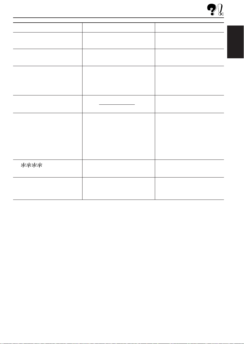
Symptoms
• “NO MAG” appears on the
display.
Causes
No magazine is loaded in the
CD changer.
Remedies
Insert the magazine.
• “NO DISC” appears on the
display.
• “RESET 8” appears on the
display.
• “RESET 1” – “RESET 7”
appears on the display.
• When “ERR 20” to “ERR 40”
appears on the display.
• “ ” appears on the
display.
• This unit does not work at all.
• The CD changer does not
work at all.
No CD is in the magazine.
This unit is not connected to a
CD changer correctly.
There is something blocking
the control cover movement.
Security lock is in use.
The built-in microcomputer
may function incorrectly due to
noise, etc.
Insert CD.
Connect this unit and the CD
changer correctly and press
the reset button of the CD
changer.
Press the reset button of the
CD changer.
Press the reset button on the
front panel. (See page 2.)
If the reset button does not
works, check the Installation/
Connection Manual (separate
volume). (Ex.: You have used a
longer screws than specified.)
Enter the password.
(See page 33.)
Press the reset button on the
front panel. (See page 2.)
ENGLISH
43
Page 44

MAINTENANCE
Handling CDs
This unit has been designed to reproduce the
CDs bearing the following marks.
ENGLISH
You can play back your original CD-Rs
(Recordable) and CD-RWs (Rewritable) on this
receiver.
This unit is not compatible with MP3.
How to handle CDs
When removing a CD from
its case, press down the
center holder of the case and
lift the CD out, holding it by
the edges.
• Always hold the CD by the
When storing a CD into its case, gently insert
the CD around the center holder (with the printed
surface facing up).
• Make sure to store CDs into the cases after
To keep CDs clean
A dirty CD may not play
correctly. If a CD does
become dirty, wipe it with a
soft cloth in a straight line
from center to edge.
COMPACT
DIGITAL AUDIO
Center holder
edges. Do not touch its recording surface.
use.
Moisture condensation
Moisture may condense on the lens inside the
CD player in the following cases:
• After starting the heater in the car.
• If it becomes very humid inside the car.
Should this occur, the CD player may
malfunction. In this case, eject the CD and leave
the unit turned on for a few hours until the
moisture evaporates.
When playing a CD-R or CD-RW
User-edited CD-Rs (Recordable) and CD-RWs
(Rewritable) can be played back only if they are
already “finalized. ”
• You can play back your original CD-Rs or
CD-RWs recorded in music CD format.
(However, they may not be played back
depending on their characteristics or recording
conditions.)
• Before playing back CD-Rs or CD-RWs, read
their instructions or cautions carefully.
• Some CD-Rs or CD-RWs may not be played
back on this unit because of their disc
characteristics, damage or stain on them, or if
the player’s lens is dirty.
• CD-Rs or CD-RWs are susceptible to high
temperatures or high humidity; so do not leave
them inside your car.
• CD-RWs may require a longer readout time.
(This is caused by the fact that the reflectance
of CD-RWs is lower than for regular CDs.)
To play new CDs
New CDs may have some
rough spots around the
inner and outer edges. If
such a CD is used, this
unit may reject the CD.
To remove these rough
spots, rub the edges with a
pencil or ball-point pen, etc.
About mistracking:
Mistracking may result from driving on extremely
rough roads. This does not damage the unit and
the CD, but will be annoying.
We recommend that you stop CD play while
driving on such rough roads.
44
CAUTIONS:
• Do not insert 8 cm CDs (single CDs) into the
loading slot. (Such CDs cannot be ejected.)
• Do not insert any CD of unusual shape – like a
heart or flower; otherwise, it will cause a
malfunction.
• Do not expose CDs to direct sunlight or any heat
source or place them in a place subject to high
temperature and humidity. Do not leave them in
a car.
• Do not use any solvent (for example,
conventional record cleaner, spray, thinner,
benzine, etc.) to clean CDs.
Page 45

SPECIFICATIONS
AUDIO AMPLIFIER SECTION
Maximum Power Output:
Front: 50 W per channel
Rear: 50 W per channel
Continuous Power Output (RMS):
Front: 19 W per channel into 4 Ω, 40 Hz
to 20 000 Hz at no more than
0.8% total harmonic distortion.
Rear: 19 W per channel into 4 Ω, 40 Hz
to 20 000 Hz at no more than
0.8% total harmonic distortion.
Load Impedance: 4 Ω (4 Ω to 8 Ω allowance)
Tone Control Range:
Bass: ±10 dB at 100 Hz
Treble: ±10 dB at 10 kHz
Frequency Response:40 Hz to 20 000 Hz
Signal-to-Noise Ratio:70 dB
Line-In Level/Impedance (only for KD-LX333R):
1.5 V/20 kΩ load
Line-Out Level/Impedance:
KD-LX333R: 4.0 V/20 kΩ load (full scale)
KD-LX111R: 2.0 V/20 kΩ load (full scale)
Output Impedance: 1 kΩ
TUNER SECTION
Frequency Range:
FM: 87.5 MHz to 108.0 MHz
AM: (MW) 522 kHz to 1 620 kHz
(LW) 144 kHz to 279 kHz
CD PLAYER SECTION
Type: Compact disc player
Signal Detection System: Non-contact optical
pickup (semiconductor laser)
Number of channels: 2 channels (stereo)
Frequency Response: 5 Hz to 20000 Hz
Dynamic Range: 96 dB
Signal-to-Noise Ratio: 98 dB
Wow and Flutter: Less than measurable limit
GENERAL
Power Requirement:
Operating Voltage: DC 14.4 V
(11 V to 16 V allowance)
Grounding System: Negative ground
Allowable Operating Temperature:
0°C to +40°C
Dimensions (W × H × D):
Installation Size:
182 mm × 52 mm × 160 mm
Panel Size:
188 mm × 58 mm × 8 mm
Mass: 1.8 kg (excluding accessories)
Design and specifications subject to change without
notice.
ENGLISH
[FM Tuner]
Usable Sensitivity: 11.3 dBf (1.0 µV/75 Ω)
50 dB Quieting Sensitivity:
16.3 dBf (1.8 µV/75 Ω)
Alternate Channel Selectivity (400 kHz):
65 dB
Frequency Response: 40 Hz to 15 000 Hz
Stereo Separation: 30 dB
Capture Ratio: 1.5 dB
[MW Tuner]
Sensitivity:20 µV
Selectivity:35 dB
[LW Tuner]
Sensitivity: 50 µV
45
Page 46

Having TROUBLE with operation?
Please reset your unit
Refer to page of How to reset your unit
Haben Sie PROBLEME mit dem Betrieb?
Bitte setzen Sie Ihr Gerät zurück
Siehe Seite Zurücksetzen des Geräts
Vous avez des PROBLÈMES de fonctionnement?
Réinitialisez votre appareil
Référez-vous à la page intitulée Comment réinitialiser votre appareil
Hebt u PROBLEMEN met de bediening?
Stel het apparaat terug
Zie de pagina met de paragraaf Het apparaat terugstellen
VICTOR COMPANY OF JAPAN, LIMITED
JVC
0102MNMMDTTKREN, GE, FR, NL
Page 47
Canceling the demonstration / Deaktivieren der Demonstration / Annulation de la démonstration /
De demonstratie annuleren
1234
SEL
S
ENGLISH
When shipped from the factory,
demonstration has been
activated, and starts automatically
when no operations are done for
about 20 seconds.
• It is recommended to cancel the
demonstration before you use
the unit for the first time.
To cancel the demonstration,
follow the procedure below.
1 Press and hold SEL (S) for
more than 2 seconds so that
one of the PSM items
appears on the display.
2 Select “DEMO MODE” if not
shown on the display.
3 Select “DEMO OFF.”
4 Finish the setting.
To activate the demonstration
again, repeat the same
procedure and select “DEMO ON”
in step 3.
DEUTSCH
Die Demonstration ist werkseitig
aktiviert und wird automatisch
gestartet, wenn das Gerät 20
Sekunden lang nicht genutzt wird.
• Wir empfehlen, die
Demonstration zu deaktivieren,
bevor Sie das Gerät zum ersten
Mal verwenden.
So deaktivieren Sie die
Demonstration:
1 Drücken Sie die Taste SEL
(S), und halten Sie sie länger
als 2 Sekunden gedrückt, bis
eine der PSM-Elemente im
Display angezeigt wird.
2 Wählen Sie „DEMO MODE“
(Demomodus) sofern nicht
bereits im Display angezeigt
wird.
3 Wählen Sie „DEMO OFF“
(Demo aus).
4 Bestätigen Sie die Einstellung.
Wenn Sie die Demonstration
wieder aktivieren wollen,
wiederholen Sie die obigen
Schritte und wählen „DEMO ON“
(Demo ein) in Schritt 3.
SEL
S
FRANÇAIS
À l’expédition de l’usine, la
démonstration est en service et
celle-ci démarre
automatiquement quand aucune
opération n’est effectuée pendant
environ 20 secondes.
• Il est recommandé d’annuler la
démonstration avant d’utiliser
l’appareil pour la première fois.
Pour annuler la démonstration,
suivez la procédure ci-dessous.
1 Maintenez pressée SEL (S)
pendant plus de 2 secondes
de façon que l’un des
éléments PSM apparaisse sur
l’affichage.
2 Choisissez “DEMO MODE”
s’il n’apparaît pas sur
l’affichage.
3 Choisissez “DEMO OFF”.
4 Terminez le réglage.
Pour mettre de nouveau la
démonstration en service,
répétez la même procédure et
choisissez “DEMO ON” à l’étape
3.
NEDERLANDS
Wanneer dit product de fabriek
verlaat, is demonstratie
geactiveerd. De demonstratie zal
automatisch starten wanneer er 20
seconden lang geen handelingen
worden uitgevoerd.
• Het is raadzaam de
demonstratie te annuleren
voordat u het apparaat voor het
eerst gebruikt.
Zo annuleert u de demonstratie,
moet u de onderstaande
procedure volgen:
1 Druk op SEL (S) in en houd
deze ten minste 2 seconden
ingedrukt, zodat een van de
PSM-vermeldingen op de
display wordt weergegeven.
2 Selecteer de vermelding
“DEMO MODE” als deze al
niet meteen op de display
wordt weergegeven.
3 Selecteer de vermelding
“DEMO OFF”.
4 Voltooi de instelling.
U activeert de demonstratie
opnieuw door dezelfde procedure
te herhalen en in stap 3 “DEMO
ON” te selecteren.
PTC004400
Page 48

KD-LX333R/KD-LX111R
Installation/Connection Manual
Einbau/Anschlußanleitung
Manuel d’installation/raccordement
Handleiding voor installatie/aansluiting
PIM171400
[E/EX]
0102MNMMDTTKR
JVC
EN, GE, FR, NL
ENGLISH
• This unit is designed to operate on 12 V DC,
NEGATIVE ground electrical systems.
INSTALLATION
(IN-DASH MOUNTING)
• The following illustration shows a typical
installation. However, you should make
adjustments corresponding to your specific
car. If you have any questions or require
information regarding installation kits, consult
your JVC IN-CAR ENTERTAINMENT dealer
or a company supplying kits.
1
Remove the trim plate.
2
Remove the sleeve after disengaging the
sleeve locks.
1 Stand the unit.
Note: When you stand the unit, be
careful not to damage the fuse on the
rear.
2 Insert the 2 handles between the unit
and the sleeve, as illustrated, to
disengage the sleeve locks.
3 Remove the sleeve.
Note: Be sure to keep the handles for
future use after installing the unit.
3
Attach the trim plate.
4
Install the sleeve into the dashboard.
* After the sleeve is correctly installed into
the dashboard, bend the appropriate
tabs to hold the sleeve firmly in place, as
illustrated.
5
Fix the mounting bolt to the rear of the
unit’s body and place the rubber cushion
over the end of the bolt.
6
Do the required electrical connections.
7
Slide the unit into the sleeve until it is
locked by pressing the four corners of the
trim plate.
Note: Do not press the panel (shaded in
the illustration); otherwise, the panel may
become unable to open or close.
DEUTSCH
• Dieses Gerät ist für einen Betrieb in
elektrischen Anlagen mit 12 V Gleichstrom
und (–) Erdung ausgelegt.
EINBAU
(IM ARMATURENBRETT)
• Die folgende Abbildung zeigt einen typischen
Einbau. Dennoch müssen Sie entsprechend
Ihrem jeweiligen Auto Anpassungen
vornehmen. Bei irgendwelchen Fragen oder
wenn Sie Informationen hinsichtlich des
Einbausatzes brauchen, wenden Sie sich an
ihren JVC Autoradiohändler oder ein
Unternehmen das diese Einbausätze vertreibt.
1
Den Frontrahmen herausnehmen.
2
Die Halterung nach dem Entriegeln der
Halterungensperren herausnehmen.
1 Das Gerät aufstellen.
Hinweis: Beim Aufstellen des Geräts
darauf achten, daß die Sicherung auf der
Rückseite nicht beschädigt wird.
2 Die 2 Griffe zwischen dem Gerät und der
Halterung wie abgebildet einstecken und
die Halterungensperren entriegeln.
3 Die Halterung herausnehmen.
Hinweis: Sicherstellen, daß die Griffe für
künftigen Gebrauch nach dem Einbau
des Geräts aufbewahrt werden.
3
Befestigen Sie die Frontrahmen.
4
Die Halterung im Armaturenbrett einbauen.
* Nach dem korrekten Einbau der Halterung
im Armaturenbrett, die entsprechenden
Riegel umknicken, um die Halterung an
ihrem Platz zu sichern, siehe Abbildung.
5
Die Befestigungsschraube an der Rückseite
des Gerätekörpers befestigen und das Ende
der Schraube mit einem Gummipuffer
abdecken.
6
Nehmen Sie die erforderlichen elektrischen
Anschlüsse vor.
7
Schieben Sie das Gerät in die Halterung.
Das Gerät wird verriegelt, indem Sie auf die
vier Ecken des Frontrahmen drücken.
Hinweis: Drücken Sie nicht auf die Blende
(die in der Abbildung dunkelgetönt
dargestellt ist); anderenfalls läßt sich die
Blende weder öffnen noch schließen.
FRANÇAIS
•
Cet appareil est conçu pour fonctionner sur
des sources de courant continu de 12 V à
masse NEGATIVE.
INSTALLATION (MONTAGE
DANS LE TABLEAU DE BORD)
•
L’illustration suivante est un exemple
d’installation typique. Cependant, vous devez
faire les ajustements correspondant à votre
voiture particulière. Si vous avez des
questions ou avez besoin d’information sur
des kits d’installation, consulter votre
revendeur d’autoradios JVC ou une
compagnie d’approvisionnement.
1
Retirer la plaque d’assemblage.
2
Libérer les verrous du manchon et retirer le
manchon.
1
Poser l’appareil à la verticale.
Remarque:
à la verticale, faire attention de ne pas
endommager le fusible situé sur l’arrière.
2
Insérer les 2 poignées entre l’appareil et
le manchon comme indiqué pour
désengagé les verrous de manchon.
3
Retirer le manchon.
Remarque:
poignées pour une utilisation ultérieur,
après l’installation de l’appareil.
3
Attachez la plaque d’assemblage.
4
Installer le manchon dans le tableau de bord.
* Après installation correcte du manchon
dans le tableau de bord, plier les bonnes
pattes pour maintenir fermement le
manchon en place, comme montré.
5
Monter le boulon de montage sur l’arrière du
corps de l’appareil puis passer l’amortisseur
en caoutchouc sur l’extrémité du boulon.
6
Réalisez les connexions électriques.
7
Faire glisser l’appareil dans le manchon
jusqu’à ce qu’il soit verrouillé en appuyant
sur les quatre coins de la plaque
d’assemblage.
Remarque:
(ombré sur l’illustration); sinon le panneau
risquerait de ne pas pouvoir s’ouvrir ou se
fermer.
Lorsque vous mettez l’appareil
S’assurer de garder les
N’appuyez pas sur le panneau
NEDERLANDS
• Dit apparaat mag worden gebruikt bij elektrische
systemen die werken op 12 V gelijkstroom met
negatieve aarding.
INSTALLATIE (INBOUW IN
HET DASHBOARD)
• Op de volgende afbeelding kunt u zien hoe de
installatie, normaal gesproken, in zijn werk gaat. U
moet echter bij de installatie rekening houden met
de bijzonderheden van uw eigen auto. Neem bij
vragen of voor meer bijzonderheden over
inbouwpakketten contact op met uw JVC car audio
dealer of een dealer of een bedrijf dat
inbouwpakketten levert.
1
Verwijder de sierplaat.
2
Verwijder het huis nadat u de klemmen hebt
losgemaakt.
1 Zet het apparaat rechtop.
Opmerking: Wanneer u het apparaat
rechtop zet, moet u erop letten dat u de
zekering aan de achterkant niet beschadigt.
2 Plaats de 2 hendels, zoals afgebeeld, tussen
het apparaat en het huis, om de klemmen los
te maken.
3 Verwijder het huis.
Opmerking: Bewaar de hendels nadat u het
apparaat hebt geïnstalleerd, zodat u ze ook in
de toekomst kunt gebruiken.
3
Bevestig de sierplaat.
4
Installeer het huis in het dashboard.
* Nadat het huis op de juiste wijze in het
dashboard is geplaatst, moet u de palletjes,
zoals afgebeeld, stevig op hun plaats duwen.
5
Maak de bevestigingsbout aan de achterkant van
het apparaat vast en plaats de rubberdop over het
uiteinde van de bout.
6
Breng de vereiste elektrische verbindingen tot
stand.
7
Schuif het apparaat in het huis totdat het
vergrendeld is, kunt u deze vastzetten door op de
vier hoeken van de sierplaat te drukken.
Opmerking: Druk niet op het paneel zelf
(gearceerd weergegeven in de illustratie); anders
kunt u het paneel zodanig beschadigen dat dit
niet meer kan worden geopend en gesloten.
1
2
Slot
Schlitz
Fente
Sleuf
Trim plate
Frontrahmen
Plaque d’assemblage
Sierplaat
Handle
Griff
Poignée
Hendel
Fuse
Sicherung
Fusible
Zekering
Lock Plate
Arretierplättchen
Plaque de verrouillage
Vergrendelingsplaat
Sleeve
Halterung
Manchon
Huis
3
Trim plate
Frontrahmen
Plaque d’assemblage
Sierplaat
Rubber cushion
Gummipuffer
Amortisseur en caoutchouc
Rubberdop
Sleeve
Halterung
Manchon
Huis
4
7
4
Dashboard
Armaturenbrett
Tableau de bord
Dashboard
184 mm
53 mm
Mounting bolt
Befestigungsschraube
5
See “ELECTRICAL CONNECTIONS. ”
Siehe „ELEKTRISCHE ANSCHLÜSSE“.
Référez-vous “RACCORDEMENTS
*
6
ELECTRIQUES” .
Zie “ELEKTRISCHE VERBINDINGEN”.
Boulon de montage
Bevestigingsbout
TROUBLESHOOTING
• The fuse blows.
* Are the red and black leads connected correctly?
• Power cannot be turned on.
* Is the yellow lead connected?
• No sound from the speakers.
* Is the speaker output lead short-circuited?
• Sound is distorted.
* Is the speaker output lead grounded?
* Are the “–” terminals of L and R speakers grounded
in common?
• Unit becomes hot.
* Is the speaker output lead grounded?
* Are the “–” terminals of L and R speakers grounded
in common?
FEHLERSUCHE
• Die Sicherung brennt durch.
* Sind die roten und schwarzen Leitungen richtig
angeschlossen?
• Stromversorgung kann nicht eingeschaltet
werden.
* Ist die gelbe Leitung angeschlossen?
• Kein Ton aus den Lautsprechern.
* Ist die Lautsprecherausgangsleitung
kurzgeschlossen?
• T on verzerrt.
* Ist die Lautsprecherausgangsleitung geerdet?
* Sind die (–) Anschlußklemmen der linken und
rechten Lautsprecher zusammen geerdet?
• Gerät wird heiß.
* Ist die Lautsprecherausgangsleitung geerdet?
* Sind die (–) Anschlußklemmen der linken und
rechten Lautsprecher zusammen geerdet?
EN CAS DE DIFFICULTES
• Le fusible saute.
*
Les fils rouge et noir sont-ils racordés
correctement?
• L’appareil ne peut pas être mise sous tension.
*
Le fil jaune est-elle raccordée?
• Pas de son des enceintes.
*
Le fil de sortie d’enceinte est-il court-circuité?
• Le son est déformé.
*
Le fil de sortie d’enceinte est-il à la masse?
*
Les bornes “–” des enceintes gauche et droit sontelles mises ensemble à la masse?
• L’appareil devient chaud.
*
Le fil de sortie d’enceinte est-il à la masse?
*
Les bornes “–” des enceintes gauche et droit sontelles mises ensemble à la masse?
1
PROBLEMEN OPLOSSEN
• De zekering slaat door.
* Zijn de rode en de zwarte draden op de juiste manier
aangesloten?
• De stroom kan niet worden ingeschakeld.
* Is de gele draad aangesloten?
• Er komt geen geluid uit de speakers.
* Is de uitgaande speakerdraad kortgesloten?
• Het geluid wordt vervormd.
* Is de uitgaande speakerdraad geaard?
* Zijn de minpolen van de linker- en de rechterspeakers
gemeenschappelijk geaard?
• Het apparaat raakt verhit.
* Is de uitgaande speakerdraad geaard?
* Zijn de minpolen van de linker- en de rechterspeakers
gemeenschappelijk geaard?
Page 49

• When using the optional stay
• Beim Verwenden der Anker-Option
• Lors de l’utilisation du hauban en option
• Wanneer u de steun gebruikt (facultatief)
Washer
Unterlegscheibe
Rondelle
Sluitring
Dashboard
Armaturenbrett
Tableau de bord
Dashboard
Fire wall
Feuerwand
Cloison
Brandscherm
Sleeve
Halterung
Manchon
Huis
Mounting bolt
Befestigungsschraube
Boulon de montage
Bevestigingsbout
Stay (option)
Anker (Option)
Hauban (en option)
Steun (facultatief)
Lock nut
Sicherungsmutter
Ecrou d’arrêt
Contra-moer
Screw (option)
Schraube (Option)
Vis (en option)
Schroef (facultatief)
• When installing the unit without using the sleeve
• Beim Einbau des Geräts ohne Halterung
• Lors de l’installation de l’appareil scans utiliser de manchon
• Wanneer u het apparaat zonder huis installeert
In a Toyota for example, first remove the car radio and install the unit in its place.
Zum Beispiel in einem Toyota zuerst das Autoradio ausbauen und dann das Gerät an seinem Platz einbauen.
Par exemple dans une Toyota, retirer d’abord l’autoradio et installer l’appareil à la place.
Voorbeeld: Bij een Toyota moet u eerst de autoradio verwijderen en daarna het apparaat installeren.
Note: When installing the unit on the mounting bracket, make sure to use the 6 mm-long screws. If longer screws are
Hinweis: Beim Anbringen des Gerät an der Konsole sicherstellen, daß 6 mm lange Schrauben verwendet werden.
Remarque:
Opmerking: Wanneer u het apparaat aan de bevestigingsklem vastmaakt, moet u de 6 mm lange schroeven gebruiken. Als u langere
Flat type screws (M5 x 6 mm)*
Senkkopfschrauben (M5 x 6 mm)*
Vis à tête plate (M5 x 6 mm)*
Platkopschroeven (M5 x 6 mm)*
Bracket*
Konsole*
Support*
Console*
Pocket
Taschen
Poche
Zak
used, they could damage the unit.
Werden längere Schrauben verwendet, können sie das Gerät beschädigen.
Lors de l’installation de l’appareil sur le support de montage, s’assurer d’utiliser des vis d’une longueur de
6 mm. Si des vis plus longues sont utilisées, elles peuvent endommager l’appareil.
schroeven gebruikt, kan het apparaat worden beschadigd.
* Not included with this unit.
* Nicht Teil dieses Geräts.
*
Non fourni avec cet appareil.
* Niet meegeleverd.
Flat type screws (M5 x 6 mm)*
Senkkopfschrauben (M5 x 6 mm)*
Vis à tête plate (M5 x 6 mm)*
Platkopschroeven (M5 x 6 mm)*
Bracket*
Konsole*
Support*
Console*
Removing the unit
• Before removing the unit, release the rear
section.
1
Remove the trim plate.
2
Insert the 2 handles into the slots, as
shown. Then, while gently pulling the
handles away from each other, slide out the
unit. (Be sure to keep the handles after
installing it.)
1
Trim plate
Frontrahmen
Plaque d’assemblage
Sierplaat
Parts list for installation and
connection
The following parts are provided with this unit.
After checking them, please set them correctly.
Sleeve
Halterung
Manchon
Huis
Trim plate
Frontrahmen
Plaque d’assemblage
Sierplaat
Ausbau des Geräts
• Vor dem Ausbau des Geräts den hinteren Teil
freigeben.
1
Den Frontrahmen herausnehmen.
2
Die 2 Griffe in die Schlitze wie gezeigt
stecken. Dann die Griffe behutsam
auseinander ziehen und das Gerät
herausziehen. (Die Griffe nach dem
Einbau auf jeden Fall aufbewahren.)
Teileliste für den Einbau und
Anschluß
Die folgenden Teile werden zusammen mit
diesem Gerät geliefert.
Nach ihrer Überprüfung, die Teile richtig
einsetzen.
Handles
Griffe
Poignées
Hendels
Retrait de l’appareil
•
Av ant de retirer l’appareil, libérer la section arrière.
1
Retirer la plaque d’assemblage.
2
Introduire les 2 poignées dans les fentes,
comme montré. Puis, tout en tirant
doucement les poignées écartées, faire
glisser l’appareil pour le sortir.
(S’assurer
de conserver les poignées après
l’installation de l’appareil.)
2
Handle
Griff
Poignée
Hendel
Liste des pièces pour l’installation et
raccordement
Les pièces suivantes sont fournies avec cet
appareil.
Après vérification, veuillez les placer
correctement.
Power cord
Stromkable
Cordon d’alimentation
Stroomkabel
Verwijderen van het apparaat
• Voordat u het apparaat verwijdert, moet u het
achtergedeelte losmaken.
1
Verwijder de sierplaat.
2
Plaats de 2 hendels, zoals afgebeeld, in de
sleuven. Daarna duwt u de hendels zachtjes uit
elkaar en kunt u het apparaat naar buiten schuiven.
(Bewaar de hendels nadat u het apparaat
hebt geïnstalleerd!)
Lijst van onderdelen die u bij
installatie en aansluiting nodig hebt
De volgende onderdelen worden bij het apparaat
geleverd.
Installeer ze op de juiste wijze, nadat u ze hebt
gecontroleerd.
Remote controller
Fernbedienung
Télécommande
Afstandsbediening
Battery
Batterie
Pile
Batterij
CR2025
Washer (ø5)
Unterlegscheibe(ø5)
Rondelle (ø5)
Sluitring (ø5)
Lock nut (M5)
Sicherungsmutter (M5)
Ecrou d’arrêt (M5)
Contra-moer (M5)
ELECTRICAL CONNECTIONS
To prevent short circuits, we recommend that you
disconnect the battery’s negative terminal and
make all electrical connections before installing the
unit. If you are not sure how to install this unit
correctly, have it installed by a qualified technician.
Note:
This unit is designed to operate on 12 V DC,
NEGATIVE ground electrical systems. If your
vehicle does not have this system, a voltage
inverter is required, which can be purchased at JVC
IN-CAR ENTERTAINMENT dealers.
• Replace the fuse with one of the specified rating.
If the fuse blows frequently, consult your JVC INCAR ENTERTAINMENT dealer.
• If noise is a problem...
This unit incorporates a noise filter in the power
circuit. However, with some vehicles, clicking or
other unwanted noise may occur. If this happens,
connect the unit’s rear ground terminal (see
connection diagram) to the car’s chassis using
shorter and thicker cords, such as copper braiding
or gauge wire. If noise still persists, consult your
JVC IN-CAR ENTERTAINMENT dealer.
• Maximum input of the speakers should be no
more than 50 W at the rear and 50 W at the front,
with an impedance of 4 Ω to 8 Ω.
• Be sure to ground this unit to the car’s
chassis.
• The heat sink becomes very hot after use. Be
careful not to touch it when removing this unit.
Heat sink
Abstrahlblech
Dissipateur de chaleur
Warmte-opnemer
Mounting bolt (M5 x 20 mm)
Befestigungsschraube (M5 x 20 mm)
Boulon de montage (M5 x 20 mm)
Bevestigingsbout (M5 x 20 mm)
ELEKTRISCHE ANSCHLÜSSE
Zur Vermeidung von Kurzschlüssen empfehlen
wir, daß Sie den negativen Batterieanschluß
abtrennen und alle elektrischen Anschlüsse
herstellen, bevor das Gerät eingebaut wird. Sind
Sie sich über den richtigen Einbau des Geräts
nicht sicher, lassen Sie es von einem qualifizierten
Techniker einbauen.
Hinweis:
Dieses Gerät ist für einen Betrieb in elektrischen
Anlagen mit 12 V Gleichstrom und (–) Erdung
ausgelegt. Verfügt Ihr Fahrzeug nicht über diese
Anlage, ist ein Spannungsinverter erforderlich, der
bei JVC Autoradiohändler erworben werden kann.
• Die Sicherung mit einer der entsprechenden
Nennleistung ersetzen. Brennt die Sicherung
häufig durch, wenden Sie sich an ihren JVC
Autoradiohändler.
• Sind Störgeräusche ein Problem...
Dieses Gerät enthält ein Störfilter im Stromkreis.
Bei manchen Fahrzeugen kann jedoch ein
Klicken oder andere unerwünschte
Störgeräusche auftreten. Sollte das der Fall sein,
die hintere Erdungscanschlußklemme (siehe
Schaltplan) des Geräts am Fahrwerk des Fahrzeugs
anschließen, dabei kürzere und dickere Kabel wie
beispielsweise Kupfergeflechtdraht oder Stahldraht
verwenden. Bleibt Störgeräusch bestehen, wenden
Sie sich an Ihren JVC Autoradiohändler.
• Maximale Eingangsleistung der Lautsprecher
sollte nicht mehr als 50 W hinten und 50 W
vorne sein, mit einer Impedanz von 4 Ω bis 8 Ω.
• Sicherstellen, daß das Gerät am Fahrwerk
geerdet wird.
• Das Abstrahlblech wird nach dem Gebrauch
sehr heiß. Beim Ausbau des Geräts darauf
achten, das Abstrahlblech nicht zu berühren.
Rubber cushion
Gummipuffer
Amortisseur en caoutchouc
Rubberdop
RACCORDEMENTS ELECTRIQUES
Pour éviter tout court-circuit, nous vous
recommandons de débrancher la borne négative
de la batterie et d’effectuer tous les raccordements
électriques avant d’installer l’appareil. Si l’on n’est
pas sûr de pouvoir installer correctement cet
appareil, le faire installer par un technicien qualifié.
Remarque:
Cet appareil est conçu pour fonctionner sur des
sources de courant continu de
NEGATIVE
d’alimentation, il vous faut un convertisseur de
tension, que vous pouvez acheter chez un
revendeur d’autoradios JVC.
•
Remplacer le fusible par un de la valeur
précisée. Si le fusible saute souvent, consulter
votre revendeur d’autoradios JVC.
•
Si le bruit est un problème...
Cet appareil incorpore un filtre de bruit dans le
circuit d’alimentation. Cependant, avec certains
véhicules, quelques claquements ou autres
bruits non désirés risquent de se produire. Si
cela arrive, raccorder la
masse
le diagramme de raccordement) en utiliscant des
cordons les plus gros et les plus courts
possibles telle qu’une barre de cuivre ou une
tresse. Si le bruit persiste, consulter votre
revendeur d’autoradios JVC.
•
La puisscance admissible des enceintes devrait
n’être pas plus qu’ c 50 W à l’arrière et à 50 W
l’avant, avec une impédance de
• S’assurer de raccorder la mise à la masse de
cet appareil au châssis de la voiture.
Le dissipateur de chaleur devient très chaud
•
après usage. Faire attention de ne pas le
toucher en retirant cet appareil.
. Si votre véhicule n’offre pas ce type
de l’appareil au châssis de la voiture (voir
12 V à masse
borne arrière de
4 Ω à 8 Ω
.
Only for KD-LX333R
Ausschliesslich Modell KD-LX333R
Seulement pour le KD-LX333R
Uitsluitend voor de KD-LX333R
ELEKTRISCHE VERBINDINGEN
Om kortsluiting te voorkomen adviseren wij u om de
minpool van de accu los te maken en alle elektrische
verbindingen tot stand te brengen voordat u het apparaat
in de auto installeert. Als u niet zeker weet hoe u dit
apparaat moet installeren, kunt u dit beter door een
daartoe gekwalificeerde technicus laten doen.
Opmerking:
Dit apparaat mag worden gebruikt bij elektrische
systemen die werken op 12 V gelijkstroom met
negatieve aarding. Als uw auto niet is uitgerust met
een dergelijk systeem, is een spanningsomzetter vereist.
Dit instrument kan worden aangeschaft bij JVC car audio
dealers.
• Vervang de zekering door een exemplaar met het
aangegeven vermogen. Als de zekering vaak doorslaat,
moet u uw JVC car audio dealer raadplegen.
• Als u geluidsproblemen hebt…
De krachtschakeling van dit apparaat heeft een
ingebouwd geluidsfilter. In sommige voertuigen zijn
tikgeluiden of andere ongewenste geluiden te horen. Als
dit gebeurt, moet u de massaklem aan de
achterkant (zie aansluitingsschema) aan het chassis
van de auto vastmaken met behulp van een kortere en
dikkere kabel, zoals kopermanteldraad of tellerkabel.
Als het geluid niet verdwijnt, moet u contact opnemen
met uw JVC car audio dealer.
• Het maximum ingangsvermogen van de speakers moet
achterin niet meer dan 50 W zijn en voorin 50 W, met
een impedantie van 4 Ω tot 8 Ω.
• Zorg ervoor dat dit apparaat door middel van
een aardkabel is verbonden met het chassis
van de auto.
• De warmte-opnemer kan na gebruik erg heet worden.
Raak de warmte-opnemer niet aan wanneer u dit
apparaat van zijn plaats haalt.
Connecting the leads / Anschließen der Leitungen / Raccordement des fils / Aansluiting van de gekleurde draden
Twist the core wires when connecting.
Die Kerndrähte beim Anschließen
verdrehen.
Torsader les âmes des fils en les
raccordant.
Draai de kerndraden om elkaar heen
wanneer u ze wilt aansluiten.
Solder the core wires to connect them securely.
Die Kerndrähte anlöten, um sie fest anzuschließen.
Souder les âmes des fils pour les raccorder entre eux
de façon sûre.
Soldeer de kerndraden zodat ze stevig vast zitten.
2
CAUTION / VORSICHT / PRECAUTION / LET OP!:
• To prevent short-circuit, cover the terminals of the UNUSED leads with insulating tape.
• Zur Vermeidung eines Kurzschlusses die Anschlußklemmen der NICHT
VERWENDETEN Leitungen mit Isolierklebeband umwickeln.
•
Pour éviter les court-circuits, couvrir les bornes des fils qui ne sont PAS utilisés
avec de la bande isolante.
• Om kortsluiting te voorkomen, moet u de aansluitklemmen van ONGEBRUIKTE
gekleurde draden met isolatieband bedekken.
Page 50

ENGLISH
A If your car is equipped with the ISO connecter
Wenn Ihr Auto mit ISO-Steckern ausgestattet ist
Si votre voiture est équippée d’un connecteur ISO
Indien uw auto is uitgerust met de ISO-connector
• Connect the ISO connectors as illustrated.
• Die ISO-Stecker wie abgebildet anschließen.
Connectez les connecteurs ISO comme montré sur l’illustration.
•
• Sluit de ISO-connectoren aan zoals op het voorbeeld is aangegeven.
A1
B1
A2
B2
A3
B3
A4
B4
ISO connector of the supplied power cord
A1
B1
A2
B2
A3
B3
A4
B4
View from the lead side
Ansicht von der Leitungsseite
Vue à partir du côté des fils
Aanzicht vanaf het snoer
ISO-Stecker am Stromkabel
Connecteur ISO pour le cordon
d’alimentation fourni
ISO-connector van het meegeleverde snoer
DEUTSCH
From the car body
Von der Karosserie
De la carrosserie de la voiture
Vanaf de auto
FRANÇAIS
NEDERLANDS
For some VW/Audi or Opel (Vauxhall) automobile
Für manche VW/Audi oder Opel (Vauxhall) Fahrzeuge
Pour certaine voiture VW/Audi ou Opel (Vauxhall)
Voor bepaalde modellen VW/Audi of Opel (Vauxhall) geldt
You may need to modify the wiring of the supplied power cord as illustrated.
• Contact your authorized car dealer before installing this unit.
Sie müssen evtl. die Verdrahtung des mitgelieferten Stromkabels wie abgebildet ändern.
• Wenden Sie sich an Ihre Vertragswerkstatt, bevor Sie das Gerät einbauen.
Vous aurrez peut-être besoin de modifier le câblage du cordon d’alimentation fourni comme montré sur l’illustration.
•
Contactez votre revendeur automobile autorisé avant d’installer l’appareil.
Wellicht moet u de bedrading van het meegeleverde snoer als in het voorbeeld aanpassen.
• Neem contact op met uw offici’le autodealer alvorens dit apparaat te installeren.
Original wiring
Originalverdrahtung
Câblage original
Originele bedrading
Modified wiring 1
Geänderte
Verdrahtung 1
Câblage modifié
Aangepaste bedrading 1
Modified wiring 2
Geänderte
Verdrahtung 2
Câblage modifié
Aangepaste bedrading 2
1
2
ISO connector
ISO-Stecker
Connecteur ISO
ISO-connector
Yellow/Gelb
Red/
Rot/
Rouge/
Rood
Yellow/Gelb
Red/Rot/
Rouge/
Rood
Red/Rot/
Rouge/
Rood
/Jaune/
Geel Yellow/Gelb
Red/Rot/
Rouge/
Rood
/Jaune/
Geel
Red/Rot/
Rouge/
Rood
/Jaune/
Geel
Red/Rot/
Rouge/
Rood
Red/Rot/
Yellow/Gelb
Red/Rot/
Yellow/Gelb
/Jaune/
Rouge/
/Jaune/
Rouge/
/Jaune/
Red/Rot/
Rouge/
Geel
Rood
Geel
Rood
GeelYellow/Gelb
Rood
Use modified wiring 2 if the unit does not turn on.
Geänderte Verdrahtung 2 verwenden, wenn das
Gerät so nicht an geht.
Utilisez le câblage modifié 2 si l’appareil ne se met
pas sous tension.
Pas de bedrading 2 aan indien het apparaat niet reageert
bij inschakelen.
B Connections without using the ISO connecters / Anschlüsse ohne ISO-Stecker / Connexions sans l’utilisation des connecteurs ISO / Verbindingen
zonder ISO-connectoren
Before connecting: Check the wiring in the vehicle
carefully. Incorrect connection may cause serious
damage to this unit.
The leads of the power cord and those of the connector
from the car body may be different in colour.
1
Cut the ISO connector.
2
Connect the colored leads of the power cord to the
car battery, speakers and power aerial (if any) in the
following sequence.
1 Black: ground
2 Yellow: to car battery (constant 12 V)
3 Red: to an accessory terminal
4 Blue with white stripe: to power aerial (200 mA
max.)
5 Orange with white stripe: to car light control
switch
6 Brown: to cellular phone system (for details, refer
to the instructions of the cellular phone.)
7 Others: to speakers
3
Connect the aerial cord.
4
Finally connect the wiring harness to the unit.
Cut the ISO connector
1
Aerial terminal
Antennenanschlußklemme
Borne de l’antenne
Aansluitpunt antenne
Rear ground terminal
Hintere Erdungscan–
schlußklemme
Borne arrière de
masse
Massaklem aan de
achterkant
LINE OUT
(see diagram C )
(siehe Schaltplan C )
(voir le diagramme C )
(zie schema C )
*1: Before checking the operation of this unit prior to installation,
this lead must be connected, otherwise power cannot be
turned on.
*1: Vor der Überprüfung der Funktionsfähigkeit des Geräts vor
dem Einbau, muß diese Leitung angeschlossen werden,
da sonst die Stromversorgung nicht eingeschaltet werden
kann.
*1: Pour vérifier le fonctionnement de cet appareil avant
installation, ce fil doit être raccordé, sinon l’appareil ne peut
pas être mis sous tension.
*1: Voordat u controleert of het apparaat werkt (alvorens het te
installeren), moet deze draad aangesloten zijn. Als dit niet het
geval is, kan de stroom niet worden ingeschakeld.
SUBWOOFER OUT
(KD-LX333R)
(see diagram C )
(siehe Schaltplan C )
(voir le diagramme C )
(zie schema C )
LINE IN (KD-LX333R)
(see diagram C )
(siehe Schaltplan C )
(voir le diagramme C )
(zie schema C )
Den ISO Stecker abscheiden
Coupez le connecteur ISO
Knip de connector los
To aerial
Zur Antenne
A l’antenne
Naar de antenne
2
Vor dem Anschließen: Die Verdrahtung im Fahrzeug
sorgfältig überprüfen. Falsche Anschlüsse können
ernsthafte Schäden am Gerät hervorrufen.
Die Leiter des Stromkabels und die Leiter des
Anschlusses im Fahrzeug können sich farblich
unterscheiden.
1
Den ISO-Stecker abschneiden.
2
Die farbigen Leitungen des
Spannunsgversorgungskabels an der Autobatterie,
den Lautsprechern und dem Motorantenne (sofern
vorhanden) in folgender Reihenfolge anschließen.
1 Schwarz: Erdung
2 Gelb: an Autobatterie (konstant 12 V)
3 Rot: zur einer Zubehöranschlußklemme
4 Blau mit weißem Streifen: zur Motorantenne
(max. 200 mA)
5 Orange mit weißem Streifen: zur Autolichtschalter
6 Braun: zur Mobiltelefon (weitere informationen
entnehmen Sie bitte der Bedienungscanleitung
des Mobiltelefons.)
7 Andere: zur Lautsprecher
3
Das Antennenkabel anschließen.
4
Die Kabelbäume am Gerät anschließen.
CD changer or another external
component
CD-Wechsler oder eine andere
externe Komponente
Changeur CD JVC ou autre appareil
3
15
15 A fuse
15 A Sicherung
Fusible 15 A
Zekering 15 A
extérieur
CD-wisselaar of een ander extern
apparaat
4
Black
Schwarz
Noir
A4
Zwart
1
1
Yellow*
1
Gelb*
1
Jaune*
1
Geel *
Red
Rot
Rouge
Rood
Blue with white stripe
Blau mit weißem Streifen
Bleu avec bande blanche
Blauw met witte streep
Orange with white stripe
Orange mit weißem Streifen
Orange avec bande blanche
Oranje met witte streep
Brown / Braun /
A2
Marron /
To metallic body or chassis of the car
Zur metallenen Karosserie oder zum Fahrwerk des Autos
Au corps métallique ou châssis de la voiture
Naar metalen ondergrond of chassis van de auto
To a live terminal in the fuse block connecting to the car battery
(bypassing the ignition switch)
Zur einer stromführenden Anschlußklemme im Sicherungsblock zum
Anschließen an die Autobatterie (Umgehen des Zündschalters)
2
À une borne sous tension du porte-fusible connectée à la batterie de la
voiture (en dérivant l’interrupteur d’allumage)
Naar een onder spanning staande aansluitklem in het zekeringblok die is
aangesloten op de accu van de auto (u passeert de ontstekingsschakelaar)
B4
3
Avant de commencer la connexion:
attentivement le câblage du véhicule. Une connexion
incorrecte peut endommager sérieusement l’appareil.
Le fil du cordon d’alimentation et ceux des connecteurs
du châssis de la voiture peuvent être différents en couleur .
1
Coupez le connecteur ISO.
2
Connectez les fils de couleur du cordon
d’alimentation à la batterie de la voiture, aux
enceintes et à l’antenne automatique (s’il y en a
une) dans l’ordre suivant.
1
Noir: à la masse
2
Jaune: à la batterie de la voiture (12 V constant)
3
Rouge: à une borne accessoire
4
Bleu avec bande blanche: à l’antenne
automatique (200 mA max.)
5
Orange avec bande blanche: à l’interrupteur
d’éclairage de la voiture
6
Marron: à un système de téléphone cellulaire
(pour les détails, se référer aux instructions du
téléphone cellulaire.)
7
Autres: aux enceintes
3
Connectez le cordon d’antenne.
4
Finalement, connectez le faisceau de fils à l’appareil.
When connecting a CD changer, we recommend to use one of the CH-X series CD changers.
• If your CD changer is one of the KD-MK series, you need an optional cord (KS-U15K).
You can also use an external component such as a portable MD player by connecting the Line Input Adaptor
KS-U57 (not supplied). (See diagram C .) (Only for KD-LX111R.)
Wenn Sie einen CD-Wechsler anschließen möchten, empfiehlt es sich, einen CD-Wechsler der Modellreihe
CH-X zu verwenden.
• Wenn Ihr CD-Wechsler zur Modellreihe KD-MK gehören, benötigen Sie ein anderes Kabel (KS-U15K).
Sie können auch eine externe Komponente, z.B. einen tragbaren MD-Spieler, verwenden, wenn Sie den (nicht
zum Lieferumfang gehörenden) Line-Eingangsadapter KS-U57 anschließen. (Siehe Schaltplan C .)
(Ausschliesslich Modell KD-LX111R.)
Lors de la connexion d’un changeur CD , nous v ous recommandons d’utiliser un des changeurs CD de la série CH-X.
• Si votre changeur appartient à la série KD-MK, vous avez besoin d’un cordon optionnel (KS-U15K).
Vous pouvez aussi utiliser un appareil extérieur tel qu’un lecteur de MD en connectant l’adaptateur d’entrée de
ligne KS-U57 (non fourni). (Voir le diagramme C..) (Seulement pour le KD-LX111R.)
Voor het aansluiten van een CD-wisselaar raden we een wisselaar uit de CH-X-serie aan.
• Als de CD-wisselaar die u wilt aansluiten uit de KD-MK-serie komt, hebt u een extra kabel nodig (KS-U15K).
Het is ook mogelijk een extern apparaat zoals een draagbare MD-speler aan te sluiten met behulp van de Line Input
Adapter KS-U57 (niet meegeleverd). (Zie schema C .) (Uitsluitend voor de KD-LX111R.)
Not included with this unit / Wird nicht mit Gerät mitgeliefert /
*
Non fourni avec cet appareil
To an accessory terminal in the fuse block
Zur einer Zubehöranschlußklemme im Sicherungsblock
À une borne accessoire du porte-fusible
Naar een aansluitklem in het zekeringblok
B3
Bruin
To power aerial if any
Zur Motorantenne, sofern vorhanden
4
À l’antenne automatique s’il y en a une
Naar de antenne (indien aanwezig)
/ Niet bij het apparaat inbegrepen
Vérifiez
(ILLUMINATION)
Alvorens de verbindingen tot stand te brengen:
Moet u de bedrading in de auto zorgvuldig. Het apparaat kan
door verkeerde verbindingen ernstige schade oplopen.
De draden van het stroomsnoer verschillen mogelijk van
kleur metde aansluitingen op het chassis van de auto.
1
Knip de ISO-connector los.
2
Sluit de gekleurde snoerdraden van de stroomkable in de
hierna genoemde volgorde aan op de accu van de auto,
de luidsprekers en de antenne (indien aanwezig).
1 Zwart: aarde
2 Geel: naar de accu van de auto (constant 12 V)
3 Rood: naar de aansluitklem van de accessoire
4 Blauw met witte streep: naar de antenne
(Max. 200 mA)
5 Oranje met witte streep: naar de schakelaar voor de
autoverlichting
6 Bruin: naar het mobiele-telefoonsysteem (lees voor
meer informatie de instructies die bij de mobiele
telefoon worden geleverd.)
7 Andere: naar de speakers
3
Sluit de antenne aan.
4
Verbind de draadbundel daarna met het apparaat.
Ignition switch
*
*
A3
5
A1
6
Zündschalter
Interrupteur d’allumage
Contactschakelaar
Fuse block
Sicherungsblock
Porte-fusible
Zekeringblok
To car light control switch
Zur Autolichtschalter
À l’interrupteur d’éclairage de la voiture
Naar de schakelaar voor de autoverlichting
To cellular phone system
Zur Mobiltelefon
À un système de téléphone cellulaire
Naar het mobiele-telefoonsysteem
White with black stripe
Weiß mit schwarzem Streifen
Blanc avec bande noire
Wit met zwarte streep
A3
B3
White
Weiß
Blanc
Wit
Left speaker (front)
Linker Lautsprecher (vorne)
Enceinte gauche (avant)
Linkerspeaker (voorin)
7
Gray with black stripe
Grau mit schwarzem Streifen
Gris avec bande noire
Grijs met zwarte streep
B2 A4
A2
Green with black stripe
Gray
Grün mit schwarzem
Grau
Streifen
Gris
V ert avec bande noire
Grijs
Groen met zwarte streep
Right speaker (front)
Rechter Lautsprecher (vorne)
Enceinte droit (avant)
Rechterspeaker (voorin)
3
B4
Green
Purple with black stripe
Grün
Lila mit schwarzem
Vert
Streifen
Groen
Violet avec bande noire
Paars met zwarte streep
Left speaker (rear)
Linker Lautsprecher (hinten)
Enceinte gauche (arrière)
Linkerspeaker (achterin)
A1
B1
Purple
Lila
Violet
Paars
Right speaker (rear)
Rechter Lautsprecher
(hinten)
Enceinte droit (arrière)
Rechterspeaker (achterin)
Page 51

PRECAUTIONS on power supply and
speaker connections:
• DO NOT connect the speaker leads of the power
cord to the car battery; otherwise, the unit will
be seriously damaged.
• Connect the black lead (ground), yellow lead (to car
battery, constant 12 V), and red lead (to an
accessory terminal) correctly.
• BEFORE connecting the speaker leads of the
power cord to the speakers, check the speaker
wiring in your car.
– If the speaker wiring in your car is as
illustrated in Fig. 1 and Fig. 2 below, DO NOT
connect the unit using that original speaker
wiring. If you do, the unit will be seriously
damaged.
Redo the speaker wiring so that you can connect
the unit to the speakers as illustrated in Fig. 3.
– If the speaker wiring in your car is as
illustrated in Fig. 3, you can connect the unit
using the original speaker wiring in your car.
– If you are not sure of the speaker wiring of your car ,
consult your JVC IN-CAR ENTERTAINMENT dealer.
+
+
L
-
-
+
+
R
-
-
+
+
L
-
-
+
+
R
-
-
Fig. 1 Fig. 2 Fig. 3
+
L
-
+
R
-
VORSICHTSMASSREGELN beim
Anschließen der Stromversorgung
und Lautsprecher:
• Die Lautsprecherleitungen des Netzkabels
NICHT an der Autobatterie anschließen, da
sonst das Gerät schwer beschädigt wird.
• Die schwarze Leitung (Erdung), die gelbe Leitung
(zur Autobatterie, konstant 12 V) und die rote
Leitung (zur Zubehöranschlußklemme) richtig
anschließen.
• VOR dem Anschließen der Lautsprecherleitungen
des Spannunsgversorgungskabels an die
Lautsprecher, die Lautsprecherverdrahtung in Ihrem
Auto überprüfen.
– Ist die Lautsprecherverdrahtung wie unten in
“Fig. 1” und “Fig. 2” abgebildet, das Gerät
NICHT mit der Originalverdrahtung der
Lautsprecher anschließen, da sonst das Gerät
schwer beschädigt wird.
Die Lautsprecherverdrahtung erneuern, so daß Sie
das Gerät an den Lautsprechern wie in “Fig. 3”
abgebildet anschließen können.
– Ist die Lautsprecherverdrahtung in Ihrem Auto
+
-
+
-
wie in “Fig. 3” abgebildet, können Sie das
Gerät mit der Originalverdrahtung der
Lautsprecher in Ihrem Auto anschließen.
– Sind Sie sich über die Lautsprecherverdrahtung
in Ihrem Auto nicht sicher, wenden Sie sich an
Ihren Autohändler.
PRECAUTIONS sur l’alimentation et
la connexion des enceintes:
• NE CONNECTEZ PAS les fils d’enceintes du
cordon d’alimentation à la batterie; sinon,
l’appareil serait sérieusement endommagé.
•
Connectez correctement le fil noir (a la masse), le fil
jaune (a la batterie de la voiture,12 V constant) et le
fil rouge (à la prise accessoire).
•
AVANT de connecter les fils d’enceintes du cordon
d’alimentation aux enceintes, vérifiez le câblage
des enceintes de votre voiture.
–
Si le câblage des enceintes de votre voiture
est comme montré sur la Fig. 1 ou Fig. 2
ci-dessous,
utiliscant ce câblage original des enceintes. Si
vous le faites, l’appareil sera sérieusement
endommagé.
Recommencez le câblage des enceintes de façon
que vous puissiez connecter l’appareil aux
enceintes comme montré sur la Fig. 3.
–
Si le câblage des enceintes de votre voiture
est comme montré sur la Fig. 3,
connecter l’appareil en utiliscant ce câblage
original d’enceintes pour votre voiture.
– Si vous n’êtes pas sûrs du câblage d’enceintes de
votre voiture, consulter le concessionnaire de
votre voiture.
NE CONNECTEZ PAS l’appareil en
vous pouvez
VOORZORGSMAATREGELEN bij het
verbinden van de
stroomkabeldraad met de speakers:
• Verbind de speakerdraden van de stroomkabel
NIET met de accu van de auto; als u dit wel
doet, zal het apparaat ernstige schade oplopen.
• Sluit de zwarte draad (aarde), de gele draad (naar de accu
van de auto, constant 12 V) en de rode draad (naar de
aansluitklem van de accessoire) op de juiste wijze aan.
• VOORDAT u de speakerdraden van de stroomkabel met
de speakers verbindt, moet u de bedrading van de
speakers in uw auto controleren.
– Als de bedrading van de speakers eruitziet
zoals hieronder staat afgebeeld in Fig. 1 en
Fig. 2, mag het apparaat NIET worden aangesloten
met behulp van deze oorspronkelijke
speakerbedrading. Als u dat wel doet, zal het apparaat
ernstige schade oplopen.
Pas de bedrading van de speakers aan, zodat u het
apparaat met de speakers kunt verbinden, zoals staat
afgebeeld in Fig. 3.
– Als de bedrading van de speakers eruitziet
zoals staat afgebeeld in Fig. 3, kunt u het
apparaat aansluiten met behulp van de oorspronkelijke
speakerbedrading in uw auto.
– Als u twijfels hebt over de speakerbedrading in uw
auto, moet u contact opnemen met uw autodealer.
C Connections Adding Other Equipment / Anschlüsse zum Hinzufügen von anderer Ausrüstung / Raccordement pour ajouter d’autres appareils /
Aansluitingen voor het toevoegen van andere apparatuur
Amplifier / Verstärker / Amplificateur / Versterker
You can connect an amplifier and other equipment to
upgrade your car stereo system.
• Connect the remote lead (blue with white stripe) to
the remote lead of the other equipment so that it can
be controlled through this unit.
• For amplifier only:
– Connect this unit’s line-out terminals to the
amplifier’s line-in terminals.
– Disconnect the speakers from this unit,
connect them to the amplifier. Leave the
speaker leads of this unit unused.
– Only for KD-LX333R: The line output level of this
unit is kept high to maintain the hi-fi sounds
reproduced from this unit.
When connecting an external amplifier to this
unit, turn down the gain control on the external
amplifier to obtain the best performance from this
unit.
Signal cord (not supplied with this unit)
Einzelleitung (nicht mit diesem Gerät mitgeliefert)
Cordon de signal (non fourni avec cet appareil)
Signaalkabel (wordt niet bij dit apparaat geleverd)
INPUT
L
R
Rear speakers
L
R
Hintere Lautsprecher
Enceintes arrière
Achterspeakers
L
R
INPUT
L
R
JVC Amplifier
L
JVC Verstärker
R
JVC Amplificateur
JVC V ersterker
L
R
Front speakers
Vordere Lautsprecher
Enceintes avant
Voorspeakers
Only for KD-LX333R: You can connect another power
amplifier for front speakers.
Ausschliesslich Modell KD-LX333R: Sie können einen
anderen Leistungsverstärker für die vorderen Lautsprecher
anschließen.
Seulement pour le KD-LX333R: Vous pouvez connecter un
autre amplificateur de puissance pour les enceintes avant.
Uitsluitend voor de KD-LX333R: U kunt nog een eindversterker
voor de voorspeakers aansluiten.
Sie können einen Verstärker oder ein anderes Gerät
anschließen, um Ihre Autostereoanlage zu erweitern.
• Schließen Sie das Fernbedienungskabel (blau mit
weißem Streifen) an das Fernbedienungskabel des
anderen Geräts an, so daß es über dieses Gerät
gesteuert werden kann.
• Nur für den Verstärker:
– Die Anschlußklemmen am Ausgang dieses Gerät
an den Anschlußklemmen des Eingangs des
Verstärkers anschließen.
– Die Lautsprecher von diesem Gerät abtrennen
und am Verstärker anschließen. Die
Lautsprecherleitungen dieses Geräts
unbenutzt lassen.
– Ausschliesslich Modell KD-LX333R: Der
Ausgangspegel dieses Geräts wird auf einem
hohen Wert gehalten, um den Hifi-Klang zu
unterstützen, den dieses Gerät reproduziert.
Wenn Sie einen externen Verstärker an dieses
Gerät anschließen, stellen Sie den
Verstärkungsregler des externen Verstärkers
herunter, um die bestmögliche Leistung dieses
Geräts zu erzielen.
JVC Amplifier
JVC Verstärk er
JVC Amplificateur
JVC V ersterker
*2
LINE OUT (REAR)
LINE OUT (FRONT)
Rear speakers
Hintere Lautsprecher
Enceintes arrière
*2
Achterspeakers
Front speakers
Vordere Lautsprecher
Enceintes avant
Voorspeakers
Vous pouvez connecter un amplificateur ou autre
appareil pour améliorer votre système autoradio.
•
Connectez le fil de commande à distance (bleu
avec bande blanche) au fil de commande à distance
de l’autre appareil de façon qu’il puisse être
commandé via cet appareil.
•
Pour l’amplificateur seulement:
– Raccorder les bornes de sortie ligne de cet
appareil aux bornes d’entrée ligne de
l’amplificateur.
– Déconnectez les enceintes de cet appareil et
connectez-les à l’amplificateur. Laissez les fils
d’enceintes de cet appareil inutilisés.
– Seulement pour le KD-LX333R: Le niveau de
sortie de ligne de cet appareil est maintenu à un
niveau élevé pour maintenir une qualité Hi-Fi
pour les sons reproduits par cet appareil.
Lors de la connexion d’un amplificateur
extérieur à cet appareil,
diminuez le réglage du
gain sur l’amplificateur extérieur pour obtenir les
meilleures performances de cet appareil.
Remote lead
Fernbedienungsleitung
Fil d’alimentation à distance
Antennedraad
Remote lead (Blue with white stripe)
Fernbedienungsleitung (Blau mit weißem Streifen)
Fil d’alimentation à distance (Bleu avec bande blanche)
Antennedraad (Blauw met witte streep)
Cut the rear speaker leads of the car’s ISO connector and connect them to the amplifier.
A1
B1
*
*
Die Leitungen des ISO-Steckers der hinteren Lautsprecher durchtrennen und am Verstärker anschließen.
A2
B2
Coupez les fils des enceintes arrière du connecteur ISO de la voiture et connectez-les à l’amplificateur.
A3
B3
A4
B4
*
Knip de draden van de achterste luidspreker van de ISO-connector van de auto door en sluit deze draden aan op de versterker.
*
Firmly attach the ground wire to the metallic body or to the chasis of the car—to the place not coated
*2
with paint (if coated with paint, remove the paint before attaching the wire). Failure to do so may
cause damage to the unit.
Verbinden Sie den Erdungsleiter mit der Karosserie oder dem Rahmen des Fahrzeugs. Die
Kntaktstelle darf nicht lackiert sein (sollte die Kontaktstelle lackiert sein, entfernen Sie den Lack der
Kontaktstelle, bevor Sie den Leiter befestigen). Wenn der Erdungsleiter nicht ordnungsgemäß
angeschlossen wird, kann dieses Gerät beschädigt werden.
Attachez solidement le fil de mise à la masse au châssis métallique de la voiture—à un endroit qui
n’est pas recouvert de peinture (s’il est recouvert de peinture, enlevez d’abord la peinture avant
d’attacher le fil). L’appareil peut être endommagé si cela n’est pas fait correctement.
Bevestig de aardedraad goed met een metalen onderdeel of het chassis van de auto—bevestig op een
niet-gelakt gedeelte (indien gelakt, schuur dan af alvorens de draad te bevestigen). Het toestel kan worden
beschadigd indien de aardedraad niet goed is aangesloten.
Het is mogelijk om uw autostereosysteem uit te breiden met
een versterker of andere apparatuur.
• Verbind de externe kabel (blauw met witte streep) met de
externe kabel van het andere apparatuur zodat deze op
afstand vanaf deze apparaat kan worden bediend.
• Alleen voor een versterker:
– Verbind de uitgang van het apparaat met de ingang van
de versterker.
– Koppel de speakers van dit apparaat los en
verbind ze aan de versterker.
– Uitsluitend voor de KD-LX333R: Het uitgangsniveau
van het geluid is hoog om het hifi-geluid van deze
eenheid te behouden.
Wanneer u een extern apparaat op deze
eenheid aansluit, moet u erop letten dat u de
versterkingsfactor van de externe versterker laag houdt,
zodat deze eenheid de beste prestaties levert.
Y-connector (not supplied with this unit)
Y-Anschluß (nicht mitgeliefert)
Connecteur Y (non fourni avec cet appareil)
Y-connector (niet meegeleverd)
To power aerial if any
Zur Motorantenne, sofern vorhanden
À l’antenne automatique, s’il y en a une
Naar de antenne (indien aanwezig)
CD changer and DAB tuner / CD-Wechsler und DAB-Tuner / Changeur CD et tuner DAB / CD-wisselaar en DAB-tuner
You can connect a JVC CD changer and/or a JVC
DAB (Digital Audio Broadcasting) tuner.
• For their connections, refer to the instructions
supplied with them.
Sie können einen CD-Wechsler und/oder einen DABTuner (Tuner für digitalen Rundfunk) von JVC anschließen.
• Weitere Informationen über den Anschluß können
Sie der Bedienungscanleitung entnehmen, die dem
jeweiligen Gerät beiliegt.
Connecting cord supplied with your DAB tuner
Verbindungskabel, das zum Lieferumfang des DABTuners gehört
Cordon de connexion fourni avec votre tuner DAB
Verbindingskabel die met de DAB-tuner w ordt mee geleverd
JVC DAB tuner
KD-LX333R
KD-LX111R
DAB-Tuner von JVC
Tuner DAB JVC
JVC DAB-tuner
Connecting cord supplied with your CD changer
Verbindungskabel, das zum Lieferumfang des
CD-Wechsler gehört
Cordon de connexion fourni avec votre changeur CD
V erbindingskabel die met de CD-wisselaar wordt meegele verd
JVC CD changer
CD-Wechsler von JVC
Changeur CD JVC
JVC CD-wisselaar
• You can connect both components in series as illustrated above.
• Es ist möglich, beide Komponenten in einer Serienschaltung entsprechend der obigen Darstellung
anzuschließen.
•
Vous pouvez connecter les deux appareils en série comme montré ci-dessus.
• Beide apparaten zijn volgens bovenstaande illustratie in serie aan te sluiten.
Vous pouvez connecter un changeur CD JVC et/ou
un tuner DAB (Digital Audio Broadcast) JVC.
•
Pour leurs connexions, référez-vous aux modes
d’emploi qui les accompagnent.
Connecting cord supplied with your DAB tuner or CD changer
Verbindungskabel, das zum Lieferumfang des DAB-Tuners oder CD-Wechslers gehört
Cordon de connexion fourni avec votre tuner DAB ou changeur CD
Verbindingskabel die met de DAB-tuner of CD-wisselaar wordt meegeleverd
KD-LX333R
KD-LX111R
JVC DAB tuner
DAB-Tuner von JVC
Tuner DAB JVC
JVC DAB-tuner
CAUTION / VORSICHT / PRECAUTION / LET OP!:
• Before connecting the CD changer and/or the DAB tuner, make sure that the unit is turned off.
• Bevor Sie den CD-Wechsler und/oder den DAB-Tuner anschließen, vergewissern Sie sich, daß das Gerät
ausgeschaltet ist.
•
Avant de connecter le changeur CD et/ou le tuner DAB, s’assurer que l’unité est éteinte.
• Zorg ervoor dat de apparaat is uitgeschakeld alvorens u de en/of DAB-tuner CD-wisselaar aansluit.
External component / Externe Komponente / Appareil extérieur / Extern apparaat
FOR KD-LX333R / FÜR DEN KD-LX333R / POUR LE KD-LX333R / VOOR KD-LX333R
Signal cord (not supplied with this unit)
Einzelleitung (nicht mit diesem Gerät mitgeliefert)
Cordon de signal (non fourni avec cet appareil)
Signaalkabel (niet meegeleverd)
Source equipment
Externes Gerät
Appareil source
Andere apparaat
KD-LX333R
L
R
LINE IN
Signal cord (not supplied with this unit)
Einzelleitung (nicht mit diesem Gerät mitgeliefert)
Cordon de signal (non fourni avec cet appareil)
Signaalkabel (niet meegeleverd)
Amplifier
Verstäker
Amplificateur
Versterker
KD-LX333R
L
R
SUBWOOFER OUT
Subwoofer
Subwoofer
Caisson de grave
Subwoofer
FOR KD-LX111R / FÜR DEN KD-LX111R / POUR LE KD-LX111R / VOOR KD-LX111R
Line Input Adaptor KS-U57 (not supplied with this unit)
Line-Eingangsadapter KS-U57 (nicht mit diesem Gerät mitgeliefert)
Adaptateur d’entrée de ligne KS-U57 (non fourni avec cet appareil)
Line Input Adapter KS-U57 (niet meegeleverd)
KD-LX111R
CD changer jack
Buchse für CD-Wechsler
Prise du changeur CD
Aansluiting voor CD-wisselaar
Signal cord (not supplied with this unit)
Einzelleitung (nicht mit diesem Gerät mitgeliefert)
Cordon de signal (non fourni avec cet appareil)
Signaalkabel (niet meegeleverd)
4
Het is mogelijk een JVC CD-wisselaar en/of JVC DABtuner (Digital Audio Broadcasting) aan te sluiten.
• Zie de instructies van deze apparaten voor meer informatie
over het tot stand brengen van deze aansluiting.
or
oder
ou
of
L
R
JVC CD changer
CD-Wechsler von JVC
Changeur CD JVC
JVC CD-wisselaar
L
R
L
R
L
R
External component
Externe Komponente
Appareil extérieur
Extern apparaat
 Loading...