

Page 1
TV
CATV VCR DVD
SPLIT
FREEZE
INPUT 1
V1
INPUT 2
V2
INPUT 3
V3
INPUT 4
V4
DIGITAL-IN
D-IN
SLEEP TIMER
MUTING
VOL
MENU
VCR CHANNEL
PREV NEXT
REW
REC PAUSE
OPEN CLOSE
ASPECT
MULTI SCREEN
INDEX
SWAP SELECT
123
456
789
100+
0
THEATER
NATURAL
PRO
CINEMA
DISPLAY SOUND
+
CH
OK
CH
VCR DVD
POWER
STOP
RM-C13G
VOL
STILL PAUSE
Plasma Display Users Guide
For Model:
PD-42WX84
RETURN+
TV
VIDEO
STATUS
LIGHT
C.C.
C.C.
BACK
TV VCR
FFPLAY
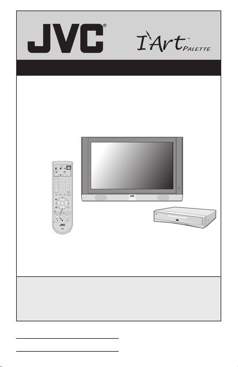
Illustration of PD-42WX84 and RM-C13G
Important Note:
In the spaces below, enter the model and serial number of your television
(located at the rear of the television cabinet). Staple your sales receipt or invoice
to the inside cover of this guide. Keep this user’s guide in a convenient place for
future reference. Keep the carton and original packaging for future use.
Model Number:
Serial Number:
LCT1480-001A
0803-KT-CR-VP
Page 2
Important Safety Precautions
CAUTION
RISK OF ELECTRIC SHOCK
DO NOT OPEN
CAUTION: To reduce the risk of electric shock. Do not
remove cover (or back). No user serviceable
parts inside. Refer servicing to qualified service
personnel.
The lightning flash with arrowhead symbol, within an
equilateral triangle is intended to alert the user to the
presence of uninsulated “dangerous voltage” within
the product’s enclosure that may be of sufficient
magnitude to constitute a risk of electric shock to
persons.
The exclamation point within an equilateral triangle is
intended to alert the user to the presence of important
operating and maintenance (servicing) instructions in
the literature accompanying the appliance.
WARNING: TO PREVENT FIRE OR SHOCK HAZARDS, DO NOT EXPOSE THIS TV SET
TO RAIN OR MOISTURE.
Page 3

CAUTION: TO INSURE PERSONAL SAFETY, OBSERVE THE FOLLOWING RULES
REGARDING THE USE OF THIS UNIT.
1. Operate only from the power source specified on the unit.
2. Avoid damaging the AC plug and power cord.
3. Avoid Improper installation and never position the unit where good
4. Do not allow objects or liquid into the cabinet openings.
5. In the event of trouble, unplug the unit and call a service technician. Do
Changes or modifications not approved by JVC could void the warranty.
* When you don’t use this TV set for a long period of time, be sure to
* To prevent electric shock do not use this polarized plug with an
ventilation is unattainable.
not attempt to repair it yourself or remove the rear cover.
disconnect both the power plug from the AC outlet and antenna for your
safety.
extension cord, receptacle or other outlet unless the blades can be fully
inserted to prevent blade exposure.
• As an “ENERGY STAR®” partner,
JVC has determined that this
product or product model meets the
“ENERGY STAR®” guidelines for energy
efficiency.
Important Safeguards
CAUTION:
Please read and retain for your safety.
Electrical energy can perform many useful functions. This TV set has been engineered and
manufactured to assure your personal safety. But improper use can result in potential
electrical shock or fire hazards. In order not to defeat the safeguards incorporated in this
TV set, observe the following basic rules for its installation, use and servicing. Also follow all
warnings and instructions marked on your TV set.
Page 4

INSTALLATION
1 Operate the TV set only from a power source as indicated on the TV set or refer to the
operating instructions for this information. If you are not sure of the type of power supply to
your home, consult your TV set dealer or local power company. For battery operation, refer
to the operating instructions.
2 Overloaded AC outlets and extension cords are dangerous, and so are frayed power cords
and broken plugs. They may result in a shock or fire hazard. Call your service technician for
replacement.
3 Do not allow anything to rest on or roll over the power cord, and do not place the TV set
where power cord is subject to traffic or abuse. This may result in a shock or fire hazard.
4 Do not use this TV set near water — for example, near a bathtub, washbowl, kitchen sink,
or laundry tub, in a wet basement, or near swimming pool, etc.
5 Avoid improper installation and never position the unit where good ventilation is impossible.
When installing this TV, distance recommendations must be maintained between the set
and the wall, as well as inside a tightly enclosed area or piece of furniture. Keep to the
minimum distance guidelines shown for safe operation.
8 inch/200 mm
6 inch/150 mm
2 inch/50 mm
4 inch/100 mm
6 inch/150 mm
4 inch/100 mm4 inch/100 mm 4 inch/100 mm
2 inch/50 mm
6 Cautions for installation
— Do not tilt the TV towards the left or right, or towards the back.
— Install the TV in a corner on a wall or on the floor so as to keep cords out of the way.
— The TV will generate a slight amount of heat during operation. Ensure that sufficient
space is available around the TV to allow satisfactory cooling.
— The ambient temperature for using this TV is 0˚ to 40˚C (32˚ to 104˚F). Using the TV
outside of this range may lead to it not working correctly or being broken.
7 If an outside antenna is connected to the TV set, be sure the antenna system is grounded
so as to provide some protection against voltage surges and built-up static charges.
Section 810 of the National Electrical Code provides information with respect to proper
grounding of the mast and supporting structure, grounding of the lead-in wire to an
antenna discharge unit, size of grounding conductors, location of antenna discharge unit,
connection requirements for the grounding electrode.
Page 5
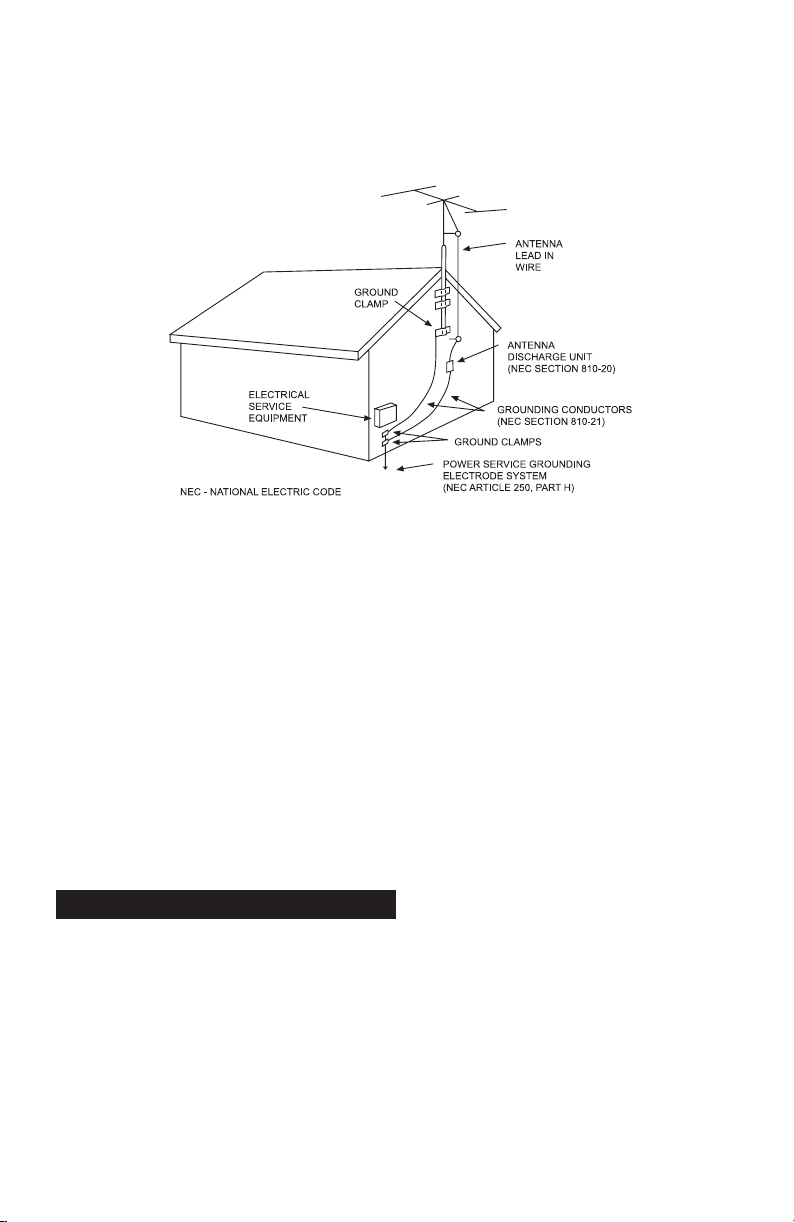
8 An outside antenna system should not be located in the vicinity of overhead power lines or
other electric light or power circuits, or where it can fall into such power lines or circuits.
When installing an outside antenna system, extreme care should be taken to keep from
touching such power lines or circuits as contact with them might be fatal.
EXAMPLE OF ANTENNA GROUNDING
AS PER NATIONAL ELECTRICAL CODE
9 TV sets are provided with ventilation openings in the cabinet to allow heat generated during
operation to be released.
Therefore:
— Never block the bottom ventilation slots of a portable TV set by placing it on a bed,
sofa, rug, etc.
— Never place a TV set in a “built-in” enclosure unless proper ventilation is provided.
— Never cover the openings with a cloth or other material.
— Never place the TV set near or over a radiator or heat register.
10 To avoid personal injury:
— Do not place a TV set on a sloping shelf unless properly secured.
— Use only a cart or stand recommended by the TV set manufacturer.
— Do not try to roll a cart with small casters across thresholds or deep pile carpets.
— Wall or shelf mounting should follow the manufacturer’s instructions, and should use a
mounting kit approved by the manufacturer.
Use
11 Caution children about dropping or pushing objects into the TV set through cabinet
openings. Some internal parts carry hazardous voltages and contact can result in a fire or
electrical shock.
12 Unplug the TV set from the wall outlet before cleaning. Do not use liquid or an aerosol
cleaner.
13 Never add accessories to a TV set that has not been designed for this purpose. Such
additions may result in a hazard.
Page 6

PORTABLE CART WARNING
(Symbol provided by RETAC)
14 For added protection of the TV set during a lightning storm or when the TV set is to be left
unattended for an extended period of time, unplug it from the wall outlet and disconnect
the antenna. This will prevent damage to product due to lightning storms or power line
surges.
15 A TV set and cart combination should be moved with care. Quick stops, excessive force,
and uneven surfaces may cause the TV set and cart combination to overturn.
Service
16 Unplug this TV set from the wall outlet and refer servicing to qualified service personnel
under the following conditions:
A. When the power cord or plug is damaged or frayed.
B. If liquid has been spilled into the TV set.
C. If the TV set has been exposed to rain or water.
D. If the TV set does not operate normally by following the operating instructions.
Adjust only those controls that are covered in the operating instructions as improper
adjustment of other controls may result in damage and will often require extensive
work by a qualified technician to restore the TV set to normal operation.
E. If the TV set has been dropped or damaged in any way.
F. When the TV set exhibits a distinct change in performance — this indicates a need for
service.
17 Do not attempt to service this TV set yourself as opening or removing covers may
expose you to dangerous voltage or other hazards. Refer all servicing to qualified service
personnel.
18 When replacement parts are required, have the service technician verify in writing that the
replacement parts he uses have the same safety characteristics as the original parts. Use
of manufacturer’s specified replacement parts can prevent fire, shock, or other hazards.
19 Upon completion of any service or repairs to this TV set, please ask the service technician
to perform the safety check described in the manufacturer’s service literature.
20 When a TV set reaches the end of its useful life, improper disposal could result in a picture
tube implosion. Ask a qualified service technician to dispose of the TV set.
21 Note to CATV system installer.
This reminder is provided to call the CATV system installer’s attention to Article 820-40 of
the NEC that provides guidelines for proper grounding and, in particular, specifies that the
cable ground shall be connected to the grounding system of the building, as close to the
point of cable entry as practical.
Page 7
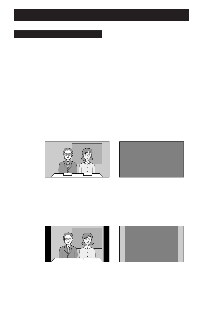
WARNING
Burn-in
A characteristic of Plasma Display Panels (PDPs) is that displaying the same image for a long
time causes a part of the image to stay on the screen (this is called phosphor burn-in).
Avoid burn-in as follows.
IMAGE SHIFT
The picture displayed on the screen is shifted up, down and to the left and right at regular
intervals. In order to prevent burn-in, set this function to FAST or STD. (Refer to page 45.)
Even if the IMAGE SHIFT function is turned off, the picture will shift to the left or right when the
channel or input is changed. This is only when the ASPECT function is in REGULAR mode.
VIDEO STATUS
The VIDEO STATUS function is initially set to DYNAMIC. Unless the TV is being watched in an
extremely bright room, it is recommended to change the VIDEO STATUS setting to standard,
theater or game. Doing so will reduce the chance of PDP burn-in and extend the life of the
PDP. (Refer to page 58).
Do not display static images or characters for long periods of time.
Burn-in example
While an image is displayed With power OFF
19:03
19:03
• Reduce PICTURE and BRIGHT on the PICTURE ADJUST menu (page 49) when viewing.
Do not view for long periods of time in the REGULAR mode (page 60).
Screen size is normally chosen to ensure that the picture is displayed on the entire screen.
After viewing in the REGULAR mode in which black bands may occur at the left and right of
the screen, it is recommended to change to the PANORAMA mode to display the picture on
the entire screen.
While an image is displayed With power OFF
Burn-in example
Do not view for long periods of time using the SPLIT function (page 54) or INDEX
function (page 55).
Page 8

WARNING
If Burn-in has occurred
If burn-in occurs, try the BURN-IN IMAGE REDUCER function (page 50). If burn-in is minimal it
may gradually become less noticeable.
Note: Once burn-in occurs it will never disappear completely.
Point defects
PDPs use collections of fine pixels to display images. While there is no problem with more than
99.99% of these pixels, please understand that a very small number of pixels may not light or
may light all the time.
Do not install the TV near electronic equipment that is susceptible to electromagnetic
waves
It may cause interference in images, sound, etc. In particular, keep video equipment away from
this product.
Effect on infrared devices
There may be interference while using infrared devices such as infrared cordless headphones.
The phenomenon described below is not a malfunction.
If the television is used at a location above an altitude of 2,000 m, a buzzing noise and image
distortion may occur. This phenomenon is peculiar to PDP (Plasma Display Panel), and could
occur with any television using PDP. It is not a malfunction.
Page 9

Table of Contents
Quick Setup . . . . . . . . . 10
Unpacking your TV . . . . . . . . . . . 10
Attaching the stand to the TV . . . . . . 11
TV/Receiver . . . . . . . . . . . . . . . 12
TV Remote Control . . . . . . . . . . . 13
Getting Started . . . . . . . . . . . . . 14
Set Up Your TV . . . . . . . . . . . . 14
The Remote Control . . . . . . . . . . 16
Connections . . . . . . . . . . . . . . . 18
Connecting Your Devices . . . . . . . 18
Plug-In Menu . . . . . . . . . . . . . . 25
The Interactive Plug In Menu . . . . . 25
Remote Programming . . . . 28
Setting CATV, VCR and DVD Codes . . 28
Cable box or Satellite Codes . . . . . 28
VCR Codes . . . . . . . . . . . . . . 29
DVD Codes . . . . . . . . . . . . . . 30
Search Codes . . . . . . . . . . . . . 31
Onscreen Menus . . . . . . 32
Using the Guide . . . . . . . . . . . . . 32
The Onscreen Menu System . . . . . . 33
Initial Setup . . . . . . . . . 35
Auto Tuner Setup . . . . . . . . . . . . 35
Channel Summary . . . . . . . . . . . . 35
V-Chip . . . . . . . . . . . . . . . . . . 36
Set Lock Code . . . . . . . . . . . . . 42
Auto Demo . . . . . . . . . . . . . . . 43
Power Indicator . . . . . . . . . . . . . 43
Position Adjustment . . . . . . . . . . . 43
Digital-In . . . . . . . . . . . . . . . . . 44
TV Speaker . . . . . . . . . . . . . . . 44
Audio Out . . . . . . . . . . . . . . . . 45
Image Shift . . . . . . . . . . . . . . . 45
Language . . . . . . . . . . . . . . . . 45
Closed Caption . . . . . . . . . . . . . 46
Noise Muting . . . . . . . . . . . . . . 46
Front Panel Lock . . . . . . . . . . . . 47
V1 Smart Input . . . . . . . . . . . . . 47
Auto Shut Off . . . . . . . . . . . . . . 48
XDS ID . . . . . . . . . . . . . . . . . . 48
Picture Adjust . . . . . . . . 49
Picture Settings . . . . . . . . . . . . . 49
Adjust Picture Settings . . . . . . . . 49
Color Temperature . . . . . . . . . . . . 49
Digital Noise Clear . . . . . . . . . . . . 50
Color Management . . . . . . . . . . . 50
Burn-in Image Reducer . . . . . . . . . 50
Reset . . . . . . . . . . . . . . . . . . 50
Sound Adjust . . . . . . . . 51
Sound Settings . . . . . . . . . . . . . 51
Adjust Sound Settings . . . . . . . . 51
MTS (Multi-Channel Television Sound) . 51
Clock/Timers . . . . . . . . 52
Set Clock . . . . . . . . . . . . . . . . 52
On/Off Timer . . . . . . . . . . . . . . . 53
Button Functions . . . . . . 54
Multi Screen Function . . . . . . . . . . 54
Split . . . . . . . . . . . . . . . . . . . 54
Index . . . . . . . . . . . . . . . . . . . 55
Freeze . . . . . . . . . . . . . . . . . . 55
Swap . . . . . . . . . . . . . . . . . . 55
Select . . . . . . . . . . . . . . . . . . 55
Power . . . . . . . . . . . . . . . . . . 56
Number Buttons . . . . . . . . . . . . . 56
100+ Button . . . . . . . . . . . . . . . 56
Input . . . . . . . . . . . . . . . . . . . 56
Digital-In . . . . . . . . . . . . . . . . . 56
Return +/TV . . . . . . . . . . . . . . . 57
Sound . . . . . . . . . . . . . . . . . . 57
Muting . . . . . . . . . . . . . . . . . . 58
Video Status . . . . . . . . . . . . . . . 58
Natural Cinema . . . . . . . . . . . . . 58
TheaterPro D6500K . . . . . . . . . . . 58
Sleep Timer . . . . . . . . . . . . . . . 59
Display . . . . . . . . . . . . . . . . . . 59
Aspect . . . . . . . . . . . . . . . . . . 60
Aspect Ratios . . . . . . . . . . . . . 60
C.C. . . . . . . . . . . . . . . . . . . . 61
Menu . . . . . . . . . . . . . . . . . . 61
OK . . . . . . . . . . . . . . . . . . . . 61
Back . . . . . . . . . . . . . . . . . . . 61
TV/CATV Slide Switch . . . . . . . . . . 62
VCR/DVD Slide Switch . . . . . . . . . 62
VCR Buttons . . . . . . . . . . . . . . . 62
DVD Buttons . . . . . . . . . . . . . . . 62
Light . . . . . . . . . . . . . . . . . . . 62
Appendices
Troubleshooting . . . . . . . . . . . . . 65
Warnings . . . . . . . . . . . . . . . . 65
Warranty . . . . . . . . . . . . . . . . . 66
9
Authorized Service Centers . . . . . . . 68
Specifications . . . . . . . . . . . . . . 69
Page 10
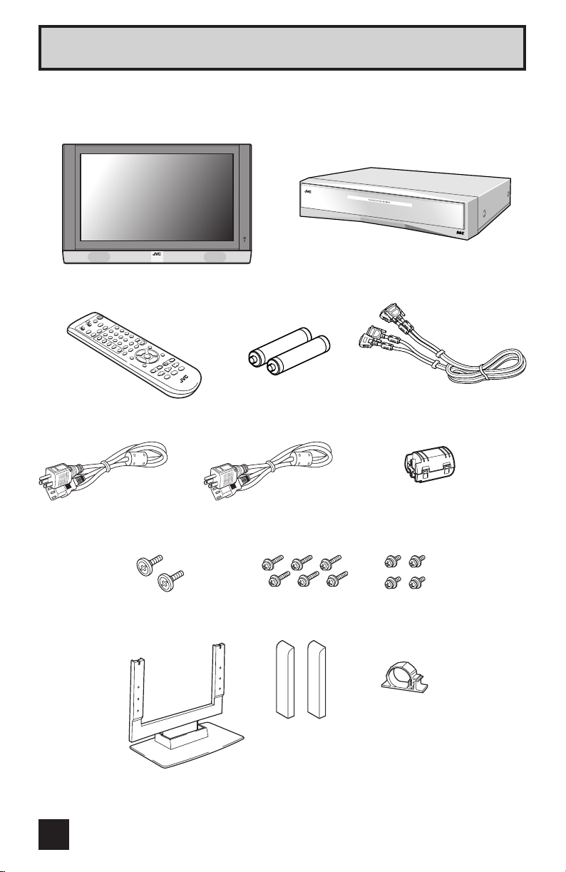
Quick Setup Unpacking your TV
Thank you for your purchase of a JVC Color Television. Before you begin setting up your new
television, please check to make sure you have all of the following items.
Receiver
TV
Remote control
Power cord
Screw (A) × 2
Stand × 1
AA/R06-size batteries
(used to check operation)
Screw (B) × 6
Cover × 2
System cable
Ferrite core × 1
Screw (C) × 4
Cable clamp × 1
10
Page 11
Quick Setup Attaching the stand to the TV
Read the following instructions and then attach the supplied stand to the TV.
WARNING: The TV is heavy. It should always be carried by at least two people.
Attempting to carry it by yourself may lead to it being dropped causing
injuries and damage.
Required items: Phillips screwdriver
1. Attach the screws (A) to the back of the TV.
2. Attach the TV to the stand.
Insert the heads of the screws (A) into the top
of the stand bar and temporarily secure the TV
to the stand.
3. Secure the TV to the stand with the screws (B).
Screw (A)
Screw (B)Screw (B)
Stand
4. Insert the cover to the stand and fix with the
screws (C).
5. Remove the paper from the bottom of the cable
clamp and attach the cable clamp to the stand.
• Clamp the system cable and power cord using the
cable clamp after connecting the system cable and
the power cord to the TV.
Cover
Screw (C)
Cable clamp
11
Page 12
Quick Setup TV/Receiver
NOTE: Before you connect your receiver to another device, please refer to the proper
diagrams for your specific TV and remote.
Display Front
Refer to the pages in parentheses for details.
1 Remote control sensor
2 Power lamp (page 17)
3 MENU button (pages 34)
4 INPUT button (page 56)
5 VOL (Volume) -/+ buttons
6 CH -/+ buttons (page 16)
7 POWER button
Receiver Front
Refer to the pages in parentheses for details.
12
How to open the cover
S-VIDEO
AUDIO
VIDEO
POWER
R
L/MONO
OVER
INPUT-4
1 INPUT-4 terminal (pages 22)
2 POWER button (page 17)
3 Power lamp (page 17)
Page 13
Quick Setup TV Remote Control
TV
CATV VCR DVD
SPLIT
FREEZE
INPUT 1
V1
INPUT 2
V2
INPUT 3
V3
INPUT 4
V4
DIGITAL-IN
D-IN
SLEEP TIMER
MUTING
MENU
VCR CHANNEL
PREV NEXT
REW
OPEN CLOSE
ASPECT
MULTI SCREEN
INDEX
SWAP SELECT
123
456
789
100+
0
THEATER
NATURAL
PRO
CINEMA
DISPLAY SOUND
+
CH
VOL
REC PAUSE
OK
CH
VCR DVD
STOP
VOL
POWER
STILL PAUSE
RETURN+
TV
VIDEO
STATUS
LIGHT
C.C.
C.C.
BACK
TV VCR
FFPLAY
RM-C13G
RM-C13G
• For information on remote control buttons, see pages 54-62.
13
Page 14
Quick Setup Getting Started
Getting Started
These quick setup pages will provide you, in four easy steps, with the basic information you
need to begin using your new television right away.
If you have questions, or for more detailed information on any of these steps, please consult
other sections of this manual.
STEP 1 - Set Up Your TV
Caution
• Turn off all equipment (including the TV) before connecting anything.
Connection Diagram
TV (back)
DISPLAY INPUT
CONNECT TO SYSTEM CABLE
Supplied system cable
• Refer to page 15 for
connection details.
SUB
AUDIO OUT
WOOFER
OUT
AV
COMPULINK
14
R-AUDIO-L VIDEO
DIGITAL IN
P
b
DISPLAY OUT(SYSTEM CABLE)
PrPbPr
Receiver (back)
AC 120V
Cable supplied
with TV
• Refer to page 15
for connection
details.
Cable supplied with receiver
• Refer to page 15 for connection details.
Page 15
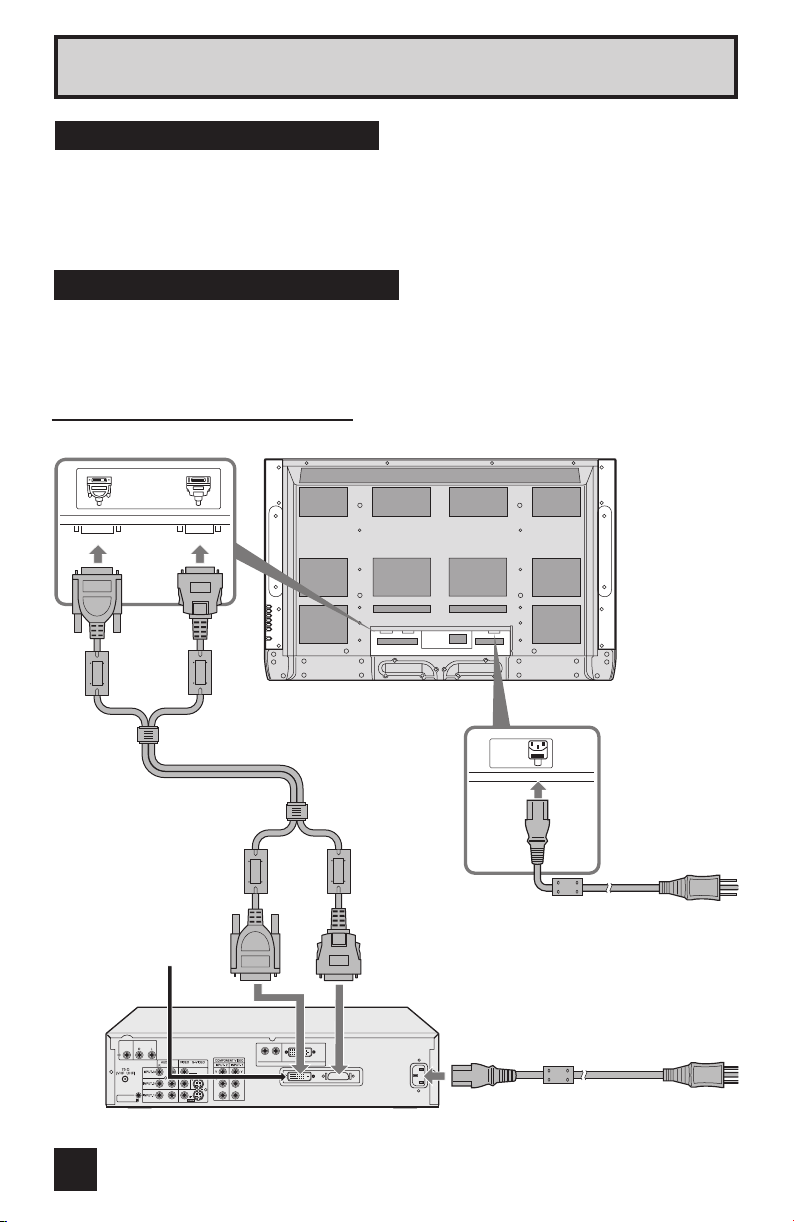
Quick Setup Getting Started
Connecting the TV and
receiver
Use the supplied system cable to connect
the TV to the receiver.
The two connectors are of different shapes.
Ensure that the pins on connector 1 are
oriented correctly, press the connector into
the socket, and tighten the screws at left
and right to lock it in place.
Press connector 2 firmly into place until it
is locked.
1
2
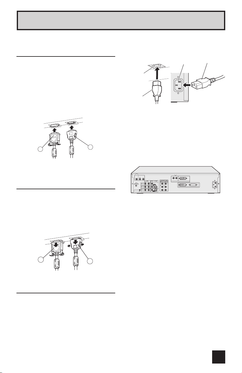
Disconnecting the system
cable
Release connector 1 by unscrewing the
screws at left and right and removing it from
the socket.
Release connector 2 by removing it from
the socket while pressing the release
bottoms on either side.
Use the supplied power cord which best
suits the area in which you live.
Back of the TV
AC INLET
Power cord
AC INLET
Back of the receiver
Power cord
Insert the AC plug into a correctly grounded
outlet.
• Remove the AC plug from the outlet to
completely disconnect the TV from the
power supply.
Receiver rear
SUB
AUDIO OUT
WOOFER
OUT
AV
COMPULINK
R-AUDIO-L VIDEO
DIGITAL IN
PbPrPb
Pr
DISPLAY OUT(SYSTEM CABLE)
1
2
Connecting the power cord
to the AC outlet
Insert the AC plugs on the power cords from
the TV and receiver into AC outlets.
Caution
• Operate only from the power source
specified (AC 120V, 60 Hz) on the unit.
• Failure to use the supplied power cord or
to insert it into a correctly grounded outlet
may result in electric shocks.
15
Page 16

Quick Setup Getting Started
Step 2 – The Remote Control
Before you can operate your remote
control, you first need to install the
batteries (included).
Slide the cover on the back of the
remote down towards the bottom of
the remote control. Insert two batteries
(included) carefully noting the “+” and
“–” markings, placing the “–” end in
the unit first. Slide the cover back into
place.
When you change the batteries, try to complete the task within three minutes. If you
take longer than three minutes, the remote control codes for your VCR, DVD, and/or
cable box/satellite receiver may have to be reset. See pages 28 - 31.
Key Feature Buttons
The four key feature buttons at the center of the remote
can be used for basic operation of the television. The top
and bottom buttons will scan forward and back through
the available channels. To move rapidly through the
channels using JVC’s Hyperscan feature, press and hold
CH+ or CH –. The channels will zip by at a rate of five
channels per second. The right and left buttons will turn
the volume up or down. These buttons are also marked
with four arrows and are used with JVC’s onscreen menu
system. To use the onscreen menus, press the M
button.
ENU
16
Page 17
Quick Setup Getting Started
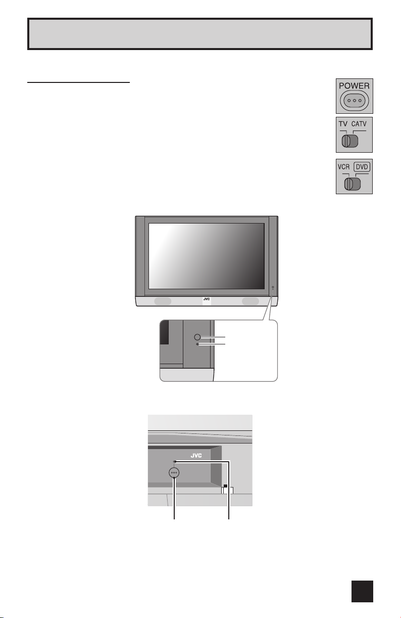
Basic Operation
Turn the television on and off by pressing the POWER button at the top right
corner of the remote. If this is the first time you are turning on the TV, the
interactive plug-in menu appears.
• Turn on the TV after connecting it to the other surrounding devices. (Refer to
page 18.)
• Make sure the TV/CATV switch is set to TV. Move the switch to CATV only if
you need to operate a cable box.
• Slide the VCR/DVD selector switch to VCR to control a VCR. Slide to
DVD to control a DVD player. Please see pages 28 to 31 for instructions on
programming your remote control to operate a cable box, VCR or DVD player.
Display front
Remote control
sensor
Power lamp
Receiver front
POWER
• When the TV is off, the TV and TUNER power lamps do not light. When the TV is on, the
TV and TUNER power lamps light. However, when the POWER INDICATOR in the MENU
is set to OFF, the power lamps do not light even when the TV is on. (Refer to “POWER
INDICATOR” on page 43)
Power lampPOWER button
17
Page 18
Quick Setup Connections
Step 3 – Connecting Your Devices
To make these connections, you will use plugs like the ones illustrated below.
Coaxial Cables
Ferrite core (accessory)
Component Cables
Composite Cables
Audio Cables
Used to connect audio/video
Used to connect an external
antenna or cable TV system
to your receiver.
Attach the ferrite core to the coaxial cable. Using
it without the ferrite core may lead to noise
(interference).
• Attach the ferrite core as close to the receiver
as possible.
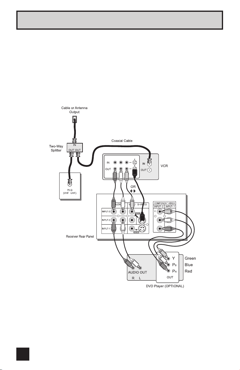
Please follow the flow chart below to determine which connection setup is right for you. Then,
refer to the appropriate diagrams to connect your receiver to other devices that you may have.
After you are finished connecting your devices, plug the power cord into the nearest power
outlet and turn on the TV.
A VCR is not necessary for operation of the television. If you follow these diagrams and the
television does not work properly, contact your local cable operator.
• To connect a DVD player, see Diagram #3. A DVD player is optional.
• If you have a satellite television system, please refer to the satellite TV manual.
devices like VCRs, DVD
players, stereo amplifiers, game
consoles, etc.
S-Video Cable
Used to make video connections
with S-Video VCRs, Camcorders
and DVD players.
18
Do you use a Cable TV Box?
Yes
Do you have a VCR? Do you have a VCR?
Yes No Yes No
Diagram #2
Diagram #1 Diagram #3 Diagram #1
No
Page 19

Quick Setup Connections
Diagram #1
Note:
• If you do not have a cable box, connect the cable wire from the wall outlet into the back of
the receiver.
Diagram #2
Notes:
• Use the S-Video connection if possible for superior picture quality.
• Your VCR must be turned on to view premium cable channels.
19
Page 20
Quick Setup Connections
Notes:
• Green, blue and red are the most common colors for DVD cables. Some models may vary
colors. Please consult the user’s manual for your DVD player for more information.
• Be careful not to confuse the red DVD cable with the red audio cable. It is best to complete
one set of connections (DVD or audio output) before starting the other to avoid accidentally
switching the cables.
• You may also connect the DVD player to Input 1.
Diagram #3
20
Pb
Pr
Pb
Pr
Page 21
Quick Setup Connections
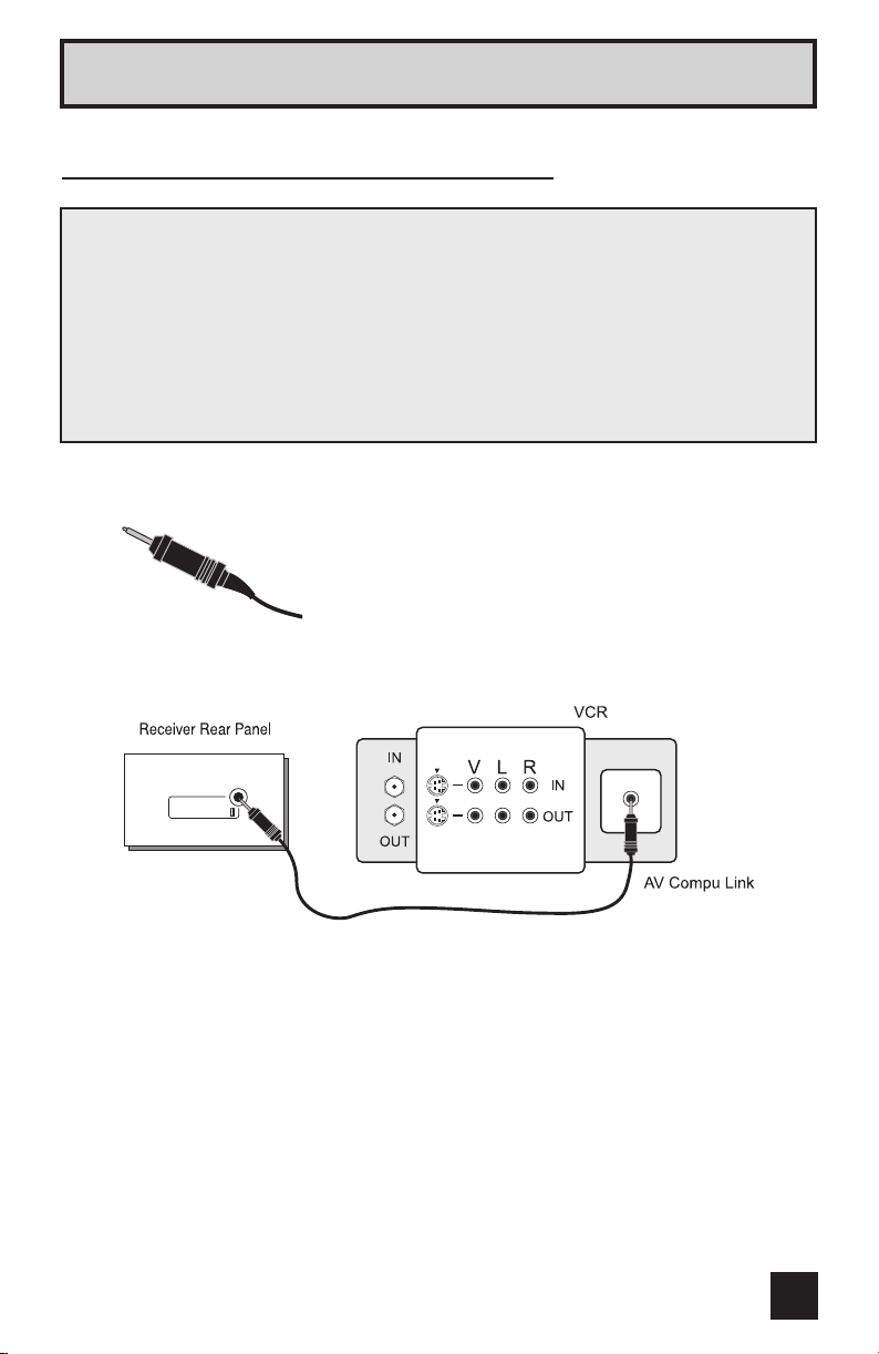
Connecting to JVC AV Compu Link
JVC’s AV compu link feature makes playing video tapes or DVDs totally automatic. Simply
insert a pre-recorded tape into your JVC brand VCR or DVD into your JVC DVD player
and the device will automatically turn on and begin playback. At the same time, using the
AV compu link, the VCR or DVD player sends a signal to the television telling it to turn on
and switch to the proper video input.
• The AV compu link cable may be included with the JVC AV compu link unit you
wish to connect. If it is not, contact JVC Parts Department at (800)-882-2345, or
www.jvcservice.com for part # EWP 805-012.
• AV Compu Link can only be used with JVC brand products.
AV Compu Link Cable
AV
COMPULINK
Notes:
• In order for the VCR playback to begin automatically, the recording tabs must be removed
from the VHS tape. If the tab is in place, automatic switching will occur when you push the
LAY button.
VCR’s P
• If your JVC brand VCR has “A code/B code remote control switching” (see your VCR’s
instruction book), using VCR A code will switch the TV to input 1.
• Refer to your DVD instruction book for detailed connection information.
• To connect a JVC HiFi receiver or amplifier for a completely automated home theater, see
the receiver connection instructions for detailed connection information.
• AV compu link is compatible with select AV compu link receivers.
To Connect: Plug one end of the AV compu link cable
into the AV COMPU LINK INPUT on your VCR, DVD, or
other compu link device. Plug the other end of the AV
compu link cable into the AV COMPU LINK at the rear
of the receiver.
Note:
• The AV compu link cable has a male 3.5 mm (mono)
plug on each end.
21
Page 22
Quick Setup Connections
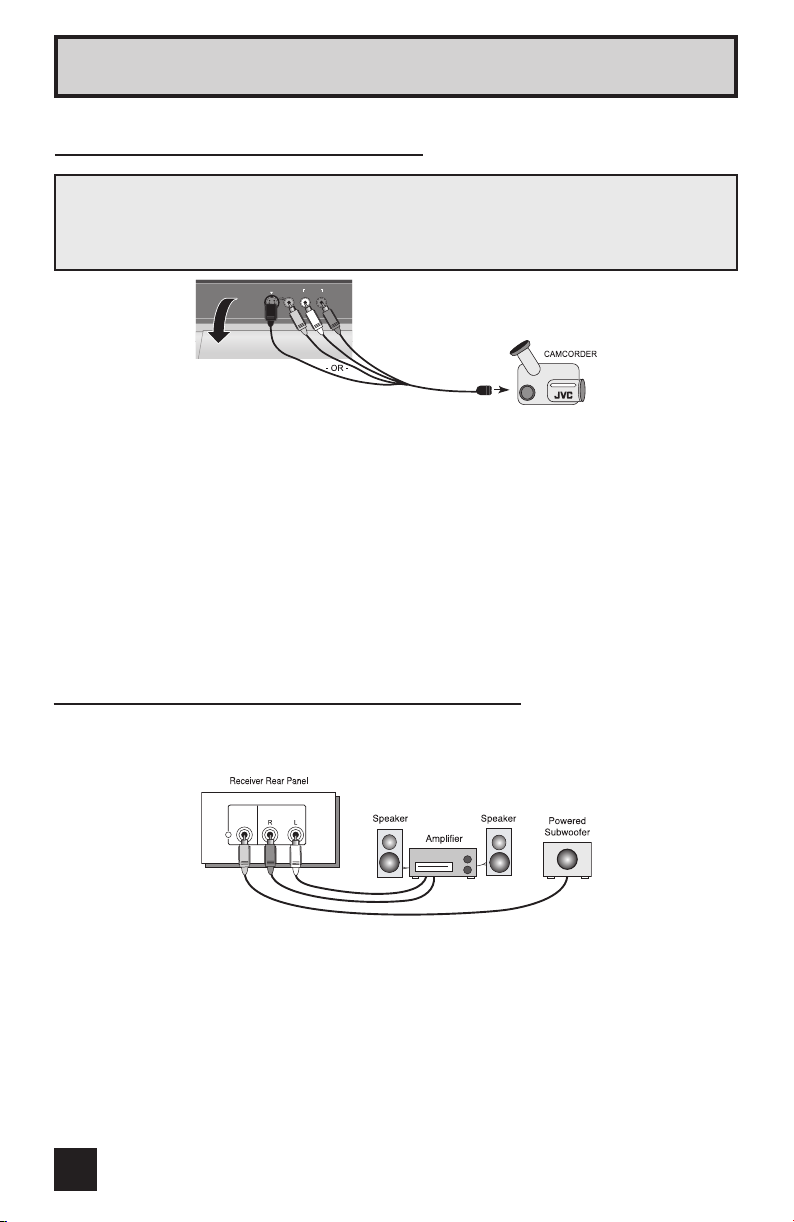
Connecting to a Camcorder
You may connect a camcorder, game console or other equipment to your television by using
the front input jacks (Input 4) located under the front panel door. To access, pull on the door
to open it. You can also connect these using the television’s rear input jacks, using the same
instructions.
S-VIDEO
AUDIO
VIDEO
R
L/MONO
OVER
INPUT-4
1) Connect a yellow composite cable from the camcorder VIDEO OUT, into the VIDEO IN on
the front of the receiver, OR connect an S-Video cable from the front of the receiver to the
camcorder.
2) Connect a white composite cable from the camcorder LEFT AUDIO OUT, into the
LEFT AUDIO IN on the front of the receiver.
3) Connect a red composite cable from the camcorder RIGHT AUDIO OUT, into the
RIGHT AUDIO IN on the front of the receiver.
Note:
• If your camcorder is a mono sound model it will have only one AUDIO OUT. Connect it to
the LEFT AUDIO IN on the front of the receiver.
Connecting to an External Amplifier
Subwoofer Out - Use a powered subwoofer with the surround feature to simulate a home
theater system. Simply connect the subwoofer to the back of the receiver.
SUB
AUDIO OUT
WOOFER
OUT
1) Connect a white composite cable from the LEFT AUDIO OUTPUT on the back of the
receiver to the LEFT AUDIO INPUT on the amplifier.
2) Connect a red composite cable from the RIGHT AUDIO OUTPUT on the back of the
receiver to the RIGHT AUDIO INPUT on the amplifier.
3) Connect a black composite cable from the SUBWOOFER OUT on the back of the receiver
to the LINE INPUT of the subwoofer.
Notes:
• Refer to your amplifier’s manual for more information.
• You can use AUDIO OUTPUT for your home theater system.
22
Page 23

Quick Setup Connections
Connecting to a Digital TV Receiver w/HDCP
By inputting a high bandwidth digital content protection high definition picture source to the
digital-in terminal of this television, high-definition pictures can be displayed on the screen in
their digital form. (This terminal is for use in the future when high bandwidth digital content
protection DTV decoders and DVD players and D-VHS are put on the market.)
After the connections
have been made,
tighten the screw to
secure the cables.
R-AUDIO-L VIDEO
1) Connect the DTV DIGITAL RGB OUTPUT TERMINAL to the DIGITAL INPUT TERMINAL of
the receiver, and then tighten the 2 screws.
2) Connect the DTV decoder LEFT AUDIO OUTPUT to the DIGITAL-IN LEFT AUDIO INPUT.
3) Connect the DTV decoder RIGHT AUDIO OUTPUT to the DIGITAL-IN RIGHT AUDIO
INPUT.
• The Digital-In terminal can only be used with 1080i, 720p and 480p picture signals. Set
the DTV decode digital-out terminal output setting to 1080i, 720p or 480p. For detailed
information, refer to the DTV decoder instruction manual. If you can not display the picture
because your DTV decoder does not have a digital-out terminal output setting, use the
component video input (or the S-Video input or video input). Refer to page 20. In this case
the picture will be displayed as an analog signal.
• The digital-in terminal is not compatible with the picture signal of a personal computer.
• Use a DVI-D single link 19-pin cable (commercially available) in order to digitally connect
the receiver with a DTV decoder.
If 480p signals (640x480 or 720x480) are displayed on the screen, the horizontal balance may
be slightly shifted. In cases such as this, the horizontal balance can be adjusted by accessing
“DIGITAL-IN” in the INITIAL SETUP menu. (Refer to page 44.)
DIGITAL IN
DTV decoder
23
Page 24

Quick Setup Connections
Connecting to an AV Receiver using your television’s
V1 Smart Input
By connecting your AV Receiver to your television's V1 smart Input, you can watch picture
sources from many diffeent devices, without having to change or use the other input
connections on your TV. This allows you to free up other input connections so you can
connect more devices to your television.
AV Receiver
MONITOR
OUT
Y
B
P
P
R
MONITOR OUT
Receiver Rear Panel
Pb
Pr
Pb
Pr
1) Connect an S-Video Cable from the AV Receiver's MONITOR OUT, to the S-Video INPUT-1
on the back of your receiver.
2) Connect a Yellow Component Cable from the AV Receiver's MONITOR OUT, into the
VIDEO INPUT-1 on the back of your receiver.
3) Connect a Green Component Cable from the AV Receiver's Y MONITOR OUT, into the Y
VIDEO INPUT-1 on the back of your receiver.
4) Connect a Blue Component Cable from the AV Receiver's P
B MONITOR OUT, into the PB
VIDEO INPUT-1 on the back of your receiver.
5) Connect a Red Component Cable from the AV Receiver's PR MONITOR OUT, into the PR
VIDEO INPUT-1 on the back of your receiver.
Notes:
• Please refer to your AV Receiver instruction manual for more information on connecting
your speakers and other devices like a DVD player.
• Use your AV Receiver's remote to switch to the diferent devices you have connected.
• Some AV Receiver's may not respond when the V1 Smart Input funcion is turned on.
• If you have video connections for each input device connected to your AV Receiver, you
should not connect them using both S-Video and Composite connection at the same time
when you are using V1 input as the V1 Smart Input. In this case we recommend using the
S-Video connection.
24
Page 25

Quick Setup Plug-In Menu
Step 4 – The Interactive Plug In Menu
When you turn your television on for the first time the interactive plug-in menu will appear.
The plug-in menu helps you to get your TV ready to use by letting you set your preferences
for:
• The language in which you want the onscreen menus to appear.
• Setting the TV’s clock to the correct time so your timer functions will work properly. You can
choose “AUTO” or “MANUAL” for setting the clock.
• The auto tuner setup of which channels you wish to receive.
We recommend you complete the interactive plug-in items before you start using your
television.
Language
After the “JVC INTERACTIVE PLUG IN MENU” has been displayed, the TV automatically
switches to the LANGUAGE settings. You can choose to view your onscreen menus in three
languages: English, French (Français) or Spanish (Español).
¥
To choose a language:
(English, Français or Español)
To NEXT (To set clock)
(To be continued...)
25
Page 26
Quick Setup Plug-In Menu
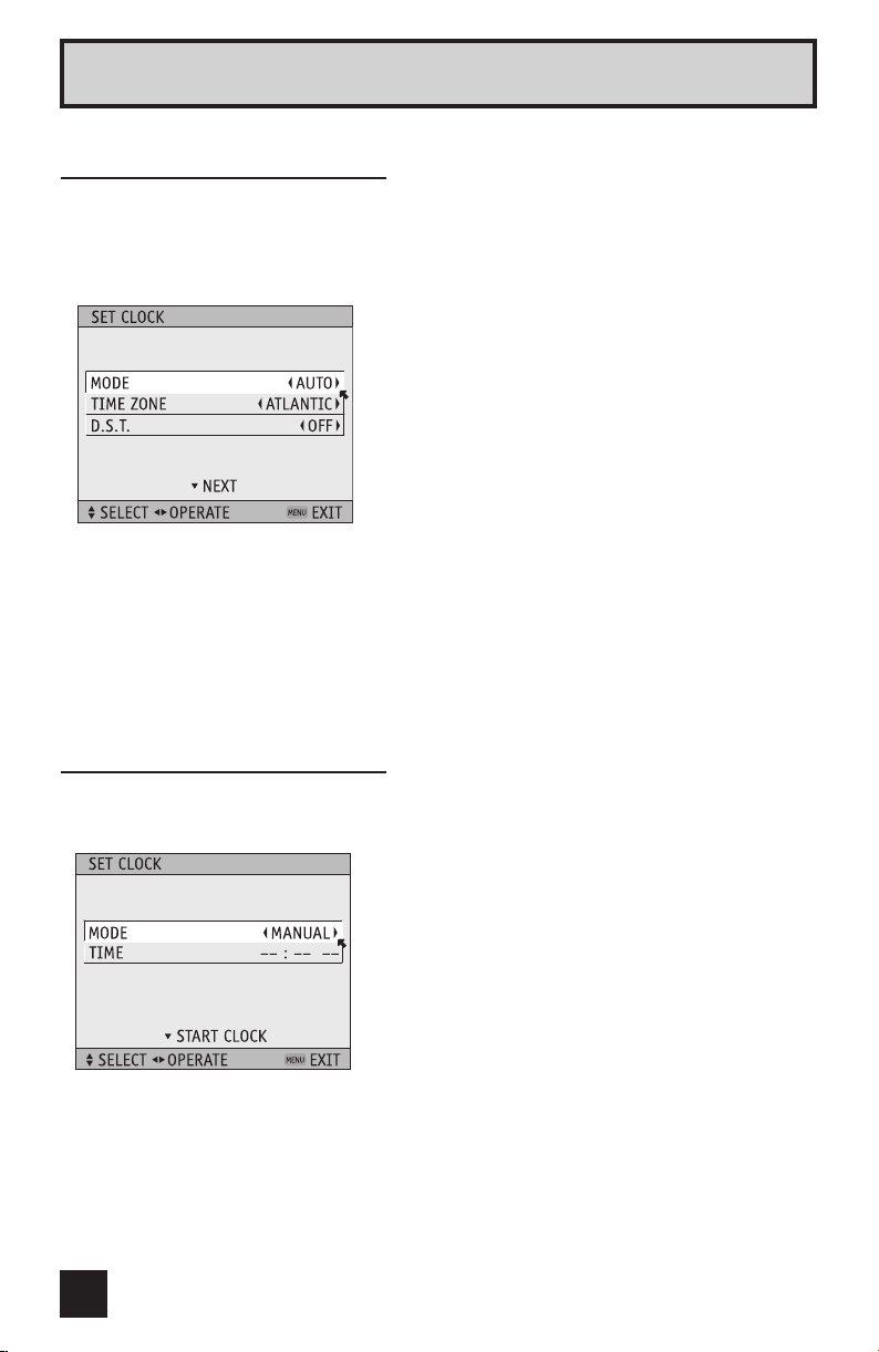
Auto Clock Set
Before you use any of your TV’s timer functions, you must first set the clock. You
may precisely set your clock using the XDS time signal broadcast by most public
broadcasting stations. If you do not have this in your area, you will have to set the clock
manually. See manual clock set below. To set the clock using the XDS signal:
¥
To choose AUTO
To TIME ZONE
¥
To select your time zone: (Atlantic, Eastern,
Central, Mountain, Pacific, Alaska or
Hawaii)
To move to D.S.T. (Daylight Savings Time)
¥
To turn D.S.T. ON or OFF
To NEXT (To Auto Tuner Setup)
Notes:
• The Daylight Savings Time feature automatically adjusts your TV’s clock for Daylight
Savings. The clock will move forward one hour at 2:00 am on the first Sunday in April. The
clock will move back one hour at 2:00 am on the last Sunday in October.
• You will have to reset the clock after a power interruption. You must set the clock before
operating any timer functions.
Manual Clock Set
To set your clock manually (without using the XDS signal), choose MANUAL. If you choose
AUTO, see auto clock set above.
¥
To choose MANUAL
¥
¥
Note:
• You will have to reset the clock after a power interruption. You must set the clock before
operating any timer functions.
To TIME
To set the hour
To minute
To set the minute
To Start Clock
(To be continued...)
26
Page 27
Quick Setup Plug-In Menu
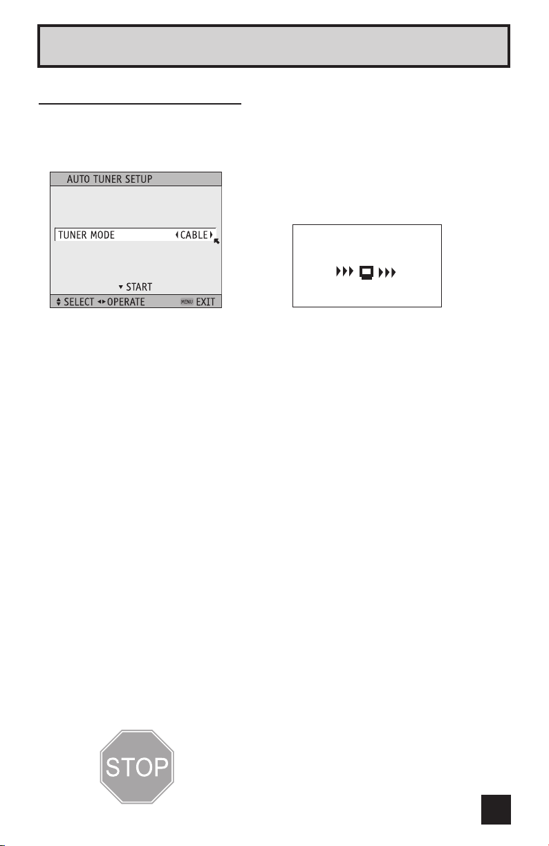
Auto Tuner Setup
In auto tuner setup, the TV automatically scans through all available channels, memorizing the
active ones and skipping over blank ones or channels with weak signals. This means when
you scan (using the C
HANNEL +/– buttons) you will receive only clear, active channels.
¥
skip Auto Tuner Setup)
To choose CABLE or AIR (or SKIP when you
To START
NOW
PROGRAMMING !
48
Programming will take approximately
When the setup is finished, THANK YOU!! SETUP IS NOW COMPLETE is displayed. Your
quick setup is now complete. You can now begin watching your television, or you can
continue on in this guide for more information on programming your remote control, or using
the JVC onscreen menu system to customize your television viewing experience.
Notes:
• Noise muting will not work during Auto Tuner Setup.
• Skip appears only for interactive plug-in menu.
• The interactive plug-in menu setting does not appear if your TV has been turned on before.
In this case, use the menu to perform these settings. See pages 45, 52 and 35.
Cable Box and Satellite Users: After your auto tuner setup is complete, you may,
(depending on the type of hookup), have only 1 channel, usually 3 or 4 in the auto tuner
memory. This is normal.
1 to 2 minutes.
The Quick Setup is complete
27
Page 28

Remote Programming
Setting the CATV, VCR and DVD Codes
You can program your remote to operate your cable box, satellite receiver, VCR or DVD
player by using the instructions and codes listed below. If the equipment does not respond
to any of the codes listed below or to the code search function, use the remote control
supplied by the manufacturer.
Cable Box or Satellite Codes
The remote control is programmed with cable box and satellite codes for power on/off,
channel up/down, and 10 key operation.
1) Find the cable box or satellite brand from the list of codes shown below.
2) Slide the 2-way selector switch to “CATV”.
3) Press and hold down the DISPLAY button, then enter the first code number listed with the
10 key pad.
4) Release the DISPLAY button, and confirm the operation of the cable box/satellite receiver.
• If your cable or satellite box does not respond to the first code, try the others listed. If it
does not respond to any code, try the search codes function, on page 31.
28
Page 29
Remote Programming
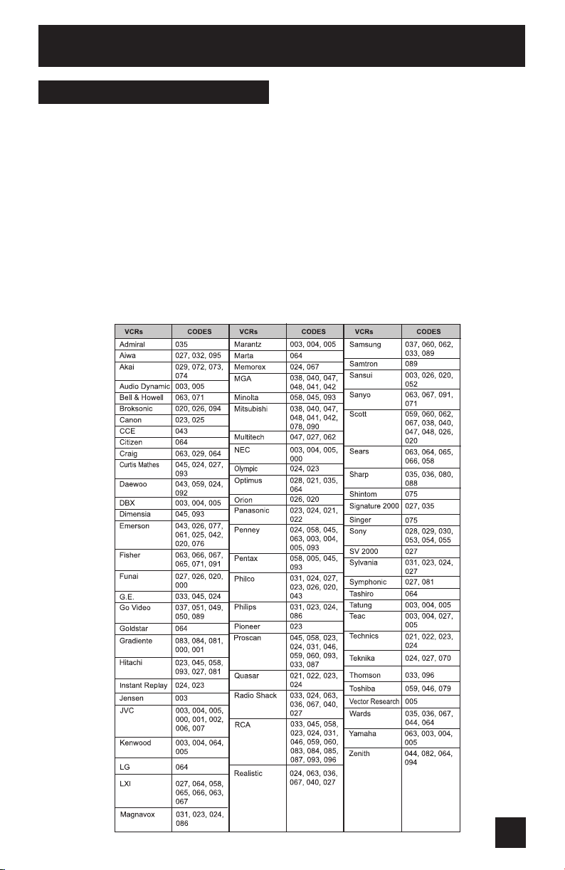
VCR Codes
The remote control is programmed with VCR codes for power on/off, play, stop, fast-forward,
rewind, pause, record, channel up/down operation.
1) Find the VCR brand from the list of codes shown below.
2) Slide the first 2-way selector switch to “TV” and the other 2-way selector switch to “VCR”.
3) Press and hold down the D
10 key pad.
4) Release the DISPLAY button, and confirm the operation of the VCR.
• If your VCR does not respond to the first code, try the others listed. If it does not respond
to any of the codes, try the search codes function on page 31.
• After you program your remote, some VCR buttons may not work properly. If so, use the
VCR’s remote.
• To record, hold down the R
ISPLAY button, then enter the first code number listed with the
EC button on the remote and press PLAY.
29
Page 30
Remote Programming
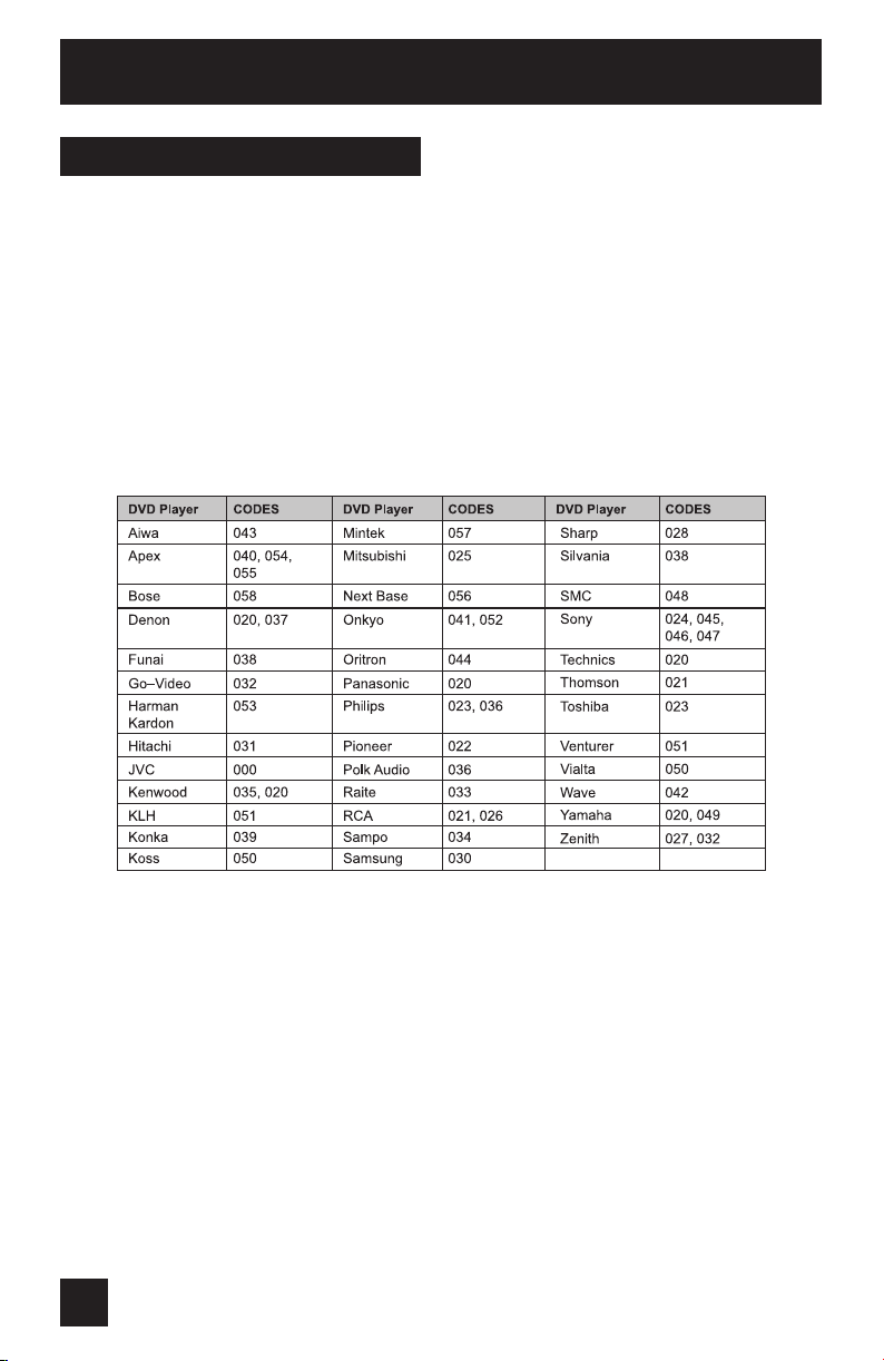
DVD Codes
The remote control is programmed with DVD codes for power on/off, play, stop, fast-forward,
rewind, previous/next chapter, tray open/close, and still/pause operation.
1) Find the DVD player brand from the list of codes shown below.
2) Slide the first 2-way selector switch to “TV” and the other 2-way selector switch to “DVD”.
3) Press and hold down the D
10 key pad.
4) Release the D
• If your DVD player does not respond to the first code, try the others listed. If it does not
respond to any of the codes, try the search codes function on page 31.
• After you program your remote, some DVD buttons may not work properly. If so, use the
DVD player’s remote.
ISPLAY button, and confirm the operation of the DVD player.
ISPLAY button, then enter the first code number listed with the
30
Page 31

Remote Programming
Search Codes
Cable/Satellite Search Codes Function
1) Slide the first 2-Way Mode Selector switch to CATV.
2) Press and hold down the POWER button, then press the RETURN+/TV button for more than
three seconds.
3) Release the RETURN+/TV button, then release the POWER button.
4) Press the POWER button on the remote, and see if the cable or satellite box responds.
5) If there was a response, press RETURN+/TV. The codes are now set. If there was no
response, repeat Step 4. If you repeat Step 4 a total of 80 times without a response, use
the remote control that came with your equipment.
6) Press RETURN+/TV to exit.
VCR/DVD Search Codes Function
1) Slide the first 2-way selector switch to “TV” and the other 2-way selector switch to “VCR”
or “DVD”.
2) Press and hold down the VCR or DVD P
more than three seconds.
3) Release the RETURN+/TV button, then release the VCR or DVD POWER button.
4) Press the VCR or DVD POWER button, and see if the VCR or DVD responds.
5) If there was a response, press RETURN+/TV. The codes are now set. If there was no
response, repeat Step 4. If you repeat Step 4 a total of 80 times for the VCR (40 times for
the DVD player), and there is no response, use the remote control that came with your
equipment.
6) Press R
ETURN+/TV to exit.
OWER button, then press the RETURN+/TV button for
31
Page 32

Onscreen Menus
Using the Guide
Certain symbols are used throughout this guide to help you learn about the features of your
new television. The ones you will see most frequently are:
Up and Down arrows mean press the CH+ or CH– buttons. Pressing the CH+ or CH–
buttons let you:
• Move vertically in a main menu screen
• Move through a submenu screen
• Move to the next letter, number, or other choice in a submenu
• Back up to correct an error
• Scan through TV channels (when not in a menu screen)
¥
Left and right arrows mean press the VOLUME+ or VOLUME– buttons to move left or right
to:
• Select a highlighted menu item
• Select an item in a submenu
• Select numbers in certain menu options
• Turn the volume up or down (when not in a menu screen)
The “press button” icon means you should press the button named on your remote
control. (Button names appear in SMALL CAPITAL LETTERS.)
The “helping arrow” icon points to the highlighted or selected item in a menu.
To bring up the onscreen menu, press the MENU button on the remote control. The item that
appears in green is the one currently selected. If you use the Menu button on the TV’s front
panel instead of the remote, an additional menu screen showing INPUT and ASPECT will
appear between INITIAL SETUP and PICTURE ADJUST. The “interactive plug-in menu” will
appear the first time the TV is plugged in.
Note:
• Menus shown in this book are illustrations, not exact replications of the television’s
onscreen displays.
32
Page 33

Onscreen Menus
The Onscreen Menu System
Your television comes with JVC’s onscreen menu system. The onscreen menus let you make
adjustments to your television’s operation simply and quickly. Examples of the onscreen
menus are shown on the next page. Detailed explanations on using each menu follow later in
this guide. For information about the interactive plug-in Menu, see pages 25 - 27.
The Onscreen Menu System
To open the onscreen menu system, press the MENU button on the remote control. You
navigate within the onscreen menus by using the four directional arrow buttons on the
remote control. (These buttons are also the CH +/– and VOL +/– buttons. Channel and volume
functions will not operate when the onscreen menu is active).
The selected feature and option on a menu screen are highlighted in a different color.
Selected Option
(Green)
To move to a different feature use the arrows to move up or down the list. When you
press the up arrow at the top of the list or the down arrow at the bottom, the next menu
screen will appear. Use the arrows ¥to select an option from the highlighted feature.
Pressing M
normal television viewing.
Each menu and its features will be discussed in the following pages of this guide.
Notes:
• If you do not press any buttons for about a minute, the onscreen menu will automatically
• Button names in this guide are shown in S
• Menus may appear in different sizes onscreen depending on the aspect ratio selected.
• Some menu items may not appear in menu screens when certain aspect ratios or inputs
ENU on the remote control will close the onscreen menu system and return you to
shut off.
MALL CAPITAL LETTERS.
are selected.
Selected Option
(Blue)
33
Page 34

Onscreen Menus
Press the MENU button
INITIAL SETUP 04
PICTURE ADJUST 01
PICTURE ADJUST 02
INITIAL SETUP 03
INITIAL SETUP 02
INITIAL SETUP 01
SOUND ADJUST
34
Notes:
CLOCK/TIMERS
• The DIGITAL-IN menu can only be displayed
when a 480p picture signal is input to the
digital-in terminal and the picture is being
displayed on the screen.
• When the Menu button on the TV front panel
is pressed, the FRONT PANEL CONTROL
menu between INITIAL SETUP 03 and
PICTURE ADJUST 01 will appear.
Page 35

Initial Setup
Auto Tuner Setup
The auto tuner setup function is described on page 27 as the interactive plug-in menu. If you
need to run the auto tuner setup again, follow the steps below.
Press the MENU button
¥
¥
Programming will take approximately 1 to 2 minutes. The auto tuner is finished when the
message PROGRAMMING OVER! appears onscreen.
Channel Summary
Channel summary allows you to customize the line-up of channels received by your TV.
You can add or delete channels from the line-up or prevent any unauthorized viewers from
watching any or all 181 channels.
¥
The Channel summary screen will now be displayed with
the channels set to scan marked with an “✓”. You can
delete channels from the scan by removing the “✓”. If any
channels were missed during auto tuner setup and you wish
to add them, you may by placing an “✓” next to the channel
number.
¥ To the SCAN column
You can block access to a channel by activating the channel lock.
¥
To AUTO TUNER SETUP
To operate
To choose CABLE or AIR
Press the OK button to start
Press the Menu button when finished
Press the MENU button
To CHANNEL SUMMARY
To operate
Press the OK button to include or delete from scan
Press the MENU button when finished
Press the MENU button
To CHANNEL SUMMARY
To operate
¥ To the Lock Column ( )
Press the ZERO button to lock or unlock that channel
Press the MENU button when finished
35
Page 36

Initial Setup
Channel Guard Message
When a viewer attempts to watch a guarded channel, the following message appears:
To watch a channel that you have locked, enter the Lock Code using the 10 key pad.
If the wrong code is entered, the message “INVALID LOCK CODE!” will flash on the screen.
The channel cannot be accessed until the correct
code is entered.
Notes:
• Once a channel has been unlocked, it will
remain unlocked until the television is turned
off.
• See also “Set Lock Code”, page 42.
V-Chip
Your TV is equipped with V-Chip technology which enables you to block channels or content
that you feel to be inappropriate for children, based on US and Canada rating guidelines.
V-Chip has no effect on video signals from a DVD discs, VCR tapes or Camcorder connection.
Note: Some programs, and movies are broadcast without a ratings signal. Even if you set
up V-CHIP ratings limits, these programs will not be blocked. See page 37 for information on
how to block unrated programs.
Note (for Canadian viewers): The V-Chip function is based on specifications designed for
the United States and therefore may not work properly in Canada.
THIS CHANNEL IS LOCKED BY
CHANNEL GUARD.
PLEASE ENTER LOCK CODE BY
10 KEY PAD TO UNLOCK IT.
NO. - - - -
You can customize the V-Chip settings of your television to match your personal tastes. The
V-Chip menu below is the starting point for your V-Chip settings.
You can use US V-Chip settings (for programming broadcast from the United States),
Canadian V-Chip settings (for programming broadcast from Canada), and movie ratings. You
may use any or all of the settings (US V-Chip, Canada V-Chip, Movie ratings). Descriptions for
setting each of the three V-Chip formats appear in the next six pages along with descriptions
of the rating categories.
To access the rating categories:
Press the MENU button
¥
¥
To V-CHIP
To operate (Lock icon will appear)
Press ZERO to access the V-Chip menu
To turn V-Chip ON or OFF (V-Chip must be turned
ON for rating settings to operate)
To move to SET US TV RATINGS,
SET MOVIE RATINGS, or SET CANADIAN RATINGS
(see following pages for descriptions of each item)
36
Page 37

Initial Setup
Unrated Programs
Unrated programming refers to any programming which does not contain a rating signal.
Programming on television stations which do not broadcast rating signals will be placed in the
“Unrated Programming” category.
Examples of Unrated programs:
• Emergency Bulletins • Locally Originated Programming
• News • Political Programs
• Public Service Announcements • Religious Programs
• Sports • Weather
• Some Commercials
Note:
• TV programs or movies that do not have rating signals will be blocked if the unrated
category is set to BLOCK.
Directions to Block Unrated Programs
You can block programs that are not rated.
Press the MENU button
¥
Press ZERO to access V-Chip setup options
¥
To V-CHIP
To operate (The lock icon appears)
To UNRATED
To VIEW or BLOCK
Press MENU when done
37
Page 38

Initial Setup
US V-Chip Ratings
U.S. PARENTAL RATING SYSTEMS
Programs with the following ratings are appropriate for children.
❒ TV Y is Appropriate for All Children
Programs are created for very young viewers and should be suitable for all ages, including
children ages 2 - 6.
❒ TV Y7 is for Older Children
Most parents would find such programs suitable for children 7 and above. These programs
may contain some mild fantasy violence or comedic violence, which children should be
able to discern from reality.
Programs with the following ratings are designed for the entire audience.
❒ TV G stands for General Audience
Most parents would find these programs suitable for all age groups. They contain little or
no violence, no strong language, and little or no sexual dialog or situations.
❒ TV PG Parental Guidance Suggested
May contain some, but not much, strong language, limited violence, and some suggestive
sexual dialog or situations. It is recommended that parents watch these programs first, or
with their children.
❒ TV 14 Parents Strongly Cautioned
Programs contain some material that may be unsuitable for children under the age of 14
including possible intense violence, sexual situations, strong coarse language, or intensely
suggestive dialog. Parents are cautioned against unattended viewing by children under 14.
❒ TV MA Mature Audiences Only
These programs are specifically for adults and may be unsuitable for anyone under 17
years of age. TV MA programs may have extensive V, S, L, or D.
Viewing Guidelines
In addition to the ratings categories explained above, information on specific kinds of
content are also supplied with the V-Chip rating. These types of content may also be
blocked. The content types are:
• V/FV is for VIOLENCE/FANTASY VIOLENCE
• S stands for SEXUAL CONTENT
• L stands for strong LANGUAGE
• D stands for suggestive DIALOG
38
Page 39

Initial Setup
Setting US V-Chip Ratings
Press the MENU button
¥
¥
Directions to set US V-Chip Ratings
Line up the cursor in the column (TV PG, TV G, etc.) with the content row (V/FV, S, etc.) and
press the
feature on or off. An item is locked if the icon appears instead of a “ — ”.
For example. To block viewing of all TV 14 shows, move the cursor to the top row of that
column and add a lock icon. Once you’ve put a lock on the top row, everything in that column
is automatically locked.
To V-CHIP
To operate (The lock icon appears)
Press ZERO to access the V-Chip menu
To turn V-Chip ON or OFF
To move to SET US TV RATINGS
or ¥
to move the cursor to the correct location. Press OK to turn the locking
¥
Note:
• If you want to change the setup, move the cursor to the top
To the TV 14 Column
Press the OK button to lock
Press the MENU button when finished
column and change the lock icon to “—” by pressing OK
again. You may then select individual categories to block.
39
Page 40

Initial Setup
Movies Ratings
❒ NR – Not Rated
This is a film which has no rating. In many cases these films were imported from countries
which do not use the MPAA ratings system. Other NR films may be from amateur
producers who didn’t intend to have their film widely released.
NR (Not Rated) Programming may contain all types of programming including
children’s programming, foreign programs, or adult material.
❒ G – General Audience
In the opinion of the review board, these films contain nothing in the way of sexual content,
violence, or language that would be unsuitable for audiences of any age.
❒ PG – Parental Guidance
Parental Guidance means the movie may contain some contents such as mild violence,
some brief nudity, and strong language. The contents are not deemed intense.
❒ PG-13 – Parents Strongly Cautioned
Parents with children under 13 are cautioned that the content of movies with this rating
may include more explicit sexual, language, and violence content than movies rated PG.
❒ R – Restricted
These films contain material that is explicit in nature and is not recommended for
unsupervised children under the age of 17.
❒ NC-17 – No One Under 17
These movies contain content which most parents would feel is too adult for their children
to view. Content can consist of strong language, nudity, violence, and suggestive or explicit
subject matter.
❒ X – No One under 18
Inappropriate material for anyone under 18.
Directions to set Movie (MPAA) Ratings
Press the MENU button
¥
¥
For example:
To block viewing of X and NC-17 rated from shows:
¥
¥
To V-CHIP
To operate (The lock icon appears)
Press ZERO to access V-Chip setup options
To SET MOVIE RATINGS
To enter movies menu
To the X Column
Press the OK button to lock
To the NC-17 Column
Press the OK button to lock
Press the MENU button to finish
40
Page 41

Initial Setup
Canadian V-Chip Ratings
❒ E – Exempt
Exempt programming includes: news, sports, documentaries and other information
programming, talk shows, music videos, and variety programming.
❒ C – Programming Intended for Children
Violence Guidelines: There will be no realistic scenes of violence. Depictions of aggressive
behavior will be infrequent and limited to portrayals that are clearly imaginary, comedic or
unrealistic in nature.
❒ C8+ – Programming Intended for Children 8 and Over
Violence Guidelines: Any realistic depictions of violence will be infrequent, discreet, of low
intensity and will show the consequences of the acts. There will be no offensive language,
nudity or sexual content.
❒ G – General Audience
Programming will contain little violence and will be sensitive to themes which could affect
younger children.
❒ PG – Parental Guidance
Programming intended for a general audience, but which may not be suitable for younger
children. Parents may consider some content not appropriate for children aged 8-13.
❒ 14+ – 14 Years and Older
Parents are strongly cautioned to exercise discretion in permitting viewing by pre-teens
and early teens. Programming may contain mature themes and scenes of intense violence.
❒ 18+ – Adult
Material intended for mature audiences only.
Directions to set Canadian V-Chip Ratings
Press the MENU button
¥
Press ZERO to access V-Chip setup options
¥
For example:
To block viewing of programming rated 14+ and 18+:
¥
¥
Press the MENU button to finish
Note:
• For instructions on “SET CANADIAN RATINGS FRE (in French)”, please see page 41 in the
French side of this user’s guide.
To V-CHIP
To operate (The lock icon appears)
To SET CANADIAN RATINGS ENG (for English)
To enter ratings menu
To the 18+ Column
Press the OK button to lock
To the 14+ Column
Press the OK button to lock
41
Page 42
Initial Setup
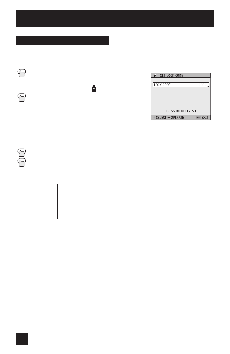
Set Lock Code
Channel guard and V-Chip settings are protected by a four-digit lock code. Your TV comes
pre-set with a lock code of “0000”. You may change the code to any four-digit number you
wish. To change the lock code, follow the steps below.
Press the MENU button
¥
The first digit will be highlighted
¥
Continue to follow these directions for all four numbers
When a viewer attempts to watch a blocked channel, this message appears:
To SET LOCK CODE
To operate (The lock icon appears)
Press ZERO to access the lock code
To select the number
To move to the next digit
Press the OK button to finish (your lock code is now set)
Press the Menu button when finished
THIS PROGRAMMING EXCEEDS
YOUR RATING LIMITS.
PLEASE ENTER LOCK CODE BY
10 KEY PAD TO UNLOCK IT.
NO. - - - -
The channel will remain blocked until the correct lock code is entered (see above for
information on setting your lock code).
Notes:
• After a power interruption you must reset the lock code.
• Write your lock code number down and keep it hidden from potential viewers.
• If you forget the lock code, a new code may be set using the steps listed above.
42
Page 43
Initial Setup
Auto Demo
This function lets you preview the many different viewing modes of your TV. It will cycle
through “index”, “split demo”, “freeze”, all of the different “aspect” ratios and all of the
different “video status” modes.
Press the MENU button
To AUTO DEMO
¥
Notes:
• Auto demo starts 2 seconds after it is set to ON.
• To stop auto demo, press the MENU button, and select
Power Indicator
Power indicator allows you to adjust the brightness of
the power indicator.
¥
To turn AUTO DEMO ON or OFF
auto demo by pressing the
ENU button to finish.
the M
Press the MENU button
To POWER INDICATOR
To adjust POWER INDICATOR LOW, HIGH or
OFF
buttons, and turn it off by pressing the
¥
buttons. Press
Position Adjustment
Position adjustment allows you to adjust the position of the picture on the screen vertically
when the aspect is set to panorama, cinema, or full.
Press the MENU button
To POSITION ADJUSTMENT
¥
Notes:
• To reset the adjustment to the center, press the O
• When the arrow disappears, while you are adjusting the position, the position is at its
• If you select regular size with aspect or Multi Screen, position adjustment option is not
• When you change the screen size, perform the position adjustment again.
• Position adjustment allows you to adjust the screen position vertically and horizontally when
To enter
¥
To adjust the position
Press the MENU button to finish
K button.
maximum limit.
seen.
the aspect is set HD panorama or cinema zoom for 1080i signal.
43
Page 44

Initial Setup
Digital-In
The DIGITAL-IN option can only be displayed in the INITIAL SETUP menu when a 480p picture
signal is being input to the DIGITAL-IN terminal.
This option adjusts the position when a 480p picture signal is being displayed on the screen.
There are two types of 480p picture signals: 640x480 and 720x480. If the displayed picture is
slightly shifted, the position can be adjusted by selecting either SIZE1 or SIZE2.
Press the MENU button
To DIGITAL-IN
¥
To enter
¥
To select SIZE1 or SIZE2
Press the MENU button to finish
Note:
The DIGITAL-IN menu can only be displayed when a 480p picture signal is input to the
Digital-In terminal and the picture is being displayed on the screen.
TV Speaker
If your TV is connected to a stereo system, you can turn off the TV speakers and listen to the
audio through your stereo.
Press the MENU button
¥
Notes:
• Before you turn the TV speaker setting from OFF to ON, make sure that the TV volume
• After a power interruption, the TV speaker settings will return to “ON”.
To TV SPEAKER
To turn the TV’s speakers ON or OFF
Press the MENU button when finished
level is low! If the TV volume is set too high, the sound level will be extremely loud.
44
Page 45

Initial Setup
Audio Out
If your television is connected to an external speaker source, audio out gives you the option of
controlling the volume level with your TV’s remote control.
Press the MENU button
To AUDIO OUT
¥
To VARI or FIX
Press the MENU button when finished
VARI: Lets you adjust the volume of the external speakers
using the VOLUME +/– buttons on your TV’s remote control.
FIX: The volume of the external speakers is adjusted using
the audio device’s remote control.
Image Shift
The picture displayed on the screen is shifted up, down and to the left and right at regular
intervals. In order to prevent burn-in, set this function to FAST or STANDARD.
Press the MENU button
To IMAGE SHIFT
¥
“OFF”
To select the mode “STD (STANDARD)”, “FAST” or
Press the MENU button when finished
OFF: IMAGE SHIFT is turned off.
STD: The picture is shifted every 30 minutes.
FAST: The picture is shifted every 10 minutes.
Language
The language function is described on page 25 as the interactive plug-in menu. If you need to
choose the language again, follow the steps below.
Press the Menu button
¥
To LANGUAGE
To choose a language: ENG. (English), FRAN.
(French) or ESP. (Spanish)
Press the MENU button when finished
45
Page 46
Initial Setup
Closed Caption
Many broadcasts now include an onscreen display of dialog called closed captions. Some
broadcasts may also include displays of additional information in text form. Your television
can access and display this information using the closed caption feature. To activate the
closed caption feature, follow the steps below.
Press the MENU button
¥
¥
Notes:
• Closed caption subtitles are usually found on closed caption channel CC1. Some programs
• Closed captioning may not work correctly if the signal being received is weak or if you are
• Most broadcasts containing closed captioning will display a notice at the start of the
• To select the mode, press the C.C. button. See page 61.
To CLOSED CAPTION
To operate
To select CAPTION or TEXT
To select a caption (CC1 to CC4) or text channel
(T1 to T4)
Press the OK button to save
Press the MENU button when finished
may include additional text information which is usually found on text channel T1. The other
channels are available for future use.
playing a video tape.
program.
Noise Muting
This feature inserts a blank gray screen over channels which
are not broadcasting or are too weak to be received clearly.
Press the MENU button
¥
Note:
• Noise muting will not work during auto tuner setup or when you operate channel summary.
To NOISE MUTING
To turn noise muting ON or OFF
Press the MENU button when finished
46
Page 47
Initial Setup
Front Panel Lock
This allows you to lock the keys on the front of the TV, so that a child may not accidentally
change your viewing preferences.
Press the MENU button
To FRONT PANEL LOCK
¥
To turn ON or OFF
Press the MENU button when finished
You can turn off this feature in the following ways:
• Unplug the power cord, and plug it back in. Do this if
your batteries die, or you lose your remote control.
• Use the remote control.
• Press the MENU button on the front of the TV for more than 3 seconds. In this case, the
OSD for FRONT PANEL LOCK will appear.
Note:
• To turn ON/OFF the TV, press the power button for more than 3 seconds. This feature will
remain ON.
V1 Smart Input
This feature is used if you have connected an AV Receiver to your television. By turning this
feature on, your television can automatically detect the signal source from your components
that are connected to your AV Receiver. Refer to page 24 for how to connect an AV receiver to
your television.
Press the MENU button
To V1 SMART INPUT
¥
To turn ON or OFF
Press the MENU button when finished
Notes:
• If you do not have an AV Receiver connected to your television, turn this feature OFF. By
doing so, you can take advantage of using AV CompuLink components with your television.
• Some AV Receivers may not work with this function.
47
Page 48

Initial Setup
Auto Shut Off
This function automatically shuts off your TV when there is no signal from the channel the
TV is on.
Press the M
To AUTO SHUT OFF
¥
To turn ON or OFF
Press the MENU button when finished
• If the channel that you have on does not receive a
signal for more than one minute, the blinking text
“NOT RECEIVING A SIGNAL” appears on the screen, and
starts the countdown. If no signal is being received within
10 minutes, the TV shuts itself off.
XDS ID
XDS ID Display provides a channel’s call letters, the network’s name, and even a program
name. The XDS ID information is provided by the broadcaster.
Press the M
To XDS ID
¥
To turn ON or OFF
Press the MENU button when finished
ENU button
ENU button
48
Page 49

Picture Adjust
Picture Settings
These settings allow you to change and adjust the way the picture appears on your television.
TINT
Tint allows you to adjust the levels of red and green in your TV picture.
COLOR
The color function lets you make all the colors in the TV picture appear either more vivid or
subtle.
PICTURE
Picture allows you to adjust the levels of black and white on the TV screen, giving you a
darker or brighter picture overall.
BRIGHT
You can adjust the overall brightness of the TV picture with the Bright control.
DETAIL
The Detail feature adjusts the level of fine detail displayed in the picture.
Adjust the Picture Settings
Press the MENU button
To TINT, COLOR, PICTURE, BRIGHT or
DETAIL
¥
To enter
¥
To adjust the setting
To move to the next setting
Press the MENU button when finished
Color Temperature
You can decide how strong or dull the colors appear on the TV screen.
Press the MENU button
To COLOR TEMPERATURE
¥
To enter
¥
To set LOW or HIGH
Press the MENU button when finished
49
Page 50

Picture Adjust
Digital Noise Clear
With digital noise clear, this helps take our static or noise from a channel that may not be
coming in clearly.
Press the MENU button
To DIG. NOISE CLEAR
¥
To enter
To select the mode “LOW”, “HIGH” or “OFF”
Press the MENU button when finished
Color Management
This TV supports the COLOR MANAGEMENT function to ensure dull colors are compensated
to produce natural hues.
Press the MENU button
To COLOR MANAGEMENT
¥
To enter
To select the mode “VIVD”, “STD” or “OFF”
Press the MENU button when finished
Burn-in Image Reducer
When burn-in is minimal, burn-in and residual images may be softened with the BURN-IN
IMAGE REDUCER function.
Press the MENU button
To BURN-IN IMAGE REDUCER
¥
To enter
Burn-in will be reduced by displaying snow on the screen for approximately 55 seconds, and
white for approximately 5 seconds in sequence. Leave the television in this state for some time
(more than a few hours).
Push the MENU button to bring back to the normal screen.
Reset
Reset resets all picture adjustments (tint, color, picture, bright, detail, color temperature, dig.
noise clear and color management) at once to the default settings.
Press the M
To RESET
¥
To enter
The onscreen menu disappears for a moment, and
Press the MENU button when finished
then the settings are reset to the default setting for
all the picture adjustments.
ENU button
50
Page 51

Sound Adjust
Sound Settings
These settings allow you to change and adjust the way the picture appears on your television.
BASS – You can increase or decrease the level of low-frequency sound in the TV’s audio with
TREBLE – Use treble to adjust the level of high-frequency sound in your TV’s audio.
BALANCE – Adjust the level of sound between the TV’s left and right speakers with the
the bass adjustment.
balance setting.
Adjust the Sound Settings
Press the MENU button
To BASS, TREBLE or BALANCE
¥
To adjust the setting
To move to the next setting
Press the MENU button when finished
Notes:
• You can reset the sound adjustments (BASS, TREBLE and BALANCE) you set at once as
the default setting when you select reset. See page 50.
• You can adjust BALANCE only when A.H.S. is off. See page 57.
MTS (Multi-Channel Television Sound)
MTS technology allows several audio signals to be broadcast at once, giving you a choice
in what you wish to hear with a TV program. In addition to mono or stereo sound, an
MTS broadcast may also include a second audio program (SAP).
Press the MENU button
¥
(The ON AIR arrow tells you if a broadcast is in stereo and/or
contains an SAP).
Press the MENU button when finished
Notes:
• Keep the TV in stereo mode to get the best sound quality. The sound will work in stereo
• Choose the mono setting to reduce excessive noise on a certain channel or broadcast.
• Selecting SAP will allow you to hear an alternative soundtrack, if one is available.
• MTS unavailable if your television’s input source is in input 1, 2, 3 or 4 mode, as described
To MTS
Select the mode
mode even if a certain broadcast is in mono sound only.
on page 56.
51
Page 52

Clock/Timers
Set Clock
The set clock function is described on page 26 as the interactive plug-in menu. You can
choose to set the clock automatically, or manually. If you need to set the clock again, follow
the steps below.
Press the MENU button
To SET CLOCK
¥
To operate
When you set the clock automatically, choose AUTO by pressing the ¥or arrows.
¥
¥
Press OK to finish
Press the MENU button when finished
When you set the clock manually, choose MANUAL by pressing the
¥
¥
Press OK to start clock
To TIME ZONE
To select your time zone
To D.S.T. (daylight savings time)
To turn D.S.T. ON or OFF
To move to the hour
To set the hour
To move to minutes
To set the minutes
¥
or arrows.
Press the MENU button when finished
52
Page 53

Clock/Timers
On/Off Timer
The on/off timer lets you program your television to turn itself on or off. You can use it as an
alarm to wake up, to help you remember important programs, or as a decoy when you’re not
home.
Press the M
¥
¥
¥
¥
¥
¥
¥
Press the OK button to finish
Press the MENU button to exit the menu
To ON/OFF TIMER
To operate (begins with ON TIME)
To set the hour (AM/PM) you want the TV to turn on
To move to minutes
To set the minutes
To accept ON TIME and move to OFF TIME (the time
the TV will turn off). Set the OFF TIME the same way as ON TIME
To accept OFF TIME and move to CHANNEL
To select channel
To ON VOLUME
To set the volume level
To move to MODE
Choose ONCE or EVERYDAY
To ON/OFF TIMER
Choose YES to accept the timer setting, choose NO if you don’t wish to accept
ENU button
Notes:
• The on/off time cannot be set to locked or guarded channels.
• In order for the on/off timer to work, the clock must be set.
• After a power interruption, the timer settings must be reset.
53
Page 54

Button Functions
Multi Screen Function
Your television has two kinds of screen: SPLIT (2 channels) and INDEX (12 channels).
Note: After you press any multiscreen button, if you press the menu button, only the picture
adjust screen will appear.
Split
Activate the split-screen option by pressing SPLIT on the remote control.
A channel and input will now appear onscreen. The
channel (or input) you were watching before pressing
SPLIT will appear on the left, the input will appear on
the right. The sound will continue to come from the
main screen channel (or input). To turn split-screen
off and return to normal television viewing, press
PLIT again or press the BACK button.
S
Notes:
• You can enter the SPLIT mode when the screen is in NORMAL or INDEX mode.
• Split-screen functions will not work with locked channels or channels blocked by V-Chip
ratings limits. A grey screen will display instead.
• With split screen, the picture from the component terminal and HDCP terminal will not be
displayed.
• The aspect of MAIN CHANNEL PICTURE becomes 16:9 when you input the picture of
480p, 720p and 1080i from the component terminal and HDCP terminal.
• After you press the Select button, and select SPLIT SCREEN when you press the
OK button, select normal screen. If you don’t operate, the MAIN CHANNEL SCREEN will
be automatically selected about 8 seconds later.
• Main channel picture and split-screen will not display the same RF channel and same
input.
54
Page 55

Button Functions
Index
This allows you to quickly look at up to 12 channels at a time so that you can decide which
one to watch.
Notes:
• Only RF input signal will be displayed.
• You can watch the channel added in channel summary. See page 35.
Freeze
Pressing the FREEZE button causes the screen to change to the split-screen display with the
still picture displayed on the right. In order to return to the normal display, press the F
button once again.
Note: When the screen is in freeze mode, if you do not operate it within 15 minutes, this
function will cancel out.
REEZE
Swap
You can exchange the channel (or input) displayed in the split screen window for the main
screen image by pressing the SWAP button.
Note: It will only work in SPLIT mode.
Select
With SELECT, you can select the picture (channel) while viewing SPLIT screen. When you
press SELECT button, the channel number on the top will be highlighted. Each press of SELECT
will shift the channel.
55
Page 56

Button Functions
Power
Turns the TV on or off.
Press the P
Number Buttons - 10Key Pad
Use the number buttons on the remote control to move directly to a specific channel. For
example, to move to channel 7:
0 (Zero)
7 (Seven)
100+ Button
Use the 100+ button to directly access channels above channel 99. For example, to move to
channel 124, press 100+, 2 (Two), 4 (Four).
Input
Selects the signal input source for the television: Input-1, 2, 3 or 4 for video devices like
VCR’s DVD players, or camcorders.
INPUT 1, 2, 3, 4
OWER button
Note:
• When you return to TV mode, press the R
ETURN +/TV button or direct 10 key pad.
Digital-In
Use this button to directly select the digital-in input.
Press the DIGITAL-IN button
• Digital-In will display only when the 480p picture signal in Digital-In is displayed.
56
Page 57

Button Functions
Return +/TV
The return+/TV button has three functions:
Return - Returns to the channel viewed just before the channel currently onscreen.
Return+ - Lets you program a specific channel to return to while scanning through the
TV - Returns to the TV mode.
R
RETURN+/TV
• To cancel your return+ channel, press and hold the R
• Return+ works only with the Channel+/– buttons. Pressing any number key will cancel
channels using the CH+ and CH– buttons.
ETURN+/TV and hold for three seconds
RETURN CHANNEL
PROGRAMMED !
The channel currently active has been programmed as your return+ channel.
Now scan through the channels using the C
You will return to your programmed channel.
message “RETURN CHANNEL CANCELLED!” will appear.
return+.
HANNEL+/– buttons.
ETURN+ button for three seconds. The
Sound
By pressing the sound button, you can change the A.H.S. (Advanced Hyper Surround) mode,
BBE and A.H.B. (Active Hyper Bass) mode.
A.H.S. - Adds a more spacious surround sound. Music gives basic effect and movie for more
BBE - BBE high definition audio adds natural, clear and extraordinary sound quality to any
A.H.B. - You can reinforce the bass sound to maintain rich, full bass at low volumes, and
Press the S
¥
Press the MENU when finished
Note: BBE is a registered trademark of BBE Sound, Inc. For U.S., licensed from
BBE Sound, Inc. under USP 4638258, 4482866 and 5510572. For Canada, licensed from
BBE Sound, Inc. BBE is a registered trademark of BBE Sound, Inc.
effect.
program.
enjoy a clear sound with boosted bass.
OUND button
To select A.H.S., BBE or A.H.B.
To choose the setting
57
Page 58
Button Functions
Muting
The MUTING button instantly turns the volume down completely when you press it. Press
UTING and the volume level will instantly go to zero. To restore the volume to its previous
M
level, press M
Video Status
The Video status button gives you a choice of four TV picture display settings, including a
display of your own preferences.
Standard - Resets the picture display to the standard settings.
Dynamic - Gives a vivid picture with better contrast when viewing
Theater - Gives a rich, film-like look to video when viewing in a
Game - Used for when you are playing video games connected to
Press the V
By every press of the VIDEO STATUS button, you change the mode.
Notes:
• You can also change the mode by pressing the
• The VIDEO STATUS function is initially set to DYNAMIC. Unless the TV is being watched
in an extremely bright room, it is recommended to change the VIDEO STATUS setting to
standard, theater or game. Doing so will reduce the chance of PDP burn-in and extend the
life of the PDP.
UTING again.
in a brightly lit room.
dimly lit room.
your TV.
IDEO STATUS button
buttons.
Natural Cinema
Natural cinema corrects the problem of blurred edges which may occur when viewing a
program originally shot on film (such as motion pictures) or animation. If you notice blurring
at the edges of these programs, press N
helps correct conversion errors that occur when film, which is shot at 24 frames-per-second,
is broadcast at the television rate of 30 frames-per-second.
Press the NATURAL CINEMA button
Note: The natural cinema mode is automatically set to “AUTO” in
the following cases:
• Turning on or off
• Changing the channel or input mode
• Using multi-screen functions
ATURAL CINEMA and set it to AUTO. Natural Cinema
TheaterPro D6500K
The TheaterPro D6500K color temperature technology function makes sure that the video you
watch is set to the standard color temperature, so that what you see is as true to what the
film to video editors intended it to be.
Press the T
HEATERPRO button
58
Page 59
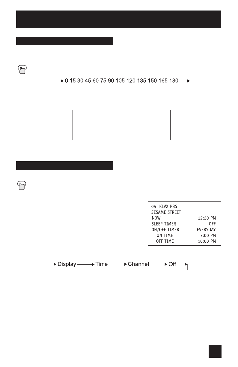
Button Functions
Sleep Timer
The Sleep Timer can turn the TV off for you after you fall asleep. Program it to work in
intervals of 15 minutes, for a total time of up to 180 minutes.
Press the S
LEEP TIMER button
Sleep Timer Message
20 seconds before the automatic shutoff, this message will appear:
GOOD NIGHT!!
PUSH SLEEP TIMER BUTTON
TO EXTEND.
You then have 20 seconds to press the S
delay the shut off for another 15 minutes.
LEEP TIMER button to
Display
The display screen shows the current status of timers, inputs, and XDS ID.
Press the DISPLAY button
The screen to the right shows the following information:
The current channel or AV input (Channel 05)
•
• The current time (12:20 pm)
• Sleep timer status/minutes remaining (The Sleep Timer
is off)
• On/off timer status (Set to turn on everyday at 7:00 PM,
off at 10:00 PM)
• Each Press of the DISPLAY button changes the display mode:
Display - Full screen shown above
Time - Shows the current time only
Channel - Shows the current channel
Off - Turns display off
Notes:
• You may also turn off the display at any step by pressing M
• If the clock, sleep timer or on/off timer are not set, the display screen will show:
“CLOCK NOT SET”, “SLEEP TIMER OFF”, and “ON/OFF TIMER OFF” respectively.
ENU.
59
Page 60
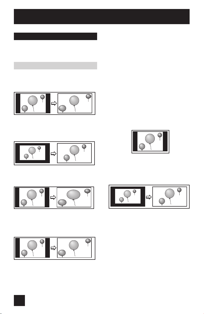
Button Functions
Aspect
This feature will help you adjust the picture you are watching to give you the best possible
picture quality.
Aspect Ratios
PANORAMA - With this ratio a normal
4:3 aspect picture is stretched to fit the
dimensions of the 16:9 aspect screen.
CINEMA - This ratio “zooms in” on
the center part of a 4:3 aspect picture,
blowing it up to fill the 16:9 screen.
FULL - This is the ratio to use when
watching 16:9 High-Definition broadcasts.
HD PANORAMA - This ratio streches
the High-Definition 16:9 aspect image to
eliminate the black side bars.
REGULAR - The regular ratio is used
when you want to watch a 4:3 broadcast
or recorded program without modifying
the original picture to fit the dimensions
of your 16:9 screen. The 4:3 picture
will fil lthe screen from top to bottom,
while black bars will appear to fill up the
remaining space along the picture’s sides.
The 4:3 picture will be centered within the
boundaries of the 16:9 screen.
CINEMA ZOOM - This ratio streches
the High-Definition 16:9 aspect image to
eliminate the black surrounding bars.
60
Page 61
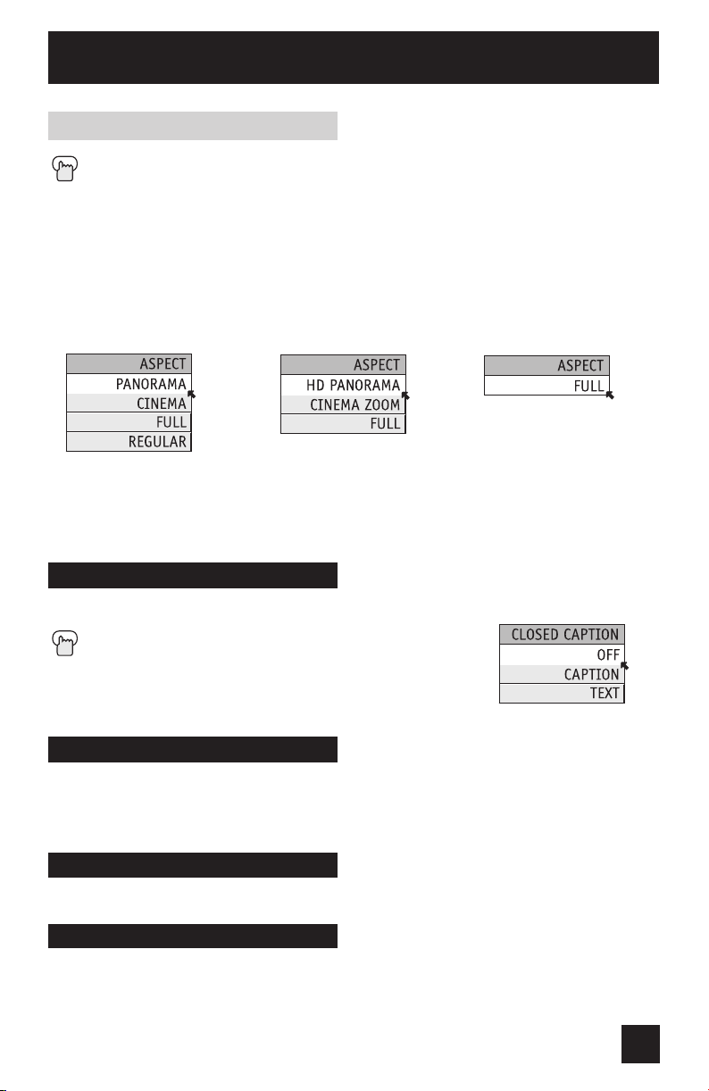
Button Functions
Aspect Ratios (Continued)
Press the ASPECT button
• By pressing the A
When you change the aspect ratios, it is different from their broadcast or recorded program.
NTSC, 480i, 480p,
HDCP 480p
Notes:
• You can also choose the size by pressing the
• When you change the aspect ratio or signal, reset the picture position to center.
C.C. (Closed Caption)
SPECT button, you can change the size.
HD, HDCP 1080i
buttons.
720P, HDCP 720p
Use the C.C. (Closed Caption) button to select the mode of closed caption.
Press the C.C. button
• See page 46 when you set the caption/text mode.
Menu
The MENU button allows you to access JVC’s onscreen menu system. Press MENU to activate
the onscreen menu system.
• See individual topics like “Sound Adjust” for specific information on using menus.
OK
This button confirms your selection when you are in one of the onscreen menus.
Back
This button allows you to go back in the menu to change a selection or correct a mistake.
61
Page 62

Button Functions
TV/CATV Slide Switch
Use either the television’s own tuner or a cable box to select channels. Set this switch to TV
to operate the television’s built-in tuner. Move the switch to CATV to operate a cable box.
Note:
• See page 28 for information on programming your remote for cable box operation.
VCR/DVD Slide Switch
You can control a VCR or DVD player with the buttons on the lower part of the remote control.
Move the slide switch to VCR or DVD to operate.
Notes:
• The remote is preset with the code 000 to control JVC-brand VCR’s. For any other
manufacturer’s brand VCR, please see the code chart and instructions on page 29.
• The remote is preset with the code 000 to control JVC-brand DVD players. For any other
manufacturer’s brand DVD player, please see the code chart and instructions on page 30.
VCR Buttons
You can use this remote control to operate the basic functions of your VCR. These functions
include: play, record, rewind, fast-forward, stop, pause, channel scan, TV/VCR, power on, and
power off.
Move the selector switch to VCR to operate.
• The remote is preset with the code 000 to control JVC-brand VCR’s. For any other
manufacturer’s brand VCR, please see the code chart and instructions on page 29.
DVD Buttons
You can also use this remote control to operate the basic functions of your DVD player. These
functions include: play, rewind, fast-forward, stop, still/pause, previous/next, tray open/close,
power on, and power off.
Move the selector switch to DVD to operate.
• The remote is preset with the code 000 to control JVC-brand DVD players. For any other
manufacturer’s brand DVD player, please see the code chart and instructions on page 30.
Light
Your remote control includes illuminated buttons for key features like Channel +/– and
Volume +/–. Press the light button to turn the illumination on for 4 seconds.
62
Page 63
Troubleshooting
Refer to the table below to check the condition. If you think that there is a problem, contact
the JVC Service Center where you purchased the television.
PROBLEMS CHECK
There is no power
The power lamps do
not light even though
the TV is on
There is no picture or
sound
Remote control is not
operating properly or
at all
You cannot select a
certain channel
The power turns off
by itself
It does not operate
correctly
The clock is wrong The power was interrupted and the clock was not reset. See page 52.
The color quality is
poor
There are line across
the picture
The picture is spotted
- Check for a blown fuse or circuit breaker or a power outage.
- Check that the plugs on the power cords from the TV and receiver are
connected to wall outlets.
Check that POWER INDICATOR in the MENU is not set to OFF.
- The antenna could be disconnected.
- The input mode could be set improperly. See page 56.
- The tuner (AUTO TUNER SETUP) could be set improperly. See page 35.
- The TV station may be having difficulties. Check to see if other stations
are working.
- Check to see that the batteries are still working and properly installed.
- Make sure the remote has a clear sight path to the TV.
- Check that the TV/CATV switch is in the proper position.
- You may be too far from the TV. You must be within 23 feet (7 meters).
- Use the remote control while pointing it at the screen.
- Make sure the channels have been programmed. See “Channel
Summary” on page 35.
- Check to see if the channel is locked. See “Channel Summary - Lock”
page 36.
- Make sure the set did not become unplugged.
- Perhaps the ON/OFF TIMER is set. See page 53.
- Check to see if the Sleep Timer was set. See page 59.
This television is operated by a microprocessor. It is possible that external
noise or interference is causing the problem. If the television does not
function correctly, remove the power plugs of the TV and Receiver from
the wall outlets and wait a while before inserting them into the wall outlets
again and operating the television.
- Tint and Color may be improperly adjusted. See page 49.
- The VIDEO STATUS mode may be turned to the wrong setting. See
page 58.
There could be interference from another electrical appliance, such as a
computer, another TV or VCR. Move any such appliances further away
from the TV.
There could be interference from a high-wattage appliance, like a hair
dryer or vacuum, operating nearby. Move the antenna away from the
appliance or change to a coaxial cable connection which is less prone to
interference.
63
Page 64

Troubleshooting
PROBLEMS CHECK
There are double
picures (ghosts)
Picture is snowy
(image noise)
Screen is 80% black
Stereo or bilingual
programs cannot be
heard
You hear occasional
crackling sounds
A building or passing airplane can reflec the original signal and produce a
second, slightly delayed one. Adjust your antenna position.
• Your antenna may be damaged, disconnected or turned.
• Check the antenna connection, page 19 in Quick setup.
If the antenna is damaged, replace it.
The Closed Caption Text mode is on. Turn it off in the CLOSED CAPTION
Menu, see page 61.
Make sure the MTS settings are correct. See “MTS” on page 51.
It is normal for the TV to make cracking sounds when first turned on or
off. Unless the sound or picture becomes abnormal, this is fine.
The following are not malfunctions.
• The television may make a creaking sound if the temperature of the room or the
temperature of the inside of the television changes. If there is no problem with the screen or
sound, then there is no need to worry.
• Although the picture may be temporarily disturbed and noise may be seen on the screen if
the power is turned on immediately after it has been turned off, this is not a malfunction.
• If the television is used at a location above 2,000 m, a buzzing noise and image distortion
may occur. This phenomenon is peculiar to PDP (Plasma Display Panel), and could occur
with any television using PDP. It is not a malfunction.
64
Page 65

Warnings
Caring for the Cabinet
Normally, light dusting with a soft, non-scratching duster will keep your TV clean.
If you wish to wipe down the television, first unplug it. Then wipe gently with a soft cloth,
slightly moistened with water. You can add a few drops of mild liquid detergent to the water to
help remove spots of oily dirt.
DO NOT allow liquid to enter the TV through the ventilation slots.
DO NOT use strong or abrasive cleaners on the TV.
DO NOT spray liquids or cleaners directly on the TV’s surface.
DO NOT rub or scrub the TV harshly. Wipe the set gently with a soft cloth.
Caring for the Screen
When it gets dirty, wipe it gently with a soft cloth.
Do not apply alcohol, organic solvents (like acetone), acidic or alkaline cleansers to the
screen. These will remove the coating layer and cause discolorations.
65
Page 66

Warranty
JVC COMPANY OF AMERICA warrants this product and all parts thereof, except as set forth
below ONLY TO THE ORIGINAL PURCHASER AT RETAIL to be FREE FROM DEFECTIVE
MATERIALS AND WORKMANSHIP from the date of original retail purchase for the period shown
below. (“The Warranty Period”)
PARTS 1 YEAR
This limited warranty is valid only in the fifty (50) United States, The District of Columbia
and Commonwealth of Puerto Rico.
WHAT WE WILL DO:
If this product is found to be defective within the warranty period, JVC will repair or replace
defective parts at no charge to the original owner.
Such repair and replacement services shall be rendered during regular business hours by JVC
authorized service centers. Parts used for replacement are warranted only for the remainder of
this Warranty Period. Televisions with a screen size of 25 inches and larger are covered on
an in-home basis.
WHAT YOU MUST DO FOR WARRANTY SERVICE:
Either contact the selling dealer (retailer) or call 1-800-252-5722 to arrange In-home
service. In-home service will require clear access to the Television by the service
technician.
WHAT IS NOT COVERED:
This limited warranty provided by JVC does not cover:
1. Products which have been subject to abuse, accident, alteration, modification, tampering,
negligence, misuse, faulty installation, lack of reasonable care, or if repaired or serviced by
anyone other than a service facility authorized by JVC to render such service, or if affixed
to any attachment not provided with the products, or if the model or serial number has
been altered, tampered with, defaced or removed. If the upper unit is removed from the
lower unit by anyone other than a dealer or service facility authorized by JVC.
2. Initial installation, installation and removal from “built-in” entertainment centers and other
mounting systems.
3. Operational adjustments covered in the Owner’s Manual, normal maintenance, including
head cleaning.
4. Damage that occurs in shipment, due to an act of God, and cosmetic damage.
5. Signal reception problems and failures due to line power surge.
6. Products used for commercial purposes (including but not limited to rental).
7. Accessories.
8. Batteries (except that Rechargeable Batteries are covered for 90 days from date of
purchase).
There are no express warranties except as listed above.
LABOR 1 YEAR
66
Page 67

Warranty
THE DURATION OF ANY IMPLIED WARRANTIES, INCLUDING THE IMPLIED WARRANTY OF
MERCHANTABILTY, IS LIMITED TO THE DURATION OF THE EXPRESS WARRANTY HEREIN.
JVC SHALL NOT BE LIABLE FOR THE LOSS OF USE OF THE PRODUCT, INCONVENIENCE,
OR ANY OTHER DAMAGES, WHETHER DIRECT, INCIDENTAL OR CONSEQUENTIAL
(INCLUDING, WITHOUT LIMITATION, DAMAGE TO TAPES, RECORDS OR DISCS)
RESULTING FROM THE USE OF THIS PRODUCT, OR ARISING OUT OF ANY BREACH
OF THIS WARRANTY, ALL EXPRESS AND IMPLIED WARRANTIES, INCLUDING THE
WARRANTIES OF MERCHANTABILITY AND FITNESS FOR PARTICULAR PURPOSE, ARE
LIMITED TO THE WARRANTY PERIOD SET FORTH ABOVE.
Some states do not allow the exclusion of incidental or consequential damages or limitations
on how long the warranty lasts, so these exclusions or limitations may not apply to you. This
warranty gives you specific legal rights and you may also have other rights which vary state
to state.
JVC COMPANY OF AMERICA 1700 Valley Road
DIVISION OF JVC AMERICAS CORP. Wayne, New Jersey 07470
http://www.jvc.com
REFURBISHED PRODUCTS CARRY A SEPARATE WARRANTY. THIS WARRANTY DOES
NOT APPLY. FOR DETAILS OF REFURBISHED PRODUCT WARRANTY, PLEASE REFER
TO THE REFURBISHED PRODUCT WARRANTY INFORMATION PACKAGED WITH EACH
REFURBISHED PRODUCT.
For customer use:
Enter below the Model No. and Serial No. which is located either on the rear, bottom or
side of the cabinet.
Retain this information for future reference.
Model No.: Serial No.:
Purchase Date: Name Of Dealer:
67
Page 68

Authorized Service Centers
QUALITY SERVICE
HOW TO LOCATE YOUR JVC SERVICE CENTER
TOLL FREE: 1 (800) 537-5722
http://www.jvc.com
Dear Customer,
In order to receive the most satisfaction from your purchase, please read the instruction
booklet before operating the unit. In the event that repairs are necessary, call our Customer
Relations Department at 1-800-537-5722 or visit our website at www.JVC.com
Remember to retain your Bill of Sale for Warranty Service.
Don’t service the television yourself
Caution
To prevent electrical shock, do not open the cabinet. There are no user serviceable parts
inside. Please refer to qualified service personnel for repairs.
Accessories
To purchase accessories for your JVC product, please call toll free:1 (800) 882-2345 or on the
web at www.JVC.com
68
Page 69

Specifications
MODEL PD-42WX84
Type Plasma Display
Reception Format
Reception Range
Power Source AC 120V, 60Hz
Power Consumption
Screen Size 42 inch / 107.5 cm measured diagonally, 16:9 ratio
Audio Output 18W + 18W
Speakers
Anntenna Terminal 75 ohms (VHF/UHF) (F-type connector)
External Input Jacks
S-Video Input Jacks
Component Input Jacks
Audio Output Jacks
(VARI/FIX)
Subwoofer Output Jack
AV Compu Link III Jack 3.5 mm mini jack x 1
Digital-In
Dimensions
W X H X D
Weight
Accesories Refer to "Unpacking your TV" on page 10.
FIX: 500mVrms (-4dBs) Low impedance (400 Hz when modulated 100%)
Note: The Digital-In terminal is not compatible with picture signals of a personal computer
45 11/16 x 31 7/16 x 12 3/16 inch / 1160 x 798 x 308mm (with the stand)
45 11/16 x 28 13/16 x 3 7/8 inch / 1160 x 731 x 98 mm (main TV body)
Receiver : 17 3/16 x 3 15/16 x 15 1/16 inch / 435 x 99 x 382 mm
NTSC, BTSC System (Multi-Channel Sound)
1080i DTV digital broadcast ready
VHF 2 to 13, UHT 14 to 69 Sub, Mid, Super, Hyper et Ultra bands
(180 channel frequency synthesizer system)
TV : 365W
Receiver : 29W
DD speaker (3 3/4 x 7/16 inch / 9.5 cm x 1 cm) oval x 2
Tweeter: ( 13/16 inch / 2 cm) round x 2
Woofer ( 5 1/8 x 2 9/16 / 13 cm x 6.5 cm) oval x 2
Video : 1Vp-p, 75 ohms
Audio : 500mVrms (-4dBs) high impedance
Y : 1Vp-p positive, 75 ohms (negative sync provided)
C: 0.286 Vp-p (burst signal), 75 ohms
Y : 1Vp-p positive, 75 ohms (negative sync provided)
VARI: More than 0 to 1000mVrms (+2.2 dBs)
Low impedance (100 Hz when modulated 100%)
b/Pr: 0.7 Vp-p, 75 ohms
P
More than 0 to 1000mVrms (+2.2 dBs)
DVI-D single Link 19 pin
TV:
106 lbs / 48 kg (with the stand)
84 lbs / 38 kg (main TV body)
Receiver : 11.3 lbs / 5.1 kg
TV:
Specifications subject to change without notice.
69
Page 70

Notes
70
Page 71

Notes
71
Page 72

JVC COMPANY OF AMERICA
Division of JVC Americas Corp.
1700 Valley Road
Wayne, New Jersey, 07470
JVC CANADA, INC.
21 Finchdene Square
Scarborough, Ontario
Canada, M1X 1A7
 Loading...