

Page 1
52108200301
SERVICE MANUAL
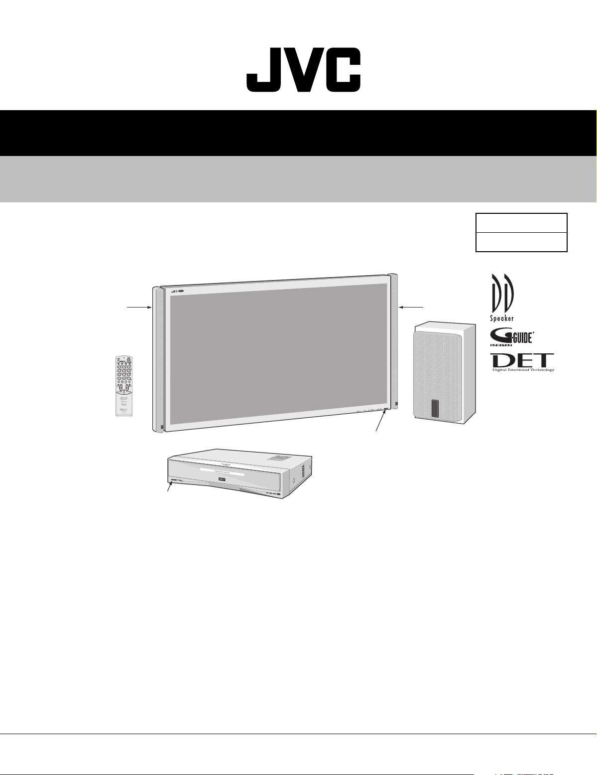
PDP COLOR TELEVISION
PD-42DXT
PD-42DXT
BASIC CHASSIS
SB3
TS-42DXT
[FRONT SPEAKER (L)]
[RM-C289]
PD-42DXT
[PLASMA DISPLAY UNIT]
TU-42DXT
[RECEIVER UNIT]
TS-42DXT
[FRONT SPEAKER (R)]
TS-42DXT
[SUB WOOFER]
TABLE OF CONTENTS
1 PRECAUTIONS . . . . . . . . . . . . . . . . . . . . . . . . . . . . . . . . . . . . . . . . . . . . . . . . . . . . . . . . . . . . . . . . . . . . . . . 1-3
2 SPECIFIC SERVICE INSTRUCTIONS . . . . . . . . . . . . . . . . . . . . . . . . . . . . . . . . . . . . . . . . . . . . . . . . . . . . . . 1-6
3 ADJUSTMENTS . . . . . . . . . . . . . . . . . . . . . . . . . . . . . . . . . . . . . . . . . . . . . . . . . . . . . . . . . . . . . . . . . . . . . . 1-20
4 TROUBLE SHOOTING. . . . . . . . . . . . . . . . . . . . . . . . . . . . . . . . . . . . . . . . . . . . . . . . . . . . . . . . . . . . . . . . . 1-52
COPYRIGHT © 2003 VICTOR COMPANY OF JAPAN, LTD.
No.52108
2003/01
Page 2
PD-42DXT
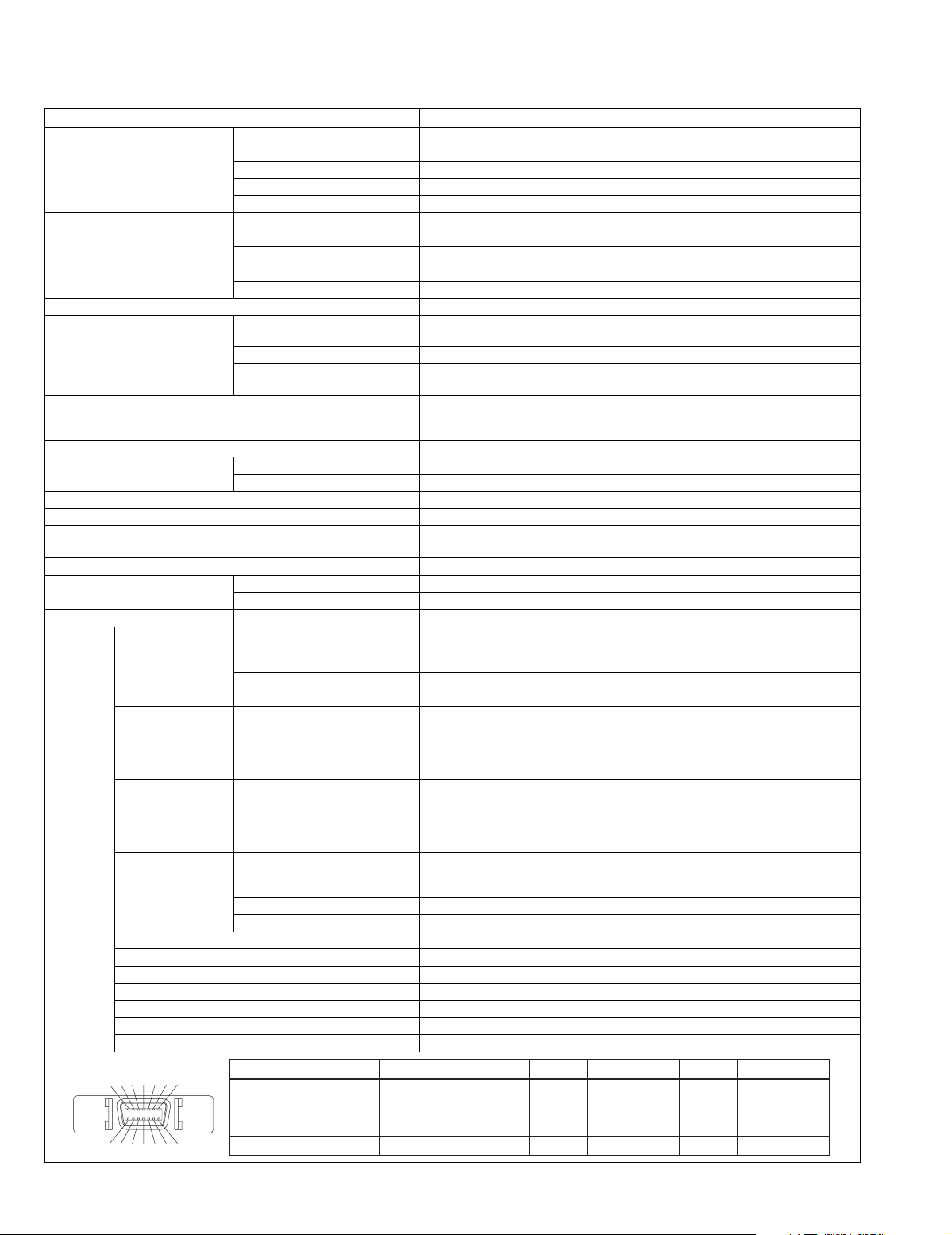
SPECIFICATION
Item Contents
Dimensions (W x H x D) Plasma display unit 103.5cm x 64.0cm x 9.8cm (without Front speaker)
112.3cm x 64.0cm x 10cm (with Front speaker)
Receiver unit 43.5cm x 9.9cm x 38.2cm
Front speaker 4.2cm x 63.9cm x 5.4cm
Sub woofer 3.5cm x 23.0cm x 12.6cm
Mass Plasma display unit 33.0kg (without Front speaker)
35.5kg (with Front speaker)
Receiver unit 5.6kg
Front speaker 0.8kg (per one speaker without attachment metal)
Sub woofer 3.7kg
Color System NTSC-M
Receiving frequency VHF 91.25MHz~103.25MHz (1~3ch)
UHF 471.25MHz~765.25MH (13~62ch)
CATV 109.25MHz~165.25MHz (C13~C22ch)
Intermediate frequency Video: 58.75MHz
Power Input AC110V, 50Hz/60Hz
Power Consumption Plasma display unit Operate: 360W, Stand by: 0.4W
Receiver unit Operate: 41W, Stand by: 0.8W
Plasma display panel (PDP) 42-inch wide aspect (16:9) QLE0020-001
Screen size (W x H x D) 92.1cm x 51.8cm x 105.7cm
Display pixels Horizontal: 1024 dots
Audio output
Speaker Front speaker 9.5cm x 1cm square x 2
Sub woofer (for bass sound) 16cm Round x 1
Aerial input VHF/UHF 75 ohm Unbalanced Coaxial
VIDEO/AUDIO IN
VIDEO 1
VIDEO 2
VIDEO 3 (DVD)
VIDEO 4
VIDEO 3/DVD
COMPONENT
VIDEO IN
D4 VIDEO IN
(VIDEO 1: D-VHS,
VIDEO 4)
Input /
Output jack
MONITOR /
REC OUT S1-VIDEO
AUDIO OUT (Fixed) 500mV (rms), Low Impedance RCA pin jack x 2
Headphone 3.5mm Stereo mini jack x 1
AV COMPULINK III 3.5mm mini jack x 1
i-LINK IN/OUT 4 Pin S400 x 2
Optical digital audio output -18dBm, 660nm (MPEG 2 AAC or PCM according to the menu settings)
Telephone line 2P Modular jack, Modem transmission rate 2400bps
Video remote controller 3.5mm mini jack
D TERMINAL (Pin layout)
12 34567
8
91011121314
S1-VIDEO
(VIDEO 4: S-VIDEO)
VIDEO 1V (p-p) Positive (Negative sync provided), 75 ohm RCA pin jack x 4
AUDIO 500mV (rms), High Impedance RCA pin jack x 8
1125i / 750p
525p / 525i
1125i / 750p
525p / 525i
VIDEO 1V (p-p), 75 ohm, Negative sync RCA pin jack x 2
AUDIO 500mV (rms), Low Impedance RCA pin jack x 2
Pin No. Signal name Pin No. Signal name Pin No. Signal name Pin No. Signal name
1 Y 5 Pr/Cr 9 LINE-2 13 Spare line 3
2 Y GND 6 Pr/Cr GND 10 Spare line 2 14 Switch
3 Pb/Cb 7 Spare line 1 11 LINE-3
4 Pb/Cb GND 8 LINE-1 12 Switch GND
171.25MHz~217.25MHz (4~12ch)
223.25MHz~313.25MHz (C23~C38ch)
Sound: 54.25MHz
Color: 55.17MHz (3.58MHz)
Vertical: 768 dots
Front: 10W+10W, Sub woofer: 15W
Mini DIN4 pin x 3
Y: 1V (p-p) Positive (Negative sync provided), 75 ohm
C: 0.286V (p-p) (Burst signal), 75 ohm
RCA pin jack x 3
Y: 1V (p-p) (Sync signal: ±0.35V(p-p), 3-value sync.), 75 ohm
Pb/Pr: ±0.35V(p-p), 75 ohm
Y: 1V (p-p) Positive (Negative sync provided), 75 ohm
Cb/Cr: 0.7V(p-p), 75 ohm
2 sequences 14pin x 1
Y: 1V (p-p) (Sync signal: ±0.35V(p-p), 3-value sync.), 75 ohm
Pb/Pr: ±0.35V(p-p), 75 ohm
Y: 1V (p-p) Positive (Negative sync provided), 75 ohm
Cb/Cr: 0.7V(p-p), 75 ohm
Mini DIN4 pin x 1
Y: 1V (p-p) Positive (Negative sync provided), 75 ohm
C: 0.286V (p-p) (Burst signal), 75 ohm
1-2 (No.52108)
Page 3

SECTION 1
PRECAUTIONS
PD-42DXT
1.1 SAFETY PRECAUTIONS
(1) The design of this product contains special hardware,
many circuits and components specially for safety
purposes. For continued protection, no changes should be
made to the original design unless authorized in writing by
the manufacturer. Replacement parts must be identical to
those used in the original circuits. Service should be
performed by qualified personnel only.
(2) Alterations of the design or circuitry of the products should
not be made. Any design alterations or additions will void
the manufacturer's warranty and will further relieve the
manufacturer of responsibility for personal injury or
property damage resulting therefrom.
(3) Many electrical and mechanical parts in the products have
special safety-related characteristics. These
characteristics are often not evident from visual inspection
nor can the protection afforded by them necessarily be
obtained by using replacement components rated for
higher voltage, wattage, etc. Replacement parts which
have these special safety characteristics are identified in
the parts list of Service manual. Electrical components
having such features are identified by shading on the
schematics and by ( ) on the parts list in Service
manual. The use of a substitute replacement which does
not have the same safety characteristics as the
recommended replacement part shown in the parts list of
Service manual may cause shock, fire, or other hazards.
(4) Don't short between the LIVE side ground and ISOLAT-
ED (NEUTRAL) side ground or EARTH side ground
when repairing.
Some model's power circuit is partly different in the GND.
The difference of the GND is shown by the LIVE : ( ) side
GND, the ISOLATED (NEUTRAL) : ( ) side GND and
EARTH : ( ) side GND.
Don't short between the LIVE side GND and ISOLATED
(NEUTRAL) side GND or EARTH side GND and never
measure the LIVE side GND and ISOLATED (NEUTRAL)
side GND or EARTH side GND at the same time with a
measuring apparatus (oscilloscope etc.).
If above note will not be kept, a fuse or any parts will be
broken.
(5) If any repair has been made to the chassis, it is
recommended that the B1 setting should be checked or
adjusted (See ADJUSTMENT OF B1 POWER SUPPLY).
(6) The high voltage applied to the picture tube must conform
with that specified in Service manual. Excessive high
voltage can cause an increase in X-Ray emission, arcing
and possible component damage, therefore operation
under excessive high voltage conditions should be kept to
a minimum, or should be prevented. If severe arcing
occurs, remove the AC power immediately and determine
the cause by visual inspection (incorrect installation,
cracked or melted high voltage harness, poor soldering,
etc.). To maintain the proper minimum level of soft X-Ray
emission, components in the high voltage circuitry
including the picture tube must be the exact replacements
or alternatives approved by the manufacturer of the
complete product.
(7) Do not check high voltage by drawing an arc. Use a high
voltage meter or a high voltage probe with a VTVM.
Discharge the picture tube before attempting meter
connection, by connecting a clip lead to the ground frame
and connecting the other end of the lead through a 10k
2W resistor to the anode button.
(8) When service is required, observe the original lead dress.
Extra precaution should be given to assure correct lead
dress in the high voltage circuit area. Where a short circuit
has occurred, those components that indicate evidence of
overheating should be replaced.
Always use the manufacturer's replacement components.
(9) Isolation Check
(Safety for Electrical Shock Hazard)
After re-assembling the product, always perform an
isolation check on the exposed metal parts of the cabinet
(antenna terminals, video/ audio input and output
terminals, Control knobs, metal cabinet, screw heads,
earphone jack, control shafts, etc.) to be sure the product
is safe to operate without danger of electrical shock.
a) Dielectric Strength Test
The isolation between the AC primary circuit and all metal
parts exposed to the user, particularly any exposed metal
part having a return path to the chassis should withstand a
voltage of 3000V AC (r.m.s.) for a period of one second. (.
. . . Withstand a voltage of 1100V AC (r.m.s.) to an
appliance rated up to 120V, and 3000V AC (r.m.s.) to an
appliance rated 200V or more, for a period of one second.)
This method of test requires a test equipment not generally
found in the service trade.
b) Leakage Current Check
Plug the AC line cord directly into the AC outlet (do not use
a line isolation transformer during this check.). Using a
"Leakage Current Tester", measure the leakage current
from each exposed metal part of the cabinet, particularly
any exposed metal part having a return path to the chassis,
to a known good earth ground (water pipe, etc.). Any
leakage current must not exceed 0.5mA AC (r.m.s.).
However, in tropical area, this must not exceed 0.2mA AC
(r.m.s.).
Alternate Check Method
Plug the AC line cord directly into the AC outlet (do not
use a line isolation transformer during this check.). Use
an AC voltmeter having 1000 ohms per volt or more
sensitivity in the following manner. Connect a 1500 ohm
10W resistor paralleled by a 0.15µF AC-type capacitor
between an exposed metal part and a known good earth
ground (water pipe, etc.). Measure the AC voltage
across the resistor with the AC voltmeter. Move the
resistor connection to each exposed metal part,
particularly any exposed metal part having a return path
to the chassis, and measure the AC voltage across the
resistor. Now, reverse the plug in the AC outlet and
repeat each measurement. Any voltage measured must
not exceed 0.75V AC (r.m.s.). This corresponds to
0.5mA AC (r.m.s.).
However, in tropical area, this must not exceed 0.3V AC
(r.m.s.). This corresponds to 0.2mA AC (r.m.s.).
AC VOLTMETER
(HAVING 1000 /V,
OR MORE SENSITIVITY)
0.15 F AC-TYPE
PLACE THIS PROBE
1500 10W
GOOD EARTH GROUND
ON EACH EXPOSED
METAL PART
(No.52108)1-3
Page 4
PD-42DXT
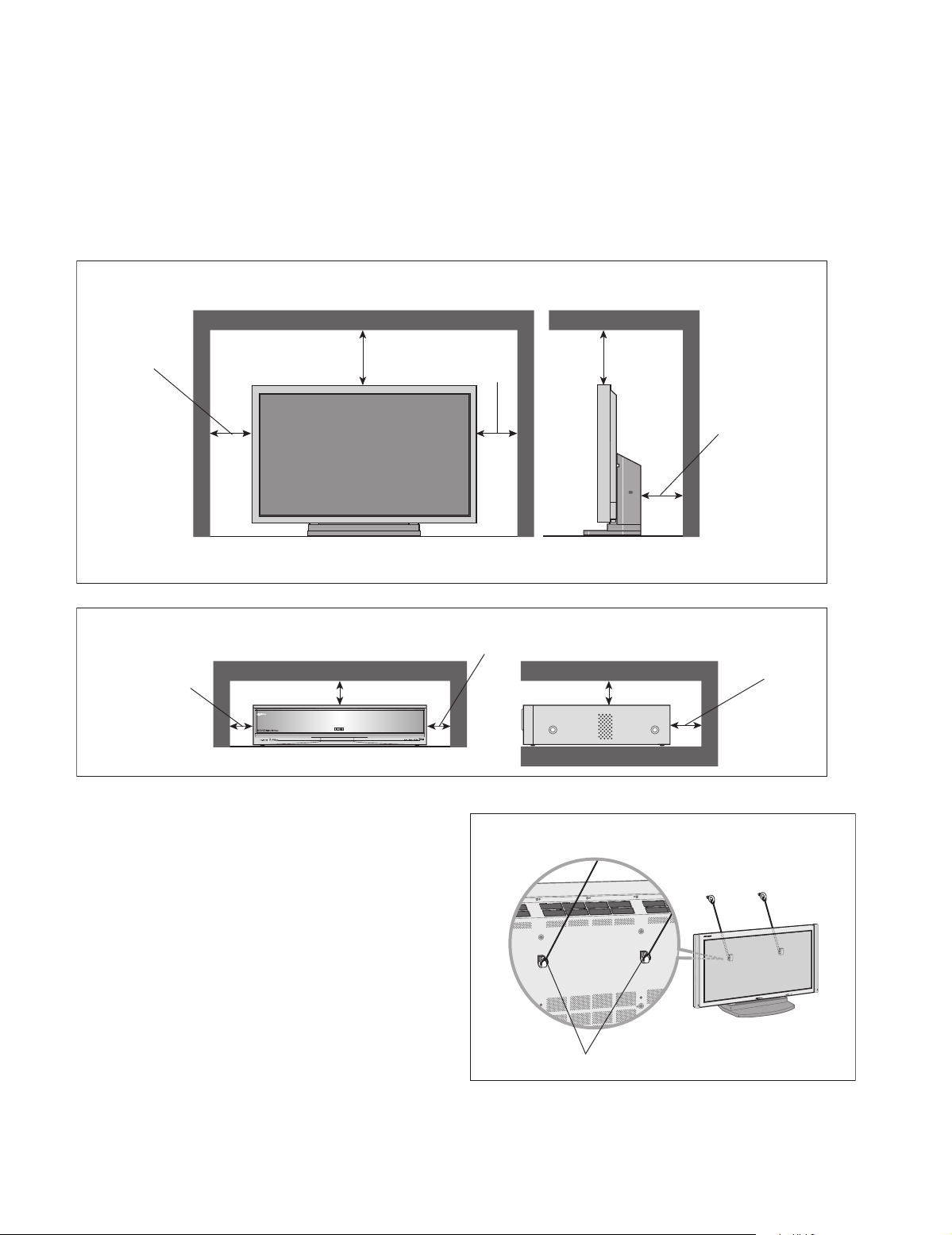
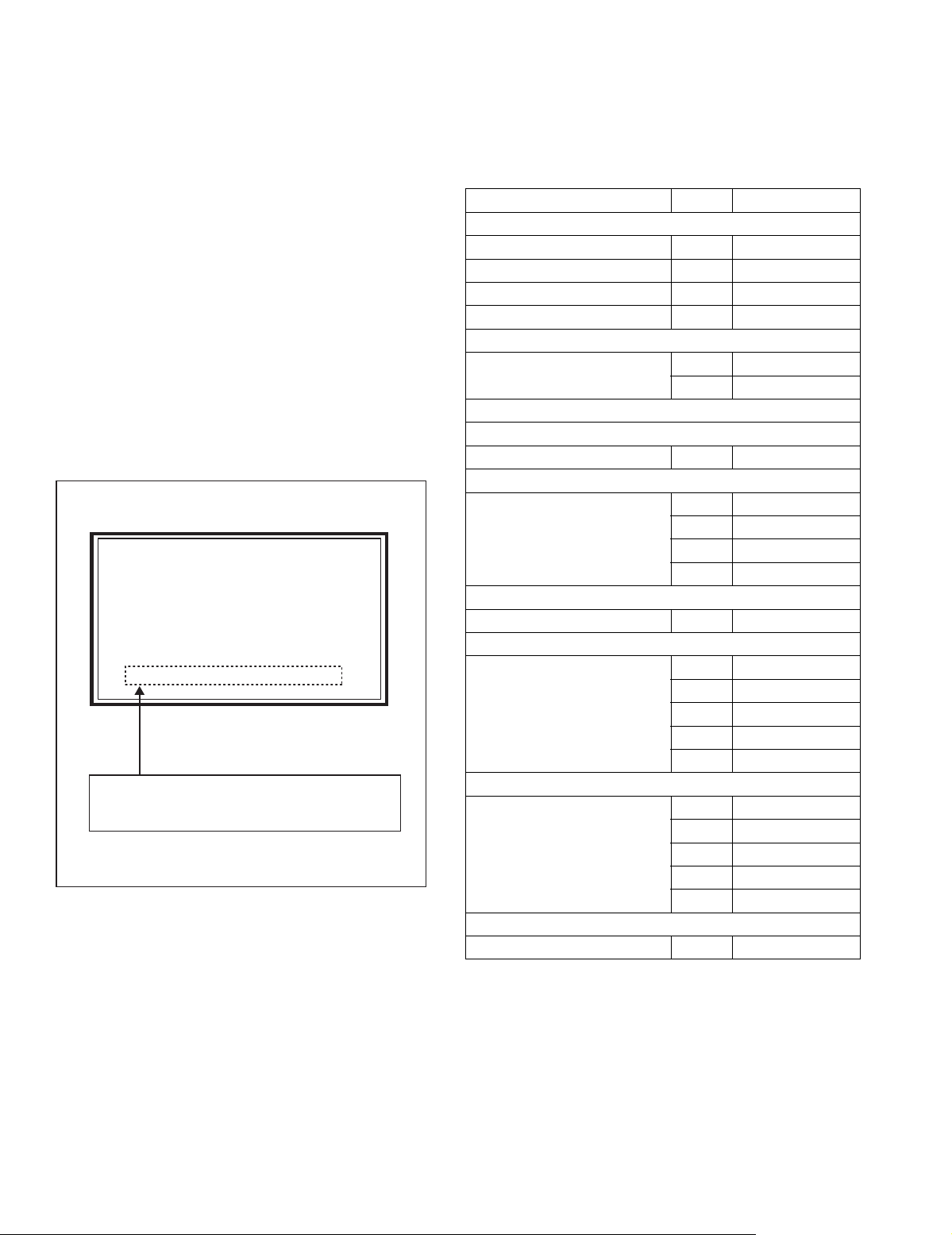
1.2 INSTALLATION
1.2.1 HEAT DISSIPATION
If the heat dissipation vent behind this unit is blocked, cooling
efficiency may deteriorate and temperature inside the unit will
rise. The temperature sensor that protects the unit will be
activated when internal temperature exceeds the pre-determined
level and power will be turned off automatically.
Therefore, please make sure pay attention not to block the heat
dissipation vent as well as the ventilation outlet behind the unit
and ensure that there is room for ventilation around it.
SPACE REQUIRED FOR INSTALLATION OF THE DISPLAY UNIT
1.2.2 INSTALLATION REQUIREMENTS
Ensure that the minimal distance is maintained, as specified
below, between the unit with and the surrounding walls, as well
as the floor etc.
Install the unit on stable flooring or stands.
Take precautionary measures to prevent the unit from tipping in
order to protect against accidents and earthquakes.
150mm or more
200mm or more
SPACE REQUIRED FOR INSTALLATION OF THE RECEIVER UNIT
100mm or more
㔚Ḯ
㔚Ḯ
Ꮐ㖸ჿฝ
Ꮐ㖸ჿฝ
ࡋ࠶࠼ࡎࡦ
ࡋ࠶࠼ࡎࡦ
5ᤋ
5ᤋ
ᤋ
ᤋ
ఝవ
ఝవ
ࡆ࠺ࠝജ
ࡆ࠺ࠝജ
)'/56 #4
1.2.3 FALL TIP PREVENTION MEASURES
Take precautionary measures to prevent the unit from falling or
tipping to protect against emergencies such as earthquakes as
well as accidents.
Fasten the supplied hook for tip fall prevention using the screws,
also supplied, behind the display unit, and use them together
with durable cords (to be purchased separately) to secure the
unit to a robust part such as the wall surface or pillars.
150mm
or more
100mm or more
200mm
or more
50mm or more
100mm or more
100mm or more100mm or more
1-4 (No.52108)
The supplied hook for tipfall prevention
Page 5

PD-42DXT
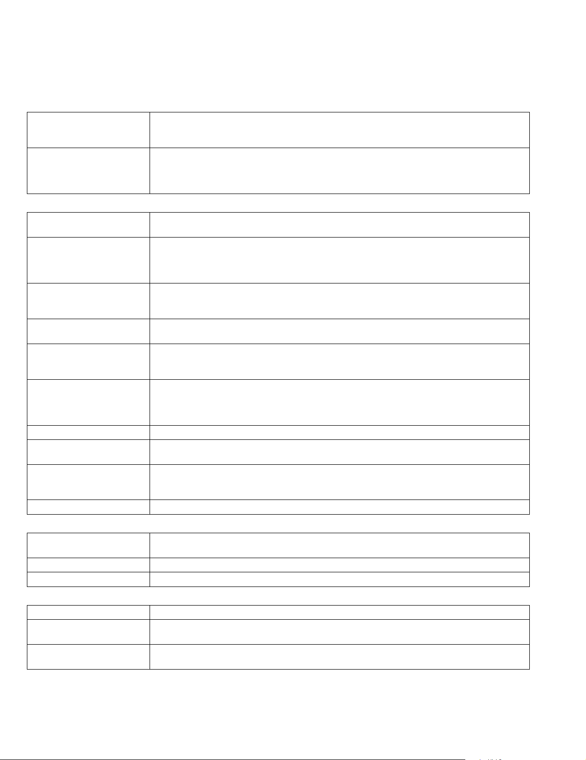
1.3 PRECAUTIONS DURING NOTES FOR TRANSPORTATION
When transporting the display unit, pressure exerted on the
internal PDP (Plasma Display Panel) due to improper handling
(such as tossing and dropping) may cause damages even when
the unit is carefully packed. To prevent accidents from occurring
during transportation, pay careful attention prior to delivery such
as through explaining the handling instructions to transporters.
Ensure that the following requirements are met during
transportation, as the PDP of this unit is made of glass and
therefore fragile:
(1) Avoid vibrations and impacts
The unit may be broken if it is toppled sideways even when
properly packed. Ensure that the unit is carried by at least
2 persons and pay careful attention not to exert any
vibration or impact on it.
(2) Do not place equipment horizontally
Ensure that it is placed upright and not horizontally during
transportation and storage as the PDP is very vulnerable to
lateral impacts and may break easily under such
circumstances.
During transportation, ensure that the unit is loaded along
the traveling direction of travel of the vehicle, and avoid
stacking them on one another.
For storage, ensure that they are stacked in 2 layers or less
even when placed upright.
1.4 RESIDUAL IMAGE / BURN-IN ON SCREEN
Like CRTs, ‘burn-ins’ may occur when a same image is
continuously displayed over an extended period of time.
As Tthis may also shorten the life span of the PDP. Therefore,
turn off the display when not in use, scroll the screen, make use
of screen-savers, or allow even distribution on the display by
inverting the brightness, switching to complementary colors or
inserting animated images at periodic intervals.
As burn-in is more likely to occur with high brightness and
contrast settings, try to use neutral gradations or medium tone
colors.
Burn-in does not occur in the case of animated images.
When switching to another image after continuous display of the
previous image, residual images may become prominent, as
luminance in a part of the display is higher than the other parts.
This is not a defect but is because due to the discharge surface
of the lighted portion has becomebeing relatively activated and
its luminance higher than the unlighted parts.
1.6 OPTICAL FILTER (PANEL FILTER)
Avoid placing the unit under direct sunlight over a prolonged
period of time. This may cause the optical filter to deteriorate in
quality and color.
Clean the filter surface by wiping it softly lightly with outing
flannels a soft and lightly fuzz cloth (such as flannel).
Do not use solvents such as benzine or thinner to wipe the filter
surface. This may cause the filter to deteriorate in quality or the
coating on the surface to come off.
As Tthe filter surface is fragile., Ddo not scratch or hit it with hard
materials.
1.7 NOTES PRECAUTIONS FOR REPLACEMENT OF EXTERIOR PARTS
Take note of the following when replacing exterior parts (back
REAR COVER, FRONT PANEL, optical filter):
Do not exert pressure on the front of the PDP (glass surface).
Pay careful attention not to scratch or stain the front of the PDP
(surface) with hands.
When replacing exterior parts, the front of the PDP should be
placed facing downward. Place a mat, etc. underneath to avoid
causing scratches to the front surface.
However, never use materials that are too soft (such as blanket
cloth). If replacement is made with the PDP surface facing
downward and in contact with the blanket, pressure may be
exerted on the PDP, thus causing damages to it.
1.5 INFRARED RAYS
Near Near-infrared rays (800nm to 1000nm) are emitted from the
front of the panel, and this may give rise to glitchescause
malfunctions in infrared remote controls or communication
systems placed near it. In this case, avoid direct infrared rays
(and reflected rays in some cases) from the screen by either
changing the direction of the unit or other infrared systems or
securing a longer keeping a distance from the screen.
(No.52108)1-5
Page 6
PD-42DXT
SECTION 2
SPECIFIC SERVICE INSTRUCTIONS
2.1 FEATURES
2.1.1 HIGH-DEFINITION IMAGE TECHNOLOGY (DET), HIGH QUALITY SOUND TECHNOLOGY (DD) EQUIPPED
DET (Digital Emotional Technology)
DD (Direct Drive) "Acoustic device that is accomplished through the interfacing of computer simulation and the acous-
2.1.2 MAIN FUNCTION
SD Memory Card Picture data and sound data recorded in the SD memory card can be play backed. In addition, view-
Auto power off function when
no signal is present / Prevention against forgetting to turn off
the TV.
Off Timer Setting for situations such as falling asleep while watching TV, and for prevention against forgetting
Digital E.E Sensor The brightness of the screen adjusts automatically in accordance with the brightness of the room. It
Memo screen function "The images that are currently seen can be viewed on the memo screen (still picture).
i. LINK Input/Output Terminal By just connecting an i. Link cable to the sharing device equipped with the i. Link terminal, interaction
D4 Input Terminal D-VHS and DVD supporting terminal.
Natural cinema function When viewing film-originated movie and animation, misty outline can be seen in fast moving images.
Program navigation function [Program navigation] screen is for the purpose of operating the functions of the electronic program
GR (Ghost reduction) Reduces ghost noise included in the ground-based broadcast.
Picture processing technology that changes various kinds of image signal, ranging from groundbased broadcast to D4 format of the digital satellite broadcast, to XGA high vision picture quality,
thereby accomplishing detailed high density images.
tic technology that we have developed over the years.
Attain wide and spontaneous acoustic field, real normal sound images that allows enjoyment of the
realistic sensation of reserved seats, from any audience seats."
ers can enjoy still picture from digital camera and music edited by computer.
The power supply of the TV will be cut off automatically when there is a continuous absence of signal
for 4 minutes, or when there is a maximum of 3 consecutive hours of no operation from user.
to turn off the TV. The power supply of the TV will be cut off automatically when the time exceeds
the set up timing (maximum 2 hours).
is a function that is power saving and gentle to eyes.
It is convenient for taking down notes like application address and recipe of cooking program etc,
while enjoying the current program."
of digital signal (referring to the image, sound & data broadcasting via satellite digital broadcast for
this unit) is possible. The interaction will not be affected even when the other devices are being disrupted.
Using natural cinema will enable viewing of clear images even in fast moving images.
guide. The program screen of the ground-based broadcast and digital satellite broadcast can be displayed when watching ground-based broadcast and digital satellite broadcast.
2.1.3 ASPECT CONTROL
Screen size switching Desired screen size (Auto panorama / Panorama / Closed caption panorama / Cinema / Full / Nor-
mal) can be selected.
Moving the screen up & down. Adjusts the vertical position of the screen.
Auto full mode Detects S1 signal and automatically goes to full mode.
2.1.4 MULTI-SCREEN FUNCTION
Dual-screen 2 programs an be viewed at the same time.
Program List (12 screens) All the programs that are being received are displayed at the same time. Desired program can be
selected from the 12 screens being displayed.
Different channel program
(4 screens)
1-6 (No.52108)
In addition to a current received program, three other programs are displayed at the same time.
Page 7
PD-42DXT
2.2 TECHNICAL INFORMATION
2.2.1 PDP STRUCTURE AND CHARACTERISTIC
This unit (Display Unit) uses the flat type panel PDP (Plasma Display Panel), instead of the conventional CRT (Cathode Ray Tube),
as a display unit.
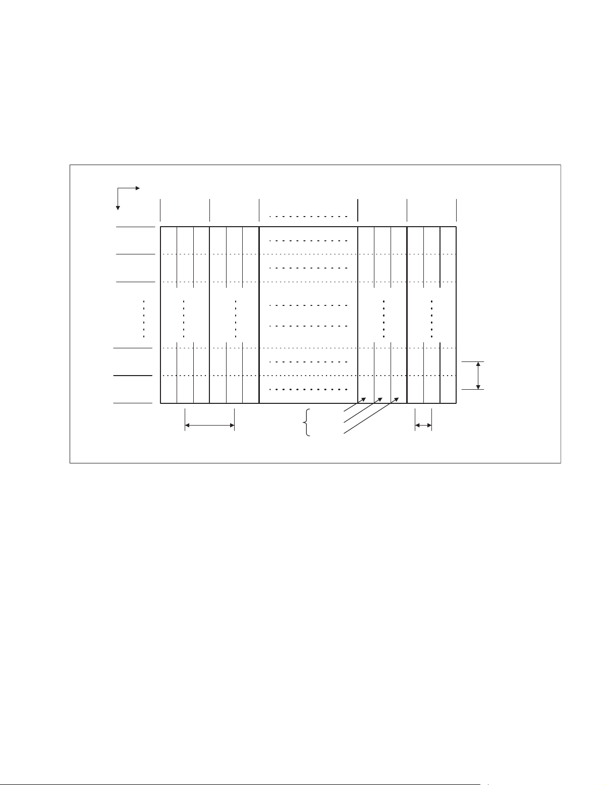
2.2.2 PIXEL (CELL) ARRAY
PDP is constructed by sealing the xenon, which emits neon and ultraviolet rays for discharging purpose, in between the electrodes
lay on the front glass substrate and rear glass substrate.
One pixel is composed of 3 RGB cells, with cell pitch of 0.299mm (1 pixel 0.897mm) horizontally and 0.675mm vertically.
The cell is arrayed in each RGB color as shown in Fig. 1. One pixel is formed by interlacing each RGB color cell.
One cell size is 0.299mm horizontally and 0.675mm vertically.
Direction
Vertically
2.2.3 PIXEL DEFECTS
Though PDP is made by means of ultra precise technology, there are cases whereby not all pixels (cell) will function properly. Pixel
defects, pixels that are always not lit, and on the contrary pixels that are always lit, exist depending on each case.
There are 2 types of Pixel defects, [Bright Dot Defects] and [Dark Dot Defects], as defined respectively in the following:
(1)Bright Dot Defects
Bright dot defects are pixel defects where the pixel should basically be unlit, but lit or blinks.
The presence of bright dot defects can be confirmed by inputting a full black signal (pattern).
(2)Dark Dot Defects
Black dot defects are pixel defects where the pixel should basically be lit, but does not lit, or is twice as bright when lit.
The presence of black dot defects can be confirmed by inputting a 100% full white signal (pattern).
Horizontally
No.1
Pixel line
No.2
Pixel line
No.767
Pixel line
No.768
Pixel line
No.1
Pixel
sequence
No.2
Pixel
sequence
R G B R G B
RG
R
R
BRGB
G BRG B
GBRGB
0.897mm(Horizontally)
Pixel pitch
sequence
R GBRG B
RGBRGB
R
R
R
1 pixel
(1 dot)
Fig.1 Alignment of pixel (cell)
G
B
Cell
Cell
Cell
No.1023
Pixel
No.1024
Pixel
sequence
G BRG B
GBRGB
0.299mm(Vertically)
Cell pitch
0.675mm
(Verticall)
Pixel pitch
(Cell pitch
(No.52108)1-7
Page 8

PD-42DXT
2.3 MAIN MI-COM FUNCTIONAL TABLE [RECEIVER UNIT]
Pin No. Terminal name Port name I/O Function
1 BS-RxD SBO0 O PDP communication port
2 /MICON_V /VSYNC I Vertical synchronizing signal input (For OSD)
3 LB_PRO P84 I Low B protection detect (In detection: H)
4 NC NC - Not used
5 /RST /RST I Reset jack (In resetting: L)
6 CONV.BUSY P52 IRQ4 I Not used
7 /TEST /TEST I 3.3V
8OSD_YS YS OY
signal output (For OSD)
S
9 /DPCRST P83 O Not used
10 BS/D P50 O In digital BS: L Other: H
11 A_MU P82 O Sound mute (TV) (In muting: H)
12 /MICON_H /HSYNC I Horizontal synchronizing signal input (For OSD)
13 M_MU P81 O Monitor output mute (In muting: H)
14 P46.OSDXI P46 OSDXI - Not used
15 P45.OSDXO P45 OSDXO - Not used
16 SDA2 P44 I/O Not used
17 AC_IN TM5IOB I AC power supply input
18 SCL2 P42 O Not used
19 TU_POW P41 O Tuner power control
20 VCOI VCOI I LPF input
21 PDO PDO O LPF output
22 /IP_RESET P80 O Reset (L)
23 OSD_YM DAYMOUT O Y
signal output (For OSD)
M
24 OSD_B DABOUT O B signal output (For OSD)
25 POW_LED P77 O Power supply LED (In lighting: H)
26 OSD_G DAGOUT O G signal output (For OSD)
27 OSD_R DAROUT O R signal output (For OSD)
28 VREF VREF I Not used
29 IP_ERR P76 I AMDP program load
30 IREF IREF I Not used
31 COMP COMP I Not used
32 AVDD AVDD I 3.3V
33 CLL CLL O Not used
34 VREFLS VREFLS I Standard voltage input (For SUB CCD)
35 SUB_CCD CVBS1 I Not used
36 NC NC - Not used
37 VSS VSS I GND
38 MAIN_CCD CVBS0 I Not used
39 VREFHS VREFHS I Standard voltage input (For CCD)
40 CLH CLH I Not used
41 VDD/VPP VDD(VPP) I 3.3V
42 CLKSW1 P75 O IP clock switch
43 CLKSW2 P74 O IP clock switch
44 ON_TIM P27 O Not used
45 PDP-Rx SBO1 O PDP communication
1-8 (No.52108)
Page 9

Pin No. Terminal name Port name I/O Function
46 PDP-Tx P25 SBD1 I PDP communication
47 SBT1 SBT1 I Port for writing on board
48 AP_DATA P23 I Auto panorama data input
49 BS-RESET P22 O Not used
50 SRQ P21 O Not used
51 BS1.5CTL P20 O Not used
52 /DVI_RST PWM2 O Not used
53 DVI_HP PWM1 O Connection detect (digital signal)
54 /MDR_CON PWM0 O Image control (PWM output)
55 /BS_POW P73 O Not used
56 BS_CLK_SEL P14 O Not used
57 TU2_AID ADIN8 I Not used
58 /LOB_POW P72 O LOB power control
59 /COMPULINK /IRQ3 I Not used
60 /POWERGOOD /IRQ2 I Power condition check
61 MECHA_SW P10•/IRQ1 I Discontinuation of mechanical swtich detection
62 /MAIN_POW P71 O Main power control
63 NC NC - Not used
64 /B1_POW P70 O Not used
65 C/N ADIN4 I Not used
66 XÅ|RAY ADIN3 I Not used
67 EE_CDS ADIN2 I EE sensor input
68 KEY2 ADIN1 I Key scan data input (KEY2)
69 KEY1 ADIN0 I Key scan data input (KEY1)
2
70 SCL1 SCL1 O I
71 SDA1 SDA1 I/O I
C bus clock (For EEPROM)
2
C bus data (For EEPROM)
72 REMO RMIN•/IRQ0 I Remote control data input
73 AP_REQ P87 O Auto panorama request
74 VSS VSS I GND
75 OSC2 OSC2 O 4MHz oscillation
76 OSC1 OSC1 I 4MHz oscillation
77 VDD VDD I 3.3V
2
78 SCL0 SCL0 O I
C bus clock (For wide use)
79 AP_CLK P86 O Auto panorama clock
2
80 SDA0 SDA0 I/O I
81 DVI_SDA P57SBT0 O I
C bus data (For wide use)
2
C bus data (digital signal)
82 BS_TXD(D_DATA) P56SBD0 I Not used
83 NC NC - Not used
84 P_MU P85 O Image mute control
PD-42DXT
(No.52108)1-9
Page 10
PD-42DXT
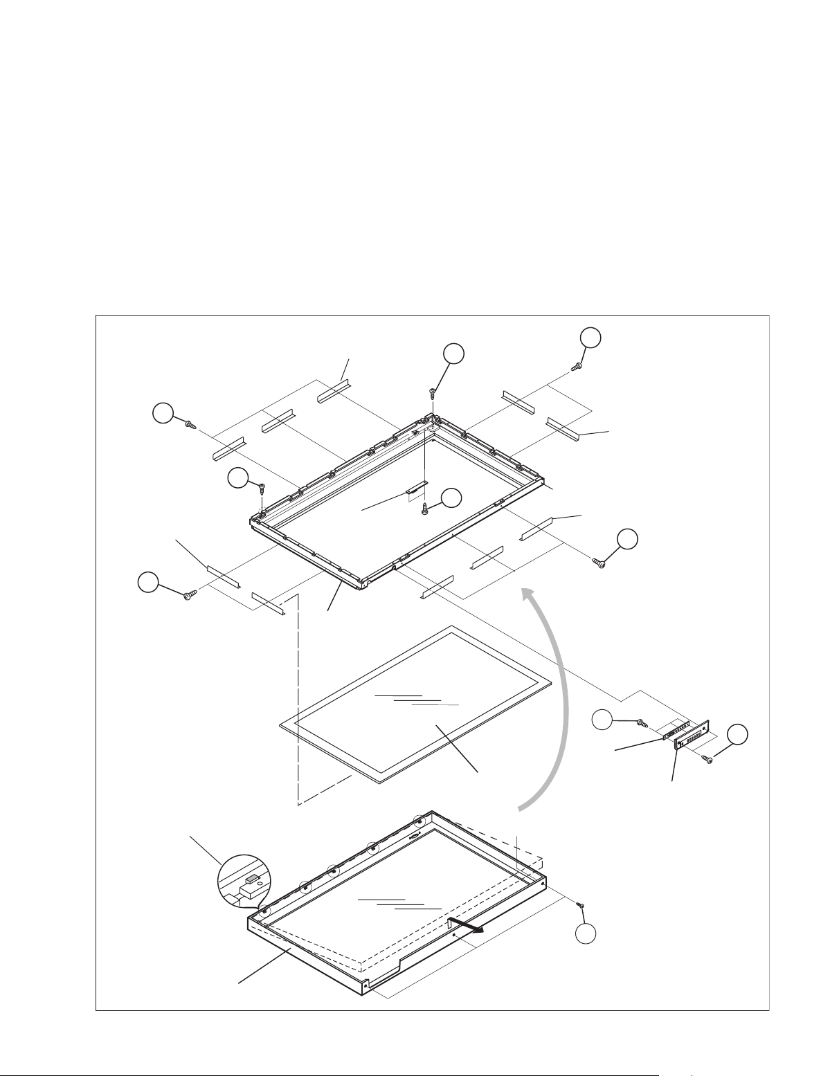
2.4 DISASSEMBLY PROCEDURE [DISPLAY UNIT]
Caution:
• When exchanging parts etc. with the front side (PDP side)
facing down, please place a protection sheet below before
starting, so as to prevent scratches on the front side.
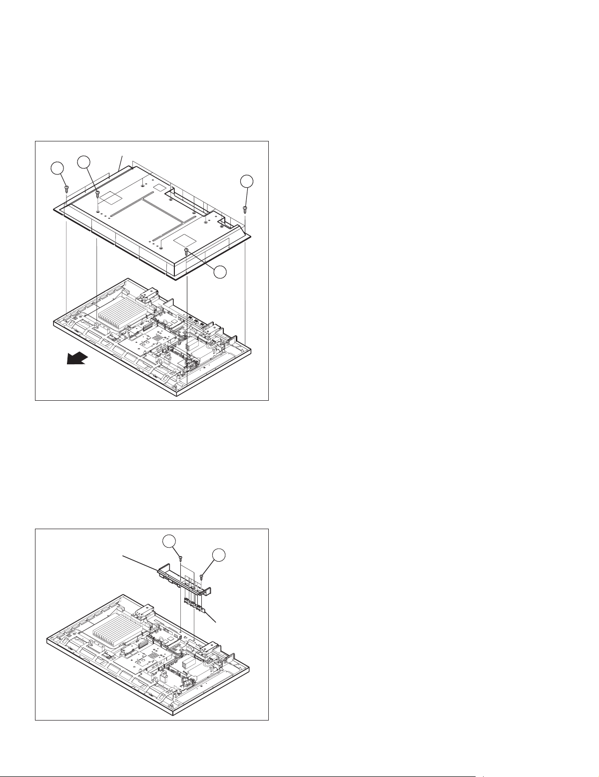
2.4.1 REMOVING THE REAR COVER (Fig.1)
(1) Remove the power cord / system cable / speaker cord.
(2) Remove the 19 screws [A] and the 6 screws [B].
REAR COVER
A
B
(x3)
B
(x3)
(x19)
2.4.3 REMOVING THE LINE FILTER PWB (Fig.3)
• Remove the REAR COVER.
• Remove the TERMINAL COVER.
(1) Remove the 6 screws [E], and remove the LINE FILTER
PWB together with the filter shield.
NOTE:
• Disconnect the connector [CN0PW] from the LINE
FILTER PWB.
• Disconnect the connector [CN900P] from the
SYSTEM POWER PWB.
A
• It is advisable to take note of the connecting location
(connector number) of the removed connectors.
2.4.4 REMOVING THE AUDIO PWB (Fig.3)
• Remove the REAR COVER.
• Remove the TERMINAL COVER.
(1) Remove the 4 screws [F], and remove the AUDIO PWB.
NOTE:
• Disconnect the connectors [CN60SP], [CN600K],
[CN60CA], [CN60CE], [CN60CF] from the AUDIO
PWB.
• It is advisable to take note of the connecting location
(connector number) of the removed connectors.
TOP
Fig.1
2.4.2 REMOVING THE TERMINAL COVER (Fig.2)
• Remove the REAR COVER.
(1) Remove the 2 screws [C], and withdraw the TERMINAL
COVER.
(2) Remove the 6 screws [D], and remove the SPEAKER
TERMINAL PWB.
NOTE:
• Disconnect the connector [CN60SP] from the
SPEAKER TERMINAL PWB.
C
TERMINAL COVER
(x2)
D
(x6)
SPEAKER
TERMINAL
PWB
2.4.5 REMOVING THE SYSTEM POWER PWB (Fig.3)
• Remove the REAR COVER.
• Remove the TERMINAL COVER.
(1) Remove the 4 screws [G], and remove the SYSTEM
POWER PWB.
NOTE:
• Disconnect the connectors [CN900J], [CN90CB],
[CN90CA], [CN900K] from the SYSTEM POWER
PWB.
• It is advisable to take note of the connecting location
(connector number) of the removed connectors.
2.4.6 REMOVING THE DISPLAY INTERFACE PWB (Fig.3)
• Remove the REAR COVER.
• Remove the TERMINAL COVER.
(1) Remove the 4 screws [H], and remove the DISPLAY
INTERFACE PWB.
NOTE:
• Disconnect the connectors [CN0AH], [CN0CB],
[CN0CD], [CN0CC], [CN0AV], [CN0CF], [CN0CE]
from the DISPLAY INTERFACE PWB.
• It is advisable to take note of the connecting location
(connector number) of the removed connectors.
2.4.7 REMOVING THE PDP POWER PWB (Fig.3)
• Remove the REAR COVER.
• Remove the TERMINAL COVER.
(1) Remove the 6 screws [ I ], and remove the PDP POWER
PWB.
NOTE:
• Disconnect the connectors [CN00J], [CN0AU],
[CN0AT], [CN0AV] from the PDP POWER PWB.
• It is advisable to take note of the connecting location
(connector number) of the removed connectors.
1-10 (No.52108)
Fig.2
Page 11
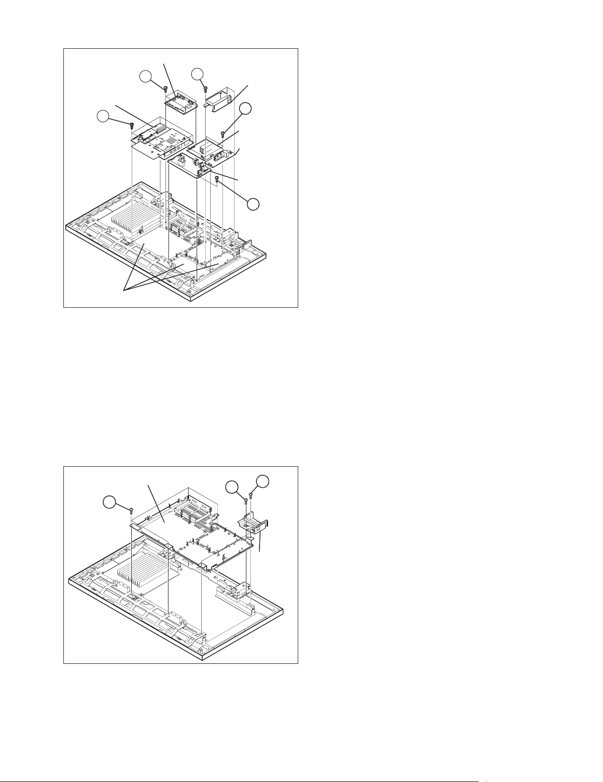
DISPLAY INTERFACE PWB
H
(x4)
PDP POWER PWB
I
(x6)
INSULATOR SHEET
(x6)
E
FILTER SHIELD
F
(x4)
AUDIO PWB
LINE FILTER
PWB
SYSTEM
POWER
PWB
G
(x4)
Fig.3
2.4.8 REMOVING THE CHASSIS BASE (Fig.4)
• Remove the REAR COVER.
• Remove the TERMINAL COVER.
• Remove the FILTER SHIELD and LINE FILTER PWB.
• Remove the AUDIO PWB.
• Remove the SYSTEM POWER PWB.
• Remove the DISPLAY INTERFACE PWB.
• Remove the PDP POWER PWB.
(1) Remove the 2 screws [J] and 1 screw [K].
(2) Lift upwards and withdraw the AC inlet in a front direction.
(3) Remove the 4 screws [L], and remove the CHASSIS
BASE.
PD-42DXT
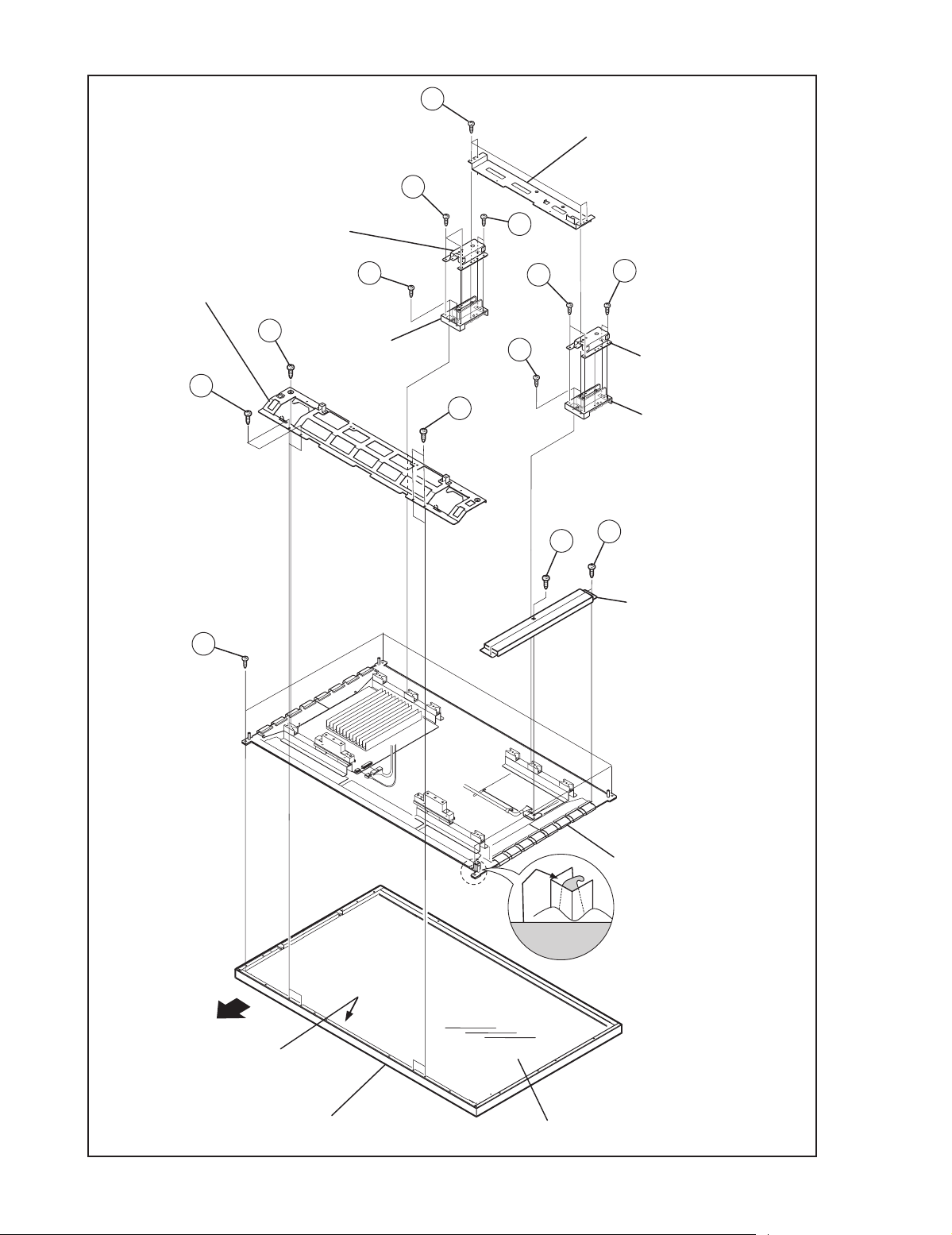
2.4.9 REMOVING THE PDP UNIT (Fig.5)
• Remove the REAR COVER.
• Remove the TERMINAL COVER.
• Remove the CHASSIS BASE (with each PWB affixed on the
CHASSIS BASE).
(1) Remove the 4 screws [M], and remove the terminal brack-
et.
(2) Disconnect the connectors of the following PWB.
NOTE:
• Disconnect the connector [CN0PW] from the LINE
FILTER PWB.
• Disconnect the connectors [CN0AU] and [CN0AT]
from the PDP POWER PWB.
• Disconnect the connector [CN0AH] and earth wire
from the DISPLAY INTERFACE PWB.
• It is advisable to take note of the connecting location
(connector number) of the removed connectors.
(3) Remove the 4 screws [N] and 5 screws [O], and remove
the 2 pieces of SUPPORT BRACKET (BOTTOM).
(4) Remove the 4 screws [P] and remove the 2 pieces of BACK
FRAME (BOTTOM).
(5) Remove the 4 screws [Q] and 1 screw [R], and remove the
2 pieces of SUPPORT BRACKET (UPPER).
(6) Remove the 2 screws [S] and 1 screw [T], and remove the
panel shield.
(7) Remove the 4 screws [U].
(8) Life the PDP upright and remove it with enough care not to
impose shock to the PDP.
Caution:
• Two or more people are required to remove the PDP
unit
• The gas pouring port is covered with the protection
material.In operation, be careful not to damage the gas
pouring port.
• Do not touch the front side (glass) of the PDP with your
fingers.
CHASSIS BASE
L
(x4)
Fig.4
K
J
(x2)
AC INLET
COVER
(No.52108)1-11
Page 12
PD-42DXT
N
M
(x4)
TERMINAL BRACKET
SUPPORT BRACKET
(BOTTOM)
SUPPORT BRACKET
(TOP)
BACK FRAME
R
(BOTTOM)
Q
(x2)
U
(x4)
(x2)
O
(x3)
N
(x2)
P
O
(x2)
P
(x2)
Q
(x2)
T
N
(x2)
SUPPORT BRACKET
(BOTTOM)
BACK FRAME (BOTTOM)
(x2)
S
(x2)
PANEL SHIELD
1-12 (No.52108)
TOP
INNER CASE
FRONT PANEL
Fig.5
GAS
insertion hole
FRONT FILTER
PDP UNIT
Page 13
PD-42DXT
2.4.10 REMOVING THE INNER CASE (Fig.6)
• Remove the REAR COVER.
• Remove the TERMINAL COVER.
• Remove the the CHASSIS BASE (with each PWB attached to
the CHASSIS BASE).
• Remove the PDP unit.
(1) Remove the 2 screws [V] and 3 screws [W].
(2) Lift the INNER CASE to about the height of the FRONT
PANEL frame, withdraw it in a front direction and remove it
from the 5 guiding bosses located at the top of the FRONT
PANEL.
Caution:
• The INNER CASE is attached with the filter (made of
glass). Be careful not to impose shock to it.
FILTER BRACKET
(x3)
a
(x3)
2.4.11 REMOVING THE DISPLAY LED PWB (Fig.6)
• Remove the INNER CASE.
(1) Remove the 2 screws [X], and remove the DISPLAY LED
PWB.
2.4.12 REMOVING THE PANEL SW PWB (Fig.6)
• Remove the INNER CASE.
(1) Remove the 2 screws [Y], and remove the CONTROL
BASE.
(2) Remove the 3 screws [Z], and remove the DISPLAY SW
PWB.
2.4.13 REMOVING THE FRONT FILTER (Fig.6)
• Remove the INNER CASE.
(1) Remove the 10 screws [a], and remove the 10 filter
brackets.
(2) Remove the FRONT FILTER with enough care not to
damage it.
a
V
(x2)
FILTER BRACKET
(x2)
FILTER BRACKET
(x2)
a
(x2)
BOSS
(x5)
V
#
FILTER BRACKET
(x3)
DISPLAY LED PWB
X
(x2)
a
(x3)
INNER CASE
Z
Y
(x2)
FRONT FILTER
#
(x3)
DISPLAY
SW PWB
CONTROL BASE
FRONT PANEL
W
(x3)
Fig.6
(No.52108)1-13
Page 14

PD-42DXT
2.5 DISASSEMBLY PROCEDURE [RECEIVER UNIT]
2.5.1 REMOVING THE TOP COVER
(1) Remove the 4 screws [A] on the both left and right sides.
(2) Remove the 3 screws [B] on the rear side.
(3) Lift upwards and withdraw the TOP COVER.
2.5.2 REMOVING THE FRONT PANEL
• Remove the TOP COVER.
(1) Remove the 1 screw [C], 2 screws [D] and 1 screw [E].
(2) Disengage the claw [F] on the bottom side.
(3) Disengage the claw [G] on the both left and right sides.
(4) Withdraw the FRONT PANEL in a front direction.
2.5.3 REMOVING THE DAMPER (INSIDE FRONT PANEL)
• Remove the TOP COVER.
• Remove the FRONT PANEL.
(1) Remove the 1 screw [H], and remove the DAMPER.
2.5.4 REMOVING THE FRONT CONTROL PWB
• Remove the TOP COVER.
• Remove the FRONT PANEL.
• Remove the DAMPER.
(1) Remove the 4 screws [I], and remove the FRONT CONTROL
PWB.
2.5.5 REMOVING THE REAR COVER
• Remove the TOP COVER.
(1) Remove the 2 screws [J], and withdraw the AC inlet.
(2) Remove the 1 screw [K], and withdraw the COOLNG FAN.
(3) Remove the 1 screw [L], and withdraw the BS HOLDER.
(4) Remove the 2 screws [M], and withdraw the bottom case.
(5) Remove the 2 screws [N] and 2 screws [O], and with draw
the display output terminal.
(6) Remove the 7 screws [P], and withdraw the video/audio
terminal.
(7) Withdraw the REAR COVER in a rear direction.
2.5.6 REMOVING THE DET MODULE PWB AND DET
RELAY PWB
• Remove the TOP COVER.
• Remove the FRONT PANEL.
• Remove the FRONT CONTROL PWB.
• Remove the REAR COVER.
(1) Remove the 2 screws [T], 2 screws [U], and 2 screws [V],
and lift upwards and withdraw the BS holder.
(2) Remove the 5 screws [W], pull down and withdraw the MI-
COM & DET MODULE PWB and DET RELAY PWB.
(3) Pulls right and left and remove the DET MODELE PWB
and DET RELAY PWB.
2.5.7 REMOVING THE RECEIVER POWER PWB AND MAIN PWB
• Remove the TOP COVER.
• Remove the FRONT PANEL.
• Remove the FRONT CONTROL PWB.
• Remove the REAR COVER.
• Remove the CHASSIS BRACKET.
• Remove the MI-COM & DET MODELE PWB and DET RELAY
PWB.
(1) Disengage the 2 connectors [b] attaching RECEIVER
POWER PWB and MAIN PWB.
(2) Remove the 6 screws [X], lift upwards and remove the
RECEIVER POWER PWB.
(3) Remove the 2 screws [Y] and 2 screws [Z], lift upwards and
remove the MAIN PWB.
2.5.8 REMOVING THE COOLING FAN
• Remove the TOP COVER
(1) Remove the 1 screw [K] and the 1 screw [a], lift upwards
and remove the COOLING FAN BRACKET.
(2) Pull the COOLING FAN in a direction of the arrow, and
remove the COOLING FAN.
1-14 (No.52108)
Page 15

TOP COVER
PD-42DXT
A
(x4)
A
CHASSIS BRACKET
Q
(x2)
C
FRONT PANEL
C
(x1)
FRONT PANEL
(BACK SIDE)
DAMPER
SD CARD PWB
SUB TUNER PWB
D
(x2)
I
(x4)
FRONT
CONTROL PWB
H
(x1)
Q
D
c
d
I
E
FRONT PANEL
T
(x2)
DET RELAY PWB
MAIN PWB
Y
(x2)
S
(x3)
G
Claw
S
BOTTOM CASE
B
(x3)
V
(x2)
U
(x2)
BS HOLDER
MI-COM & DET
MODULE PWB
H
W
(x5)
X
(x6)
CONNECTOR
RECEIVER POWER PWB
b
COOLING FAN
BRACKET
a
Z
(x2)
G
Z
Claw
b
COOLING
FAN
c
d
AC
INLET
a
J
(x2)
H
K
(x1)
FRONT
DOOR
F
HOOK
Fig.1
BACK COVER
P
(x7)
L
O
(x2)
N
(x2)
M
(x2)
(No.52108)1-15
Page 16
PD-42DXT
MAIN MENU SCREEN
SERVICEMAN SETTING MODE
2.6 REPLACEMENT OF MEMORY IC
This unit uses the nonvolatile memory IC.
The memory IC memories data for video and deflection circuits. To replace the memory IC without the data written, malfunctions might
occurred while power is on, and the normal image might not appear. When replacing the memory IC, be sure to use the IC written with
the initial values of data.
2.6.1 PROCEDURE FOR REPLACING THE MEMORY IC
(1) Switch the power off and unplug the power cord from the
wall outlet.
(2) Replacing the memory IC. [Be sure to use the IC written
with the initial values of data]
(3) Plug the power cord into the wall outlet and switch the
power on.
(4) Receive channel setting
(5) User setting
Memories the user setting items.
The [SETTINGS OF THE LAST MEMOLY FACTORY
SHIPMENT] setting is as next page.
(6) Serviceman setting mode
Check the serviceman setting items of setting mode in
Table 1, set if necessary.
For setting method, please refer to the [ADJUSTMENT
PREPARATION : ADJUSTMENT PROCEDURE] of AD-
JUSTMENT section.
1. PICTURE/SOUND (sound and picture setting)
Sound circuits (A) Fixed A01~A27
Video circuits (S) Adjust S01~S99
Deflection circuits (D) Fixed D01~D32
Factory setting items (F) Adjust F01~F59
2. YC SEP
3-dimensional YC separation
setting
3. WHITE BALANCE: cannot adjust
4. MEMORY SETUP: does not adjust
Memory data edit Fixed -
Setting Items Settings Item No.
Adjust YCM001~YCM185
Fixed YCS001~YCS114
5. DD/CM
MAIN MENU SCREEN
A setup of panel image processing
Adjust DDT01~DDT34
Fixed CMT01~CMT57
Fixed DDP01~DDP37
1. PICTURE/SOUND
2. YC SEP
3. WHITE BALANCE
4. MEMORY SETUP
5. DD/CM
6.
ߎߩࠝࡦࠬࠢࡦ␜ߪࡏ࠲ࡦࠍߐߥߢߐޕ
7. PANEL
8. PP
9. IP
10. GCR
Fixed CMP01~CMP03
7. PANEL: does not adjust
Panel power limit control Fixed PDA001~PDA012
8. PP
Multi-screen processing setting Adjust ADM001~ADM034
Fixed PPA001~PPA008
SERVICEMAN SETTING MODE
Fixed PPB001~PPB036
Fixed PPC001~PPC008
Fixed PPD001~PPD025
This is a message for users.
Ignore this message when in the Service Menu
mode.
9. IP
DET processing setting Fixed IPA001~IPA120
Fixed IPB001~IPB079
Fixed IPC001~IPC044
Fixed IPD001~IPD026
Fixed IPE001~IPE015
10. GCR
Ghost reduction setting Fixed GCR01~GCR08
1-16 (No.52108)
Serviceman setting items
Page 17
PD-42DXT
2.6.2 SETTINGS OF THE LAST MEMOLY FACTORY SHIPMENT
2.6.2.1 MAIN SIDE OPERATION (RECEIVER UNIT)
Switch Setting position
入力切換ボタン テレビ
チャンネルボタン 1
音量ボタン 適切な音量位置
画面サイズボタン ノーマル
2.6.2.2 REMOTE CONTROL SIDE OPERATION (LAST MEMORY)
Setting items Settings Setting items Settings
入力切換 テレビ サウンドモード スタンダード
チャンネル 1 画面サイズ ノーマル
音量 適切な音量位置 オフタイマー 切り(解除)
消音 切り 映像選択 スタンダード
画面表示 表示なし 映画 切り
機器ナビ 機器操作 ナチュラルシネマ オート
音声切換 モノラル
2.6.2.3 REMOTE CONTROL OPERATION MENU (1) PICTURE ADJUSTMENT
Customers can adjust the picture setting of menu screen as their own like but the picture standard value during factory shipment is as
below.
NTSC MODE
PICTURE MODE
ダイナミック
スタンダード
ゲーム
シアターステータス
シアタープロ DSD エッジ
ピクチャー
(PICTURE)
00 00 +12 00 00
00 00 00 00 00
-1000000000
00 00 00 00 00
00 00 00 00 00 00 00 00
黒レベル
(BRIGHT)
シャープネス
HV
色の濃さ
(COLOR)
DSD
コアリング
色あい
(TINT)
速度変調 白バラ赤 白バラ青 色バランス
シャープネス
(SHARP)
白バランス
(W.BALANCE)
高い色温度 切り
低い色温度 切り
高い色温度 切り
高い色温度 切り
ノイズクリア
(NOISE CLEAR)
HD MODE
PICTURE MODE
ダイナミック
スタンダード
ゲーム
シアターステータス
シアタープロ DSD エッジ
ピクチャー
(PICTURE)
+05000000+10
00 00 00 00 00 00
-1000000000
00 00 00 00 00
00 00 00 00 00 00 00 00
黒レベル
(BRIGHT)
シャープネス
HV
色の濃さ
(COLOR)
DSD
コアリング
色あい
(TINT)
速度変調 白バラ赤 白バラ青 色バランス
シャープネス
(SHARP)
白バランス
(W.BALANCE)
高い色温度 切り
低い色温度 切り
高い色温度 切り
低い色温度 切り
ノイズクリア
(NOISE CLEAR)
(No.52108)1-17
Page 18

PD-42DXT
(2) AUDIO ADJUSTMENT
Setting items Settings
高音 00
低音 00
BBE 入り
ステレオサウンド 切り
モノラルサウンド 切り
重低音 標準
左右バランス 00
(3) VARIOUS SETUP
Setting items Settings
画面サイズ ノーマル
映像選択 スタンダード
サウンドモード スタンダード
画面位置の調整 センター位置
デジタル E.E. 入り
デジタル E.E.. の効果表示
無信号電源オートオフ
S/N 連動 切り
テレビ消し忘れ防止設定
オートパノラマ動作時の画面 ノーマル画面
ビデオ 1 入力端子信号のモニター出力
AV コンピュリンクⅢ端子
Do not display
Do not set
Do not set
No output
Not use
(4) INITIAL SETTING
Setting items Settings
チャンネル・
入力設定の変更
CATV 選局方式の選択 12 ボタン方式
スクリーンセーバーの設定
画面シフト 標準
2.6.2.4 EACH POSITION REAL CH
Position
Real CH
見るチャンネル
画面の表示
+-ボタン 見る
GRT(ゴースト低減)入り
受像微調整 00
123456789101112
1143 416638842104612
Receiving remote control channel key
Displaying remote control channel key
Not set
1-18 (No.52108)
Page 19

2.7 REPLACEMENT OF CHIP COMPONENT
2.7.1 CAUTIONS
(1) Avoid heating for more than 3 seconds.
(2) Do not rub the electrodes and the resist parts of the pattern.
(3) When removing a chip part, melt the solder adequately.
(4) Do not reuse a chip part after removing it.
2.7.2 SOLDERING IRON
(1) Use a high insulation soldering iron with a thin pointed end of it.
(2) A 30w soldering iron is recommended for easily removing parts.
2.7.3 REPLACEMENT STEPS
1. How to remove Chip parts
[Resistors, capacitors, etc.]
(1) As shown in the figure, push the part with tweezers and
alternately melt the solder at each end.
PD-42DXT
2. How to install Chip parts
[Resistors, capacitors, etc.]
(1) Apply solder to the pattern as indicated in the figure.
(2) Grasp the chip part with tweezers and place it on the
solder. Then heat and melt the solder at both ends of the
chip part.
(2) Shift with the tweezers and remove the chip part.
[Transistors, diodes, variable resistors, etc.]
(1) Apply extra solder to each lead.
SOLDER
SOLDER
(2) As shown in the figure, push the part with tweezers and
alternately melt the solder at each lead. Shift and remove
the chip part.
NOTE :
After removing the part, remove remaining solder from the
pattern.
[Transistors, diodes, variable resistors, etc.]
(1) Apply solder to the pattern as indicated in the figure.
(2) Grasp the chip part with tweezers and place it on the
solder.
(3) First solder lead A as indicated in the figure.
A
B
C
(4) Then solder leads B and C.
A
B
C
(No.52108)1-19
Page 20

PD-42DXT
SECTION 3
ADJUSTMENTS
3.1 ADJUSTMENT PREPARATION
(1) Adjustment of many Majority of the adjustment items for
this unit is performed using the remote control.
(2) However, adjustment of some adjustment items is are
performed in the conventional way, i.e. with components
on the boards.
(3) Ensure that the power supply is AC110V.
(4) Allow the set and the measuring devices to run for at least
30 minutes.
(5) Do not alter settings of items/preset values on the service
screen that are not stated in this manual.
(6) Unless otherwise stated in the "Adjustment Procedure"
section, follow the settings for the features stated below
using the remote control:
Setting item Settings
映像選択 スタンダード
PICTURE ADJUSTMENT ITEMS 標準 (00)
画面サイズ ノーマル
SCREEN POSITION 標準 (00)
音声調節
白バランス 低い色温度
デジタル E.E
3.3 MAIN PARTS LOCATIONS (RECEIVER UNIT)
All center(00)
切り
3.2 MEASURING INSTRUMENT AND FIXTURES
• DC voltmeter (or Digital voltmeter)
• Oscilloscope
• Signal generator (Pattern generator)
• Remote control unit
SD CARD PWB
1-20 (No.52108)
SUB TUNER PWB
FRONT CONTROL PWB
a
MI-COM & DET MODULE PWB
DET RELAY PWB
MAIN PWB
RECEIVER POWER PWB
GR MODULE PWB
FRONT
a
Page 21

3.4 MAIN PARTS LOCATIONS (DISPLAY UNIT)
PD-42DXT
TOP
DISPLAY LED PWB
CN301
(PDP UNIT)
AU
CN302
(PDP UNIT)
AT
C4
CN0C4
PDP POWER PWB
AV
AV
C2
CF
NC
C1
CB CD CC
AH
CE
NC
SPEAKER TERMINAL PWB
DISPLAY INTERFACE PWB
J
SP
CHASSIS BASE
J
K
CA
CB
SYSTEM POWER PWB
P
K
P CA
CF
CE
L/F PWB
SP
CN104
(PDP UNIT)
AUDIO PWB
F901
PW
SPEAKER TERMINAL
POWER CONNECTOR
DISPLAY SW PWB
(No.52108)1-21
Page 22

PD-42DXT
***
****
The following items are basically adjustment items.
However, do not make adjustments if the range item is
not specified in the "ADJUSTMENT PROCEDURE" section.
***
***
***
***
***
***
***
***
***
***
****
****
**
**
***
***
***
***
***
***
***
***
***
The following items are basically adjustment items.
However, do not make adjustments if the range item is not
specified in the "ADJUSTMENT PROCEDURE" section.
3.5 SERVICE MENU SCREEN
MAIN MENU
1.PICTURE/SOUND 7.PANEL
2.YC SEP 8.PP
3.WHITE BALANCE 9.IP
4.MEMORY SETUP 10.GCR
5.DD/CM
6.
ߎߩࠝࡦࠬࠢࡦ␜ߪࡏ࠲ࡦࠍߐߥߢߐޕ
The following items are basically adjustment items.
However, do not make adjustments if the range item is not
specified in the "ADJUSTMENT PROCEDURE" section.
1.PICTURE/SOUND
Control using the
Volume (+/-) key
A01㨪A27
S01㨪S99
D01㨪D32
F01㨪F59
Control using the
Channel (+/-) key
NTSC FULL ST L FL MUTE
A01
***
The following items are basically adjustment items.
However, do not make adjustments if the range item is
not specified in the "ADJUSTMENT PROCEDURE" section.
2.YC SEP
NTSC FULL ST L FL MUTE
YCM001
001
3.WHITE BALANCE
BR
***
DRV R
CUT R
***
***
***
B
G
***
***
B
***
YCM001㨪YCM185
YCS001
㨪
YCS114
IPA001㨪IPA120
IPB001㨪IPB079
IPC001㨪IPC044
IPD001㨪IPD026
IPE001㨪IPE025
S01
D01
F01
9. IP
NTSC FULL ST L FL MUTE
IPA001
****
001
***
***
***
4. MEMORY SETUP
ࠕ࠼ࠬ*
㧜 㧝 㧞 㧟 㧠 㧡 㧢 㧣
******************************
㧤 㧥 㧭 㧮 㧯 㧰 㧱 㧲
******************************
NTSC FULL ST L FL MUTE
DDTO1
001
PDA001
IN
***
APL
***
****
5.DD/CM
***
7. PANEL
***
OUT
***
MIN
***
TEM
MAX
DDT01㨪DDT34
CMT01㨪CMT57
DDP01㨪DDP37
CMP01㨪CMP03
PDA001㨪PDA012
***
***
1-22 (No.52108)
GCR01㨪GCR08
10. GCR
NTSC FULL ST L FL MUTE
GCR01
****
00001000
NTSC FULL ST L FL MUTE
ADM001
***
8. PP
ADM001㨪ADM034
PPA001㨪PPA008
PPB001㨪PPB036
PPC001㨪PPC008
PPD001㨪PPD025
Page 23

3.6 BASIC OPERATION OF THE SERVICE MENU MODE [USING REMOTE CONTROL]
MAIN MENU
SERVICEMAN SETTING MODE
3.6.1 HOW TO ENTER THE SERVICE MENU MODE
NOTE:
Ensure that the cursor (arrow) of the User Menu screen is
pointing at Picture Control.
(1) Set to 30 minutes using the [ オフタイマー ] key.
(2) Press the [ メニュー ] key.
(This key is also used to exit the Service Menu mode.)
(3) Enter the Service Menu mode by pressing the [12] key.
(4) When the Main Menu is displayed, press any key of the [1]
to [10] key to enter the corresponding menu mode.
1. PICTURE/SOUND
2. YC SEP
3. WHITE BALANCE
4. MEMORY SETUP
5. DD/CM
6.
*Press any of the [1] to [10] keys before the Service Menu
mode disappears.
ߎߩࠝࡦࠬࠢࡦ␜ߪࡏ࠲ࡦࠍߐߥߢߐޕ
(5) Select the service item using the [チャンネル (+/-)] key and
[Dual Sound] keys.
(6) Set the value using the [ 音量 (+/-)] key.
SERVICEMAN SETTING MODE
(7) Press the [ 消音 ] key to save the value.
NOTE:
Ensure that the items are set as follows before entering the
Service Menu mode:
オートパノラマ 使用しない
This is a message for users.
Ignore this message when in the Service Menu
mode.
映画ボタン 切
USER MENU SCREEN 映像調節
3.6.2 HOW TO EXIT THE SERVICE MENU MODE
Press the [ メニュー ] key to exit the Service Menu mode.
3.6.3 SERVICE CONTROL KEY LAYOUT ON THE REMOTE CONTROL
PD-42DXT
MAIN MENU
7. PANEL
8. PP
9. IP
10. GCR
࠴ࡖࡦࡀ࡞
(㧗/㧙)
ࡔࡕ↹㕙
ࠨࡆࠬಾ឵
ࠫࠝ
࠹ࡆ
࠺࠲ ജಾ឵
0*- 0*- 0*-J
1 2 3
$5ᣣ࠹ $5ᦺᣣ $5K
4 5 6
$5, $5ࡈࠫ 919
7 8 9
10 11 12
$5 %5 %5
࠴ࡖࡦࡀ࡞
ᶖ㖸
㔚Ḯ
ᶖ㖸
[1]㨪[10]
ࠬ࠲
0㧖
[12]
ㆬዪ
↹㕙␜⇟ภജ
ࡔ࠾ࡘ
㖸㊂
ᯏེ࠽ࡆ
ࡔ࠾ࡘ
రߩ↹㕙
⇟⚵࠽ࡆ
⇟⚵
⇟⚵⺑
ቯ
ࡔ࠾ࡘ
ࡎࡓ
ଢᯏ⢻
⇟⚵࠭ࡓ
ᚯࠆ
CURSOR KEY
(㧗/㧙)
㖸㊂
ᶖ㖸
೨ᣣ ⠉ᣣ %/
࠺࠲ㅍ
ࠨ࠙ࡦ࠼
ࡕ࠼
㖸ჿಾ឵
ᤋಾ឵
ࠝࡈ࠲ࠗࡑ
ᤋㆬᛯ
ᤋ↹
↹㕙ࠨࠗ࠭
ࡑ࡞࠴↹㕙
࠽࠴ࡘ࡞ࠪࡀࡑ
㖸ჿಾ឵
ࠝࡈ࠲ࠗࡑ
<The state which opend the lid>
(No.52108)1-23
Page 24

PD-42DXT
3.6.4 SETTINGS OF THE SERVICE MENUS
3.6.4.1 [1. PICTURE/SOUND (Picture/sound setting)]
Adjusts output data to ports such as sound, deflection, signal and
others (Item F):
(1) SIGNAL TYPE
The signal currently displayed on the screen is displayed.
NTSC : NTSC (525i = S/Composite)
DVD : 525i (Component)
ED : 525p
HD : 1125i
750p : 750p
(2) SCREEN SIZE
FULL : フル
PANO : パノラマ
JIPA : 字幕パノラマ
CINE : シネマ
REGU : ノーマル
At multi screen mode
M1 : 1 Single screen (For adjustment)
M2-1 : 2 Dual screens (4:3)
M2-2 : 2 Dual screens (16:9)
M4 : 4 Four screens (Other program)
M12 : 12 Twelve screens (List of programs)
(3) PICTURE SELECTION
Displays current picture selection mode:
ST : スタンダード
DA : ダイナミック
TH : シアター
GA : ゲーム
(4) WHITE BALANCE
Displays white balance setting item in the picture selection
mode:
H: 高い色温度
L: 低い色温度
(5) SERVICE ITEM CODES
Displays corresponding codes for A: Sound, S: Signal, D:
Deflection and F: Factory Settings.
<Settings of Service Item>
•[チャンネル (+/-)] key
For scrolling up/ down the item codes.
A01 S01 D01 F01
•[音声切換 ] key
For switching to the next item.
A01 S01 D01 F01
(6) VALUE SETTING (DATA)
Specify values for each of the items in sequence.
•[音量 (+/-)] key
For selecting the value (data) of each item by scrolling
up/down the key.
•[消音 ] key
For saving the entered values (data).
(7) DATA SAVING METHOD
Displays the method for saving the entered values (data).
MUTE : To save data using the [ 消音 ] key
DIR : To save data instantly upon alteration
(8) I-P interpolation MODE
Not required in servicing.
FL : FLAME
LI : LINE
(2) Screen Size
(1) Signal Type
NTSC FULL ST L FL MUTE
A01
(3) Picture Selection
(8) I-P interpolation MODE
***
(4) White Balance
(7) Data Saving Method
(6) Value Setting(Data)(5) Service Item Codes
NOTE:
Setting for any of the following items that is not included in the
“ADJUSTMENT PROCEDURE” section found in the later part
of this manual will not be performed in servicing.
3.6.4.2 [2. YC SEP (3-D Y/C Separation setting)]
<Do not change settings of items that are not included in the
"ADJUSTMENT PROCEDURE" section.>
Sets output data to the 3-D Y/C separation circuit.
•[チャンネル (+/-)] key
For scrolling up/down the item codes.
•[音量 (+/-)] key
For scrolling up/down the data values.
3.6.4.3 [3. WHITE BALANCE (White Balance setting)]
Setting for this item is not required in servicing.
3.6.4.4 [4. MEMORY SETUP (Memory setting)]
[Do not change settings]
3.6.4.5 [5. DD/CM]
<Do not change settings of items that are not included in the
"ADJUSTMENT PROCEDURE" section.>
•[チャンネル (+/-)] key
For scrolling up/down the item codes.
•[音量 (+/-)] key
For scrolling up/down the data values.
3.6.4.6 [7. PANEL]
[Do not change settings]
3.6.4.7 [8. PP (Multi-screen Processing setting)]
<Do not change settings of items that are not included in the
"ADJUSTMENT PROCEDURE" section.>
Sets output data to the multi-screen processing circuit.
•[チャンネル (+/-)] key
For scrolling up/down the item codes.
•[音量 (+/-)] key
For scrolling up/down the data values.
3.6.4.8 [9. IP (DET setting)]
[Do not change settings]
Sets output data to the DET circuit.
3.6.4.9 [10. GCR (Ghost reduction setting)]
[Do not change settings]
Sets output data to the ghost reduction circuit
1-24 (No.52108)
Page 25

PD-42DXT
3.7 DEFAULT VALUES IN THE SERVICEMAN PERSONNEL SETTING MODE
• Perform fine-tuning based on the "default values" using the remote control when in the Service Personnelman Setting mode.
• The "default values" serve only as an indication rough standard and therefore the values with which optimal display can be achieved
may be different from the default values. But, don't change the values that are not written in "3.8 ADJUSTMENT". They are fixed
values.
NOTE:
As for the items whose settings are "Fixed" in Table 1 in "2.6 REPLACEMENT OF MEMORY IC", the following tables show initial
values in NTSC signal input mode . As for the items whose conditions of SETTING VALUE are not written in the following tables,
the following tables show initial values in NTSC signal input mode .
• Among the default values, there are some that are displayed "( )"as offset values.
These are values relative to the base or absolute values. Set the values by adding offset values to the base values.
Base values are displayed as "---".
3.7.1 <1.PICTURE/SOUND>
Item
No.
A01 (NO DISPLAY) 000~007 003
A02 (NO DISPLAY) 000~007 003
A03 (NO DISPLAY) 000~007 003
A04 (NO DISPLAY) 000~007 004
A05 (NO DISPLAY) 000~015 009
A06 (NO DISPLAY) 000~015 006
A07 (NO DISPLAY) 000~015 006
A08 (NO DISPLAY) 000~015 003
A09 (NO DISPLAY) 000~007 006
A10 (NO DISPLAY) 000~007 004
A11 (NO DISPLAY) 000~063 063
A12 (NO DISPLAY) 000~063 063
A13 (NO DISPLAY) 000~003 000
A14 (NO DISPLAY) 000~007 000
A15 (NO DISPLAY) 000~003 000
A16 (NO DISPLAY) 000~003 000
A17 (NO DISPLAY) 000~003 000
Item Variable range Setting value
Item
No.
S01 COLOR 000~255 145 130 140 130 140 130 150 140
S02 TINAD -127~128 000 000 000 000 000 000 000 000
S03 OF COLOR -127~128 (---) (---) (---) (---) (---) (---) (---) (---)
S04 OF TINAD -127~128 (---) (---) (---) (---) (---) (---) (---) (---)
Item
No.
S05 BRIG 000~255 128 128 048 041 046 039 045 041
S06 CONT 000~255 128 128 128 128 128 128 128 128
S07 OF BRIG -127~128 (---) (---) (---) (---) (---) (---) (---) (---)
S08 OF CONT -127~128 (---) (---) (---) (---) (---) (---) (---) (---)
Item Variable range
Item Variable range
NTSC 525i 525p 750p/1125i
スタンダード
スタンダード
シアター
2画面 OTHERS
シアター
スタンダード
NTSC
スタンダード
Setting value
シアター
Setting value
シアター
スタンダード
スタンダード
シアター
525i/525p 750p/1125i
シアター
スタンダード
スタンダード
シアター
シアター
(No.52108)1-25
Page 26

PD-42DXT
Item
No.
S09 BYGN 000~255 118 130 123 130 128 130 118 120
S10 OF BYGN -127~128 (---) (---) (---) (---) (---) (---) (---) (---)
S11
S12 MTX 000~003 000 000 000 000 000 000 001 001
Item
No.
S13 RDRV 000~255 255 255 255 255 255 255 255 255
S14 RDRV -127~128 (-028) 000 000 000 (-028) 000 000 000
S15 GDRV 000~255 255 255 005 255 255 255 255 255
S16 GDRV -127~128 (-016) 000 (-003) (-016) (-016) 000 (-003) (-016)
S17 BDRV 000~255 255 255 255 255 255 255 255 255
S18 BDRV -127~128 000 000 (-017) (-032) 000 000 (-017) (-032)
Item
No.
S13 RDRV 000~255 255 255 255 255 255 255 255 255
S14 RDRV -127~128 (-028) 000 000 000 (-028) 000 000 000
S15 GDRV 000~255 255 255 255 255 255 255 255 255
S16 GDRV -127~128 (-016) 000 (-003) (-016) (-016) 000 (-003) (-016)
S17 BDRV 000~255 255 255 255 255 255 255 255 255
S18 BDRV -127~128 000 000 (-017) (-032) 000 000 (-017) (-032)
Item Variable range
RYAXIS
Item Variable range
Item Variable range
-127~128 +006 000 +006 000 +006 000 000 000
NTSC 525i 525p 750p/1125i
スタンダード
スタンダード シアター スタンダード シアター
高低高低高低高低
スタンダード シアター スタンダード シアター
高低高低高低高低
シアター
スタンダード
NTSC 525i
525p 750p/1125i
Setting value
シアター
Setting value
Setting value
スタンダード
シアター
スタンダード
シアター
Item
No.
S19 CUTR 000~255 128 128 128 128 128 128 128 128
S20 OF CUTR -127~128 000 000 000 000 000 000 000 000
S21 CUTG 000~255 123 123 123 123 123 123 123 123
S22 OF CUTG -127~128 000 000 000 000 000 000 000 000
S23 CUTB 000~255 125 125 125 125 125 125 125 125
S24 OF CUTB -127~128 000 000 000 000 000 000 000 000
S25 CUTR 000~001 000 000 000 000 000 000 000 000
S26 CUTG 000~001 000 000 000 000 000 000 000 000
S27 CUTB 000~001 000 000 000 000 000 000 000 000
1-26 (No.52108)
Item Variable range
NTSC 525i 525p 750p/1125i
スタンダード
シアター
スタンダード
Setting value
シアター
スタンダード
シアター
スタンダード
シアター
Page 27

PD-42DXT
Item
No.
S28 BTHN 000~001 001 000 001 000 001 000 001 001
S29 BCALM 000~001 000 000 000 000 000 000 000 000
S30 BKAKOU 000~031 008 012 007 000 007 000 002 012
S31 BLIM 000~063 016 006 010 000 010 000 016 006
S32 BSTPO 000~063 048 050 040 063 040 063 048 050
S33 BKAKON 000~001 001 001 001 001 001 001 001 001
S34 WTHN 000~001 001 001 001 001 001 001 001 001
S35 WCALM 000~001 000 000 000 000 000 000 000 000
S36 WKAKOU 000~031 000 000 000 000 000 000 000 000
S37 WLIM 000~255 200 220 220 213 220 213 225 220
S38 WSTPO 000~063 050 050 054 036 054 036 018 050
S39 WPEAK 000~063 060 060 063 063 063 063 060 060
S40 WKAKON 000~001 001 001 001 001 001 001 000 001
S41 WGAINC 000~001 000 001 001 001 001 001 000 001
S42 GAINB 000~003 001 000 003 000 003 000 001 000
S43 SLIC 000~031 011 011 013 019 013 019 011 011
S44 APG 000~003 001 002 001 003 001 003 001 002
S45 GAINA 000~003 001 001 001 001 001 001 002 001
Item Variable range
NTSC 525i 525p 750p/1125i
スタンダード
シアター
スタンダード
Setting value
シアター
スタンダード
シアター
スタンダード
シアター
Item
No.
S46 (NOT USED) 000~015 015 015
S47 (NOT USED) 000~015 015 015
Item
No.
S48 DCTRAN 000~015 015 015 015 015 015 015
Item
No.
S49 HSTR 000~001 000 000 000
S50 HSTR 000~255 010 018 010
S51 HEND 000~001 000 000 000
S52 HEND 000~255 087 079 087
S53 VSTR 000~001 000 000 000
S54 VSTR 000~255 016 006 006
S55 VEND 000~001 000 000 000
S56 VEND 000~255 082 092 092
S57 BHSTR 000~255 000 000 000
S58 BHSTR 000~015 000 000 000
S59 BHEND 000~255 013 013 013
S60 BHEND 000~015 000 000 000
Item Variable range
Item Variable range
Item Variable range
Setting value
スタンダード
スタンダード
シアター
Setting value
NTSC 525i/525p 750p/1125i
シアター
2 画面 ノーマル OTHERS
スタンダード
Setting value
シアター
スタンダード
シアター
NOTE:
Data of the setting value is selected in the order of "2画面", " ノーマル ", and "OTHERS".
(No.52108)1-27
Page 28

PD-42DXT
Item
No.
S61 PLPOL2 000~001 001 001 001 001 001 001
S62 PLEV2 000~127 016 015 016 015 016 015
S63 PLPOL1 000~001 000 000 000 000 000 000
S64 PLEV1 000~127 000 000 000 000 000 000
Item
No.
S65 MODC 000~003 002 002 002 002 002 002 002 002
S66 RMC 000~003 003 003 003 003 001 003 003 003
S67 RGA 000~003 002 002 002 002 002 003 003 003
S68 CLIP 000~015 000 000 000 000 000 000 000 000
S69 COR 000~063 019 019 019 019 019 019 019 019
Item
No.
S70 TINTON 001~001 001
S71 DRIVER 001~255 255
S72 DRIVEG 001~255 255
S73 DRIVEB 001~255 255
Item Variable range
Item Variable range
Item Variable range Setting value
NTSC 525i/525p 750p/1125i
スタンダード
スタンダード
シアター
2画面 OTHERS
シアター
NTSC
Setting value
スタンダード
スタンダード
シアター
Setting value
シアター
スタンダード
スタンダード
シアター
525i/525p 750p/1125i
シアター
スタンダード
シアター
Item
No.
S74 EECONT 001~031 018
S75 EEBRT 001~031 031
Item
No.
S76 EETBRT -127~128 000 000 000
S77 EETCONT -127~128 000 000 000
Item
No.
S78 PICMAX 001~255 255 255
S79 PICMIN 001~255 000 000
S80 BRTMAX 001~255 255 255
S81 BRTMIN 001~255 000 000
S82 COLMAX 001~255 255 255
S83 COLMIN 001~255 000 000
Item
No.
S84 TEST 001~015 000
S85 BTL 001~255 000
S86 GTL 001~255 000
Item Variable range Setting value
Item Variable range
Item Variable range
Item Variable range Setting value
NTSC 525i/525p 750/1125i
Setting value
スタンダード
シアター
Setting value
1-28 (No.52108)
Page 29

PD-42DXT
Item
No.
S87 GM 001~003 002 001 001
Item
No.
S88 APLGAIN 001~007 007 007 007 007 007 007 007 007
S89 APLLIM 001~255 030 030 030 030 030 030 030 030
S90 ABSGAIN 001~127 000 000 000 000 000 000 000 000
S91 BLKGAIN 001~007 007 007 007 007 007 007 007 007
S92 BLKLIM 001~031 031 031 031 031 031 031 031 031
S93 WHTGAIN 001~007 007 007 007 007 007 007 007 007
S94 WHTLIM 001~031 031 031 031 031 031 031 031 031
S95 DCSTART 001~255 060 060 055 060 055 060 060 060
S96 DCGAIN 001~015 008 006 010 008 010 008 008 006
S97 DCLIM 001~063 030 025 030 025 030 025 025 025
S98
S99
Item
No.
F01 (NO DISPLAY) 000~255 000
F02 (NO DISPLAY) 000~255 000
F03 (NO DISPLAY) 000~255 000
F04 (NO DISPLAY) 000~255 032
F05 (NO DISPLAY) 000~001 000
F06 CATVMAX 000~001 001
F07 (NO DISPLAY) 000~255 150
F08 (NO DISPLAY) 000~255 051
Item Variable range
Item Variable range
(NO DISPLAY)
(NO DISPLAY)
Item Variable range Setting value
001~001 000 000 000 000 000 000 000 000
001~001 000 000 000 000 000 000 000 000
ダイナミック
スタンダード
NTSC 525i 525p 750p/1125i
シアター
Setting value
スタンダード
スタンダード
/ ゲーム シアター
Setting value
シアター
スタンダード
シアター
スタンダード
シアター
Item
No.
F09 AUTOSCR1 000~015 001 002
F10 AUTOSCR2 000~015 002 004
F11 AUTOSCR3 000~015 003 004
F12 AUTOSCR4 000~015 004 005
F13 AUTOSCR5 000~015 005 006
F14 AUTOSCR6 000~015 006 007
F15 AUTOSCR7 000~015 007 007
Item
No.
F16 (NO DISPLAY) 000~127 070
F17 (NO DISPLAY) 000~001 000
F18 FIX DATA 000~001 000
F19 (NO DISPLAY) 000~001 000
F20 (NO DISPLAY) 000~255 005
F21 (NO DISPLAY) 000~255 002
Item Variable range
シネマ
Item Variable range Setting value
Setting value
OTHERS
(No.52108)1-29
Page 30

PD-42DXT
Item
No.
F22 (NO DISPLAY) 000~001 000
F23 (NO DISPLAY) 000~255 098
F24 (NO DISPLAY) 000~255 006
F25 (NO DISPLAY) 000~255 040
F26 (NO DISPLAY) 000~255 040
F27 (NO DISPLAY) 000~255 000
F28 (NO DISPLAY) 000~001 000
F29 (NO DISPLAY) 000~001 000
F30 (NO DISPLAY) 000~001 000
F31 (NO DISPLAY) 000~001 000
F32 (NO DISPLAY) 000~001 000
F33 (NO DISPLAY) 000~001 000
F34 (NO DISPLAY) 000~001 000
F35 (NO DISPLAY) 000~001 000
F36 (NO DISPLAY) 000~001 000
F37 (NO DISPLAY) 000~001 000
F38 (NO DISPLAY) 000~001 000
F39 (NO DISPLAY) 000~001 000
F40 (NO DISPLAY) 000~001 000
Item Variable range Setting value
Item
No.
F41 (NO DISPLAY) 000~003 000 000 000 000 000
F42 (NO DISPLAY) 000~001 000 000 000 000 000
F43 (NO DISPLAY) 000~063 039 039 026 026 026
Item Variable range
NTSC 525i 525p 750p 1125i
Setting value
1-30 (No.52108)
Page 31

PD-42DXT
Item
No.
F44 (NO DISPLAY) 000~001 000
F45 (NO DISPLAY) 000~007 000
F46 OUT LV. 000~255 090
F47 LMT BTM 000~255 000
F48 LMT TOP 000~255 000
F49 (NO DISPLAY) 000~255 128
F50 (NO DISPLAY) 000~255 128
F51 (NO DISPLAY) 000~255 128
F52 (NO DISPLAY) 000~255 255
F53 (NO DISPLAY) 000~001 (NOT USED)
F54 (NO DISPLAY) 000~001 (NOT USED)
F55 (NO DISPLAY) 000~001 (NOT USED)
F56 (NO DISPLAY) 000~001 (NOT USED)
F57 (NO DISPLAY) 000~001 (NOT USED)
F58 (NO DISPLAY) 000~001 (NOT USED)
F59 (NO DISPLAY) 000~001 (NOT USED)
F60 (NO DISPLAY) 000~001 (NOT USED)
F61 (NO DISPLAY) 000~001 (NOT USED)
F62 (NO DISPLAY) 000~001 (NOT USED)
F63 (NO DISPLAY) 000~001 (NOT USED)
F64 (NO DISPLAY) 000~001 (NOT USED)
F65 (NO DISPLAY) 000~001 (NOT USED)
F66 (NO DISPLAY) 000~001 (NOT USED)
F67 (NO DISPLAY) 000~001 (NOT USED)
F68 (NO DISPLAY) 000~001 (NOT USED)
F69 (NO DISPLAY) 000~001 (NOT USED)
F70 (NO DISPLAY) 000~001 (NOT USED)
Item Variable range Setting value
(No.52108)1-31
Page 32

PD-42DXT
3.7.2 [2.YC SEP]
NOTE:
• For reference, initial values in the following conditions are
written here
Input signal : NTSC
Screen size : フルモード
Multi screen : Single screen
Picture selection : スタンダード
White balance : 低い色温度
Item No. Item Variable range
YCM001 (NO DISPLAY) 000~001 000
YCM002 (NO DISPLAY) 000~001 000
YCM003 (NO DISPLAY) 000~001 000
YCM004 (NO DISPLAY) 000~003 001
YCM005 (NO DISPLAY) 000~255 239
YCM006 (NO DISPLAY) 000~003 001
YCM007 (NO DISPLAY) 000~255 239
YCM008 (NO DISPLAY) 000~001 000
YCM009 (NO DISPLAY) 000~003 000
YCM010 (NO DISPLAY) 000~001 000
YCM011 (NO DISPLAY) 000~001 000
YCM012 (NO DISPLAY) 000~001 000
YCM013 (NO DISPLAY) 000~001 000
YCM014 (NO DISPLAY) 000~003 000
YCM015 (NO DISPLAY) 000~001 000
YCM016 (NO DISPLAY) 000~003 001
YCM017 (NO DISPLAY) 000~001 001
YCM018 (NO DISPLAY) 000~003 000
YCM019 (NO DISPLAY) 000~001 000
YCM020 (NO DISPLAY) 000~001 000
YCM021 (NO DISPLAY) 000~003 002
YCM022 (NO DISPLAY) 000~007 004
YCM023 (NO DISPLAY) 000~001 001
YCM024 (NO DISPLAY) 000~001 000
YCM025 (NO DISPLAY) 000~015 005
YCM026 (NO DISPLAY) 000~015 003
YCM027 (NO DISPLAY) 000~003 000
YCM028 (NO DISPLAY) 000~007 003
YCM029 (NO DISPLAY) 000~007 006
YCM030 (NO DISPLAY) 000~003 003
YCM031 (NO DISPLAY) 000~001 000
YCM032 (NO DISPLAY) 000~003 003
YCM033 (NO DISPLAY) 000~001 001
YCM034 (NO DISPLAY) 000~001 000
YCM035 (NO DISPLAY) 000~255 096
YCM036 (NO DISPLAY) 000~001 001
YCM037 (NO DISPLAY) 000~003 001
YCM038 (NO DISPLAY) 000~127 062
Setting
value
Item No. Item Variable range
YCM039 (NO DISPLAY) 000~127 068
YCM040 (NO DISPLAY) 000~003 002
YCM041 (NO DISPLAY) 000~063 016
YCM042 (NO DISPLAY) 000~001 000
YCM043 (NO DISPLAY) 000~001 000
YCM044 (NO DISPLAY) 000~255 182
YCM045 (NO DISPLAY) 000~001 000
YCM046 (NO DISPLAY) 000~255 127
YCM047 (NO DISPLAY) 000~001 001
YCM048 (NO DISPLAY) 000~001 001
YCM049 (NO DISPLAY) 000~001 001
YCM050 (NO DISPLAY) 000~001 001
YCM051 (NO DISPLAY) 000~001 001
YCM052 (NO DISPLAY) 000~001 000
YCM053 (NO DISPLAY) 000~001 001
YCM054 (NO DISPLAY) 000~003 003
YCM055 (NO DISPLAY) 000~003 003
YCM056 (NO DISPLAY) 000~003 000
YCM057 (NO DISPLAY) 000~001 000
YCM058 (NO DISPLAY) 000~001 001
YCM059 (NO DISPLAY) 000~001 001
YCM060 (NO DISPLAY) 000~001 000
YCM061 (NO DISPLAY) 000~001 001
YCM062 (NO DISPLAY) 000~015 001
YCM063 (NO DISPLAY) 000~015 004
YCM064 (NO DISPLAY) 000~003 000
YCM065 (NO DISPLAY) 000~063 060
YCM066 (NO DISPLAY) 000~063 040
YCM067 (NO DISPLAY) 000~063 025
YCM068 (NO DISPLAY) 000~063 012
YCM069 (NO DISPLAY) 000~063 036
YCM070 (NO DISPLAY) 000~063 031
YCM071 (NO DISPLAY) 000~127 031
YCM072 (NO DISPLAY) 000~001 001
YCM073 (NO DISPLAY) 000~001 001
YCM074 (NO DISPLAY) 000~063 024
YCM075 (NO DISPLAY) 000~001 000
YCM076 (NO DISPLAY) 000~001 001
YCM077 (NO DISPLAY) 000~063 010
YCM078 (NO DISPLAY) 000~063 001
YCM079 (NO DISPLAY) 000~255 000
YCM080 (NO DISPLAY) 000~255 000
YCM081 (NO DISPLAY) 000~255 000
YCM082 (NO DISPLAY) 000~255 000
Setting
value
1-32 (No.52108)
Page 33

PD-42DXT
Item No. Item Variable range
YCM083 (NO DISPLAY) 000~001 001
YCM084 (NO DISPLAY) 000~063 012
YCM085 (NO DISPLAY) 000~001 000
YCM086 (NO DISPLAY) 000~001 000
YCM087 (NO DISPLAY) 000~063 028
YCM088 (NO DISPLAY) 000~001 001
YCM089 (NO DISPLAY) 000~031 000
YCM090 (NO DISPLAY) 000~003 000
YCM091 (NO DISPLAY) 000~015 000
YCM092 (NO DISPLAY) 000~015 000
YCM093 (NO DISPLAY) 000~015 002
YCM094 (NO DISPLAY) 000~063 000
YCM095 (NO DISPLAY) 000~255 070
YCM096 (NO DISPLAY) 000~001 000
YCM097 (NO DISPLAY) 000~063 063
YCM098 (NO DISPLAY) 000~015 008
YCM099 (NO DISPLAY) 000~015 005
YCM100 (NO DISPLAY) 000~015 008
YCM101 (NO DISPLAY) 000~015 005
YCM102 (NO DISPLAY) 000~015 000
YCM103 (NO DISPLAY) 000~015 002
YCM104 (NO DISPLAY) 000~015 008
YCM105 (NO DISPLAY) 000~015 006
YCM106 (NO DISPLAY) 000~255 010
YCM107 (NO DISPLAY) 000~255 032
YCM108 (NO DISPLAY) 000~255 031
YCM109 (NO DISPLAY) 000~255 064
YCM110 (NO DISPLAY) 000~001 000
YCM111 (NO DISPLAY) 000~001 001
YCM112 (NO DISPLAY) 000~001 001
YCM113 (NO DISPLAY) 000~001 001
YCM114 (NO DISPLAY) 000~001 000
YCM115 (NO DISPLAY) 000~001 001
YCM116 (NO DISPLAY) 000~001 000
YCM117 (NO DISPLAY) 000~001 000
YCM118 (NO DISPLAY) 000~001 001
YCM119 (NO DISPLAY) 000~001 000
YCM120 (NO DISPLAY) 000~001 000
YCM121 (NO DISPLAY) 000~003 003
YCM122 (NO DISPLAY) 000~001 000
YCM123 (NO DISPLAY) 000~255 000
YCM124 (NO DISPLAY) 000~001 000
YCM125 (NO DISPLAY) 000~255 002
YCM126 (NO DISPLAY) 000~001 000
YCM127 (NO DISPLAY) 000~001 001
Setting
value
Item No. Item Variable range
YCM128 (NO DISPLAY) 000~001 001
YCM129 (NO DISPLAY) 000~001 001
YCM130 (NO DISPLAY) 000~003 001
YCM131 (NO DISPLAY) 000~255 050
YCM132 (NO DISPLAY) 000~255 131
YCM133 (NO DISPLAY) 000~255 055
YCM134 (NO DISPLAY) 000~007 001
YCM135 (NO DISPLAY) 000~255 136
YCM136 (NO DISPLAY) 000~001 000
YCM137 (NO DISPLAY) 000~001 001
YCM138 (NO DISPLAY) 000~007 003
YCM139 (NO DISPLAY) 000~255 141
YCM140 (NO DISPLAY) 000~007 000
YCM141 (NO DISPLAY) 000~255 014
YCM142 (NO DISPLAY) 000~001 000
YCM143 (NO DISPLAY) 000~007 005
YCM144 (NO DISPLAY) 000~255 128
YCM145 (NO DISPLAY) 000~001 000
YCM146 (NO DISPLAY) 000~001 001
YCM147 (NO DISPLAY) 000~001 000
YCM148 (NO DISPLAY) 000~001 001
YCM149 (NO DISPLAY) 000~001 000
YCM150 (NO DISPLAY) 000~001 000
YCM151 (NO DISPLAY) 000~255 136
YCM152 (NO DISPLAY) 000~001 001
YCM153 (NO DISPLAY) 000~001 001
YCM154 (NO DISPLAY) 000~001 001
YCM155 (NO DISPLAY) 000~003 000
YCM156 (NO DISPLAY) 000~015 015
YCM157 (NO DISPLAY) 000~015 004
YCM158 (NO DISPLAY) 000~001 001
YCM159 (NO DISPLAY) 000~127 007
YCM160 (NO DISPLAY) 000~001 001
YCM161 (NO DISPLAY) 000~031 000
YCM162 (NO DISPLAY) 000~001 000
YCM163 (NO DISPLAY) 000~015 003
YCM164 (NO DISPLAY) 000~007 002
YCM165 (NO DISPLAY) 000~031 016
YCM166 (NO DISPLAY) 000~255 235
YCM167 (NO DISPLAY) 000~003 000
YCM168 (NO DISPLAY) 000~063 000
YCM169 (NO DISPLAY) 000~015 003
YCM170 (NO DISPLAY) 000~015 003
YCM171 (NO DISPLAY) 000~007 000
YCM172 (NO DISPLAY) 000~255 096
Setting
value
(No.52108)1-33
Page 34

PD-42DXT
Item No. Item Variable range
YCM173 (NO DISPLAY) 000~007 003
YCM174 (NO DISPLAY) 000~255 056
YCM175 (NO DISPLAY) 000~001 000
YCM176 (NO DISPLAY) 000~001 000
YCM177 (NO DISPLAY) 000~255 022
YCM178 (NO DISPLAY) 000~001 001
YCM179 (NO DISPLAY) 000~001 000
YCM180 (NO DISPLAY) 000~007 004
YCM181 (NO DISPLAY) 000~003 001
YCM182 (NO DISPLAY) 000~003 001
YCM183 (NO DISPLAY) 000~003 001
YCM184 (NO DISPLAY) 000~003 001
YCM185 (NO DISPLAY) 000~255 000
Item No. Item Variable range
YCS001 (NO DISPLAY) 000~001 000
YCS002 (NO DISPLAY) 000~001 000
YCS003 (NO DISPLAY) 000~001 000
YCS004 (NO DISPLAY) 000~003 001
YCS005 (NO DISPLAY) 000~255 239
YCS006 (NO DISPLAY) 000~003 001
YCS007 (NO DISPLAY) 000~255 239
YCS008 (NO DISPLAY) 000~001 000
YCS009 (NO DISPLAY) 000~003 000
YCS010 (NO DISPLAY) 000~001 000
YCS011 (NO DISPLAY) 000~001 000
YCS012 (NO DISPLAY) 000~001 000
YCS013 (NO DISPLAY) 000~001 000
YCS014 (NO DISPLAY) 000~003 000
YCS015 (NO DISPLAY) 000~001 000
YCS016 (NO DISPLAY) 000~003 001
YCS017 (NO DISPLAY) 000~001 001
YCS018 (NO DISPLAY) 000~003 000
YCS019 (NO DISPLAY) 000~001 000
YCS020 (NO DISPLAY) 000~001 000
YCS021 (NO DISPLAY) 000~003 002
YCS022 (NO DISPLAY) 000~007 004
YCS023 (NO DISPLAY) 000~001 001
YCS024 (NO DISPLAY) 000~001 000
YCS025 (NO DISPLAY) 000~015 005
YCS026 (NO DISPLAY) 000~015 003
YCS027 (NO DISPLAY) 000~003 000
YCS028 (NO DISPLAY) 000~007 003
YCS029 (NO DISPLAY) 000~007 006
YCS030 (NO DISPLAY) 000~003 003
Setting
value
Setting
value
Item No. Item Variable range
YCS031 (NO DISPLAY) 000~001 000
YCS032 (NO DISPLAY) 000~003 003
YCS033 (NO DISPLAY) 000~001 001
YCS034 (NO DISPLAY) 000~001 000
YCS035 (NO DISPLAY) 000~255 096
YCS036 (NO DISPLAY) 000~001 001
YCS037 (NO DISPLAY) 000~003 001
YCS038 (NO DISPLAY) 000~127 062
YCS039 (NO DISPLAY) 000~127 068
YCS040 (NO DISPLAY) 000~003 002
YCS041 (NO DISPLAY) 000~063 016
YCS042 (NO DISPLAY) 000~001 000
YCS043 (NO DISPLAY) 000~001 000
YCS044 (NO DISPLAY) 000~255 144
YCS045 (NO DISPLAY) 000~001 000
YCS046 (NO DISPLAY) 000~255 100
YCS047 (NO DISPLAY) 000~001 001
YCS048 (NO DISPLAY) 000~031 000
YCS049 (NO DISPLAY) 000~003 000
YCS050 (NO DISPLAY) 000~015 000
YCS051 (NO DISPLAY) 000~015 008
YCS052 (NO DISPLAY) 000~015 001
YCS053 (NO DISPLAY) 000~063 030
YCS054 (NO DISPLAY) 000~255 030
YCS055 (NO DISPLAY) 000~001 001
YCS056 (NO DISPLAY) 000~063 016
YCS057 (NO DISPLAY) 000~015 008
YCS058 (NO DISPLAY) 000~015 005
YCS059 (NO DISPLAY) 000~015 008
YCS060 (NO DISPLAY) 000~015 005
YCS061 (NO DISPLAY) 000~015 000
YCS062 (NO DISPLAY) 000~015 002
YCS063 (NO DISPLAY) 000~015 008
YCS064 (NO DISPLAY) 000~015 006
YCS065 (NO DISPLAY) 000~255 010
YCS066 (NO DISPLAY) 000~255 032
YCS067 (NO DISPLAY) 000~255 031
YCS068 (NO DISPLAY) 000~255 064
YCS069 (NO DISPLAY) 000~001 000
YCS070 (NO DISPLAY) 000~001 001
YCS071 (NO DISPLAY) 000~001 001
YCS072 (NO DISPLAY) 000~001 001
YCS073 (NO DISPLAY) 000~001 000
YCS074 (NO DISPLAY) 000~001 001
YCS075 (NO DISPLAY) 000~001 000
Setting
value
1-34 (No.52108)
Page 35

PD-42DXT
Item No. Item Variable range
YCS076 (NO DISPLAY) 000~001 000
YCS077 (NO DISPLAY) 000~001 001
YCS078 (NO DISPLAY) 000~001 000
YCS079 (NO DISPLAY) 000~001 000
YCS080 (NO DISPLAY) 000~003 003
YCS081 (NO DISPLAY) 000~001 000
YCS082 (NO DISPLAY) 000~255 000
YCS083 (NO DISPLAY) 000~255 000
YCS084 (NO DISPLAY) 000~007 000
YCS085 (NO DISPLAY) 000~255 014
YCS086 (NO DISPLAY) 000~001 000
YCS087 (NO DISPLAY) 000~001 001
YCS088 (NO DISPLAY) 000~001 000
YCS089 (NO DISPLAY) 000~001 000
YCS090 (NO DISPLAY) 000~255 136
YCS091 (NO DISPLAY) 000~001 001
YCS092 (NO DISPLAY) 000~001 001
YCS093 (NO DISPLAY) 000~001 001
YCS094 (NO DISPLAY) 000~003 000
YCS095 (NO DISPLAY) 000~015 015
YCS096 (NO DISPLAY) 000~015 004
YCS097 (NO DISPLAY) 000~001 001
YCS098 (NO DISPLAY) 000~127 007
YCS099 (NO DISPLAY) 000~031 000
YCS100 (NO DISPLAY) 000~001 000
YCS101 (NO DISPLAY) 000~015 003
YCS102 (NO DISPLAY) 000~007 002
YCS103 (NO DISPLAY) 000~031 016
YCS104 (NO DISPLAY) 000~255 235
YCS105 (NO DISPLAY) 000~003 000
YCS106 (NO DISPLAY) 000~063 000
YCS107 (NO DISPLAY) 000~015 003
YCS108 (NO DISPLAY) 000~015 003
YCS109 (NO DISPLAY) 000~001 000
YCS110 (NO DISPLAY) 000~003 001
YCS111 (NO DISPLAY) 000~003 001
YCS112 (NO DISPLAY) 000~003 001
YCS113 (NO DISPLAY) 000~003 001
YCS114 (NO DISPLAY) 000~255 000
Setting
value
3.7.3 [3.WHITE BALANCE]
NOTE:
• For reference, initial values in the following conditions are
written here
Input signal : NTSC
Screen size : フルモード
Multi screen : Single screen
Picture selection : スタンダード
White balance : 低い色温度
Item No. Item Variable range
BR (NO DISPLAY) 00000~238 111
DRV R (NO DISPLAY) 00000~255 130
DRV B (NO DISPLAY) 00000~255 132
CUT R (NO DISPLAY) 00000~255 048
CUT G (NO DISPLAY) 00000~255 237
CUT B (NO DISPLAY) 00000~255 062
3.7.4 [5.DD/CM]
Item No. Item Variable range
DDT01 (NO DISPLAY) 000~015 000
DDT02 (NO DISPLAY) 000~255 020
DDT03 (NO DISPLAY) 000~255 174
DDT04 (NO DISPLAY) 000~255 255
DDT05 (NO DISPLAY) 000~255 000
DDT06 (NO DISPLAY) 000~255 255
DDT07 (NO DISPLAY) 000~003 000
DDT08 (NO DISPLAY) 000~255 255
DDT09 (NO DISPLAY) 000~003 000
DDT10 (NO DISPLAY) 000~255 000
DDT11 (NO DISPLAY) 000~007 002
DDT12 (NO DISPLAY) 000~255 115
DDT13 (NO DISPLAY) 000~255 000
DDT14 (NO DISPLAY) 000~003 001
DDT15 (NO DISPLAY) 000~007 000
DDT16 (NO DISPLAY) 000~255 123
DDT17 (NO DISPLAY) 000~001 001
DDT18 (NO DISPLAY) 000~001 000
DDT19 (NO DISPLAY) 000~063 001
DDT20 (NO DISPLAY) 000~015 000
DDT21 (NO DISPLAY) 000~015 000
DDT22 (NO DISPLAY) 000~015 000
DDT23 (NO DISPLAY) 000~015 000
DDT24 (NO DISPLAY) 000~001 000
DDT25 (NO DISPLAY) 000~001 000
DDT26 (NO DISPLAY) 000~001 000
DDT27 (NO DISPLAY) 000~007 000
DDT28 (NO DISPLAY) 000~255 120
DDT29 (NO DISPLAY) 000~003 002
Setting
value
Setting
value
(No.52108)1-35
Page 36

PD-42DXT
Item No. Item Variable range
DDT30 (NO DISPLAY) 000~001 000
DDT31 (NO DISPLAY) 000~007 000
DDT32 (NO DISPLAY) 000~255 010
DDT33 (NO DISPLAY) 000~255 000
DDT34 (NO DISPLAY) 000~255 042
Item No. Item Variable range
CMT001 (NO DISPLAY) 000~003 000
CMT002 (NO DISPLAY) 000~255 093
CMT003 (NO DISPLAY) 000~255 010
CMT004 (NO DISPLAY) 000~255 020
CMT005 (NO DISPLAY) -032~+031 -004
CMT006 (NO DISPLAY) -128~+127 +001
CMT007 (NO DISPLAY) -128~+127 000
CMT008 (NO DISPLAY) -128~+127 -004
CMT009 (NO DISPLAY) -128~+127 000
CMT010 (NO DISPLAY) 000~003 000
CMT011 (NO DISPLAY) 000~255 164
CMT012 (NO DISPLAY) 000~255 020
CMT013 (NO DISPLAY) 000~255 020
CMT014 (NO DISPLAY) -032~+031 -002
CMT015 (NO DISPLAY) -128~+127 +007
CMT016 (NO DISPLAY) -128~+127 000
CMT017 (NO DISPLAY) -128~+127 000
CMT018 (NO DISPLAY) -128~+127 000
CMT019 (NO DISPLAY) 000~003 000
CMT020 (NO DISPLAY) 000~255 187
CMT021 (NO DISPLAY) 000~255 030
CMT022 (NO DISPLAY) 000~255 030
CMT023 (NO DISPLAY) -032~+031 -005
CMT024 (NO DISPLAY) -128~+127 +003
CMT025 (NO DISPLAY) -128~+127 +010
CMT026 (NO DISPLAY) -128~+127 +005
CMT027 (NO DISPLAY) -128~+127 +010
CMT028 (NO DISPLAY) 000~003 001
CMT029 (NO DISPLAY) 000~255 038
CMT030 (NO DISPLAY) 000~255 035
CMT031 (NO DISPLAY) 000~255 040
CMT032 (NO DISPLAY) -032~+031 -004
CMT033 (NO DISPLAY) -128~+127 +013
CMT034 (NO DISPLAY) -128~+127 +012
CMT035 (NO DISPLAY) -128~+127 -003
CMT036 (NO DISPLAY) -128~+127 +020
CMT037 (NO DISPLAY) 000~255 064
CMT038 (NO DISPLAY) 000~255 064
Setting
value
Setting
value
Item No. Item Variable range
CMT039 (NO DISPLAY) 000~255 088
CMT040 (NO DISPLAY) -128~+127 000
CMT041 (NO DISPLAY) -128~+127 +010
CMT042 (NO DISPLAY) 000~001 000
CMT043 (NO DISPLAY) 000~255 128
CMT044 (NO DISPLAY) 000~001 001
CMT045 (NO DISPLAY) 000~255 000
CMT046 (NO DISPLAY) 000~001 000
CMT047 (NO DISPLAY) 000~255 128
CMT048 (NO DISPLAY) 000~001 000
CMT049 (NO DISPLAY) 000~001 001
CMT050 (NO DISPLAY) -016~+015 000
CMT051 (NO DISPLAY) -016~+015 000
CMT052 (NO DISPLAY) 000~001 000
CMT053 (NO DISPLAY) 000~001 000
CMT054 (NO DISPLAY) 000~003 000
CMT055 (NO DISPLAY) 000~001 000
CMT056 (NO DISPLAY) 000~001 001
CMT057 (NO DISPLAY) 000~001 001
Item No. Item Variable range
DDP01 (NO DISPLAY) 000~003 000
DDP02 (NO DISPLAY) 000~255 032
DDP03 (NO DISPLAY) 000~003 000
DDP04 (NO DISPLAY) 000~255 001
DDP05 (NO DISPLAY) 000~255 000
DDP06 (NO DISPLAY) 000~003 001
DDP07 (NO DISPLAY) 000~031 001
DDP08 (NO DISPLAY) 000~007 000
DDP09 (NO DISPLAY) 000~255 100
DDP10 (NO DISPLAY) 000~007 001
DDP11 (NO DISPLAY) 000~255 000
DDP12 (NO DISPLAY) 000~007 006
DDP13 (NO DISPLAY) 000~007 002
DDP14 (NO DISPLAY) 000~003 000
DDP15 (NO DISPLAY) 000~015 001
DDP16 (NO DISPLAY) 000~015 007
DDP17 (NO DISPLAY) 000~015 004
DDP18 (NO DISPLAY) 000~001 000
DDP19 (NO DISPLAY) 000~001 001
DDP20 (NO DISPLAY) 000~015 010
DDP21 (NO DISPLAY) 000~015 006
DDP22 (NO DISPLAY) 000~015 010
DDP23 (NO DISPLAY) 000~015 006
DDP24 (NO DISPLAY) 000~015 010
Setting
value
Setting
value
1-36 (No.52108)
Page 37

PD-42DXT
Item No. Item Variable range
DDP25 (NO DISPLAY) 000~015 006
DDP26 (NO DISPLAY) 000~015 006
DDP27 (NO DISPLAY) 000~015 010
DDP28 (NO DISPLAY) 000~015 006
DDP29 (NO DISPLAY) 000~015 010
DDP30 (NO DISPLAY) 000~015 010
DDP31 (NO DISPLAY) 000~015 006
DDP32 (NO DISPLAY) 000~255 013
DDP33 (NO DISPLAY) 000~255 133
DDP34 (NO DISPLAY) 000~255 102
DDP35 (NO DISPLAY) 000~255 144
DDP36 (NO DISPLAY) 000~255 013
DDP37 (NO DISPLAY) 000~063 048
Item No. Item Variable range
CMP001 (NO DISPLAY) 000~001 000
CMP002 (NO DISPLAY) 000~001 000
CMP003 (NO DISPLAY) 000~001 000
3.7.5 [7.PANEL] (*All the values are fixed values.)
Item No. Item Variable range
PDA001 (NO DISPLAY) 000~255 000
PDA002 (NO DISPLAY) 000~255 045
PDA003 (NO DISPLAY) 000~255 100
PDA004 (NO DISPLAY) 000~255 004
PDA005 (NO DISPLAY) 000~001 001
PDA006 (NO DISPLAY) 000~001 000
PDA007 (NO DISPLAY) 000~255 150
PDA008 (NO DISPLAY) 000~255 150
PDA009 (NO DISPLAY) 000~255 002
PDA010 (NO DISPLAY) 000~255 060
PDA011 (NO DISPLAY) 000~255 000
PDA012 (NO DISPLAY) 000~127 000
Setting
value
Setting
value
Setting
value
3.7.6 [8.PP]
NOTE:
• For reference, initial values in the following conditions are
written here
Input signal : NTSC
Screen size : フルモード
Multi screen : Single screen
Picture selection : スタンダード
White balance : 低い色温度
Item No. Item Variable range
ADM001 (NO DISPLAY) 000~0FF 0D6
ADM002 (NO DISPLAY) 000~00F 007
ADM003 (NO DISPLAY) 000~003 001
ADM004 (NO DISPLAY) 000~007 005
ADM005 (NO DISPLAY) 000~01F 016
ADM006 (NO DISPLAY) 000~0FF 036
ADM007 (NO DISPLAY) 000~0FF 08A
ADM008 (NO DISPLAY) 000~0FF 020
ADM009 (NO DISPLAY) 000~0FF 0FF
ADM010 (NO DISPLAY) 000~0FF 0FF
ADM011 (NO DISPLAY) 000~0FF 0FF
ADM012 (NO DISPLAY) 000~07F 036
ADM013 (NO DISPLAY) 000~07F 02F
ADM014 (NO DISPLAY) 000~07F 03B
ADM015 (NO DISPLAY) 000~001 001
ADM016 (NO DISPLAY) 000~001 001
ADM017 (NO DISPLAY) 000~001 000
ADM018 (NO DISPLAY) 000~001 001
ADM019 (NO DISPLAY) 000~001 000
ADM020 (NO DISPLAY) 000~001 000
ADM021 (NO DISPLAY) 000~001 001
ADM022 (NO DISPLAY) 000~001 000
ADM023 (NO DISPLAY) 000~001 000
ADM024 (NO DISPLAY) 000~001 001
ADM025 (NO DISPLAY) 000~001 000
ADM026 (NO DISPLAY) 000~001 001
ADM027 (NO DISPLAY) 000~001 001
ADM028 (NO DISPLAY) 000~001 001
ADM029 (NO DISPLAY) 000~001 001
ADM030 (NO DISPLAY) 000~01F 003
ADM031 (NO DISPLAY) 000~001 001
ADM032 (NO DISPLAY) 000~001 000
ADM033 (NO DISPLAY) 000~001 001
ADM034 (NO DISPLAY) 000~0FF 032
Setting
value
(No.52108)1-37
Page 38

PD-42DXT
Item No. Item Variable range
PPA001 (NO DISPLAY) 000~255 064
PPA002 (NO DISPLAY) 000~255 000
PPA003 (NO DISPLAY) 000~255 090
PPA004 (NO DISPLAY) 000~255 000
PPA005 (NO DISPLAY) 000~255 000
PPA006 (NO DISPLAY) 000~255 000
PPA007 (NO DISPLAY) 000~255 090
PPA008 (NO DISPLAY) 000~255 035
Item No. Item Variable range
PPB001 (NO DISPLAY) 000~031 224
PPB002 (NO DISPLAY) 000~255 000
PPB003 (NO DISPLAY) 000~255 000
PPB004 (NO DISPLAY) 000~031 224
PPB005 (NO DISPLAY) 000~255 000
PPB006 (NO DISPLAY) 000~255 020
PPB007 (NO DISPLAY) 000~031 224
PPB008 (NO DISPLAY) 000~255 000
PPB009 (NO DISPLAY) 000~255 040
PPB010 (NO DISPLAY) 000~031 224
PPB011 (NO DISPLAY) 000~255 000
PPB012 (NO DISPLAY) 000~255 060
PPB013 (NO DISPLAY) 000~031 224
PPB014 (NO DISPLAY) 000~255 080
PPB015 (NO DISPLAY) 000~255 000
PPB016 (NO DISPLAY) 000~031 224
PPB017 (NO DISPLAY) 000~255 080
PPB018 (NO DISPLAY) 000~255 020
PPB019 (NO DISPLAY) 000~031 224
PPB020 (NO DISPLAY) 000~255 080
PPB021 (NO DISPLAY) 000~255 040
PPB022 (NO DISPLAY) 000~031 224
PPB023 (NO DISPLAY) 000~255 080
PPB024 (NO DISPLAY) 000~255 060
PPB025 (NO DISPLAY) 000~031 224
PPB026 (NO DISPLAY) 000~255 160
PPB027 (NO DISPLAY) 000~255 000
PPB028 (NO DISPLAY) 000~031 224
PPB029 (NO DISPLAY) 000~255 160
PPB030 (NO DISPLAY) 000~255 020
PPB031 (NO DISPLAY) 000~031 224
PPB032 (NO DISPLAY) 000~255 160
PPB033 (NO DISPLAY) 000~255 040
PPB034 (NO DISPLAY) 000~031 224
PPB035 (NO DISPLAY) 000~255 160
Setting
value
Setting
value
Item No. Item Variable range
PPB036 (NO DISPLAY) 000~255 060
Item No. Item Variable range
PPC001 (NO DISPLAY) 000~015 012
PPC002 (NO DISPLAY) 000~255 000
PPC003 (NO DISPLAY) 000~255 002
Item No. Item Variable range
PPD001 (NO DISPLAY) 000~255 008
PPD002 (NO DISPLAY) 000~255 000
PPD003 (NO DISPLAY) 000~255 025
PPD004 (NO DISPLAY) 000~255 001
PPD005 (NO DISPLAY) 000~255 154
PPD006 (NO DISPLAY) 000~255 000
PPD007 (NO DISPLAY) 000~255 025
PPD008 (NO DISPLAY) 000~255 001
PPD009 (NO DISPLAY) 000~255 179
PPD010 (NO DISPLAY) 000~255 000
PPD011 (NO DISPLAY) 000~255 036
PPD012 (NO DISPLAY) 000~255 001
PPD013 (NO DISPLAY) 000~255 057
PPD014 (NO DISPLAY) 000~255 000
PPD015 (NO DISPLAY) 000~255 150
PPD016 (NO DISPLAY) 000~255 001
PPD017 (NO DISPLAY) 000~255 054
PPD018 (NO DISPLAY) 000~255 000
PPD019 (NO DISPLAY) 000~255 036
PPD020 (NO DISPLAY) 000~255 001
PPD021 (NO DISPLAY) 000~255 080
PPD022 (NO DISPLAY) 000~255 000
PPD023 (NO DISPLAY) 000~255 170
PPD024 (NO DISPLAY) 000~255 001
PPD025 (NO DISPLAY) 000~255 114
Setting
value
Setting
value
Setting
value
1-38 (No.52108)
Page 39

PD-42DXT
3.7.7 [9.IP] (*All the values are fixed values.)
NOTE:
• For reference, initial values in the following conditions are
written here
Input signal : NTSC
Screen size : フルモード
Multi screen : Single screen
Picture selection : スタンダード
White balance : 低い色温度
Item No. Item Variable range
IPA001 (NO DISPLAY) 000~001 096
IPA002 (NO DISPLAY) 000~063 000
IPA003 (NO DISPLAY) 000~063 032
IPA004 (NO DISPLAY) 000~063 037
IPA005 (NO DISPLAY) 000~003 095
IPA006 (NO DISPLAY) 000~003 000
IPA007 (NO DISPLAY) 000~015 000
IPA008 (NO DISPLAY) 000~063 005
IPA009 (NO DISPLAY) 000~063 010
IPA010 (NO DISPLAY) 000~063 032
IPA011 (NO DISPLAY) 000~063 032
IPA012 (NO DISPLAY) 000~063 048
IPA013 (NO DISPLAY) 000~003 095
IPA014 (NO DISPLAY) 000~003 000
IPA015 (NO DISPLAY) 000~015 000
IPA016 (NO DISPLAY) 000~063 005
IPA017 (NO DISPLAY) 000~001 068
IPA018 (NO DISPLAY) 000~063 000
IPA019 (NO DISPLAY) 000~001 213
IPA020 (NO DISPLAY) 000~001 000
IPA021 (NO DISPLAY) 000~063 000
IPA022 (NO DISPLAY) 000~003 010
IPA023 (NO DISPLAY) 000~063 000
IPA024 (NO DISPLAY) 000~001 213
IPA025 (NO DISPLAY) 000~001 000
IPA026 (NO DISPLAY) 000~063 000
IPA027 (NO DISPLAY) 000~003 010
IPA028 (NO DISPLAY) 000~063 000
IPA029 (NO DISPLAY) 000~063 000
IPA030 (NO DISPLAY) 000~015 242
IPA031 (NO DISPLAY) 000~007 000
IPA032 (NO DISPLAY) 000~063 000
IPA033 (NO DISPLAY) 000~001 064
IPA034 (NO DISPLAY) 000~063 000
IPA035 (NO DISPLAY) 000~001 077
IPA036 (NO DISPLAY) 000~063 000
IPA037 (NO DISPLAY) 000~063 013
IPA038 (NO DISPLAY) 000~063 016
Setting
value
Item No. Item Variable range
IPA039 (NO DISPLAY) 000~003 095
IPA040 (NO DISPLAY) 000~003 000
IPA041 (NO DISPLAY) 000~015 000
IPA042 (NO DISPLAY) 000~063 005
IPA043 (NO DISPLAY) 000~063 008
IPA044 (NO DISPLAY) 000~063 012
IPA045 (NO DISPLAY) 000~063 012
IPA046 (NO DISPLAY) 000~063 012
IPA047 (NO DISPLAY) 000~003 095
IPA048 (NO DISPLAY) 000~003 000
IPA049 (NO DISPLAY) 000~015 000
IPA050 (NO DISPLAY) 000~063 008
IPA051 (NO DISPLAY) 000~001 072
IPA052 (NO DISPLAY) 000~063 000
IPA053 (NO DISPLAY) 000~001 213
IPA054 (NO DISPLAY) 000~001 000
IPA055 (NO DISPLAY) 000~063 000
IPA056 (NO DISPLAY) 000~003 010
IPA057 (NO DISPLAY) 000~063 000
IPA058 (NO DISPLAY) 000~001 213
IPA059 (NO DISPLAY) 000~001 000
IPA060 (NO DISPLAY) 000~063 000
IPA061 (NO DISPLAY) 000~003 010
IPA062 (NO DISPLAY) 000~063 000
IPA063 (NO DISPLAY) 000~063 032
IPA064 (NO DISPLAY) 000~015 129
IPA065 (NO DISPLAY) 000~007 000
IPA066 (NO DISPLAY) 000~063 032
IPA067 (NO DISPLAY) 000~001 096
IPA068 (NO DISPLAY) 000~063 000
IPA069 (NO DISPLAY) 000~003 000
IPA070 (NO DISPLAY) 000~255 000
IPA071 (NO DISPLAY) 000~015 000
IPA072 (NO DISPLAY) 000~255 220
IPA073 (NO DISPLAY) 000~001 005
IPA074 (NO DISPLAY) 000~001 000
IPA075 (NO DISPLAY) 000~255 022
IPA076 (NO DISPLAY) 000~001 000
IPA077 (NO DISPLAY) 000~001 000
IPA078 (NO DISPLAY) 000~001 000
IPA079 (NO DISPLAY) 000~001 000
IPA080 (NO DISPLAY) 000~001 000
IPA081 (NO DISPLAY) 000~001 000
IPA082 (NO DISPLAY) 000~001 000
IPA083 (NO DISPLAY) 000~001 000
Setting
value
(No.52108)1-39
Page 40

PD-42DXT
Item No. Item Variable range
IPA084 (NO DISPLAY) 000~001 000
IPA085 (NO DISPLAY) 000~001 000
IPA086 (NO DISPLAY) 000~001 000
IPA087 (NO DISPLAY) 000~001 000
IPA088 (NO DISPLAY) 000~001 000
IPA089 (NO DISPLAY) 000~001 000
IPA090 (NO DISPLAY) 000~001 000
IPA091 (NO DISPLAY) 000~015 000
IPA092 (NO DISPLAY) 000~255 000
IPA093 (NO DISPLAY) 000~015 240
IPA094 (NO DISPLAY) 000~255 255
IPA095 (NO DISPLAY) 000~015 000
IPA096 (NO DISPLAY) 000~255 152
IPA097 (NO DISPLAY) 000~015 033
IPA098 (NO DISPLAY) 000~255 253
IPA099 (NO DISPLAY) 000~015 000
IPA100 (NO DISPLAY) 000~255 000
IPA101 (NO DISPLAY) 000~015 000
IPA102 (NO DISPLAY) 000~255 000
IPA103 (NO DISPLAY) 000~015 000
IPA104 (NO DISPLAY) 000~255 000
IPA105 (NO DISPLAY) 000~015 000
IPA106 (NO DISPLAY) 000~255 000
IPA107 (NO DISPLAY) 000~015 000
IPA108 (NO DISPLAY) 000~255 128
IPA109 (NO DISPLAY) 000~015 000
IPA110 (NO DISPLAY) 000~255 064
IPA111 (NO DISPLAY) 000~015 000
IPA112 (NO DISPLAY) 000~255 064
IPA113 (NO DISPLAY) 000~015 005
IPA114 (NO DISPLAY) 000~255 192
IPA115 (NO DISPLAY) 000~015 000
IPA116 (NO DISPLAY) 000~255 239
IPA117 (NO DISPLAY) 000~001 002
IPA118 (NO DISPLAY) 000~001 000
IPA119 (NO DISPLAY) 000~001 000
IPA120 (NO DISPLAY) 000~001 000
Item No. Item Variable range
IPB001 (NO DISPLAY) 000~255 001
IPB002 (NO DISPLAY) 000~255 217
IPB003 (NO DISPLAY) 000~015 000
IPB004 (NO DISPLAY) 000~255 050
IPB005 (NO DISPLAY) 000~015 033
IPB006 (NO DISPLAY) 000~255 000
Setting
value
Setting
value
Item No. Item Variable range
IPB007 (NO DISPLAY) 000~015 000
IPB008 (NO DISPLAY) 000~255 160
IPB009 (NO DISPLAY) 000~015 017
IPB010 (NO DISPLAY) 000~255 000
IPB011 (NO DISPLAY) 000~015 000
IPB012 (NO DISPLAY) 000~255 192
IPB013 (NO DISPLAY) 000~015 000
IPB014 (NO DISPLAY) 000~255 000
IPB015 (NO DISPLAY) 000~015 000
IPB016 (NO DISPLAY) 000~255 036
IPB017 (NO DISPLAY) 000~015 000
IPB018 (NO DISPLAY) 000~255 044
IPB019 (NO DISPLAY) 000~015 000
IPB020 (NO DISPLAY) 000~255 044
IPB021 (NO DISPLAY) 000~015 000
IPB022 (NO DISPLAY) 000~255 060
IPB023 (NO DISPLAY) 000~015 000
IPB024 (NO DISPLAY) 000~255 138
IPB025 (NO DISPLAY) 000~015 001
IPB026 (NO DISPLAY) 000~255 000
IPB027 (NO DISPLAY) 000~015 000
IPB028 (NO DISPLAY) 000~255 093
IPB029 (NO DISPLAY) 000~015 003
IPB030 (NO DISPLAY) 000~255 094
IPB031 (NO DISPLAY) 000~015 000
IPB032 (NO DISPLAY) 000~255 000
IPB033 (NO DISPLAY) 000~015 000
IPB034 (NO DISPLAY) 000~255 000
IPB035 (NO DISPLAY) 000~015 016
IPB036 (NO DISPLAY) 000~255 122
IPB037 (NO DISPLAY) 000~001 000
IPB038 (NO DISPLAY) 000~007 000
IPB039 (NO DISPLAY) 000~015 000
IPB040 (NO DISPLAY) 000~015 000
IPB041 (NO DISPLAY) 000~015 098
IPB042 (NO DISPLAY) 000~255 000
IPB043 (NO DISPLAY) 000~015 000
IPB044 (NO DISPLAY) 000~255 096
IPB045 (NO DISPLAY) 000~015 001
IPB046 (NO DISPLAY) 000~255 008
IPB047 (NO DISPLAY) 000~015 000
IPB048 (NO DISPLAY) 000~255 248
IPB049 (NO DISPLAY) 000~015 000
IPB050 (NO DISPLAY) 000~255 214
IPB051 (NO DISPLAY) 000~015 000
Setting
value
1-40 (No.52108)
Page 41

PD-42DXT
Item No. Item Variable range
IPB052 (NO DISPLAY) 000~255 000
IPB053 (NO DISPLAY) 000~015 000
IPB054 (NO DISPLAY) 000~255 000
IPB055 (NO DISPLAY) 000~015 000
IPB056 (NO DISPLAY) 000~255 166
IPB057 (NO DISPLAY) 000~015 096
IPB058 (NO DISPLAY) 000~255 064
IPB059 (NO DISPLAY) 000~007 000
IPB060 (NO DISPLAY) 000~003 000
IPB061 (NO DISPLAY) 000~003 000
IPB062 (NO DISPLAY) 000~001 001
IPB063 (NO DISPLAY) 000~255 000
IPB064 (NO DISPLAY) 000~255 144
IPB065 (NO DISPLAY) 000~255 240
IPB066 (NO DISPLAY) 000~001 000
IPB067 (NO DISPLAY) 000~015 000
IPB068 (NO DISPLAY) 000~015 000
IPB069 (NO DISPLAY) 000~015 000
IPB070 (NO DISPLAY) 000~015 072
IPB071 (NO DISPLAY) 000~255 080
IPB072 (NO DISPLAY) 000~015 128
IPB073 (NO DISPLAY) 000~255 128
IPB074 (NO DISPLAY) 000~001 000
IPB075 (NO DISPLAY) 000~001 000
IPB076 (NO DISPLAY) 000~001 000
IPB077 (NO DISPLAY) 000~015 000
IPB078 (NO DISPLAY) 000~001 001
IPB079 (NO DISPLAY) 000~255
Item No. Item Variable range
IPC001 (NO DISPLAY) 000~003 000
IPC002 (NO DISPLAY) 000~255 234
IPC003 (NO DISPLAY) 000~001 002
IPC004 (NO DISPLAY) 000~001 000
IPC005 (NO DISPLAY) 000~015 000
IPC006 (NO DISPLAY) 000~255 000
IPC007 (NO DISPLAY) 000~015 000
IPC008 (NO DISPLAY) 000~255 219
IPC009 (NO DISPLAY) 000~015 101
IPC010 (NO DISPLAY) 000~255 113
IPC011 (NO DISPLAY) 000~015 000
IPC012 (NO DISPLAY) 000~255 000
IPC013 (NO DISPLAY) 000~003 000
IPC014 (NO DISPLAY) 000~001 000
IPC015 (NO DISPLAY) 000~001 128
Setting
value
(NOT USED)
Setting
value
Item No. Item Variable range
IPC016 (NO DISPLAY) 000~255 000
IPC017 (NO DISPLAY) 000~001 000
IPC018 (NO DISPLAY) 000~127 000
IPC019 (NO DISPLAY) 000~001 000
IPC020 (NO DISPLAY) 000~127 000
IPC021 (NO DISPLAY) 000~015 000
IPC022 (NO DISPLAY) 000~255 010
IPC023 (NO DISPLAY) 000~003 001
IPC024 (NO DISPLAY) 000~255 056
IPC025 (NO DISPLAY) 000~001 004
IPC026 (NO DISPLAY) 000~127 000
IPC027 (NO DISPLAY) 000~001 000
IPC028 (NO DISPLAY) 000~127 000
IPC029 (NO DISPLAY) 000~001 140
IPC030 (NO DISPLAY) 000~001 000
IPC031 (NO DISPLAY) 000~001 000
IPC032 (NO DISPLAY) 000~001 000
IPC033 (NO DISPLAY) 000~001 000
IPC034 (NO DISPLAY) 000~001 000
IPC035 (NO DISPLAY) 000~001 000
IPC036 (NO DISPLAY) 000~001 000
IPC037 (NO DISPLAY) 000~001 000
IPC038 (NO DISPLAY) 000~001 000
IPC039 (NO DISPLAY) 000~001 000
IPC040 (NO DISPLAY) 000~001 000
IPC041 (NO DISPLAY) 000~001 000
IPC042 (NO DISPLAY) 000~001 000
IPC043 (NO DISPLAY) 000~001 000
IPC044 (NO DISPLAY) 000~001 000
Item No. Item Variable range
IPD001 (NO DISPLAY) 000~255 064
IPD002 (NO DISPLAY) 000~255 000
IPD003 (NO DISPLAY) 000~255 000
IPD004 (NO DISPLAY) 000~007 000
IPD005 (NO DISPLAY) 000~255 028
IPD006 (NO DISPLAY) 000~007 000
IPD007 (NO DISPLAY) 000~255 225
IPD008 (NO DISPLAY) 000~001 000
IPD009 (NO DISPLAY) 000~015 000
IPD010 (NO DISPLAY) 000~255 018
IPD011 (NO DISPLAY) 000~015 064
IPD012 (NO DISPLAY) 000~255 187
IPD013 (NO DISPLAY) 000~007 000
IPD014 (NO DISPLAY) 000~007 000
Setting
value
Setting
value
(No.52108)1-41
Page 42

PD-42DXT
Item No. Item Variable range
IPD015 (NO DISPLAY) 000~001 000
IPD016 (NO DISPLAY) 000~001 000
IPD017 (NO DISPLAY) 000~255 000
IPD018 (NO DISPLAY) 000~007 000
IPD019 (NO DISPLAY) 000~255 255
IPD020 (NO DISPLAY) 000~007 000
IPD021 (NO DISPLAY) 000~255 255
IPD022 (NO DISPLAY) 000~001 255
IPD023 (NO DISPLAY) 000~015 000
IPD024 (NO DISPLAY) 000~255 255
IPD025 (NO DISPLAY) 000~015 255
IPD026 (NO DISPLAY) 000~255 255
Item No. Item Variable range
IPE001 (NO DISPLAY) 000~255 001
IPE002 (NO DISPLAY) 000~255 001
IPE003 (NO DISPLAY) 000~255 001
IPE004 (NO DISPLAY) 000~255 002
IPE005 (NO DISPLAY) 000~255 001
IPE006 (NO DISPLAY) 000~255 002
IPE007 (NO DISPLAY) 000~255 001
IPE008 (NO DISPLAY) 000~255 002
IPE009 (NO DISPLAY) -128~+127 005
IPE010 (NO DISPLAY) -128~+127 006
IPE011 (NO DISPLAY) -128~+127 005
IPE012 (NO DISPLAY) -128~+127 005
IPE013 (NO DISPLAY) -128~+127 251
IPE014 (NO DISPLAY) -128~+127 005
IPE015 (NO DISPLAY) 000~015 000
Setting
value
Setting
value
3.7.8 [10.GCR] *All the values are fixed values.
Item No. Item Variable range
GCR01 (NO DISPLAY) 000~001 000
GCR02 (NO DISPLAY) 000~001 001
GCR03 (NO DISPLAY) 000~255 005
GCR04 (NO DISPLAY) 000~001 000
GCR05 (NO DISPLAY) 000~001 001
GCR06 (NO DISPLAY) 000~255 010
GCR07 (NO DISPLAY) 000~255 000
GCR08 (NO DISPLAY) 000~007 000
1-42 (No.52108)
Setting
value
Page 43

3.8 ADJUSTMENT PROCEDURE
/5W
(Load Resistor)
Chassis
Base
Voltage Adjust ment VR (Vs, V d)
SUB POW ER
PWB
AUDIO
PWB
LINE FI LTER PW B
Display Input
Termina l
Designa ted Pan el Voltage
Vs/Vd V oltage Label
Connect or for
Adjustm ent
Fig.1
PDP POW ER PWB
DISPLAY INTERF ACE
PWB
Designated Value for Panel/Layout of Adjustment VR
(Rear View)
3.8.1 DISPLAY UNIT
Item
PDP POWER
Mesuring
instrument
DC voltmeter
SUPPLY
VOLTAGE
Signal generator
Resistor (5Ω/5W)
Item
Measured
Vs R628
Vd R721
5V
CN0AU/CN0AT
Disconnected
Designated
Value for Panel
±
0.5V
Designated
Value for Panel
±
0.5V
5.25 ±
0.1V
Test point Adjustment part Description
CONNECTOR
CN0C4
[PDP POWER
PWB]
R628:170V ADJ
(Vs VR)
R721: 60V ADJ
(Vd VR)
<When PDP POWER PWB is not Replaced>
(1) Connect the load resistor (5Ω/5W) to the CN0C4
connector on the PDP POWER PWB. (Fig.1)
(2) Adjust Vs (170V ADJ) VR and Vd (60 ADJ) VR such
that the Vs and Vd Load Resistor voltage tally with
those in the table.
(3) Ensure that the voltage between Pins 5 and 6 of
CN0AU/CN0AT
Connected
Designated
Value for Panel
±
0.5V
Designated
Value for Panel
±
0.5V
5.20 ±
0.1V
Adjustment
VR
-
CN0C4 (5V) coincides with the table's value.
(4) Input the NTSC (525i) all-black signal and check
that voltage coincides with the values in the table.
(5) Readjust if the adjusted value is different from those
in the table.
NOTE:
Designated value for the panel is printed on a small label on the top left corner at the back of the PDP.
PD-42DXT
CN0C4
Vs
1
2
NC
3
Vd
4
NC
5
5V
GND
Designated Panel Voltage
Vs/Vd Voltage Label
6
SUB POWER
PWB
AUDIO
PWB
(PDP POWER PWB: Chassis Base)
5Ω/5W
(Load Resistor)
Vd Vs5V
Fig.1
Voltage Adjustment VR (Vs, Vd)
R628
170Vޓ#&,
R721
60Vޓ#&,
㧗
㧗
CN0AU
CN0AT
PDP POWER PWB
CN0C4
Connector for
Adjustment
Fig.1
<When PDP POWER PWB is Replaced>
CAUTION:
Before making adjustments, be sure not to turn on the
power when the CN0AT and CN0AU connectors are
connected, as this may cause the panel to break down.
(1) Disconnect the CN0AT and CN0AU connectors on
the PDP POWER PWB.
(2) Connect the load resistor (5Ω/5W) to the CN0C4
connector and turn on the power.
(3) Adjust Vs (170V ADJ) VR and Vd (60 ADJ) VR so
that the Vs and Vd voltage coincides with the values
in the table.
(4) Ensure that the voltage between Pins 5 and 6 of
CN0C4 (5V) coincides with the values in the table.
(5) Turn off the power, and connect the CN0AT and
CN0AU connectors and turn on the power again.
(6) Input the NTSC (525i) all-black signal and check
that it coincides with the Values in the table.
(7) If the adjusted value is different from those in the
table, fine-tune without unplugging the connectors.
CAUTION:
Designated power supply voltage of the panel (Vs, Vd)
varies according to the PDP units.
Pay careful attention during adjustment, as any error in
procedure may cause the PDP to break down.
LINE FILTER PWB
Chassis
Base
Designated Value for Panel/Layout of Adjustment VR
Display Input
Terminal
(Rear View)
DISPLAY INTERFACE
PWB
(No.52108)1-43
Page 44

PD-42DXT
3.8.2 RECEIVER UNIT
Item
BLACK
LEVEL
Item No.
F46 090 Output Level Upon Detection
F47 016 Minimum Value Upon Detection
F48 016 Maximum Value Upon Detection
Mesuring
instrument
Remote control
unit
Signal generator
Preset value
Test point Adjustment part Description
[8.PP]
ADM013: (NO DISPLAY)
(G OFFSET)
(1) Input NTSC signal that shows brightness radation
portion with 0% black.
(2) Set " 映像選択 " to スタンダード .
(3) Set " 画面サイズ " to フルモード .
[1. PICTURE/SOUND]
S13: RDRV
(R DRIVE)
S15: GDRV
(G DRIVE)
S17: BDRV
(B DRIVE)
S19: CUTR
(R CUTOFF)
S21: CUTG
(G CUTOFF)
S23: CUTB
(B CUTOFF)
(4) Select " 映像調節 " and set white balance to " 低い色
温度 ".
(5) Select “1.PICTURE/SOUND” from the Service
Menu.
(6) Set <F44> (Picture Control) to "001" and <F45>
(Switch to Picture Control Mode) to "000" to set Y
ADJUST MAX MODE.
(7) Set <S13> (R DRIVE), <S15> (G DRIVE) and
<S17> (B DRIVE) to "255".
(8) Set <S19> (R CUTOFF), <S21> (G CUTOFF) and
<S23> (B CUTOFF) to "125".
(9) Set <F46>(Output Level Upon Detection), <F47>(
Minimum Value Upon Detection) and <F48>(
Maximum Value Upon Detection)to values as
F44: (NO DISPLAY)
(PICTURE CONTROL)
F45: (NO DISPLAY)
(SWITCH TO PICTURE
CONTROL MODE)
F46: OUT LV.
(Output Level Upon
Detection)
F47: LMT BTM
(Minimum Value Upon
Detection)
F48: LMT TOP
(Maximum Value Upon
Detection)
shown in the left table.
(10) Set <S84>(Test Mode) to "003".
(11) Press the [ 消音 ] key to save the values upon
adjustment.
(12) Select “8.PP” from the Service Menu.
(13) Adjust <ADM013> (G OFFSET) to set the 0% black
part on the upper half of the screen to maximum
brightness (Fig.2).
(14) Add reference offset value "0" to the <ADM013> (G
OFFSET) value.
(15) Press the [ 消音 ] key to save the values upon
adjustment.
(16) Select "1. PICTURE/SOUND" from the Service
Menu.
(17) Return <S84> (TEST MODE) to "000".
S84: TEST
(TEST MODE)
(18) Check the black level. Perform the "BLACK LEVEL
Adjustment" again if the adjusted value is out of
alignment.
(19) Set <F44> (PICTURE CONTROL) to "001" to
Item to be adjusted
cancel Y ADJUST MAX MODE.
(20) Press the [ 消音 ] key to save the values upon
adjustment.
1-44 (No.52108)
Adjust the 0% black to maximum brightness
Fig.2
Page 45

PD-42DXT
Item
A-D
CONVERTER
GAIN
Mesuring
instrument
Remote control
unit
Signal generator
Test point Adjustment part Description
[8.PP]
ADM010: (NO DISPLAY)
(G GAIN)
(1) Input NTSC all-white signal.
(2) Set " 映像選択 " to スタンダード .
(3) Set " 画面サイズ " to フルモード .
(4) Select " 映像調節 " and set white balance to " 低い色
[1. PICTURE/SOUND]
S13: RDRV
(R DRIVE)
S15: GDRV
(G DRIVE)
S17: BDRV
(B DRIVE)
S19: CUTR
(R CUTOFF)
S21: CUTG
(G CUTOFF)
S23: CUTB
(B CUTOFF)
温度 ".
(5) Select "1. PICTURE/SOUND" from the Service
Menu.
(6) Set <S13> (R DRIVE), <S15> (G DRIVE) and
<S17> (B DRIVE) to "240".
(7) Set <S19> (R CUTOFF), <S21> (G CUTOFF) and
<S23> (B CUTOFF) to "128".
(8) Set <F44> (Picture Control) to "001" and <F45>
(Switch to Picture Control Mode) to "000" to Set Y
ADJUST MAX MODE.
(9) Set <F46>(Output Level Upon Detection), <F47>
(Minimum Value Upon Detection) and <F48>
(Maximum Value Upon Detection) to values as
shown in the left table.
F44: (NO DISPLAY)
(PICTURE CONTROL)
F45: (NO DISPLAY)
(SWITCH TO PICTURE
CONTROL MODE)
F46: OUT LV.
(Output Level Upon
Detection)
F47: LMT BTM
(Minimum Value
Upon Detection)
F48: LMT TOP
(Maximum Value
Upon Detection)
(10) Press the [ 消音 ] key to save the values upon
adjustment.
(11) Select "8.PP" from the Service Menu.
(12) Adjust <ADM010> (G GAIN) to set the window
screen on the upper half of the screen to maximum
brightness. (Fig.3)
(13) Press the [ 消音 ] key to save the values upon
adjustment.
(14) Check the black level. Perform the "BLACK LEVEL
Adjustment" again if the adjusted value is out of
alignment.
(15) Select "1. PICTURE/SOUND" from the Service
Menu.
(16) Set <F44> (Picture Control) to "000" to set Y
ADJUST MAX MODE.
(17) Press the [ 消音 ] key to save the values upon
adjustment.
Item No.
Preset value
Item to be adjusted
F46 090 Output Level Upon Detection
F47 220 Minimum Value Upon Detection
F48 220 Maximum Value Upon Detection
Reduce black noise at this portion to the minimum
Fig.3
(No.52108)1-45
Page 46

PD-42DXT
Item
A-D
CONVERTER
OFFSET
Item No.
F46 090 Output Level Upon Detection
F47 000 Minimum Value Upon Detection
F48 000 Maximum Value Upon Detection
Mesuring
instrument
Remote control
unit
Signal generator
Preset value
Set to allow color to disappear
Test point Adjustment part Description
[8.PP]
ADM012: (NO DISPLAY)
(R OFFSET)
ADM014: (NO DISPLAY)
(B OFFSET)
(1) Input NTSC component 30% all-white signal.
(2) Set " 映像選択 " to スタンダード .
(3) Set " 画面サイズ " to フルモード .
(4) Select " 映像調節 " and set white balance to " 低い色
温度 ".
(5) Select "1. PICTURE/SOUND" from the Service
[1. PICTURE/SOUND]
S13: RDRV
(R DRIVE)
S15: GDRV
(G DRIVE)
S17: BDRV
(B DRIVE)
S19: CUTR
(R CUTOFF)
S21: CUTG
(G CUTOFF)
S23: CUTB
(B CUTOFF)
Menu.
(6) Set <S13> (R DRIVE), <S15> (G DRIVE) and
<S17> (B DRIVE) to "240".
(7) Set <S19> (R CUTOFF), <S21> (G CUTOFF) and
<S23> (B CUTOFF) to "128".
(8) Set <F44> (Picture Control) to "001" and <F45>
(Switch to Picture Control Mode) to "003" to set the
chrominance adjustment zero mode.
(9) Set <F46>(Output Level Upon Detection), <F47>
(Minimum Value Upon Detection) and <F48>
(Maximum Value Upon Detection) to values as
shown in the left table.
(10) Press the [ 消音 ] key to save the values upon
adjustment.
F44: (NO DISPLAY)
(PICTURE CONTROL)
F45: (NO DISPLAY)
(SWITCH TO PICTURE
CONTROL MODE)
F46: OUT LV.
(Output Level Upon
Detection)
F47: LMT BTM
(Minimum Value
Upon Detection)
F48: LMT TOP
(Maximum Value
Upon Detection)
(11) Select "8.PP" from the Service Menu.
(12) Change the value of <ADM014> (B OFFSET) from
the initial value in the range of ±5 to set the screen
magenta.
(13) Adjust <ADM012> (R OFFSET) to change the
screen from magenta to blue.
And take a note of the value.
(14) Change the value of <ADM012> (R OFFSET) from
the value above at the range of ±5 to set the
adjustment screen magenta.
(15) Adjust <ADM014> (B OFFSET) to change the
screen from magenta to red. And take a note of the
value.
(16) Return the value of <ADM012> (R OFFSET) to the
value that has been taken note of in the procedure
13.
Item to be adjusted
(17) Press the [ 消音 ] key to save the values upon
adjustment.
(18) Set the dual screen mode.
(19) Input monochrome signal such as cross hatch both
to the right and the left screen.
(20) Set <ADM012> (R OFFSET) and <ADM014> (B
OFFSET) to the same value as in single-screen
mode.
(21) Press the [ 消音 ] key to save the values upon
adjustment
(22) Set <F44> (Picture Control) to "000" to cancel the
chrominance adjustment zero mode.
(23) Press the [ 消音 ] key to save the values upon
adjustment
1-46 (No.52108)
Fig.4
Page 47

PD-42DXT
Item
NTSC
BRIGHTNESS
Mesuring
instrument
Remote control
unit
Signal generator
Test point Adjustment part Description
[2. YC SEP]
YCM131: (NO DISPLAY)
(BRIGHTNESS)
(1) Input NTSC all-black signal.
(2) Set " 映像選択 " to スタンダード .
(3) Set " 画面サイズ " to フルモード .
(4) Select " 映像調節 " and set white balance to " 低い色
[1. PICTURE/SOUND]
S13: RDRV
(R DRIVE)
S15: GDRV
(G DRIVE)
S17: BDRV
(B DRIVE)
S19: CUTR
(R CUTOFF)
S21: CUTG
(G CUTOFF)
S23: CUTB
(B CUTOFF)
温度 ".
(5) Select "1. PICTURE/SOUND" from the Service
Menu.
(6) Set <S13> (R DRIVE), <S15> (G DRIVE) and
<S17> (B DRIVE) to "255".
(7) Set <S19> (R CUTOFF), <S21> (G CUTOFF) and
<S23> (B CUTOFF) to "125".
(8) Set <F44> (Picture Control) to "001" and <F45>
(Switch to Picture Control Mode) to "000" to set Y
DJUST MAX MODE.
(9) Set <F46>(Output Level Upon Detection), <F47>
(Minimum Value Upon Detection) and <F48>
(Maximum Value Upon Detection) to values as
shown in the left table.
F44: (NO DISPLAY)
(PICTURE CONTROL)
F45: (NO DISPLAY)
(SWITCH TO PICTURE
CONTROL MODE)
F46: OUT LV.
(Output Level Upon
Detection)
F47: LMT BTM
(Minimum Value
Upon Detection)
F48: LMT TOP
(Maximum Value
Upon Detection)
(10) Press the [ 消音 ] key to save the values upon
adjustment.
(11) Select "2. YC SEP" from the Service Menu.
(12) Adjust <YCM131> (BRIGHTNESS) to set the lower
half of the screen to the same black color as in the
upper part. (Fig.5)
(13) Press the [ 消音 ] key to save the values upon
adjustment.
(14) Select "1. PICTURE/SOUND" from the Service
Menu.
(15) Set <F44> (PICTURE CONTROL) to "000" to
cancel Y ADJUST MAX MODE.
(16) Press the [ 消音 ] key to save the values upon
adjustment.
Item No.
Preset value
Item to be adjusted
F46 090 Output Level Upon Detection
F47 016 Minimum Value Upon Detection
F48 016 Maximum Value Upon Detection
Set this part to the same black color as in the upper part.
Fig.5
(No.52108)1-47
Page 48

PD-42DXT
Item
NTSC
CONTRAST
Mesuring
instrument
Remote control
unit
Signal generator
Test point Adjustment part Description
[2. YC SEP]
YCM132: (NO DISPLAY)
(CONTRAST)
(1) Input NTSC all-white signal.
(2) Set " 映像選択 " to スタンダード .
(3) Set " 画面サイズ " to フルモード .
(4) Select " 映像調節 " and set white balance to " 低い色
[1. PICTURE/SOUND]
S13: RDRV
(R DRIVE)
S15: GDRV
(G DRIVE)
S17: BDRV
(B DRIVE)
S19: CUTR
(R CUTOFF)
S21: CUTG
(G CUTOFF)
S23: CUTB
(B CUTOFF)
温度 ".
(5) Select "1. PICTURE/SOUND" from the Service
Menu.
(6) Set <S13> (R DRIVE), <S15> (G DRIVE) and
<S17> (B DRIVE) to "255".
(7) Set <S19> (R CUTOFF), <S21> (G CUTOFF) and
<S23> (B CUTOFF) to "125".
(8) Set <F44> (PICTURE CONTROL) to "001" and
<F45> (Switch to Picture Control Mode) to "000" to
set Y ADJUST MAX MODE.
(9) Set <F46> (Output Level Upon Detection), <F47>
(Minimum Value Upon Detection) and <F48>
(Maximum Value Upon Detection) to values as
shown in the left table.
F44: (NO DISPLAY)
(PICTURE CONTROL)
F45: (NO DISPLAY)
(SWITCH TO PICTURE
CONTROL MODE)
F46: OUT LV.
(Output Level Upon
Detection)
F47: LMT BTM
(Minimum Value
Upon Detection)
F48: LMT TOP
(Maximum Value
Upon Detection)
(10) Press the [ 消音 ] key to save the values upon
adjustment.
(11) Select "2. YC SEP" from the Service Menu.
(12) Adjust <YCM132> (CONTRAST) to set the white
portion on the lower half of the screen to white color.
(Fig.6)
(13) Press the [ 消音 ] key to save the values upon
adjustment.
(14) Select "1. PICTURE/SOUND" from the Service
Menu.
(15) Set <F44> (PICTURE CONTROL) to "000" to
cancel Y ADJUST MAX MODE.
(16) Press the [ 消音 ] key to save the values upon
adjustment.
Item No.
Preset value
Item to be adjusted
F46 090 Output Level Upon Detection
F47 165 Minimum Value Upon Detection
F48 165 Maximum Value Upon Detection
Adjust this portion to white
Fig.6
1-48 (No.52108)
Page 49

PD-42DXT
Item
SUB-SCREEN
BLACK
LEVEL
Mesuring
instrument
Remote control
unit
Signal generator
Test point Adjustment part Description
[8. PP]
ADM013: (NO DISPLAY)
(G OFFSET)
(1) Set " 映像選択 " to スタンダード .
(2) Set " 画面サイズ " to フルモード .
(3) Select " 映像調節 " and set white balance to " 低い色
温度 ".
[1.PICTURE/SOUND]
S13: RDRV
(R DRIVE)
S15: GDRV
(G DRIVE)
S17: BDRV
(B DRIVE)
S19: CUTR
(R CUTOFF)
S21: CUTG
(G CUTOFF)
S23: CUTB
(B CUTOFF)
(4) Set to Dual Screen mode.
(5) Input NTSC signal that shows brightness gradation
portion with 0% black on both the right and the left
screen.
(6) Select "1.PICTURE/SOUND" from the Service
Menu for the right screen.
(7) Set <S13> (R DRIVE), <S15> (G DRIVE) and
<S17> (B DRIVE) to "255."
(8) Set <S19> (R CUTOFF), <S21> (G CUTOFF) and
<S23> (B CUTOFF) to "125".
(9) Set <F44> (PICTURE CONTROL) to "001" and
<F45> (Switch to Picture Control Mode) to "000" to
set Y ADJUST MAX MODE.
(10) Set <F46> (Output Level Upon Detection), <F47>
F44: (NO DISPLAY)
(Picture Control)
F45: (NO DISPLAY)
(SWITCH TO PICTURE
CONTROL MODE)
F46: OUT LV.
(Output Level Upon
Detection)
F47: LMT BTM
(Minimum Value
Upon Detection)
F48: LMT TOP
(Maximum Value
Upon Detection)
(Minimum Value Upon Detection) and <F48>
(Maximum Value Upon Detection) to values as
shown in the left table.
(11) Press the [ 消音 ] key to save the values upon
adjustment.
(12) Select "8. PP" from the Service Menu.
(13) Adjust <ADM013> (G OFFSET) to set the 0% black
part on the right half of the screen to the same black
color as on the left. (Fig.7)
(14) Press the [ 消音 ] key to save the values upon
adjustment.
(15) Select "1.PICTURE/SOUND" from the Service
Menu.
(16) Set <F44> (PICTURE CONTROL) to "000".
(17) Press the [ 消音 ] key to save the values upon
adjustment.
Item No.
Preset value
Item to be adjusted
F46 090 Output Level Upon Detection
F47 016 Minimum Value Upon Detection
F48 016 Maximum Value Upon Detection
Dual Screen Mode
Set the 0% black part in this part to the same
black color as on the left screen.
Fig.7
(No.52108)1-49
Page 50

PD-42DXT
Item
SUB-SCREEN
A-D
CONVERTER
GAIN
Item No.
F46 090 Output Level Upon Detection
F47 168 Minimum Value Upon Detection
F48 168 Maximum Value Upon Detection
Mesuring
instrument
Remote control
unit
Signal generator
Preset value
Test point Adjustment part Description
[8. PP]
ADM012: (NO DISPLAY)
(G GAIN)
(1) Set " 映像選択 " to スタンダード .
(2) Set " 画面サイズ " to フルモード .
(3) Select " 映像調節 " and set white balance to " 低い色
温度 ".
[1.PICTURE/SOUND]
S13: RDRV
(R DRIVE)
S15: GDRV
(G DRIVE)
S17: BDRV
(B DRIVE)
S19: CUTR
(R CUTOFF)
S21: CUTG
(G CUTOFF)
S23: CUTB
(B CUTOFF)
(4) Set Dual Screen mode.
(5) Input NTSC 100% white signal to both right and left
screen.
(6) Select "1. PICTURE/SOUND" from the Service
Menu for the right screen.
(7) Set <S13> (R DRIVE), <S15> (G DRIVE) and
<S17> (B DRIVE) to "255".
(8) Set <S19> (R CUTOFF), <S21> (G CUTOFF) and
<S23> (B CUTOFF) to "125".
(9) Set <F44> (PICTURE CONTROL) to "001" and
<F45> (SWITCH TO PICTURE CONTROL MODE)
to "000" to set Y ADJUST MAX mode.
(10) Set <F46>(Output Level Upon Detection), <F47>
(Minimum Value Upon Detection) and <F48>
F44: (NO DISPLAY)
(PICTURE CONTROL)
F45: (NO DISPLAY)
(SWITCH TO PICTURE
CONTROL MODE)
F46: OUT LV.
(Output Level Upon
Detection)
F47: LMT BTM
(Minimum Value
Upon Detection)
F48: LMT TOP
(Maximum Value
Upon Detection)
(Maximum Value Upon Detection) to values as
shown in the left table.
(11) Press the [ 消音 ] key to save the values upon
adjustment.
(12) Select "8. PP" from the Service Menu.
(13) Adjust <ADM010> (G OFFSET) so that upper right
part of the screen is the brightest. (Diagram 8)
(14) Press the [ 消音 ] key to save the values upon
adjustment.
(15) Check the black level adjusted in BLACK LEVEL
adjustment. Adjust the black level again if it is not
proper.
(16) Select "1. PICTURE/SOUND" from the Service
Menu.
(17) Set <F44> (PICTURE CONTROL) to "000" to set Y
ADJUST MAX MODE.
Item to be adjusted
(18) Press the [ 消音 ] key to save the values upon
adjustment.
1-50 (No.52108)
Dual Screen Mode
Adjust the upper half of the right screen to the brightest.
Fig.8
Page 51

PD-42DXT
Item
WHITE
BALANCE
Mesuring
instrument
Remote control
unit
(HIGHLIGHT)
Signal generator
OSD OFFSET Remote control
unit
Adjust so that background in this part is in the
same color as its surroundings.
Test point Adjustment part Description
[1. PICTURE/SOUND]
S13: RDRV
(R DRIVE)
S15: GDRV
(G DRIVE)
S17: BDRV
(B DRIVE)
S19: CUTR
(R CUTOFF)
S21: CUTG
(G CUTOFF)
(1) Input NTSC 75% all-white signal.
(2) Set " 映像選択 " to スタンダード .
(3) Set " 画面サイズ " to フルモード .
(4) Select " 映像調節 " and set white balance to " 低い色
温度 ".
(5) Select "1.PICTURE/SOUND" from the Service
Menu.
(6) Fix one of <S13>(R DRIVE), <S15>(G DRIVE),
or<S17>(B DRIVE).
Adjust two that are not fixed so that the all-white
screen is equally white throughout. Set one of them
to "255".
(7) Check that white balance is properly tracked from
lowlight to highlight .
(8) Press the [ 消音 ] key to save the values upon
adjustment.
(9) Input 525p 75% all-white signal.
(10) Repeat steps (5) ~ (8).
(11) Input HD (1125i) all-white signal.
(12) Repeat steps (5) ~ (8).
[5. DD/CM]
DDT01: (NO DISPLAY)
(Switch to picture control
mode)
(1) Input a picture whose signal (synchronization state)
is stable.
(2) Set " 映像選択 " to スタンダード .
(3) Set " 画面サイズ " to フルモード .
(4) Select " 映像調節 " and set white balance to " 低い色
[1. PICTURE/SOUND]
F49: (NO DISPLAY)
(OSD G OFFSET)
F50: (NO DISPLAY)
(OSD B OFFSET)
F51: (NO DISPLAY)
(OSD R OFFSET)
温度 ".
(5) Set <DDT01> (Switch to Picture Control Mode) to
"001" to set OSD adjustment mode.
(6) Adjust <F49> (OSD G OFFSET), <F50>(OSD B
OFFSET), and <F51> (OSD R OFFSET) so that
OSD background is in the same color as its
surroundings. When the background is in green, fix
<F49> (OSD G OFFSET) and adjust the other two.
When the background is in blue, fix <F50> (OSD B
OFFSET) and adjust the other two. When the
background is in red, fix <F51> (OSD R OFFSET)
and adjust the other two.
(7) Press the [ 消音 ] key to save the values upon
adjustment.
(8) Display the menu and check that there is no noise
such as horizontal noise.
If noise is detected, lower <F49> (OSD G OFFSET),
<F50>(OSD B OFFSET), and <F51> (OSD R
OFFSET) by one level so that no noise is detected.
(9) Set <DDT01> (SWITCH TO PICTURE CONTROL
MODE) to "000" to cancel OSD adjustment mode.
F49 128
Fig.9
(No.52108)1-51
Page 52

PD-42DXT
Service Menu Screen
:4#;1-1%21.1$1-6+/15;0%/1-51-*&0)
/'/1-#85918%&1-$51#+11-;%16701-)%41220)+21-
241
1-
.821-1-
#./
1-
6/21-1-
#62
1-
#/21-1-
/'/2
1-
6'/21-1-
&&6
1-
&&21-1-
(#0
1-
#&1-1-
&8+1-1-
TROUBLE SHOOTING
4.1 SELF-DIAGNOSIS FEATURE
4.1.1 OUTLINE
This unit comes with the "Self-diagnosis" feature, which checks
the operational state of the circuit and displays/saves it during
failure.
Diagnosis is performed when power is turned on, and information
input to the main microcomputer is monitored at all time.
Diagnosis is displayed in 2 ways via screen display and LED
flashes. Failure detection is based on input state of I
the various control lines connected to the main microcomputer.
4.1.2 HOW TO ENTER THE SELF-DIAGNOSIS DISPLAY MODE
(1) Press the [ オフタイマー ] key and set it to 30 minutes.
(2) Press the [ メニュー ] key.
(3) Press the [10] key to enter a service menu mode that is
different from the adjustment mode.
(4) Press the [4] key (Self-diagnosis Display mode) before the
service menu screen disappears. (Diagram 2)
(5) Press the [ 音声切換 ] key to enter Page 2 of the Self-
diagnosis Display mode (Diagram 2).
*Use the [ 音声切換 ] key to toggle between Page 1 and
Page 2.
4.1.3 HOW TO EXIT THE SELF-DIAGNOSIS DISPLAY MODE To Save Failure History:
Turn off the power by unplugging the AC power cord plug when
in the self-diagnosis display mode.
To Clear (Reset) Failure History:
Turn off the power by pressing the [Power] key on the remote
control unit when in the self-diagnosis display mode.
4.1.4 FAILURE HISTORY
Failure history can be counted up to 9 times for each item.
When the number exceeds 9, display will remain as 9.
Failure history will be stored in the memory unless it has been
deleted.
NOTE:
Only SYNC (with/without synchronized signals) will be neither
counted nor stored.
SECTION 4
2
C bus and
Service Menu Screen
1. I2C STOP
2. STATUS DISP.
3. E.E.
4. SELF-CHK
ߎߩࠝࡦࠬࠢࡦ␜ߪࡏ࠲ࡦࠍߐߥߢߐޕ
This is a message for users.
Ignore this message when in the Service Menu
mode.
Fig.1
<Self-diagnosis Display Mode (Page 1)>
:4#;1-1%21.1$1-6+/15;0%/1-51-*&0)
/'/1-#85918%&1-$51#+11-;%16701-)%41220)+21-
Item Item
Diagnosis
ޓNormal = OK
ޓAbnormal = NG
* As "SYNC" is not counted, the number of failures is not displayed.
1-52 (No.52108)
<Self-diagnosis Display Mode (Page 2)>
241
1-
#./
#62
/'/2
&&6
(#0
&8+
.82
1-
6/2
1-
#/2
1-
6'/2
1-
&&2
1-
#&
Fig.2
Page 53

PD-42DXT
4.1.5 POINTS TO NOTE WHEN USING THE SELF-DIAGNOSIS FEATURE
In addition to circuit failures (abnormal operation), the following cases may also be iagnosed as "Abnormal" and displayed and counted
as "NG".
(1) Temporary defective transmissions across circuits due to pulse interruptions
(2) Misalignment in the on/off timing of power for I
2
C bus (VCC) when turning on/off the main power.
Diagnosis may be impeded if a large number of items are displayed as "NG". As such, start self-diagnosis check only after 3 seconds
in the case of receivers and 5 seconds in the case of panels upon turning on the power.
If recurrences are expected, ensure to clear (reset) the failure history and record the new diagnosis reults.
4.1.6 DETAILS
Self-diagnosis is performed for the following items:
• PAGE 1
Diagnosis
signal (line)
Means of detection Unit
X-RAY
Item Display Description of detection
XRAY Not used (Only display) - - -
PROTECTION
B1
OCP Not used (Only display) - - OVERCURRENT
PROTECTION
LOB PROTECTION LOB Was LOB protector activated?
No. of times short circuit protection
is triggered (9V/5V)
9V/5V Detection starts 3 seconds upon
power on
Turns off power if NG is detected
Receiver
within 200ms
TIMER TIM Did power supply frequency
fluctuated from:
• 50Hz -> 60Hz
• 60Hz -> 50Hz
AC Regularly detects power supply
frequency bv AC pulse counts and
monitors frequency fluctuations other
than instances immediately after reset
Receiver
Number of counts
WITH/WITHOUT
SYNCHRONIZED
SIGNALS
SYNC Are there synchronized signals?
HD: Color difference synchronized
signals (Yes / No )
SDA Checks whether there are
synchronized signal in video signal
Receiver
M: Main Synchronized signals
(Yes / No)
S: Sub-synchronized signals
(Yes / No)
MEMORY MEM Is ACK returned during I
transmission? [IC1703]
C
SDA Monitors upon every I2C transmission
and counts if ACK is not returned
Receiver
2
AV SWITCH AVSW Same as above [IC1501] SDA Same as above Receiver
VIDEO CHROMA VCD Same as above [IC301] SDA Same as above Display
BS/CS TUNER BS Not used (Only display) - - AUDIO
AIO Same as above [IC6521] SDA Same as above Display
PROCESSING
3D Y/C
YC Same as above [IC3001] SDA Same as above Receiver
SEPARATION
RF TUNER TUN Same as above [IC1101] SDA Same as above Receiver
GOST REDUCTION GCR Same as above [IC0502] SDA Same as above Receiver
MULTI-SCREEN
PP Same as above [IC101] SDA Same as above Receiver
PROCESSING
DET PROCESSING IP Same as above [IC201] SDA Same as above Receiver
(No.52108)1-53
Page 54

PD-42DXT
• PAGE 2
Item Display Description of detection
PANEL
TEMPERATURE
PRO Is temperature of thermostat in
PDP proper?
Diagnosis
signal (line)
Means of detection Unit
SDA Detection starts 5 seconds upon
power on Performs detection every
16ms and turns off power if NG lasts
for 500ms
PANEL
OPERATION
PANEL
OPERATION
PANEL
TEMPERATURE
RISE
LVP Is panel protection activated
SDA Same as above Display
properly?
ALM Is panel protection activated
SDA Same as above Display
properly?
TMP Is temperature in PDP proper? SDA Performs detection every 0.5 sec and
turns off power if number of times
temperature exceeds service setting
beyond acceptable limit
AUDIO
ATP Not used (Only display) - - -
TEMPERATURE
Audio Terminal AMP Not used (Only display) - - Memory MEMP Is ACK returned during I
transmission? [IC1703]
INSIDE
TEMPERATURE
TEMP Is temperature in receiver proper?
[IC505]
OF A RECEIVER
C
SDA Monitors upon every I2C transmission
and counts if ACK is not returned
SDA Turns off power if temperature in
receiver is 73 degrees Celsius or
higher.
2
UNIT
DEVICE DRIVER
COLOR
DDT Is ACK returned during I
transmission? [IC401]
C
SDA Monitors upon every I2C transmission
and counts if ACK is not returned.
2
MANAGEMENT
DEVICE DRIVER
DDP Same as above [IC401] SDA Same as above Display
COLOR
MANAGEMENT
Fan FAN Not used (Only display) - - A/D CONVERTER AD Is ACK returned during I
transmission? [IC001]
2
C
SDA Monitors upon every I2C transmission
and counts if ACK is not returned.
DVI DVI Same as above [IC7701] SDA Same as above Receiver
Display
Display
Display
Receiver
Receiver
Receiver
4.1.7 DISPLAY METHOD WHEN RASTER IS NOT AVAILABLE
When raster is not displayed due to failure of the set, the POWER LED light will flash to indicate the ailure mode.
Trigger for forced shutdown of power is stored and displayed.
Trigger of error Display LED flash cycle of receiver unit LED flash cycle of display unit
LOB Protection LOB Every 2.0 secs Red every 1.0 sec
PRO Every 1.0 sec Green every 0.1 sec
Panel
ALM Every 1.0 sec Green every 1.0 sec
TMP Every 1.0 sec Green every 2.0 sec
<Details on Operation>
Power of TV will be turned off when NG is detected for "Panel Error" and "LOB Protection". "POWER LED" will start flashing immediately after power is turned off and power of tuner and panel cannot be turned on upon shutdown until the AC plugs are disconnected once and reconnected.
1-54 (No.52108)
Page 55

PD-42DXT
(No.52108)1-55
Page 56

PD-42DXT
VICTOR COMPANY OF JAPAN, LIMITED
AV & MULTIMEDIA COMPANY DISPLAY CATEGORY 12, 3-chome, Moriya-cho, kanagawa-ku, Yokohama, kanagawa-prefecture, 221-8528, Japan
(No.52108)
Printed in Japan
200301WPC
 Loading...