

Page 1
SERVICE MANUAL
COMPACT COMPONENT SYSTEM
MB664<Rev.002>20088SERVICE MANUAL
MX-KC68J, MX-KC68C, MX-KC68B, MX-KC68E,
MX-KC68EN, MX-KC68EV, MX-KC68A,
MX-KC68UJ, MX-KC68UW, MX-KC38J, MX-KC38C
SP-MXKC68W
SP-MXKC68F
SP-MXKC38
SP-MXKC68F
SP-MXKC38
CA-MXKC68
CA-MXKC38
(MX-KC68B,E,EN,EV)
COPYRIGHT © 2008 Victor Company of Japan, Limited
Lead free solder used in the board (material : Sn-Ag-Cu, melting point : 219 Centigrade)
Lead free solder used in the board (material : Sn-Cu, melting point : 230 Centigrade)
1 PRECAUTION. . . . . . . . . . . . . . . . . . . . . . . . . . . . . . . . . . . . . . . . . . . . . . . . . . . . . . . . . . . . . . . . . . . . . . . . . 1-5
2 SPECIFIC SERVICE INSTRUCTIONS . . . . . . . . . . . . . . . . . . . . . . . . . . . . . . . . . . . . . . . . . . . . . . . . . . . . . . 1-8
3 DISASSEMBLY . . . . . . . . . . . . . . . . . . . . . . . . . . . . . . . . . . . . . . . . . . . . . . . . . . . . . . . . . . . . . . . . . . . . . . . 1-8
4 ADJUSTMENT . . . . . . . . . . . . . . . . . . . . . . . . . . . . . . . . . . . . . . . . . . . . . . . . . . . . . . . . . . . . . . . . . . . . . . . 1-20
5 TROUBLESHOOTING . . . . . . . . . . . . . . . . . . . . . . . . . . . . . . . . . . . . . . . . . . . . . . . . . . . . . . . . . . . . . . . . . 1-21
COPYRIGHT © 2008 Victor Company of Japan, Limited
TABLE OF CONTENTS
No.MB664<Rev.002>
2008/8
Page 2
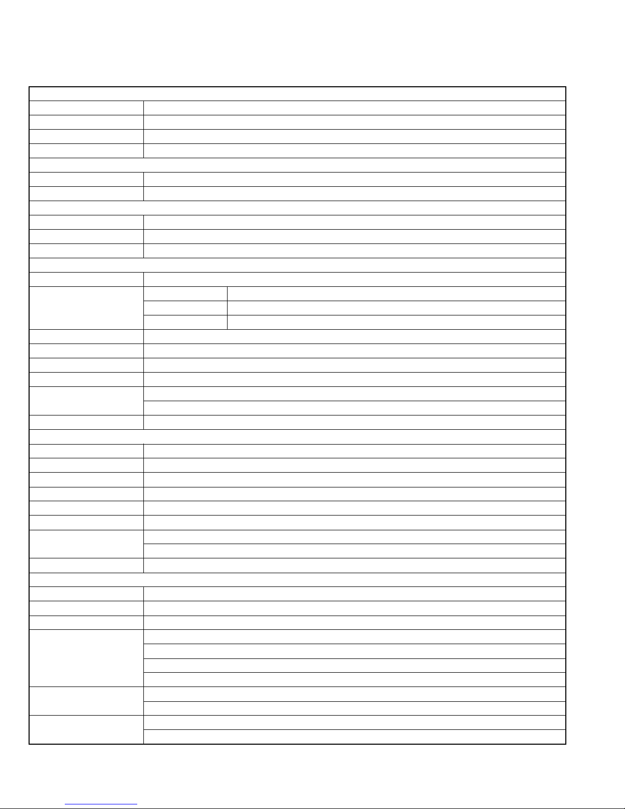
SPECIFICATION
MX-KC68J/C/MX-KC38J/C
Amplifier section OUTPUT POWER
Main speakers 110 W per channel min. RMS driven into 3Ω at 1 kHz with no more than 10% total harmonic distortion
Speakers/Impedance 3Ω - 6 Ω
Subwoofer (for MX-KC68) 180 W per channel min. RMS driven into 8 Ω at 63 Hz with no more than 10% total harmonic distortion
Speakers/Impedance 8 Ω - 16 Ω
Tuner section
FM tuning range 87.5 MHz - 108.0 MHz
AM tuning range 530 kHz - 1 710 kHz
CD player section
Dynamic range 90 dB
Signal-to-noise ratio 85 dB
Wow and flutter Immeasurable
Main speakers (MX-KC68/SP-MXKC38)
Type 3-Way 3-Speaker Bass-Reflex Type
Speaker units Main Woofer 16 cm (6-5/16 inches) cone x 1
Mid Range 5 cm (2 inches) cone x 1
Tweeter 2 cm (13/16 inches) dome x 1
Power Handling Capacity 110 W
Impedance 3 Ω
Frequency Range 41 Hz - 35 kHz
Sound Pressure Level 83 dB/W•m
Dimensions (approx.) 210 mm x 315 mm x 220 mm (W/H/D)
(8-5/16 inches x 12-7/16 inches x 8-11/16 inches)
Mass (approx.) 3.0 kg (6.7 lbs) each
Subwoofer (MX-KC68)
Type 1-Way Bass-Reflex Type
Speaker 16 cm (6-5/16 inches) cone x 1
Power Handling Capacity 180 W
Impedance 8 Ω
Frequency Range 38 Hz - 5 kHz
Sound Pressure Level 83 dB/W•m
Dimensions (approx.) 210 mm x 315 mm x 242 mm (W/H/D)
(8-5/16 inches x 12-7/16 inches x 9-9/16 inches)
Mass (approx.) 3.4 kg (7.5 lbs)
General
Power requirements AC 120 V , 60 Hz
Audio input AUDIO IN 400 mV/47 kΩ
Power supply to iPod DC 5 V 500 mA
Power consumption 95 W (MX-KC68) - power on
60 W (MX-KC38) - power on
9 W - standby mode, without charging iPod
0.9 W or less - save mode
Dimensions (W x H x D) 215 mm x 307 mm x 309 mm
(8-1/2 inches x 12-1/8 inches x 12-3/16 inches)
Mass (approx.) 3.8 kg (8.4 lbs) (MX-KC68)
3.6 kg (8.0 lbs) (MX-KC38)
Specifications and appearance are subject to change without prior notice.
1-2 (No.MB664<Rev.002>)
Page 3
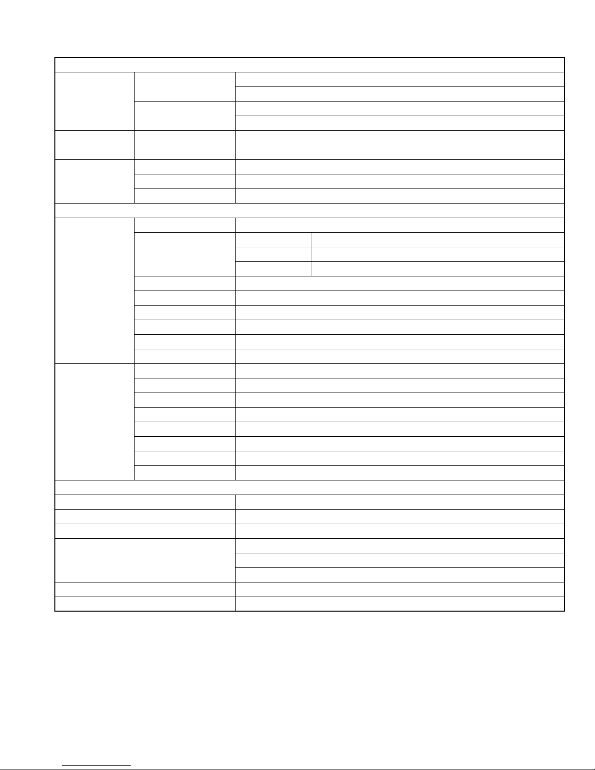
MX-KC68B/E/EN/EV
Amplifier section
OUTPUT POWER Main speakers
Subwoofer
Tuner section FM tuning range 87.50 MHz - 108.00 MHz
AM tuning range 522 kHz - 1 629 kHz
CD player section Dynamic range 86 dB
Signal-to-noise ratio 85 dB
Wow and flutter Immeasurable
Main speakers
(SP-MXKC68F)
Subwoofer
(SP-MXKC68W)
Power requirements AC 230 V , 50 Hz
Audio input AUDIO IN 400 mV/47 kΩ
Power supply to iPod DC 5 V 500 mA
Power consumption 95 W - power on
Dimensions (W x H x D) 215 mm x 307 mm x 309 mm
Mass (approx.) 3.8 kg
Specifications and appearance are subject to change without prior notice.
Type 3-Way 3-Speaker Bass-Reflex Type
Speaker units Main Woofer 16 cm cone x 1
Power Handling Capacity 110 W
Impedance 3 Ω
Frequency Range 41 Hz - 35 kHz
Sound Pressure Level 83 dB/W
Dimensions (approx.) 210 mm x 315 mm x 220 mm (W/H/D)
Mass (approx.) 3.0 kg each
Type 1-Way Bass-Reflex Type
Speaker 16 cm cone x 1
Power Handling Capacity 180 W
Impedance 8 Ω
Frequency Range 38 Hz - 5 kHz
Sound Pressure Level 83 dB/W
Dimensions (approx.) 210 mm x 315 mm x 242 mm (W/H/D)
Mass (approx.) 3.4 kg
110 W per channel min. RMS driven into 3 Ω at 1 kHz with no more than 10% total harmonic distortion
Speakers/Impedance: 3 Ω - 6 Ω
180 W min. RMS driven into 8 Ω at 63 Hz with no more than 10% total harmonic distortion
Speakers/Impedance: 8 Ω - 16 Ω
Speakers
Mid Range 5 cm cone x 1
Tweeter 2 cm dome x 1
•m
•m
General
9 W - standby mode, without charging iPod
0.8 W or less - save mode
(No.MB664<Rev.002>)1-3
Page 4
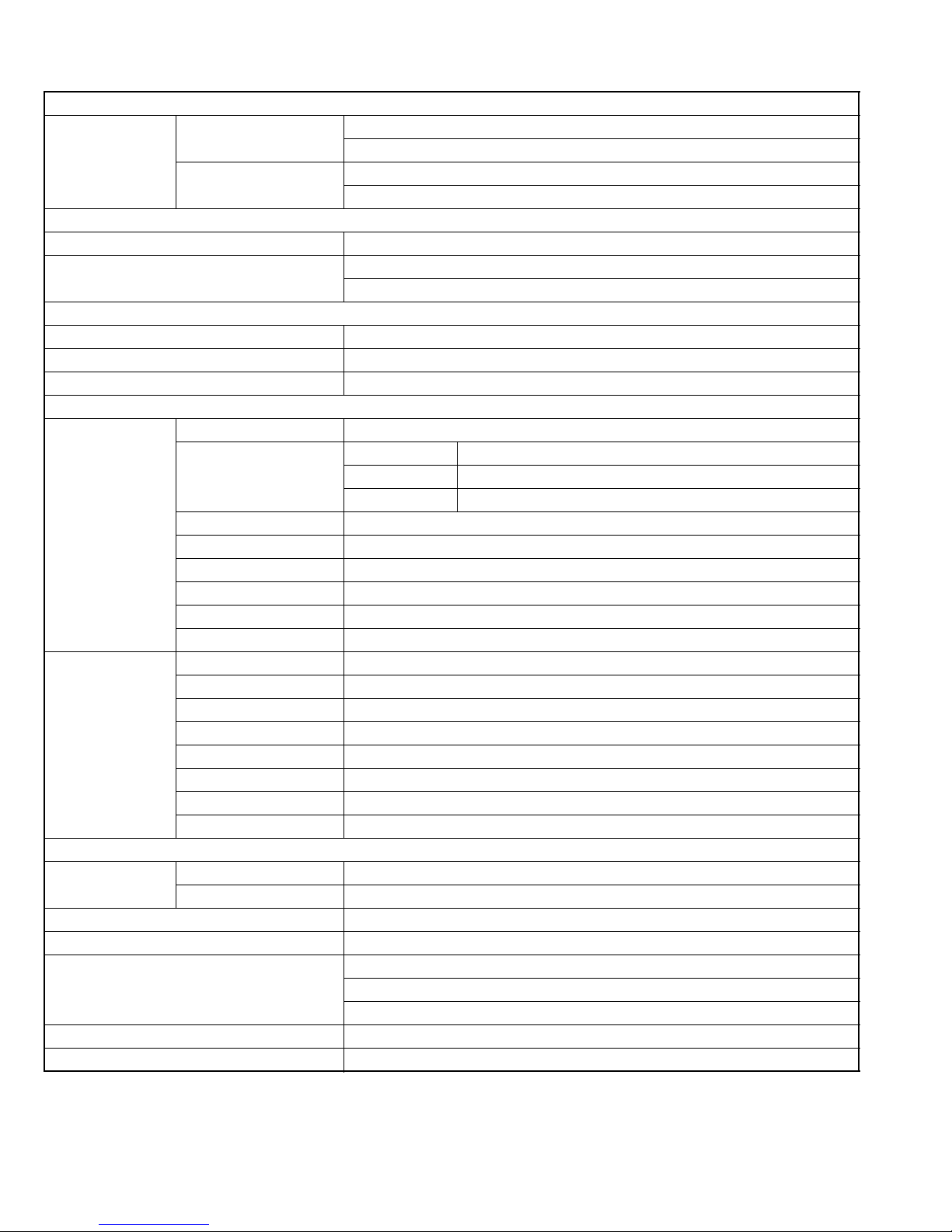
MX-KC68A/UJ/UW
Amplifier section
OUTPUT POWER Main speakers
Subwoofer
FM tuning range 87.50 MHz - 108.00 MHz
AM tuning range 531 kHz - 1 710 kHz (at 9 kHz intervals)
Dynamic range 86 dB
Signal-to-noise ratio 85 dB
Wow and flutter Immeasurable
Main speakers (SPMXKC68F)
Subwoofer
(SP-MXKC68W)
Power requirements For Australia AC 240 V , 50 Hz
Audio input AUDIO IN 400 mV/47 kΩ
Power supply to iPod DC 5 V 500 mA
Power consumption 95 W - power on
Dimensions (W x H x D) 215 mm x 307 mm x 309 mm
Mass (approx.) 3.8 kg
Specifications and appearance are subject to change without prior notice.
Type 3-Way 3-Speaker Bass-Reflex Type
Speaker units Main Woofer 16 cm cone x 1
Power Handling Capacity 110 W
Impedance 3 Ω
Frequency Range 41 Hz - 35 kHz
Sound Pressure Level 83 dB/W
Dimensions (approx.) 210 mm x 315 mm x 220 mm (W/H/D)
Mass (approx.) 3.0 kg each
Type 1-Way Bass-Reflex Type
Speaker 16 cm cone x 1
Power Handling Capacity 180 W
Impedance 8 Ω
Frequency Range 38 Hz - 5 kHz
Sound Pressure Level 83 dB/W
Dimensions (approx.) 210 mm x 315 mm x 242 mm (W/H/D)
Mass (approx.) 3.4 kg
For other countries AC 110 V-127 V/AC 220 V-240 V adjustable with the voltage selector 50 Hz/60 Hz
110 W per channel min. RMS driven into 3 Ω at 1 kHz with no more than 10% total harmonic distortion
Speakers/Impedance: 3 Ω - 6 Ω
180 W per channel min. RMS driven into 8 Ω at 63 Hz with no more than 10% total harmonic distortion
Speakers/Impedance: 8 Ω - 16 Ω
Tuner section
530 kHz - 1 710 kHz (at 10 kHz intervals)
CD player section
Speakers
Mid Range 5 cm cone x 1
Tweeter 2 cm dome x 1
•m
•m
General
9 W - standby mode, without charging iPod
0.8 W or less - save mode
1-4 (No.MB664<Rev.002>)
Page 5
SECTION 1
PRECAUTION
1.1 Safety Precautions
(1) This design of this product contains special hardware and
many circuits and components specially for safety purposes. For continued protection, no changes should be made
to the original design unless authorized in writing by the
manufacturer. Replacement parts must be identical to
those used in the original circuits. Services should be performed by qualified personnel only.
(2) Alterations of the design or circuitry of the product should
not be made. Any design alterations of the product should
not be made. Any design alterations or additions will void
the manufacturers warranty and will further relieve the
manufacture of responsibility for personal injury or property
damage resulting therefrom.
(3) Many electrical and mechanical parts in the products have
special safety-related characteristics. These characteristics are often not evident from visual inspection nor can the
protection afforded by them necessarily be obtained by using replacement components rated for higher voltage, wattage, etc. Replacement parts which have these special
safety characteristics are identified in the Parts List of Service Manual. Electrical components having such features
are identified by shading on the schematics and by ( ) on
the Parts List in the Service Manual. The use of a substitute
replacement which does not have the same safety characteristics as the recommended replacement parts shown in
the Parts List of Service Manual may create shock, fire, or
other hazards.
(4) The leads in the products are routed and dressed with ties,
clamps, tubings, barriers and the like to be separated from
live parts, high temperature parts, moving parts and/or
sharp edges for the prevention of electric shock and fire
hazard. When service is required, the original lead routing
and dress should be observed, and it should be confirmed
that they have been returned to normal, after reassembling.
(5) Leakage shock hazard testing
After reassembling the product, always perform an isolation check on the exposed metal parts of the product (antenna terminals, knobs, metal cabinet, screw heads,
headphone jack, control shafts, etc.) to be sure the product
is safe to operate without danger of electrical shock.Do not
use a line isolation transformer during this check.
• Plug the AC line cord directly into the AC outlet. Using a
"Leakage Current Tester", measure the leakage current
from each exposed metal parts of the cabinet, particularly any exposed metal part having a return path to the
chassis, to a known good earth ground. Any leakage current must not exceed 0.5mA AC (r.m.s.).
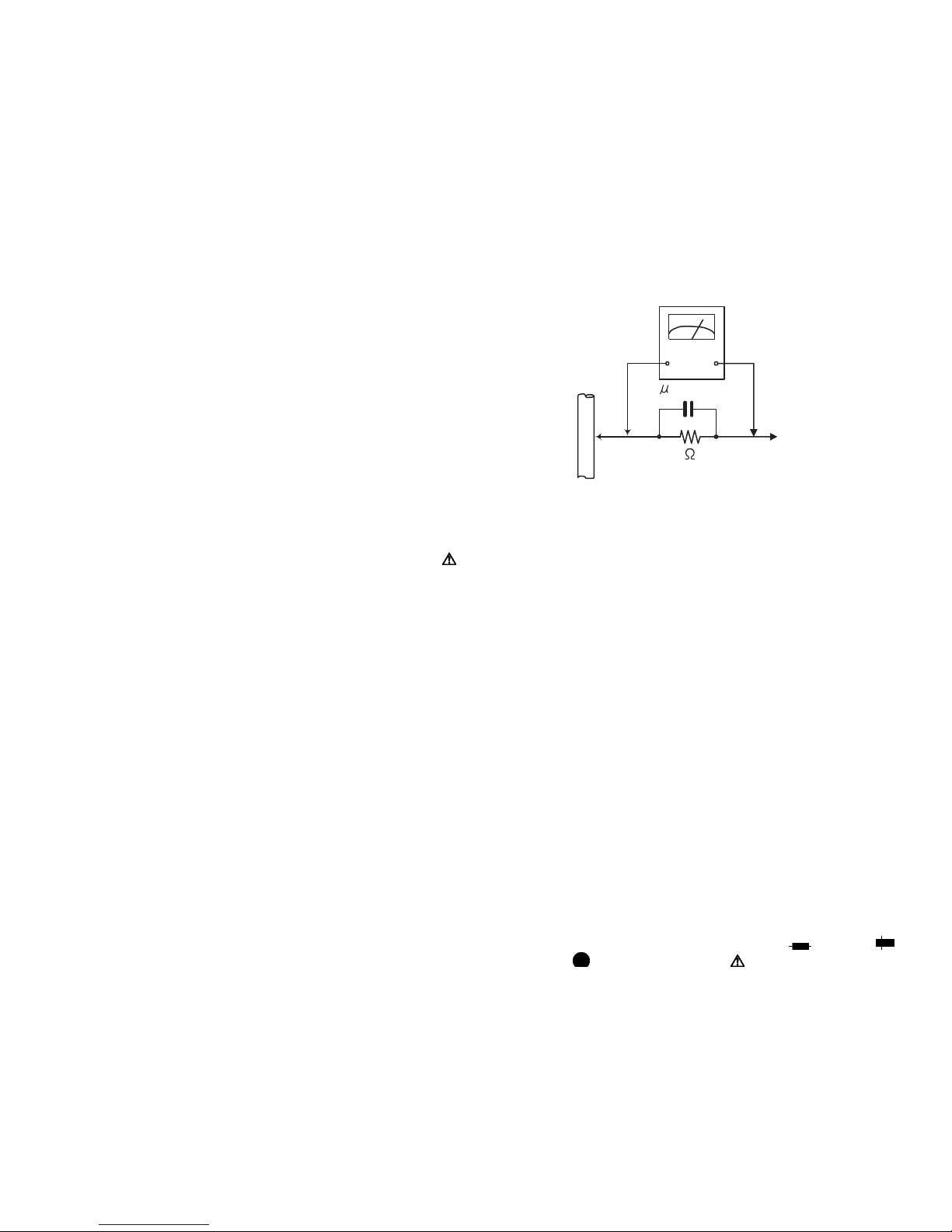
• Alternate check method
Plug the AC line cord directly into the AC outlet. Use an
AC voltmeter having, 1,000Ω per volt or more sensitivity
in the following manner. Connect a 1,500Ω 10W resistor
paralleled by a 0.15µF AC-type capacitor between an ex-
posed metal part and a known good earth ground.
Measure the AC voltage across the resistor with the AC
voltmeter.
Move the resistor connection to each exposed metal
part, particularly any exposed metal part having a return
path to the chassis, and measure the AC voltage across
the resistor. Now, reverse the plug in the AC outlet and
repeat each measurement. Voltage measured any must
not exceed 0.75 V AC (r.m.s.). This corresponds to 0.5
mA AC (r.m.s.).
AC VOLTMETER
(Having 1000
ohms/volts,
or more sensitivity)
0.15 F AC TYPE
Place this
probe on
1500 10W
Good earth ground
1.2 Warning
(1) This equipment has been designed and manufactured to
meet international safety standards.
(2) It is the legal responsibility of the repairer to ensure that
these safety standards are maintained.
(3) Repairs must be made in accordance with the relevant
safety standards.
(4) It is essential that safety critical components are replaced
by approved parts.
(5) If mains voltage selector is provided, check setting for local
voltage.
1.3 Caution
Burrs formed during molding may be left over on some parts
of the chassis.
Therefore, pay attention to such burrs in the case of preforming repair of this system.
1.4 Critical parts for safety
In regard with component parts appearing on the silk-screen
printed side (parts side) of the PWB diagrams, the parts that are
printed over with black such as the resistor ( ), diode ( )
and ICP ( ) or identified by the " " mark nearby are critical
for safety. When replacing them, be sure to use the parts of the
same type and rating as specified by the manufacturer.
(This regulation dose not Except the J and C version)
each exposed
metal part.
(No.MB664<Rev.002>)1-5
Page 6
1.5 Preventing static electricity
Electrostatic discharge (ESD), which occurs when static electricity stored in the body, fabric, etc. is discharged, can destroy the laser
diode in the traverse unit (optical pickup). Take care to prevent this when performing repairs.
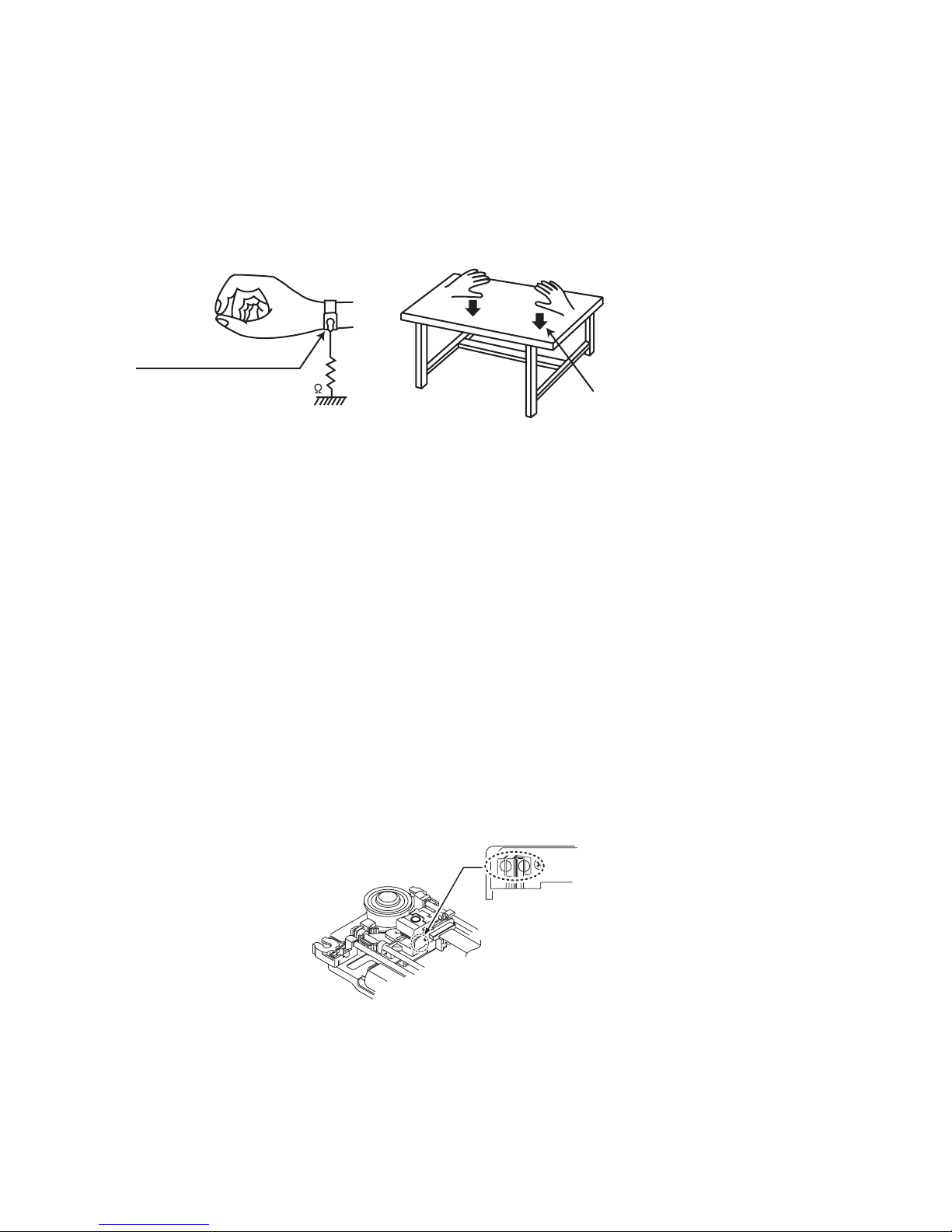
1.5.1 Grounding to prevent damage by static electricity
Static electricity in the work area can destroy the optical pickup (laser diode) in devices such as laser products.
Be careful to use proper grounding in the area where repairs are being performed.
(1) Ground the workbench
Ground the workbench by laying conductive material (such as a conductive sheet) or an iron plate over it before placing the
traverse unit (optical pickup) on it.
(2) Ground yourself
Use an anti-static wrist strap to release any static electricity built up in your body.
(caption)
Anti-static wrist strap
1M
Conductive material
(conductive sheet) or iron palate
(3) Handling the optical pickup
• In order to maintain quality during transport and before installation, both sides of the laser diode on the replacement optical
pickup are shorted. After replacement, return the shorted parts to their original condition.
(Refer to the text.)
• Do not use a tester to check the condition of the laser diode in the optical pickup. The tester's internal power source can easily
destroy the laser diode.
1.6 Handling the traverse unit (optical pickup)
(1) Do not subject the traverse unit (optical pickup) to strong shocks, as it is a sensitive, complex unit.
(2) Cut off the shorted part of the flexible cable using nippers, etc. after replacing the optical pickup. For specific details, refer to the
replacement procedure in the text. Remove the anti-static pin when replacing the traverse unit. Be careful not to take too long a
time when attaching it to the connector.
(3) Handle the flexible cable carefully as it may break when subjected to strong force.
(4) I t is not possible to adjust the semi-fixed resistor that adjusts the laser power. Do not turn it.
1.7 Attention when traverse unit is decomposed
*Please refer to "Disassembly method" in the text for the pickup unit.
• Apply solder to the short land sections before the card wire is disconnected from the connecto on the servo board. (If the card wire
is disconnected without applying solder, the pickup may be destroyed by static electricity.)
• In the assembly, be sure to remove solder from the short land sections after connecting the card wire.
Solder short land section
1-6 (No.MB664<Rev.002>)
Page 7

1.8 Important for laser products
1.CLASS 1 LASER PRODUCT
2.CAUTION :
(For U.S.A.) Visible and/or invisible class II laser radiation
when open. Do not stare into beam.
(Others) Visible and/or invisible class 1M laser radiation
when open. Do not view directly with optical instruments.
3.CAUTION : Visible and/or invisible laser radiation when
open and inter lock failed or defeated. Avoid direct
exposure to beam.
4.CAUTION : This laser product uses visible and/or invisible
laser radiation and is equipped with safety switches which
prevent emission of radiation when the drawer is open and
the safety interlocks have failed or are defeated. It is
dangerous to defeat the safety switches.
5.CAUTION : If safety switches malfunction, the laser is able
to function.
6.CAUTION : Use of controls, adjustments or performance of
procedures other than those specified here in may result in
hazardous radiation exposure.
!
Please use enough caution not to
see the beam directly or touch it
in case of an adjustment or operation
check.
REPRODUCTION AND POSITION OF LABELS and PRINT
WARNING LABEL and PRINT
(No.MB664<Rev.002>)1-7
Page 8

SECTION 2
A
SPECIFIC SERVICE INSTRUCTIONS
New CD mechanism was added.
In a model using new CD mechanism for, it stick a blue label for identification on the back side.
When it repair the CD mechanism of an article sticking this label on, please use a parts list of FMU-VK1-2M.
A label for identification
SECTION 3
DISASSEMBLY
3.1 Main body (Used figure are MX-KC68J)
3.1.1 Removing the Metal cover (See Fig.1, 2)
(1) Remove the six screws A attaching the Metal cover. (See
Fig.1)
(2) Remove the four screws B attaching the both side of the
Metal cover. (See Fig.2)
A
B
Fig.2
1-8 (No.MB664<Rev.002>)
Fig.1
Page 9

3.1.2 Removing the Tuner pack (See Fig.3, 4)
(1) Disconnect the card wire from Tuner pack connected to
connector CN707
(2) Remove the two screws C attaching the Tuner pack. (See
Fig.4)
of the Micom board. (See Fig.3)
CN707
Fig.3
C
3.1.3 Removing the CD mechanism (See Fig.5, 6)
(1) Disconnect the card wire from CD mechanism connected
to connector CN708
(2) Disconnect the card wire from Loader board connected to
connector CN709 of the Micom board. (See fig.5)
(3) Remove the three screws D attaching the CD mechanism.
(See Fig.6)
of the Micom board. (See Fig.5)
Fig.4
DD
D
Fig.6
CN708 CN709
Fig.5
(No.MB664<Rev.002>)1-9
Page 10

3.1.4 Removing the CD chassis (See Fig.7, 8)
(1) Remove the two screws E attaching the both side of the
Front panel. (See Fig.7)
(2) Remove the two screws F attaching the CD chassis. (See
Fig.8)
E
Fig.7
F
Fig.8
3.1.5 Removing the Front panel (See Fig.9 to 11)
(1) Disconnect he card wire from FL board connected to con-
nector CN700
(2) Disconnect the card wire from Volume board connected to
connector CN701 of the Micom board. (See Fig.9)
(3) Disconnect the connector wire from iPod jack board con-
nected to connector CN702
Fig.9)
(4) Disconnect the flat cable wire from Audio input board con-
nected to connector CN705
Fig.9)
(5) Remove the three screws G attaching the Front panel.
(See Fig.10)
(6) Disengage two hooks a engaged both side of the Front
panel. (See Fig.11)
CN700
CN701
CN702
of the Micom board. (See Fig.9)
of the Micom board. (See
of the Micom board. (See
G
Fig.10
CN705
Fig.9
1-10 (No.MB664<Rev.002>)
Fig.11
hook
a
Page 11

3.1.6 Removing the Rear panel (See Fig.12, 13)
(1) Disconnect the connector wire from Fan connected to con-
nector CN706
(2) Remove the four screws H attaching the Rear panel. (See
Fig.13)
of the Micom board. (See Fig.12)
CN706
Fig.12
H
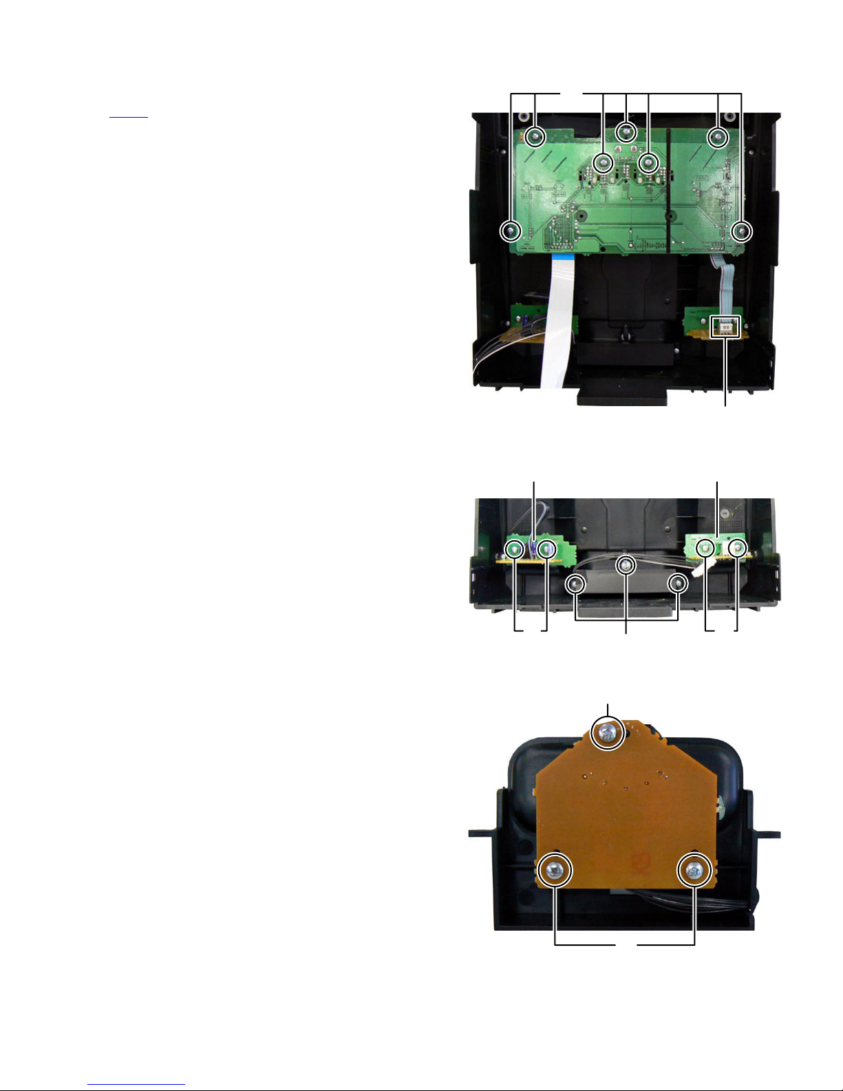
3.1.7 Removing the Micom board (See Fig.14, 15)
(1) Remove the one screw J attaching the Micom board. (See
Fig.14)
(2) Disconnect the connector wire from Micom board connect-
ed to connector CN3
(3) Disconnect the board to board connectors connected to
connectors CN501 and CN502 of the Power amp board.
(See Fig.15)
of the Power supply unit. (See Fig.15)
J
Fig.14
H
Fig.13
CN3
CN501 CN502
Fig.15
(No.MB664<Rev.002>)1-11
Page 12

3.1.8 Removing the Power supply unit (See Fig.16)
(1) Disconnect the Power cord connected to connector CN1 of
the Power supply unit.
(2) Disconnect the connector wire from Power amp board con-
nected to connector CN2
(3) Remove the six screws K attaching the Power supply unit.
3.1.9 Removing the Power amp board (See Fig.16)
(1) Remove the four screws L attaching the Power amp board.
of the Power supply unit.
CN2
K
L
3.1.10 Removing the FL board (See Fig.17)
(1) Remove the four screws M attaching the FL board.
Fig.16
M
M
Fig.17
KL
CN1
1-12 (No.MB664<Rev.002>)
Page 13
3.1.11 Removing the Volume board (See Fig.18)
(1) Remove the volume knob.
(2) Disconnect the flat cable wire connected to connector
of the Headphone jack board.
CN951
(3) Remove the seven screws N attaching the Volume board.
3.1.12 Removing the Audio input board (See Fig.19)
(1) Remove the two screws P attaching the Audio input board.
3.1.13 Removing the Headphone jack board (See Fig.19)
(1) Remove the two screws Q attaching the Headphone jack
board.
N
CN951
Fig.18
Audio input board Headphone jack board
3.1.14 Removing the iPod jack board (See Fig.19, 20)
(1) Remove the three screws R attaching the iPod holder.
(See Fig.20)
(2) Remove the three screws S attaching the iPod jack board.
(See Fig.20)
PQ
R
Fig.19
S
S
Fig.20
(No.MB664<Rev.002>)1-13
Page 14
3.2 CD mechanism assembly
• Remove the CD mechanism assembly from main body.
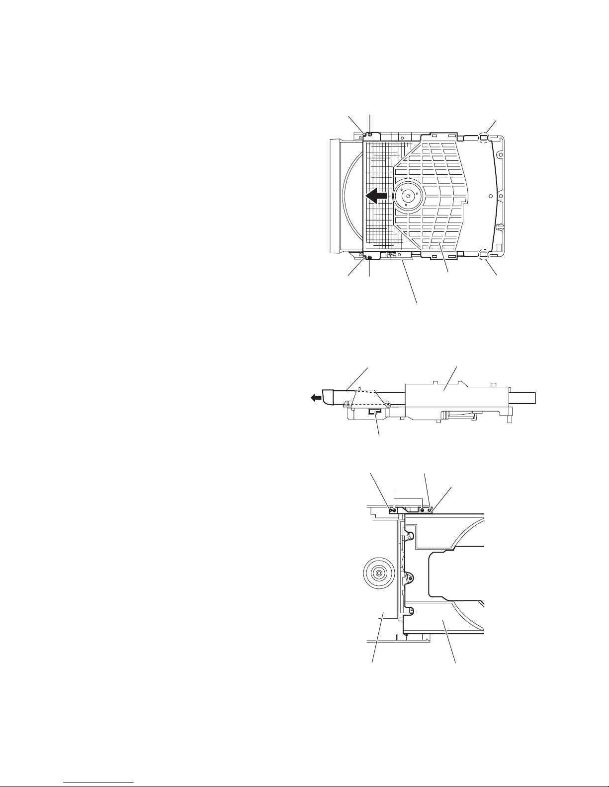
3.2.1 Removing the CD cover
(See Fig.1)
(1) Remove the two screws A attaching the CD cover from bot-
tom side of CD mechanism assembly.
(2) Lift up the CD cover from disengage boss a of the CD
mechanism assembly.
(3) Slide the CD cover to direction of the arrow and remove the
CD cover from fixing part of b.
(4) Remove the CD cover.
Boss a
A
Fixing part b
3.2.2 Removing the tray assembly
(See Fig.2 and 3)
• Remove the CD cover.
(1) Press slide cam and pull out the tray assembly to direction
of the arrow from right side of CD mechanism assembly.
(See Fig.2)
(2) Remove the two screws B attaching the tray assembly
from upper side of CD mechanism. (See Fig.3)
(3) Remove the bussing of the tray assembly from boss c of
the CD mechanism assembly and remove the tray assembly. (See Fig.3)
Boss a
A
CD mechanism assembly
Tray assembly CD mechanism assembly
Slide cam
Boss c
B
CD cover
Fig.1
Fig.2
Boss c
Bussing
Fixing part b
1-14 (No.MB664<Rev.002>)
Tray assemblyCD mechanism assembly
Fig.3
Page 15

3.2.3 Removing the traverse mechanism assembly
(See Fig.4)
(1) Remove the four screws C attaching the traverse mecha-
nism assembly from bottom side of CD mechanism assembly.
(2) Disconnect the card wire from connector CN602
servo board and then take out the traverse mechanism assembly and CD servo board together.
Reference:
When reattaching the traverse mechanism assembly, the card
wire should through the part d.
of the CD
Card wire
d
CD mechanism assembly
CD servo board
C
Traverse mechanism assembly
Fig.4
C
CN602
(No.MB664<Rev.002>)1-15
Page 16

3.2.4 Removing the CD servo board
(See Fig.5 and 6)
• Remove the traverse mechanism assembly.
(1) Remove the two screws D attaching the CD servo board
from bottom side of traverse mechanism assembly. (See
Fig.5)
(2) Remove the solder from solder part e of the CD servo
board. (See Fig.5)
(3) Remove the yellow wire from solder part f of the CD servo
board. (See Fig.5)
(4) Remove the white wire from solder part g of the CD servo
board. (See Fig.5)
(5) Remove the CD servo board to upper side, disengage the
hook c to direction of the arrow 1 then turn over the CD ser-
vo board. (See Fig.5)
(6) Solder to short land part j of pickup. (See Fig.6)
(7) Release the lock of connector CN601
row 2 and disengage the card wire. (See Fig.6)
Caution:
• Solder to short land part j of the pickup then disconnect the
card wire from connector CN601
disconnect the card wire before soldering, pickup is make
sure destroyed by static electricity. (See Fig.6)
• When reattaching the CD servo board, connect the card wire
to connector CN601 and then remove the solder of short
land part j of the pickup.
to direction of the ar-
of the CD servo board. If
CN601
Hook c
Solder part e
1
CD servo board
Traverse mechanism assemblyCD servo board
Fig.5
DD
Yellow wire
White wire
1
Hook c
Solder
part f
Solder
part g
Pickup
Short land part j
CN601
22
Traverse mechanism assembly
Fig.6
1-16 (No.MB664<Rev.002>)
Page 17

3.2.5 Removing the pickup
(See Fig.7 to 9)
• Remove the traverse mechanism assembly.
(1) Remove the one screw E attaching the plate from upper
side of traverse mechanism assembly. (See Fig.7)
(2) Remove the plate from fixing part k then take out the plate.
(See Fig.7)
(3) Remove the two screws F attaching the LEAD spring and
then take out the LEAD spring. (See Fig.8)
(4) Take out the feed gear, and then remove the shaft of pick-
up from part m of the traverse mechanism assembly. (See
Fig.8)
(5) Remove the pickup from part n of the traverse mechanism
assembly and then take out pickup with shaft. (See Fig.8)
(6) Release the shaft from pickup. (See Fig.8)
(7) Solder the short land part p of the pickup. (See Fig.9)
(8) Release the lock of the connector to direction of the arrow,
and then disconnect the card wire. (See Fig9)
Caution:
• Solder to short land part p of the pickup then disconnect the
card wire from connector. If disconnect the card wire before
soldering, pickup is make sure destroyed by static electricity.
(See Fig.9)
• When reattaching the pickup, connect the card wire to con-
nector and then remove the solder from short land part p.
(See Fig.9)
Feed gear Shaft LEAD spring
Pickup
Short land part
p
F
Part n
Fig.8
Part m
3.2.6 Attaching the pickup
(See Fig.7 to 10)
• Please refer the "Removing the pickup".
(1) Connect the card wire to connector of pickup, and then re-
move the solder from short land part p of the pickup. (See
Fig.9)
(2) Attach the shaft to pickup. (See Fig.8)
(3) Fit the pickup to part n of the traverse mechanism and then
attach the end of the shaft to part k. (See Fig.8)
(4) Attach the LEAD spring and feed gear. (See Fig.8)
(5) Attach the plate. (See Fig. 7)
(6) One turn the LEAD gear to direction of the arrow 1 and fully
shift to direction of the arrow 2. (See Fig.10)
Plate
Fixing part k
E
Pickup Connector Card wire
Fig.9
LEAD gear
1
2
Traverse mechanism assembly
Fig.10
Pickup
Traverse mechanism assembly
Fig.7
(No.MB664<Rev.002>)1-17
Page 18

3.2.7 Removing the feed motor
(See Fig.11 to 13)
• Remove the traverse mechanism.
(1) Remove the yellow wire from solder part q of the CD servo
board from upper side of traverse mechanism. (See Fig.11)
(2) Remove the white wire from solder part r of the CD servo
board. (See Fig.11)
(3) Remove the one screw G attaching the plate. (See Fig.12)
(4) Disengage the plate from fixing part s and take out the
plate. (See Fig.12)
(5) Remove the feed gear and take out the feed motor. (See
Fig13)
Reference:
When attaching the feed motor, the wire has to through the
part t of the traverse mechanism assembly. (See Fig.13)
Yellow wire
White wire
Soldered part q
Soldered part r
Feed gear Feed motor
Traverse mechanism assembly
Fig.13
part
t
Fixing part s
Traverse mechanism assembly
G
Traverse mechanism assemblyCD servo board
Fig.11
Plate
Fig.12
1-18 (No.MB664<Rev.002>)
Page 19

3.2.8 Removing the switch board
(See Fig.14)
(1) Disconnect the card wire from CN1
from bottom side of CD mechanism assembly.
(2) Remove the wire from solder part u of the switch board.
(3) Remove the one screw H attaching the switch board to CD
mechanism assembly.
(4) Lift up the switch board by pushing the hook v of CD mech-
anism assembly and take out it from part w.
Reference:
• After attach the switch board to CD mechanism assembly,
wire hooked to part x.
•Hook u of the CD mechanism assembly, it have to bond
lock.
3.2.9 Removing the motor
(See Fig.14 and 15)
• Remove the tray assembly.
(1) Remove the wire from solder part u of the switch board
from bottom side of CD mechanism assembly.
(2) Remove the belt of motor pulley from upper side of CD
mechanism assembly. (See Fig.15)
Caution:
Belt should not apply grease.
(3) Remove the two screws J attaching the motor to CD mech-
anism assembly and take out the motor from bottom side
of CD mechanism assembly. (See Fig.15)
Reference:
After motor attached to CD mechanism assembly, wire should
hook to part w. (See Fog.14)
of the switch board
Switch board Wire
Solder
part u
CN1
Part w
H
CD mechanism assembly
J
Hook v
Part x
CD mechanism assembly
Fig.14
Belt
Fig.15
Motor pulley
(No.MB664<Rev.002>)1-19
Page 20

4.1 Outline
4.2 How to go CD TEST MODE
[SET] + [POWER] + AC in
4.3 Function specification
SECTION 4
ADJUSTMENT
CD TEST MODE
C1 error display
Function
CD TEST MODE
C1 error display
C1 error display
Return to CD TEST MODE
4.4 C1 error history
When 8 key is pressed, syscon send C1 err display command (0x9C 0x01 0x00).
If syscon receive C1 error display status (0xAA 0x01 0x00 ** **), it displays C1 error.
Syscon convert 2byte hex data to decimal data (00000-65635).
4.5 Special mode
[STOP] + [POWER] + [ 0 ] : COLD SET
[STOP] + [POWER] + [ 1 ] : FL DISPLAY turn on all segment
[STOP] + [POWER] + [10] :Micom version display (Mecha version, Destination, Syscon version)
Exsample In case of " 2501 JC241"
Mecha version: 25
ROM corr: 1
Destination: JC
Syscon version: 24
Syscon corr: 1
Key Operation FL display
CD TESTT
8
CANCEL
Remocon
Remocon After receive data
Remocon
INITIAL
Er
CD TESTT
*****
1-20 (No.MB664<Rev.002>)
Page 21

SECTION 5
TROUBLESHOOTING
This service manual does not describe TROUBLESHOOTING.
(No.MB664<Rev.002>)1-21
Page 22

Victor Company of Japan, Limited
Audio/Video Systems category 10-1,1chome,Ohwatari-machi,Maebashi-city,371-8543,Japan
(No.MB664<Rev.002>)
Printed in Japan
VPT
 Loading...