

Page 1
SERVICE MANUAL
COMPACT COMPONENT SYSTEM
MB51020063
MX-KC45J,MX-KC45C
CA-MXKC45SP-MXKC45 SP-MXKC45
Lead free solder used in the board (material : Sn-Ag-Cu, melting point : 219 Centigrade)
TABLE OF CONTENTS
1 PRECAUTION. . . . . . . . . . . . . . . . . . . . . . . . . . . . . . . . . . . . . . . . . . . . . . . . . . . . . . . . . . . . . . . . . . . . . . . . . 1-3
2 SPECIFIC SERVICE INSTRUCTIONS . . . . . . . . . . . . . . . . . . . . . . . . . . . . . . . . . . . . . . . . . . . . . . . . . . . . . . 1-4
3 DISASSEMBLY . . . . . . . . . . . . . . . . . . . . . . . . . . . . . . . . . . . . . . . . . . . . . . . . . . . . . . . . . . . . . . . . . . . . . . . 1-5
4 ADJUSTMENT . . . . . . . . . . . . . . . . . . . . . . . . . . . . . . . . . . . . . . . . . . . . . . . . . . . . . . . . . . . . . . . . . . . . . . . . 1-9
5 TROUBLESHOOTING . . . . . . . . . . . . . . . . . . . . . . . . . . . . . . . . . . . . . . . . . . . . . . . . . . . . . . . . . . . . . . . . . . 1-9
COPYRIGHT © 2006 Victor Company of Japan, Limited
No.MB510
2006/3
Page 2
SPECIFICATION
Amplifier Output Power 200 W per channel, min. RMS, driven into 6 Ω at 1kHz, with no more than
10% total harmonic distortion
Input Sensitivity/Impedance
(1 kHz)
Cassette Deck Section Frequency Response Type I (NORMAL) : 63 Hz - 12 500 Hz
CD Player CD Capacity 3 CDs
Tuner (Tuning Range) FM Tuner 87.5 MHz - 108.0 MHz
Unit Dimensions (W/H/D) 270 mm × 307 mm × 492mm (10-11/16" × 12-1/8" × 19-3/8")
Speaker Specifications
SP-MXKC45 (each unit)
Power Specifications Power Requirements AC 120 V , 60 Hz
AUX IN 400 mV/50 kΩ
Speaker terminals 6 - 16 Ω
Phones 32 Ω - 1 kΩ
17 mW/ch output into 32 Ω
Wow And Flutter : 0.15% (WRMS)
Dynamic Range 85 dB
Signal-To-Noise Ratio 85 dB
Wow And Flutter Unmeasurable
AM Tuner 530 kHz - 1 710 kHz
Mass Approx. 9.3 kg (20.5 lbs)
Type 3-way bass-reflex type
Speaker Unit Woofer : 16 cm (6-5/16") cone × 1
Mid : 5cm (2") cone × 1
Tweeter : 2 cm (13/16") dome × 1
Power Handling Capacity 200 W
Impedance 6 Ω
Frequency Range 45 Hz - 22 000 Hz
Sound pressure level 87 dB/W·m
Dimensions (W/H/D) 220 mm × 324 mm × 238 mm (8-11/16" × 12-13/16" × 9-3/8")
Mass Approx. 3.6 kg (8 lbs)
Power Consumption 180 W (power on mode)
23 W (in Standby mode)
1 W (in ECO mode)
Design and specifications are subject to change without notice.
1-2 (No.MB510)
Page 3
SECTION 1
PRECAUTION
1.1 Safety Precautions
(1) This design of this product contains special hardware and
many circuits and components specially for safety purposes. For continued protection, no changes should be made
to the original design unless authorized in writing by the
manufacturer. Replacement parts must be identical to
those used in the original circuits. Services should be performed by qualified personnel only.
(2) Alterations of the design or circuitry of the product should
not be made. Any design alterations of the product should
not be made. Any design alterations or additions will void
the manufacturers warranty and will further relieve the
manufacture of responsibility for personal injury or property
damage resulting therefrom.
(3) Many electrical and mechanical parts in the products have
special safety-related characteristics. These characteristics are often not evident from visual inspection nor can the
protection afforded by them necessarily be obtained by using replacement components rated for higher voltage, wattage, etc. Replacement parts which have these special
safety characteristics are identified in the Parts List of Service Manual. Electrical components having such features
are identified by shading on the schematics and by ( ) on
the Parts List in the Service Manual. The use of a substitute
replacement which does not have the same safety characteristics as the recommended replacement parts shown in
the Parts List of Service Manual may create shock, fire, or
other hazards.
(4) The leads in the products are routed and dressed with ties,
clamps, tubings, barriers and the like to be separated from
live parts, high temperature parts, moving parts and/or
sharp edges for the prevention of electric shock and fire
hazard. When service is required, the original lead routing
and dress should be observed, and it should be confirmed
that they have been returned to normal, after reassembling.
(5) Leakage shock hazard testing
After reassembling the product, always perform an isolation check on the exposed metal parts of the product (antenna terminals, knobs, metal cabinet, screw heads,
headphone jack, control shafts, etc.) to be sure the product
is safe to operate without danger of electrical shock.Do not
use a line isolation transformer during this check.
• Plug the AC line cord directly into the AC outlet. Using a
"Leakage Current Tester", measure the leakage current
from each exposed metal parts of the cabinet, particularly any exposed metal part having a return path to the
chassis, to a known good earth ground. Any leakage current must not exceed 0.5mA AC (r.m.s.).
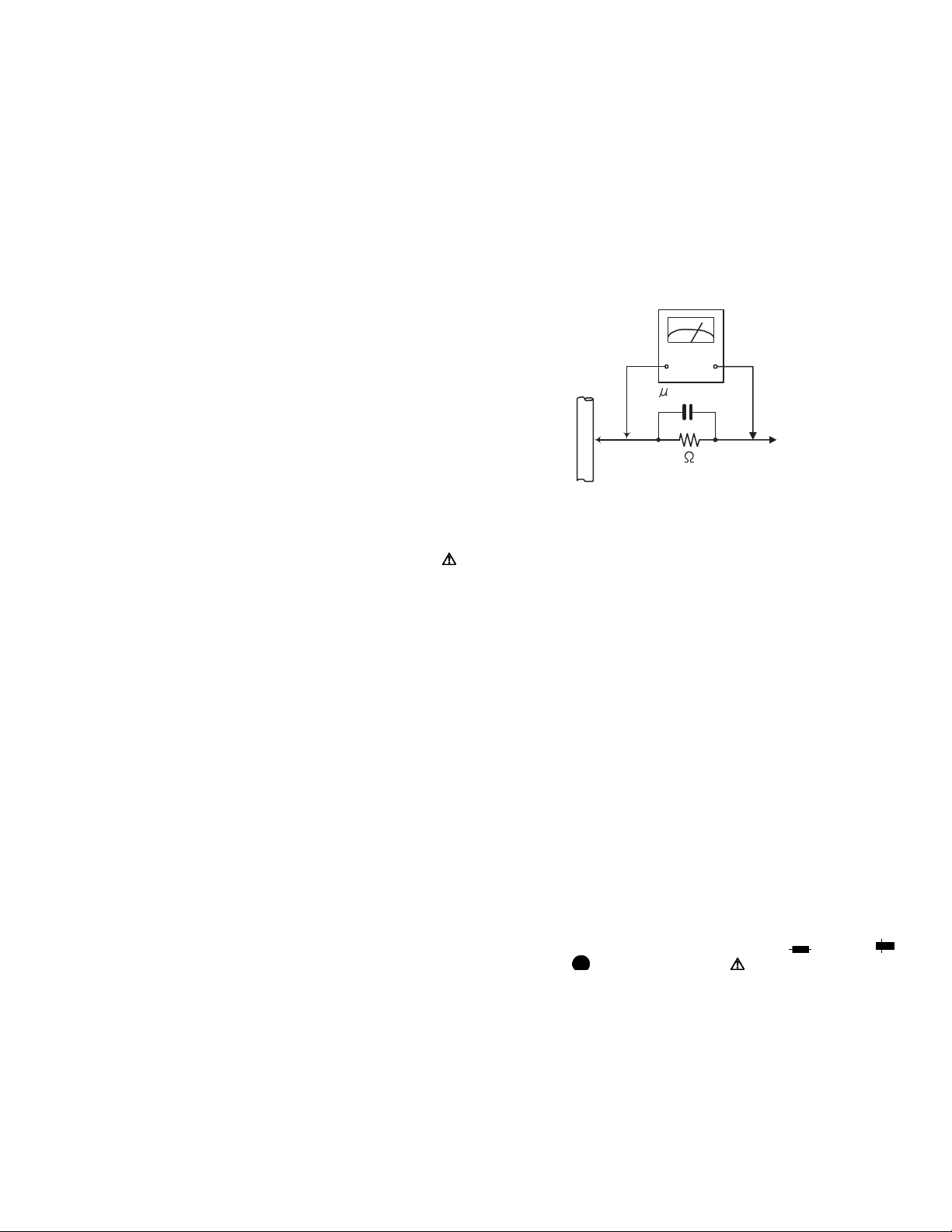
• Alternate check method
Plug the AC line cord directly into the AC outlet. Use an
AC voltmeter having, 1,000Ω per volt or more sensitivity
in the following manner. Connect a 1,500Ω 10W resistor
paralleled by a 0.15µF AC-type capacitor between an ex-
posed metal part and a known good earth ground.
Measure the AC voltage across the resistor with the AC
voltmeter.
Move the resistor connection to each exposed metal
part, particularly any exposed metal part having a return
path to the chassis, and measure the AC voltage across
the resistor. Now, reverse the plug in the AC outlet and
repeat each measurement. Voltage measured any must
not exceed 0.75 V AC (r.m.s.). This corresponds to 0.5
mA AC (r.m.s.).
AC VOLTMETER
(Having 1000
ohms/volts,
or more sensitivity)
0.15 F AC TYPE
Place this
probe on
1500 10W
Good earth ground
1.2 Warning
(1) This equipment has been designed and manufactured to
meet international safety standards.
(2) It is the legal responsibility of the repairer to ensure that
these safety standards are maintained.
(3) Repairs must be made in accordance with the relevant
safety standards.
(4) It is essential that safety critical components are replaced
by approved parts.
(5) If mains voltage selector is provided, check setting for local
voltage.
1.3 Caution
Burrs formed during molding may be left over on some parts
of the chassis.
Therefore, pay attention to such burrs in the case of preforming repair of this system.
1.4 Critical parts for safety
In regard with component parts appearing on the silk-screen
printed side (parts side) of the PWB diagrams, the parts that are
printed over with black such as the resistor ( ), diode ( )
and ICP ( ) or identified by the " " mark nearby are critical
for safety. When replacing them, be sure to use the parts of the
same type and rating as specified by the manufacturer.
(This regulation dose not Except the J and C version)
each exposed
metal part.
(No.MB510)1-3
Page 4

1.5 Importance administering point on the safety
Full Fuse Replacement Marking
Marquage Pour Le Remplacement
Complet De Fusible
Graphic symbol mark
(This symbol means fast blow type fuse.)
should be read as follows ;
FUSE CAUTION
FOR CONTINUED PROTECTION AGAINST RISK
OF FIRE, REPLACE ONLY WITH SAME TYPE
AND RATING OF FUSES ;
F901 : 3.5A 125V
Le symbole graphique (Ce symbole signifie
fusible de type a fusion rapide.)
^
doit etre interprete comme suit ;
PRECAUTIONS SUR LES FUSIBLES
POUR UNE PROTECTION CONTINUE CONTRE
DES RISQUES D'INCENDIE, REMPLACER
SEULEMENT PAR UN FUSIBLE DU MEME TYPE ;
F901 : 3.5A 125V
SECTION 2
SPECIFIC SERVICE INSTRUCTIONS
This service manual does not describe SPECIFIC SERVICE INSTRUCTIONS.
1-4 (No.MB510)
Page 5

SECTION 3
DISASSEMBLY
3.1 Main body
3.1.1 Removing the metal cover
(See Fig.1, 2)
(1) Remove the two screws A and four screws B attaching the
metal cover from both side of main body. (See Fig,1)
(2) Remove the six screws C attaching the metal cover from
back side of main body. (See Fig.2)
A
BB
Fig.1
C
DD
C
C
C
C
D
Fig.2
(No.MB510)1-5
Page 6

3.1.2 Removing the CD changer mechanism
(See Fig.2 to 7)
(1) Disconnect the connector wire from fan connected to con-
nector CN603 of amp board. (See Fig.3)
(2) Remove the four screws D attaching the heat sink cover.
(See Fig.2)
(3) Disconnect the card wire from amp board connected to
connector CN601
(4) Disconnect the card wire from tuner pack connected to
connector CN306
(5) Open the CD tray and remove the CD door.
Caution:
If CD door can not open at power to ON condition, rotate
the gear and open the CD tray. (See Fig.5)
(6) Disconnect the card wire connected to connector CN201
and CN303 of the main board. (See Fig.6)
(7) Disconnect the connector wire connected to connector
and CN302 of the main board. (See Fig.6)
CN301
(8) Remove the two screws E attaching the CD changer mech-
anism of back side of main body. (See Fig.7)
(9) Remove the four screws F attaching the CD changer
mechanism from both side of main body. (See Fig.3, 4)
of the main board. (See Fig.3)
of the main board. (See Fig.4)
F
CN601
CN303
GEAR (top view)
Fig.5
G
CN201
G
M
CN306
a
Fig.3
Fig.4
F
CN603
a
M
CN302
E
G
G
CN301
Fig.6
E
Fig.7
1-6 (No.MB510)
Page 7

3.1.3 Removing the main board
(See Fig.6, 8)
(1) Remove the six screws G attaching the main board. (See
Fig.6)
(2) Disconnect the connector wire connected to connector
of the motor board.
CW3
(3) Disconnect the connector wire connected to connector of
traverse mechanism.
(4) Solder the short land section of the CD pickup and then dis-
connect the card wire from main board connected to CD
pickup. (See Fig.8)
Caution:
• Solder the short land section of the CD pickup before disconnecting the card wire from the connector on the CD pickup.
If the card wire is disconnected without attaching the solders, the pickup may be destroyed by static electricity.
• When attaching the CD pickup, be sure to remove solders
from the short land section after connecting the card wire to
the connector on the CD pickup.
3.1.4 Removing the amp board/rear panel
(See Fig.9, 10)
(1) Disconnect the connector wire from switch board connect-
ed to connector CN202
(2) Disconnect the connector wires from transformer connect-
ed to connector CN902 and CN903 of amp board. (See
Fig.9)
(3) Remove the four screws H attaching the rear panel. (See
Fig.10)
(4) Remove the four screws J and three screws K attaching
the amp board from rear panel. (See Fig.10)
of amp board. (See Fig.9)
short land section
Pickup
Fig.8
CN202 CN903CN902
Fig.9
H
H
H
JJ J
Fig.10
K
K
K
H
J
(No.MB510)1-7
Page 8

3.1.5 Removing the front panel assembly
(See Fig.3, 4, 11 and 12)
(1) Disconnect the two earth wires from bottom plate. (See
Fig.11)
(2) Remove the one screw L attaching the front panel assem-
bly from bottom side. (See Fig.12)
(3) Remove the two screws M attaching the front panel assem-
bly. (See Fig.3, 4)
(4) Disengage hook a on the both side of the front panel as-
sembly. (See Fig.3, 4)
earth wire
Fig.11
3.1.6 Removing the cassette mechanism assembly
(See Fig.13)
(1) Remove the six screws N attaching the cassette mecha-
nism assembly.
3.1.7 Removing the front board assembly
(See Fig.13)
(1) Remove the seven screws P attaching the front board as-
sembly.
3.1.8 Removing the switch board assembly
(See Fig.13)
(1) Remove the main volume knob.
(2) Remove the eighteen screws Q attaching the switch board
assembly.
L
Fig.12
P
Q
NQQ
NN
Fig.13
P
Q
1-8 (No.MB510)
Page 9

SECTION 4
ADJUSTMENT
This service manual does not describe ADJUSTMENT.
SECTION 5
TROUBLESHOOTING
This service manual does not describe TROUBLESHOOTING.
(No.MB510)1-9
Page 10

Victor Company of Japan, Limited
Audio/Video Systems Category 10-1,1chome,Ohwatari-machi,Maebashi-city,371-8543,Japan
(No.MB510)
Printed in Japan
VPT
 Loading...