

Page 1
SERVICE MANUAL
COMPACT COMPONENT SYSTEM
MB35020054
MX-KC4
Area suffix
J ---------------------------- U.S.A.
C ------------------------- Canada
STANDBY/ON
SLEEP
AUX
FM /AM
FM MODE
CD
CD1CD2CD
3
PROGRAM/RANDOM
REPEAT
TAPE
TAPE
A
B
SOUND
VOLUME
MODE
FADE
MUTING
RHYTHM AX
REMOTE CONTROL
CA-MXKC4SP-MXKC4 SP-MXKC4
TABLE OF CONTENTS
1 PRECAUTION. . . . . . . . . . . . . . . . . . . . . . . . . . . . . . . . . . . . . . . . . . . . . . . . . . . . . . . . . . . . . . . . . . . . . . . . . 1-3
2 SPECIFIC SERVICE INSTRUCTIONS . . . . . . . . . . . . . . . . . . . . . . . . . . . . . . . . . . . . . . . . . . . . . . . . . . . . . . 1-6
3 DISASSEMBLY . . . . . . . . . . . . . . . . . . . . . . . . . . . . . . . . . . . . . . . . . . . . . . . . . . . . . . . . . . . . . . . . . . . . . . . 1-7
4 ADJUSTMENT . . . . . . . . . . . . . . . . . . . . . . . . . . . . . . . . . . . . . . . . . . . . . . . . . . . . . . . . . . . . . . . . . . . . . . . 1-25
5 TROUBLESHOOTING . . . . . . . . . . . . . . . . . . . . . . . . . . . . . . . . . . . . . . . . . . . . . . . . . . . . . . . . . . . . . . . . . 1-27
COPYRIGHT © 2005 Victor Company of Japan, Limited
No.MB350
2005/4
Page 2
SPECIFICATION
Amplifier Output Power 180 W per channel, min. RMS, driven into 6 Ω at
1kHz, with no more than 10% total harmonic distortion
Input Sensitivity/Impedance (1 kHz) AUX IN:400 mV/50 kΩ
Speaker terminals 6 - 16 Ω
Phones 32 Ω - 1 kΩ
15 mW/ch output into 32 Ω
Cassette Deck Section Frequency Response : Type l (NORMAL) 63 Hz - 12 500 Hz
Wow And Flutter 0.15% (WRMS)
CD Player CD Capacity 3 CDs
Dynamic Range 85 dB
Signal-To-Noise Ratio 85 dB
Wow And Flutter Unmeasurable
Tuner FM Tuner 87.5 MHz - 108.0 MHz
AM Tuner 530 kHz - 1 710 kHz
Unit Dimensions 270 mm × 306 mm × 456 mm (W/H/D)
(10-11/16" × 12-1/16" × 18")
Mass Approx. 8.6 kg (19.0 lbs)
Speaker Specifications (each unit)
SP-MXKC4
Power Specifications Power Requirements AC 120 V , 60 Hz
Type 3-way bass-reflex type
Speaker Unit Woofer: 16 cm (6-5/16") cone × 1
Mid: 5cm (2") cone × 1
Tweeter: 2 cm (13/16") dome × 1
Power Handling Capacity 180 W
Impedance 6 Ω
Frequency Range 45 Hz - 22 000 Hz
Sound pressure level 87 dB/W·m
Dimensions 266 mm × 333 mm × 241 mm (W/H/D)
(10-1/2" × 13-1/8" × 9-1/2")
Mass Approx. 3.9 kg (8.6 lbs)
Power Consumption 150 W (power on mode)
22 W (in Standby mode)
Design and specifications are subject to change without notice.
1-2 (No.MB350)
Page 3
SECTION 1
PRECAUTION
1.1 Safety Precautions
(1) This design of this product contains special hardware and
many circuits and components specially for safety purposes. For continued protection, no changes should be made
to the original design unless authorized in writing by the
manufacturer. Replacement parts must be identical to
those used in the original circuits. Services should be performed by qualified personnel only.
(2) Alterations of the design or circuitry of the product should
not be made. Any design alterations of the product should
not be made. Any design alterations or additions will void
the manufacturers warranty and will further relieve the
manufacture of responsibility for personal injury or property
damage resulting therefrom.
(3) Many electrical and mechanical parts in the products have
special safety-related characteristics. These characteristics are often not evident from visual inspection nor can the
protection afforded by them necessarily be obtained by using replacement components rated for higher voltage, wattage, etc. Replacement parts which have these special
safety characteristics are identified in the Parts List of Service Manual. Electrical components having such features
are identified by shading on the schematics and by ( ) on
the Parts List in the Service Manual. The use of a substitute
replacement which does not have the same safety characteristics as the recommended replacement parts shown in
the Parts List of Service Manual may create shock, fire, or
other hazards.
(4) The leads in the products are routed and dressed with ties,
clamps, tubings, barriers and the like to be separated from
live parts, high temperature parts, moving parts and/or
sharp edges for the prevention of electric shock and fire
hazard. When service is required, the original lead routing
and dress should be observed, and it should be confirmed
that they have been returned to normal, after reassembling.
(5) Leakage shock hazard testing
After reassembling the product, always perform an isolation check on the exposed metal parts of the product (antenna terminals, knobs, metal cabinet, screw heads,
headphone jack, control shafts, etc.) to be sure the product
is safe to operate without danger of electrical shock.Do not
use a line isolation transformer during this check.
• Plug the AC line cord directly into the AC outlet. Using a
"Leakage Current Tester", measure the leakage current
from each exposed metal parts of the cabinet, particularly any exposed metal part having a return path to the
chassis, to a known good earth ground. Any leakage current must not exceed 0.5mA AC (r.m.s.).
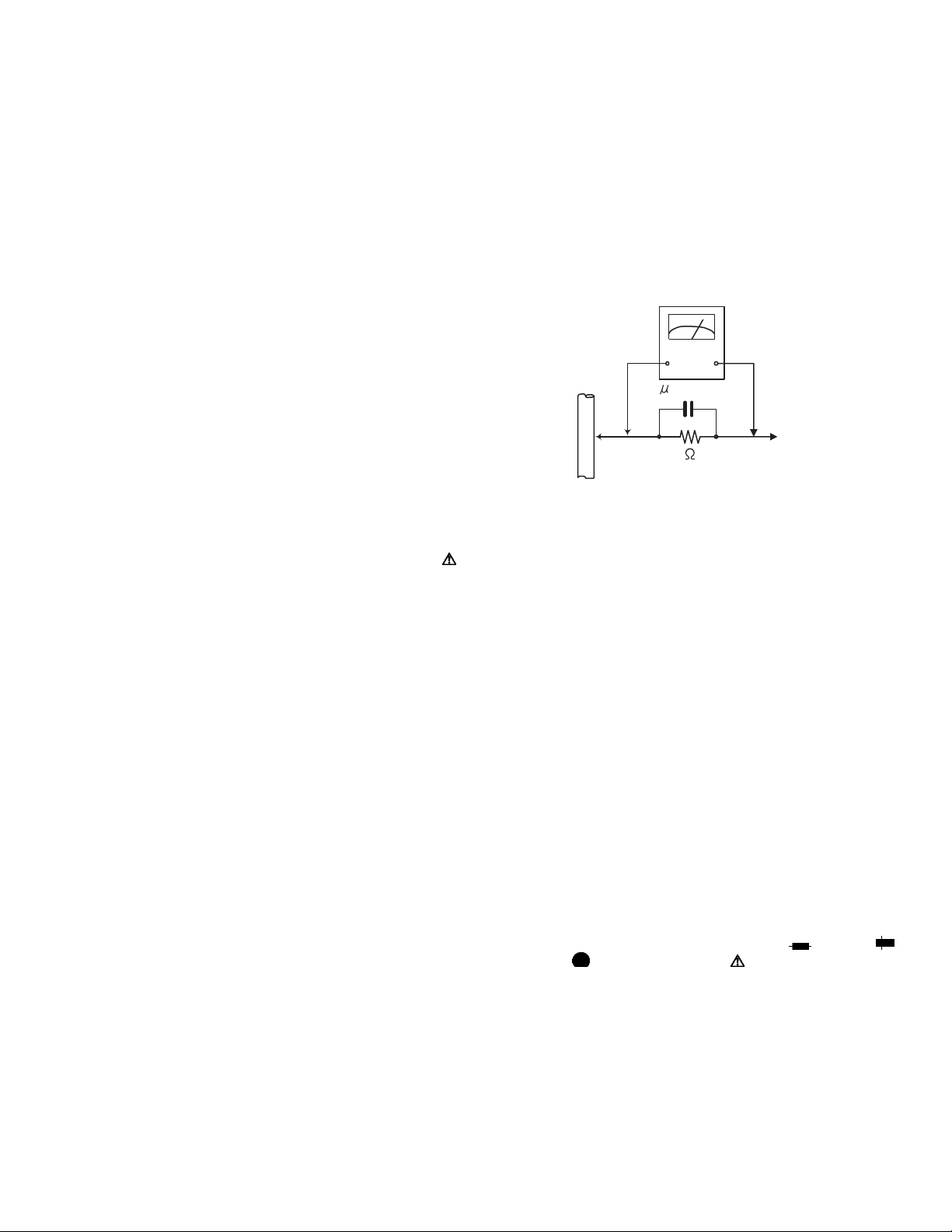
• Alternate check method
Plug the AC line cord directly into the AC outlet. Use an
AC voltmeter having, 1,000Ω per volt or more sensitivity
in the following manner. Connect a 1,500Ω 10W resistor
paralleled by a 0.15µF AC-type capacitor between an ex-
posed metal part and a known good earth ground.
Measure the AC voltage across the resistor with the AC
voltmeter.
Move the resistor connection to each exposed metal
part, particularly any exposed metal part having a return
path to the chassis, and measure the AC voltage across
the resistor. Now, reverse the plug in the AC outlet and
repeat each measurement. Voltage measured any must
not exceed 0.75 V AC (r.m.s.). This corresponds to 0.5
mA AC (r.m.s.).
AC VOLTMETER
(Having 1000
ohms/volts,
or more sensitivity)
0.15 F AC TYPE
Place this
probe on
1500 10W
Good earth ground
1.2 Warning
(1) This equipment has been designed and manufactured to
meet international safety standards.
(2) It is the legal responsibility of the repairer to ensure that
these safety standards are maintained.
(3) Repairs must be made in accordance with the relevant
safety standards.
(4) It is essential that safety critical components are replaced
by approved parts.
(5) If mains voltage selector is provided, check setting for local
voltage.
1.3 Caution
Burrs formed during molding may be left over on some parts
of the chassis.
Therefore, pay attention to such burrs in the case of preforming repair of this system.
1.4 Critical parts for safety
In regard with component parts appearing on the silk-screen
printed side (parts side) of the PWB diagrams, the parts that are
printed over with black such as the resistor ( ), diode ( )
and ICP ( ) or identified by the " " mark nearby are critical
for safety. When replacing them, be sure to use the parts of the
same type and rating as specified by the manufacturer.
(This regulation dose not Except the J and C version)
each exposed
metal part.
(No.MB350)1-3
Page 4
1.5 Preventing static electricity
Electrostatic discharge (ESD), which occurs when static electricity stored in the body, fabric, etc. is discharged, can destroy the laser
diode in the traverse unit (optical pickup). Take care to prevent this when performing repairs.
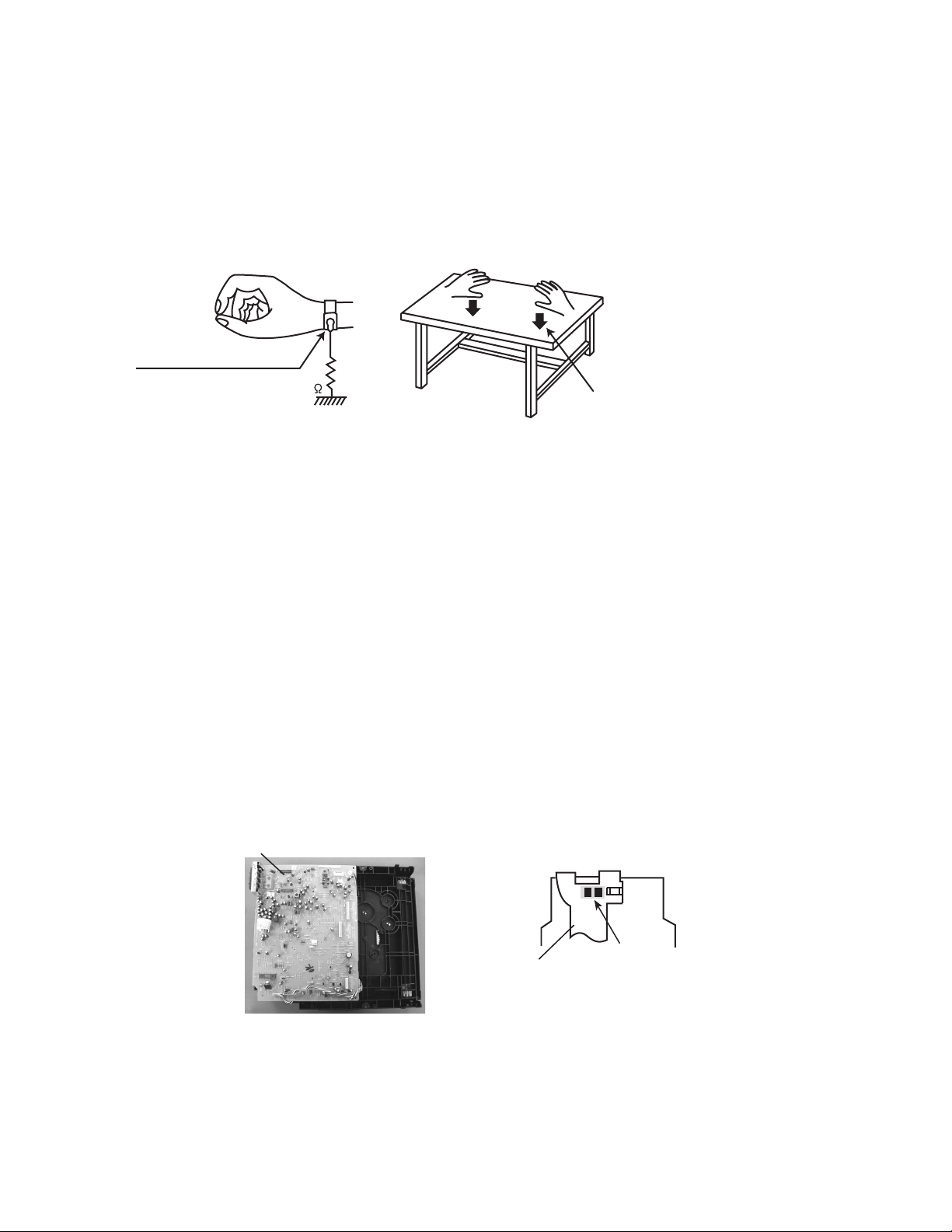
1.5.1 Grounding to prevent damage by static electricity
Static electricity in the work area can destroy the optical pickup (laser diode) in devices such as laser products.
Be careful to use proper grounding in the area where repairs are being performed.
(1) Ground the workbench
Ground the workbench by laying conductive material (such as a conductive sheet) or an iron plate over it before placing the
traverse unit (optical pickup) on it.
(2) Ground yourself
Use an anti-static wrist strap to release any static electricity built up in your body.
(caption)
Anti-static wrist strap
1M
Conductive material
(conductive sheet) or iron palate
(3) Handling the optical pickup
• In order to maintain quality during transport and before installation, both sides of the laser diode on the replacement optical
pickup are shorted. After replacement, return the shorted parts to their original condition.
(Refer to the text.)
• Do not use a tester to check the condition of the laser diode in the optical pickup. The tester's internal power source can easily
destroy the laser diode.
1.6 Handling the traverse unit (optical pickup)
(1) Do not subject the traverse unit (optical pickup) to strong shocks, as it is a sensitive, complex unit.
(2) Cut off the shorted part of the flexible cable using nippers, etc. after replacing the optical pickup. For specific details, refer to the
replacement procedure in the text. Remove the anti-static pin when replacing the traverse unit. Be careful not to take too long a
time when attaching it to the connector.
(3) Handle the flexible cable carefully as it may break when subjected to strong force.
(4) I t is not possible to adjust the semi-fixed resistor that adjusts the laser power. Do not turn it.
1.7 Attention when traverse unit is decomposed
*Please refer to "Disassembly method" in the text for the pickup unit.
• Apply solder to the short land sections before the flexible wire is disconnected from the connecto on the servo board. (If the flexible
wire is disconnected without applying solder, the pickup may be destroyed by static electricity.)
• In the assembly, be sure to remove solder from the short land sections after connecting the flexible wire.
CD changer
unit
1-4 (No.MB350)
Flexible cable
Soldering
Page 5
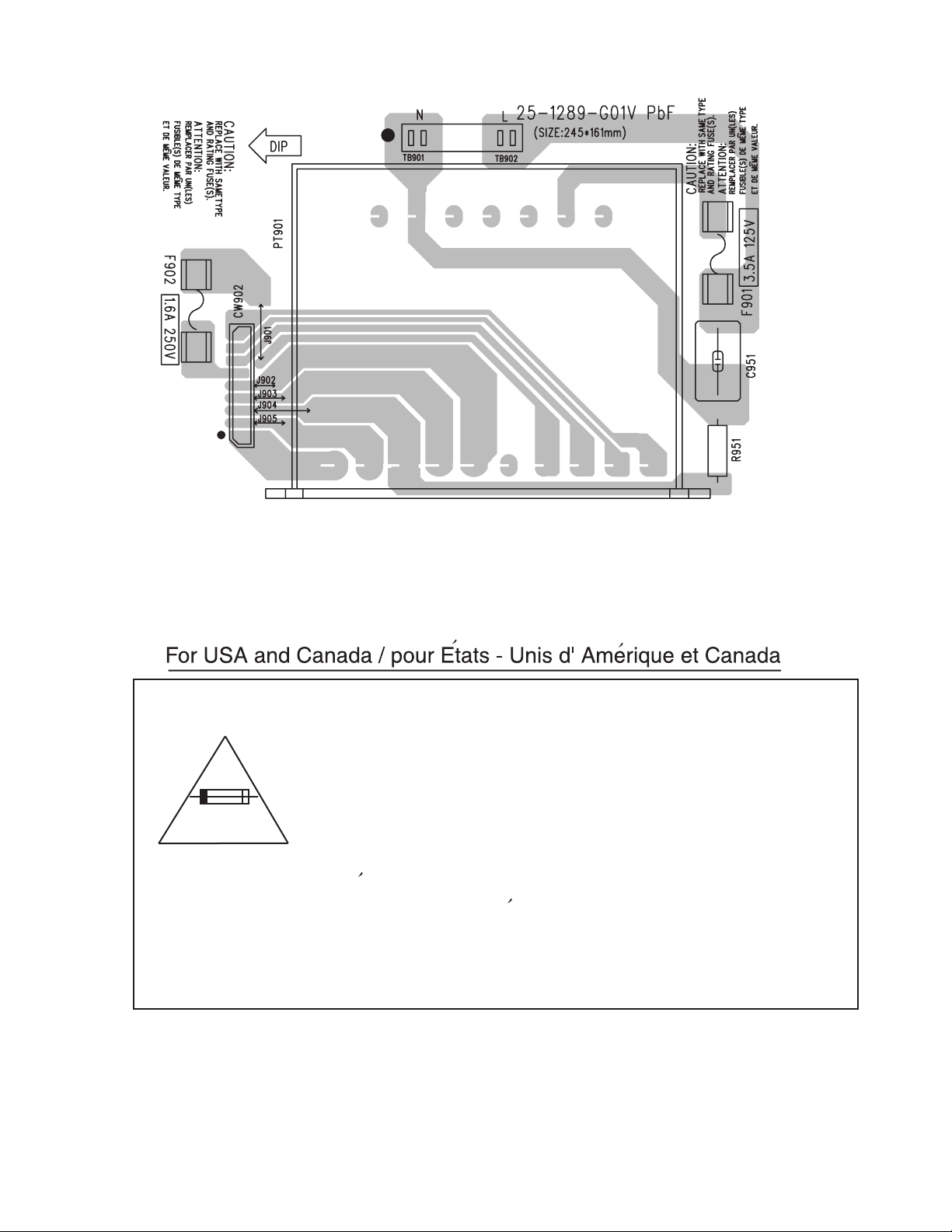
1.8 Importance administering point on the safety
Caution: For continued protection against risk of
fire, replace only with same type 3.5A/125V for
F901 and 1.6A/250V for F902. This symbol
specifies type of fast operating fuse.
Precaution: Pour eviter risques de feux, remplacez
le fusible de surete de F901 comme le meme type
que 3.5A/125V et F902 que 1.6A/250V .
Ce sont des fusibles suretes qui functionnes rapide.
^
(No.MB350)1-5
Page 6

SECTION 2
SPECIFIC SERVICE INSTRUCTIONS
This service manual does not describe PRECAUTION.
1-6 (No.MB350)
Page 7
SECTION 3
DISASSEMBLY
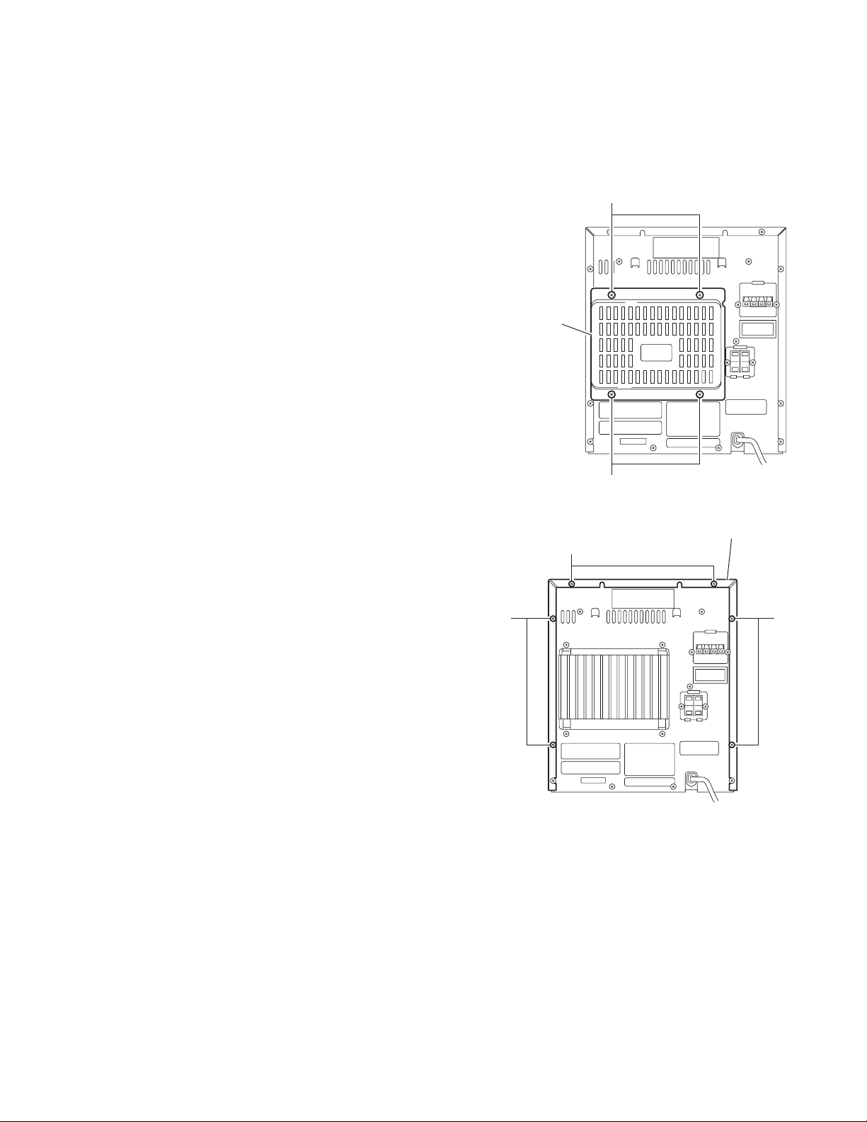
3.1 Main body
3.1.1 Removing the metal cover/ rear cover
(See Fig.1 to 5)
(1) Remove the four screws A on the back of the body.
(2) Remove the six screws B on the back of the body.
(3) Remove the four screws C and the two screws D on both
sides of the body.
(4) Move the metal covers in the direction of the arrow with
pulling them sideways, and release two joints a and six
joints b.
A
Rear cover
A
Fig.1
Metal cover
B
BB
Fig.2
(No.MB350)1-7
Page 8
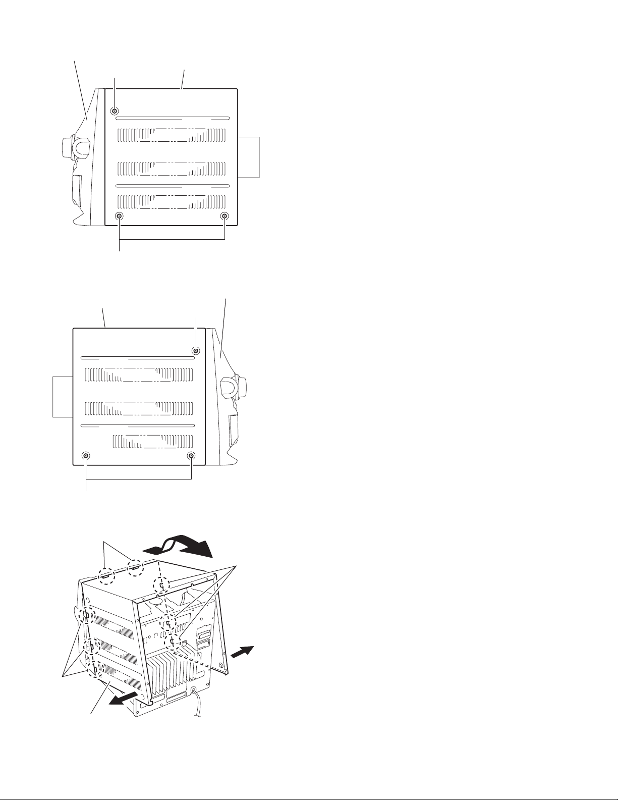
Front panel assembly
D
C
Metal cover
Metal cover
Fig.3
Front panel assembly
D
C
b
Metal cover
1-8 (No.MB350)
Fig.4
a
b
Fig.5
Page 9
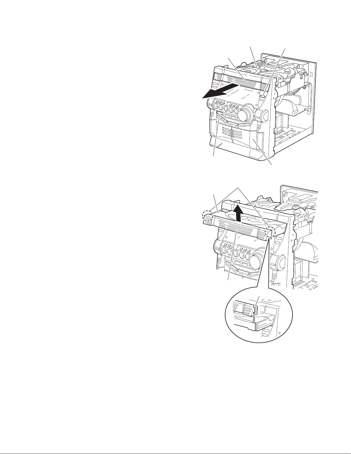
3.1.2 Removing the CD fitting
(See Fig.6 to 8)
• Prior to performing the following procedure, remove the metal
cover/ rear cover.
Caution:
For protecting the CD fitting from damage, remove it before detaching the CD changer mechanism unit.
(1) Push STANDBY/ON key to turn on the power.
(2) Push CD tray eject key.
(3) Move the CD fitting in the direction of the arrow to release
two joints d of the CD tray.
(4) Push STANDBY/ON key to close the tray.
3.1.3 Removing the CD fitting
(See Fig.7 to 9)
[How to eject the CD tray without turning on the power]
• Prior to performing the following procedure, remove the metal
cover/ rear cover.
(1) Turn the loading pulley gear on the bottom of the CD
changer mechanism unit (part e) as shown in the figure to
move the CD tray frontward.
(2) Move the CD fitting in the direction of the arrow to release
two joints d.
(3) Push and close the CD tray.
CD changer mechanism unit
CD fitting
STANDBY / ON key
Fig.6
d
CD tray
CD tray eject key
Front panel assembly
CD fitting
d
Fig.7
(No.MB350)1-9
Page 10

CD changer mechanism unit
CD tray
STANDBY / ON key
Fig.8
CD changer mechanism unit
CD tray eject key
Front panel assembly
Main board
e
Loading pullygear
Fig.9
1-10 (No.MB350)
Page 11

3.1.4 Removing the CD changer mechanism unit
(See Fig.10 to 14)
• Prior to performing the following procedure, remove the metal
cover/ rear cover and the CD fitting.
(1) From the bottom of the CD changer mechanism unit, dis-
connect the wire from connector CN401
on the main board.
CN205
(2) Disconnect the card wire from connector CN403, CN201
and CN601 on the main board.
(3) From the back of the body, remove the four screws E at-
taching the CD changer mechanism unit.
(4) From the back of the body, remove the four screws F at-
taching the CD changer mechanism unit.
(5) Pulling the rear panel backward, move the CD changer
mechanism unit in the direction of the arrow and remove.
, CN402 and
Main board
CN205
CD changer mechanism unit
CN402
CN401
Fig.10
CD changer mechanism unit
CN201
CN403
CN601
Main board
Rear panel
Fig.11
(No.MB350)1-11
Page 12

E
Rear panel
Fig.12
CD changer mechanism unit
F
E
Front panel assembly
Rear panel
Rear panel
Fig.13
CD changer mechanism unit
F
Front panel assembly
Fig.14
1-12 (No.MB350)
Page 13

3.1.5 Removing the power board
(See Fig.15 to 19)
• Prior to performing the following procedure, remove the metal
cover/ rear cover, the CD fitting and the CD changer mechanism unit.
(1) Disconnect the wire from connector CN903
the power board.
(2) Disconnect the card wire from connector CW601
power board.
(3) From the back of the body, remove the four screws G and
the three screws H attaching the power board.
(4) Release the two tabs f from the notch of the rear panel.
Move the power board in the direction of the arrow and remove frontward.
(5) From the bottom of the power board, remove the four
screws J attaching the heat sink.
(6) Remove the two screws K attaching the heat sink.
and CN202 on
on the
Rear panel
Power board
CW601
CN903
G
G
CN202
Fig.15
Rear panel
H
Fig.16
(No.MB350)1-13
Page 14

Raer panel
f
Heat sink
Power board
Heat sink
Power board
Fig.17
J
J
Fig.18
Power board
1-14 (No.MB350)
Heat sink
Fig.19
K
Page 15

3.1.6 Removing the transformer board
(See Fig.20 to 23)
• Prior to performing the following procedure, remove the metal
cover/ rear cover, the CD fitting and the CD changer mechanism unit.
(1) Disconnect the wire from connector CN903
the power board.
(2) From the back of the body, remove the four screws L at-
taching the rear panel.
(3) Remove the cord clamp in the direction of the arrow.
(4) From the base chassis, remove the four screws M attach-
ing the transformer.
(5) If necessary, unsolder the power cord and the wire extend-
ing from the power transformer assembly.
Rear panel
Power board
and CN202 on
Base chassis
Transformer board
Cord clamp
Fig.22
Transformer
CN903
CN202
Fig.20
MM
Transformer board
Fig.23
Rear panel
L
Fig.21
(No.MB350)1-15
Page 16

3.1.7 Removing the front panel assembly
(See Fig.24 to 27)
• Prior to performing the following procedure, remove the metal
cover, the CD fitting and the CD changer mechanism unit.
(1) Disconnect the wire from connector CN202 on the power
board.
(2) Disconnect the earth wire connected to the main base
chassis.
(3) From the bottom of the body, remove the screw N attaching
the front panel assembly.
(4) From each side of the body, remove the two screws P at-
taching the front panel assembly.
(5) Release joints g on each side of the body using a screw-
driver. Remove the front panel assembly frontward.
N
Rear panel
Front panel assembly
Fig.24
Power board
CN202
Side panel (L)
Fig.26
Front panel assembly
Side panel (R)
PP
g
Fig.27
1-16 (No.MB350)
Earth wire
Fig.25
Page 17

3.1.8 Removing the LCD board, CD tray eject switch board, REC select switch board and Operation board
(See Fig.28 , 29)
• Prior to performing the following procedure, remove the front
panel assembly.
(1) Pull out the volume knob on the front panel assembly.
(2) Remove the twenty-six screws Q attaching the LCD board,
CD tray eject switch board, REC select switch board and
Operation board.
Volume knob
CD tray eject
switch board
Q
Front panel assembly
Fig.28
LCD board
REC select
switch board
Q
3.1.9 Removing the cassette mechanism assembly
(See Fig.30)
• Prior to performing the following procedure, remove the front
panel assembly.
(1) Remove the six screws R attaching the cassette mecha-
nism assembly.
Q
Q
Q
Operation board
Fig.29
Q
Q
R
RR
R
Cassette mechanism assembly
Fig.30
(No.MB350)1-17
Page 18

3.1.10 Removing the main board
(See Fig.31 to 33)
• Prior to performing the following procedure, remove the metal
cover/ rear cover, the CD fitting and the CD changer mechanism unit.
Caution:
Before disconnecting the card wire from connector CN701
the main board and the CD pickup board, make sure to solder
the short-circuit point on the CD pickup board. If you do not follow this instruction, the pickup may be damaged.
(1) Disconnect the wire from connector CW3
board under the main board.
(2) From the bottom of the CD changer mechanism unit, re-
move the four screws T attaching the main board.
(3) Move the main board as shown in Fig.32 and disconnect
the wire from the connector on the CD mechanism board.
(4) Solder the short-circuit point on the CD pickup board and
disconnect the card wire from the CD pickup board.
Caution:
When reattaching the main board, make sure to connect the
card wire to connector CN701
pickup board before unsoldering the short-circuit point.
on the main board and the CD
on the motor
on
Motor board
CW3
TT
Main board
CN701
Main board
CD changer
mechanism unit
CD pick up
board
Fig.31
CD mechanism
assembly
CD mechanism
assembly
CW3
Motor board
CD pickup board
Short-circuit point
Fig.32
Card wire
Short-circuit point
Fig.33
1-18 (No.MB350)
Page 19

3.1.11 Removing the CD changer mechanism assembly
(See Fig.34 to 35)
• Also remove the CD changer unit.
(1) Turn the CD changer mechanism cover base and remove
the screws d connecting the unit to the CD changer mechanism assembly.
(2) Removing four screws e retaining the CD mechanism hold-
er assembly.
Caution:
When replacing the CD changer mechanism assembly, be
sure not to mistake the positions of the silver color and copper
color spring.
CD changer
unit
CD changer
mechanism
assembly
d
Fig.34
e
( Green color )
e
( Green color )
Fig.35
e
( Red color )
e
( Red color )
(No.MB350)1-19
Page 20

3.1.12 Removing the CD pickup
r
(See Fig.36)
• Prior to performing the following procedures, remove the top
cover.
• Also remove the CD changer unit.
• Also remove the CD changer mechanism.
(1) Widen the section f.
(2) While keeping the section f wide open, push the section g
in the direction of the arrow to remove the shaft, and then
remove the CD pickup.
CD pickup
f
3.1.13 Replacing the loading motor and rotor belt of the CD changer
(See Fig .37)
• Prior to performing the following procedures, remove the top
cover.
• Also open the CD changer tray.
(1) Remove the two screws L retaining the CD changer tray
loading motor.
(2) Remove the two screws M retaining the gear plate and take
it out, after remove the rotor belt from the pulley.
g
Shaft
Fig.36
M
L
3.1.14 Replacing the CD turn table and removing the motor
(See Fig.38 )
• Prior to performing the following procedures, remove the top
cover.
• Also remove the CD changer unit.
(1) Remove the one screws retaining the CD (Turn table).
(2) Remove the two screws retaining the stopper brackets on
both sides of the CD changer unit.
(3) Remove the stopper brackets from both sides of the CD
changer unit.
(4) Pull out the CD tray from the CD changer unit, all the way
and lift the tray to remove.
(5) Remove the gear and after push out the tray motor locker
and pull out the tray motor from the CD tray.
1-20 (No.MB350)
Fig.37
Turn table motor
Motor locker
Obligue gea
Fig.38
Page 21

3.1.15 Removing the cassette deck main motor, and replacing the main belts
r
(See Fig.39 and 40)
• Prior to performing the following procedures, remove the top
cover and both sides board.
• Also remove the CD changer unit.
• Also remove the front panel assembly.
(1) Remove six screws Z retaining the cassette deck mecha-
nism. (Fig.39)
(2) Remove the cassette deck mechanism.
(3) Remove two screws t retaining the main motor from the
front side of the cassette deck.
Caution:
After attaching the main motor, check the orientation of
the motor and the polarity of the wires.
(4) From the backside of the cassette deck, remove the main
motor and two main belts.
Caution:
The lengths of the cassette A(playback only) and cassette B(record/play) main belts are different. When attaching the main belts, use the longer belt for cassette A.
Cassette deck mechanism
(Back side)
Cassette deck mechanism
(Front side)
t
Fig.39
Cassette deck main moto
3.1.16 Removing the leaf switches of the cassette deck mechanism
(See Fig. 39 and 41)
• Prior to performing the following procedures, remove the top
cover and both sides board.
• Also remove the CD changer unit.
• Also remove the front panel assembly.
(1) Remove the six screws Z that retain the cassette deck
mechanism. (Fig.39)
(2) Remove the cassette deck mechanism.
(3) Turn the cassette deck mechanism upside down.
(4) Remove the solder from around the leaf switches.
(5) Pull out the leaf switches from the front side of the cassette
deck mechanism.
Main belt
(For B cassette)
Fig.40
Solder side of leaf switch
Cassette deck mechanism
Fig.41
Main belt
(For A cassette)
(Back side)
(No.MB350)1-21
Page 22

3.1.17 Removing the cassette deck heads
(See Fig. 39 and 42)
• Prior to performing the following procedures, remove the top
cover and both sides board.
• Also remove the CD changer unit.
• Also remove the front panel assembly.
(1) Remove six screws Z that retain the cassette deck mecha-
nism. (Fig.39)
(2) Remove the cassette deck mechanism and place it so that
the front side faces up.
(3) Remove the solder from the bottom side of the head termi-
nal and disconnect the wire.
(4) Remove screws U that retains the head.
(5) Remove screws V that retains the head.
(6) Hold the head and slide it in the direction of the arrow to re-
move it.
3.1.18 Removing the 3-pin regulator and bridge diode
(See Fig. 43)
• Prior to performing the following procedures, remove the top
cover and both sides board.
Remove two screws A that connect the heat sink.
(1) Remove two screws A that connect the heat sink.
(2) Remove two screws W that connect the heat sink.
(3) Remove the solder fixing the the 3-pin terminal regulator
, Q608.
Q604
(4) Remove the solder fixing the 4-pin bridge diode (D614
D615).
PB Head
Cassette deck mechanism
(Front side)
V
U
VU
REC/PB Head
Fig.42
W
A
,
Fig.43
1-22 (No.MB350)
Page 23

3.2 Speaker
3.2.1 Removing the front cabinet
(See Fig.1, 2)
Caution:
Cover the product with cloth to avoid damage.
(1) Insert a screwdriver into the two slots h at the bottom of the
speaker and release the seven bosses on the inside of the
front panel assembly toward the front.
Caution:
The seven bosses are attached with adhesion bond. Cover the
product with cloth to avoid damage and release each boss
slowly.
Reference:
Also the speaker wire extending from the main speaker comes
off. Remove each speaker if necessary.
Front panel assembly
Boss
h
(Bottom)
Fig.1
3.2.2 Removing the sub speaker/speaker
(See Fig.3)
• Prior to performing the following procedure, remove the front
cabinet.
(1) Disconnect the wire from the two sub speaker terminals.
(2) Remove the two screws U attaching the sub speaker.
(3) Detach the speaker, which is attached with bond.
Boss
Speaker
Front panel assembly
Fig.2
Front cabinet
Boss
Sub speaker terminal
Sub speaker
U
Wier
Bond
Sub speaker terminal
Fig.3
U
(No.MB350)1-23
Page 24

3.2.3 Removing the main speaker
(See Fig.4)
• Prior to performing the following procedure, remove the front
cabinet.
(1) Remove the four screws V attaching the main speaker.
If necessary, disconnect the wire connected to the sub
speaker terminal and the speaker.
Speaker wire
VV
Main speaker
Fig.4
1-24 (No.MB350)
Page 25

SECTION 4
ADJUSTMENT
4.1 Measurement Instruments Required for Adjustment
(1) Low frequency oscillator
This oscillator should have a capacity to output 0dBs to
600Ω at an oscillation frequency of 50Hz-20kHz.
(2) Attenuator impedance : 600Ω
(3) Electronic voltmeter
(4) Frequency counter
(5) Wow & flutter meter
(6) Test tape
VT712 : For Tape speed and wow flutter ( 3kHz)
VT703 : For Head angle (10kHz)
(7) Blank tape
TYPE l : AC-225
TYPE ll : AC-514
(8) Torque gauge
For play and back tension forward; TW2111A
Reverse; TW2121A
Fast Forward and Rewind; TW2231A
(9) Test disc
CTS-1000(12cm)
GRG-1211(8cm)
(10) Jitter meter
4.2 Measurement conditons
Power supply voltage AC 120V (60Hz)
Measurement
output terminal
4.3 Radio Input signal
AM modulation frequency 400Hz
Modulation factor 30%
FM modulation frequency 1 kHz
Frequency displacement 22.5kHz
Speaker out
TP101
(Measuring for TUNER/ DECK/CD)
Dummy load 6Ω
4.5 Standard measurement position of volume and switch
Power Standby
(Light STANDBY Indicator)
Sound Turbo,A,BASS EX OFF
Sound mode OFF
Main VOL. 0 Minimum
Travers mecha set position Disc 1
Precautions for measurement
(1) Apply 30pF and 33kΩ to the IF sweeper output side and
0.082µ F and 100kΩ in series to the sweeper input side.
(2) The IF sweeper output level should be made as low as
possible within the adjustable range.
(3) Since the IF sweeper is a fixed device, there is no need
to adjust this sweeper.
(4) Since a ceramic oscillator is used, there is no need to
perform any MIX adjustment.
(5) Since a fixed coil is used, there is no need to adjust the
FM tracking.
(6) The input and output earth systems are separated. In
case of simultaneously measuring the voltage in both of
the input and output systems with an electronic voltmeter
for two channels, therefore, the earth should be connected particularly carefully.
(7) In the case of BTL connection amp., the minus terminal
of speaker is not for earthing. Therefore, be sure not to
connect any other earth terminal to this terminal. This
system is of an BTL system.
(8) For connecting a dummy resistor when measuring the
output, use the wire with a greater code size.
(9) Whenever any mixed tape is used, use the band pass fil-
ter (DV-12).
4.4 Frequency Range
AM 530kHz - 1710kHz
FM 87.5MHz - 108MHz
(No.MB350)1-25
Page 26

4.6 Arrangement of adjusting positions
4.6.1 Tape recorder section
Items
Head azimuth
alignments
Measurement
conditions
Test tape
: VT703 (10kHz)
Measurement
output terminal
: Left and Right
speaker output
(6-ohm loaded)
or
H/P output
(32-ohm loaded)
Cassette deck mechanism
PB Head
(Deck-A)
Head azimuth screw
(Forward side)
Head azimuth screw
(Reverse side)
(Front side)
Head azimuth screw
(Forward side)
Measurement method
1. Playback the test tape VT703 (10KHz) or
equivalent.
2. Adjust the head azimuth screw to obtain
maximum
output and both output of L / R is in 3dB.
3.Put on the screw lock paint after alignments.
REC/PB Head
(Deck-B)
Head azimuth screw
(Reverse side)
Standard
values
Maximum
output
Adjusting
positions
Adjust the
head azimuth
screw only
when the head
has been
changed.
Bias frequency
alignment
4.6.2 Tuner section
Items
AM Tracking
alignments
AM IFT
alignments
Test tape
: TYPE I AC-514
Measurement
output terminal
: E. head terminal
(CN308 8-Pin)
Measurement
conditions
Input signal
: 530kHz
600kHz
Adjustment point
: Antenna coil (L2)
Input signal
: 530kHz
Adjustment point
: IFT (T1)
1. Insert the recording tape in deck-B.
2. Starting the recording.
3. Adjust the oscillation frequency to
80kHz+/-3kHz by core of oscillation coil of L301.
Measurement method
1. Set the Signal Generator signal to 530KHz the
feed to Loop Antenna.
2. Receiving the signal and the adjust the OSC
coil (L2) obtain the V.T is 1.40V +/-0.05V.
3. Change the receiving frequency to
600KHz (603KHz).
4. Adjust the Antenna coil ( L2 ) obtain maximum
sensitivity.
(Adjust the SSG output to out of AGC range.)
1. Set the receiving frequency to 530KHz.
2. Feed the 450KHz signal to AM antenna input.
3.Adjust the IFT Block T1 obtain to maximum
output.
(Adjust the SSG output to out of AGC range.)
80kHz+/-3kHz
Standard
values
V..T
:1.40V+/-0.05V
Maximum
sensitivity
Maximum
output
Use the HighImpedance
Probe or
Frequency
counter input.
Adjusting
positions
Adjust the OSC
coil only when
the AM coil block
has been
changed.
Adjust the IFT
only when the
IFT block has
been changed.
Note: The adjustment of CD section is not required.
1-26 (No.MB350)
Page 27

TROUBLESHOOTING
5.1 Flow of functional operation until TOC read
Power ON
Play Key
SECTION 5
Slider turns REST
SW ON.
Automatic tuning
of TE offset
Check Point
Confirm that the voltage at the pin5
of CN602 is "H"\"L"\"H".
Tracking error waveform at TOC reading
Approx.3sec
Tracking
servo
off states
Automatic measurement
of TE amplitude and
automatic tuning of
TE balance
VREF
pin 20 of
IC611(TE)
Approx
0.3V
Disc states
to rotate
Tracking
servo
on states
Disc to be
braked to stop
TOC reading
finishes
500mv/div
2ms/div
Fig-1
Laser ON
Detection of disc
Automatic tuning of
Focus offset
Automatic measurement of
Focus S-curve amplitude
Disc is rotated
Focus servo ON
(Tracking servo ON)
Automatic measurement of
Tracking error amplitude
Automatic tuning of
Tracking error balance
Check that the voltage at the
pin40 of IC601 is + 5V?
Confirm that the Focus error
S-cuve signal at the pin32 of
IC601 is approx.2Vp-p
Confirm that the signal from
pin24 IC601 is 0V as a
accelerated pulse during
approx.400ms.
Confirm the waveform of
the Tracking error signal.
at the pin 20 of IC611 (R643)
(See fig-1)
Automatic tuning of
Focus error balance
Automatic tuning of
Focus error gain
Automatic tuning of
Tracking error gain
TOC reading
Play a disc
Confirm the eys-pattern
at the lead of Pin 5 of IC 611
(No.MB350)1-27
Page 28

5.2 Maintenance of laser pickup
(1) Cleaning the pick up lens
Before you replace the pick up, please try to clean the lens
with a alcohol soaked cotton swab.
(2) Life of the laser diode
When the life of the laser diode has expired, the following
symptoms will appear.
• The level of RF output (EFM output : ampli tude of eye
pattern) will below.
5.3 Replacement of laser pickup
Turn off the power switch and, disconnect the
power cord from the ac outlet.
Replace the pickup with a normal one.(Refer
to "Pickup Removal" on the previous page)
Is the level of
RFOUT under
0.48V 0.1Vp-p?
NO
Replace it.
YES
O.K
(3) Semi-fixed resistor on the APC PC board
The semi-fixed resistor on the APC printed circuit board
which is attached to the pickup is used to adjust the laser
power. Since this adjustment should be performed to
match the characteristics of the whole optical block, do not
touch the semi-fixed resistor.
If the laser power is lower than the specified value, the laser diode is almost worn out, and the laser pickup should
be replaced.
If the semi-fixed resistor is adjusted while the pickup is
functioning normally, the laser pickup may be damaged
due to excessive current.
Plug the power cord in, and turn the power on.
At this time, check that the laser emits for
about 3seconds and the objective lens moves
up and down.
Note: Do not observe the laser beam directly.
Play a disc.
Check the eye-pattern at pin 5 of IC611
Finish.
1-28 (No.MB350)
Page 29

(No.MB350)1-29
Page 30

Victor Company of Japan, Limited
AV & MULTIMEDIA COMPANY AUDIO/VIDEO SYSTEMS CATEGORY 10-1,1chome,Ohwatari-machi,Maebashi-city,371-8543,Japan
(No.MB350)
Printed in Japan
VPT
 Loading...