

Page 1
SERVICE MANUAL
COMPACT COMPONENT SYSTEM
MB36920056
MX-KC4
Area suffix
A ------------------------ Australia
UW ----------- Brazil,Mexico,Peru
UY ------------------------ Argentina
UJ ---------------------- U.S.Military
CA-MXKC4SP-MXKC4 SP-MXKC4
Lead free solder used in the board (material : Sn-Ag-Cu, melting point : 219 Centigrade)
TABLE OF CONTENTS
1 PRECAUTION. . . . . . . . . . . . . . . . . . . . . . . . . . . . . . . . . . . . . . . . . . . . . . . . . . . . . . . . . . . . . . . . . . . . . . . . . 1-3
2 SPECIFIC SERVICE INSTRUCTIONS . . . . . . . . . . . . . . . . . . . . . . . . . . . . . . . . . . . . . . . . . . . . . . . . . . . . . . 1-4
3 DISASSEMBLY . . . . . . . . . . . . . . . . . . . . . . . . . . . . . . . . . . . . . . . . . . . . . . . . . . . . . . . . . . . . . . . . . . . . . . . 1-5
4 ADJUSTMENT . . . . . . . . . . . . . . . . . . . . . . . . . . . . . . . . . . . . . . . . . . . . . . . . . . . . . . . . . . . . . . . . . . . . . . . 1-17
5 TROUBLESHOOTING . . . . . . . . . . . . . . . . . . . . . . . . . . . . . . . . . . . . . . . . . . . . . . . . . . . . . . . . . . . . . . . . . 1-17
COPYRIGHT © 2005 Victor Company of Japan, Limited
No.MB369
2005/6
Page 2
SPECIFICATION
Amplifier
Output Power 140 W per channel, min. RMS, driven into 6 Ω at 1kHz, with no
more than 10% total harmonic distortion (IEC 268-3)
Input Sensitivity/
Impedance (1 kHz)
Cassette Deck Section Frequency Response Type l (NORMAL) 63 Hz - 12 500 Hz
CD Player CD Capacity 3 CDs
Tuner FM Tuner 87.50 MHz - 108.00 MHz for A
Unit Dimensions 270 mm × 306 mm × 456 mm (W/H/D)
Speaker Specifications (each unit)
Type 3-way bass-reflex type
Speaker Unit Woofer 16 cm cone × 1
Power Handling Capacity 140 W
Impedance 6 Ω
Frequency Range 45 Hz - 22 000 Hz
Sound pressure level 87 dB/W·m
Dimensions 266 mm × 333 mm × 241 mm (W/H/D)
Mass Approx. 3.9 kg
AUX IN 400 mV/50 kΩ
Speaker terminals 6 Ω - 16 Ω
Phones 32 Ω - 1 kΩ
15 mW/ch output into 32 Ω
Wow And Flutter 0.15% (WRMS)
Dynamic Range 85 dB
Signal-To-Noise Ratio 85 dB
Wow And Flutter Unmeasurable
AM Tuner 522 kHz - 1710 kHz for A
530 kHz - 1710 kHz (at AM10 kHz channel space) for UW, UJ, UY
531 kHz - 1710 kHz (at AM9 kHz channel space) for UW, UJ, UY
Mass Approx. 8.6 kg
Mid 5cm cone × 1
Tweeter 2cm dome × 1
Power Specifications
Power Requirements AC 240V 50Hz for A
AC 110 V/127 V/220 V/230 V-240 V , adjustable with voltage selector, 50 Hz/60 Hz for UW, UJ, UY
Power Consumption 140 W (power on mode)
22 W (in Standby mode)
Design and specifications are subject to change without notice.
1-2 (No.MB369)
Page 3
SECTION 1
PRECAUTION
1.1 Safety Precautions
(1) This design of this product contains special hardware and
many circuits and components specially for safety purposes. For continued protection, no changes should be made
to the original design unless authorized in writing by the
manufacturer. Replacement parts must be identical to
those used in the original circuits. Services should be performed by qualified personnel only.
(2) Alterations of the design or circuitry of the product should
not be made. Any design alterations of the product should
not be made. Any design alterations or additions will void
the manufacturers warranty and will further relieve the
manufacture of responsibility for personal injury or property
damage resulting therefrom.
(3) Many electrical and mechanical parts in the products have
special safety-related characteristics. These characteristics are often not evident from visual inspection nor can the
protection afforded by them necessarily be obtained by using replacement components rated for higher voltage, wattage, etc. Replacement parts which have these special
safety characteristics are identified in the Parts List of Service Manual. Electrical components having such features
are identified by shading on the schematics and by ( ) on
the Parts List in the Service Manual. The use of a substitute
replacement which does not have the same safety characteristics as the recommended replacement parts shown in
the Parts List of Service Manual may create shock, fire, or
other hazards.
(4) The leads in the products are routed and dressed with ties,
clamps, tubings, barriers and the like to be separated from
live parts, high temperature parts, moving parts and/or
sharp edges for the prevention of electric shock and fire
hazard. When service is required, the original lead routing
and dress should be observed, and it should be confirmed
that they have been returned to normal, after reassembling.
(5) Leakage shock hazard testing
After reassembling the product, always perform an isolation check on the exposed metal parts of the product (antenna terminals, knobs, metal cabinet, screw heads,
headphone jack, control shafts, etc.) to be sure the product
is safe to operate without danger of electrical shock.Do not
use a line isolation transformer during this check.
• Plug the AC line cord directly into the AC outlet. Using a
"Leakage Current Tester", measure the leakage current
from each exposed metal parts of the cabinet, particularly any exposed metal part having a return path to the
chassis, to a known good earth ground. Any leakage current must not exceed 0.5mA AC (r.m.s.).
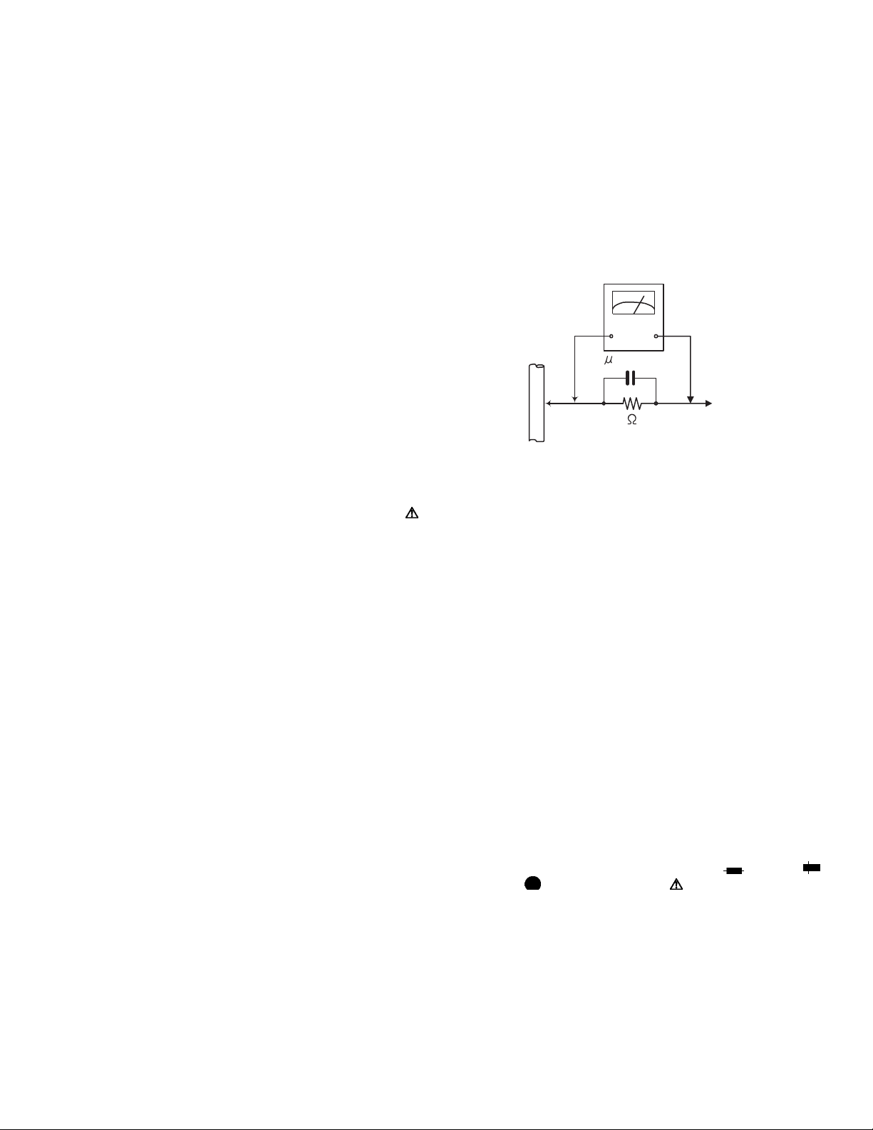
• Alternate check method
Plug the AC line cord directly into the AC outlet. Use an
AC voltmeter having, 1,000Ω per volt or more sensitivity
in the following manner. Connect a 1,500Ω 10W resistor
paralleled by a 0.15µF AC-type capacitor between an ex-
posed metal part and a known good earth ground.
Measure the AC voltage across the resistor with the AC
voltmeter.
Move the resistor connection to each exposed metal
part, particularly any exposed metal part having a return
path to the chassis, and measure the AC voltage across
the resistor. Now, reverse the plug in the AC outlet and
repeat each measurement. Voltage measured any must
not exceed 0.75 V AC (r.m.s.). This corresponds to 0.5
mA AC (r.m.s.).
AC VOLTMETER
(Having 1000
ohms/volts,
or more sensitivity)
0.15 F AC TYPE
Place this
probe on
1500 10W
Good earth ground
1.2 Warning
(1) This equipment has been designed and manufactured to
meet international safety standards.
(2) It is the legal responsibility of the repairer to ensure that
these safety standards are maintained.
(3) Repairs must be made in accordance with the relevant
safety standards.
(4) It is essential that safety critical components are replaced
by approved parts.
(5) If mains voltage selector is provided, check setting for local
voltage.
1.3 Caution
Burrs formed during molding may be left over on some parts
of the chassis.
Therefore, pay attention to such burrs in the case of preforming repair of this system.
1.4 Critical parts for safety
In regard with component parts appearing on the silk-screen
printed side (parts side) of the PWB diagrams, the parts that are
printed over with black such as the resistor ( ), diode ( )
and ICP ( ) or identified by the " " mark nearby are critical
for safety. When replacing them, be sure to use the parts of the
same type and rating as specified by the manufacturer.
(This regulation dose not Except the J and C version)
each exposed
metal part.
(No.MB369)1-3
Page 4

SECTION 2
SPECIFIC SERVICE INSTRUCTIONS
This service manual does not describe SPECIFIC SERVICE INSTRUCTIONS.
1-4 (No.MB369)
Page 5
SECTION 3
V
DISASSEMBLY
3.1 Disassembly of the main blocks of the set
Replacement of the fuses and the power IC.
3.1.1 Replacing the fuses
(See Fig.1)
• Prior to performing the following procedure, remove the left
side BOARD.
(1) Replace the fuses inside.
Caution:
Be sure to use fuses with the specified ratings.
3.1.2 Replacing the power IC
(See Fig.2)
• Prior to performing the following procedure, remove the top
cover.
(1) Remove the two screws A from the heat sink between the
power IC.
(2) Remove the solder fixing the power IC.
Fuse (F953)
T1.6AL 250V
Fig.1
W
Fuse (F951)
T3.15AL 250
Fuse (F952)
T1.6AL 250V
A
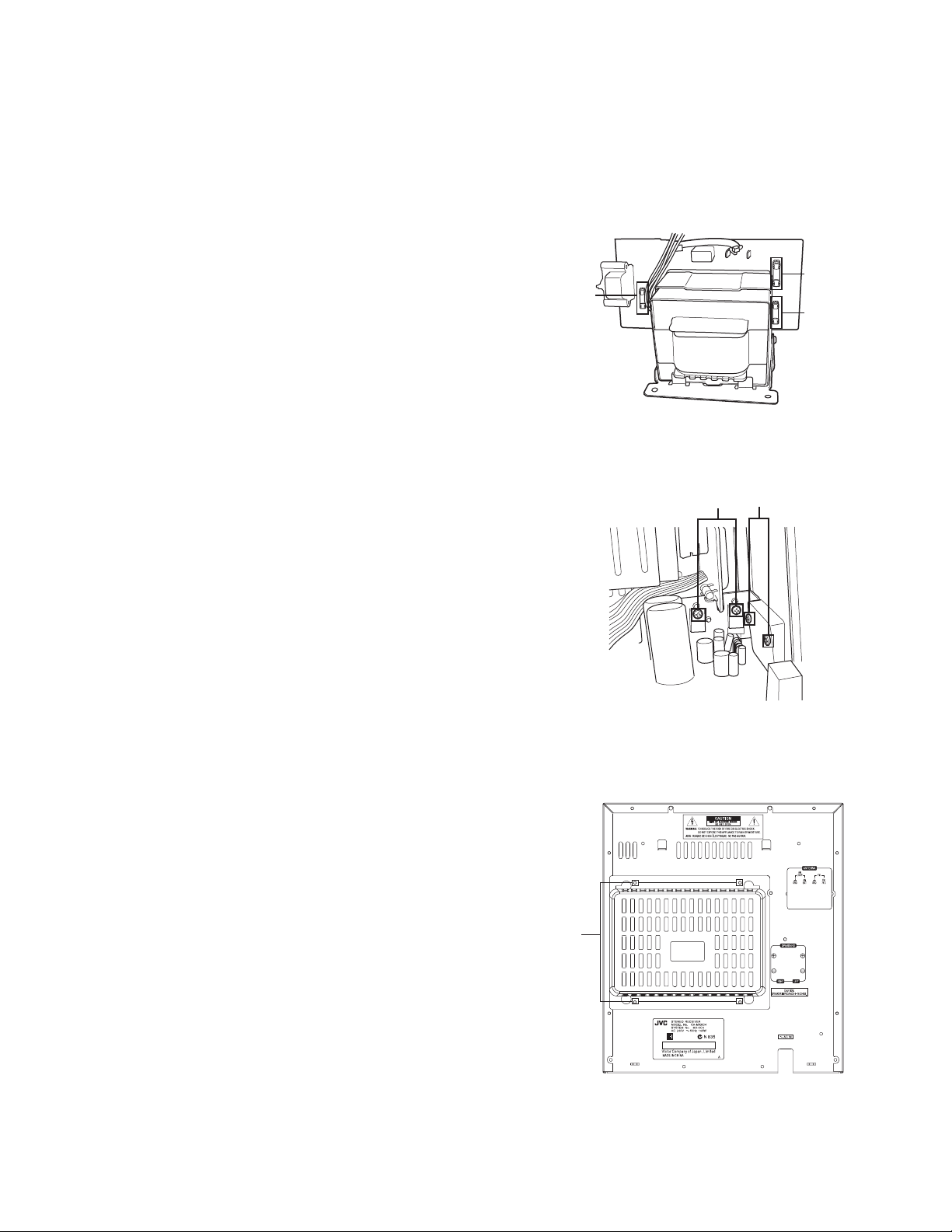
3.1.3 Replacing the heat sink cover
(See Fig.3)
(1) Remove four screws B from the rear panel.
(2) Pull the heat sink cover outward.
Fig.2
For CA-MXKC4 A
B
Fig.3
(No.MB369)1-5
Page 6
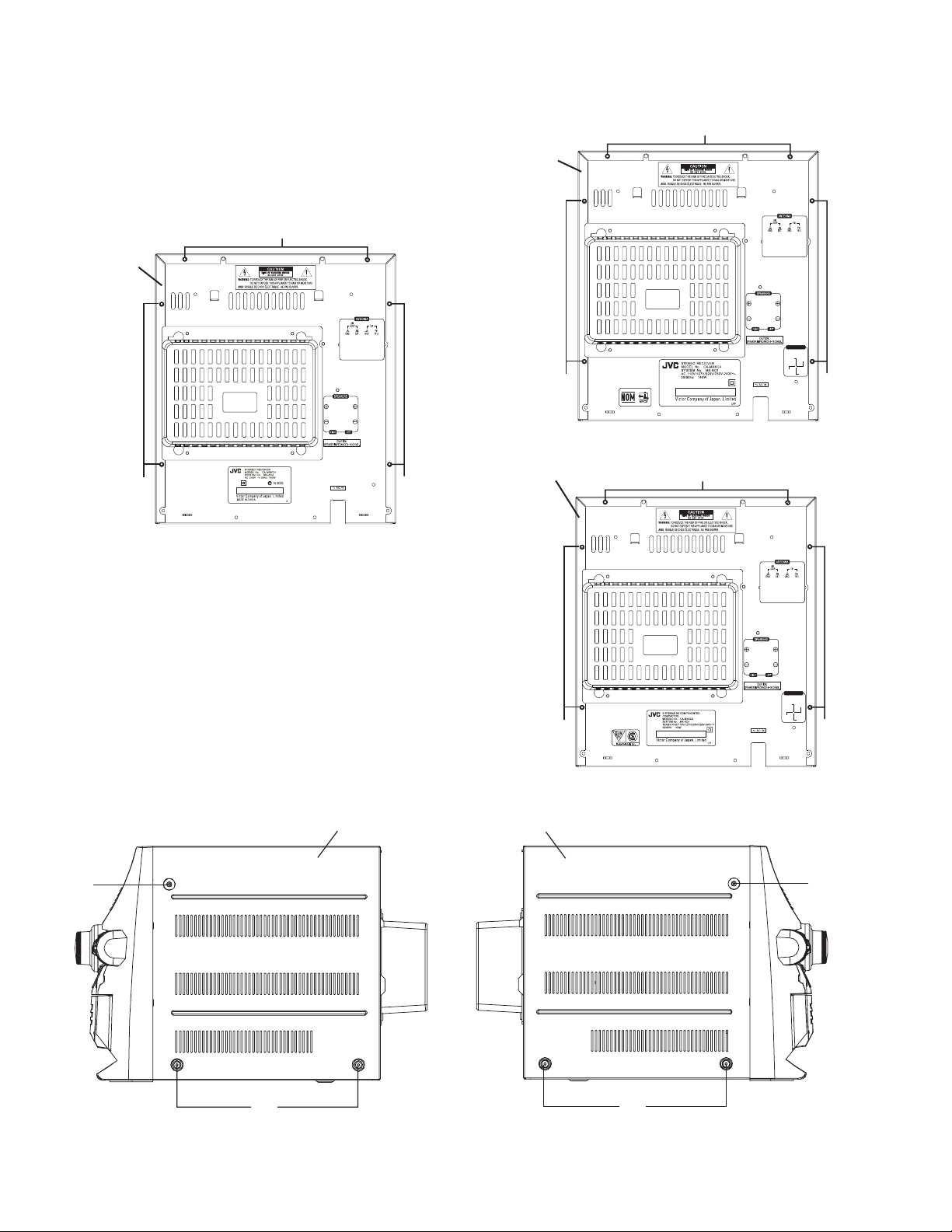
3.1.4 Removing the top cover
(See Fig.4 to 7)
(1) Remove six screws C that retain the top cover from the
panel rear of the body.
(2) Remove six screws D that retain the top cover from the two
sides of the body.
(3) Remove the top cover from the body by lifting it toward the
rear.
For CA-MXKC4 UW
Top cover
C
For CA-MXKC4 A
Top cover
C
Fig.4
C
220V
110V
250V
127V
-240V
C
C
Fig.5
C
Top cover
C
220V
110V
250V
127V
-240V
C
C
Fig.6
Right Front panel assembly
D
D
Left Front panel assembly
D
D
Fig.7
1-6 (No.MB369)
Page 7

3.1.5 Removing the CD changer unit
(See Fig.8 to 11)
• Prior to performing the following procedures, remove the top
cover.
Caution:
Although the CD mechanism unit can be removed without removing the CD tray panel, it is still recommended to remove it
in order to prevent damage.
• From the front panel side of this set, push in the sections
marked with arrows and pull out the CD tray toward the front.
• Remove the CD tray panel by pushing both of its extremities
upward in the direction of the arrows.
• Push the CD tray deep into the set.
(1) Disconnect the cord wires from the CD PCB CN703
and
CN203.
(2) From the rear of the set, remove two screws E, two screws
F and four screws G on the front panel left and right side.
(3) Handle the CD changer unit rear, take out the unit. CD tray
panel.
CD tray panel
For CA-MXKC4 A
E
Antenna
terminal
Fig.10
Fig.8
CD tray panel
Fig.9
G
Fig.11
(No.MB369)1-7
Page 8

3.1.6 Removing the front panel assembly
(See Fig.12 and 13)
• Prior to performing the following procedures, remove the top
cover.
• Also remove the CD changer unit.
(1) Disconnect the parallel wire and the cord wire from the con-
nectors CN701
(2) Remove one screws H retaining the front panel assembly
onto the bottom of the body.
(3) Remove two screws I on the left and right side of the set re-
taining the panel front from the bottom and then remove
then GND lug b that comes from the power amp and supply
PCB.
(4) Disengage the claws c on both sides of the front panel as-
sembly and then remove the assembly.
, CN101 on the power amp. PCB.
H
Fig.12
GND lug
a
Fig.13
GND lug
b
Claw
c
1-8 (No.MB369)
Page 9

3.2 Disassembly of units and assembly inside this set
3.2.1 Removing the MAIN PCB
(See Fig.14 and 15)
• Prior to performing the following procedures, remove the top
cover.
• Also remove the CD changer unit.
(1) Disconnect the wires from CN603A
on the PAIN PCB, which is located on the back side of the
CD changer unit.
(2) The four screws J that retain the CD PCB should be re-
moved.
(3) Remove the CD PCB by pulling it toward the side where the
is located.
CN601
(4) Using solder, short the CD pickup to connect to short
round.
Caution:
After re-connecting the wires, be sure to remove the
shorting solder from the GND connection.
(5) Disconnect the card wire from the connector CN601
main PCB and then remove the main PCB.
, CN603B and CN604
on the
CD PCB
J
PAIN PCB
J
Fig.14
J
CN601
Short round
Fig.15
(No.MB369)1-9
Page 10

3.2.2 Removing the CD changer mechanism assembly
(See Fig.16 and 17)
• Prior to performing the following procedures, remove the top
cover.
• Also remove the CD changer unit.
(1) Turn the CD changer mechanism cover base and remove
the screws d connecting the unit to the CD changer mechanism assembly.
(2) Removing four screws e retaining the CD mechanism hold-
er assembly.
Caution:
When replacing the CD changer mechanism assembly, be
sure not to mistake the positions of the silver color and copper
color spring.
CD changer
unit
CD changer
mechanism
assemb
ly
d
Fig.16
e
( Green color )
e
( Green color )
Fig.17
e
( Red color )
e
( Red color )
1-10 (No.MB369)
Page 11

3.2.3 Removing the CD pickup
(See Fig.18)
• Prior to performing the following procedures, remove the top
cover.
• Also remove the CD changer unit.
• Also remove the CD changer mechanism.
(1) Widen the section f.
(2) While keeping the section f wide open, push the section g
in the direction of the arrow to remove the shaft, and then
remove the CD pickup.
CD pickup
f
3.2.4 Replacing the loading motor and rotor belt of the CD changer
(See Fig .19)
• Prior to performing the following procedures, remove the top
cover.
• Also open the CD changer tray.
(1) Remove the two screws L retaining the CD changer tray
loading motor.
(2) Remove the two screws M retaining the gear plate and take
it out, after remove the rotor belt from the pulley.
g
Shaft
Fig.18
M
L
Fig.19
(No.MB369)1-11
Page 12

3.2.5 Replacing the CD turn table and removing the motor
r
(See Fig. 20)
• Prior to performing the following procedures, remove the top
cover.
• Also remove the CD changer unit.
(1) Remove the one screws N retaining the CD (Turn table).
(2) Remove the two screws O retaining the stopper brackets
on both sides of the CD changer unit.
(3) Remove the stopper brackets from both sides of the CD
changer unit.
(4) Pull out the CD tray from the CD changer unit, all the way
and lift the tray to remove.
(5) Remove the gear and after push out the tray motor locker
and pull out the tray motor from the CD tray.
3.2.6 Removing the cassette deck mechanism
(See Fig.21)
• Prior to performing the following procedures, remove the top
cover.
• Also remove the CD changer unit.
• Also remove the front panel assembly.
(1) Remove six screws Z retaining the cassette deck mecha-
nism.
Turn table motor
Motor locker
Obligue gea
Fig.20
Front panel
assembly
Fig.21
Z
Z
1-12 (No.MB369)
Page 13

3.2.7 Removing the key open PCB & the key REC PCB
y
(See Fig.22)
• Prior to performing the following procedures, remove the top
cover.
• Also remove the CD changer unit.
• Also remove the front panel assembly.
(1) Remove two screws P that retains the key open PCB.
(2) Remove three screws L that retains the key REC PCB.
3.2.8 Removing the display PCB
(See Fig.23)
• Prior to performing the following procedures, remove the top
cover.
• Also remove the CD changer unit.
• Also remove the front panel assembly.
(1) Remove six screws Q that retain the display PCB from the
back of the front panel unit.
3.2.9 Removing the switch PCB and sound mode and CD
function switch PCB
(See Fig.22 to 25)
• Prior to performing the following procedures, remove the top
cover.
• Also remove the CD changer unit.
• Also remove the front panel assembly.
(1) Pull out the volume control knob from the front of the front
panel assembly.(Fig.24)
(2) Remove six screws Q retaining the front panel assembly.
(3) Remove the control/FL PCB.
(4) Remove eleven screws R retaining the switch (key 1)
PCB.(Fig.22)
(5) Remove two screws S retaining the sound mode and CD
function (key 2) switch PCB.(Fig.23)
Front panel assembl
Volume knob
Fig.24
Front panel
assembly
key open
PCB
P
Front panel
assembly
olume
V
L
shaft
key REC
PCB
Fig.22
display
PCB
Q
Q
Fig.25
Fig.23
(No.MB369)1-13
Page 14

3.2.10 Removing the cassette deck main motor, and replacing the main belts
r
(See Fig.21, 26 and 27)
• Prior to performing the following procedures, remove the top
cover and both sides board.
• Also remove the CD changer unit.
• Also remove the front panel assembly.
(1) Remove six screws Z retaining the cassette deck mecha-
nism. (Fig.21)
(2) Remove the cassette deck mechanism.
(3) Remove two screws t retaining the main motor from the
front side of the cassette deck.
Caution:
After attaching the main motor, check the orientation of
the motor and the polarity of the wires.
(4) From the backside of the cassette deck, remove the main
motor and two main belts.
Caution:
The lengths of the cassette A(playback only) and cassette
B(record/play) main belts are different. When attaching the
main belts, use the longer belt for cassette A.
Cassette deck mechanism
(Back side)
Cassette deck mechanism
(Front side)
t
Fig.26
Cassette deck main moto
Main belt
(For B cassette)
Main belt
(For
Fig.27
A
cassette)
1-14 (No.MB369)
Page 15

3.2.11 Removing the leaf switches of the cassette deck mechanism
(See Fig. 21 and 28)
• Prior to performing the following procedures, remove the top
cover and both sides board.
• Also remove the CD changer unit.
• Also remove the front panel assembly.
(1) Remove the six screws Z that retain the cassette deck
mechanism. (Fig.21)
(2) Remove the cassette deck mechanism.
(3) Turn the cassette deck mechanism upside down.
(4) Remove the solder from around the leaf switches.
(5) Pull out the leaf switches from the front side of the cassette
deck mechanism.
3.2.12 Removing the cassette deck heads
(See Fig. 21 and 29)
• Prior to performing the following procedures, remove the top
cover and both sides board.
• Also remove the CD changer unit.
• Also remove the front panel assembly.
(1) Remove six screws Z that retain the cassette deck mecha-
nism. (Fig.21)
(2) Remove the cassette deck mechanism and place it so that
the front side faces up.
(3) Remove the solder from the bottom side of the head termi-
nal and disconnect the wire.
(4) Remove screws U that retains the head.
(5) Remove screws V that retains the head.
(6) Hold the head and slide it in the direction of the arrow to re-
move it.
PB Head
Solder side of leaf switch
Cassette deck mechanism
(Back side)
Fig.28
Cassette deck mechanism
(Front side)
V
U
VU
REC/PB Head
3.2.13 Removing the 3-pin regulator and bridge diode
(See Q604, Q608, D614, D615 and Fig.30)
• Prior to performing the following procedures, remove the top
cover and both sides board.
(1) Remove two screws A that connect the heat sink.
(2) Remove two screws W that connect the heat sink.
(3) Remove the solder fixing the the 3-pin terminal regulator
, Q608.
Q604
(4) Remove the solder fixing the 4-pin bridge diode (D614
D615).
Fig.29
W
,
Fig.30
A
(No.MB369)1-15
Page 16

3.2.14 Removing the power amp and supply PCB and the power trans PCB
V
A
(See Fig. 3, 30 to 33)
• Prior to performing the following procedures, remove the top
cover and CD changer unit.
(1) Remove four screws B from the rear panel. (Fig.3)
(2) Pull the heat sink cover outward.
(3) Remove four screws AA from the rear panel between the
heat sink holder.
Fuse (F953)
T1.6AL 250V
(4) Remove four screws YY that retains the rear panel, and
then remove the rear panel.
(5) Disconnect the parallel wires from the connectors FW951
on the power trans PCB.
(6) Remove screws Z that retain the power amp and supply
PCB and then remove the assembly.
(7) Remove the clamp of AC power cord from the chassis.
(8) Remove four screws that retain the power trans PCB and
then remove the assembly.
A
Fuse (F951)
T3.15AL 250
Fuse (F952)
T1.6AL 250V
Fig.31
For CA-MXKC4 A
Rear panel
YY
Fig.32
Power amp and
supply PCB
Chassis
Z
Fig.33
Clamp
1-16 (No.MB369)
Page 17

SECTION 4
ADJUSTMENT
This service manual does not describe ADJUSTMENT.
SECTION 5
TROUBLESHOOTING
This service manual does not describe TROUBLESHOOTING.
(No.MB369)1-17
Page 18

Victor Company of Japan, Limited
AV & MULTIMEDIA COMPANY AUDIO/VIDEO SYSTEMS CATEGORY 10-1,1chome,Ohwatari-machi,Maebashi-city,371-8543,Japan
(No.MB369)
Printed in Japan
VPT
 Loading...