

Page 1
MB434200510
SERVICE MANUAL
COMPACT COMPONENT SYSTEM
MX-KC2
Area suffix
UW ----------- Brazil,Mexico,Peru
UY ------------------------ Argentina
CA-MXKC2 SP-MXKC2SP-MXKC2
Lead free solder used in the board (material : Sn-Ag-Cu, melting point : 219 Centigrade)
TABLE OF CONTENTS
1 PRECAUTION. . . . . . . . . . . . . . . . . . . . . . . . . . . . . . . . . . . . . . . . . . . . . . . . . . . . . . . . . . . . . . . . . . . . . . . . . 1-3
2 SPECIFIC SERVICE INSTRUCTIONS . . . . . . . . . . . . . . . . . . . . . . . . . . . . . . . . . . . . . . . . . . . . . . . . . . . . . . 1-4
3 DISASSEMBLY . . . . . . . . . . . . . . . . . . . . . . . . . . . . . . . . . . . . . . . . . . . . . . . . . . . . . . . . . . . . . . . . . . . . . . . 1-5
4 ADJUSTMENT . . . . . . . . . . . . . . . . . . . . . . . . . . . . . . . . . . . . . . . . . . . . . . . . . . . . . . . . . . . . . . . . . . . . . . . 1-17
5 TROUBLESHOOTING . . . . . . . . . . . . . . . . . . . . . . . . . . . . . . . . . . . . . . . . . . . . . . . . . . . . . . . . . . . . . . . . . 1-17
COPYRIGHT © 2005 Victor Company of Japan, Limited
No.MB434
2005/10
Page 2
SPECIFICATION
Amplifier Output Power 50 W per channel, min. RMS, driven into 6 Ω at 1kHz, with no
more than 10% total harmonic distortion. (IEC 268-3)
Input Sensitivity/Impedance
(1 kHz)
Cassette Deck Section Frequency Response Type l (NORMAL) 63 Hz - 12 500 Hz
CD Player CD Capacity 3 CDs
Tuner FM Tuner : Tuning Range 87.5 MHz - 108.0 MHz(at AM10 kHz channel space)
Unit Dimensions 270 mm × 308 mm × 410 mm (W/H/D)
Speaker Specifications
(each unit)
Power Specifications Power Requirements AC 110 V - 127 V/220 V - 240 V , adjustable with voltage se-
AUX IN 400 mV/50 kΩ
Speaker terminals 6 Ω - 16 Ω
Phones 32 Ω - 1 kΩ
15 mW/ch output into 32 Ω
Wow And Flutter 0.15% (WRMS)
Dynamic Range 83 dB
Signal-To-Noise Ratio 85 dB
Wow And Flutter Unmeasurable
87.50 MHz - 108.00 MHz(at AM9 kHz channel space)
AM Tuner : Tuning Range 530 kHz - 1710 kHz (at AM10 kHzchannel space)
531 kHz - 1710 kHz (at AM9 kHzchannel space)
Mass Approx. 6.5 kg
Type 2-way bass-reflex type
Speaker Unit Woofer : 13 cm cone × 1
Tweeter : 5 cm cone × 1
Power Handling Capacity 50 W
Impedance 6 Ω
Frequency Range 45 Hz - 22 000 Hz
Sound pressure level 87 dB/W
Dimensions 205 mm × 308 mm × 209 mm (W/H/D)
Mass Approx. 2.9 kg
lector, 50 Hz/60 Hz
Power Consumption 110 W (power on mode)
13 W (in Standby mode)
1.2 W (in Eco mode)
·m
Design and specifications are subject to change without notice.
1-2 (No.MB434)
Page 3
SECTION 1
PRECAUTION
1.1 Safety Precautions
(1) This design of this product contains special hardware and
many circuits and components specially for safety purposes. For continued protection, no changes should be made
to the original design unless authorized in writing by the
manufacturer. Replacement parts must be identical to
those used in the original circuits. Services should be performed by qualified personnel only.
(2) Alterations of the design or circuitry of the product should
not be made. Any design alterations of the product should
not be made. Any design alterations or additions will void
the manufacturers warranty and will further relieve the
manufacture of responsibility for personal injury or property
damage resulting therefrom.
(3) Many electrical and mechanical parts in the products have
special safety-related characteristics. These characteristics are often not evident from visual inspection nor can the
protection afforded by them necessarily be obtained by using replacement components rated for higher voltage, wattage, etc. Replacement parts which have these special
safety characteristics are identified in the Parts List of Service Manual. Electrical components having such features
are identified by shading on the schematics and by ( ) on
the Parts List in the Service Manual. The use of a substitute
replacement which does not have the same safety characteristics as the recommended replacement parts shown in
the Parts List of Service Manual may create shock, fire, or
other hazards.
(4) The leads in the products are routed and dressed with ties,
clamps, tubings, barriers and the like to be separated from
live parts, high temperature parts, moving parts and/or
sharp edges for the prevention of electric shock and fire
hazard. When service is required, the original lead routing
and dress should be observed, and it should be confirmed
that they have been returned to normal, after reassembling.
(5) Leakage shock hazard testing
After reassembling the product, always perform an isolation check on the exposed metal parts of the product (antenna terminals, knobs, metal cabinet, screw heads,
headphone jack, control shafts, etc.) to be sure the product
is safe to operate without danger of electrical shock.Do not
use a line isolation transformer during this check.
• Plug the AC line cord directly into the AC outlet. Using a
"Leakage Current Tester", measure the leakage current
from each exposed metal parts of the cabinet, particularly any exposed metal part having a return path to the
chassis, to a known good earth ground. Any leakage current must not exceed 0.5mA AC (r.m.s.).
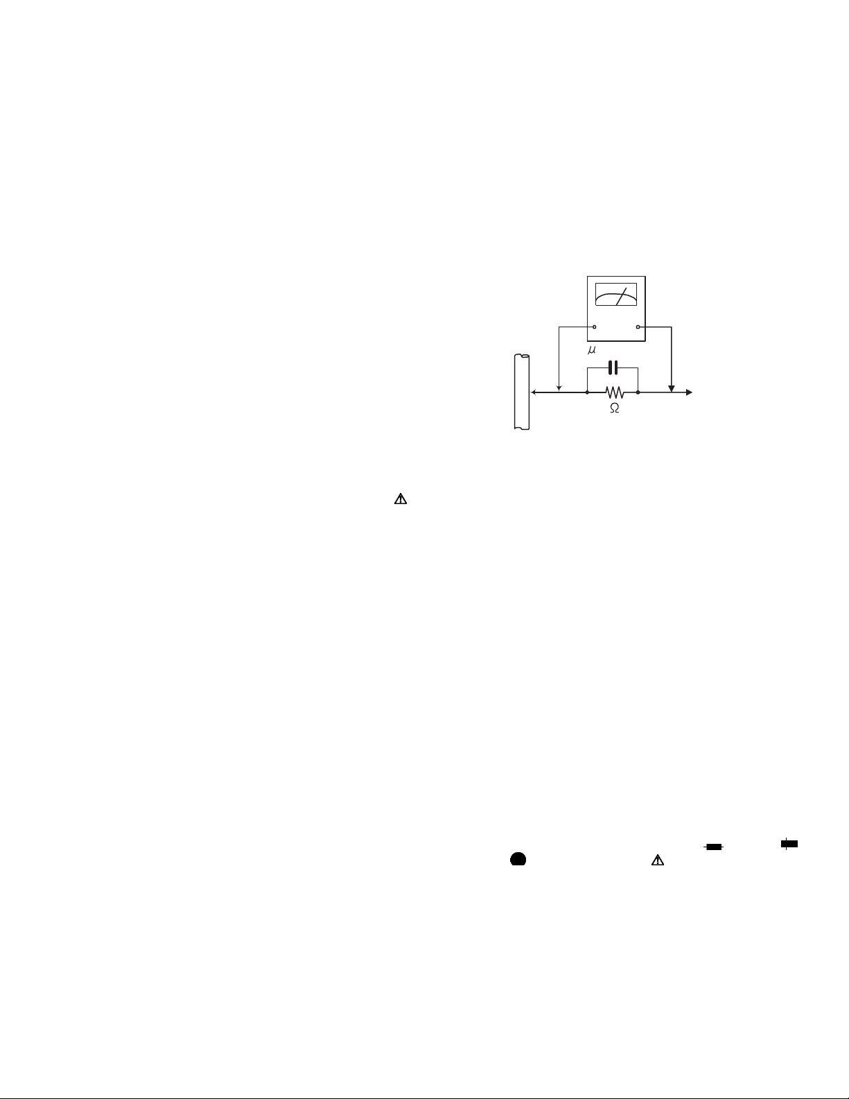
• Alternate check method
Plug the AC line cord directly into the AC outlet. Use an
AC voltmeter having, 1,000Ω per volt or more sensitivity
in the following manner. Connect a 1,500Ω 10W resistor
paralleled by a 0.15µF AC-type capacitor between an ex-
posed metal part and a known good earth ground.
Measure the AC voltage across the resistor with the AC
voltmeter.
Move the resistor connection to each exposed metal
part, particularly any exposed metal part having a return
path to the chassis, and measure the AC voltage across
the resistor. Now, reverse the plug in the AC outlet and
repeat each measurement. Voltage measured any must
not exceed 0.75 V AC (r.m.s.). This corresponds to 0.5
mA AC (r.m.s.).
AC VOLTMETER
(Having 1000
ohms/volts,
or more sensitivity)
0.15 F AC TYPE
Place this
probe on
1500 10W
Good earth ground
1.2 Warning
(1) This equipment has been designed and manufactured to
meet international safety standards.
(2) It is the legal responsibility of the repairer to ensure that
these safety standards are maintained.
(3) Repairs must be made in accordance with the relevant
safety standards.
(4) It is essential that safety critical components are replaced
by approved parts.
(5) If mains voltage selector is provided, check setting for local
voltage.
1.3 Caution
Burrs formed during molding may be left over on some parts
of the chassis.
Therefore, pay attention to such burrs in the case of preforming repair of this system.
1.4 Critical parts for safety
In regard with component parts appearing on the silk-screen
printed side (parts side) of the PWB diagrams, the parts that are
printed over with black such as the resistor ( ), diode ( )
and ICP ( ) or identified by the " " mark nearby are critical
for safety. When replacing them, be sure to use the parts of the
same type and rating as specified by the manufacturer.
(This regulation dose not Except the J and C version)
each exposed
metal part.
(No.MB434)1-3
Page 4

SECTION 2
SPECIFIC SERVICE INSTRUCTIONS
This service manual does not describe SPECIFIC SERVICE INSTRUCTIONS.
1-4 (No.MB434)
Page 5
SECTION 3
DISASSEMBLY
3.1 Disassembly of the main blocks of the set
Replacement of the fuses and the power IC
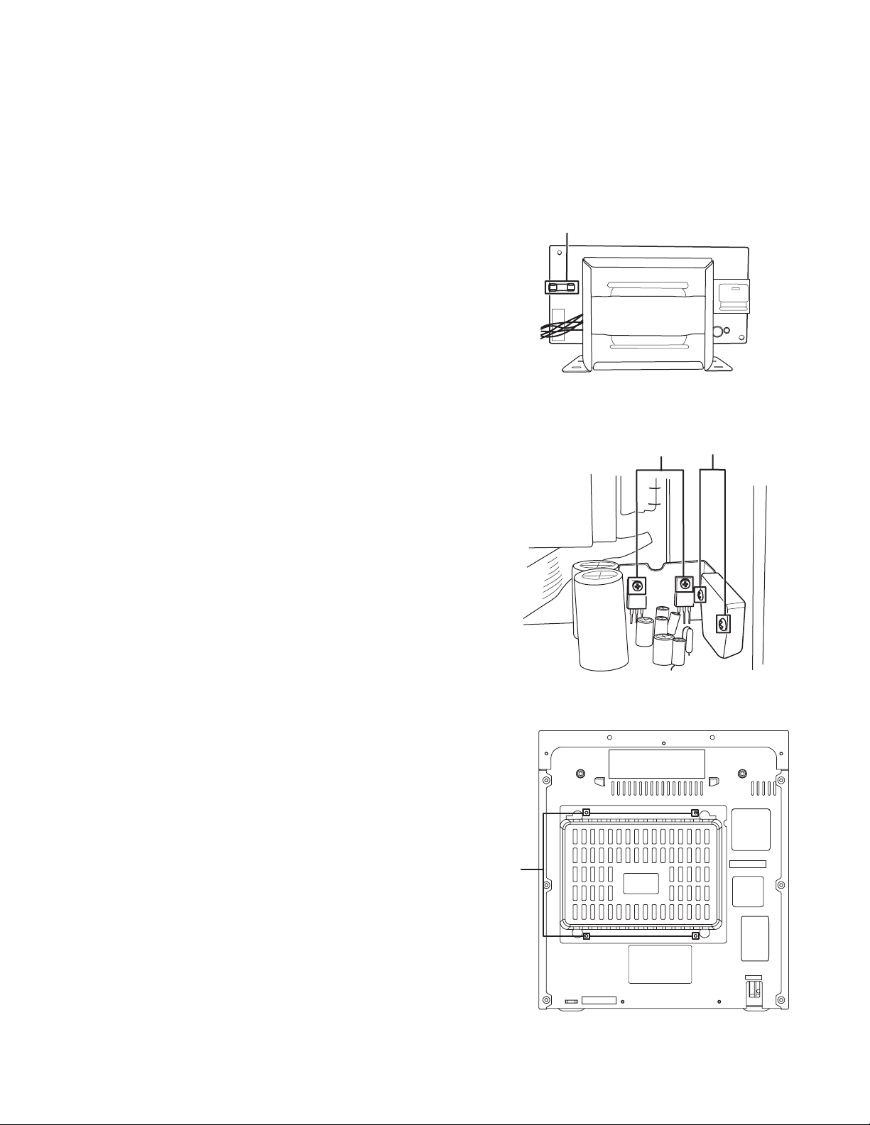
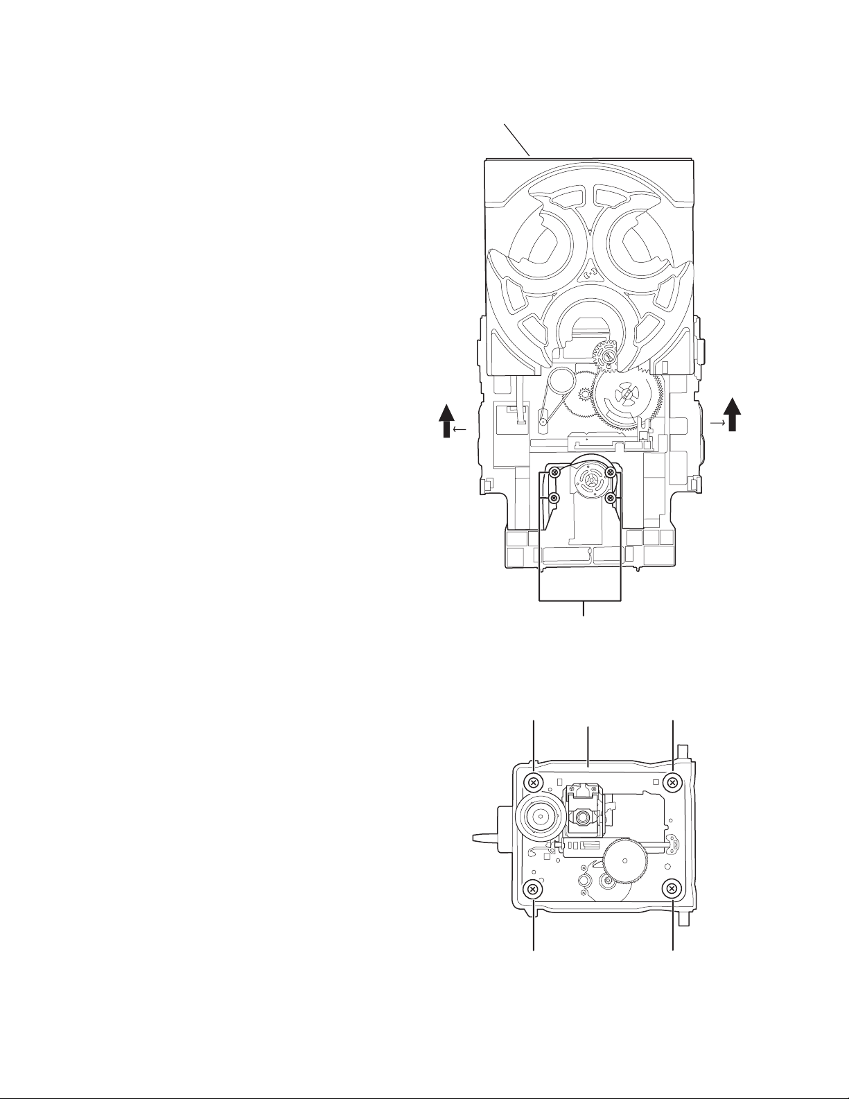
3.1.1 Replacing the fuses
(See Fig.1)
• Prior to performing the following procedure, remove the left
side board.
(1) Replace the fuses inside.
Caution:
Be sure to use fuses with the specified ratings.
3.1.2 Replacing the power IC
(See Fig.2)
• Prior to performing the following procedure, remove the top
cover.
(1) Remove the two screws A from the heat sink between the
power IC.
(2) Remove the solder fixing the power IC.
Fuse (F901)
1.6AL 250V
Fig.1
W
A
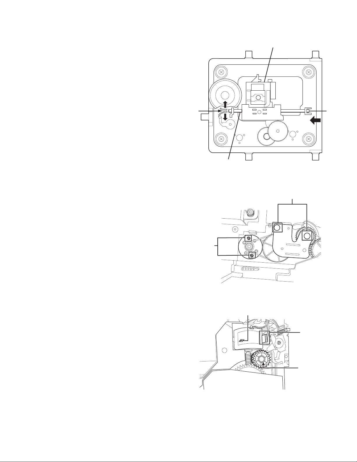
3.1.3 Replacing the heat sink cover
(See Fig.3)
(1) Remove four screws B from the rear panel.
(2) Pull the heat sink cover outward.
Fig.2
B
Fig.3
(No.MB434)1-5
Page 6
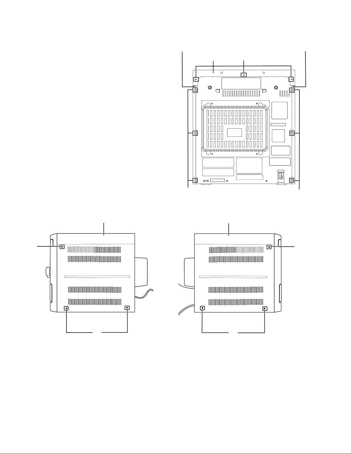
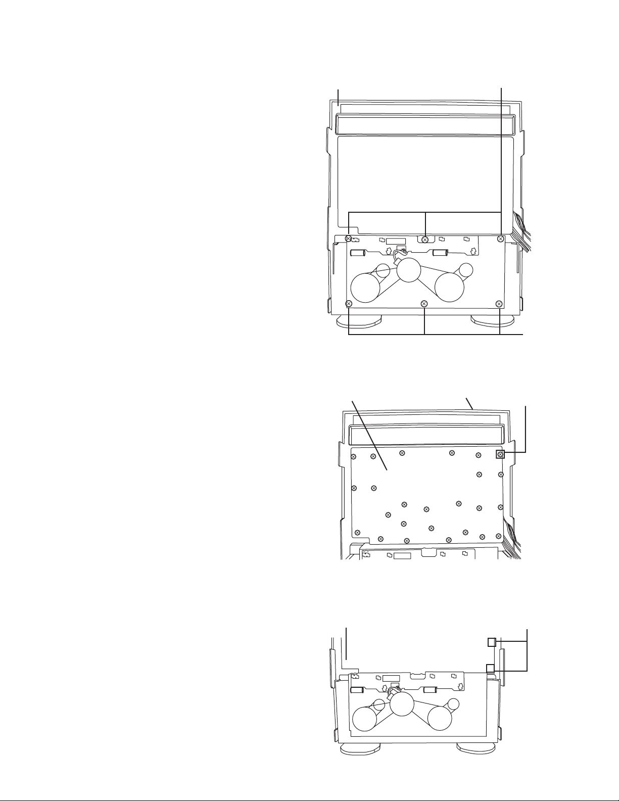
3.1.4 Removing the top cover right cabinet and left cabinet
(See Fig.4 and 5)
(1) Remove three screws C that retain the top cover from the
panel rear of the body.
(2) Remove six screws D that retain the left cabinet from the
body.
(3) Remove six screws c that retain the right cabinet from the
body.
right cabinet
top cover
left cabinet
C
C
Right Front panel assembly
C
Fig.5
C
D
Fig.4
Left Front panel assembly
C
D
1-6 (No.MB434)
Page 7
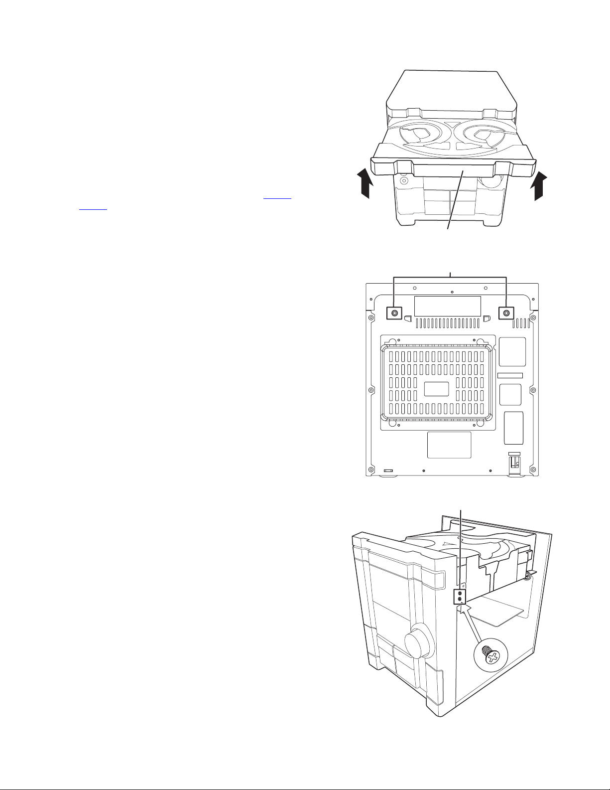
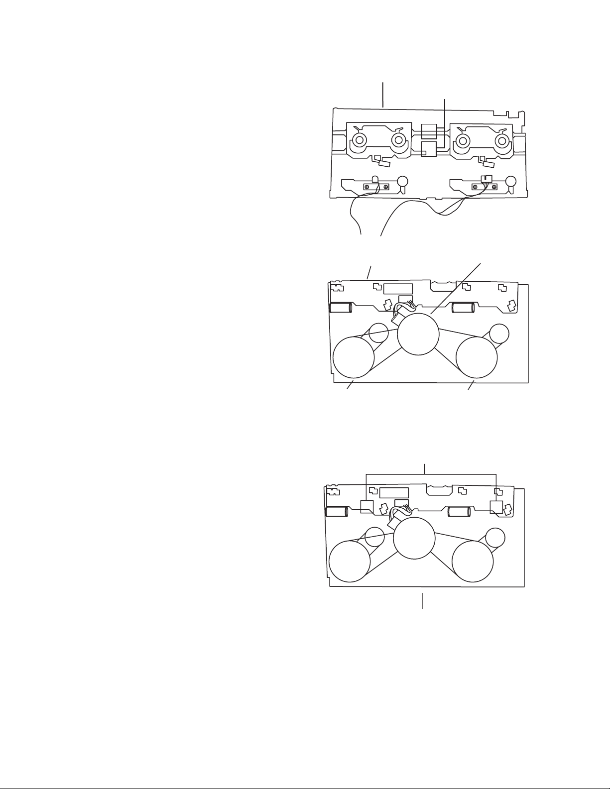
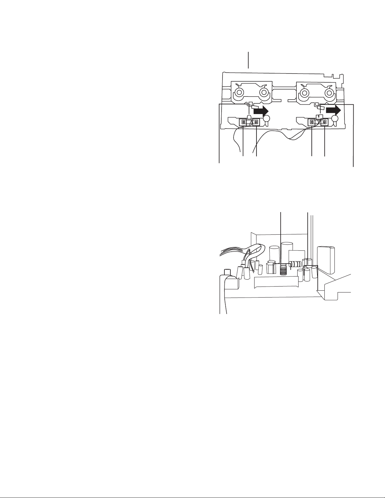
3.1.5 Removing the CD changer unit
(See Fig.6 to 8)
• Prior to performing the following procedures, remove the top
cover.
Caution:
Although the CD mechanism unit can be removed without removing the CD tray panel, it is still recommended to remove it
in order to prevent damage.
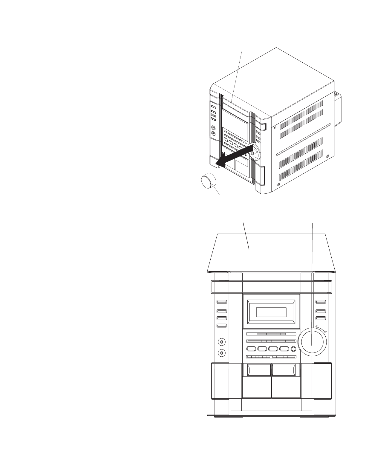
• From the front panel side of this set, push in the sections
marked with arrows and pull out the CD tray toward the front.
• Remove the CD tray panel by pushing both of its extremities
upward in the direction of the arrows.
• Push the CD tray deep into the set.
(1) Disconnect the cord wires from the CD board CN703
CN203.
(2) From the rear of the set, remove two screws E, and four
screws G on the front panel left and right side.
(3) Handle the CD changer unit rear, take out the unit.
and
UP
UP
CD tray panel
Fig.6
E
Fig.7
Fig.8
G
(No.MB434)1-7
Page 8
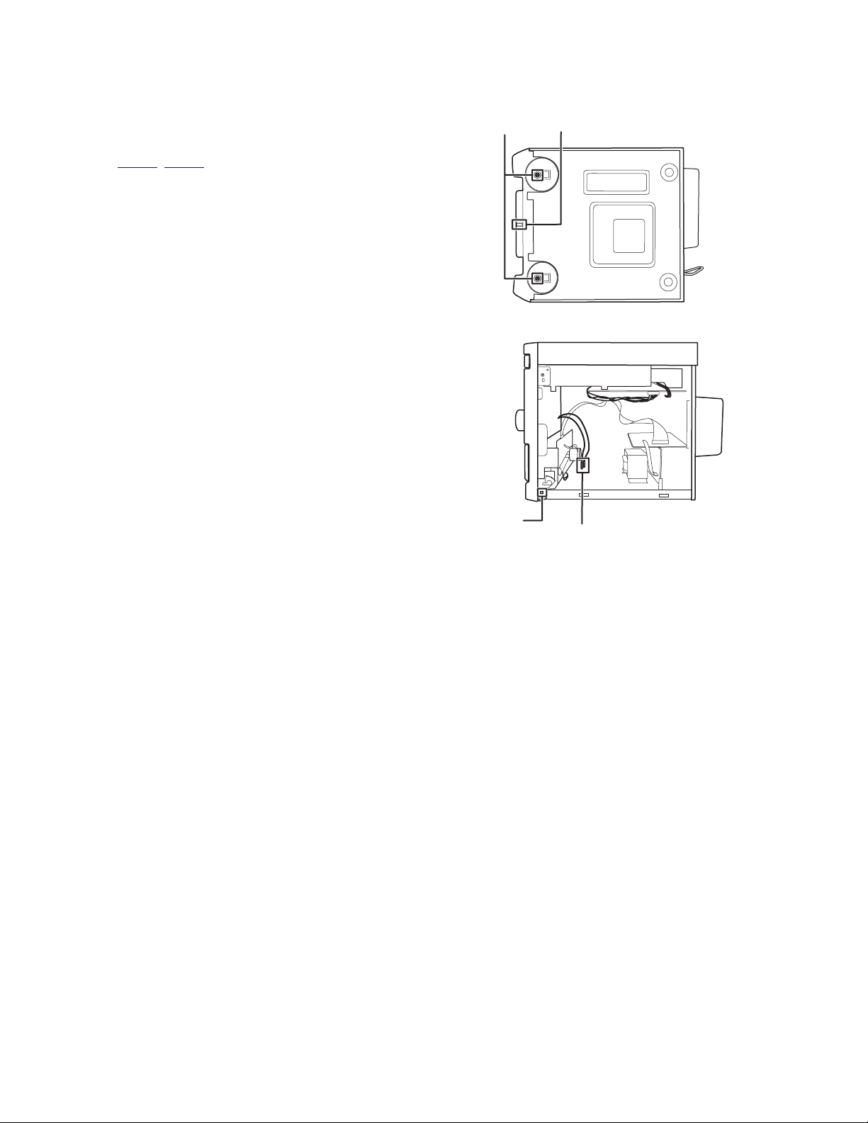
3.1.6 Removing the front panel assembly
(See Fig.9 to 10)
• Prior to performing the following procedures, remove the top
cover.
• Also remove the CD changer unit.
(1) Disconnect the parallel wire and the cord wire from the con-
nectors CN701
(2) Remove one screws H retaining the front panel assembly
onto the bottom of the body.
(3) Remove two screws I on the front cabinet and bottom cab-
inet and then remove then GND lug b that comes from the
power amp and supply board.
(4) Disengage the claws c on both sides of the front panel as-
sembly and then remove the assembly.
, CN101 on the power amp. board.
I
H
Fig.9
Claw
c
GND lug
GND lug
a
b
Fig.10
1-8 (No.MB434)
Page 9
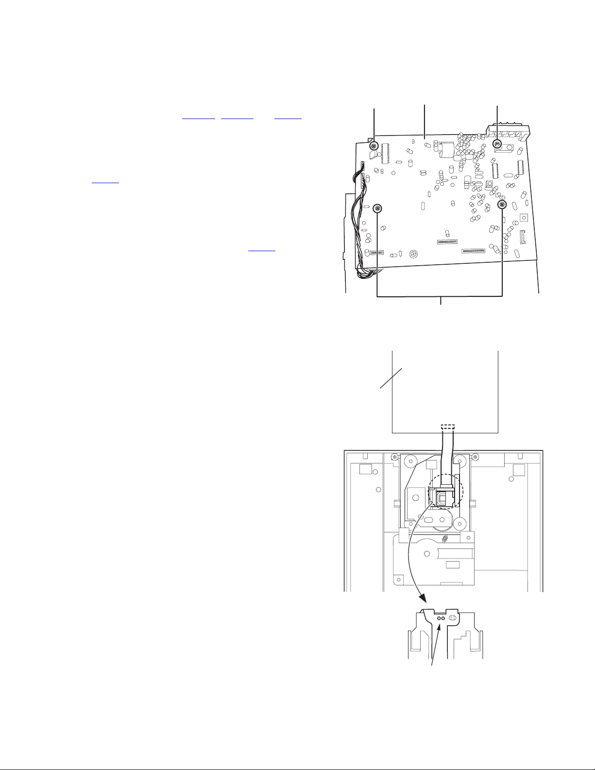
3.2 Disassembly of units and assembly inside this set
3.2.1 Removing the Main board
(See Fig.11 to 12)
• Prior to performing the following procedures, remove the top
cover.
• Also remove the CD changer unit.
(1) Disconnect the wires from CN603A
on the Main board, which is located on the back side of the
CD changer unit.
(2) The four screws J that retain the CD board should be re-
moved.
(3) Remove the CD board by pulling it toward the side where
the CN601
(4) Using solder, short the CD pickup to connect to short
round.
Caution:
After re-connecting the wires, be sure to remove the
shorting solder from the GND connection.
(5) Disconnect the card wire from the connector CN601
Main board and then remove the Main board.
is located.
, CN603B and CN604
on the
J
Main board
J
J
CD board
Fig.11
CN601
Short round
Fig.12
(No.MB434)1-9
Page 10
3.2.2 Removing the CD changer mechanism assembly
(See Fig.13 to 14)
• Prior to performing the following procedures, remove the top
cover.
• Also remove the CD changer unit.
(1) Turn the CD changer mechanism cover base and remove
the screws d connecting the unit to the CD changer mechanism assembly.
(2) Removing four screws e retaining the CD mechanism hold-
er assembly.
Caution:
When replacing the CD changer mechanism assembly, be
sure not to mistake the positions of the silver color and copper
color spring.
CD changer
unit
e
( Green color )
e
( Green color )
d
Fig.13
CD changer
mechanism
assemb
ly
Fig.14
e
( Red color )
e
( Red color )
1-10 (No.MB434)
Page 11
3.2.3 Removing the CD pickup
r
(See Fig.15)
• Prior to performing the following procedures, remove the top
cover.
• Also remove the CD changer unit.
• Also remove the CD changer mechanism.
(1) Widen the section f.
(2) While keeping the section f wide open, push the section g
in the direction of the arrow to remove the shaft, and then
remove the CD pickup.
CD pickup
f
3.2.4 Replacing the loading motor and rotor belt of the CD changer
(See Fig .16)
• Prior to performing the following procedures, remove the top
cover.
• Also open the CD changer tray.
(1) Remove the two screws L retaining the CD changer tray
loading motor.
(2) Remove the two screws M retaining the gear plate and take
it out, after remove the rotor belt from the pulley.
g
Shaft
Fig.15
M
L
3.2.5 Replacing the CD turn table and removing the motor
(See Fig. 17)
• Prior to performing the following procedures, remove the top
cover.
• Also remove the CD changer unit.
(1) Remove the one screw retaining the CD (Turn table).
(2) Remove the two screws retaining the stopper brackets on
both sides of the CD changer unit.
(3) Remove the stopper brackets from both sides of the CD
changer unit.
(4) Pull out the CD tray from the CD changer unit, all the way
and lift the tray to remove.
(5) Remove the gear and after push out the tray motor locker
and pull out the tray motor from the CD tray.
Fig.16
Turn table motor
Motor locker
Obligue gea
Fig.17
(No.MB434)1-11
Page 12
3.2.6 Removing the cassette deck mechanism
(See Fig.18)
• Prior to performing the following procedures, remove the top
cover.
• Also remove the CD changer unit.
• Also remove the front panel assembly.
(1) Remove six screws retaining the cassette deck mecha-
nism.
3.2.7 Removing the key open board & the key REC board
(See Fig.19)
• Prior to performing the following procedures, remove the top
cover.
• Also remove the CD changer unit.
• Also remove the front panel assembly.
(1) Remove 25 screws P that retains the key open board.
Front panel
Front board
assembly
Fig.18
Front panel
assembly
Z
Z
P
3.2.8 Removing the display board
(See Fig.20)
• Prior to performing the following procedures, remove the top
cover.
• Also remove the CD changer unit.
• Also remove the front panel assembly.
(1) Remove 25 screws Q that retain the front board from the
back of the front panel unit.
1-12 (No.MB434)
Display board
Fig.19
Q
Fig.20
Page 13
3.2.9 Removing the Switch board and sound mode and CD function switch board
(See Fig.19 to 22)
• Prior to performing the following procedures, remove the top
cover.
• Also remove the CD changer unit.
• Also remove the front panel assembly.
(1) Pull out the volume control knob from the front of the front
panel assembly.(Fig.21)
(2) Remove six screws Q retaining the front panel assembly.
(3) Remove the Control/FL board.
(4) Remove eleven screws R retaining the Switch (key 1)
board.(Fig.19)
(5) Remove two screws S retaining the sound mode and CD
function (key 2) switch board.(Fig.20)
Front panel assembly
Volume knob
Front panel
assembly
Fig.21
Volum
shaft
Fig.22
(No.MB434)1-13
Page 14
3.2.10 Removing the cassette deck main motor, and replacing the main belts
r
(See Fig.18, 23 and 24)
• Prior to performing the following procedures, remove the top
cover and both sides board.
• Also remove the CD changer unit.
• Also remove the front panel assembly.
(1) Remove six screws Z retaining the cassette deck mecha-
nism. (Fig.18)
(2) Remove the cassette deck mechanism.
(3) Remove two screws t retaining the main motor from the
front side of the cassette deck.
Caution:
After attaching the main motor, check the orientation of
the motor and the polarity of the wires.
(4) From the backside of the cassette deck, remove the main
motor and two main belts.
Caution:
The lengths of the cassette A(playback only) and cassette
B(record/play) main belts are different. When attaching the
main belts, use the longer belt for cassette A.
Cassette deck mechanism
Cassette deck mechanism
(Back side)
(Front side)
t
Fig.23
Cassette deck main moto
3.2.11 Removing the leaf switches of the cassette deck mechanism
(See Fig. 18 and 25)
• Prior to performing the following procedures, remove the top
cover and both sides board.
• Also remove the CD changer unit.
• Also remove the front panel assembly.
(1) Remove the six screws Z that retain the cassette deck
mechanism. (Fig.18)
(2) Remove the cassette deck mechanism.
(3) Turn the cassette deck mechanism upside down.
(4) Remove the solder from around the leaf switches.
(5) Pull out the leaf switches from the front side of the cassette
deck mechanism.
Main belt
(For B cassette)
Cassette deck mechanism
Main belt
(For A cassette)
Fig.24
Solder side of leaf switch
(Back side)
Fig.24
1-14 (No.MB434)
Page 15
3.2.12 Removing the cassette deck heads
(See Fig. 18 and 26)
• Prior to performing the following procedures, remove the top
cover and both sides board.
• Also remove the CD changer unit.
• Also remove the front panel assembly.
(1) Remove six screws Z that retain the cassette deck mecha-
nism. (Fig.18)
(2) Remove the cassette deck mechanism and place it so that
the front side faces up.
(3) Remove the solder from the bottom side of the head termi-
nal and disconnect the wire.
(4) Remove screws U that retains the head.
(5) Remove screws V that retains the head.
(6) Hold the head and slide it in the direction of the arrow to re-
move it.
Cassette dec k mechanism
(Front side)
3.2.13 Removing the 3-pin regulator and bridge diode
(See Q604, Q608, D614, D615 and Fig.27)
• Prior to performing the following procedures, remove the top
cover and both sides board.
(1) Remove two screws A that connect the heat sink.
(2) Remove two screws W that connect the heat sink.
(3) Remove the solder fixing the 3-pin terminal regulator Q604,
Q608.
(4) Remove the solder fixing the 4-pin bridge diode (D614,
D615).
PB Head
V
U
Fig.26
W
Fig.27
VU
REC/PB Head
A
(No.MB434)1-15
Page 16

3.2.14 Removing the power amp and Supply board and the Power trans board
(See Fig. 2, 28 to 30)
• Prior to performing the following procedures, remove the top
cover and CD changer unit.
(1) Remove four screws B from the rear panel. (Fig.3)
(2) Pull the heat sink cover outward.
(3) Remove four screws AA from the rear panel between the
heat sink holder.
(4) Remove two screws YY that retains the rear panel, and
then remove the rear panel.
(5) Disconnect the parallel wires from the connectors FW951
on the Power trans board.
(6) Remove screws Z that retain the power amp and Supply
board and then remove the assembly.
(7) Remove the clamp of AC power cord from the chassis.
(8) Remove four screws that retain the Power trans board and
then remove the assembly.
Fuse (F901)
1.6AL 250V
Fig.28
Rear panel
YY
Clamp
Fig.29
Power amp and supply board
Z
Fig.30
Chassis
1-16 (No.MB434)
Page 17

SECTION 4
ADJUSTMENT
This service manual does not describe ADJUSTMENT.
SECTION 5
TROUBLESHOOTING
This service manual does not describe TROUBLESHOOTING.
(No.MB434)1-17
Page 18

Victor Company of Japan, Limited
AV & MULTIMEDIA COMPANY AUDIO/VIDEO SYSTEMS CATEGORY 10-1,1chome,Ohwatari-machi,Maebashi-city,371-8543,Japan
(No.MB434)
Printed in Japan
VPT
Page 19

SCHEMATIC DIAGRAMS
COMPACT COMPONENT SYSTEM
MX-KC2
CD-ROM No.SML200510
Area suffix
UW ----------- Brazil,Mexico,Peru
UY ------------------------ Argentina
Lead free solder used in the board (material : Sn-Ag-Cu, melting point : 219 Centigrade)
Contents
Block diagram
Standard schematic diagrams
Printed circuit boards
COPYRIGHT 2005 Victor Company of Japan, Limited.
CA-MXKC2 SP-MXKC2SP-MXKC2
2-1
2-2
2-8 to 13
No.MB434SCH
2005/10
Page 20

In regard with component parts appearing on the silk-screen printed side (parts side) of the PWB diagrams, the
parts that are printed over with black such as the resistor ( ), diode ( ) and ICP ( ) or identified by the " "
mark nearby are critical for safety.
Page 21

Block diagram
Pickup ass'y
Loader ass'y
VREF
SVCC
A B C D E F
GND
T+ TF+ F-
SP+/- SL+/IN-SW
MO+/- RL+/-
5V
SENSE CATHODE
SW1-2
LD
VR
PD
Motor
driver
SPDRV
TRVDRV
FG
FODRV
DRVMUTE
SPMUTE
VHALF
16.93MHz
ASP
Main board
16M SDRAM
DB0-7
ADD0-10
BA0 RAS CAS DRW
LDQM CKE
XSCLK UDQM
CD / MP3
DECODER
3.3V
1.8V
M8V
D5V
3.3V
regulator
1.8V
regulator
FAOUTL
FAOUTR
VFD DISPLAY
VFD
driver
TUNER MODULE
FM / AM
ST LED
9V
TUNER-L
GND
TUNER-R
CE1
DATA IN
CLK1
DATA OUT
D-GND
NG
NG
AUX
AC IN
Voltage supply
Main
transf.
Primary fuse
Sub-transf.
<=1.5W
Rellay
DISPLAY O/P
SYSTEM MICON
TU CONT.
Main board
CD L/R
TU L/R
AUX L/R
FUNC IC
VOLUME
FUNCTION SW
SURROUND
VOLTAGE SUPPLY
MAIN CH
6 OHM6 OHM
POWER AMP
Main board
HEADPHONE
VOLTAGE SUPPLY
HP OUT
2-1
Page 22

Standard schematic diagrams
Primary section
2-2
Parts are safety assurance parts.
When replacing those parts make
sure to use the specified one.
Page 23

Power amp. section
Parts are safety assurance parts.
When replacing those parts make
sure to use the specified one.
2-3
Page 24

Micon section
2-4
Page 25

Source selector section
2-5
Page 26

CD section
2-6
Page 27

Front section
2-7
Page 28

Printed circuit boards
Main board
Lead free solder used in the board (material : Sn-Ag-Cu, melting point : 219 Centigrade)
forward side
2-8
Page 29

Main board
Lead free solder used in the board (material : Sn-Ag-Cu, melting point : 219 Centigrade)
reverse side
2-9
Page 30

Amp board
Lead free solder used in the board (material : Sn-Ag-Cu, melting point : 219 Centigrade)
forward side reverse side
2-10
Page 31

Front board
forward side
Lead free solder used in the board (material : Sn-Ag-Cu, melting point : 219 Centigrade)
2-11
Page 32

Front board
reverse side
Lead free solder used in the board (material : Sn-Ag-Cu, melting point : 219 Centigrade)
2-12
Page 33

Trans board
Lead free solder used in the board (material : Sn-Ag-Cu, melting point : 219 Centigrade)
2-13
Page 34

Victor Company of Japan, Limited
AV & MULTIMEDIA COMPANY AUDIO/VIDEO SYSTEMS CATEGORY 10-1,1chome,Ohwatari-machi,Maebashi-city,371-8543,Japan
(No.MB434SCH)
Printed in Japan
VPT
Page 35

PARTS LIST
[ MX-KC2 ]
* All printed circuit boards and its assemblies are not available as service parts.
Area suffix
UW ---------- Brazil,Mexico,Peru
UY ----------------------- Argentina
MB434
- Contents -
Exploded view of general assembly and parts list (Block No.M1)
CD changer mechanism assembly and partslist (Block No.MA)
Electrical parts list (Block No.01~05)
Packing materials and accessories parts list (Block No.M3)
3- 2
3- 5
3- 7
3-14
3-1
Page 36

Exploded view of general assembly and parts list
8
4
Block No.
26
Main board
46
30
47
28
M
M
1
M
47
25
24
50
40
39
31
29
35
37
38
1
2
36
5
3
4
33
34
46
6
46
45
47
44
32
41
12
46
46
14
13
Front board
10
46
9
8
53
F902
43
15
50
4
48
50
52
F901
Pow
3-2
49
7
11
Page 37

50
25
47
24
23
21
47
46
46
46
47
47
22
54
49
49
20
49
43
oard
5
50
48
50
52
F901
46
48
48
Amp board
Power board
46
48
47
18
19
47
47
16
47
47
47
The parts without symbol number are not service.
3-3
Page 38

General Assembly
Symbol No. Part No. Part Name Description Local
1 BI1081090101V1 CASS LENS L
2 BI1081100101V1 CASS LENS R
3 BI1081160101V1 CASSETTE BOX R
4 BI202929010101 C DOOR SPRING R
5 BI1081060101V1 VOL KNOB
6 BI1081040102X1 FRONT CABINET 94HB
7 BI301779010101 CUSHION BACK FOAM(x2)
8 BI300924010101 DAMPER
9 BI1077330101U1 VOL RING ABS 700
10 BI2029250101W1 BOTTOM CABINET
11 BI3021970101V1 RUBBER FOOT (x2)
12 BI250111002000 CASSETTE MECH CWN42FF06
13 BI1081120101V1 SOUND MODE KEY
14 BI1081560101V1 LED HDLR
15 BI211011128001 POWER TRANS EI66X50 DB-EI66-3700A PT901
16 BI1081180101V1 RIGHT CABINET
18 BI202560010101 HEAT SINK HLDR R SBCC T=0.80mm
19 BI2029260301W1 BACK PANEL UW
19 BI2029260401W1 BACK PANEL UY
20 BI107843010101 HT SINK COVER KA6 PA-757
21 BIZ25094901VV TUNER PACK
22 BI1081140101V1 TOP CABINET
23 BI202923010201 HEAT SINK AL
24 BI202553010101 HEAT SINK HLDR L SBCC T=0.80mm
25 BI202555010101 HEAT SINK
26 BI251030093100 3CD MECHANISM CMS-FR3BN
28 BI1081170101V1 LEFT CABINET
29 BI2702221V VFD DISPLAY VFD1 BJ967GNK
30 BI1081110101V1 CD PLAY KEY
31 BI1081130101V1 LENS POWER
32 BI1081080101V1 KEY FUNC
33 BI1077330101U1 VOL RING ABS 700
34 BI300924010101 DAMPER
35 BI2029680101W1 HOLDER PLATE
36 BI109835010101 BADGE 700194HB
37 BI1081050101V1 CD DOOR
38 BI1081070101V1 WIN DISP
39 BI202928010101 C DOOR SPRING L
40 BI1081150101V1 CASSETTE BOX L
41 BI2029270101W1 SENSOR BRACKET
43 BI1081190101V1 VFD BRACKET
44 BI202772010101 CASSETTE SPRING SUS WPB 0.40
45 BI202773010101 C LOCKER SPRING
46 BIRT000611B3 SCREW 3 X L8 B-TYPE(x26)
47 BIRT000617B3 SCREW 3 X L10 B-TYPE(x19)
48 BIRM000603S3 SCREW 3 X L6 S-TYPE(x7)
49 BIRM000604S3 SCREW 3X L8 S-TYPE(x6)
50 BIBT000418 SCREW 2.6 XL8(x25)
52 BI402891 FUSE T1.6AL 250V F901
53 BI402821 FUSE 1A 250V F902
54 BI1401761V POWER CORD UW
54 BI1401791X POWER CORD UY
Block No. [M][1][M][M]
3-4
Page 39

CD changer mechanism assembly and parts list
Block No.
M
M
M
A
CMS-FR3BN
7
6
8
9
10
12
11
2
13
1
23
24
25
28
26
27
33
35
29
34
14
15
19
32
22
16
21
37
38B
17
18
20
36
37
38A
3
4
5
37
38A
37
38B
39
The parts without symbol number are not service.
3-5
Page 40

CD changer mechanism
Symbol No. Part No. Part Name Description Local
1 BIAJ7200601J BASE-MAIN 1X1
2 BIAJ6100601P BRKT-CHUCK
3 BI3302000158 MAGNET-FERRITE
4 BIAJ7200601L TABLE-CHUCK 1X4
5 BIAJ6300601A SHEET-CHUCK (x3)
6 BIAJ7300601B BELT-LOAD
7 BIAJ6600601N GEAR-SYNCRO 1X2
8 BIAJ6600601L GEAR-CONVERT 1X4
9 BIAJ6600601M GEAR-TRAY 1X4
10 BIAJ6600601R GEAR-CAM 1X2
11 BIAJ6600601K GEAR-LOAD 1X4
12 BIAJ6600601J GEAR-PULLEY 1X4
13 BIAJ7200601N SLIDER-CAM 1X4
14 BI3405000101 SWITCH-MICRO (x2)
15 BI3711003379 CONNECTOR-HEADE
16 BIAJ4100601K PCB-SW
17 BIAJ6100601K PULLEY-MOTOR 1X4
18 BIAJ3100601F MOTOR-DC
19 BI3710001248 CONNECTOR-SOCE
20 BI3711003692 CONNECTOR-HEADE
21 BI3708001163 CONNECTOR-FPC
22 BIAJ4100601L PCB-MECHA
23 BIAJ7200601P TRAY-ROULETTE 1X2
24 BIAJ7200601Q TRAY-DISC 1X2
25 BIAJ6600601Q GEAR-ROULETTE 1X4
26 BIAJ6600601P GEAR-WORM 1X2
27 BIAJ3100601K MOTOR-LOADING
28 BIAJ6300601B SHEET-MOTOR
29 BIAJ3900601A WIRE-ROULETTE
32 BIAJ3900601B WIRE-TRAY
33 BI3711000003 CONNECTOR-HEADE
34 BIAJ4100601J PCB-SENSOR
35 BIAJ3200601A SENSOR-ROULETTE
36 BIAJ9050605F CMS-B31NG6U
37 BIAJ6000601F SCREW (x4)
38A BIAJ7300601F RUBBER-B31Y (x2)
38B BIAJ7300601D RUBBER-B31 (x2)
39 BIAJ7200602F LEVER-LIFTER 1X2
Block No. [M][A][M][M]
3-6
Page 41

Electrical parts list
Main board
Block No. [0][1]
Symbol No.
IC301 S3C825A IC BI118371
IC302 BU4051BCF IC BI116691
IC401 BD3881FV IC BI112721
IC701 S1L9226 IC BI116431
IC702 BA5927FM IC BI118221
IC801 BH18FB1WG IC BI118171
IC802 NJM7808FA IC BI110061
IC803 K4S161622H-UC60 IC BI117401V
IC804 S5L9279 IC BI116401
Q302 2SC3052 TRANSISTOR BI2SC3052FA013H
Q303 DTC114YK DIGI TRANSISTOR BI2DTC114YKA018
Q304 2SC1815 TRANSISTOR BI2SC1815GRP000
Q401 2SJ460 TRANSISTOR BI2SJ460P0001
Q402 2SJ460 TRANSISTOR BI2SJ460P0001
Q403 2SK2541 TRANSISTOR BI2SK2541P0001
Q404 2SK2541 TRANSISTOR BI2SK2541P0001
Q405 2SJ460 TRANSISTOR BI2SJ460P0001
Q406 2SJ460 TRANSISTOR BI2SJ460P0001
Q407 2SK2541 TRANSISTOR BI2SK2541P0001
Q408 2SK2541 TRANSISTOR BI2SK2541P0001
Q409 2SK2541 TRANSISTOR BI2SK2541P0001
Q410 SRA2202S TRANSISTOR BI2SRA2202SA00
Q411 2SK2158 F.E.T BI2SK2158A015V1
Q412 2SK2158 F.E.T BI2SK2158A015V1
Q413 2SC3052 TRANSISTOR BI2SC3052FA013H
Q414 2SC3052 TRANSISTOR BI2SC3052FA013H
Q415 KTA1273 TRANSISTOR BI2KTA1273P0008
Q416 2SC3052 TRANSISTOR BI2SC3052FA013H
Q417 KTA1273 TRANSISTOR BI2KTA1273P0008
Q418 DTC114TK DIGI TRANSISTOR BI2DTC114TKA011
Q419 KTA1273 TRANSISTOR BI2KTA1273P0008
Q420 2SC3052 TRANSISTOR BI2SC3052FA013H
Q421 2SC3052 TRANSISTOR BI2SC3052FA013H
Q422 2SC3052 TRANSISTOR BI2SC3052FA013H
Q423 KTA1267GR TRANSISTOR BI2KTA1267GP00
Q433 2SC3052 TRANSISTOR BI2SC3052FA013H
Q434 2SC5343 TRANSISTOR BI2SC5343GP0000
Q435 2SC5343 TRANSISTOR BI2SC5343GP0000
Q436 2SC5343 TRANSISTOR BI2SC5343GP0000
Q437 2SC3052 TRANSISTOR BI2SC3052FA013H
Q438 DTC114TK DIGI TRANSISTOR BI2DTC114TKA011
Q501 2SC3052 TRANSISTOR BI2SC3052FA013H
Q504 KTA1267GR TRANSISTOR BI2KTA1267GP00
Q505 DTC114TK DIGI TRANSISTOR BI2DTC114TKA011
Q506 KTA1267GR TRANSISTOR BI2KTA1267GP00
Q507 DTC114TK DIGI TRANSISTOR BI2DTC114TKA011
Q508 2SC1815 TRANSISTOR BI2SC1815GRP000
Q509 DTC114TK DIGI TRANSISTOR BI2DTC114TKA011
Q701 KTA1266GR TRANSISTOR BI2KTA1266GP00
Q703 KTC3205 TRANSISTOR BI2KTC3205P0008
Q704 2SC1815 TRANSISTOR BI2SC1815GRP000
D301 1SS133 FR DIODE BI31SS133M000V7
D302 1SS133 FR DIODE BI31SS133M000V7
D303 1SS133 FR DIODE BI31SS133M000V7
D304 1SS133 FR DIODE BI31SS133M000V7
D305 1SS133 FR DIODE BI31SS133M000V7
D306 UZ4.7BSA Z DIODE BI3UZ4.7BSAM000
D307 1SS133 FR DIODE BI31SS133M000V7
D308 1SS133 FR DIODE BI31SS133M000V7
D309 1SS133 FR DIODE BI31SS133M000V7
D401 MC2836 DIODE BI3MC2836A002H
D402 UZ4.7BSA Z DIODE BI3UZ4.7BSAM000
D403 1SS133 FR DIODE BI31SS133M000V7
D404 1SS133 FR DIODE BI31SS133M000V7
D405 UZ4.7BSA Z DIODE BI3UZ4.7BSAM000
D501 1SS133 FR DIODE BI31SS133M000V7
D502 1SS133 FR DIODE BI31SS133M000V7
D503 1SS133 FR DIODE BI31SS133M000V7
D504 1SS133 FR DIODE BI31SS133M000V7
D505 1SS133 FR DIODE BI31SS133M000V7
Part No. Part Name Description Local
Symbol No.
D508 1SS133 FR DIODE BI31SS133M000V7
D509 1SS133 FR DIODE BI31SS133M000V7
D510 1N4001 DIODE BI31N4001M0006
D511 1SS133 FR DIODE BI31SS133M000V7
D516 UZ11BSC Z DIODE BI3UZ11BSCM0000
D517 UZ9.1BSC Z DIODE BI3UZ91BSCM000V
D710 UZ3.6BSB Z DIODE BI3UZ3.6BSBM000
D711 UZ3.6BSB Z DIODE BI3UZ3.6BSBM000
D712 1SS133 FR DIODE BI31SS133M000V7
C301 BICC104500KA04 C CAPACITOR 0.1uF 50V
C302 BICC104500KA04 C CAPACITOR 0.1uF 50V
C303 BICC223500KA04 C CAPACITOR 0.022uF 50V
C304 BICE107100MP01 E CAPACITOR 100uF 10V
C305 BICE108100MP01 E CAPACITOR 1000uF 10V
C306 BICE476250MP01 E CAPACITOR 47uF 25V
C307 BICC104500KA04 C CAPACITOR 0.1uF 50V
C308 BICC104500KA04 C CAPACITOR 0.1uF 50V
C311 BICC270500JA04 C CAPACITOR 27pF 50V
C312 BICC240500JA04 C CAPACITOR 24pF
C313 BICC330500JA04 C CAPACITOR 33pF 50V
C314 BICC102500KA04 C CAPACITOR 1000pF 50V
C315 BICC220500JA04 C CAPACITOR 22pF 50V
C316 BICC220500JA04 C CAPACITOR 22pF 50V
C317 BICC105160ZA02 C CAPACITOR 1uF 16V
C318 BICE105500MP01 E CAPACITOR 1uF 50V
C319 BICH104500KM01 C CAPACITOR 0.1uF 50V
C321 BICC101500JA04 C CAPACITOR 100pF 50V
C322 BICC101500JA04 C CAPACITOR 100pF 50V
C323 BICC101500JA04 C CAPACITOR 100pF 50V
C324 BICC101500JA04 C CAPACITOR 100pF 50V
C325 BICC101500JA04 C CAPACITOR 100pF 50V
C326 BICC101500JA04 C CAPACITOR 100pF 50V
C327 BICC101500JA04 C CAPACITOR 100pF 50V
C401 BICC122500KA04 C CAPACITOR 1200pF 50V
C402 BICC122500KA04 C CAPACITOR 1200pF 50V
C403 BICC470500JA04 C CAPACITOR 47pF 50V
C404 BICC470500JA04 C CAPACITOR 47pF 50V
C405 BICE226100MP01 E CAPACITOR 22uF 10V
C406 BICE226100MP01 E CAPACITOR 22uF 10V
C407 BICE225500MP01 E CAPACITOR 2.2uF 50V
C408 BICC471500KA04 C CAPACITOR 470pF 50V
C409 BICC103500KA04 C CAPACITOR 0.01uF 50V
C410 BICC103500KA04 C CAPACITOR 0.01uF 50V
C411 BICC181500JA04 C CAPACITOR 180pF 50V
C412 BICC181500JA04 C CAPACITOR 180pF 50V
C413 BICE107100MP01 E CAPACITOR 100uF 10V
C414 BICC561500KA04 C CAPACITOR 560pF 50V
C415 BICC561500KA04 C CAPACITOR 560pF 50V
C416 BICC332500KA04 C CAPACITOR 3300pF 50V
C417 BICE227160MP01 E CAPACITOR 220uF 16V
C418 BICE225500MP01 E CAPACITOR 2.2uF 50V
C419 BICC332500KA04 C CAPACITOR 3300pF 50V
C420 BICE224500MP01 E CAPACITOR 0.22uF 50V
C421 BICC101500JA04 C CAPACITOR 100pF 50V
C422 BICE224500MP01 E CAPACITOR 0.22uF 50V
C423 BICC104500KA04 C CAPACITOR 0.1uF 50V
C424 BICC104500KA04 C CAPACITOR 0.1uF 50V
C425 BICE224500MP01 E CAPACITOR 0.22uF 50V
C426 BICC122500KA04 C CAPACITOR 1200pF 50V
C427 BICC181500JA04 C CAPACITOR 180pF 50V
C428 BICE227160MP01 E CAPACITOR 220uF 16V
C429 BICC122500KA04 C CAPACITOR 1200pF 50V
C430 BICC102500KA04 C CAPACITOR 1000pF 50V
C432 BICC103500KA04 C CAPACITOR 0.01uF 50V
C433 BICC222500KA04 C CAPACITOR 2200pF 50V
C434 BICC181500JA04 C CAPACITOR 180pF 50V
C435 BICC103500KA04 C CAPACITOR 0.01uF 50V
C436 BICC103500KA04 C CAPACITOR 0.01uF 50V
C437 BICC682500KA04 C CAPACITOR 6800pF 50V
C438 BICC104500KA04 C CAPACITOR 0.1uF 50V
C439 BICC103500KA04 C CAPACITOR 0.01uF 50V
C440 BICE227160MP01 E CAPACITOR 220uF 16V
C441 BICC272500KA04 C CAPACITOR 2700pF
C443 BICC473500KA04 C CAPACITOR 0.047uF 50V
C444 BICC222500KA04 C CAPACITOR 2200pF 50V
Part No. Part Name Description Local
3-7
Page 42

Symbol No.
Part No. Part Name Description Local
Symbol No.
Part No. Part Name Description Local
C445 BICE224500MP01 E CAPACITOR 0.22uF 50V
C446 BICC103500KA04 C CAPACITOR 0.01uF 50V
C447 BICE107160MP01 E CAPACITOR 100uF 16V
C448 BICC682500KA04 C CAPACITOR 6800pF 50V
C449 BICC103500KA04 C CAPACITOR 0.01uF 50V
C450 BICE475500MP01 E CAPACITOR 4.7uF 50V
C451 BICE107160MP01 E CAPACITOR 100uF 16V
C453 BICC102500KA04 C CAPACITOR 1000pF 50V
C454 BICC102500KA04 C CAPACITOR 1000pF 50V
C458 BICE476160MP01 E CAPACITOR 47uF 16V
C459 BICE225500MP01 E CAPACITOR 2.2uF 50V
C460 BICE225500MP01 E CAPACITOR 2.2uF 50V
C461 BICC332500KA04 C CAPACITOR 3300pF 50V
C462 BICC332500KA04 C CAPACITOR 3300pF 50V
C463 BICC104500KA04 C CAPACITOR 0.1uF 50V
C501 BICC123500KA04 C CAPACITOR 0.012uF
C502 BICC473500KA04 C CAPACITOR 0.047uF 50V
C503 BICM682101KP01 M CAPACITOR 6800pF 100V
C518 BICC272500KA04 C CAPACITOR 2700pF
C520 BICC272500KA04 C CAPACITOR 2700pF
C521 BICC561500KA04 C CAPACITOR 560pF 50V
C524 BICE105500MP01 E CAPACITOR 1uF 50V
C525 BICE475500MP01 E CAPACITOR 4.7uF 50V
C526 BICE105500MP01 E CAPACITOR 1uF 50V
C527 BICE475500MP01 E CAPACITOR 4.7uF 50V
C528 BICE476160MP01 E CAPACITOR 47uF 16V
C535 BICE476160MP01 E CAPACITOR 47uF 16V
C536 BICC102500KA04 C CAPACITOR 1000pF 50V
C539 BICC102500KA04 C CAPACITOR 1000pF 50V
C540 BICC101500JA04 C CAPACITOR 100pF 50V
C541 BICC101500JA04 C CAPACITOR 100pF 50V
C542 BICE105500MP01 E CAPACITOR 1uF 50V
C543 BICE105500MP01 E CAPACITOR 1uF 50V
C544 BICE475500MP01 E CAPACITOR 4.7uF 50V
C545 BICE475500MP01 E CAPACITOR 4.7uF 50V
C546 BICE475500MP01 E CAPACITOR 4.7uF 50V
C547 BICE475500MP01 E CAPACITOR 4.7uF 50V
C557 BICE107100MP01 E CAPACITOR 100uF 10V
C558 BICC103500KA04 C CAPACITOR 0.01uF 50V
C561 BICC104500KA04 C CAPACITOR 0.1uF 50V
C701 BICC104500KA04 C CAPACITOR 0.1uF 50V
C702 BICC104500KA04 C CAPACITOR 0.1uF 50V
C703 BICC102500KA04 C CAPACITOR 1000pF 50V
C704 BICE476160MP01 E CAPACITOR 47uF 16V
C705 BICC102500KA04 C CAPACITOR 1000pF 50V
C706 BICC102500KA04 C CAPACITOR 1000pF 50V
C707 BICC103500KA04 C CAPACITOR 0.01uF 50V
C708 BICC473500KA04 C CAPACITOR 0.047uF 50V
C709 BICE107100MP01 E CAPACITOR 100uF 10V
C710 BICE107100MP01 E CAPACITOR 100uF 10V
C711 BICC020500CA04 C CAPACITOR 2pF
C712 BICC100500DA04 C CAPACITOR 10pF 50V
C713 BICC682500KA04 C CAPACITOR 6800pF 50V
C714 BICC103500KA04 C CAPACITOR 0.01uF 50V
C715 BICE475500MP01 E CAPACITOR 4.7uF 50V
C716 BICC104500KA04 C CAPACITOR 0.1uF 50V
C717 BICC104500KA04 C CAPACITOR 0.1uF 50V
C718 BICC102500KA04 C CAPACITOR 1000pF 50V
C719 BICC104500KA04 C CAPACITOR 0.1uF 50V
C720 BICC333250KA04 C CAPACITOR 0.033uF 25V
C721 BICC474100KA04 C CAPACITOR 0.47uF 10V
C722 BICC332500KA04 C CAPACITOR 3300pF 50V
C723 BICC474100KA04 C CAPACITOR 0.47uF 10V
C724 BICC103500KA04 C CAPACITOR 0.01uF 50V
C725 BICC683160KA04 C CAPACITOR 0.068uF 16V
C726 BICE106160MP01 E CAPACITOR 10uF 16V
C727 BICC683160KA04 C CAPACITOR 0.068uF 16V
C728 BICC331500KA04 C CAPACITOR 330pF 50V
C729 BICC102500KA04 C CAPACITOR 1000pF 50V
C730 BICC222500KA04 C CAPACITOR 2200pF 50V
C731 BICC333250KA04 C CAPACITOR 0.033uF 25V
C732 BICC104500KA04 C CAPACITOR 0.1uF 50V
C733 BICC104500KA04 C CAPACITOR 0.1uF 50V
C759 BICC104500KA04 C CAPACITOR 0.1uF 50V
C763 BICE107100MP01 E CAPACITOR 100uF 10V
C764 BICC104500KA04 C CAPACITOR 0.1uF 50V
C765 BICE477100MP01 E CAPACITOR 470uF 10V
C766 BICC104500KA04 C CAPACITOR 0.1uF 50V
C767 BICE107100MP01 E CAPACITOR 100uF 10V
C768 BICC102500KA04 C CAPACITOR 1000pF 50V
C769 BICE476250MP01 E CAPACITOR 47uF 25V
C770 BICC391500JA04 C CAPACITOR 390pF 50V
C771 BICC391500JA04 C CAPACITOR 390pF 50V
C772 BICC391500JA04 C CAPACITOR 390pF 50V
C773 BICC391500JA04 C CAPACITOR 390pF 50V
C774 BICC102500KA04 C CAPACITOR 1000pF 50V
C801 BICH104500KM01 C CAPACITOR 0.1uF 50V
C802 BICH104500KM01 C CAPACITOR 0.1uF 50V
C803 BICE107100MP01 E CAPACITOR 100uF 10V
C804 BICC104500KA04 C CAPACITOR 0.1uF 50V
C805 BICC270500JA04 C CAPACITOR 27pF 50V
C806 BICC270500JA04 C CAPACITOR 27pF 50V
C807 BICC104500KA04 C CAPACITOR 0.1uF 50V
C808 BICE107100MP01 E CAPACITOR 100uF 10V
C809 BICC104500KA04 C CAPACITOR 0.1uF 50V
C810 BICC122500KA04 C CAPACITOR 1200pF 50V
C811 BICC122500KA04 C CAPACITOR 1200pF 50V
C812 BICC122500KA04 C CAPACITOR 1200pF 50V
C813 BICC104500KA04 C CAPACITOR 0.1uF 50V
C814 BICE107100MP01 E CAPACITOR 100uF 10V
C815 BICE107100MP01 E CAPACITOR 100uF 10V
C816 BICE475500MP01 E CAPACITOR 4.7uF 50V
C817 BICE475500MP01 E CAPACITOR 4.7uF 50V
C818 BICC102500KA04 C CAPACITOR 1000pF 50V
C819 BICC102500KA04 C CAPACITOR 1000pF 50V
C820 BICC104500KA04 C CAPACITOR 0.1uF 50V
C821 BICC104500KA04 C CAPACITOR 0.1uF 50V
C822 BICC104500KA04 C CAPACITOR 0.1uF 50V
C823 BICC104500KA04 C CAPACITOR 0.1uF 50V
C824 BICC104500KA04 C CAPACITOR 0.1uF 50V
C825 BICC104500KA04 C CAPACITOR 0.1uF 50V
C826 BICC104500KA04 C CAPACITOR 0.1uF 50V
C827 BICC104500KA04 C CAPACITOR 0.1uF 50V
C828 BICC104500KA04 C CAPACITOR 0.1uF 50V
C829 BICC104500KA04 C CAPACITOR 0.1uF 50V
C830 BICC104500KA04 C CAPACITOR 0.1uF 50V
C831 BICC104500KA04 C CAPACITOR 0.1uF 50V
C832 BICC100500DA04 C CAPACITOR 10pF 50V
C833 BICC330500JA04 C CAPACITOR 33pF 50V
C834 BICH104500KM01 C CAPACITOR 0.1uF 50V
C835 BICH104500KM01 C CAPACITOR 0.1uF 50V
C850 BICC104500KA04 C CAPACITOR 0.1uF 50V
Ω
R301 BIRC4710105A00 C RESISTOR 470
R302 BIRC1010105A00 C RESISTOR 100
R303 BIRC1010085M00 C RESISTOR 100
R304 BIRC1010105A00 C RESISTOR 100
R305 BIRC1010105A00 C RESISTOR 100
R306 BIRC1010105A00 C RESISTOR 100
R307 BIRC1010105A00 C RESISTOR 100
R308 BIRC1010105A00 C RESISTOR 100
R309 BIRC1010105A00 C RESISTOR 100
R310 BIRC1010105A00 C RESISTOR 100
R311 BIRC1010105A00 C RESISTOR 100
R312 BIRC1010105A00 C RESISTOR 100
R313 BIRC1010105A00 C RESISTOR 100
R314 BIRC1020105A00 C RESISTOR 1K
R315 BIRC2210105A00 C RESISTOR 220
R316 BIRC2210105A00 C RESISTOR 220
R317 BIRC1010085N00 C RESISTOR 100
R318 BIRC1010105A00 C RESISTOR 100
R319 BIRC1010105A00 C RESISTOR 100
R320 BIRC1010105A00 C RESISTOR 100
R321 BIRC1010085M00 C RESISTOR 100
R322 BIRC1010105A00 C RESISTOR 100
R323 BIRC1010105A00 C RESISTOR 100
R324 BIRC1010085M00 C RESISTOR 100
R326 BIRC0000105A00 C RESISTOR 0
R328 BIRC1010085M00 C RESISTOR 100
R329 BIRC2220085M00 C RESISTOR 2.2K
R330 BIRC2220105A00 C RESISTOR 2.2K
R331 BIRC2220105A00 C RESISTOR 2.2K
R332 BIRC2220105A00 C RESISTOR 2.2K
R333 BIRC1820105A00 C RESISTOR 1.8K
R334 BIRC2230105A00 C RESISTOR 22K
R335 BIRC2230105A00 C RESISTOR 22K
Ω
Ω
Ω
Ω
Ω
Ω
Ω
Ω
Ω
Ω
Ω
Ω
Ω
Ω
Ω
Ω
Ω
Ω
Ω
Ω
Ω
Ω
Ω
Ω
1/10W
Ω
1/10W
1/10W
1/8W J
1/10W
1/10W
1/10W
1/10W
1/10W
1/10W
1/10W
1/10W
1/10W
1/10W
1/10W
1/10W
1/10W
1/8W
1/10W
1/10W
1/10W
1/8W J
1/10W
1/10W
1/8W J
1/8W J
Ω
1/8W
Ω
1/10W
Ω
1/10W
Ω
1/10W
Ω
1/10W
Ω
1/10W
Ω
1/10W
3-8
Page 43

Symbol No.
Part No. Part Name Description Local
Symbol No.
Part No. Part Name Description Local
R336 BIRC2230105A00 C RESISTOR 22KΩ 1/10W
R337 BIRC1010105A00 C RESISTOR 100
R338 BIRC1010105A00 C RESISTOR 100
R339 BIRC3310105A00 C RESISTOR 330
R340 BIRC4710105A00 C RESISTOR 470
R341 BIRC1020105A00 C RESISTOR 1K
R342 BIRC2210105A00 C RESISTOR 220
R343 BIRC2210105A00 C RESISTOR 220
R344 BIRC2210105A00 C RESISTOR 220
R345 BIRC1020105A00 C RESISTOR 1K
R346 BIRC1010085N00 C RESISTOR 100
R347 BIRC1010085N00 C RESISTOR 100
R348 BIRC1020105A00 C RESISTOR 1K
R349 BIRC1020085M00 C RESISTOR 1K
R350 BIRC1020105A00 C RESISTOR 1K
R351 BIRC1020105A00 C RESISTOR 1K
R352 BIRC0000105A00 C RESISTOR 0
R353 BIRC1020105A00 C RESISTOR 1K
R354 BIRC1020105A00 C RESISTOR 1K
R357 BIRC1010105A00 C RESISTOR 100
R358 BIRC1010105A00 C RESISTOR 100
R359 BIRC1010105A00 C RESISTOR 100
R360 BIRC2210105A00 C RESISTOR 220
R361 BIRC4710105A00 C RESISTOR 470
R362 BIRC4710105A00 C RESISTOR 470
R363 BIRC4710105A00 C RESISTOR 470
R365 BIRC1010105A00 C RESISTOR 100
R366 BIRC1010105A00 C RESISTOR 100
R367 BIRC1020085M00 C RESISTOR 1K
R369 BIRC1010105A00 C RESISTOR 100
R370 BIRC1010105A00 C RESISTOR 100
R373 BIRC0000105A00 C RESISTOR 0
R374 BIRC0000105A00 C RESISTOR 0
R375 BIRC0000105A00 C RESISTOR 0
R376 BIRC0000105A00 C RESISTOR 0
R377 BIRC2220105A00 C RESISTOR 2.2K
R378 BIRC2220105A00 C RESISTOR 2.2K
R380 BIRC2220105A00 C RESISTOR 2.2K
R382 BIRC1030105A00 C RESISTOR 10K
R384 BIRC3320105A00 C RESISTOR 3.3K
R385 BIRC1020105A00 C RESISTOR 1K
R386 BIRC2720105A00 C RESISTOR 2.7K
R388 BIRC2220105A00 C RESISTOR 2.2K
R390 BIRC4730105A00 C RESISTOR 47K
R391 BIRC6840105A00 C RESISTOR 680K
R392 BIRC1030085M00 C RESISTOR 10K
R393 BIRC1030105A00 C RESISTOR 10K
R394 BIRC1030105A00 C RESISTOR 10K
R395 BIRC1030105A00 C RESISTOR 10K
R396 BIRC1020105A00 C RESISTOR 1K
R397 BIRC1020105A00 C RESISTOR 1K
R398 BIRC1020105A00 C RESISTOR 1K
R399 BIRC2230105A00 C RESISTOR 22K
R401 BIRC3930105A00 C RESISTOR 39K
R402 BIRC3930105A00 C RESISTOR 39K
R403 BIRC1010105A00 C RESISTOR 100
R404 BIRC1010105A00 C RESISTOR 100
R405 BIRC5610105A00 C RESISTOR 560
R406 BIRC5610105A00 C RESISTOR 560
R407 BIRC1040105A00 C RESISTOR 100K
R408 BIRC1040105A00 C RESISTOR 100K
R409 BIRC3940085M00 C RESISTOR 390K
R410 BIRC3940105A00 C RESISTOR 390K
R411 BIRC1220105A00 C RESISTOR 1.2K
R412 BIRC1220105A00 C RESISTOR 1.2K
R413 BIRC1830105A00 C RESISTOR 18K
R415 BIRC2230105A00 C RESISTOR 22K
R416 BIRC2230105A00 C RESISTOR 22K
R417 BIRC5600045M00 C RESISTOR 56
R418 BIRC1020105A00 C RESISTOR 1K
R419 BIRC0820045N00 C RESISTOR 8.2
R420 BIRC1020105A00 C RESISTOR 1K
R421 BIRC8230105A00 C RESISTOR 82K
R422 BIRC8230105A00 C RESISTOR 82K
R423 BIRC2240105A00 C RESISTOR 220K
R424 BIRC2230085M00 C RESISTOR 22K
R425 BIRC2220105A00 C RESISTOR 2.2K
R426 BIRC2220105A00 C RESISTOR 2.2K
Ω
Ω
Ω
Ω
Ω
1/10W
Ω
Ω
Ω
Ω
1/10W
Ω
Ω
Ω
1/10W
Ω
1/8W J
Ω
1/10W
Ω
1/10W
Ω
1/10W
Ω
1/10W
Ω
1/10W
Ω
Ω
Ω
Ω
Ω
Ω
Ω
Ω
Ω
Ω
1/8W J
Ω
Ω
Ω
1/10W
Ω
1/10W
Ω
1/10W
Ω
1/10W
Ω
Ω
Ω
Ω
Ω
Ω
1/10W
Ω
Ω
Ω
Ω
Ω
Ω
Ω
Ω
1/10W
Ω
1/10W
Ω
1/10W
Ω
Ω
Ω
Ω
Ω
Ω
Ω
Ω
Ω
Ω
Ω
Ω
Ω
1/4W
Ω
1/10W
Ω
1/4W
Ω
1/10W
Ω
Ω
Ω
Ω
Ω
1/10W
1/10W
1/10W
1/10W
1/10W
1/10W
1/10W
1/8W
1/8W
1/10W
1/10W
1/10W
1/10W
1/10W
1/10W
1/10W
1/10W
1/10W
1/10W
1/10W
1/10W
1/10W
1/10W
1/10W
1/10W
1/10W
1/10W
1/10W
Ω
1/10W
1/8W J
1/10W
1/10W
1/10W
1/10W
1/10W
1/10W
1/10W
1/10W
1/10W
1/10W
Ω
1/10W
Ω
1/10W
Ω
1/8W
Ω
1/10W
1/10W
1/10W
1/10W
1/10W
1/10W
1/10W
1/10W
Ω
1/10W
1/8W
1/10W
1/10W
R427 BIRC2220105A00 C RESISTOR 2.2KΩ 1/10W
R428 BIRC1830085M00 C RESISTOR 18K
R429 BIRC1830085M00 C RESISTOR 18K
R430 BIRC3310105A00 C RESISTOR 330
R431 BIRC2220105A00 C RESISTOR 2.2K
R433 BIRC1030105A00 C RESISTOR 10K
R434 BIRC1020105A00 C RESISTOR 1K
R435 BIRC1020105A00 C RESISTOR 1K
R436 BIRC1020105A00 C RESISTOR 1K
R437 BIRC1020105A00 C RESISTOR 1K
R438 BIRC2220105A00 C RESISTOR 2.2K
R439 BIRC3310105A00 C RESISTOR 330
R440 BIRC1020105A00 C RESISTOR 1K
R441 BIRC1020105A00 C RESISTOR 1K
R442 BIRC1120105A00 C RESISTOR 1.1K
R443 BIRC1120105A00 C RESISTOR 1.1K
R444 BIRC3320105A00 C RESISTOR 3.3K
R445 BIRC4720105A00 C RESISTOR 4.7K
R446 BIRC1510105A00 C RESISTOR 150
R447 BIRC3320105A00 C RESISTOR 3.3K
R448 BIRC4720105A00 C RESISTOR 4.7K
R449 BIRC1510105A00 C RESISTOR 150
R450 BIRC3320105A00 C RESISTOR 3.3K
R451 BIRC1020105A00 C RESISTOR 1K
R455 BIRC4730105A00 C RESISTOR 47K
R456 BIRC2230105A00 C RESISTOR 22K
R457 BIRC1020105A00 C RESISTOR 1K
R458 BIRC4720105A00 C RESISTOR 4.7K
R459 BIRC2220105A00 C RESISTOR 2.2K
R460 BIRC1830105A00 C RESISTOR 18K
R461 BIRC1830105A00 C RESISTOR 18K
R462 BIRC4730105A00 C RESISTOR 47K
R463 BIRC1020105A00 C RESISTOR 1K
R464 BIRC1020105A00 C RESISTOR 1K
R465 BIRC3320105A00 C RESISTOR 3.3K
R467 BIRC2220105A00 C RESISTOR 2.2K
R468 BIRC2220105A00 C RESISTOR 2.2K
R471 BIRC1230105A00 C RESISTOR 12K
R472 BIRC5630105A00 C RESISTOR 56K
R479 BIRC1800045M00 C RESISTOR 18
R480 BIRC1020105A00 C RESISTOR 1K
R481 BIRC1020105A00 C RESISTOR 1K
R484 BIRC4710105A00 C RESISTOR 470
R501 BIRC5630105A00 C RESISTOR 56K
R502 BIRC5630105A00 C RESISTOR 56K
R503 BIRC5130105A00 C RESISTOR 51K
R504 BIRC5130105A00 C RESISTOR 51K
R505 BIRC2730105A00 C RESISTOR 27K
R506 BIRC2730105A00 C RESISTOR 27K
R507 BIRC2740105A00 C RESISTOR 270K
R508 BIRC1020105A00 C RESISTOR 1K
R509 BIRC3320105A00 C RESISTOR 3.3K
R510 BIRC5630105A00 C RESISTOR 56K
R511 BIRC4720105A00 C RESISTOR 4.7K
R512 BIRC2220105A00 C RESISTOR 2.2K
R513 BIRC5620105A00 C RESISTOR 5.6K
R514 BIRC2230105A00 C RESISTOR 22K
R515 BIRC2230105A00 C RESISTOR 22K
R517 BIRC1000105A00 C RESISTOR 10
R518 BIRC1040105A00 C RESISTOR 100K
R519 BIRC1040105A00 C RESISTOR 100K
R520 BIRC1030105A00 C RESISTOR 10K
R521 BIRC0000105A00 C RESISTOR 0
R523 BIRC2740105A00 C RESISTOR 270K
R524 BIRC2740105A00 C RESISTOR 270K
R525 BIRC3940105A00 C RESISTOR 390K
R526 BIRC3940105A00 C RESISTOR 390K
R528 BIRC1030105A00 C RESISTOR 10K
R537 BIRC0000105A00 C RESISTOR 0
R550 BIRC0000105A00 C RESISTOR 0
R557 BIRC1030105A00 C RESISTOR 10K
R558 BIRC4720105A00 C RESISTOR 4.7K
R559 BIRC4730105A00 C RESISTOR 47K
R560 BIRC2230105A00 C RESISTOR 22K
R561 BIRC1050105A00 C RESISTOR 1M
R561 BIRC2230105A00 C RESISTOR 22K
R562 BIRC2230105A00 C RESISTOR 22K
R563 BIRC4710105A00 C RESISTOR 470
Ω
Ω
Ω
Ω
Ω
Ω
Ω
Ω
Ω
Ω
Ω
Ω
Ω
Ω
Ω
Ω
Ω
Ω
Ω
Ω
Ω
Ω
Ω
Ω
Ω
1/4W
Ω
Ω
Ω
Ω
Ω
Ω
Ω
Ω
Ω
Ω
Ω
Ω
Ω
Ω
1/10W
Ω
Ω
1/10W
Ω
Ω
1/10W
Ω
1/10W
Ω
Ω
Ω
Ω
Ω
Ω
Ω
1/8W J C
1/8W J C
1/10W
Ω
1/10W
1/10W
1/10W
1/10W
1/10W
1/10W
Ω
1/10W
1/10W
1/10W
1/10W
Ω
1/10W
Ω
1/10W
Ω
1/10W
Ω
1/10W
1/10W
Ω
1/10W
Ω
1/10W
1/10W
Ω
1/10W
1/10W
1/10W
1/10W
1/10W
Ω
1/10W
Ω
1/10W
1/10W
1/10W
1/10W
1/10W
1/10W
Ω
1/10W
Ω
1/10W
Ω
1/10W
1/10W
1/10W
1/10W
1/10W
1/10W
1/10W
1/10W
1/10W
1/10W
1/10W
1/10W
Ω
1/10W
1/10W
Ω
1/10W
1/10W
Ω
1/10W
Ω
1/10W
Ω
1/10W
1/10W
1/10W
Ω
1/10W
Ω
1/10W
1/10W
Ω
1/10W
Ω
1/10W
Ω
1/10W
Ω
1/10W
1/10W
1/10W
Ω
1/10W
1/10W
1/10W
1/10W
1/10W
1/10W
1/10W
3-9
Page 44

Symbol No.
Part No. Part Name Description Local
Symbol No.
Part No. Part Name Description Local
R566 BIRC6820105A00 C RESISTOR 6.8KΩ 1/10W
R567 BIRC3320105A00 C RESISTOR 3.3K
R568 BIRC1830105A00 C RESISTOR 18K
R569 BIRC1830105A00 C RESISTOR 18K
R570 BIRC4720105A00 C RESISTOR 4.7K
R571 BIRC5610045M00 C RESISTOR 560
R572 BIRC4720105A00 C RESISTOR 4.7K
R573 BIRC3310045M00 C RESISTOR 330
R574 BIRC1030105A00 C RESISTOR 10K
R575 BIRC1010085M00 C RESISTOR 100
R576 BIRC2220105A00 C RESISTOR 2.2K
R577 BIRC2220105A00 C RESISTOR 2.2K
R578 BIRC4710045M00 C RESISTOR 470
R579 BIRC4700085M00 C RESISTOR 47
R580 BIRC1040105A00 C RESISTOR 100K
R581 BIRC3320105A00 C RESISTOR 3.3K
R701 BIRC0820105A00 C RESISTOR 8.2
R702 BIRC8230105A00 C RESISTOR 82K
R703 BIRC3930105A00 C RESISTOR 39K
R704 BIRC3930105A00 C RESISTOR 39K
R705 BIRC3930105A00 C RESISTOR 39K
R706 BIRC3930105A00 C RESISTOR 39K
R707 BIRC8230105A00 C RESISTOR 82K
R708 BIRC4700105A00 C RESISTOR 47
R709 BIRC4720105A00 C RESISTOR 4.7K
R710 BIRC1010105A00 C RESISTOR 100
R711 BIRC8220105A00 C RESISTOR 8.2K
R714 BIRC1030105A00 C RESISTOR 10K
R715 BIRC1830105A00 C RESISTOR 18K
R716 BIRC2230105A00 C RESISTOR 22K
R717 BIRC1050105A00 C RESISTOR 1M
R718 BIRC1030105A00 C RESISTOR 10K
R719 BIRC5620105A00 C RESISTOR 5.6K
R720 BIRC1020105A00 C RESISTOR 1K
R721 BIRC1030105A00 C RESISTOR 10K
R722 BIRC1030105A00 C RESISTOR 10K
R723 BIRC6830105A00 C RESISTOR 68K
R724 BIRC5630105A00 C RESISTOR 56K
R725 BIRC1530105A00 C RESISTOR 15K
R726 BIRC4730105A00 C RESISTOR 47K
R727 BIRC8230105A00 C RESISTOR 82K
R728 BIRC3930105A00 C RESISTOR 39K
R729 BIRC3940105A00 C RESISTOR 390K
R730 BIRC1240105A00 C RESISTOR 120K
R731 BIRC1040105A00 C RESISTOR 100K
R732 BIRC4730105A00 C RESISTOR 47K
R750 BIRC8200105A00 C RESISTOR 82
R751 BIRC1010105A00 C RESISTOR 100
R752 BIRC1330105A00 C RESISTOR 13K
R753 BIRC1330105A00 C RESISTOR 13K
R754 BIRC1330105A00 C RESISTOR 13K
R755 BIRC1330105A00 C RESISTOR 13K
R756 BIRC4720085M00 C RESISTOR 4.7K
R757 BIRC1020105A00 C RESISTOR 1K
R758 BIRC1810105A00 C RESISTOR 180
R759 BIRC1030105A00 C RESISTOR 10K
R760 BIRC1030105A00 C RESISTOR 10K
R761 BIRC6820105A00 C RESISTOR 6.8K
R762 BIRC1020085M00 C RESISTOR 1K
R763 BIRC2020105A00 C RESISTOR 2K
R764 BIRC0220025N00 C RESISTOR 2.2
R780 BIRC1010105A00 C RESISTOR 100
R781 BIRC1010105A00 C RESISTOR 100
R782 BIRC1010105A00 C RESISTOR 100
R801 BIRC1210105A00 C RESISTOR 120
R802 BIRC1010105A00 C RESISTOR 100
R803 BIRC1010105A00 C RESISTOR 100
R804 BIRC1050105A00 C RESISTOR 1M
R805 BIRC1010105A00 C RESISTOR 100
R806 BIRC1010105A00 C RESISTOR 100
R807 BIRC2210105A00 C RESISTOR 220
R808 BIRC1040105A00 C RESISTOR 100K
R809 BIRC1040105A00 C RESISTOR 100K
R810 BIRC1010105A00 C RESISTOR 100
R811 BIRC1010105A00 C RESISTOR 100
R813 BIRC1020085M00 C RESISTOR 1K
R814 BIRC1210085M00 C RESISTOR 120
R815 BIRC1020105A00 C RESISTOR 1K
Ω
1/10W
Ω
1/10W
Ω
1/10W
Ω
1/10W
Ω
1/4W
Ω
1/10W
Ω
1/4W
Ω
1/10W
Ω
1/8W J
Ω
1/10W
Ω
1/10W
Ω
1/4W
Ω
1/8W
Ω
1/10W
Ω
1/10W
Ω
1/10W
Ω
1/10W
Ω
1/10W
Ω
1/10W
Ω
1/10W
Ω
1/10W
Ω
1/10W
Ω
1/10W
Ω
1/10W
Ω
1/10W
Ω
1/10W
Ω
1/10W
Ω
1/10W
Ω
1/10W
Ω
1/10W
Ω
1/10W
Ω
1/10W
Ω
1/10W
Ω
1/10W
Ω
1/10W
Ω
1/10W
Ω
1/10W
Ω
1/10W
Ω
1/10W
Ω
1/10W
Ω
1/10W
Ω
1/10W
Ω
1/10W
Ω
1/10W
Ω
1/10W
Ω
1/10W
Ω
1/10W
Ω
1/10W
Ω
1/10W
Ω
1/10W
Ω
1/10W
Ω
1/8W J C
Ω
1/10W
Ω
1/10W
Ω
1/10W
Ω
1/10W
Ω
1/10W
Ω
1/8W J
Ω
1/10W
Ω
1/2W J C
Ω
1/10W
Ω
1/10W
Ω
1/10W
Ω
1/10W
Ω
1/10W
Ω
1/10W
Ω
1/10W
Ω
1/10W
Ω
1/10W
Ω
1/10W
Ω
1/10W
Ω
1/10W
Ω
1/10W
Ω
1/10W
Ω
1/8W J
Ω
1/8W
Ω
1/10W
R816 BIRC1010105A00 C RESISTOR 100Ω 1/10W
R817 BIRC1010105A00 C RESISTOR 100
R821 BIRC1020085M00 C RESISTOR 1K
R850 BIRC1020105A00 C RESISTOR 1K
L301 BI26100000KN00 FIXED INDUCTOR 10uH
L302 BI18A843556N00 FILTER BEAD 843556
L304 BI18A916121A00 FERRITE BEAD 120
L501 BI18A843556N00 FILTER BEAD 843556
L503 BI18A843556N00 FILTER BEAD 843556
L509 BI18A843556N00 FILTER BEAD 843556
L511 BI18A843556N00 FILTER BEAD 843556
L702 BI26100000KN00 FIXED INDUCTOR 10uH
L801 BI26100000KN00 FIXED INDUCTOR 10uH
L802 BI26100000KN00 FIXED INDUCTOR 10uH
L803 BI26100000KN00 FIXED INDUCTOR 10uH
L804 BI26100000KN00 FIXED INDUCTOR 10uH
L805 BI26100000KN00 FIXED INDUCTOR 10uH
L806 BIRC0000105A00 C RESISTOR 0
L808 BI18A843556N00 FILTER BEAD 843556
T401 BI603141V COIL OSC
CN201 BI12S1800061V CONNECTOR 18P
CN205 BI12S30039V CONNECTOR 3P
CN301 BI12S30039V CONNECTOR 3P
CN302 BI12S80024 CONNECTOR 8P
CN303 BI12S90024V FFC CONNECTOR 9P
CN306 BI12S120010 CONNECTOR 12P
CN601 BI12S240004V FFC CONNECTOR 24P
CN701 BI12S160031V FFC CONNECTOR 16P
CN702 BI12P60142V CONNECTOR WIRE 6P for CD MECH
CN703 BI12P100035V CONNECTOR WIRE 10P for CD MECH
JR301 BIRC0000105A00 C RESISTOR 0
JR401 BIRC0000085A00 C RESISTOR 0
JR402 BIRC0000085A00 C RESISTOR 0
JR403 BIRC0000105A00 C RESISTOR 0
JR404 BIRC0000105A00 C RESISTOR 0
JR405 BIRC0000105A00 C RESISTOR 0
JR406 BIRC0000105A00 C RESISTOR 0
JR409 BIRC0000105A00 C RESISTOR 0
JR701 BIRC0000085A00 C RESISTOR 0
JR702 BIRC0000105A00 C RESISTOR 0
JR703 BIRC0000105A00 C RESISTOR 0
JR802 BIRC0000085A00 C RESISTOR 0
JR803 BIRC0000085A00 C RESISTOR 0
P1 BI11A050M0Y BLACK WIRE 50mm UL1007
P2 BI11AT233K0V BLACK WIRE WITH PLUG
X801 BI2102361 CRYSTAL 16.9344MHz
XT301 BI2101012 CRYSTAL 32.768KHz
XT302 BI29ZTA8.00P015 C RESONATOR 8MHz
Ω
Ω
Ω
Ω
Ω
1/10W
Ω
1/10W
Ω
1/8W
Ω
1/8W
Ω
1/10W
Ω
1/10W
Ω
1/10W
Ω
1/10W
Ω
1/10W
Ω
1/8W
Ω
1/10W
Ω
1/10W
Ω
1/8W
Ω
1/8W
1/10W
1/8W J
1/10W
Front board
Block No. [0][2]
Symbol No.
IC1 PT6315 IC BI118301V
IC201 RPM7138-V4 IC BI115291
Q201 DTC114TK DIGI TRANSISTOR BI2DTC114TKA011
Q205 DTC114TK DIGI TRANSISTOR BI2DTC114TKA011
D201 1SS133 FR DIODE BI31SS133M000V7
D202 1SS133 FR DIODE BI31SS133M000V7
D206 1SS133 FR DIODE BI31SS133M000V7
D207 1SS133 FR DIODE BI31SS133M000V7
D208 1SS133 FR DIODE BI31SS133M000V7
D210 UZ5.1BSB Z DIODE BI3UZ5.1BSBM000
C201 BICC103500KA04 C CAPACITOR 0.01uF
C202 BICC103500KA04 C CAPACITOR 0.01uF
C203 BICE106500MP01 E CAPACTIOR 10uF 50V
C204 BICC102500KA04 C CAPACITOR 1000pF 50V
C205 BICE226500MP01 E CAPACITOR 22uF 50V
Part No. Part Name Description Local
3-10
Page 45

Symbol No.
Part No. Part Name Description Local
Symbol No.
Part No. Part Name Description Local
C206 BICC104500KA04 C CAPACITOR 0.1uF 50V
C207 BICE226500MP01 E CAPACITOR 22uF 50V
C208 BICC104500KA04 C CAPACITOR 0.1uF 50V
C209 BICC104500KA04 C CAPACITOR 0.1uF 50V
C210 BICC103500KA04 C CAPACITOR 0.01uF 50V
C212 BICC104500KA04 C CAPACITOR 0.1uF 50V
C213 BICC104500KA04 C CAPACITOR 0.1uF 50V
C219 BICC220500JA04 C CAPACITOR 22pF 50V
C220 BICC104500KA04 C CAPACITOR 0.1uF 50V
C221 BICC102500KA04 C CAPACITOR 1000pF 50V
C222 BICC102500KA04 C CAPACITOR 1000pF 50V
C223 BICH223500KM01 C CAPACITOR 0.022uF 50V
C224 BICC102500KA04 C CAPACITOR 1000pF 50V
C226 BICC104500KA04 C CAPACITOR 0.1uF 50V
C227 BICC101500JA04 C CAPACITOR 100pF 50V
C228 BICC101500JA04 C CAPACITOR 100pF 50V
C229 BICC101500JA04 C CAPACITOR 100pF 50V
C230 BICC102500KA04 C CAPACITOR 1000pF 50V
C231 BICC102500KA04 C CAPACITOR 1000pF 50V
C233 BICE108063MP01 E CAPACITOR 1000uF 6.3V
C236 BICH223500KM01 C CAPACITOR 0.022uF 50V
Ω
R1 BIRC1040105A00 C RESISTOR 100K
R203 BIRC1030105A00 C RESISTOR 10K
R204 BIRC1030105A00 C RESISTOR 10K
R205 BIRC1010105A00 C RESISTOR 100
R206 BIRC8210105A00 C RESISTOR 820
R207 BIRC0100105A00 C RESISTOR 1
R208 BIRC0100105A00 C RESISTOR 1
R209 BIRC2200105A00 C RESISTOR 22
R212 BIRC1030105A00 C RESISTOR 10K
R213 BIRC1030105A00 C RESISTOR 10K
R214 BIRC1030105A00 C RESISTOR 10K
R215 BIRC9110105A00 C RESISTOR 910
R216 BIRC1120105A00 C RESISTOR 1.1K
R217 BIRC1320105A00 C RESISTOR 1.3K
R218 BIRC1820105A00 C RESISTOR 1.8K
R219 BIRC2020105A00 C RESISTOR 2K
R220 BIRC3020105A00 C RESISTOR 3K
R221 BIRC3920105A00 C RESISTOR 3.9K
R222 BIRC6220105A00 C RESISTOR 6.2K
R223 BIRC9110105A00 C RESISTOR 910
R224 BIRC1120105A00 C RESISTOR 1.1K
R225 BIRC1320105A00 C RESISTOR 1.3K
R226 BIRC1820105A00 C RESISTOR 1.8K
R227 BIRC2020105A00 C RESISTOR 2K
R228 BIRC3020105A00 C RESISTOR 3K
R229 BIRC3920105A00 C RESISTOR 3.9K
R231 BIRC9110105A00 C RESISTOR 910
R232 BIRC1120105A00 C RESISTOR 1.1K
R233 BIRC1320105A00 C RESISTOR 1.3K
R234 BIRC1820105A00 C RESISTOR 1.8K
R235 BIRC2020105A00 C RESISTOR 2K
R236 BIRC3020105A00 C RESISTOR 3K
R237 BIRC3920105A00 C RESISTOR 3.9K
R239 BIRC4730105A00 C RESISTOR 47K
R240 BIRC4730105A00 C RESISTOR 47K
R246 BIRC1030105A00 C RESISTOR 10K
R248 BIRC1020105A00 C RESISTOR 1K
R249 BIRC1020105A00 C RESISTOR 1K
R250 BIRC1020105A00 C RESISTOR 1K
R251 BIRC4730105A00 C RESISTOR 47K
R252 BIRC4730105A00 C RESISTOR 47K
R253 BIRC4730105A00 C RESISTOR 47K
R254 BIRC4730105A00 C RESISTOR 47K
R255 BIRC4730105A00 C RESISTOR 47K
R256 BIRC4730105A00 C RESISTOR 47K
R257 BIRC4730105A00 C RESISTOR 47K
R258 BIRC4730105A00 C RESISTOR 47K
R259 BIRC4730105A00 C RESISTOR 47K
R260 BIRC4730105A00 C RESISTOR 47K
R261 BIRC4730105A00 C RESISTOR 47K
R262 BIRC4730105A00 C RESISTOR 47K
R263 BIRC4730105A00 C RESISTOR 47K
R264 BIRC4730105A00 C RESISTOR 47K
R265 BIRC4730105A00 C RESISTOR 47K
R266 BIRC4730105A00 C RESISTOR 47K
R267 BIRC4730105A00 C RESISTOR 47K
Ω
Ω
Ω
Ω
Ω
1/10W
Ω
1/10W
Ω
1/10W
Ω
Ω
Ω
Ω
Ω
Ω
Ω
Ω
1/10W
Ω
1/10W
Ω
Ω
Ω
Ω
Ω
Ω
Ω
1/10W
Ω
1/10W
Ω
Ω
Ω
Ω
Ω
Ω
1/10W
Ω
1/10W
Ω
Ω
Ω
Ω
Ω
1/10W
Ω
1/10W
Ω
1/10W
Ω
Ω
Ω
Ω
Ω
Ω
Ω
Ω
Ω
Ω
Ω
Ω
Ω
Ω
Ω
Ω
Ω
1/10W
1/10W
1/10W
1/10W
1/10W
1/10W
1/10W
1/10W
1/10W
1/10W
1/10W
1/10W
1/10W
1/10W
1/10W
1/10W
1/10W
1/10W
1/10W
1/10W
1/10W
1/10W
1/10W
1/10W
1/10W
1/10W
1/10W
1/10W
1/10W
1/10W
1/10W
1/10W
1/10W
1/10W
1/10W
1/10W
1/10W
1/10W
1/10W
1/10W
1/10W
1/10W
1/10W
1/10W
R268 BIRC4730105A00 C RESISTOR 47KΩ 1/10W
R269 BIRC4730105A00 C RESISTOR 47K
R270 BIRC4730105A00 C RESISTOR 47K
R271 BIRC4730105A00 C RESISTOR 47K
R272 BIRC4730105A00 C RESISTOR 47K
R273 BIRC4730105A00 C RESISTOR 47K
R274 BIRC4730105A00 C RESISTOR 47K
R275 BIRC4730105A00 C RESISTOR 47K
R276 BIRC4730105A00 C RESISTOR 47K
R277 BIRC4730105A00 C RESISTOR 47K
R278 BIRC4730105A00 C RESISTOR 47K
R285 BIRC1010085M00 C RESISTOR 100
R286 BIRC1010085M00 C RESISTOR 100
R287 BIRC2220105A00 C RESISTOR 2.2K
R288 BIRC2220105A00 C RESISTOR 2.2K
R289 BIRC0220085M00 C RESISTOR 2.2
VR201 BI804401V ROTARY SW RE012307PVB30
L201 BI26100000KM00 FIXED INDUCTOR 10uH
L202 BI18A843556N00 FILTER BEAD 843556
L203 BI18A843556N00 FILTER BEAD 843556
CW201 BI12S1800061V CONNECTOR 18P
CW202 BI12P402341V CONNECTOR WIRE 4P for AMP CN202
CW205 BI12P30248Y CONNECTOR WIRE 3P for MAIN CN205
JK201 BI2301481V EARPHONE JACK PJ-310H
JK202 BI2301471V AUX JACK PJ-310H-03
LD201 BL-B4541-AV-TBS2 LED BI28B4541EP01
S201 BI8SKRGAED0P0 TACT SWITCH SKRGAED010
S202 BI8SKRGAED0P0 TACT SWITCH SKRGAED010
S203 BI8SKRGAED0P0 TACT SWITCH SKRGAED010
S204 BI8SKRGAED0P0 TACT SWITCH SKRGAED010
S205 BI8SKRGAED0P0 TACT SWITCH SKRGAED010
S206 BI8SKRGAED0P0 TACT SWITCH SKRGAED010
S207 BI8SKRGAED0P0 TACT SWITCH SKRGAED010
S208 BI8SKRGAED0P0 TACT SWITCH SKRGAED010
S209 BI8SKRGAED0P0 TACT SWITCH SKRGAED010
S210 BI8SKRGAED0P0 TACT SWITCH SKRGAED010
S211 BI8SKRGAED0P0 TACT SWITCH SKRGAED010
S212 BI8SKRGAED0P0 TACT SWITCH SKRGAED010
S213 BI8SKRGAED0P0 TACT SWITCH SKRGAED010
S214 BI8SKRGAED0P0 TACT SWITCH SKRGAED010
S215 BI8SKRGAED0P0 TACT SWITCH SKRGAED010
S216 BI8SKRGAED0P0 TACT SWITCH SKRGAED010
S217 BI8SKRGAED0P0 TACT SWITCH SKRGAED010
S219 BI8SKRGAED0P0 TACT SWITCH SKRGAED010
S220 BI8SKRGAED0P0 TACT SWITCH SKRGAED010
S221 BI8SKRGAED0P0 TACT SWITCH SKRGAED010
S222 BI8SKRGAED0P0 TACT SWITCH SKRGAED010
S223 BI8SKRGAED0P0 TACT SWITCH SKRGAED010
S224 BI8SKRGAED0P0 TACT SWITCH SKRGAED010
S225 BI8SKRGAED0P0 TACT SWITCH SKRGAED010
S226 BI8SKRGAED0P0 TACT SWITCH SKRGAED010
VFD1 BI2702221V VFD DISPLAY VFD1 BJ967GNK
Ω
1/10W
Ω
1/10W
Ω
1/10W
Ω
1/10W
Ω
1/10W
Ω
1/10W
Ω
1/10W
Ω
1/10W
Ω
1/10W
Ω
1/10W
Ω
1/8W J
Ω
1/8W J
Ω
Ω
Ω
1/8W
1/10W
1/10W
Power trans board
Block No. [0][3]
Symbol No.
D901 1SS133 FR DIODE BI31SS133M000V7
D902 1SS133 FR DIODE BI31SS133M000V7
D903 1SS133 FR DIODE BI31SS133M000V7
D904 1SS133 FR DIODE BI31SS133M000V7
D906 1SS133 FR DIODE BI31SS133M000V7
C901 BICH223500KM01 C CAPACITOR 0.022uF 50V
C902 BICH223500KM01 C CAPACITOR 0.022uF 50V
C903 BICH223500KM01 C CAPACITOR 0.022uF 50V
C904 BICH223500KM01 C CAPACITOR 0.022uF 50V
C905 BICE108250MP01 E CAPACITOR 1000uF 25V
C906 BICT224275M TA CAPACITOR 0.22uF 275V
C907 BICE335500MP01 E CAPACITOR 3.3uF 50V
Part No. Part Name Description Local
3-11
Page 46

Symbol No.
Part No. Part Name Description Local
Symbol No.
Part No. Part Name Description Local
R902 BIRC4720085M00 C RESISTOR 4.7KΩ 1/8W J C
L BI201323010101 TERMINAL 1P
L901 BI2601102 LINE FILTER
CW902 BI12P40302V CONNECTOR WIRE 4P for AMP CN902
CW903 BI12P90071V CONNECTOR WIRE 9P for AMP CN903
N BI201323010101 TERMINAL 1P
PT902 BI211011098001 POWER TRANS EI28
RL901 BI8RL00171V RELAY
S901 BI805221X POWER SWITCHES SDKGA41301
XXXXX BI11W080H2Y WIRE RED UL1672
XXXXX BI11W080H3Y WIRE ORANGE UL1672
XXXXX BI11W080H4Y WIRE YELLOW UL1672
XXXXX BI11W080H8Y WIRE GRAY UL1672
XXXXX BI11W080H6Y WIRE BLUE UL1672
XXXXX BI11W080H9Y WIRE WHITE UL1672
XXXXX BI18A00181 FERRITE BEAD 25X15X15
DC9V 250mW
KTC3199GR
AMP board
Block No. [0][4]
Symbol No.
IC601 STK433-060-E IC BI116921V
IC602 78L05 IC BI101851
Q602 2SC3052 TRANSISTOR BI2SC3052FA013H
Q603 DTA114YK DIGI TRANSISTOR BI2DTA114YKA018
Q604 KTB1366Y TRANSISTOR BI2KTB1366Y8V
Q605 2SC3052 TRANSISTOR BI2SC3052FA013H
Q606 2SC3052 TRANSISTOR BI2SC3052FA013H
Q607 KTA1273 TRANSISTOR BI2KTA1273P0008
Q608 KTB1366Y TRANSISTOR BI2KTB1366Y8V
Q609 2SC3052 TRANSISTOR BI2SC3052FA013H
Q610 2SC3052 TRANSISTOR BI2SC3052FA013H
Q611 DTC323TK DIGI TRANSISTOR BI2DTC323TKA011
Q612 DTC323TK DIGI TRANSISTOR BI2DTC323TKA011
Q613 KTA1267GR TRANSISTOR BI2KTA1267GP00
Q614 2SC3052 TRANSISTOR BI2SC3052FA013H
Q615 2SC3052 TRANSISTOR BI2SC3052FA013H
Q616 2SC3052 TRANSISTOR BI2SC3052FA013H
Q617 2SC3052 TRANSISTOR BI2SC3052FA013H
Q618 2SC3052 TRANSISTOR BI2SC3052FA013H
Q619 KTA1267GR TRANSISTOR BI2KTA1267GP00
Q620 KTA1267GR TRANSISTOR BI2KTA1267GP00
Q621 DTA114YK DIGI TRANSISTOR BI2DTA114YKA018
Q622 2SC3052 TRANSISTOR BI2SC3052FA013H
Q623 2SC3052 TRANSISTOR BI2SC3052FA013H
Q624 2SC3052 TRANSISTOR BI2SC3052FA013H
Q627 2DTC114YS TRANSISTOR BI2DTC114YSP002
Q628 2DTC114YS TRANSISTOR BI2DTC114YSP002
Q629 2DTC114YS TRANSISTOR BI2DTC114YSP002
Q630 DTC323TK DIGI TRANSISTOR BI2DTC323TKA011
Q631 DTC323TK DIGI TRANSISTOR BI2DTC323TKA011
Q632 DTC114TK DIGI TRANSISTOR BI2DTC114TKA011
Q633 DTA114YK DIGI TRANSISTOR BI2DTA114YKA018
Q634 2SC3052 TRANSISTOR BI2SC3052FA013H
Q635 2SA1235F TRANSISTOR BI2SA1235FA012H
Q636 DTC114YK DIGI TRANSISTOR BI2DTC114YKA018
D601 1N4001 DIODE BI31N4001M0006
D602 1N4001 DIODE BI31N4001M0006
D603 1N4001 DIODE BI31N4001M0006
D605 1N4001 DIODE BI31N4001M0006
D606 1N4001 DIODE BI31N4001M0006
D607 UZ12BSC Z DIODE BI3UZ12BSCM000V
D609 UZ30BSA Z DIODE BI3UZ30BSDM000
D610 UZ6.2BSB Z DIODE BI3UZ6.2BSBM000
D611 UZ5.6BSB Z DIODE BI3UZ5.6BSBM000
D613 1N4001 DIODE BI31N4001M0006
D615 RS402M SELEN RECTIFIER BI3RS402M1
D616 1SS133 FR DIODE BI31SS133M000V7
Part No. Part Name Description Local
D617 1SS133 FR DIODE BI31SS133M000V7
D618 1SS133 FR DIODE BI31SS133M000V7
D619 1SS133 FR DIODE BI31SS133M000V7
D621 1SS133 FR DIODE BI31SS133M000V7
D622 1SS133 FR DIODE BI31SS133M000V7
D623 1SS133 FR DIODE BI31SS133M000V7
D624 1SS133 FR DIODE BI31SS133M000V7
D625 1SS133 FR DIODE BI31SS133M000V7
D626 1SS133 FR DIODE BI31SS133M000V7
D628 1SS133 FR DIODE BI31SS133M000V7
D629 1SS133 FR DIODE BI31SS133M000V7
D632 1SS133 FR DIODE BI31SS133M000V7
D633 MC2836 DIODE BI3MC2836A002H
D634 MC2838 DIODE BI3MC2838A002
D635 1SS133 FR DIODE BI31SS133M000V7
C601 BICM682101KP01 M CAPACITOR 6800pF 100V
C602 BICM682101KP01 M CAPACITOR 6800pF 100V
C603 BICE477250MP01 E CAPACITOR 470uF 25V
C604 BICE47835M6Y1 E CAPACITOR 4700uF 35V
C605 BICE47835M6Y1 E CAPACITOR 4700uF 35V
C607 BICE107250MP01 E CAPACITOR 100uF 25V
C608 BICC104500KA04 C CAPACITOR 0.1uF 50V
C609 BICE107160MP01 E CAPACITOR 100uF 16V
C610 BICE107630MP01 E CAPACITOR 100uF 63V
C611 BICE226500MP01 E CAPACITOR 22uF 50V
C612 BICC103500KA04 C CAPACITOR 0.01uF 50V
C613 BICE107630MP01 E CAPACITOR 100uF 63V
C614 BICE106500MP01 E CAPACTIOR 10uF 50V
C615 BICC103500KA04 C CAPACITOR 0.01uF 50V
C616 BICE477160MP01 E CAPACITOR 470uF 16V
C617 BICM682101KP01 M CAPACITOR 6800pF 100V
C618 BICM682101KP01 M CAPACITOR 6800pF 100V
C619 BICE336160MP01 E CAPACITOR 33uF 16V
C620 BICE476160MP01 E CAPACITOR 47uF 16V
C621 BICM682101KP01 M CAPACITOR 6800pF 100V
C622 BICM682101KP01 M CAPACITOR 6800pF 100V
C623 BICE33856M1Y E CAPACITOR 3300uF 56V
C624 BICE33856M1Y E CAPACITOR 3300uF 56V
C625 BICC470500JA04 C CAPACITOR 47pF 50V
C626 BICC470500JA04 C CAPACITOR 47pF 50V
C633 BICE107630MP01 E CAPACITOR 100uF 63V
C634 BICE107630MP01 E CAPACITOR 100uF 63V
C635 BICE106500MP01 E CAPACTIOR 10uF 50V
C636 BICE106500MP01 E CAPACTIOR 10uF 50V
C637 BICC030500CA04 C CAPACITOR 3pF 50V
C638 BICC030500CA04 C CAPACITOR 3pF 50V
C639 BICC471500KA04 C CAPACITOR 470pF 50V
C640 BICC471500KA04 C CAPACITOR 470pF 50V
C641 BICE225500MP01 E CAPACITOR 2.2uF 50V
C642 BICE225500MP01 E CAPACITOR 2.2uF 50V
C645 BICM104101KP01 M CAPACITOR 0.1uF 100V
C646 BICM104101KP01 M CAPACITOR 0.1uF 100V
C647 BICM104101KP01 M CAPACITOR 0.1uF 100V
C648 BICM104101KP01 M CAPACITOR 0.1uF 100V
C649 BICC151500JA04 C CAPACITOR 150pF 50V
C650 BICE107160MP01 E CAPACITOR 100uF 16V
C651 BICC223500KA04 C CAPACITOR 0.022uF 50V
C652 BICE226500MP01 E CAPACITOR 22uF 50V
C653 BICC104500KA04 C CAPACITOR 0.1uF 50V
C654 BICC104500KA04 C CAPACITOR 0.1uF 50V
C655 BICC153500KA04 C CAPACITOR 0.015uF 50V
C656 BICC153500KA04 C CAPACITOR 0.015uF 50V
C662 BICE106250MP01 E CAPACITOR 10uF 25V
C663 BICE107630MP01 E CAPACITOR 100uF 63V
C664 BICE227160MP01 E CAPACITOR 220uF 16V
C665 BICE477100MP01 E CAPACITOR 470uF 10V
C666 BICE107250MP01 E CAPACITOR 100uF 25V
C668 BICC104500KA04 C CAPACITOR 0.1uF 50V
C669 BICE475500MP01 E CAPACITOR 4.7uF 50V
C670 BICE226160MP01 E CAPACITOR 22uF 16V
C671 BICE106500MP01 E CAPACTIOR 10uF 50V
C672 BICE106500MP01 E CAPACTIOR 10uF 50V
C676 BICE107630MP01 E CAPACITOR 100uF 63V
Ω
Ω
1/10W
1/10W
Ω
1/10W
R600 BIRC8210105A00 C RESISTOR 820
R601 BIRC4720105A00 C RESISTOR 4.7K
R603 BIRC0000105A00 C RESISTOR 0
3-12
Page 47

Symbol No.
Part No. Part Name Description Local
Symbol No.
Part No. Part Name Description Local
R604 BIRC0000105A00 C RESISTOR 0Ω 1/10W
R605 BIRC1020105A00 C RESISTOR 1K
R606 BIRC3320105A00 C RESISTOR 3.3K
R607 BIRC2220105A00 C RESISTOR 2.2K
R608 BIRC1010085N00 C RESISTOR 100
R609 BIRC1010085N00 C RESISTOR 100
R610 BIRC1540105A00 C RESISTOR 150K
R611 BIRC5630105A00 C RESISTOR 56K
R612 BIRC4720105A00 C RESISTOR 4.7K
R613 BIRC3330105A00 C RESISTOR 33K
R614 BIRC1030105A00 C RESISTOR 10K
R615 BIRC1020105A00 C RESISTOR 1K
R616 BIRC1030105A00 C RESISTOR 10K
R617 BIRC6810105A00 C RESISTOR 680
R618 BIRC1230105A00 C RESISTOR 12K
R619 BIRC5630105A00 C RESISTOR 56K
R620 BIRC5620085M00 C RESISTOR 5.6K
R621 BIRC6810105A00 C RESISTOR 680
R623 BIRC5630105A00 C RESISTOR 56K
R624 BIRC5630105A00 C RESISTOR 56K
R625 BIRC5630105A00 C RESISTOR 56K
R626 BIRC1020105A00 C RESISTOR 1K
R627 BIRC1020105A00 C RESISTOR 1K
R628 BIRC1020105A00 C RESISTOR 1K
R629 BIRC1020105A00 C RESISTOR 1K
R630 BIRC3320105A00 C RESISTOR 3.3K
R631 BIRC3320105A00 C RESISTOR 3.3K
R632 BIRM002220VP M RESISTOR 0.22
R634 BIRM002220VP M RESISTOR 0.22
R636 BIRC0000105A00 C RESISTOR 0
R637 BIRC0000105A00 C RESISTOR 0
R638 BIRC2230045M00 C RESISTOR 22K
R639 BIRC2230045M00 C RESISTOR 22K
R640 BIRC0470045M00 C RESISTOR 4.7
R641 BIRC0470045M00 C RESISTOR 4.7
R642 BIRC1020105A00 C RESISTOR 1K
R643 BIRC1020105A00 C RESISTOR 1K
R648 BIRC0470045M00 C RESISTOR 4.7
R649 BIRC0470045M00 C RESISTOR 4.7
R650 BIRC1040105A00 C RESISTOR 100K
R651 BIRC1040105A00 C RESISTOR 100K
R652 BIRC1040105A00 C RESISTOR 100K
R653 BIRC1000085M00 C RESISTOR 10
R654 BIRC1020105A00 C RESISTOR 1K
R655 BIRC1030105A00 C RESISTOR 10K
R656 BIRC1000085M00 C RESISTOR 10
R657 BIRC6840105A00 C RESISTOR 680K
R658 BIRC4730105A00 C RESISTOR 47K
R659 BIRC1530105A00 C RESISTOR 15K
R660 BIRC1530105A00 C RESISTOR 15K
R661 BIRC2220105A00 C RESISTOR 2.2K
R662 BIRC4720105A00 C RESISTOR 4.7K
R663 BIRC2220105A00 C RESISTOR 2.2K
R665 BIRC6810025N00 C RESISTOR 680
R666 BIRC6810025N00 C RESISTOR 680
R669 BIRC1220105A00 C RESISTOR 1.2K
R670 BIRC1020085M00 C RESISTOR 1K
R671 BIRC5620085M00 C RESISTOR 5.6K
R672 BIRC1020085M00 C RESISTOR 1K
R673 BIRC1030105A00 C RESISTOR 10K
R674 BIRC2210045M00 C RESISTOR 220
R675 BIRC1030105A00 C RESISTOR 10K
R676 BIRC1030105A00 C RESISTOR 10K
R677 BIRC4740105A00 C RESISTOR 470K
R678 BIRC1000085M00 C RESISTOR 10
R679 BIRC4740105A00 C RESISTOR 470K
R680 BIRC4730105A00 C RESISTOR 47K
R681 BIRC4730105A00 C RESISTOR 47K
R682 BIRC3920105A00 C RESISTOR 3.9K
R683 BIRC2220105A00 C RESISTOR 2.2K
R684 BIRC2730105A00 C RESISTOR 27K
R685 BIRC8230105A00 C RESISTOR 82K
R686 BIRC4730105A00 C RESISTOR 47K
R687 BIRC2220105A00 C RESISTOR 2.2K
R688 BIRC2230105A00 C RESISTOR 22K
R689 BIRC2230105A00 C RESISTOR 22K
R690 BIRC3930105A00 C RESISTOR 39K
R691 BIRC3930105A00 C RESISTOR 39K
Ω
1/10W
Ω
Ω
Ω
Ω
Ω
Ω
Ω
Ω
Ω
1/10W
Ω
Ω
Ω
Ω
Ω
Ω
Ω
Ω
Ω
Ω
1/10W
Ω
1/10W
Ω
1/10W
Ω
1/10W
Ω
Ω
Ω
Ω
Ω
1/10W
Ω
1/10W
Ω
Ω
Ω
1/4W J
Ω
1/4W J
Ω
1/10W
Ω
1/10W
Ω
1/4W J
Ω
1/4W J
Ω
1/8W
Ω
1/10W
Ω
Ω
1/8W
Ω
Ω
Ω
Ω
Ω
Ω
Ω
Ω
Ω
Ω
1/8W J
Ω
Ω
1/8W J
Ω
Ω
Ω
Ω
Ω
1/8W
Ω
Ω
Ω
Ω
Ω
Ω
Ω
Ω
Ω
Ω
Ω
Ω
1/10W
1/10W
1/8W
1/8W
Ω
1/10W
1/10W
1/10W
1/10W
1/10W
1/10W
1/10W
1/10W
1/10W
1/8W J
1/10W
1/10W
1/10W
1/10W
1/10W
1/10W
2W
2W
1/4W
1/4W
Ω
1/10W
Ω
1/10W
Ω
1/10W
1/10W
Ω
1/10W
1/10W
1/10W
1/10W
1/10W
1/10W
1/10W
1/2W
1/2W
1/10W
1/8W J
1/10W
1/4W J C
1/10W
1/10W
Ω
1/10W
Ω
1/10W
1/10W
1/10W
1/10W
1/10W
1/10W
1/10W
1/10W
1/10W
1/10W
1/10W
1/10W
1/10W
R692 BIRC1030105A00 C RESISTOR 10KΩ 1/10W
R695 BIRC3930105A00 C RESISTOR 39K
L601 BI2600702V CHOKE COIL 1uH
L602 BI2600702V CHOKE COIL 1uH
CN202 BI12S40047V CONNECTOR 4P
CN902 BI12S400551 CONNECTOR 4P
CN903 BI12S90025V CONNECTOR 9P
CW501 BI12S240004V FFC CONNECTOR 24P
JK601 BI2301271 SPK TERMINAL PST- 413-151
RF601 BIRF1000045M00 FUSE RESISTOR 0Ω 1/4W
RF603 BIRF1010025N00 FUSE RESISTOR 100Ω 1/2W
RF604 BIRF1010025N00 FUSE RESISTOR 100Ω 1/2W
RY601 BI8RL00191V RELAY
Ω
DC12V ME-7C-0123H
Wiring
Block No. [0][5]
Symbol No.
XXXXX BI1205291Y FFC CABLE
XXXXX BI12P30249Y WIRE
XXXXX BI12P80102Y WIRE
XXXXX BI1206261Y FFC CABLE
XXXXX BI1206781Y FFC CABLE
XXXXX BI1206321Y FFC CABLE
XXXXX BI1206761Y FFC CABLE
Part No. Part Name Description Local
16P for CD MECH to
MAIN CN701
3P for CASS MECH
to MAIN CN301
8P for CASS MECH
to MAIN CN302
18P for FRONT
CW201 to MAIN
CN201
9P for CASS MECH
to MAIN CN303
12P for TUNER to
MAIN CN306
24P for AMP CW501
to MAIN CN601
1/10W
3-13
Page 48

Packing materials and accessories parts list
A
Block No.
M
3
M
M
A4
P9
P3
P4
A6
7
P10
A8
P5
A3
A5
P8
P2
A1 A2
P6
3-14
P7
P1
Page 49

Packing and Accessories
Symbol No. Part No. Part Name Description Local
A 1 BI440001553000 INST BOOK ENG SPA POR LVT1346-006A UW
A 1 BI440001552000 INST BOOK SPA LVT1346-007A UY
A 2 BI23A0094V PLUG CONVERSION JT-0476
A 3 ------------ BATTERY (x2)
A 4 BIAN01051 FM ANT WIRE
A 5 BIAN01031V AM LOOP ANT
A 6 BI643MXKC206SX REMOTE CONTROL
A 7 MXKC2UW-SPBOX-L SPEAKER BOX L BI644MXKC2238S UW
A 7 MXKC2UY-SPBOX-L SPEAKER BOX L BI644MXKC2209S UY
A 8 MXKC2UW-SPBOX-R SPEAKER BOX R BI644MXKC2238S UW
A 8 MXKC2UY-SPBOX-R SPEAKER BOX R BI644MXKC2209S UY
P 1 BI430001863000 CARTON
P 2 BI470011031001 POLY BAG
P 3 BI470011057001 POLY BAG
P 4 BI4005355 POLY BAG for Remote control
P 5 BI450012028000 POLY FORM L
P 6 BI450012029000 POLY FORM R
P 7 BI450011145001 MAT SHEET
P 8 BI470011032001 POLY BAG unit
P 9 BI450012006000 POLY FORM TOP
P 10 BI450012007000 POLY FORM BOTTOM
Block No. [M][3][M][M]
3-15
 Loading...