

Page 1
SERVICE MANUAL
COMPACT COMPONENT SYSTEM
MB30620048
MX-KB22, MX-KB1
CA-MXKB22SP-MXKB22 SP-MXKB22
CA-MXKB1SP-MXKB1 SP-MXKB1
MX-KB22
Area suffix
EV ------------- Eastern Europe
B ------------------------------ U.K.
E ---------- Continental Europe
EN ----------- Northern Europe
EV ------------- Eastern Europe
MX-KB1
Area suffix
TABLE OF CONTENTS
1 PRECAUTION. . . . . . . . . . . . . . . . . . . . . . . . . . . . . . . . . . . . . . . . . . . . . . . . . . . . . . . . . . . . . . . . . . . . . . . . . 1-3
2 SPECIFIC SERVICE INSTRUCTIONS . . . . . . . . . . . . . . . . . . . . . . . . . . . . . . . . . . . . . . . . . . . . . . . . . . . . . . 1-7
3 DISASSEMBLY . . . . . . . . . . . . . . . . . . . . . . . . . . . . . . . . . . . . . . . . . . . . . . . . . . . . . . . . . . . . . . . . . . . . . . . 1-8
4 ADJUSTMENT . . . . . . . . . . . . . . . . . . . . . . . . . . . . . . . . . . . . . . . . . . . . . . . . . . . . . . . . . . . . . . . . . . . . . . . 1-28
5 TROUBLESHOOTING . . . . . . . . . . . . . . . . . . . . . . . . . . . . . . . . . . . . . . . . . . . . . . . . . . . . . . . . . . . . . . . . . 1-33
COPYRIGHT © 2004 Victor Company of Japan, Limited
No.MB306
2004/8
Page 2
SPECIFICATION
Amplifier Output Power 30 W per channel, min. RMS, driven into 6 Ω at 1kHz, with no more than
10% total harmonic distortion (IEC268-3) 28 W per channel, min. RMS,
driven into 6 Ω at 1kHz, with no more than 0.9 % total harmonic distor-
tion (DIN)
Input Sensitivity/Impedance (1 kHz) AUX IN:500 mV/51 kΩ
Speaker terminals 6 - 16 Ω
Phones 32 Ω - 1 kΩ
Cassette Deck Section Frequency Response 20 mW/ch output into 32 Ω
Type I (NORMAL) 63 Hz - 12 500 Hz
Wow And Flutter 0.15 % (WRMS)
CD Player CD Capacity 3 CDs
Dynamic Range 85 dB
Signal-To-Noise Ratio 85 dB
Wow And Flutter Unmeasurable
Tuner Tuning Range FM Tuner 87.50 MHz - 108.00 MHz
AM Tuner (MW) 522 kHz - 1 629 kHz
Unit Dimensions 276 mm × 315 mm × 456 mm (W/H/D)
Mass Approx. 8 kg
Power Specifications Power Requirements AC 230 V , 50 Hz
Power Consumption 83 W (power on mode) 13 W (in Standby mode) Approx. 2 W (in ECO
mode)
Design and specifications are subject to change without notice.
1-2 (No.MB306)
Page 3
SECTION 1
PRECAUTION
1.1 Safety Precautions
(1) This design of this product contains special hardware and
many circuits and components specially for safety purposes. For continued protection, no changes should be made
to the original design unless authorized in writing by the
manufacturer. Replacement parts must be identical to
those used in the original circuits. Services should be performed by qualified personnel only.
(2) Alterations of the design or circuitry of the product should
not be made. Any design alterations of the product should
not be made. Any design alterations or additions will void
the manufacturers warranty and will further relieve the
manufacture of responsibility for personal injury or property
damage resulting therefrom.
(3) Many electrical and mechanical parts in the products have
special safety-related characteristics. These characteristics are often not evident from visual inspection nor can the
protection afforded by them necessarily be obtained by using replacement components rated for higher voltage, wattage, etc. Replacement parts which have these special
safety characteristics are identified in the Parts List of Service Manual. Electrical components having such features
are identified by shading on the schematics and by ( ) on
the Parts List in the Service Manual. The use of a substitute
replacement which does not have the same safety characteristics as the recommended replacement parts shown in
the Parts List of Service Manual may create shock, fire, or
other hazards.
(4) The leads in the products are routed and dressed with ties,
clamps, tubings, barriers and the like to be separated from
live parts, high temperature parts, moving parts and/or
sharp edges for the prevention of electric shock and fire
hazard. When service is required, the original lead routing
and dress should be observed, and it should be confirmed
that they have been returned to normal, after reassembling.
(5) Leakage shock hazard testing
After reassembling the product, always perform an isolation check on the exposed metal parts of the product (antenna terminals, knobs, metal cabinet, screw heads,
headphone jack, control shafts, etc.) to be sure the product
is safe to operate without danger of electrical shock.Do not
use a line isolation transformer during this check.
• Plug the AC line cord directly into the AC outlet. Using a
"Leakage Current Tester", measure the leakage current
from each exposed metal parts of the cabinet, particularly any exposed metal part having a return path to the
chassis, to a known good earth ground. Any leakage current must not exceed 0.5mA AC (r.m.s.).
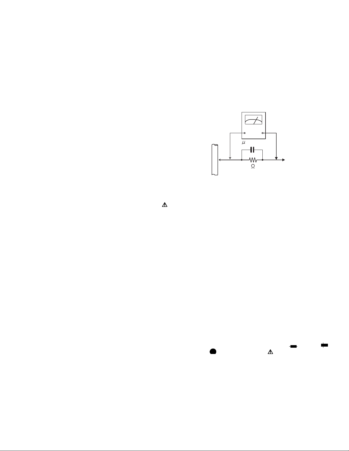
• Alternate check method
Plug the AC line cord directly into the AC outlet. Use an
AC voltmeter having, 1,000Ω per volt or more sensitivity
in the following manner. Connect a 1,500Ω 10W resistor
paralleled by a 0.15µF AC-type capacitor between an ex-
posed metal part and a known good earth ground.
Measure the AC voltage across the resistor with the AC
voltmeter.
Move the resistor connection to each exposed metal
part, particularly any exposed metal part having a return
path to the chassis, and measure the AC voltage across
the resistor. Now, reverse the plug in the AC outlet and
repeat each measurement. Voltage measured any must
not exceed 0.75 V AC (r.m.s.). This corresponds to 0.5
mA AC (r.m.s.).
AC VOLTMETER
(Having 1000
ohms/volts,
or more sensitivity)
0.15 F AC TYPE
Place this
probe on
1500 10W
Good earth ground
1.2 Warning
(1) This equipment has been designed and manufactured to
meet international safety standards.
(2) It is the legal responsibility of the repairer to ensure that
these safety standards are maintained.
(3) Repairs must be made in accordance with the relevant
safety standards.
(4) It is essential that safety critical components are replaced
by approved parts.
(5) If mains voltage selector is provided, check setting for local
voltage.
1.3 Caution
Burrs formed during molding may be left over on some parts
of the chassis.
Therefore, pay attention to such burrs in the case of preforming repair of this system.
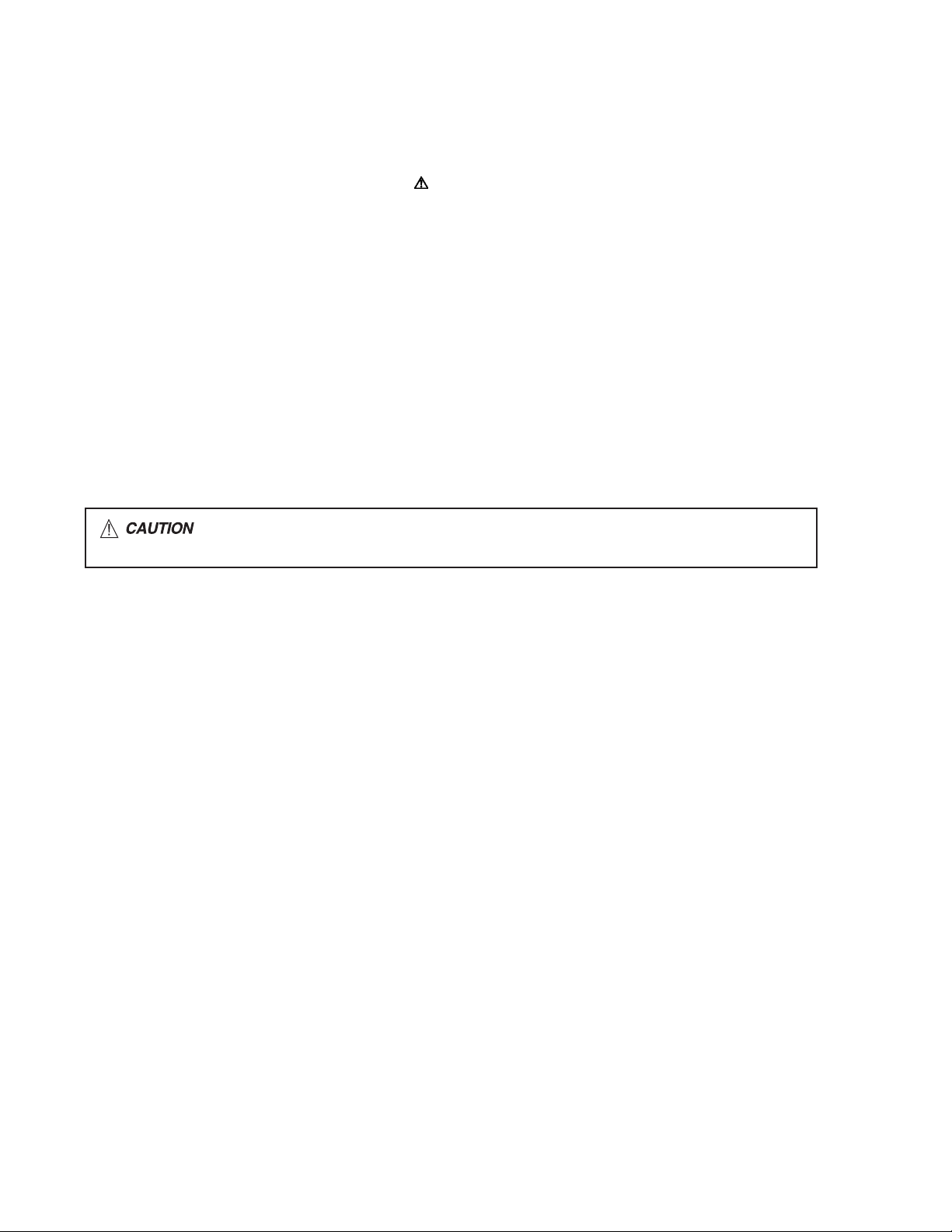
1.4 Critical parts for safety
In regard with component parts appearing on the silk-screen
printed side (parts side) of the PWB diagrams, the parts that are
printed over with black such as the resistor ( ), diode ( )
and ICP ( ) or identified by the " " mark nearby are critical
for safety. When replacing them, be sure to use the parts of the
same type and rating as specified by the manufacturer.
(This regulation dose not Except the J and C version)
each exposed
metal part.
(No.MB306)1-3
Page 4
1.5 Safety Precautions (U.K only)
(1) This design of this product contains special hardware and many circuits and components specially for safety purposes. For con-
tinued protection, no changes should be made to the original design unless authorized in writing by the manufacturer. Replacement parts must be identical to those used in the original circuits.
(2) Any unauthorised design alterations or additions will void the manufacturer's guarantee; furthermore the manufacturer cannot
accept responsibility for personal injury or property damage resulting therefrom.
(3) Essential safety critical components are identified by ( ) on the Parts List and by shading on the schematics, and must never
be replaced by parts other than those listed in the manual. Please note however that many electrical and mechanical parts in
the product have special safety related characteristics. These characteristics are often not evident from visual inspection. Parts
other than specified by the manufacturer may not have the same safety characteristics as the recommended replacement parts
shown in the Parts List of the Service Manual and may create shock, fire, or other hazards.
(4) The leads in the products are routed and dressed with ties, clamps, tubings, barriers and the like to be separated from live parts,
high temperature parts, moving parts and/or sharp edges for the prevention of electric shock and fire hazard. When service is
required, the original lead routing and dress should be observed, and it should be confirmed that they have been returned to
normal, after re-assembling.
1.5.1 Warning
(1) Service should be performed by qualified personnel only.
(2) This equipment has been designed and manufactured to meet international safety standards.
(3) It is the legal responsibility of the repairer to ensure that these safety standards are maintained.
(4) Repairs must be made in accordance with the relevant safety standards.
(5) It is essential that safety critical components are replaced by approved parts.
(6) If mains voltage selector is provided, check setting for local voltage.
Burrs formed during molding may be left over on some parts of the chassis. Therefore,
pay attention to such burrs in the case of preforming repair of this system.
1-4 (No.MB306)
Page 5
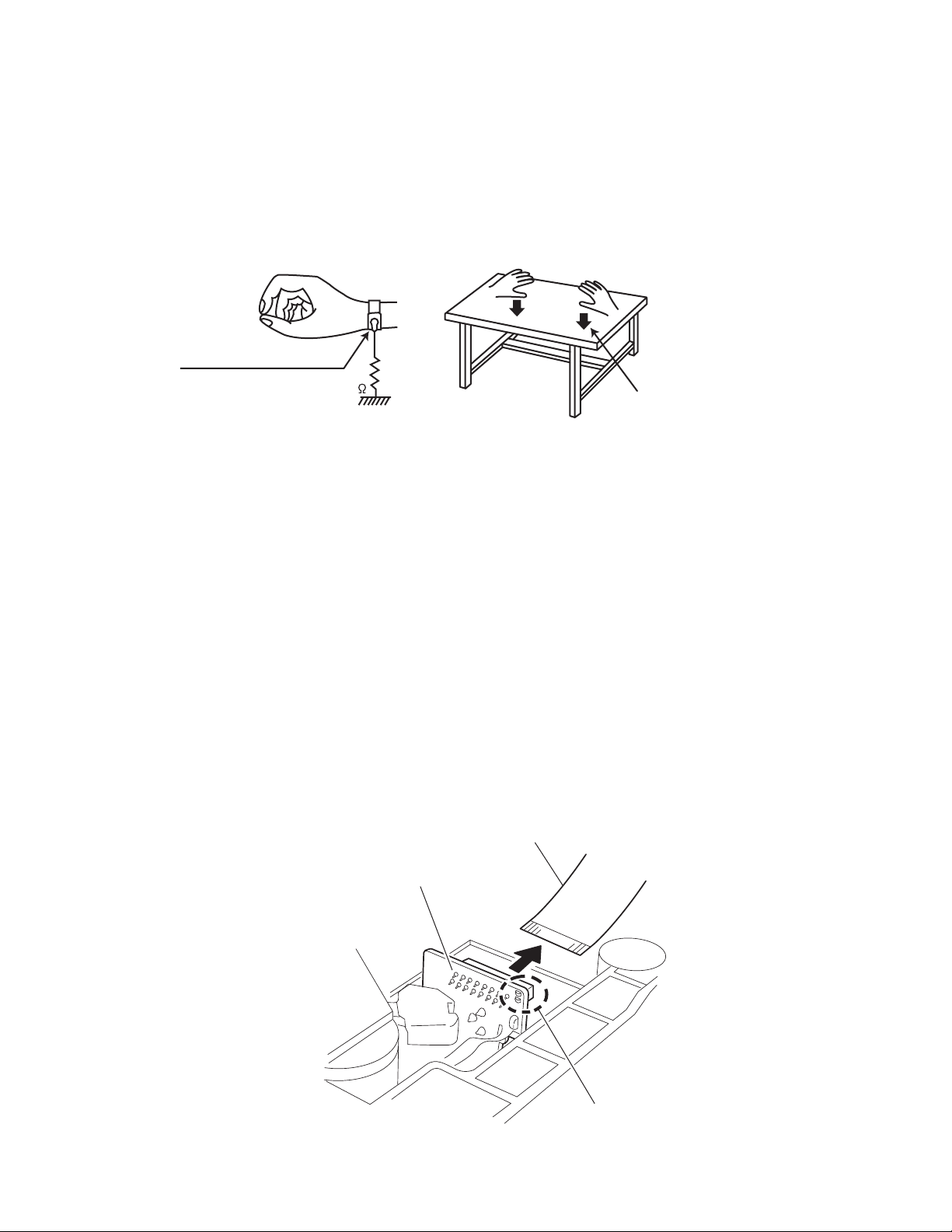
1.6 Preventing static electricity
Electrostatic discharge (ESD), which occurs when static electricity stored in the body, fabric, etc. is discharged, can destroy the laser
diode in the traverse unit (optical pickup). Take care to prevent this when performing repairs.
1.6.1 Grounding to prevent damage by static electricity
Static electricity in the work area can destroy the optical pickup (laser diode) in devices such as laser products.
Be careful to use proper grounding in the area where repairs are being performed.
(1) Ground the workbench
Ground the workbench by laying conductive material (such as a conductive sheet) or an iron plate over it before placing the
traverse unit (optical pickup) on it.
(2) Ground yourself
Use an anti-static wrist strap to release any static electricity built up in your body.
(caption)
Anti-static wrist strap
1M
Conductive material
(conductive sheet) or iron palate
(3) Handling the optical pickup
• In order to maintain quality during transport and before installation, both sides of the laser diode on the replacement optical
pickup are shorted. After replacement, return the shorted parts to their original condition.
(Refer to the text.)
• Do not use a tester to check the condition of the laser diode in the optical pickup. The tester's internal power source can easily
destroy the laser diode.
1.7 Handling the traverse unit (optical pickup)
(1) Do not subject the traverse unit (optical pickup) to strong shocks, as it is a sensitive, complex unit.
(2) Cut off the shorted part of the flexible cable using nippers, etc. after replacing the optical pickup. For specific details, refer to the
replacement procedure in the text. Remove the anti-static pin when replacing the traverse unit. Be careful not to take too long a
time when attaching it to the connector.
(3) Handle the flexible cable carefully as it may break when subjected to strong force.
(4) I t is not possible to adjust the semi-fixed resistor that adjusts the laser power. Do not turn it.
1.8 Attention when traverse unit is decomposed
*Please refer to "Disassembly method" in the text for the pickup unit.
• Apply solder to the short land sections before the flexible wire is disconnected from the connecto on the servo board. (If the flexible
wire is disconnected without applying solder, the pickup may be destroyed by static electricity.)
• In the assembly, be sure to remove solder from the short land sections after connecting the flexible wire.
Card wire
CD pickup board
Short-circuit point
(No.MB306)1-5
Page 6
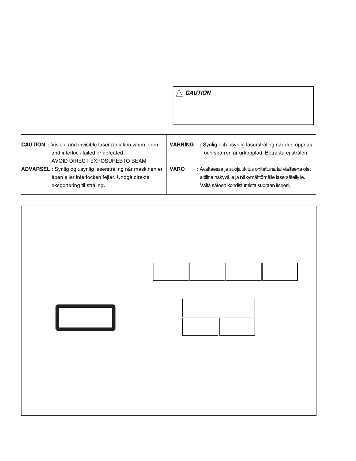
1.9 Important for laser products
!
1.CLASS 1 LASER PRODUCT
2.DANGER : Invisible laser radiation when open and inter
lock failed or defeated. Avoid direct exposure to beam.
3.CAUTION : There are no serviceable parts inside the
Laser Unit. Do not disassemble the Laser Unit. Replace
the complete Laser Unit if it malfunctions.
4.CAUTION : The CD,MD and DVD player uses invisible
laser radiation and is equipped with safety switches which
prevent emission of radiation when the drawer is open and
the safety interlocks have failed or are defeated. It is
dangerous to defeat the safety switches.
5.CAUTION : If safety switches malfunction, the laser is able
to function.
6.CAUTION : Use of controls, adjustments or performance of
procedures other than those specified here in may result in
hazardous radiation exposure.
Please use enough caution not to
see the beam directly or touch it
in case of an adjustment or operation
check.
REPRODUCTION AND POSITION OF LABELS
WARNING LABEL
CAUTION : Visible and Invisible
laser radiation when open and
interlock failed or defeated.
AVOID DIRECT EXPOSURE TO
BEAM. (e)
CLASS 1
LASER PRODUCT
ADVARSEL : Synlig og usynlig
laserstråling når maskinen er
åben eller interlocken fejeler.
Undgå direkte eksponering til
stråling. (d)
CAUTION : Visible and Invisible
laser radiation when open and
interlock failed or defeated.
AVOID DIRECT EXPOSURE TO
BEAM. (e)
VARNING : Synlig och
osynling laserstrålning när
den öppnas och spärren är
urkopplad. Betrakta ej
strålen. (s)
VARNING : Synlig och
osynling laserstrålning när
den öppnas och spärren är
urkopplad. Betrakta ej
strålen. (s)
VARO : Avattaessa ja suojalukitus
ohitettuna tai viallisena olet alttiina
näkyvälle ja näkymättömälle
lasersäteilylle. Vältä säteen
kohdistumista suoraan itseesi. (f)
ADVARSEL : Synlig og usynlig
laserstråling når maskinen er
åben eller interlocken fejeler.
Undgå direkte eksponering til
stråling. (d)
VARO : Avattaessa ja suojalukitus
ohitettuna tai viallisena olet alttiina
näkyvälle ja näkymättömälle
lasersäteilylle. Vältä säteen
kohdistumista suoraan itseesi. (f)
1-6 (No.MB306)
Page 7

SECTION 2
SPECIFIC SERVICE INSTRUCTIONS
This service manual does not describe SPECIFIC SERVICE INSTRUCTIONS.
(No.MB306)1-7
Page 8
SECTION 3
DISASSEMBLY
3.1 Main body
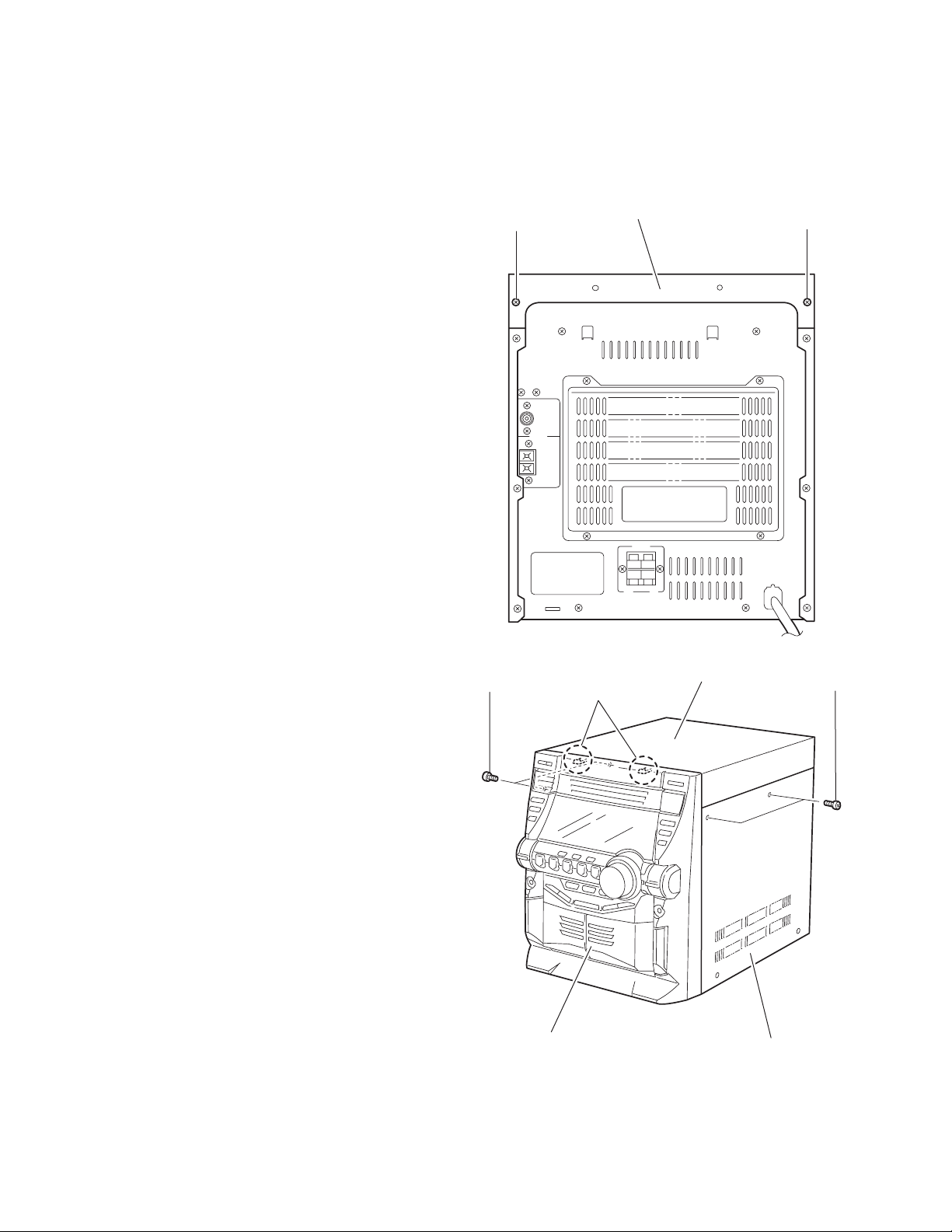
3.1.1 Removing the top cover / side cover (R) and (L)
(See Fig.1 to 6)
(1) From the back of the body, remove the two screws A at-
taching the top cover.
(2) From both sides of the body, remove the four screws B at-
taching the top cover and the side cover (R) and (L). Move
the top cover in the direction of the arrow to release from
the front panel at the two joints a.
(3) Remove the six screws D on the back of the body and the
two screws E on the side of the body. Move the side cover
(R) and (L) backward to release the four joints b on the bottom of the side covers.
A
Top cover
A
B
Front panel assembly
a
Fig.1
Fig.2
Top cover
B
Side cover (R)
1-8 (No.MB306)
Page 9
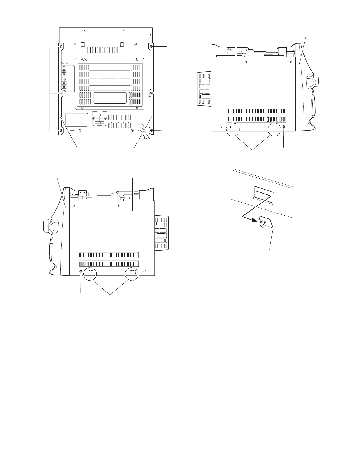
D D
Side cover (L)
Front panel assembly
Side cover (R)
Front panel assembly
E
Fig.3
b
Fig.4
Side cover (L)
Side cover (R)
b
E
Fig.5
Joint b
Fig.6
(No.MB306)1-9
Page 10
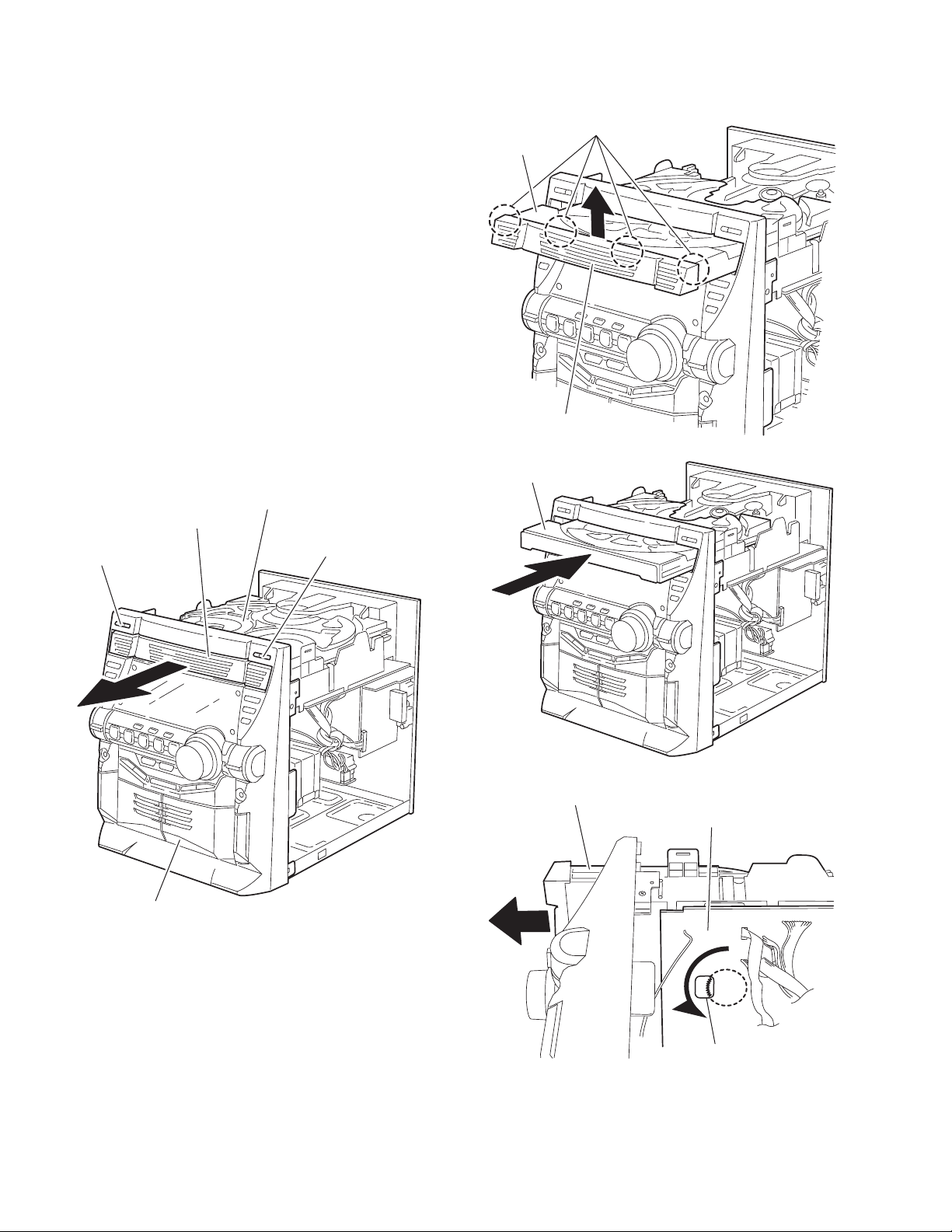
3.1.2 Removing the CD fitting
(See Fig.7 to 9)
• Prior to performing the following procedure, remove the top
cover / side cover (R) and (L).
Caution:
For preventing from damage, make sure to remove the CD fit-
ting before detaching the CD changer mechanism unit.
(1) Push STANDBY / ON key to turn power on.
(2) Push CD TRAY EJECT key.
(3) Move the CD fitting in the direction of the arrow to release
from the CD tray at two joints d.
(4) Push STANDBY / ON key to close the tray.
3.1.3 Removing the CD fitting
(See Fig.8 to 10)
< How to eject the CD tray without turning power on >
• Prior to performing the following procedure, remove the top
cover / side cover(R) and (L).
(1) Turn over the CD changer mechanism unit and turn the
loading pulley gear at e in the inner part of the notch of the
main board to move the CD tray forward.
(2) Move the CD fitting in the direction of the arrow to release
from the CD tray at two joint d.
(3) Manually push and close the CD tray.
CD changer mechanism unit
CD fitting
d
CD tray
CD fitting
Fig.8
CD tray
STANDBY / ON
Front panel assembly
CD TRAY EJECT
Fig.9
CD changer mechanism
Main board
Fig.7
1-10 (No.MB306)
e
Loading pullygear
Fig.10
Page 11
3.1.4 Removing the CD changer mechanism unit
(See Fig.11 to 16)
• Prior to performing the following procedure, remove the top
cover / side cover (R) and (L), and the CD fitting.
(1) Disconnect the wire from connector CN601
board on the right side of the body.
(2) Disconnect the wire from connector CN504
board on the inner side of the front panel.
(3) Disconnect the wire from connector CN801
on the power board.
CN803
(4) Disconnect the wire from connector CN100, CN101 and
on the main board at the bottom of the CD changer
CN207
mechanism unit, and disconnect the card wire from connector CN103
wires.
(5) From the side of the body, remove the two screws F attach-
ing the CD changer mechanism unit.
(6) From the back of the body, remove the two screws G at-
taching the CD changer mechanism unit.
(7) Move the CD changer mechanism unit in the direction of
the arrow while pulling the rear panel backward, and remove the CD changer mechanism unit.
. If necessary, release the band attaching the
on the turner
on the AUX
, CN802 and
CD changer mechanism unit
F
AUX board
CN504
Front panel assembly
Rear panel
Rear panel
Turner board
CN601
Fig.11
CD changer mechanism unit
Front panel assembly
Fig.12
F
(No.MB306)1-11
Page 12

AUX board
CN504
CD changer mechanism unit
Main board
Front panel assembly
CD changer mechanism unit
Fig.13
CN801
G
CN100
CN207
Fig.15
Rear panel
CN103
CN101
G
CN802
1-12 (No.MB306)
Fig.16
Power board
CN803
Fig.14
Page 13

3.1.5 Removing the tuner board
(See Fig.17, 18)
• Prior to performing the following procedure, remove the top
cover / side cover (R) and (L).
(1) Disconnect the wire from connector CN601
board.
(2) From the back of the body, remove the two screws H, the
two screws J and the two screws K attaching the tuner
board respectively.
(3) Remove the two screws L attaching the tuner board holder.
Caution:
You can remove the tuner board without removing the CD
changer mechanism unit and the rear panel.
on the tuner
H
K
J
Tuner board
CN601
Fig.17
Tuner board holder
L
Fig.18
Tuner board
(No.MB306)1-13
Page 14

3.1.6 Removing the speaker terminal board
(See Fig.19, 20)
• Prior to performing the following procedure, remove the top
cover / side cover (R) and (L).
(1) Disconnect the wire from connector CN901 on the speaker
terminal board.
(2) From the back of the body, remove the two screws M at-
taching the speaker terminal board.
Reference:
You can remove the speaker terminal board without detaching
the CD changer mechanism unit and the rear panel.
Speaker terminal board
Rear panel
CN901
Fig.19
Rear cover
M
Rear panel
Fig.20
1-14 (No.MB306)
Page 15

3.1.7 Removing the front panel assembly
(See Fig.21 to 24)
• Prior to performing the following procedure, remove the top
cover / side cover (R) and (L), the CD fitting / CD changer
mechanism unit.
(1) Disconnect the wire from connector CN861
board.
(2) Disconnect the earth wire from the base chassis on the bot-
tom of the right side of the body.
(3) From the bottom of the body, remove the two screws N at-
taching the front panel assembly.
(4) Release the two joints f on the side of the body and the joint
g on the bottom using a screwdriver, and remove the front
panel assembly forward.
on the power
Rear panel
Power board
CN861
Fig.21
Front panel assembly
f
Earth wire
Fig.22
(No.MB306)1-15
Page 16

Front panel assembly
Fig.23
Front panel assembly
f
N
N
Fig.24
1-16 (No.MB306)
Page 17

3.1.8 Removing the POWER switch board / CD switch board
(See Fig.25, 26)
• Prior to performing the following procedure, remove the front
panel assembly.
(1) Remove the two screws P and the three screws Q attach-
ing the bracket.
(2) Remove the screws R attaching the POWER switch board.
(3) Remove the screw T attaching the CD switch board.
P
Q
Front panel assembly
Fig.25
Bracket
P
CD switch boardPower switch board
RT
3.1.9 Removing the REC select switch board / PROGRAM select switch board
(See Fig.27)
• Prior to performing the following procedure, remove the front
panel assembly.
(1) Remove the three screws U attaching the REC select
switch board.
(2) Remove the three screws Y attaching the CD switch board.
Y
Y
PROGRAM select
switch boaed
Front panel assembly
Fig.26
Front panel assembly
U
U
REC select
switch boaed
Fig.27
(No.MB306)1-17
Page 18

3.1.10 Removing the LCD board / STANDBY board
(See Fig.28, 29)
• Prior to performing the following procedure, remove the front
panel assembly.
(1) Remove the four screws A’ attaching the LCD board and
disconnect the wire from connector CN505
(2) Remove the two screws B’ attaching the STANDBY board.
.
Front panel assembly
A'
CN505
LCD board
Front panel assembly
A'
Fig.28
STANDBY board
B'
Fig.29
1-18 (No.MB306)
Page 19

3.1.11 Removing the system board / headphone board / AUX board
(See Fig.30 to 34)
• Prior to performing the following procedure, remove the front
panel assembly.
(1) Pull out the volume knob on the front side of the front panel
assembly. Release the three tabs of the knob holder and
pull out the knob holder.
(2) Remove the nut and the washer from the volume shaft.
(3) From the back of the front panel assembly, remove the sev-
enteen screws D’ attaching the system board.
(4) Remove the screw E’ attaching the headphone board fit-
ting plate and pull out the headphone board.
(5) Remove the screw F’ attaching the AUX board fitting plate
and pull out the AUX board.
Washer
Nut
Volume knob
Front panel assembly
Knob holder
Ta b
Fig.30
Front panel assembly
D'
D'
System board
D'
D'
Fig.31
(No.MB306)1-19
Page 20

Front panel assembly
Cassette mechanism assembly
G'
Headphone board
Fig.32
Front panel assembly
E'
Fitting plate
Front panel assembly
G'
Fig.34
F'
Fitting plate
1-20 (No.MB306)
AUX board
Fig.33
Page 21

3.1.12 Removing the cassette mechanism assembly
(See Fig.35)
• Prior to performing the following procedure, remove the front
panel assembly.
(1) Remove the six screws G’ attaching the cassette mecha-
nism assembly.
Rear cover
H' H'
H'
Rear panel
Fig.35
H'
(No.MB306)1-21
Page 22

3.1.13 Removing the rear cover / rear panel
(See Fig.36 to 38)
• Prior to performing the following procedure, remove the top
cover / side cover (R) and (L), the CD fitting / CD changer
mechanism unit.
(1) From the back of the body, remove the four screws H’ at-
taching the rear cover.
(2) From the back of the body, remove the two screws J’ at-
taching the rear panel.
(3) Release the two joints h on the bottom of the right and left
sides of the rear panel, and remove the rear panel. The
rear panel comes off with the power board and the heat
sink.
Rear panel
J'
Fig.36
Rear panel
h
Fig.37
1-22 (No.MB306)
Raer panel
h
Fig.38
Page 23

3.1.14 Removing the heat sink / power board
(See Fig.39 to 42)
• Prior to performing the following procedure, remove the top
cover / side cover (R) and (L), the CD fitting / CD changer
mechanism unit, the rear cover / rear panel.
(1) From the inner side of the rear panel, remove the four
screws K’ attaching the heat sink. Move the heat sink in the
direction of the arrow along the notch of rear panel and remove it with the heat sink and the power board forward.
(2) Remove the four screws M’ and the four screws N’ attach-
ing the board bracket (R) and (L).
(3) Remove the two screws P’ and the two screws Q’ attaching
the power board.
(4) If necessary, unsolder the power cord and the wire extend-
ing from the power transformer assembly.
Raer panel
P'
Heat sink
Q'
M'
Board bracket (R)
M'
Board bracket (L)
Power board
Fig.41
Board bracket (R) Board bracket (L)
Heat sink
K'
Raer panel
Fig.39
Power board
N' N'
K'
Power board
Soldered parts
Fig.42
Heat sink
Power board
Fig.40
(No.MB306)1-23
Page 24

3.1.15 Removing the power transformer assembly
(See Fig.43)
• Prior to performing the following procedure, remove the top
cover / side cover (R) and (L), the CD fitting / CD changer
mechanism unit and the rear cover / rear panel.
(1) Move the cord stopper in the direction of the arrow and dis-
connect the power cord.
(2) Remove the four screws R’ attaching the power transform-
er assembly.
If necessary, unsolder each wire.
Power transformer
R'
R'
Fig.43
1-24 (No.MB306)
Page 25

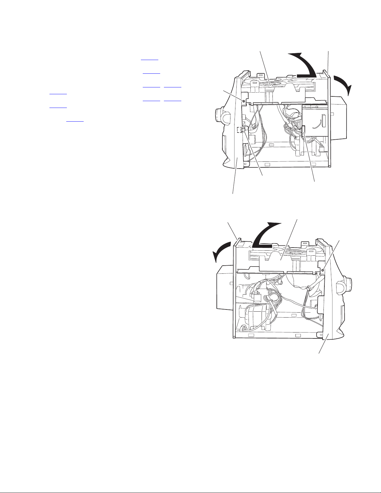
3.1.16 Removing the main board
(See Fig.44 to 46)
• Prior to performing the following procedure, remove the top
cover / side cover (R) and (L), the CD fitting / CD changer
mechanism unit.
Caution:
Before disconnecting the card wire from the CD pickup board
and connector CN401
the short-circuit point on the CD pickup board. If you do not follow this instruction, the pick up may be damaged.
(1) From the bottom of the CD changer mechanism unit, re-
move the two screws T’ and the four screws U’ attaching
the main board.
(2) Disconnect the wire from connector on the main board.
(3) Move the main board in the direction of the arrow as show
in Fig.45, disconnect the wire from connector on the motor
board in the inner part of the main board.
(4) Move the main board turning in the direction of the arrow
ash shown in Fig.45.
(5) Solder the short-circuit point on the CD pickup board and
disconnect the wire from the CD pickup board.
Caution:
When reattaching the main board, make sure to connect the
card wire to connector CN401
pickup board before unsoldering the short-circuit point.
CD changer mechanism unit
on the main board, make sure to solder
on the main board and to the CD
Main board
Main board
CD changer
mechanism unit
CW3
Motor board
CD pickup board
Short-circuit point
Fig.45
Card wire
T'
T'
U'U'
Short-circuit point
Fig.46
Connector
Fig.44
(No.MB306)1-25
Page 26

3.2 Speaker
3.2.1 Removing the front cabinet
(See Fig.1 to 3)
Caution:
When performing the following procedure, apply the cloth to
the product for preventing it from damage.
(1) Put the screwdriver into the two notch a at the bottom of the
speaker, and remove the front panel assembly while pulling out the six bosses on the inner side of the front panel
assembly forward.
Caution:
The six bosses are attached with bond. Apply the cloth
to the product for protect from damage, and pull out each
boss carefully.
(2) Disconnect the two wires of the main speaker terminal from
the back of the front panel assembly.
(3) Disconnect the two wires of the sub speaker terminal from
the back of the front panel assembly.
aa
Boss
Boss
Fig.1
Front panel assembly
Sub speaker terminal
Boss
Fig.2
1-26 (No.MB306)
Main speaker terminalh
Fig.3
Page 27

3.2.2 Removing the main speaker / sub speaker
A
(See Fig.4)
• Prior to performing the following procedure, remove the front
cabinet.
(1) Remove the four screws A attaching the main speaker.
(2) Remove the two screws B attaching the sub speaker.
Sub speaker
B
Main speaker
Fig.4
A
(No.MB306)1-27
Page 28

SECTION 4
ADJUSTMENT
4.1 Measurement Instruments Required for Adjustment
(1) AM signal generator
(2) FM signal generator
(3) Intermadiate frequency sweep generator
(4) FM stereo signal generator
(5) Low-frequency oscillator
(oscillation frequency 50Hz-20kHz, 0dB output with 600 Ω impedance)
(6) Attenuator (600 Ω impedance)
(7) Electrinic voltmeter
(8) Distortion meter
(9) Wow & Flutter meter
(10) Frequency counter meter
(11) Test tape
VT712 : for Tape speed and wow flutter
VT724 : for reference level
VT703L : for head azimuth adjustment
Blank tape for recording
4.2 Measurement conditons
Radio section
FM 1 kHz, 22.5 kHz deviation
FM STEREO : 1 kHz, 67.5 kHz deviation pilot signal 7.5 kHz
AM : 1 kHz, 30 % modulation
Reference output :Headphone output (0.15V) 32 Ω
Speaker output 1W (2.5V) 6 Ω
Cassette amp section : 1 kHz
Reference output :Headphone output (0.15V) 32 Ω
Speaker output 1 W (2.5V) 6 Ω
Standard mode of function knob:Press TAPE knob of select TAPE mode
CD section
CD test disc : CTS-1000
1-28 (No.MB306)
Page 29

4.3 Cassette amp section
Item Measuring condition Check and adjustment procedure Standard value Adjusting part
Head azimuth
adjustment
Tape speed and
wow/flutter check
and adjustment
Bias frequency
chek
Rec anf PB
frequency
response
adjustment
Test tape : VT703L
Signal output terminal :
SPK out
(with 6 ohm load)
Test tap : VT712
Signal output terminal :
SPK out
(with 6 ohm load)
Test tape : B
Signal output terminal :
Cassette REC/Play
head
Test tape : Brank tape
Signal input :
CD 1 kHz -20 dBs
Signal output terminal :
SPK out
(with 6 ohm load)
1. Playback the test tape VT703L.
2. Adjust the head azimuth adjusting screw so
that the phase difference between the R and
L channels is minimized at an output level
that is within (20dB of the maximum output
level. After this adjustment. Lock the head
azimuth adjusting screw with screw sealant
to cover more than a half of the screw head.
3. When the head azimuth is maladjusting
correct it with the head azimuth adjusting
screw.
1. Playback the test tape VT712 by the end
portion.
2. Connect a frequency counter and check that
it reads between 2940 and 3090 Hz. If not,
adjust the frequency with the motor
semifixed resistor.
3. Check that the wow/flutter is within 0.35%
(unweigthed).
Set the Tuner or CD function and with TAPE
to record check to see if the frequency at the
measuring point REC-IF is 85 kHz if not adjust
T100 until the frequency counter indicates
85 kHz+1kHz-1kHz.
Record the reference CD 1 kHz signal and 10
kHz signal alternately repeatedly. While playing
back the recorded signal of the 1 kHz signal
doffer from that of the 10 kHz signal by within
(0+3dB-6dB).
Output level :
Within (2 dB of
Maximum output
level.
*Phase difference
R and L channels :
Minimum
2940 to 3090 Hz
within 0.35%
(unweighted)
Level difference for
1 kHz signal :
within (0+3dB-6dB)
Level difference for
1 kHz signal :
within (0+3dB-6dB)
Head azimuth
adjusting screw
(To be use only
after head
replacement)
Tape speed
Motor semifixed
resistor
Check only
4.4 Tuner section (B/EV version)
Item Measuring condition Check and adjustment procedure Standard value Adjusting part
AM IF adjustment
AM tracking
adjustment
FM tracking
Signal input :
Loop antenna
Signal output :
IC602 pin 16
Signal input :
Loop antenna
signal output :
H.phone out
(with 32 ohm load)
Signal input :
Analog antenna
FM ANT
Fm GND
signal output :
H.phone out
(with 32 ohm load)
1. Set the intermediate frequency sweep
generator to AM 450 kHz.
2. Adjust IFT601 for maximum and center
output
1. Set the TUNER at 522 kHz adjust IFT605
until the test point TP4 voltage at 1.3V+/-.1V.
2. Set the TUNER at 1629 kHz, check the test
point TP4 voltage at 7.0 to 8.0 V.
3. Set the TUNER and S/G at 600 kHz, adjust
ITT606 for maximum output.
4. Set the TUNER and S/G at 1500 kHz, adjust
the VC606 for maximum output.
5. Repeat the avobe step 3 and 4.
1. Set the TUNER at 87.5MHz adjust L604 until
the point TP5 voltage at 1.5V+/-0.1V.
2. Set the TUNER at 108MHz, check the point
TP5 voltage at 7.2-8.0V.
3. Set the TUNER and S/G at 90.1MHz, adjust
L605 for amximum output.
4. Set the TUNER and S/G at 106.1MHz, adjust
the VC604 for maximum output.
IFT601
IFT605
IFT606
VC606
L604
L605
VC604
(No.MB306)1-29
Page 30

4.5 Tuner section (E/EN version)
Item Measuring condition Check and adjustment procedure Standard value Adjusting part
AM IF adjustment
Signal input :
Loop antenna
Signal output :
IC602 pin 18
AM tracking
adjustment
Signal input :
Loop antenna
signal output :
H.phone out
(with 32 ohm load)
FM tracking
Signal input :
Analog antenna
FM ANT
Fm GND
signal output :
H.phone out
(with 32 ohm load)
1. Set the intermediate frequency sweep
generator to AM 450 kHz.
2. Adjust IFT603 for maximum and center
output
1. Set the TUNER at 522 kHz adjust IFT602
until the test point TP13 voltage at
1.3V+/-.1V.
2. Set the TUNER at 1629 kHz, check the test
point TP13 voltage at 7.0 to 8.0 V.
3. Set the TUNER and S/G at 603 kHz, adjust
IFT604 for maximum output.
4. Set the TUNER and S/G at 1404 kHz, adjust
the VC601 for maximum output.
5. Repeat the avobe step 3 and 4.
FM IF :
1. Set the TUNER at FM mode
2. Adjust IFT606 to make the test point (TP4)
swave symmetry.
FM VT :
Check test point TP14 to make sure the voltage
1.5-8.5V.
IFT603
IFT602
IFT604
VC601
4.6 Location of adjusting parts
Cassette mechanism section
(caution) For adjusting any head, be sure to use a screw driver degaussed.
max
Head output signal
Main board
Head
Azimuth adjustment screw
Main board
Adjustment
Cassette motor
Tape speed adj.
-
+
1-30 (No.MB306)
(BIAS FREQUENCY)
T100
REC-F
REC-G
Page 31

Tuner section (B/EV version)
Tuner section (E/EN version)
VC606
AM RF
IFT606
AM RF
IFT605
AM OSC
L604
FM OSC
AM ANT
L605
FM ANT
FM
IFT601
VC604
AM IF
CF604
IH602
FM ANT
IFT602
AM OSC
IFT604
AM RF
VC601
AM RF
IFT603
AM IF
AM ANT
FM VT
(No.MB306)1-31
Page 32

4.7 Flow of functional operation until TOC read
Power ON
Slider turns REST
SW ON.
Laser ON
Focus start
FOK
Turn on focus
servo
Confirm that the voltage at the pin5 of CN402
is 'H' 'L' 'H'.
Check that the voltage at the pin7(CD) of CN401
is 1.8V.
Caution. Before connecting a measuring instrument to
the measuring point, turn the power of the
main unit to OFF.
After performing a measurement and before
disconnecting the measuring instrument,
again turn the power of the main unit to OFF.
(If a measuring instrument is disconnected
while an electric current is being output ot the
main unit, the pickup of the main unit will be
damaged.)
Disc spinning
Radial_error
scaling
PLL Lock
Turn on radial
servo
Read TOC
Check that the voltage at the pin1 and pin2 of
CN402 is 0.65V.
Confirm the eye-pattern at the 'RFO' test point.
1-32 (No.MB306)
Page 33

SECTION 5
TROUBLESHOOTING
This service manual does not describe TROUBLESHOOTING.
(No.MB306)1-33
Page 34

Victor Company of Japan, Limited
AV & MULTIMEDIA COMPANY AUDIO/VIDEO SYSTEMS CATEGORY 10-1,1chome,Ohwatari-machi,Maebashi-city,371-8543,Japan
(No.MB306)
Printed in Japan
WPC
 Loading...