

Page 1
SERVICE MANUAL
COMPACT COMPONENT SYSTEM
MB28420048
MX-KB2,MX-KB1
Area suffix
UW ----------- Brazil,Mexico,Peru
TABLE OF CONTENTS
1 PRECAUTION. . . . . . . . . . . . . . . . . . . . . . . . . . . . . . . . . . . . . . . . . . . . . . . . . . . . . . . . . . . . . . . . . . . . . . . . . 1-3
2 SPECIFIC SERVICE INSTRUCTIONS . . . . . . . . . . . . . . . . . . . . . . . . . . . . . . . . . . . . . . . . . . . . . . . . . . . . . . 1-6
3 DISASSEMBLY . . . . . . . . . . . . . . . . . . . . . . . . . . . . . . . . . . . . . . . . . . . . . . . . . . . . . . . . . . . . . . . . . . . . . . . 1-7
4 ADJUSTMENT . . . . . . . . . . . . . . . . . . . . . . . . . . . . . . . . . . . . . . . . . . . . . . . . . . . . . . . . . . . . . . . . . . . . . . . 1-27
5 TROUBLESHOOTING . . . . . . . . . . . . . . . . . . . . . . . . . . . . . . . . . . . . . . . . . . . . . . . . . . . . . . . . . . . . . . . . . 1-31
COPYRIGHT © 2004 Victor Company of Japan, Limited
No.MB284
2004/8
Page 2

SPECIFICATION
Amplifier Output Power 30 W per channel, min. RMS, driven into 6 Ω at 1kHz, with no more than
10% total harmonic distortion (IEC 268-3)
Input Sensitivity/Impedance (1 kHz) AUX IN:500 mV/51 kΩ
Speaker terminals 6 - 16 Ω
Phones 32 Ω - 1 kΩ
Cassette Deck Section Frequency Response 20 mW/ch output into 32 Ω
Type I (NORMAL) 63 Hz - 12 500 Hz
Wow And Flutter 0.15 % (WRMS)
CD Player CD Capacity 3 CDs
Dynamic Range 85 dB
Signal-To-Noise Ratio 85 dB
Wow And Flutter Unmeasurable
Tuner FM Tuner 87.5 MHz - 108.0 MHz
AM Tuner 530 kHz - 1710 kHz (at AM10 kHz channel space)
531 kHz - 1710 kHz (at AM9 kHz channel space)
Unit Dimensions 276 mm × 315 mm × 456 mm (W/H/D)
Mass Approx. 8 kg
Speaker Specifications
SP-MXKB2/SPMXKB1 (each unit)
Power Specifications Power Requirements AC 110/127/220/230-240V , adjustable with voltage selector, 50/60 Hz
Type 2-way bass-reflex type
Speaker Unit Woofer : 13 cm cone × 1
Tweeter : 5cm cone × 1
Power Handling Capacity 30 W
Impedance 6 Ω
Frequency Range 65 Hz - 20,000 Hz
Sound pressure level 86 dB/W·m
Dimensions 208 mm × 323 mm × 264 mm (W/H/D)
Power Consumption 83 W (power on mode) 13 W (in Standby mode)
Design and specifications are subject to change without notice.
1-2 (No.MB284)
Page 3
SECTION 1
PRECAUTION
1.1 Safety Precautions
(1) This design of this product contains special hardware and
many circuits and components specially for safety purposes. For continued protection, no changes should be made
to the original design unless authorized in writing by the
manufacturer. Replacement parts must be identical to
those used in the original circuits. Services should be performed by qualified personnel only.
(2) Alterations of the design or circuitry of the product should
not be made. Any design alterations of the product should
not be made. Any design alterations or additions will void
the manufacturers warranty and will further relieve the
manufacture of responsibility for personal injury or property
damage resulting therefrom.
(3) Many electrical and mechanical parts in the products have
special safety-related characteristics. These characteristics are often not evident from visual inspection nor can the
protection afforded by them necessarily be obtained by using replacement components rated for higher voltage, wattage, etc. Replacement parts which have these special
safety characteristics are identified in the Parts List of Service Manual. Electrical components having such features
are identified by shading on the schematics and by ( ) on
the Parts List in the Service Manual. The use of a substitute
replacement which does not have the same safety characteristics as the recommended replacement parts shown in
the Parts List of Service Manual may create shock, fire, or
other hazards.
(4) The leads in the products are routed and dressed with ties,
clamps, tubings, barriers and the like to be separated from
live parts, high temperature parts, moving parts and/or
sharp edges for the prevention of electric shock and fire
hazard. When service is required, the original lead routing
and dress should be observed, and it should be confirmed
that they have been returned to normal, after reassembling.
(5) Leakage shock hazard testing
After reassembling the product, always perform an isolation check on the exposed metal parts of the product (antenna terminals, knobs, metal cabinet, screw heads,
headphone jack, control shafts, etc.) to be sure the product
is safe to operate without danger of electrical shock.Do not
use a line isolation transformer during this check.
• Plug the AC line cord directly into the AC outlet. Using a
"Leakage Current Tester", measure the leakage current
from each exposed metal parts of the cabinet, particularly any exposed metal part having a return path to the
chassis, to a known good earth ground. Any leakage current must not exceed 0.5mA AC (r.m.s.).
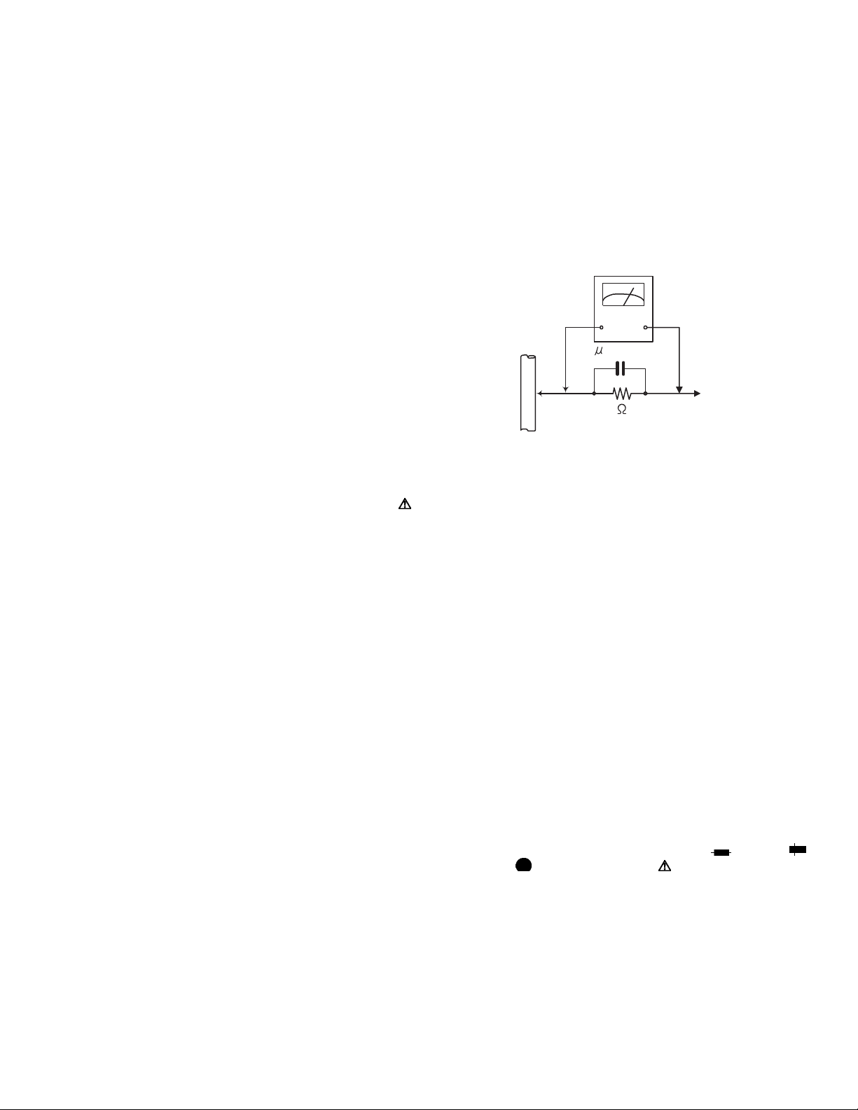
• Alternate check method
Plug the AC line cord directly into the AC outlet. Use an
AC voltmeter having, 1,000Ω per volt or more sensitivity
in the following manner. Connect a 1,500Ω 10W resistor
paralleled by a 0.15µF AC-type capacitor between an ex-
posed metal part and a known good earth ground.
Measure the AC voltage across the resistor with the AC
voltmeter.
Move the resistor connection to each exposed metal
part, particularly any exposed metal part having a return
path to the chassis, and measure the AC voltage across
the resistor. Now, reverse the plug in the AC outlet and
repeat each measurement. Voltage measured any must
not exceed 0.75 V AC (r.m.s.). This corresponds to 0.5
mA AC (r.m.s.).
AC VOLTMETER
(Having 1000
ohms/volts,
or more sensitivity)
0.15 F AC TYPE
Place this
probe on
1500 10W
Good earth ground
1.2 Warning
(1) This equipment has been designed and manufactured to
meet international safety standards.
(2) It is the legal responsibility of the repairer to ensure that
these safety standards are maintained.
(3) Repairs must be made in accordance with the relevant
safety standards.
(4) It is essential that safety critical components are replaced
by approved parts.
(5) If mains voltage selector is provided, check setting for local
voltage.
1.3 Caution
Burrs formed during molding may be left over on some parts
of the chassis.
Therefore, pay attention to such burrs in the case of preforming repair of this system.
1.4 Critical parts for safety
In regard with component parts appearing on the silk-screen
printed side (parts side) of the PWB diagrams, the parts that are
printed over with black such as the resistor ( ), diode ( )
and ICP ( ) or identified by the " " mark nearby are critical
for safety. When replacing them, be sure to use the parts of the
same type and rating as specified by the manufacturer.
(This regulation dose not Except the J and C version)
each exposed
metal part.
(No.MB284)1-3
Page 4
1.5 Preventing static electricity
Electrostatic discharge (ESD), which occurs when static electricity stored in the body, fabric, etc. is discharged, can destroy the laser
diode in the traverse unit (optical pickup). Take care to prevent this when performing repairs.
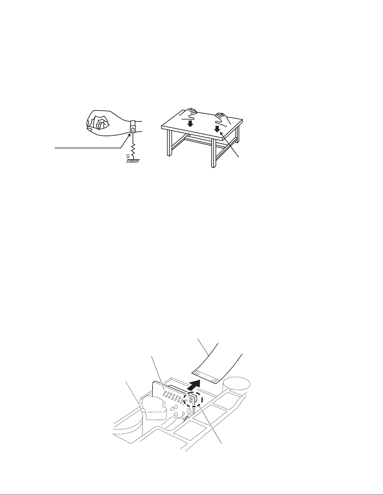
1.5.1 Grounding to prevent damage by static electricity
Static electricity in the work area can destroy the optical pickup (laser diode) in devices such as laser products.
Be careful to use proper grounding in the area where repairs are being performed.
(1) Ground the workbench
Ground the workbench by laying conductive material (such as a conductive sheet) or an iron plate over it before placing the
traverse unit (optical pickup) on it.
(2) Ground yourself
Use an anti-static wrist strap to release any static electricity built up in your body.
(caption)
Anti-static wrist strap
1M
Conductive material
(conductive sheet) or iron palate
(3) Handling the optical pickup
• In order to maintain quality during transport and before installation, both sides of the laser diode on the replacement optical
pickup are shorted. After replacement, return the shorted parts to their original condition.
(Refer to the text.)
• Do not use a tester to check the condition of the laser diode in the optical pickup. The tester's internal power source can easily
destroy the laser diode.
1.6 Handling the traverse unit (optical pickup)
(1) Do not subject the traverse unit (optical pickup) to strong shocks, as it is a sensitive, complex unit.
(2) Cut off the shorted part of the flexible cable using nippers, etc. after replacing the optical pickup. For specific details, refer to the
replacement procedure in the text. Remove the anti-static pin when replacing the traverse unit. Be careful not to take too long a
time when attaching it to the connector.
(3) Handle the flexible cable carefully as it may break when subjected to strong force.
(4) I t is not possible to adjust the semi-fixed resistor that adjusts the laser power. Do not turn it.
1.7 Attention when traverse unit is decomposed
*Please refer to "Disassembly method" in the text for the pickup unit.
• Apply solder to the short land sections before the flexible wire is disconnected from the connecto on the servo board. (If the flexible
wire is disconnected without applying solder, the pickup may be destroyed by static electricity.)
• In the assembly, be sure to remove solder from the short land sections after connecting the flexible wire.
Card wire
1-4 (No.MB284)
CD pickup board
Short-circuit point
Page 5
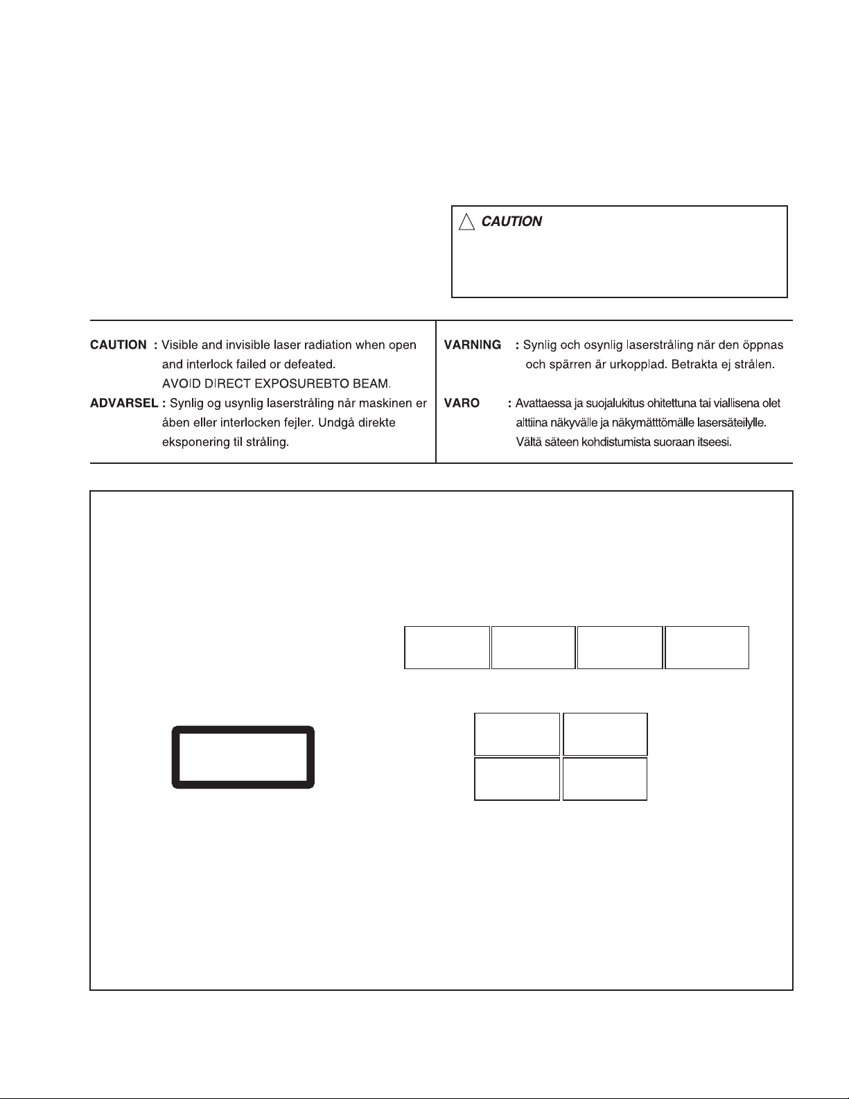
1.8 Important for laser products
!
1.CLASS 1 LASER PRODUCT
2.DANGER : Invisible laser radiation when open and inter
lock failed or defeated. Avoid direct exposure to beam.
3.CAUTION : There are no serviceable parts inside the
Laser Unit. Do not disassemble the Laser Unit. Replace
the complete Laser Unit if it malfunctions.
4.CAUTION : The CD,MD and DVD player uses invisible
laser radiation and is equipped with safety switches which
prevent emission of radiation when the drawer is open and
the safety interlocks have failed or are defeated. It is
dangerous to defeat the safety switches.
5.CAUTION : If safety switches malfunction, the laser is able
to function.
6.CAUTION : Use of controls, adjustments or performance of
procedures other than those specified here in may result in
hazardous radiation exposure.
Please use enough caution not to
see the beam directly or touch it
in case of an adjustment or operation
check.
REPRODUCTION AND POSITION OF LABELS
WARNING LABEL
CAUTION : Visible and Invisible
laser radiation when open and
interlock failed or defeated.
AVOID DIRECT EXPOSURE TO
BEAM. (e)
CLASS 1
LASER PRODUCT
ADVARSEL : Synlig og usynlig
laserstråling når maskinen er
åben eller interlocken fejeler.
Undgå direkte eksponering til
stråling. (d)
CAUTION : Visible and Invisible
laser radiation when open and
interlock failed or defeated.
AVOID DIRECT EXPOSURE TO
BEAM. (e)
VARNING : Synlig och
osynling laserstrålning när
den öppnas och spärren är
urkopplad. Betrakta ej
strålen. (s)
VARNING : Synlig och
osynling laserstrålning när
den öppnas och spärren är
urkopplad. Betrakta ej
strålen. (s)
VARO : Avattaessa ja suojalukitus
ohitettuna tai viallisena olet alttiina
näkyvälle ja näkymättömälle
lasersäteilylle. Vältä säteen
kohdistumista suoraan itseesi. (f)
ADVARSEL : Synlig og usynlig
laserstråling når maskinen er
åben eller interlocken fejeler.
Undgå direkte eksponering til
stråling. (d)
VARO : Avattaessa ja suojalukitus
ohitettuna tai viallisena olet alttiina
näkyvälle ja näkymättömälle
lasersäteilylle. Vältä säteen
kohdistumista suoraan itseesi. (f)
(No.MB284)1-5
Page 6

SECTION 2
SPECIFIC SERVICE INSTRUCTIONS
This service manual does not describe SPECIFIC SERVICE INSTRUCTIONS.
1-6 (No.MB284)
Page 7
SECTION 3
DISASSEMBLY
3.1 Main body
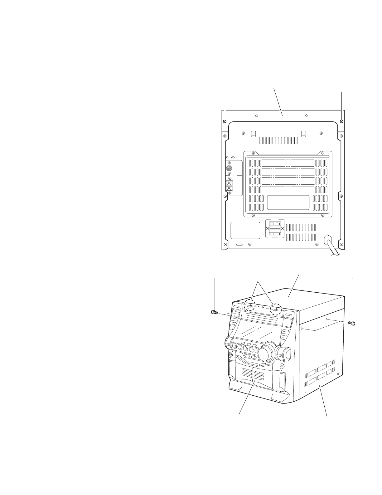
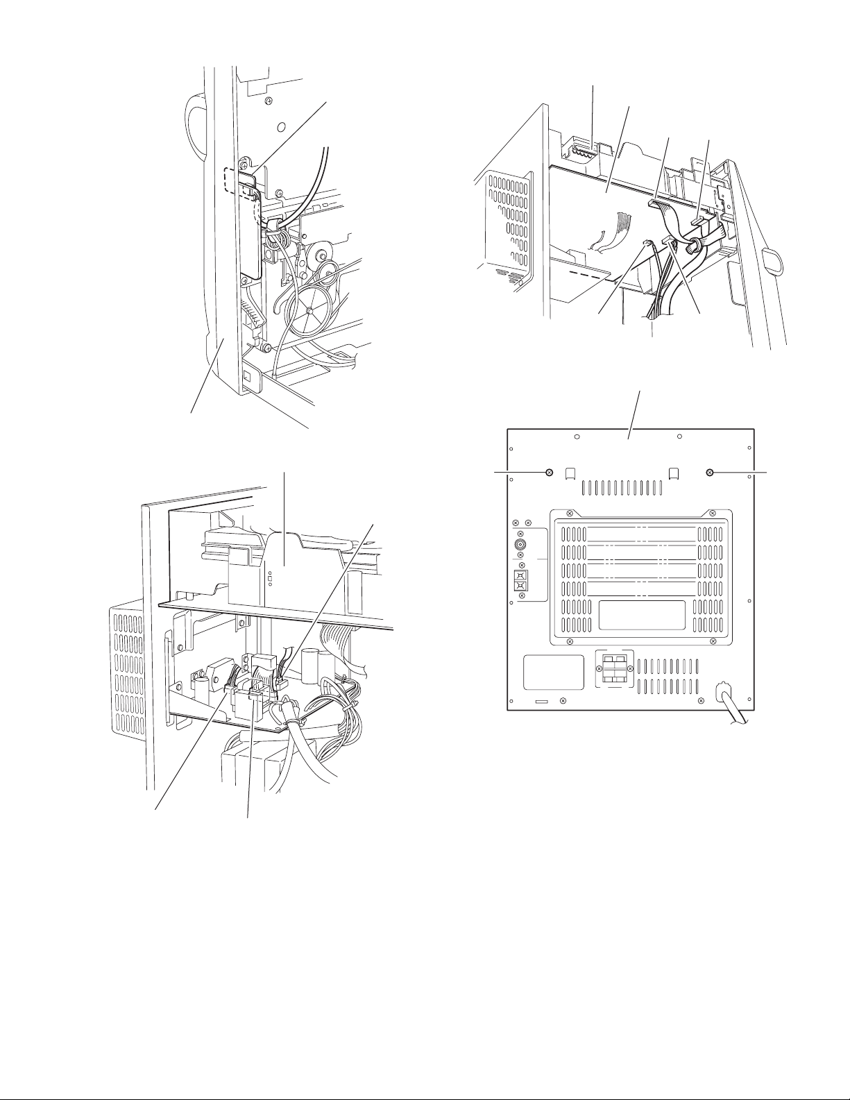
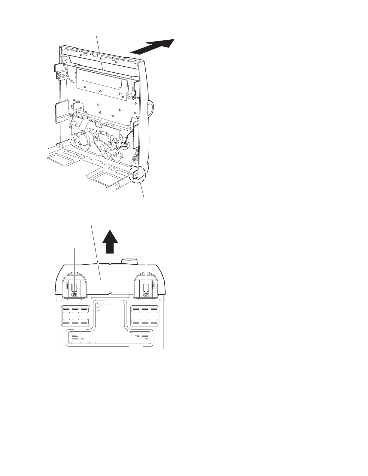
3.1.1 Removing the top cover / side cover (R) and (L)
(See Fig.1 to 6)
(1) From the back of the body, remove the two screws A at-
taching the top cover.
(2) From both sides of the body, remove the four screws B at-
taching the top cover and the side cover (R) and (L). Move
the top cover in the direction of the arrow to release from
the front panel at the two joints a.
(3) Remove the six screws D on the back of the body and the
two screws E on the side of the body. Move the side cover
(R) and (L) backward to release the four joints b on the bottom of the side covers.
A
Top cover
A
B
Front panel assembly
a
Fig.1
Fig.2
Top cover
B
Side cover (R)
(No.MB284)1-7
Page 8
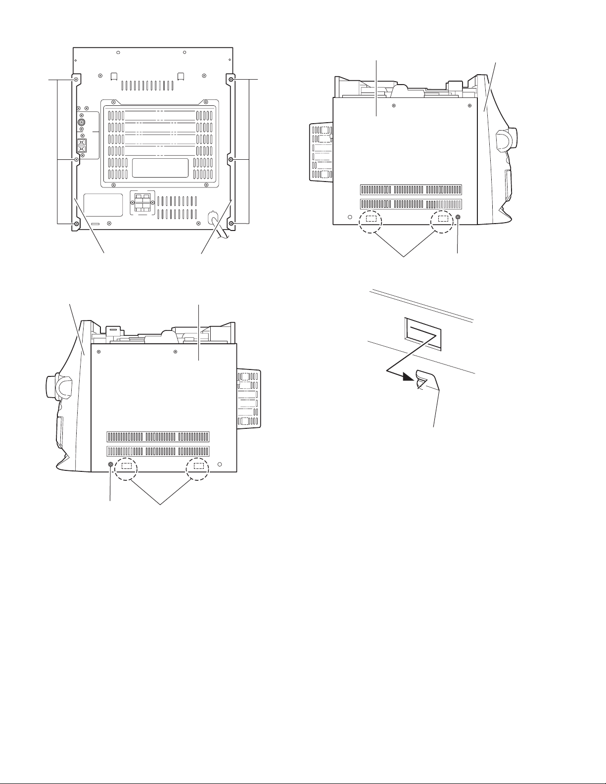
D D
Side cover (L)
Front panel assembly
Side cover (R)
Front panel assembly
E
Fig.3
b
Fig.4
Side cover (L)
Side cover (R)
b
E
Fig.5
Joint b
Fig.6
1-8 (No.MB284)
Page 9
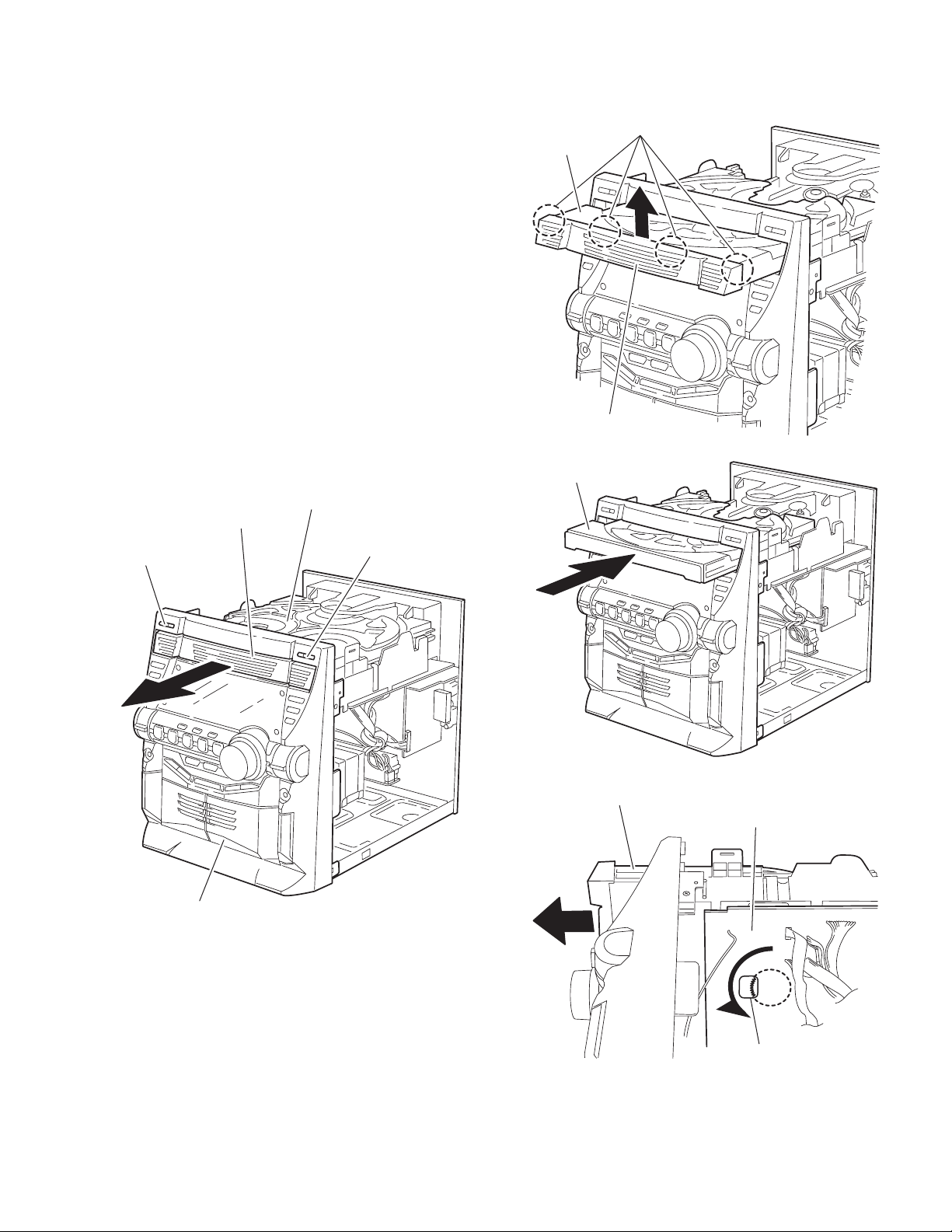
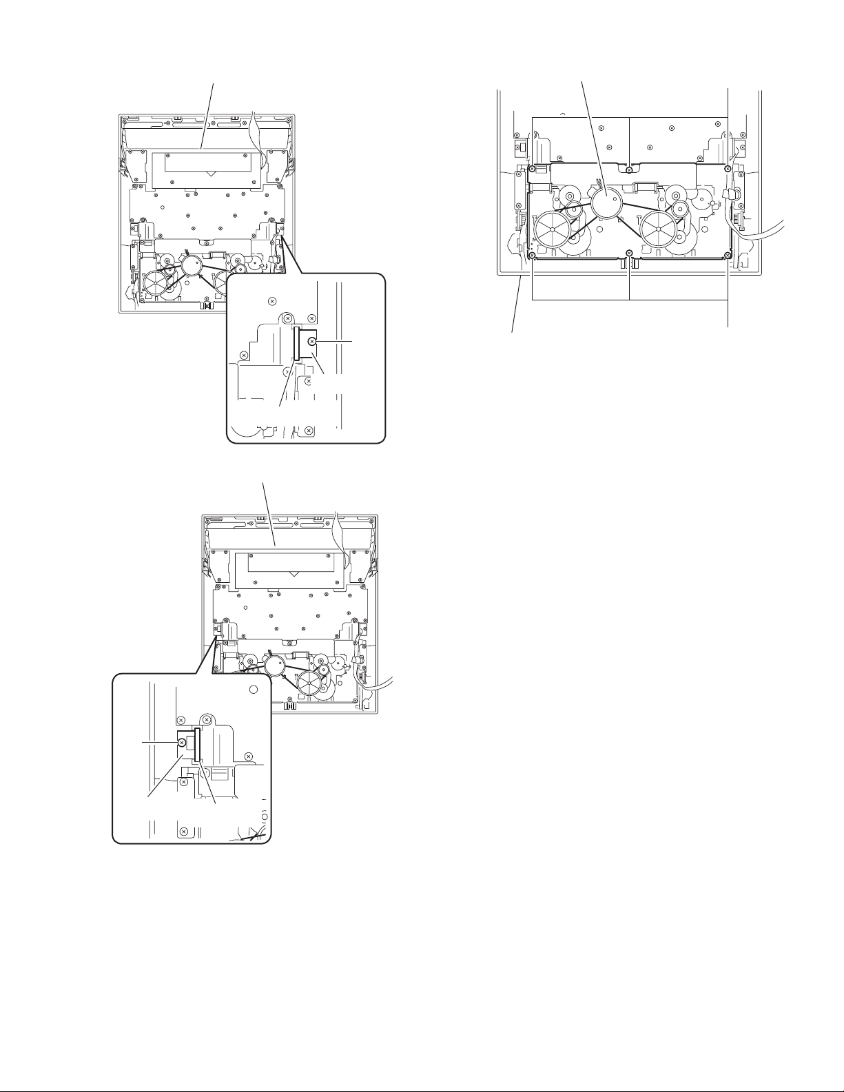
3.1.2 Removing the CD fitting
(See Fig.7 to 9)
• Prior to performing the following procedure, remove the top
cover / side cover (R) and (L).
Caution:
For preventing from damage, make sure to remove the CD fitting before detaching the CD changer mechanism unit.
(1) Push STANDBY / ON key to turn power on.
(2) Push CD TRAY EJECT key.
(3) Move the CD fitting in the direction of the arrow to release
from the CD tray at two joints d.
(4) Push STANDBY / ON key to close the tray.
3.1.3 Removing the CD fitting
(See Fig.8 to 10)
< How to eject the CD tray without turning power on >
• Prior to performing the following procedure, remove the top
cover / side cover(R) and (L).
(1) Turn over the CD changer mechanism unit and turn the
loading pulley gear at e in the inner part of the notch of the
main board to move the CD tray forward.
(2) Move the CD fitting in the direction of the arrow to release
from the CD tray at two joint d.
(3) Manually push and close the CD tray.
CD changer mechanism unit
CD fitting
d
CD tray
CD fitting
Fig.8
CD tray
STANDBY / ON
Front panel assembly
CD TRAY EJECT
Fig.9
CD changer mechanism
Main board
Fig.7
Loading pullygear
Fig.10
e
(No.MB284)1-9
Page 10
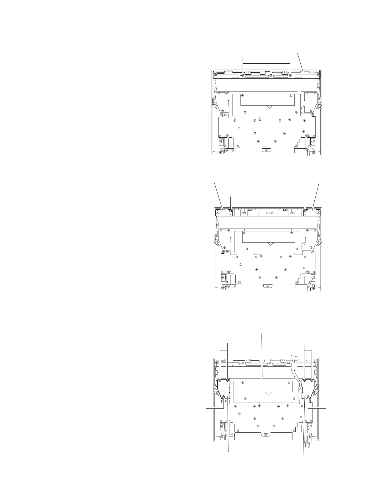
3.1.4 Removing the CD changer mechanism unit
(See Fig.11 to 16)
• Prior to performing the following procedure, remove the top
cover / side cover (R) and (L), and the CD fitting.
(1) Disconnect the wire from connector CN601 on the turner
board on the right side of the body.
(2) Disconnect the wire from connector CN504
board on the inner side of the front panel.
(3) Disconnect the wire from connector CN801
on the power board.
CN803
(4) Disconnect the wire from connector CN100, CN101 and
on the main board at the bottom of the CD changer
CN207
mechanism unit, and disconnect the card wire from connector CN103
wires.
(5) From the side of the body, remove the two screws F attach-
ing the CD changer mechanism unit.
(6) From the back of the body, remove the two screws G at-
taching the CD changer mechanism unit.
(7) Move the CD changer mechanism unit in the direction of
the arrow while pulling the rear panel backward, and remove the CD changer mechanism unit.
. If necessary, release the band attaching the
on the AUX
, CN802 and
CD changer mechanism unit
F
AUX board
CN504
Front panel assembly
Rear panel
Rear panel
Turner board
CN601
Fig.11
CD changer mechanism unit
Front panel assembly
Fig.12
F
1-10 (No.MB284)
Page 11
AUX board
CN504
CD changer mechanism unit
Main board
Front panel assembly
CD changer mechanism unit
Fig.13
CN801
G
CN100
CN207
Fig.15
Rear panel
CN103
CN101
G
CN802
Fig.16
Power board
CN803
Fig.14
(No.MB284)1-11
Page 12
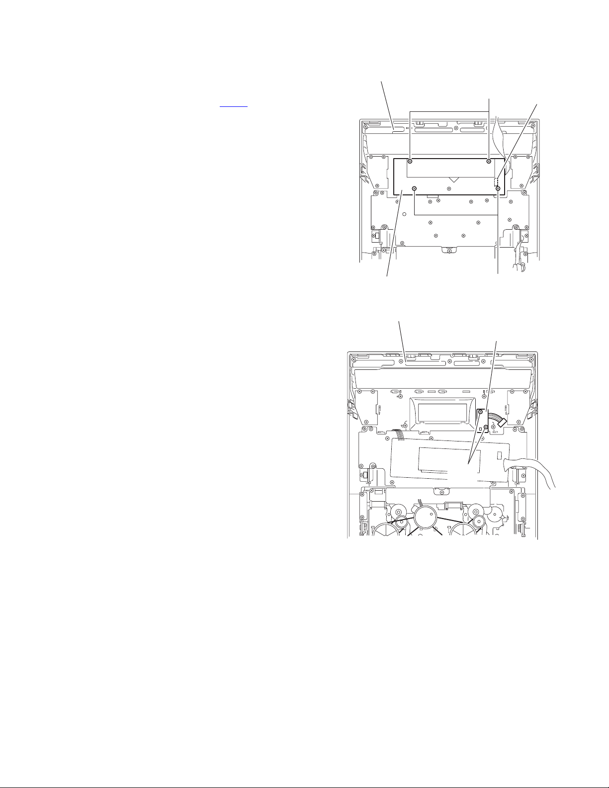
3.1.5 Removing the tuner board
(See Fig.17, 18)
• Prior to performing the following procedure, remove the top
cover / side cover (R) and (L).
(1) Disconnect the wire from connector CN601 on the tuner
board.
(2) From the back of the body, remove the two screws H, the
two screws J and the two screws K attaching the tuner
board respectively.
(3) Remove the two screws L attaching the tuner board holder.
Caution:
You can remove the tuner board without removing the CD
changer mechanism unit and the rear panel.
H
K
J
Tuner board
CN601
Fig.17
Tuner board holder
L
1-12 (No.MB284)
Tuner board
Fig.18
Page 13
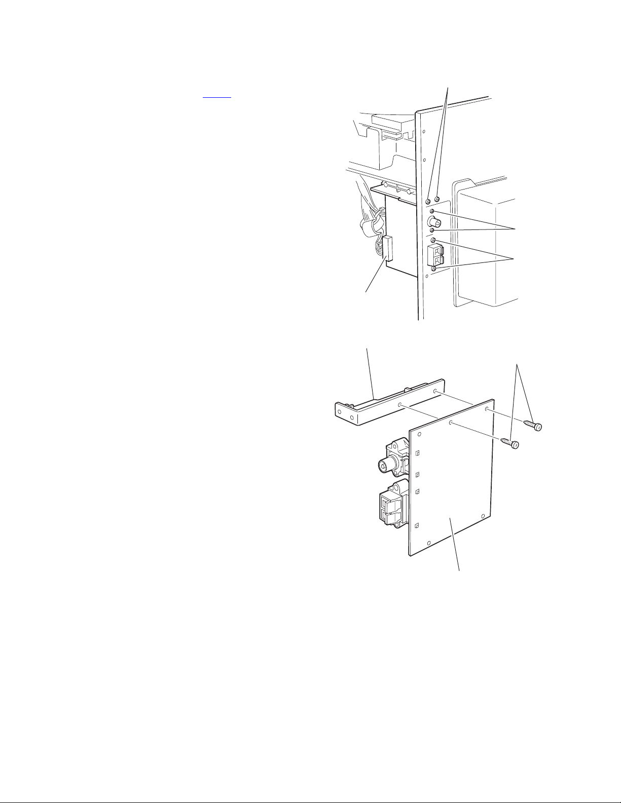
3.1.6 Removing the speaker terminal board
(See Fig.19, 20)
• Prior to performing the following procedure, remove the top
cover / side cover (R) and (L).
(1) Disconnect the wire from connector CN901
terminal board.
(2) From the back of the body, remove the two screws M at-
taching the speaker terminal board.
Reference:
You can remove the speaker terminal board without detaching
the CD changer mechanism unit and the rear panel.
on the speaker
Speaker terminal board
Rear panel
CN901
Fig.19
Rear cover
M
Rear panel
Fig.20
(No.MB284)1-13
Page 14
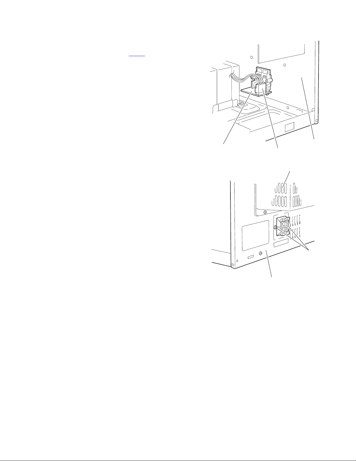
3.1.7 Removing the front panel assembly
(See Fig.21 to 24)
• Prior to performing the following procedure, remove the top
cover / side cover (R) and (L), the CD fitting / CD changer
mechanism unit.
(1) Disconnect the wire from connector CN861
board.
(2) Disconnect the earth wire from the base chassis on the bot-
tom of the right side of the body.
(3) From the bottom of the body, remove the two screws N at-
taching the front panel assembly.
(4) Release the two joints f on the side of the body and the joint
g on the bottom using a screwdriver, and remove the front
panel assembly forward.
on the power
Rear panel
Power board
CN861
Fig.21
Front panel assembly
1-14 (No.MB284)
f
Earth wire
Fig.22
Page 15
Front panel assembly
Fig.23
Front panel assembly
f
N
N
Fig.24
(No.MB284)1-15
Page 16
3.1.8 Removing the POWER switch board / CD switch board
(See Fig.25, 26)
• Prior to performing the following procedure, remove the front
panel assembly.
(1) Remove the two screws P and the three screws Q attach-
ing the bracket.
(2) Remove the screws R attaching the POWER switch board.
(3) Remove the screw T attaching the CD switch board.
P
Q
Front panel assembly
Fig.25
Bracket
P
CD switch boardPower switch board
RT
3.1.9 Removing the REC select switch board / PROGRAM select switch board
(See Fig.27)
• Prior to performing the following procedure, remove the front
panel assembly.
(1) Remove the three screws U attaching the REC select
switch board.
(2) Remove the three screws Y attaching the CD switch board.
Y
PROGRAM select
switch boaed
Front panel assembly
Fig.26
Front panel assembly
Y
Fig.27
U
U
REC select
switch boaed
1-16 (No.MB284)
Page 17
3.1.10 Removing the LCD board / STANDBY board
(See Fig.28, 29)
• Prior to performing the following procedure, remove the front
panel assembly.
(1) Remove the four screws A’ attaching the LCD board and
disconnect the wire from connector CN505
(2) Remove the two screws B’ attaching the STANDBY board.
.
Front panel assembly
A'
CN505
LCD board
Front panel assembly
A'
Fig.28
STANDBY board
B'
Fig.29
(No.MB284)1-17
Page 18
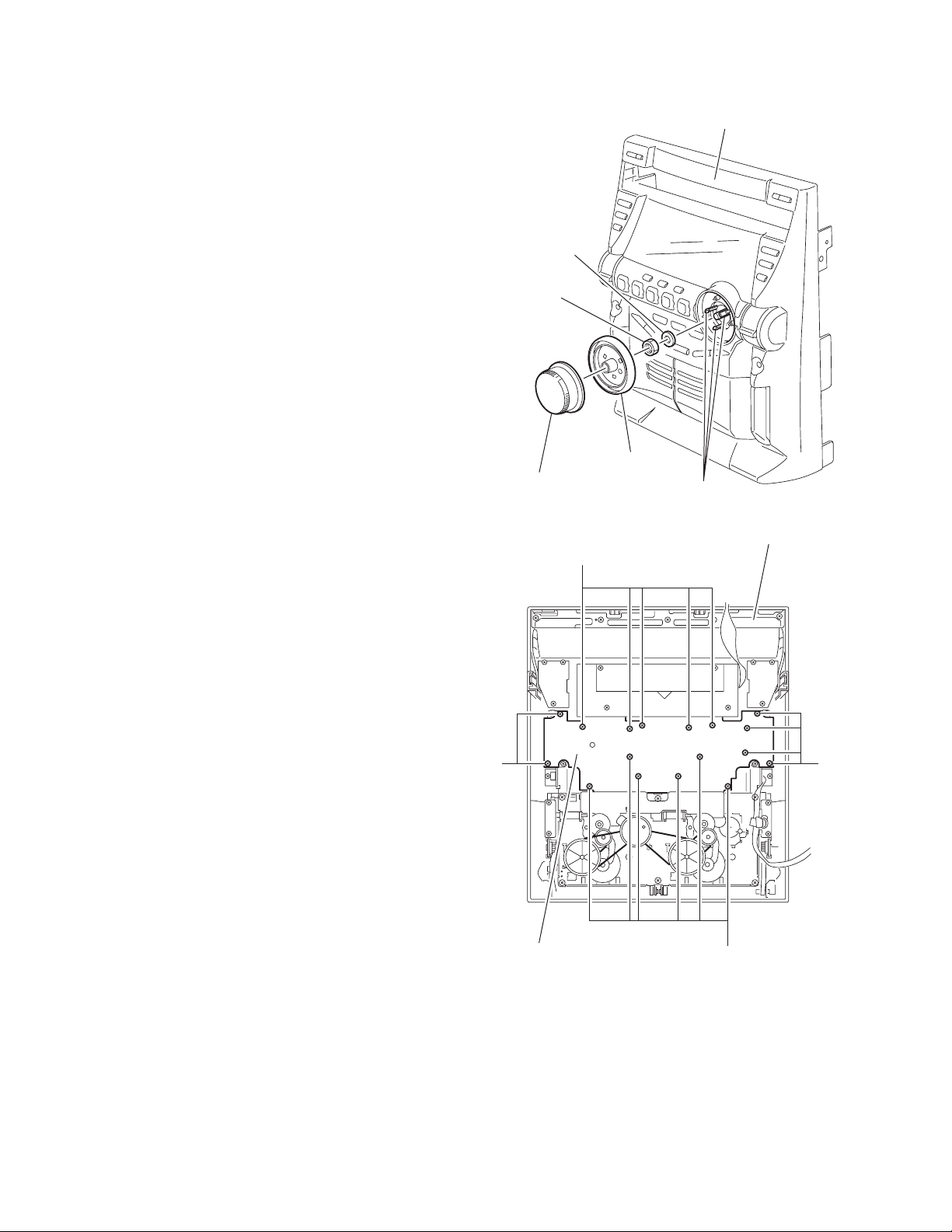
3.1.11 Removing the system board / headphone board / AUX board
(See Fig.30 to 34)
• Prior to performing the following procedure, remove the front
panel assembly.
(1) Pull out the volume knob on the front side of the front panel
assembly. Release the three tabs of the knob holder and
pull out the knob holder.
(2) Remove the nut and the washer from the volume shaft.
(3) From the back of the front panel assembly, remove the sev-
enteen screws D’ attaching the system board.
(4) Remove the screw E’ attaching the headphone board fit-
ting plate and pull out the headphone board.
(5) Remove the screw F’ attaching the AUX board fitting plate
and pull out the AUX board.
Washer
Nut
Volume knob
Front panel assembly
Knob holder
Ta b
Fig.30
Front panel assembly
D'
1-18 (No.MB284)
D'
System board
D'
D'
Fig.31
Page 19
Front panel assembly
Cassette mechanism assembly
G'
Headphone board
Fig.32
Front panel assembly
E'
Fitting plate
Front panel assembly
G'
Fig.34
F'
Fitting plate
AUX board
Fig.33
(No.MB284)1-19
Page 20
3.1.12 Removing the cassette mechanism assembly
(See Fig.35)
• Prior to performing the following procedure, remove the front
panel assembly.
(1) Remove the six screws G’ attaching the cassette mecha-
nism assembly.
Rear cover
H' H'
H'
Rear panel
Fig.35
H'
1-20 (No.MB284)
Page 21
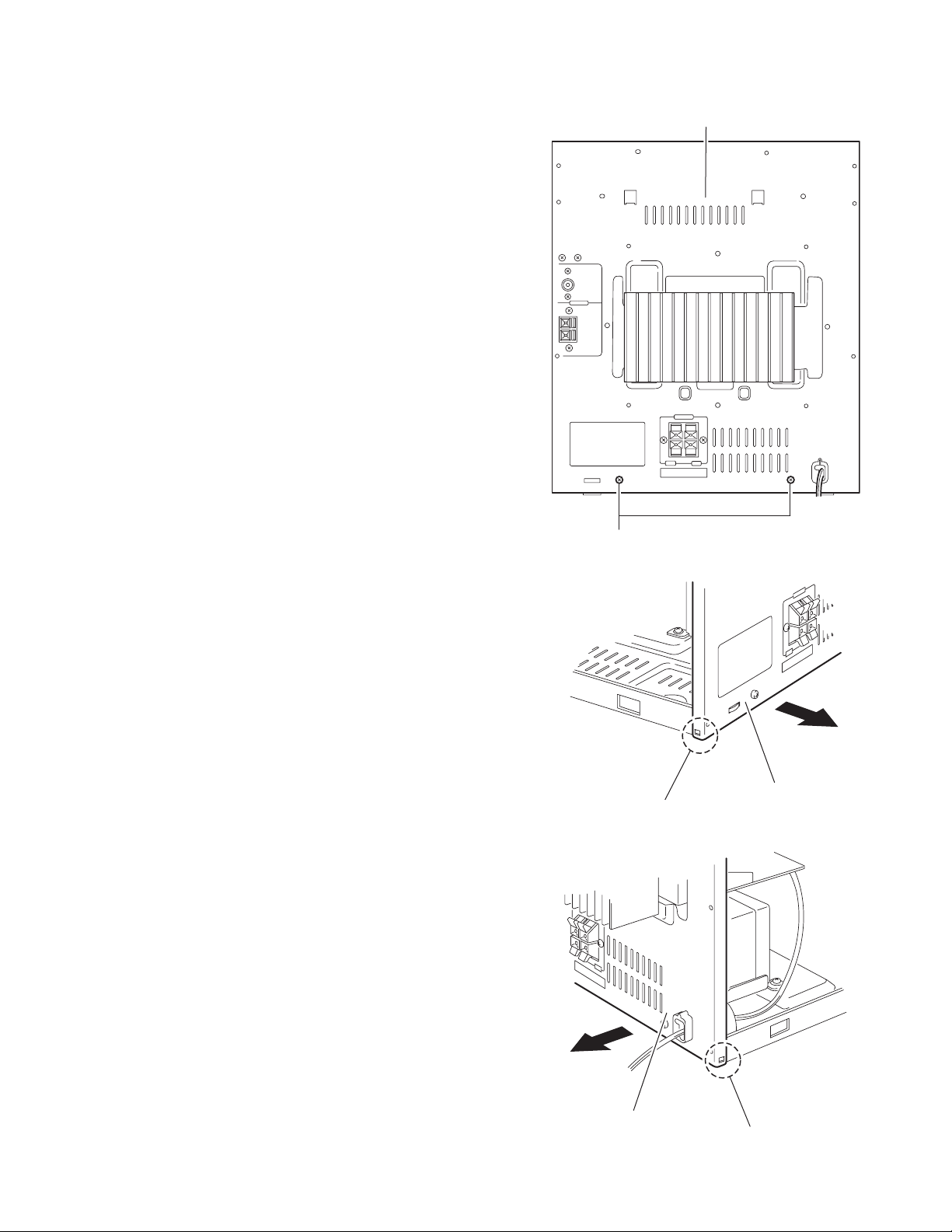
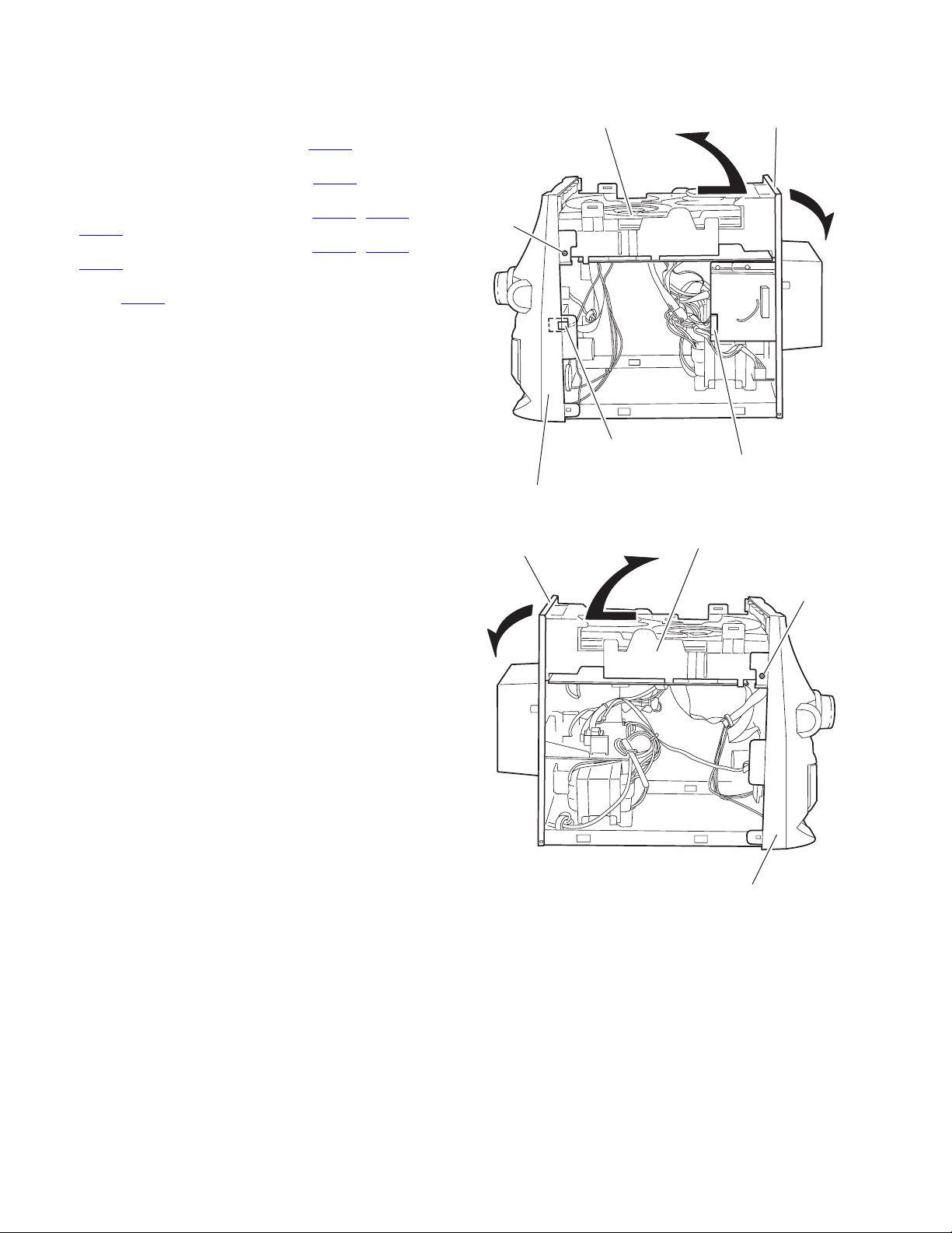
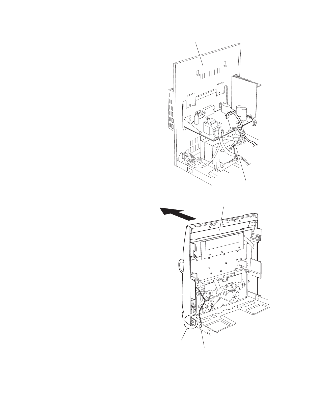
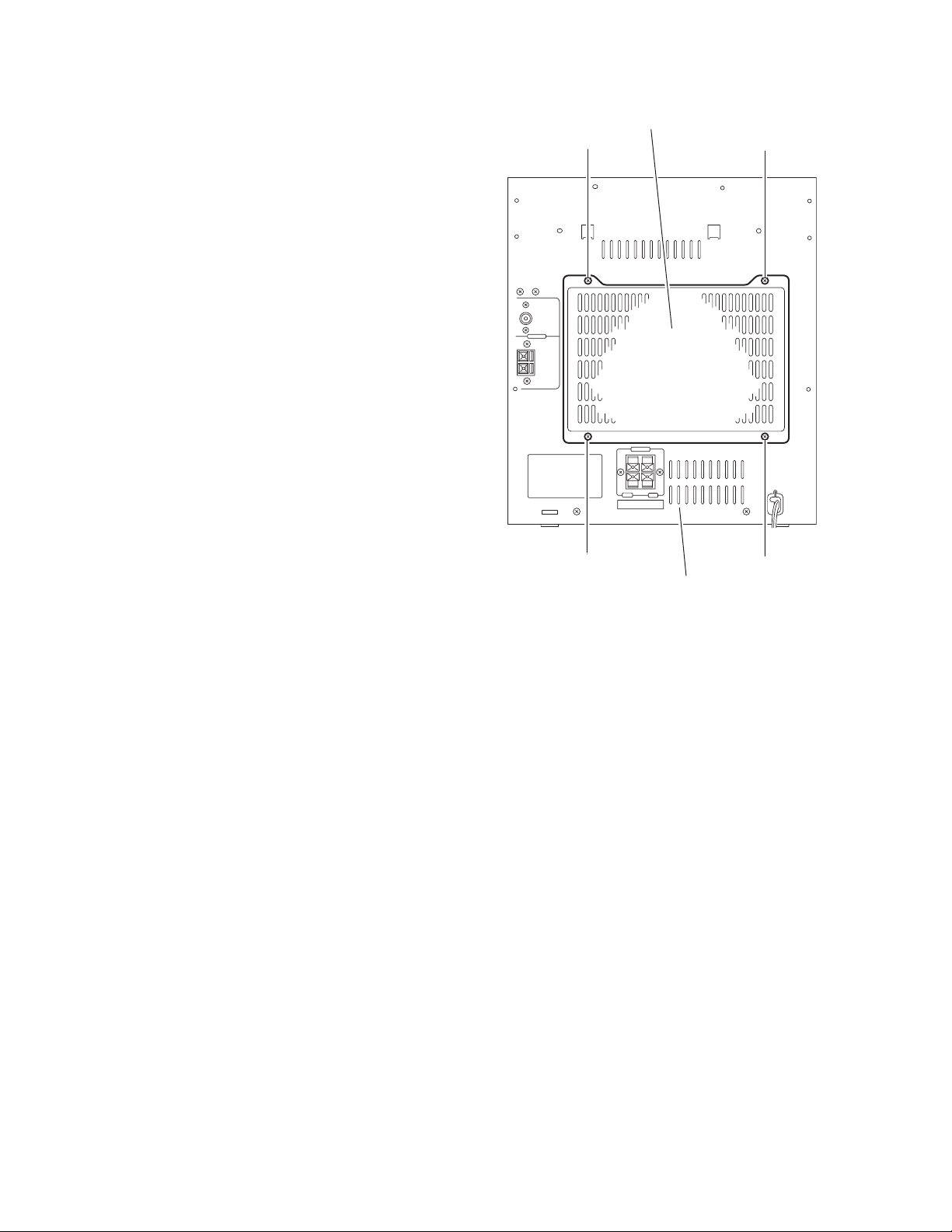
3.1.13 Removing the rear cover / rear panel
(See Fig.36 to 38)
• Prior to performing the following procedure, remove the top
cover / side cover (R) and (L), the CD fitting / CD changer
mechanism unit.
(1) From the back of the body, remove the four screws H’ at-
taching the rear cover.
(2) From the back of the body, remove the two screws J’ at-
taching the rear panel.
(3) Release the two joints h on the bottom of the right and left
sides of the rear panel, and remove the rear panel. The
rear panel comes off with the power board and the heat
sink.
Rear panel
J'
Fig.36
Rear panel
h
Fig.37
Raer panel
h
Fig.38
(No.MB284)1-21
Page 22
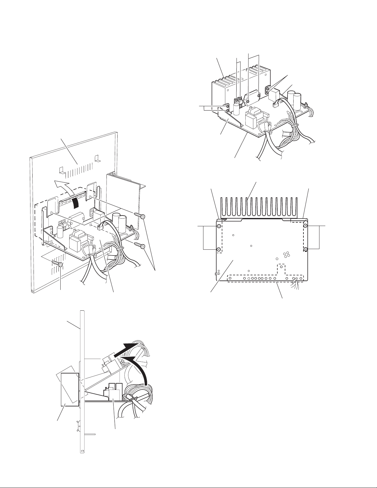
3.1.14 Removing the heat sink / power board
(See Fig.39 to 42)
• Prior to performing the following procedure, remove the top
cover / side cover (R) and (L), the CD fitting / CD changer
mechanism unit, the rear cover / rear panel.
(1) From the inner side of the rear panel, remove the four
screws K’ attaching the heat sink. Move the heat sink in the
direction of the arrow along the notch of rear panel and remove it with the heat sink and the power board forward.
(2) Remove the four screws M’ and the four screws N’ attach-
ing the board bracket (R) and (L).
(3) Remove the two screws P’ and the two screws Q’ attaching
the power board.
(4) If necessary, unsolder the power cord and the wire extend-
ing from the power transformer assembly.
Raer panel
P'
Heat sink
Q'
M'
Board bracket (R)
M'
Board bracket (L)
Power board
Fig.41
Board bracket (R) Board bracket (L)
Heat sink
K'
Raer panel
Fig.39
Power board
N' N'
K'
Power board
Soldered parts
Fig.42
Heat sink
1-22 (No.MB284)
Power board
Fig.40
Page 23

3.1.15 Removing the power transformer assembly
(See Fig.43)
• Prior to performing the following procedure, remove the top
cover / side cover (R) and (L), the CD fitting / CD changer
mechanism unit and the rear cover / rear panel.
(1) Move the cord stopper in the direction of the arrow and dis-
connect the power cord.
(2) Remove the four screws R’ attaching the power transform-
er assembly.
If necessary, unsolder each wire.
Power transformer
R'
R'
Fig.43
(No.MB284)1-23
Page 24

3.1.16 Removing the main board
(See Fig.44 to 46)
• Prior to performing the following procedure, remove the top
cover / side cover (R) and (L), the CD fitting / CD changer
mechanism unit.
Caution:
Before disconnecting the card wire from the CD pickup board
and connector CN401
the short-circuit point on the CD pickup board. If you do not follow this instruction, the pick up may be damaged.
(1) From the bottom of the CD changer mechanism unit, re-
move the two screws T’ and the four screws U’ attaching
the main board.
(2) Disconnect the wire from connector on the main board.
(3) Move the main board in the direction of the arrow as show
in Fig.45, disconnect the wire from connector on the motor
board in the inner part of the main board.
(4) Move the main board turning in the direction of the arrow
ash shown in Fig.45.
(5) Solder the short-circuit point on the CD pickup board and
disconnect the wire from the CD pickup board.
Caution:
When reattaching the main board, make sure to connect the
card wire to connector CN401
pickup board before unsoldering the short-circuit point.
CD changer mechanism unit
on the main board, make sure to solder
on the main board and to the CD
Main board
Main board
CD changer
mechanism unit
CW3
Motor board
CD pickup board
Short-circuit point
Fig.45
Card wire
T'
T'
U'U'
Short-circuit point
Fig.46
Connector
Fig.44
1-24 (No.MB284)
Page 25

3.2 Speaker
3.2.1 Removing the front cabinet
(See Fig.1 to 3)
Caution:
When performing the following procedure, apply the cloth to
the product for preventing it from damage.
(1) Put the screwdriver into the two notch a at the bottom of the
speaker, and remove the front panel assembly while pulling out the six bosses on the inner side of the front panel
assembly forward.
Caution:
The six bosses are attached with bond. Apply the cloth
to the product for protect from damage, and pull out each
boss carefully.
(2) Disconnect the two wires of the main speaker terminal from
the back of the front panel assembly.
(3) Disconnect the two wires of the sub speaker terminal from
the back of the front panel assembly.
aa
Boss
Boss
Fig.1
Front panel assembly
Sub speaker terminal
Boss
Fig.2
Main speaker terminalh
Fig.3
(No.MB284)1-25
Page 26

3.2.2 Removing the main speaker / sub speaker
A
(See Fig.4)
• Prior to performing the following procedure, remove the front
cabinet.
(1) Remove the four screws A attaching the main speaker.
(2) Remove the two screws B attaching the sub speaker.
Sub speaker
B
Main speaker
Fig.4
A
1-26 (No.MB284)
Page 27

SECTION 4
ADJUSTMENT
4.1 Measurement Instruments Required for Adjustment
(1) AM signal generator
(2) FM signal generator
(3) Intermadiate frequency sweep generator
(4) FM stereo signal generator
(5) Low-frequency oscillator
(oscillation frequency 50Hz-20kHz, 0dB output with 600 Ω impedance)
(6) Attenuator (600 Ω impedance)
(7) Electrinic voltmeter
(8) Distortion meter
(9) Wow & Flutter meter
(10) Frequency counter meter
(11) Test tape
VT712 : for Tape speed and wow flutter
VT724 : for reference level
VT703L : for head azimuth adjustment
Blank tape for recording
4.2 Measurement conditons
Radio section
FM 1 kHz, 22.5 kHz deviation
FM STEREO : 1 kHz, 67.5 kHz deviation pilot signal 7.5 kHz
AM : 1 kHz, 30 % modulation
Reference output :Headphone output (0.15V) 32 Ω
Speaker output 1W (2.5V) 6 Ω
Cassette amp section : 1 kHz
Reference output :Headphone output (0.15V) 32 Ω
Speaker output 1 W (2.5V) 6 Ω
Standard mode of function knob:Press TAPE knob of select TAPE mode
CD section
CD test disc : CTS-1000
(No.MB284)1-27
Page 28

4.3 Cassette amp section
Item Measuring condition Check and adjustment procedure Standard value Adjusting part
Head azimuth
adjustment
Tape speed and
wow/flutter check
and adjustment
Bias frequency
chek
Rec anf PB
frequency
response
adjustment
Test tape : VT703L
Signal output terminal :
SPK out
(with 6 ohm load)
Test tap : VT712
Signal output terminal :
SPK out
(with 6 ohm load)
Test tape : B
Signal output terminal :
Cassette REC/Play
head
Test tape : Brank tape
Signal input :
CD 1 kHz -20 dBs
Signal output terminal :
SPK out
(with 6 ohm load)
1. Playback the test tape VT703L.
2. Adjust the head azimuth adjusting screw so
that the phase difference between the R and
L channels is minimized at an output level
that is within (20dB of the maximum output
level. After this adjustment. Lock the head
azimuth adjusting screw with screw sealant
to cover more than a half of the screw head.
3. When the head azimuth is maladjusting
correct it with the head azimuth adjusting
screw.
1. Playback the test tape VT712 by the end
portion.
2. Connect a frequency counter and check that
it reads between 2940 and 3090 Hz. If not,
adjust the frequency with the motor
semifixed resistor.
3. Check that the wow/flutter is within 0.35%
(unweigthed).
Set the Tuner or CD function and with TAPE
to record check to see if the frequency at the
measuring point REC-IF is 85 kHz if not adjust
T100 until the frequency counter indicates
85 kHz+1kHz-1kHz.
Record the reference CD 1 kHz signal and 10
kHz signal alternately repeatedly. While playing
back the recorded signal of the 1 kHz signal
doffer from that of the 10 kHz signal by within
(0+3dB-6dB).
Output level :
Within (2 dB of
Maximum output
level.
*Phase difference
R and L channels :
Minimum
2940 to 3090 Hz
within 0.35%
(unweighted)
Level difference for
1 kHz signal :
within (0+3dB-6dB)
Level difference for
1 kHz signal :
within (0+3dB-6dB)
Head azimuth
adjusting screw
(To be use only
after head
replacement)
Tape speed
Motor semifixed
resistor
Check only
4.4 Tuner section (B/EV version)
Item Measuring condition Check and adjustment procedure Standard value Adjusting part
AM IF adjustment
AM tracking
adjustment
FM tracking
Signal input :
Loop antenna
Signal output :
IC602 pin 16ޓ62
Signal input :
Loop antenna
signal output :
H.phone out
(with 32 ohm load)
Signal input :
Analog antenna
FM ANT
Fm GND
signal output :
H.phone out
(with 32 ohm load)
1. Set the intermediate frequency sweep
generator to AM 450 kHz.
2. Adjust IFT601 for maximum and center
output
1. Set the TUNER at 531 kHz adjust IFT605
until the test point TP4 voltage at 1.3V+/-0.1V.
2. Set the TUNER at 1710 kHz, check the test
point TP4 voltage at 7.0 to 8.0 V.
3. Set the TUNER and S/G at 600 kHz, adjust
IFT606 for maximum output.
4. Set the TUNER and S/G at 1500 kHz, adjust
the VC606 for maximum output.
5. Repeat the avobe step 3 and 4.
1. Set the TUNER at 87.5MHz adjust L604 until
the point TP5 voltage at 1.5V+/-0.1V.
2. Set the TUNER at 108MHz, check the point
TP5 voltage at 7.2-8.0V.
3. Set the TUNER and S/G at 90.1MHz, adjust
L605 for amximum output.
4. Set the TUNER and S/G at 106.1MHz, adjust
the VC604 for maximum output.
IFT601
IFT605
IFT606
VC606
L604
L605
VC604
1-28 (No.MB284)
Page 29

4.5 Location of adjusting parts
Cassette mechanism section
(caution) For adjusting any head, be sure to use a screw driver degaussed.
max
Head
Adjustment
Cassette motor
-
+
Head output signal
Main board
Tuner section
Azimuth adjustment screw
Tape speed adj.
Main board
(BIAS FREQUENCY)
T100
REC-F
REC-G
FM ANT
VC606
AM RF
IFT606
AM RF
IFT605
AM OSC
L604
FM OSC
AM ANT
L605
FM ANT
FM
IFT601
VC604
AM IF
CF604
IFT602
(No.MB284)1-29
Page 30

4.6 Flow of functional operation until TOC read
Power ON
Slider turns REST
SW ON.
Laser ON
Focus start
FOK
Turn on focus
servo
Confirm that the voltage at the pin5 of CN402
is 'H' 'L' 'H'.
Check that the voltage at the pin7(CD) of CN401
is 1.8V.
Caution. Before connecting a measuring instrument to
the measuring point, turn the power of the
main unit to OFF.
After performing a measurement and before
disconnecting the measuring instrument,
again turn the power of the main unit to OFF.
(If a measuring instrument is disconnected
while an electric current is being output ot the
main unit, the pickup of the main unit will be
damaged.)
Disc spinning
Radial_error
scaling
PLL Lock
Turn on radial
servo
Read TOC
Check that the voltage at the pin1 and pin2 of
CN402 is 0.65V.
Confirm the eye-pattern at the 'RFO' test point.
1-30 (No.MB284)
Page 31

SECTION 5
TROUBLESHOOTING
This service manual does not describe TROUBLESHOOTING.
(No.MB284)1-31
Page 32

Victor Company of Japan, Limited
AV & MULTIMEDIA COMPANY AUDIO/VIDEO SYSTEMS CATEGORY 10-1,1chome,Ohwatari-machi,Maebashi-city,371-8543,Japan
(No.MB284)
Printed in Japan
WPC
Page 33

SCHEMATIC DIAGRAMS
COMPACT COMPONENT SYSTEM
MX-KB2,MX-KB15
CD-ROM No.SML200408
Contents
Wiring diagram
Block diagram
Standard schematic diagrams
Printed circuit boards
COPYRIGHT 2004 Victor Company of Japan, Limited.
Area suffix
C ------------------------- Canada
2-2
2-4
2-6
2-18 to 22
No.MB287SCH
2004/8
Page 34

In regard with component parts appearing on the silk-screen printed side (parts side) of
the PWB diagrams, the parts that are printed over with black such as the resistor ( ),
diode ( ) and ICP ( ) or identified by the " " mark nearby are critical for safety.
Page 35

< MEMO >
2-1
Page 36

C
8
0
2
Wiring diagram
AC CORD P/N.: 30-00300-00L
(AC 120V - 60 Hz)
FM ANT
Tuner board
P/N:11-01002-03
P/N:20-61030-00
3 PIN UL2547#30 P=2 L=360 mm
A PLAY HEADER
LOGIC DECK CONTROL BUS
AUX INPUT
SJ500
CN504
AUX input board
J601J602
AM ANT
TU-R
AGND
TU-L
+12V
+5.6V
DGND
STEREO
CD-EN
PLL-DAT
PLL-CLK
PLL-PER
RDS-CLK
RDS-DAT
CN601
P/N:20-61070-00 7 PIN UL2854#30 P=2L=360 mm
LOGIC DECK
B R/P HEADER
P/N:25-61260-80 13 PIN UL2896 P=1.25 L=260 mm
P/N:11-01002-05
Transformer
P/N:15-01002-00
P/N:20-61030-02
3P UL547#30 P=2 L=300 mm
P/N:20-61133-01
13P UL2547+2651 P=2 L=370 mm
CN202
CN101
L-IN
AGND
R-IN
R.CHR.CH+
GND
L.CH+
L.CHGND
E-S
CN103
GND
NIL
SOL-B
B-M-SW
B-T-SW
PHO-B
REC-SW
T-MOTOR
A-T-SW
GND
PHO-A
SOL-A
A-M-SW
TU-R
AGND
P/N:20-61073-11
7P UL2547+2651 P=2 L=250 mm
TU-L
+12V
+5.6V
DGND
STEREO
CD-EN
PLL-DAT
PLL-CLK
PLL-PER
RDS-CLK
RDS-DAT
CN205
CN201
AC7
CN803
ECO
HP-M
MUTE
STBY
L-OUT
GND
R-OUT
AC6
P/N:2
2 PIN
AC9
CN110
L-IN
R-IN
GND
Main board
P/N:11-01002-00
AC2
AC1
-27V
KEY2
JOG-B
JOG-A
IR-IN
D-STB
D-CLK
D-DAT
+5.6V
CGND
CN20
OL-DET
OL-PROT
KEY1
CN207
2-2
P/N:25-83100-02
2PIN UL2651#28 P=2 L=100 mm
Display & Key
CN511
CN510
Top left key
P/N:11-01002-12
Left key
P/N:11-01002-10
2PIN UL2468#26
P/N:25-94060-80
CN509
CN503
CN505
IR1
GND
IR3
LED+
P/N:20-41130-00
13 PIN UL2651#28 P=2 L=
CN500
AC1
AC2
-27V
IR-IN
KEY2
KEY1
+5.6V
CGND
D-STB
D-CLK
D-DAT
JOG-A
JOG-B
Main key
P/N:11-01002-09
P/N:20-41040-00
4 PIN UL2651#28 P=2 L=50 mm
Page 37

AC1
P/N:20
61073
11
-
-
7P UL2547+2651 P=2 L=250 mm
CN803
AC7
AC6
CN802
AC9
Power board
P/N:11-01002-16
P/N:20-42110-00
11PIN P=2.5 L=250 mm
AC5
AC10
AC11
AC8
AC3
CN861
CN801
CN804
GND1
P/N:20-45041-80
4P UL1007#20 L=250 mm
CN901
P/N:20-41051-37
5P UL2651#28 L=500 mm
Speaker board
P/N:11-01002-06
CN902
Headphone board
P/N:11-01002-05
R
L
CN201
ECO
CN205
110
Main board
P/N:11-01002-00
HP-M
MUTE
STBY
L-OUT
GND
R-OUT
OL-DET
OL-PROT
+9V
+5V
AC1
AC2
-27V
+12V
+5.6V
AGND
DGND
DGND
CGND
P/N:20-41020-00
2 PIN UL2651#28 P=2 L=250 mm
P/N:20-51061-20
6 PIN UL1571#30 P=2 L=100 mm
CN208
FM-
SLT
DM-
FM+
DM+
GND
CN402
16.V-CEN
15. COM
14. E
13. D
12. A
11. B
10. C
8. GND
7. LD
6. VR
5. PD
4. F+
3. T+
CD DECK
P/N:25-61135-80
CN401
16 P Ul2896 P=1 L=135 mm
PICK UP
3CD MODULE
9. F
2. T-
1. F-
CN204
SW2
GND
SW1
RL-
RL+
+5V
EMT
CATH
MO-
CN206
AC2
CGND
-27V
KEY1
KEY2
JOG-B
JOG-A
IR-IN
D-STB
D-CLK
D-DAT
+5.6V
CN207
RL-
+5V
RL+
MO-
SW1
EMT
SW2
MO+
GND
CATH
P/N:20-41101-24
10 PIN UL2651#28 P=2 L=250 mm
Motor board
MO+
CW3
P/N:20-41130-00
13 PIN UL2651#28 P=2 L=250 mm
CN500
AC1
AC2
-27V
IR-IN
KEY2
KEY1
+5.6V
CGND
D-STB
D-CLK
D-DAT
JOG-A
JOG-B
Main key
P/N:11-01002-09
P/N:20-41040-00
4 PIN UL2651#28 P=2 L=50 mm
Display board
P/N:11-01002-07
P/N:25-83050-05
5 PIN UL2651#28 P=2 L=50 mm
CN501
KEY1
KEY2
CGND
JOG-A
JOG-B
CGND
KEY1
KEY2
CN502
JOG-A
JOG-B
CN506
P/N:25-94060-80
2 PIN UL2468#26
Top light key
P/N:11-01002-13
Right key board
P/N:11-01002-11
CN512
CN508
Remote receive
P/N:11-01002-14
CN514
CN513
P/N:25-83100-02
2P UL2651#28 P=2 l-100 mm
2-3
Page 38

Block diagram
0
O
5
d
t
e
Key board section
CD2
S501
VFD CONTROL / DRIVER
SC6122
REMOTE RECEIVER
ENCODE VOLUME
45
EN500
321
+9V
U101
TA8189
4CH Pre+Rec
AMP with ALC
BIAS OSC
R/P SWITCH CIRCUIT
LOGIC DECK-TP
IC602
TA2149BFN
IF
IC600
TC9257 PLL
JOG-A
JOG-B
H CASS A
L CASS B
REC-E
H-PLAY
L-REC
+9V
VFD
KEY2
KEY1
U500 SC6311
KEY SCAN
CLK
DATA
CPU
87EP26F-4K76
STB
REC SIGNAL
OUTPUT
Filament
AC3.3V
+5V
STANDBY LED
GVSW
CDR-W GAIN
CONTROL
+5V
VCC
DATA AND CONTROL
U406
TC74HC14
STB
DATA
CK
L CH
R CH
+5V
R503
680R
LED500
BUS
L CH
R CH
SDA
REQ
SCL
L CH
R CH
U201 TC9422F
SYSTEM E.VOLUME
(Tone control input
selector Main volume)
SYS_MUTE
PICKUP
EDA
U402 TA2153
RF AMPLIFIER
RF
DIGITAL SERVO
1 BIT D/A CONVERTER
U404 TC94A02F
CD ROM DECODE
MP3 DECODE
D/A CONVERTER
D803
IN4001
F
B
C
LD
FEO
RFCT
RFPP
U401 TC9462
+9V
R832
10k
R83110k
Q812
8050
LIMIT SW
Q813
8050
F-
+5V
FOO
TRO
DMO
FMO
ADDRESS BUS
DATA BUS
VDD 3V
VDOT 3.3V
+VC
IC801 STK402-050
LOW LOGIC DETECT
PROTECT ENABLE
Q860,Q861,Q864,Q865
DETECT
OVERLOAD
DIGITAL SERV
-VC
ENABLE
PROTECT
When use hea
the control vol
T-
T+
F+
U403 TA2
U405 SRAM
128k x 8 (1
logic low l
2-4
AUX INPUT
L CH
R CH
Page 39

+9V
0
2
n
TO 3CD DECK
T+
F+
403 TA2092N
L SERVO DRIVER
5 SRAM (SDJ)
8k x 8 (15ns)
+9V
VDD 3.3V
FM-
FM+
123456
CN402
123456
TO CD DECK
DM-
DM+
+VC
-VC
SLT
D849-D852
R241
10k
M-
M+
R242
IN2
U203 TA7219S
BRIDGE DRIVER
IN1
10k
EMIT
R233
10k
ML+
IN1
U202 TA7219S
BRIDGE DRIVER
IN2
ML-
R232
10k
3CD CHANGER DRIVER SECTION
SW1
SW2
CN204
1
2
3
4
5
6
7
8
9
10
AC PLUG
MO+
MO-
CATH
EMIT
+5V
RL+
RL-
SW1
GND
SW2
+12V
+9V
HEADPHONE
CE803
100uP/50V
Q862
8550
+12V
D806-D809
L7809CV
Q803
D845
IN4001
U803
L7806CV
AC7
AC10
AC12
AC11
AC8
AC9
AC5
T802
T06910A
1
7
86543211
!
TRANSFORMER
10
AC3
AC4
9
!
F804
T2.0A/250V
R862
10k
use headphone
ontrol voltage is
gic low level
R877
22k
Q867
8050
GRID VOLTAGE -27V
AC 3.3V
FILAMENT VOLTAGE
+6V TO CPU
2-5
Page 40

PRE_AMP
AMP
STK402-050
Standard schematic diagrams
Primary / Power amp section
2-6
PROTECT CIRCUIT
!
Page 41

!
!
!
!
!
!
!
2-7
Page 42

Main section
80
81
82
83
3835-AIN
84
85
86
87
88
89
90
91
92
93
94
95
96
PLL-DAT
97
PLL-CLK
98
PLL-PER
99
VDD
100
Vss
123456789
79
78
77
76
75
74
73
72
71
70
69
68
67
66
65
64
63
62
61
60
59
58
57
56
55
54
53
52
51
T-A/B
A-PHP
B-CUT
3835-B
3835-A
3835-C
XOUT
OL-DET
PRO-EN
MP3-SCLK
U300
87EP26F-4K76
XIN
REST
XT-OUT
XT-IN
TEST
F-SHIFT
REMOTE
MUTE
VFD-CLK
VFD-FTB
VFD-DAT
ESS-CLK
101112131415161718192021222324252627282930
A-PHO
B-T-SW
A-M-SW
T-MOTO
MP3-REQ
MP3-SDAT
ESS-DAT
ESS-STB
REC-EN
SOL-A
SOL-B
ECO
VOL-STB
POWER
MR+
VDD
50
JOB-B
JOB-A
B-PHO
VOL-DAT
B-M-SW
VOL-CLK
REC-SW
RDS-CLK
REC-SW
D-SEN
Vss
49
BOOT
48
VREF
47
KEY1
46
KEY2
45
KEY3
44
POW-D
43
STEREO
42
RDS-DAT
41
SW2
40
SW1
39
STL
38
MD+
37
MD-
36
DUCK3
35
DUCK2
34
DUCK1
33
BUCK0
32
DUCK
31
CEE
MR-
CD.RW
CD.RES
2-8
NF2
ME/02
PRE/02
U101 TA8189N
NF1
ME/01
PRE/01
19181716151413
A/B
DET
VCC
MIX/0
AGND
M/N
2423222120
CH2/A
CH2/B
CH1/A
CH1/B
123456789
REC/01
REC/02
RNF
REC/I1
CNF
REC/I2
101112
ALC
GND
123
4
Page 43

123456789
101112
13
2-9
Page 44

Display / Key control section
3CD 08 00:08
FROM MAIN PCB
MAIN KEY BOARD
STANDBY LED
DISPLAY BOARD
2-10
Page 45

ENCODER VOLUME
KEY BOARD
RIGHT KEY BOARD
LEFT KEY BOARD
TOP RIGHT KEY BOARD
TOP LEFT KEY BOARD
2-11
Page 46

TO MCU
CD section
2-12
U401
TC9462F
Page 47

TO
CD
DECK
TO PICK UP
2-13
Page 48

MP3 section
SDA
REQ
SCL
TO MCU
646362616059585756555453525150
XI
XO
VSSX
1
RESET
2
MIMD
3
AD0
4
AD1
5
SDA
6
SCL
7
AD2
8
VDDT
9
SD0
10
AD3
11
AD4
12
SDIO
13
BCKIA
14
LRCKIA
15
AD5
16
CE
DE
VDD
171819202122232425262728293031
STANDBY
VDDX
VSS
CKO
VDDP
VSSL
VRALLOVDAL
PDO
VCOI
U404
TC94A02F
VSSP
VDARROVRAR
49
ID6
IO7
IO5
IO4
IO3
CKS
AD12
IO2
48
VSS
47
IO1
46
IO0
45
AD15
44
AD16
43
WR
42
AD14
41
AD13
40
VSS
39
REQ
38
AD6
37
AD7
36
AD8
35
VDDT
34
AD9
33
AD10
AD11
32
VSSR
VDD
TESTP
2-14
Page 49

1645141312111098765432
IO3
IO2
IO1
AD0
AD1
AD2
AD3
AD4
AD5
GND
CE1
IO5
48
47
1
46
0
45
5
44
6
IO4
171819202122232425262728293031
AD10OEAD11
IO6
IO7
IO8
AD6
AD9
AD8
AD7
AD12
AD13WECE2
AD14
AD16
AD15
1
NC
VDD
32
43
42
4
41
3
40
39
38
6
37
7
36
8
35
34
9
33
0
2-15
Page 50

P
Tuner section
RGND FM-RF LOW
CUT
MIX
VCC AM-IF FM-IF GND AGC Q
OUT
IC602 TA2149BFN
M
DET-OUTIF-REQSTDSC-OUTAM-OSCFM-OSCAM-RFRF-VCCFM-RF/O
2-16
Page 51

AM-IF FM-IF GND AGC QUAD R/OUT L/OUT
2 TA2149BFN
LPF2LPF1MPX-INDET-OUTIF-REQSTDSC-OUT
TU_R
AGND
TU_L
+12V
+5.6V
DGND
ST
CD_EN
PLL_DATA
PLL_CLK
PLL_PER
NOTES:
ALL OF THE VOLUME OF THE COMPONENT VOLTAGE
TESTED AT THE FM MODE. NO SIGNAL INPUT STATUS
2-17
Page 52

Printed circuit boards
Main board
(forward side)
2-18
Page 53

(reverse side)
2-19
Page 54

Display board
(forward side)
(reverse side)
2-20
Page 55

Tuner board
(forward side)
(reverse side)
2-21
Page 56

Trans board
(forward side)
!
!
!
!
!
!
(reverse side)
2-22
Page 57

< MEMO >
2-23
Page 58

Victor Company of Japan, Limited
AV & MULTIMEDIA COMPANY AUDIO/VIDEO SYSTEMS CATEGORY 10-1,1chome,Ohwatari-machi,Maebashi-city,371-8543,Japan
(No.MB287SCH)
Printed in Japan
WPC
Page 59

PARTS LIST
[ MX-KB2 ]
[ MX-KB1 ]
* All printed circuit boards and its assemblies are not available as service parts.
Area suffix
UW ---------- Brazil,Mexico,Peru
MB284
- Contents -
Exploded view of general assembly and parts list (Block No.M1)
Electrical parts list (Block No.01~04)
Packing materials and accessories parts list (Block No.M3)
3- 2
3- 6
3-14
3-1
Page 60

Exploded view of general assembly and parts list
K
0
Block No.
76
M
M
1
M
41
12
13
Main board
67
35
34
3
6
47
1
68
70
63
14
67
11
33
38
58
44
58
63
68
33
44
32
38
25
79
32
14
58
45
80
78
8
77
10
59
18
65
28
29
5
24
30
23
31
27
22
20
26
21
19
68
46
6
Main
59
9
3-2
42
43
17
72
39
4
64
64
72
7
2
48
Page 61

15
59
0
59
57
Key board
36
59
57
50
60
61
71
57
56
Display board
57
60
64
57
59
59
15
61
F804
90
F803
89
F802
88
F801
87
64
37
51
49
64
55
83
55
91
85
86
66
75
54
66
84
65
68
65
63
62
57
64
52
62
64
64
64
73
69
53
Power board
62
65
16
65
64
74
64
40
3-3
Page 62

General Assembly
Symbol No. Part No. Part Name Description Local
1 OW43-01001-03 CASS LENS L
2 OW43-01001-04 CASS LENS R
3 OW43-01001-02 DISPLAY WINDOW KB1
3 OW43-01001-05 DISPLAY WINDOW KB2
4 OW48-01001-00 VOLUME RING
5 OW48-01001-01 KNOB BRACKET FUNCTION
6 OW48-01001-02 CASS BRACKET L
7 OW48-01001-03 CASS BRACKET R
8 OW48-01001-04 BASS KNOB LEVER
9 OW48-01001-05 SOUND KNOB LEVER
10 OW48-01001-06 VFD BRACKET
11 OW48-01001-07 REMOTE BRACKET
12 OW48-01001-08 PCB BRACKET L MAIN
13 OW48-01001-09 PCB BRACKET R MAIN
14 OW48-01001-10 SUPPORT BLOCK (x2)
15 OW48-01001-11 SUPPORT WASHER (x2)
16 OW48-01001-12 PCB BRACKET TUNER
17 OW51-01001-00 VOLUME KNOB
18 OW53-01001-00 AUX KNOB
19 OW53-01001-01 OPEN CLOSE KNOB
20 OW53-01001-02 RECORD KNOB
21 OW53-01001-03 REPEAT KNOB
22 OW53-01001-04 CLOCK KNOB
23 OW53-01001-05 CD KNOB
24 OW53-01001-06 STOP KNOB
25 OW53-01001-07 BASS KNOB
26 OW53-01001-08 SOUND KNOB
27 OW53-01001-09 POWER KNOB
28 OW53-01001-11 FM/AM KNOB
29 OW53-01001-12 CD PLAY KNOB
30 OW53-01001-13 TAPE A KNOB
31 OW53-01001-14 TAPE B KNOB
32 OW55-00005-80 LATCH (x2)
33 OW55-00005-81 LATCH HOLDER (x2)
34 OW55-01001-00 JVC BADGE
35 OW60-01001-02 FRONT PANEL
36 OW60-01001-01 TOP CABINET
37 OW61-01001-00 HEATSINK COVER
38 OW63-00303-80 DAMPER GEAR for CASS DOOR(x2)
39 OW65-01001-00 SIDE PANEL L
40 OW65-01001-01 SIDE PANEL R
41 OW66-01001-00 3 CD DOOR
42 OW66-01001-01 CASS DOOR L
43 OW66-01001-02 CASS DOOR R
44 OW36-00005-80 CASS SPRING (x2)
45 OW36-01001-00 SPRING BASS KNOB
46 OW36-01001-01 SPRING SOUND KNOB
47 OW36-01001-02 SPRING CASS DOOR L
48 OW36-01001-03 SPRING CASS DOOR R
49 OW39-01001-01 BOTTOM
50 OW39-01001-03 SUPPORT PLATE for DISPLAY&KEY PCB
51 OW39-01001-04 HEAT SINK
52 OW39-01001-05 HEAT SINK BKT L
53 OW39-01001-06 HEAT SINK BKT R
54 OW39-01001-17 BACK PLATE KB1
54 OW39-01001-10 BACK PLATE KB2
55 OW40-84006-53 SCREW (x4)
56 OW40-92008-01 SCREW (x3)
57 OW40-92608-11 SCREW (x13)
58 OW40-92610-01 SCREW (x6)
59 OW40-92612-01 SCREW (x19)
60 OW40-92615-01 SCREW (x6)
61 OW40-92616-01 SCREW (x2)
62 OW40-93006-51 SCREW (x6)
63 OW40-93008-11 SCREW (x10)
64 OW40-93008-51 SCREW (x22)
65 OW40-93010-01 SCREW (x12)
66 OW40-93010-51 SCREW (x4)
67 OW40-93015-01 SCREW (x4)
68 OW40-93015-02 SCREW (x6)
69 OW40-93015-51 SCREW (x2)
70 OW43-01001-00 MIRROR SHEET
71 OW68-91002-00 SHIELD PAPER
72 OW81-01001-00 RUBBER FOOT (x2)
Block No. [M][1][M][M]
3-4
Page 63

Symbol No. Part No. Part Name Description Local
73 OW81-01001-01 MICA SHEET
74 OW81-01001-02 RUBBER FOOT (x2)
75 OW84-10002-80 STRAIN RELIEF
76 OW98-01001-00 CD CHANGER CMS-FR3BN
77 OW94-01002-00 CASSETTE MECHA CWM43FF44
78 OW91-01002-00 VFD DISPLAY
79 OW12-21235-80 HEADPHONE JACK EJ-3511-0202B
80 OW12-10035-12 PHONE JACK F3.5 ST-101
83 OW15-01002-05 POWER TRANS EI-76 KB1
83 OW15-01002-02 POWER TRANS EI-76 KB2
84 OW12-00006-81 SPK TERMINAL CJ-0007-040
85 OW16-60014-80 VOL SELECTOR
86 OW48-01001-14 BRACKET VOLTAGE SELECTOR
87 OW33-57402-02 FUSE F801 4A 250V
88 OW33-57402-02 FUSE F802 4A 250V
89 OW33-57202-03W FUSE F803 2A 250V
90 OW33-57402-02 FUSE F804 4A 250V
91 OW30-00300-01L AC CORD
3-5
Page 64

Electrical parts list
Main board
Block No. [0][1]
Symbol No.
U101 TA8189N IC OW03-08189-80
U201 TC9422 IC OW03-09422-80
U202 TA7291S IC OW03-07291-80
U203 TA7291S IC OW03-07291-80
U300 87EP26F-4K76 IC OW03-87261-80
U401 TC9462F IC OW03-09462-80
U402 TA2153FN IC OW03-02153-80
U403 TA2092N IC OW03-02092-80
U404 TC94A02F IC OW03-09402-80 KB2
U405 AS7C31024-15JC IC OW03-31024-80 KB2
U406 TC74HC14 IC OW03-07404-80 KB2
Q100 DTC314TS TRANSISTOR OW01-00314-20
Q101 DTC314TS TRANSISTOR OW01-00314-20
Q102 2SC945-P TRANSISTOR OW01-00945-80
Q103 2SC945-P TRANSISTOR OW01-00945-80
Q104 2SA733PNP TRANSISTOR OW01-00733-80
Q105 2SC945-P TRANSISTOR OW01-00945-80
Q106 2SC945-P TRANSISTOR OW01-00945-80
Q108 KSA928A-Y TRANSISTOR OW01-00928-80B
Q109 2SC945-P TRANSISTOR OW01-00945-80
Q110 KSA928A-Y TRANSISTOR OW01-00928-80B
Q111 2SC945-P TRANSISTOR OW01-00945-80
Q112 KSA928A-Y TRANSISTOR OW01-00928-80B
Q113 2SC945-P TRANSISTOR OW01-00945-80
Q115 2SA733PNP TRANSISTOR OW01-00733-80
Q116 DTC314TS TRANSISTOR OW01-00314-20
Q117 DTC314TS TRANSISTOR OW01-00314-20
Q118 DTC314TS TRANSISTOR OW01-00314-20
Q119 DTC314TS TRANSISTOR OW01-00314-20
Q120 DTC314TS TRANSISTOR OW01-00314-20
Q121 DTC314TS TRANSISTOR OW01-00314-20
Q122 2SA733PNP TRANSISTOR OW01-00733-80
Q123 2SC945-P TRANSISTOR OW01-00945-80
Q207 2SC945-P TRANSISTOR OW01-00945-80
Q208 KSA928A-Y TRANSISTOR OW01-00928-80B
Q209 2SC945-P TRANSISTOR OW01-00945-80
Q210 KSA928A-Y TRANSISTOR OW01-00928-80B
Q211 2SC945-P TRANSISTOR OW01-00945-80
Q212 2SC945-P TRANSISTOR OW01-00945-80
Q300 2SC945-P TRANSISTOR OW01-00945-80
Q302 2SC945-P TRANSISTOR OW01-00945-80
Q402 2SC945-P TRANSISTOR OW01-00945-80 KB1
Q403 2SC945-P TRANSISTOR OW01-00945-80 KB1
Q405 2SA733PNP TRANSISTOR OW01-00733-80
Q406 2SC945-P TRANSISTOR OW01-00945-80 KB2
Q407 2SC945-P TRANSISTOR OW01-00945-80 KB2
Q408 2SC945-P TRANSISTOR OW01-00945-80 KB2
Q409 8050D TRANSISTOR OW01-08050-81 KB2
Q410 8050D TRANSISTOR OW01-08050-81 KB2
Q411 8050D TRANSISTOR OW01-08050-81 KB2
D300 1N4148 DIODE OW02-04148-81
D301 1N4148 DIODE OW02-04148-81
D302 1N4148 DIODE OW02-04148-81
D303 1N4148 DIODE OW02-04148-81
D304 1N4148 DIODE OW02-04148-81
D305 1N4148 DIODE OW02-04148-81
D404 1N4001 DIODE OW02-04001-81
D405 1N4148 DIODE OW02-04148-81 KB1
D406 1N4001 DIODE OW02-04001-81
Z200 3.3V0.5W Z DIODE OW02-50033-80T
Z201 6.2V0.5W Z DIODE OW02-50062-80
Z306 10V0.5W Z DIODE OW02-50100-80
Z402 3.3V0.5W Z DIODE OW02-50033-80T KB2
Z403 3.3V0.5W Z DIODE OW02-50033-80T KB2
Z404 3.9V0.5W Z DIODE OW02-50039-81 KB2
C03 OW05-77102-10 C CAPACITOR Axial 1000pF
C04 OW05-77102-10 C CAPACITOR Axial 1000pF
C05 OW05-77102-10 C CAPACITOR Axial 1000pF
C06 OW05-77102-10 C CAPACITOR Axial 1000pF
Part No. Part Name Description Local
Symbol No.
C100 OW05-73561-00 C CAPACITOR 560pF
C101 OW05-73561-00 C CAPACITOR 560pF
C102 OW05-73221-00 C CAPACITOR 220pF
C104 OW05-73391-05 C CAPACITOR 390pF
C105 OW05-73391-05 C CAPACITOR 390pF
C106 OW05-73820-00 C CAPACITOR 82pF
C107 OW05-73820-00 C CAPACITOR 82pF
C108 OW05-73561-00 C CAPACITOR 560pF
C109 OW05-73561-00 C CAPACITOR 560pF
C110 OW05-73561-00 C CAPACITOR 560pF
C111 OW05-73561-00 C CAPACITOR 560pF
C120 OW05-73102-06F C CAPACITOR 1000pF
C121 OW05-73102-06F C CAPACITOR 1000pF
C124 OW05-73104-06F C CAPACITOR 0.1uF
C125 OW05-73104-06F C CAPACITOR 0.1uF
C126 OW05-73221-00 C CAPACITOR 220pF
C127 OW05-73221-00 C CAPACITOR 220pF
C130 OW05-73104-06F C CAPACITOR 0.1uF
C131 OW05-73104-06F C CAPACITOR 0.1uF
C132 OW05-73104-06F C CAPACITOR 0.1uF
C133 OW05-73102-06F C CAPACITOR 1000pF
C134 OW05-73102-06F C CAPACITOR 1000pF
C156 OW05-73103-06F C CAPACITOR 0.01uF
C200 OW05-73104-06F C CAPACITOR 0.1uF
C201 OW05-73561-00 C CAPACITOR 560pF
C202 OW05-73561-00 C CAPACITOR 560pF
C203 OW05-73104-06F C CAPACITOR 0.1uF
C204 OW05-73104-06F C CAPACITOR 0.1uF
C205 OW05-73103-06F C CAPACITOR 0.01uF
C206 OW05-73103-06F C CAPACITOR 0.01uF
C207 OW05-73471-06F C CAPACITOR 470pF
C208 OW05-73471-06F C CAPACITOR 470pF
C209 OW05-73104-06F C CAPACITOR 0.1uF
C210 OW05-73104-06F C CAPACITOR 0.1uF
C211 OW05-73104-06F C CAPACITOR 0.1uF
C212 OW05-73820-00 C CAPACITOR 82pF
C213 OW05-73820-00 C CAPACITOR 82pF
C214 OW05-73104-06F C CAPACITOR 0.1uF
C215 OW05-73104-06F C CAPACITOR 0.1uF
C218 OW05-73104-06F C CAPACITOR 0.1uF
C219 OW05-73103-06F C CAPACITOR 0.01uF
C220 OW05-73103-06F C CAPACITOR 0.01uF
C221 OW05-73104-06F C CAPACITOR 0.1uF
C222 OW05-73101-00 C CAPACITOR 100pF
C223 OW05-77104-82 C CAPACITOR Axial 0.1uF KB1
C224 OW05-77104-82 C CAPACITOR Axial 0.1uF KB1
C300 OW05-73104-06F C CAPACITOR 0.1uF
C301 OW05-73104-06F C CAPACITOR 0.1uF
C302 OW05-73150-00 C CAPACITOR 15pF
C303 OW07-76000-30 C RESISTOR 0 ohm 1/16W
C304 OW05-73240-00 C CAPACITOR 24pF
C305 OW05-73240-00 C CAPACITOR 24pF
C306 OW05-73150-00 C CAPACITOR 15pF
C307 OW05-73104-06F C CAPACITOR 0.1uF
C308 OW05-73104-06F C CAPACITOR 0.1uF
C309 OW05-73104-06F C CAPACITOR 0.1uF
C310 OW05-73223-06F C CAPACITOR 0.022uF
C311 OW05-73223-06F C CAPACITOR 0.022uF
C315 OW05-73104-06F C CAPACITOR 0.1uF
C316 OW05-73103-06F C CAPACITOR 0.01uF
C317 OW05-73103-06F C CAPACITOR 0.01uF
C318 OW05-73104-06F C CAPACITOR 0.1uF
C319 OW05-73104-06F C CAPACITOR 0.1uF
C320 OW05-73104-06F C CAPACITOR 0.1uF
C322 OW05-73104-06F C CAPACITOR 0.1uF
C400 OW05-73104-06F C CAPACITOR 0.1uF
C402 OW05-73102-06F C CAPACITOR 1000pF
C403 OW05-73102-06F C CAPACITOR 1000pF
C405 OW05-73330-00 C CAPACITOR 33pF
C406 OW05-73330-00 C CAPACITOR 33pF
C407 OW05-73473-00 C CAPACITOR 0.047uF
C408 OW05-73473-00 C CAPACITOR 0.047uF
C409 OW05-73473-00 C CAPACITOR 0.047uF
C410 OW05-73103-06F C CAPACITOR 0.01uF
C411 OW05-73473-00 C CAPACITOR 0.047uF
C412 OW05-73104-06F C CAPACITOR 0.1uF
Part No. Part Name Description Local
3-6
Page 65

Symbol No.
Part No. Part Name Description Local
Symbol No.
Part No. Part Name Description Local
C413 OW05-73473-00 C CAPACITOR 0.047uF
C414 OW05-73153-00 C CAPACITOR 0.015uF
C415 OW05-73470-06F C CAPACITOR 47pF
C416 OW05-73104-06F C CAPACITOR 0.1uF
C417 OW05-73103-06F C CAPACITOR 0.01uF
C418 OW05-73272-00 C CAPACITOR 2700pF
C419 OW05-73104-06F C CAPACITOR 0.1uF
C420 OW05-73104-06F C CAPACITOR 0.1uF
C421 OW05-73473-00 C CAPACITOR 0.047uF
C422 OW05-73104-06F C CAPACITOR 0.1uF
C423 OW05-73473-00 C CAPACITOR 0.047uF
C424 OW05-73104-06F C CAPACITOR 0.1uF
C425 OW05-73104-06F C CAPACITOR 0.1uF
C426 OW05-73473-00 C CAPACITOR 0.047uF
C427 OW05-73473-00 C CAPACITOR 0.047uF
C428 OW05-73471-06F C CAPACITOR 470pF
C429 OW05-73471-06F C CAPACITOR 470pF
C430 OW05-73473-00 C CAPACITOR 0.047uF
C431 OW05-73473-00 C CAPACITOR 0.047uF
C432 OW05-73224-06F C CAPACITOR 0.22uF
C433 OW05-73224-06F C CAPACITOR 0.22uF
C434 OW05-73104-06F C CAPACITOR 0.1uF
C435 OW05-73820-00 C CAPACITOR 82pF
C436 OW05-73104-06F C CAPACITOR 0.1uF
C437 OW05-73020-00 C CAPACITOR 2pF
C438 OW05-73473-00 C CAPACITOR 0.047uF
C439 OW05-73104-06F C CAPACITOR 0.1uF KB2
C440 OW05-73104-06F C CAPACITOR 0.1uF KB2
C441 OW05-73101-00 C CAPACITOR 100pF KB2
C442 OW05-73104-06F C CAPACITOR 0.1uF KB2
C443 OW05-73104-06F C CAPACITOR 0.1uF KB2
C444 OW05-73104-06F C CAPACITOR 0.1uF KB2
C445 OW05-73222-00 C CAPACITOR 2200pF KB2
C446 OW05-73222-00 C CAPACITOR 2200pF KB2
C447 OW05-73104-06F C CAPACITOR 0.1uF KB2
C448 OW05-73104-06F C CAPACITOR 0.1uF KB2
C449 OW05-73104-06F C CAPACITOR 0.1uF KB2
C450 OW05-73104-06F C CAPACITOR 0.1uF KB2
C451 OW05-73104-06F C CAPACITOR 0.1uF KB2
C452 OW05-73104-06F C CAPACITOR 0.1uF KB2
C453 OW05-73334-00 C CAPACITOR 0.33uF KB2
C454 OW05-73104-06F C CAPACITOR 0.1uF KB2
C455 OW05-73104-06F C CAPACITOR 0.1uF KB2
C457 OW05-73561-00 C CAPACITOR 560pF KB1
C458 OW05-73561-00 C CAPACITOR 560pF KB1
C460 OW05-73221-00 C CAPACITOR 220pF
C461 OW05-73473-00 C CAPACITOR 0.047uF
C462 OW05-73561-00 C CAPACITOR 560pF
C463 OW05-73561-00 C CAPACITOR 560pF
C465 OW05-73104-06F C CAPACITOR 0.1uF KB2
C466 OW05-73104-06F C CAPACITOR 0.1uF
C468 OW05-77103-20 C CAPACITOR Axial 0.01uF
C469 OW05-77103-20 C CAPACITOR Axial 0.01uF
R100 OW07-75104-06F C RESISTOR 100 Kohm 1/16W
R101 OW07-75104-06F C RESISTOR 100 Kohm 1/16W
R102 OW07-75513-06 C RESISTOR 51 Kohm 1/16W
R103 OW07-75513-06 C RESISTOR 51 Kohm 1/16W
R104 OW07-75303-06 C RESISTOR 30 Kohm 1/16W
R105 OW07-75303-06 C RESISTOR 30 Kohm 1/16W
R106 OW07-75470-06 C RESISTOR 47 ohm 1/16W
R107 OW07-75470-06 C RESISTOR 47 ohm 1/16W
R108 OW07-75184-06F C RESISTOR 180 Kohm 1/16W
R109 OW07-75184-06F C RESISTOR 180 Kohm 1/16W
R110 OW07-75153-06F C RESISTOR 15 Kohm 1/16W
R111 OW07-75153-06F C RESISTOR 15 Kohm 1/16W
R112 OW07-75473-06F C RESISTOR 47 Kohm 1/16W
R113 OW07-75103-06F C RESISTOR 10 Kohm 1/16W
R114 OW07-75103-06F C RESISTOR 10 Kohm 1/16W
R115 OW07-75103-06F C RESISTOR 10 Kohm 1/16W
R116 OW07-75103-06F C RESISTOR 10 Kohm 1/16W
R117 OW07-74101-50T C RESISTOR 100 ohm 1/8W
R118 OW07-75394-06F C RESISTOR 390 Kohm 1/16W
R119 OW07-75394-06F C RESISTOR 390 Kohm 1/16W
R120 OW07-75391-06F C RESISTOR 390 ohm 1/16W
R121 OW07-75391-06F C RESISTOR 390 ohm 1/16W
R122 OW07-75201-06 C RESISTOR 200 ohm 1/16W
R123 OW07-75201-06 C RESISTOR 200 ohm 1/16W
R124 OW07-75513-06 C RESISTOR 51 Kohm 1/16W
R125 OW07-75513-06 C RESISTOR 51 Kohm 1/16W
R126 OW07-75562-06F C RESISTOR 5.6 Kohm 1/16W
R127 OW07-75562-06F C RESISTOR 5.6 Kohm 1/16W
R128 OW07-75221-06F C RESISTOR 220 ohm 1/16W
R129 OW07-75103-06F C RESISTOR 10 Kohm 1/16W
R131 OW07-75104-06F C RESISTOR 100 Kohm 1/16W
R132 OW07-75104-06F C RESISTOR 100 Kohm 1/16W
R133 OW07-75472-06F C RESISTOR 4.7 Kohm 1/16W
R134 OW07-75473-06F C RESISTOR 47 Kohm 1/16W
R135 OW07-75223-06F C RESISTOR 22 Kohm 1/16W
R136 OW07-75220-06F C RESISTOR 22 ohm 1/16W
R137 OW07-74100-50T C RESISTOR 10 ohm 1/8W
R138 OW07-75472-06F C RESISTOR 4.7 Kohm 1/16W
R139 OW07-75103-06F C RESISTOR 10 Kohm 1/16W
R140 OW07-75103-06F C RESISTOR 10 Kohm 1/16W
R141 OW07-75103-06F C RESISTOR 10 Kohm 1/16W
R142 OW07-75473-06F C RESISTOR 47 Kohm 1/16W
R143 OW07-75103-06F C RESISTOR 10 Kohm 1/16W
R144 OW07-75473-06F C RESISTOR 47 Kohm 1/16W
R145 OW07-75473-06F C RESISTOR 47 Kohm 1/16W
R146 OW07-75473-06F C RESISTOR 47 Kohm 1/16W
R147 OW07-75103-06F C RESISTOR 10 Kohm 1/16W
R148 OW07-75472-06F C RESISTOR 4.7 Kohm 1/16W
R149 OW07-75103-06F C RESISTOR 10 Kohm 1/16W
R150 OW07-75473-06F C RESISTOR 47 Kohm 1/16W
R151 OW07-75473-06F C RESISTOR 47 Kohm 1/16W
R152 OW07-75103-06F C RESISTOR 10 Kohm 1/16W
R153 OW07-75102-06F C RESISTOR 1 Kohm 1/16W
R154 OW07-75473-06F C RESISTOR 47 Kohm 1/16W
R155 OW07-75472-06F C RESISTOR 4.7 Kohm 1/16W
R156 OW07-75103-06F C RESISTOR 10 Kohm 1/16W
R157 OW07-75102-06F C RESISTOR 1 Kohm 1/16W
R158 OW07-75473-06F C RESISTOR 47 Kohm 1/16W
R159 OW07-75472-06F C RESISTOR 4.7 Kohm 1/16W
R160 OW07-75103-06F C RESISTOR 10 Kohm 1/16W
R161 OW07-75102-06F C RESISTOR 1 Kohm 1/16W
R162 OW07-75472-06F C RESISTOR 4.7 Kohm 1/16W
R163 OW07-75473-06F C RESISTOR 47 Kohm 1/16W
R164 OW07-75473-06F C RESISTOR 47 Kohm 1/16W
R165 OW07-75473-06F C RESISTOR 47 Kohm 1/16W
R168 OW07-75473-06F C RESISTOR 47 Kohm 1/16W
R169 OW07-75103-06F C RESISTOR 10 Kohm 1/16W
R171 OW07-75105-06F C RESISTOR 1 Mohm 1/16W
R172 OW07-75184-06F C RESISTOR 180 Kohm 1/16W
R173 OW07-75184-06F C RESISTOR 180 Kohm 1/16W
R174 OW07-75472-06F C RESISTOR 4.7 Kohm 1/16W
R175 OW07-75472-06F C RESISTOR 4.7 Kohm 1/16W
R176 OW07-75472-06F C RESISTOR 4.7 Kohm 1/16W
R178 OW07-75103-06F C RESISTOR 10 Kohm 1/16W
R179 OW07-75102-06F C RESISTOR 1 Kohm 1/16W
R180 OW07-75102-06F C RESISTOR 1 Kohm 1/16W
R181 OW07-75103-06F C RESISTOR 10 Kohm 1/16W
R206 OW07-75103-06F C RESISTOR 10 Kohm 1/16W
R208 OW07-75104-06F C RESISTOR 100 Kohm 1/16W
R209 OW07-75102-06F C RESISTOR 1 Kohm 1/16W
R210 OW07-75102-06F C RESISTOR 1 Kohm 1/16W
R211 OW07-75102-06F C RESISTOR 1 Kohm 1/16W
R212 OW07-75103-06F C RESISTOR 10 Kohm 1/16W
R213 OW07-75103-06F C RESISTOR 10 Kohm 1/16W
R214 OW07-74101-50T C RESISTOR 100 ohm 1/8W
R217 OW07-74101-50T C RESISTOR 100 ohm 1/8W
R218 OW07-76000-30 C RESISTOR 0 ohm 1/16W
R220 OW07-76000-30 C RESISTOR 0 ohm 1/16W
R222 OW07-75472-06F C RESISTOR 4.7 Kohm 1/16W
R226 OW07-75473-06F C RESISTOR 47 Kohm 1/16W
R227 OW07-75473-06F C RESISTOR 47 Kohm 1/16W
R228 OW07-75103-06F C RESISTOR 10 Kohm 1/16W
R229 OW07-75103-06F C RESISTOR 10 Kohm 1/16W
R230 OW07-75103-06F C RESISTOR 10 Kohm 1/16W
R231 OW07-75103-06F C RESISTOR 10 Kohm 1/16W
R232 OW07-75103-06F C RESISTOR 10 Kohm 1/16W
R233 OW07-75103-06F C RESISTOR 10 Kohm 1/16W
R234 OW07-75391-06F C RESISTOR 390 ohm 1/16W
R239 OW07-75103-06F C RESISTOR 10 Kohm 1/16W
R240 OW07-75103-06F C RESISTOR 10 Kohm 1/16W
R241 OW07-75103-06F C RESISTOR 10 Kohm 1/16W
R242 OW07-75103-06F C RESISTOR 10 Kohm 1/16W
3-7
Page 66

Symbol No.
Part No. Part Name Description Local
Symbol No.
Part No. Part Name Description Local
R243 OW07-75221-06F C RESISTOR 220 ohm 1/16W
R244 OW07-75332-06F C RESISTOR 3.3 Kohm 1/16W
R245 OW07-75473-06F C RESISTOR 47 Kohm 1/16W
R246 OW07-75223-06F C RESISTOR 22 Kohm 1/16W
R247 OW07-75561-06 C RESISTOR 560 ohm 1/16W
R248 OW07-75473-06F C RESISTOR 47 Kohm 1/16W
R249 OW07-75473-06F C RESISTOR 47 Kohm 1/16W
R250 OW07-75472-06F C RESISTOR 4.7 Kohm 1/16W
R251 OW07-75472-06F C RESISTOR 4.7 Kohm 1/16W
R252 OW07-75472-06F C RESISTOR 4.7 Kohm 1/16W
R253 OW07-75472-06F C RESISTOR 4.7 Kohm 1/16W
R254 OW07-75472-06F C RESISTOR 4.7 Kohm 1/16W
R255 OW07-75472-06F C RESISTOR 4.7 Kohm 1/16W
R256 OW07-75472-06F C RESISTOR 4.7 Kohm 1/16W
R257 OW07-75472-06F C RESISTOR 4.7 Kohm 1/16W
R262 OW07-75472-06F C RESISTOR 4.7 Kohm 1/16W
R263 OW07-75473-06F C RESISTOR 47 Kohm 1/16W
R264 OW07-75103-06F C RESISTOR 10 Kohm 1/16W
R265 OW07-75102-06F C RESISTOR 1 Kohm 1/16W
R266 OW07-75473-06F C RESISTOR 47 Kohm 1/16W
R267 OW07-75473-06F C RESISTOR 47 Kohm 1/16W
R268 OW07-75103-06F C RESISTOR 10 Kohm 1/16W
R269 OW07-75102-06F C RESISTOR 1 Kohm 1/16W
R270 OW07-76000-30 C RESISTOR 0 ohm 1/16W
R271 OW07-76000-30 C RESISTOR 0 ohm 1/16W
R272 OW07-75152-06F C RESISTOR 1.5 Kohm 1/16W
R273 OW07-75823-06F C RESISTOR 82 Kohm 1/16W
R274 OW07-75104-06F C RESISTOR 100 Kohm 1/16W
R275 OW07-75222-06F C RESISTOR 2.2 Kohm 1/16W
R276 OW07-75152-06F C RESISTOR 1.5 Kohm 1/16W
R277 OW07-75823-06F C RESISTOR 82 Kohm 1/16W
R278 OW07-75104-06F C RESISTOR 100 Kohm 1/16W
R279 OW07-75222-06F C RESISTOR 2.2 Kohm 1/16W
R300 OW07-75102-06F C RESISTOR 1 Kohm 1/16W
R301 OW07-75473-06F C RESISTOR 47 Kohm 1/16W
R302 OW07-75473-06F C RESISTOR 47 Kohm 1/16W
R303 OW07-75103-06F C RESISTOR 10 Kohm 1/16W
R304 OW07-75222-06F C RESISTOR 2.2 Kohm 1/16W
R306 OW07-75152-06F C RESISTOR 1.5 Kohm 1/16W
R307 OW07-75152-06F C RESISTOR 1.5 Kohm 1/16W
R308 OW07-75152-06F C RESISTOR 1.5 Kohm 1/16W
R309 OW07-75103-06F C RESISTOR 10 Kohm 1/16W
R310 OW07-75103-06F C RESISTOR 10 Kohm 1/16W
R311 OW07-75103-06F C RESISTOR 10 Kohm 1/16W
R313 OW07-75332-06F C RESISTOR 3.3 Kohm 1/16W
R314 OW07-75472-06F C RESISTOR 4.7 Kohm 1/16W
R315 OW07-75103-06F C RESISTOR 10 Kohm 1/16W
R316 OW07-75102-06F C RESISTOR 1 Kohm 1/16W
R317 OW07-75102-06F C RESISTOR 1 Kohm 1/16W
R318 OW07-75102-06F C RESISTOR 1 Kohm 1/16W
R319 OW07-75103-06F C RESISTOR 10 Kohm 1/16W
R320 OW07-75103-06F C RESISTOR 10 Kohm 1/16W
R321 OW07-75103-06F C RESISTOR 10 Kohm 1/16W
R322 OW07-75472-06F C RESISTOR 4.7 Kohm 1/16W
R323 OW07-75222-06F C RESISTOR 2.2 Kohm 1/16W
R324 OW07-75103-06F C RESISTOR 10 Kohm 1/16W
R325 OW07-75472-06F C RESISTOR 4.7 Kohm 1/16W
R326 OW07-75103-06F C RESISTOR 10 Kohm 1/16W
R327 OW07-76000-30 C RESISTOR 0 ohm 1/16W
R329 OW07-75472-06F C RESISTOR 4.7 Kohm 1/16W
R330 OW07-75472-06F C RESISTOR 4.7 Kohm 1/16W
R331 OW07-75102-06F C RESISTOR 1 Kohm 1/16W
R332 OW07-75102-06F C RESISTOR 1 Kohm 1/16W
R333 OW07-75102-06F C RESISTOR 1 Kohm 1/16W
R334 OW07-75472-06F C RESISTOR 4.7 Kohm 1/16W
R335 OW07-75472-06F C RESISTOR 4.7 Kohm 1/16W
R336 OW07-75472-06F C RESISTOR 4.7 Kohm 1/16W
R337 OW07-75102-06F C RESISTOR 1 Kohm 1/16W
R338 OW07-75102-06F C RESISTOR 1 Kohm 1/16W
R339 OW07-75102-06F C RESISTOR 1 Kohm 1/16W
R340 OW07-75102-06F C RESISTOR 1 Kohm 1/16W
R341 OW07-75102-06F C RESISTOR 1 Kohm 1/16W
R342 OW07-75102-06F C RESISTOR 1 Kohm 1/16W
R343 OW07-75102-06F C RESISTOR 1 Kohm 1/16W
R344 OW07-75102-06F C RESISTOR 1 Kohm 1/16W
R345 OW07-75223-06F C RESISTOR 22 Kohm 1/16W
R346 OW07-75472-06F C RESISTOR 4.7 Kohm 1/16W
R347 OW07-75103-06F C RESISTOR 10 Kohm 1/16W
R348 OW07-75103-06F C RESISTOR 10 Kohm 1/16W
R350 OW07-75103-06F C RESISTOR 10 Kohm 1/16W
R351 OW07-75103-06F C RESISTOR 10 Kohm 1/16W
R354 OW07-75223-06F C RESISTOR 22 Kohm 1/16W
R355 OW07-75331-06 C RESISTOR 330 ohm 1/16W
R357 OW07-75222-06F C RESISTOR 2.2 Kohm 1/16W
R358 OW07-75334-06F C RESISTOR 330 Kohm 1/16W
R361 OW07-74101-50T C RESISTOR 100 ohm 1/8W
R401 OW07-75271-06 C RESISTOR 270 ohm 1/16W KB1
R402 OW07-75271-06 C RESISTOR 270 ohm 1/16W KB1
R403 OW07-75472-06F C RESISTOR 4.7 Kohm 1/16W KB1
R406 OW07-75100-06F C RESISTOR 10 ohm 1/16W
R407 OW07-75103-06F C RESISTOR 10 Kohm 1/16W
R408 OW07-75103-06F C RESISTOR 10 Kohm 1/16W
R409 OW07-75103-06F C RESISTOR 10 Kohm 1/16W
R410 OW07-75103-06F C RESISTOR 10 Kohm 1/16W
R411 OW07-75103-06F C RESISTOR 10 Kohm 1/16W
R412 OW07-75103-06F C RESISTOR 10 Kohm 1/16W
R413 OW07-75103-06F C RESISTOR 10 Kohm 1/16W
R414 OW07-75103-06F C RESISTOR 10 Kohm 1/16W
R417 OW07-75224-06 C RESISTOR 220 Kohm 1/16W
R418 OW07-75683-06F C RESISTOR 68 Kohm 1/16W
R419 OW07-75103-06F C RESISTOR 10 Kohm 1/16W
R420 OW07-75473-06F C RESISTOR 47 Kohm 1/16W
R421 OW07-75332-06F C RESISTOR 3.3 Kohm 1/16W
R422 OW07-75473-06F C RESISTOR 47 Kohm 1/16W
R423 OW07-75222-06F C RESISTOR 2.2 Kohm 1/16W
R424 OW07-75223-06F C RESISTOR 22 Kohm 1/16W
R425 OW07-75221-06F C RESISTOR 220 ohm 1/16W
R426 OW07-75102-06F C RESISTOR 1 Kohm 1/16W
R427 OW07-75823-06F C RESISTOR 82 Kohm 1/16W
R428 OW07-75220-06F C RESISTOR 22 ohm 1/16W
R429 OW07-75332-06F C RESISTOR 3.3 Kohm 1/16W
R430 OW07-75332-06F C RESISTOR 3.3 Kohm 1/16W
R431 OW07-75332-06F C RESISTOR 3.3 Kohm 1/16W
R432 OW07-75332-06F C RESISTOR 3.3 Kohm 1/16W
R433 OW07-75562-06F C RESISTOR 5.6 Kohm 1/16W
R434 OW07-75332-06F C RESISTOR 3.3 Kohm 1/16W
R435 OW07-75332-06F C RESISTOR 3.3 Kohm 1/16W
R436 OW07-74102-30T C RESISTOR 1 Kohm 1/16W
R437 OW07-76000-30 C RESISTOR 0 ohm 1/16W
R438 OW07-75473-06F C RESISTOR 47 Kohm 1/16W
R439 OW07-75473-06F C RESISTOR 47 Kohm 1/16W
R440 OW07-75473-06F C RESISTOR 47 Kohm 1/16W
R441 OW07-75473-06F C RESISTOR 47 Kohm 1/16W
R442 OW07-75473-06F C RESISTOR 47 Kohm 1/16W
R443 OW07-75473-06F C RESISTOR 47 Kohm 1/16W
R444 OW07-75103-06F C RESISTOR 10 Kohm 1/16W
R445 OW07-75103-06F C RESISTOR 10 Kohm 1/16W
R446 OW07-75103-06F C RESISTOR 10 Kohm 1/16W
R447 OW07-75103-06F C RESISTOR 10 Kohm 1/16W
R448 OW07-75102-06F C RESISTOR 1 Kohm 1/16W KB1
R448 OW07-75471-06 C RESISTOR 470 ohm 1/16W KB2
R450 OW07-75222-06F C RESISTOR 2.2 Kohm 1/16W KB2
R451 OW07-75103-06F C RESISTOR 10 Kohm 1/16W KB2
R452 OW07-75103-06F C RESISTOR 10 Kohm 1/16W KB2
R453 OW07-75472-06F C RESISTOR 4.7 Kohm 1/16W KB2
R454 OW07-75333-06 C RESISTOR 33 Kohm 1/16W KB2
R455 OW07-75103-06F C RESISTOR 10 Kohm 1/16W KB2
R456 OW07-75103-06F C RESISTOR 10 Kohm 1/16W KB2
R457 OW07-75222-06F C RESISTOR 2.2 Kohm 1/16W KB2
R458 OW07-75102-06F C RESISTOR 1 Kohm 1/16W KB2
R459 OW07-75472-06F C RESISTOR 4.7 Kohm 1/16W KB2
R460 OW07-75271-06 C RESISTOR 270 ohm 1/16W KB2
R461 OW07-75271-06 C RESISTOR 270 ohm 1/16W KB2
R462 OW07-75103-06F C RESISTOR 10 Kohm 1/16W KB2
R463 OW07-75103-06F C RESISTOR 10 Kohm 1/16W KB2
R464 OW07-75103-06F C RESISTOR 10 Kohm 1/16W KB2
R465 OW07-75102-06F C RESISTOR 1 Kohm 1/16W KB2
R466 OW07-75271-06 C RESISTOR 270 ohm 1/16W KB2
R467 OW07-75103-06F C RESISTOR 10 Kohm 1/16W KB2
R468 OW07-75225-06F C RESISTOR 2.2 Mohm 1/16W KB2
R469 OW07-75271-06 C RESISTOR 270 ohm 1/16W KB2
R470 OW07-75103-06F C RESISTOR 10 Kohm 1/16W KB2
R471 OW07-75103-06F C RESISTOR 10 Kohm 1/16W KB2
R472 OW07-75103-06F C RESISTOR 10 Kohm 1/16W KB2
R473 OW07-75103-06F C RESISTOR 10 Kohm 1/16W KB2
R474 OW07-75103-06F C RESISTOR 10 Kohm 1/16W KB2
3-8
Page 67

Symbol No.
Part No. Part Name Description Local
Symbol No.
Part No. Part Name Description Local
R475 OW07-75103-06F C RESISTOR 10 Kohm 1/16W KB2
R476 OW07-75103-06F C RESISTOR 10 Kohm 1/16W KB2
R477 OW07-75103-06F C RESISTOR 10 Kohm 1/16W KB2
R478 OW07-75103-06F C RESISTOR 10 Kohm 1/16W KB2
R479 OW07-75103-06F C RESISTOR 10 Kohm 1/16W KB2
R480 OW07-75103-06F C RESISTOR 10 Kohm 1/16W KB2
R481 OW07-75103-06F C RESISTOR 10 Kohm 1/16W KB2
R482 OW07-75103-06F C RESISTOR 10 Kohm 1/16W KB2
R484 OW07-75512-06 C RESISTOR 5.1 Kohm 1/16W KB1
R484 OW07-75752-06 C RESISTOR 7.5 Kohm 1/16W KB2
R485 OW07-75512-06 C RESISTOR 5.1 Kohm 1/16W KB1
R485 OW07-75752-06 C RESISTOR 7.5 Kohm 1/16W KB2
R486 OW07-75472-06F C RESISTOR 4.7 Kohm 1/16W KB1
R487 OW07-75753-06F C RESISTOR 75 Kohm 1/16W
R489 OW07-76000-30 C RESISTOR 0 ohm 1/16W
R498 OW07-75103-06F C RESISTOR 10 Kohm 1/16W
R499 OW07-75100-06F C RESISTOR 10 ohm 1/16W
R500 OW07-75103-06F C RESISTOR 10 Kohm 1/16W KB2
R501 OW07-75103-06F C RESISTOR 10 Kohm 1/16W KB2
R502 OW07-75103-06F C RESISTOR 10 Kohm 1/16W KB2
R507 OW07-75103-06F C RESISTOR 10 Kohm 1/16W KB2
R508 OW07-75103-06F C RESISTOR 10 Kohm 1/16W KB2
R509 OW07-75103-06F C RESISTOR 10 Kohm 1/16W KB2
R510 OW07-75103-06F C RESISTOR 10 Kohm 1/16W KB2
R511 OW07-75103-06F C RESISTOR 10 Kohm 1/16W KB2
R513 OW07-75331-06 C RESISTOR 330 ohm 1/16W KB2
R514 OW07-75331-06 C RESISTOR 330 ohm 1/16W KB2
R516 OW07-75151-06F C RESISTOR 50 ohm 1/16W KB2
R517 OW07-75103-06F C RESISTOR 10 Kohm 1/16W KB2
R518 OW07-75103-06F C RESISTOR 10 Kohm 1/16W KB2
R519 OW07-75103-06F C RESISTOR 10 Kohm 1/16W KB2
R520 OW07-75103-06F C RESISTOR 10 Kohm 1/16W KB2
R521 OW07-75303-06 C RESISTOR 30 Kohm 1/16W KB1
R521 OW07-75223-06F C RESISTOR 22 Kohm 1/16W KB2
R522 OW07-75222-06F C RESISTOR 2.2 Kohm 1/16W KB2
R523 OW07-75222-06F C RESISTOR 2.2 Kohm 1/16W KB2
R524 OW07-75222-06F C RESISTOR 2.2 Kohm 1/16W KB2
R525 OW07-75472-06F C RESISTOR 4.7 Kohm 1/16W KB2
R526 OW07-75472-06F C RESISTOR 4.7 Kohm 1/16W KB2
R527 OW07-75472-06F C RESISTOR 4.7 Kohm 1/16W KB2
R529 OW07-75303-06 C RESISTOR 30 Kohm 1/16W KB1
R529 OW07-75223-06F C RESISTOR 22 Kohm 1/16W KB2
L100 OW09-39000-80 CHOKE COIL 39mH
L101 OW09-39000-80 CHOKE COIL 39mH
L102 OW09-70102-80 LEAD INDUCTOR Axial 100mH
L200 OW09-70102-83 LEAD INDUCTOR Axial CEC36-101K
L201 OW09-70102-83 LEAD INDUCTOR Axial CEC36-101K
L300 OW09-70102-80 LEAD INDUCTOR Axial 100mH
L301 OW09-70102-80 LEAD INDUCTOR Axial 100mH
L401 OW08-01122-80 FERRITE BEAD RH03509ST-B246
L402 OW08-01122-80 FERRITE BEAD RH03509ST-B246
L403 OW08-01122-80 FERRITE BEAD RH03509ST-B246
L404 OW09-70471-80 LEAD INDUCTOR Axial 47mH
L405 OW09-70101-80 LEAD INDUCTOR Axial 0mH
L406 OW09-70471-80 LEAD INDUCTOR Axial 47mH KB2
L407 OW09-70471-80 LEAD INDUCTOR Axial 47mH KB2
L408 OW09-70471-80 LEAD INDUCTOR Axial 47mH KB2
L409 OW09-70471-80 LEAD INDUCTOR Axial 47mH KB2
L410 OW09-70471-80 LEAD INDUCTOR Axial 47mH KB2
L411 OW09-70471-80 LEAD INDUCTOR Axial 47mH KB2
L412 OW09-70471-80 LEAD INDUCTOR Axial 47mH
T100 OW08-07163-80 BIAS COIL LOD8869056
CN100 OW20-21030-80 CONNECTOR 3P
CN101 OW20-21070-80 CONNECTOR 7P
CN103 OW20-80130-02 CONNECTOR 13P
CN202 OW20-61030-01 CONNECTOR 3P
CN204 OW20-41101-24 CONNECTOR 10P
CN205 OW20-61133-00 CONNECTOR 13P KB2
CN206 OW20-42110-00 CONNECTOR 11P
CN207 OW20-21130-80 CONNECTOR 13P
CN208 OW20-41020-00 CONNECTOR 2P
CN401 OW20-80160-82 CONNECTOR 16P
CN402 OW20-21060-80 CONNECTOR 6P
CO2 OW06-70108-20 E CAPACITOR 1000uF 10V KB2
EC100 OW06-71476-20 E CAPACITOR 47uF 16V
EC101 OW06-70227-20 E CAPACITOR 220uF 10V
EC102 OW06-70227-20 E CAPACITOR 220uF 10V
EC103 OW06-75475-20 E CAPACITOR 4.7uF 50V
EC104 OW06-75475-20 E CAPACITOR 4.7uF 50V
EC105 OW06-75475-20 E CAPACITOR 4.7uF 50V
EC106 OW06-75475-20 E CAPACITOR 4.7uF 50V
EC107 OW06-75475-20 E CAPACITOR 4.7uF 50V
EC108 OW06-75475-20 E CAPACITOR 4.7uF 50V
EC109 OW06-71476-20 E CAPACITOR 47uF 16V
EC110 OW06-70108-20 E CAPACITOR 1000uF 10V KB1
EC120 OW06-71476-20 E CAPACITOR 47uF 16V
EC121 OW06-75225-20 E CAPACITOR 2.2uF 50V
EC122 OW06-71477-20 E CAPACITOR 470uF 16V
EC123 OW06-75225-20 E CAPACITOR 2.2uF 50V
EC124 OW06-75225-20 E CAPACITOR 2.2uF 50V
EC125 OW06-70227-20 E CAPACITOR 220uF 10V
EC126 OW06-70107-20 E CAPACITOR 100uF 10V
EC127 OW06-75475-20 E CAPACITOR 4.7uF 50V
EC128 OW06-75475-20 E CAPACITOR 4.7uF 50V
EC129 OW06-71476-20 E CAPACITOR 47uF 16V
EC207 OW06-70107-20 E CAPACITOR 100uF 10V
EC208 OW06-70227-20 E CAPACITOR 220uF 10V
EC209 OW06-70227-20 E CAPACITOR 220uF 10V
EC210 OW06-75225-20 E CAPACITOR 2.2uF 50V
EC211 OW06-75225-20 E CAPACITOR 2.2uF 50V
EC212 OW06-75225-20 E CAPACITOR 2.2uF 50V
EC213 OW06-75225-20 E CAPACITOR 2.2uF 50V
EC214 OW06-75225-20 E CAPACITOR 2.2uF 50V
EC215 OW06-75225-20 E CAPACITOR 2.2uF 50V
EC216 OW06-75225-20 E CAPACITOR 2.2uF 50V
EC217 OW06-75225-20 E CAPACITOR 2.2uF 50V
EC218 OW06-75225-20 E CAPACITOR 2.2uF 50V
EC219 OW06-75225-20 E CAPACITOR 2.2uF 50V
EC220 OW06-75225-20 E CAPACITOR 2.2uF 50V
EC221 OW06-75225-20 E CAPACITOR 2.2uF 50V
EC222 OW06-75105-20 E CAPACITOR 1uF 50V
EC223 OW06-75105-20 E CAPACITOR 1uF 50V
EC224 OW06-75475-20 E CAPACITOR 4.7uF 50V
EC225 OW06-75475-20 E CAPACITOR 4.7uF 50V
EC226 OW06-70227-20 E CAPACITOR 220uF 10V
EC227 OW06-70227-20 E CAPACITOR 220uF 10V
EC228 OW06-71476-20 E CAPACITOR 47uF 16V
EC231 OW06-70227-20 E CAPACITOR 220uF 10V
EC232 OW06-71476-20 E CAPACITOR 47uF 16V
EC233 OW06-70107-20 E CAPACITOR 100uF 10V
EC234 OW06-70107-20 E CAPACITOR 100uF 10V
EC235 OW06-75225-20 E CAPACITOR 2.2uF 50V
EC236 OW06-75225-20 E CAPACITOR 2.2uF 50V
EC300 OW06-75105-20 E CAPACITOR 1uF 50V
EC301 OW06-70108-20 E CAPACITOR 1000uF 10V
EC302 OW06-70108-20 E CAPACITOR 1000uF 10V
EC303 OW06-70107-20 E CAPACITOR 100uF 10V
EC304 OW06-72226-20 E CAPACITOR 22uF 25V
EC305 OW06-75105-20 E CAPACITOR 1uF 50V
EC306 OW06-71476-20 E CAPACITOR 47uF 16V
EC307 OW06-72106-20 E CAPACITOR 10uF 25V
EC308 OW06-75475-20 E CAPACITOR 4.7uF 50V
EC404 OW06-70227-20 E CAPACITOR 220uF 10V
EC405 OW06-71476-20 E CAPACITOR 47uF 16V
EC406 OW06-72226-20 E CAPACITOR 22uF 25V
EC408 OW06-75105-20 E CAPACITOR 1uF 50V
EC409 OW06-70107-20 E CAPACITOR 100uF 10V
EC411 OW06-71476-20 E CAPACITOR 47uF 16V
EC412 OW06-71476-20 E CAPACITOR 47uF 16V
EC413 OW06-71476-20 E CAPACITOR 47uF 16V
EC415 OW06-70107-20 E CAPACITOR 100uF 10V
EC416 OW06-71476-20 E CAPACITOR 47uF 16V
EC417 OW06-70107-20 E CAPACITOR 100uF 10V
EC425 OW06-71476-20 E CAPACITOR 47uF 16V
EC426 OW06-72106-20 E CAPACITOR 10uF 25V KB2
EC427 OW06-71477-20 E CAPACITOR 470uF 16V
EC429 OW06-71476-20 E CAPACITOR 47uF 16V KB2
EC430 OW06-71476-20 E CAPACITOR 47uF 16V
EC431 OW06-71476-20 E CAPACITOR 47uF 16V
EC432 OW06-71476-20 E CAPACITOR 47uF 16V
EC433 OW06-75475-20 E CAPACITOR 4.7uF 50V
EC434 OW06-75475-20 E CAPACITOR 4.7uF 50V
EC436 OW06-71476-20 E CAPACITOR 47uF 16V KB2
EC437 OW06-71476-20 E CAPACITOR 47uF 16V KB2
3-9
Page 68

Symbol No.
EC438 OW06-71476-20 E CAPACITOR 47uF 16V KB2
EC439 OW06-71476-20 E CAPACITOR 47uF 16V KB2
EC440 OW06-71476-20 E CAPACITOR 47uF 16V KB2
EC441 OW06-71476-20 E CAPACITOR 47uF 16V KB2
EC442 OW06-71476-20 E CAPACITOR 47uF 16V KB2
EC443 OW06-71476-20 E CAPACITOR 47uF 16V KB2
EC444 OW06-71476-20 E CAPACITOR 47uF 16V KB2
EC445 OW06-70227-20 E CAPACITOR 220uF 10V KB2
JR10 OW07-75001-05F C RESISTOR 0 ohm 1/8W
JR11 OW07-75001-05F C RESISTOR 0 ohm 1/8W
JR12 OW07-75001-05F C RESISTOR 0 ohm 1/8W
JR13 OW07-75001-05F C RESISTOR 0 ohm 1/8W
JR14 OW07-75001-05F C RESISTOR 0 ohm 1/8W KB2
JR15 OW07-75001-05F C RESISTOR 0 ohm 1/8W KB2
JR16 OW07-75001-05F C RESISTOR 0 ohm 1/8W KB2
JR17 OW07-76000-30 C RESISTOR 0 ohm 1/16W
JR18 OW07-75001-05F C RESISTOR 0 ohm 1/8W
JR19 OW07-75001-05F C RESISTOR 0 ohm 1/8W
JR20 OW07-76000-30 C RESISTOR 0 ohm 1/16W KB2
JR21 OW07-76000-30 C RESISTOR 0 ohm 1/16W KB2
JR22 OW07-75001-05F C RESISTOR 0 ohm 1/8W KB2
JR23 OW07-76000-30 C RESISTOR 0 ohm 1/16W
JR24 OW07-76000-30 C RESISTOR 0 ohm 1/16W
JR25 OW07-76000-30 C RESISTOR 0 ohm 1/16W
JR26 OW07-75001-05F C RESISTOR 0 ohm 1/8W KB2
JR27 OW07-75001-05F C RESISTOR 0 ohm 1/8W KB2
JR28 OW07-75001-05F C RESISTOR 0 ohm 1/8W KB2
JR29 OW07-76000-30 C RESISTOR 0 ohm 1/16W
JR31 OW07-75001-05F C RESISTOR 0 ohm 1/8W KB2
JR32 OW07-75001-05F C RESISTOR 0 ohm 1/8W KB2
JR33 OW07-75001-05F C RESISTOR 0 ohm 1/8W KB2
JR34 OW07-75001-05F C RESISTOR 0 ohm 1/8W KB2
JR35 OW07-75001-05F C RESISTOR 0 ohm 1/8W KB2
JR37 OW07-75001-05F C RESISTOR 0 ohm 1/8W
JR38 OW07-75001-05F C RESISTOR 0 ohm 1/8W
JR39 OW07-75001-05F C RESISTOR 0 ohm 1/8W
JR40 OW07-75001-05F C RESISTOR 0 ohm 1/8W
JR41 OW07-75001-05F C RESISTOR 0 ohm 1/8W
JR42 OW07-75001-05F C RESISTOR 0 ohm 1/8W
JR43 OW07-75001-05F C RESISTOR 0 ohm 1/8W
JR44 OW07-76000-30 C RESISTOR 0 ohm 1/16W
JR45 OW07-76000-30 C RESISTOR 0 ohm 1/16W
JR47 OW07-75001-05F C RESISTOR 0 ohm 1/8W
JR48 OW07-75001-05F C RESISTOR 0 ohm 1/8W
JR49 OW07-75001-05F C RESISTOR 0 ohm 1/8W
JR50 OW07-75001-05F C RESISTOR 0 ohm 1/8W
JR51 OW07-75001-05F C RESISTOR 0 ohm 1/8W
JR52 OW07-75001-05F C RESISTOR 0 ohm 1/8W
MC102 OW05-72822-10 M CAPACITOR 0.0082uF
MC103 OW05-72822-10 M CAPACITOR 0.0082uF
MC104 OW05-72472-10 M CAPACITOR 0.0047uF
MC105 OW05-70221-05 C CAPACITOR 220pF
MC106 OW05-72682-10 M CAPACITOR 0.0068uF
MC107 OW05-72102-10 M CAPACITOR 0.001uF
MC108 OW05-72102-10 M CAPACITOR 0.001uF
MC109 OW05-72102-10 M CAPACITOR 0.001uF
MC110 OW05-72102-10 M CAPACITOR 0.001uF
MC111 OW05-72102-10 M CAPACITOR 0.001uF
MC401 OW05-72472-10 M CAPACITOR 0.0047uF
MC402 OW05-72472-10 M CAPACITOR 0.0047uF
P1-P2 OW05-77104-82 C CAPACITOR Axial 0.1uF KB2
P3-P4 OW05-77104-82 C CAPACITOR Axial 0.1uF KB2
X300 OW09-50720-80 C RESONATOR ZTA7.2MT
X301 OW04-32768-80 CRYSTAL 32.768MHz
X401 OW04-16934-70 CRYSTAL 16.9344MHz
XXXXX OW20-51061-20 CONNECTOR WIRE 6P To CD Pick up
XXXXX OW20-61030-00 CONNECTOR WIRE 3P For Play header
XXXXX OW20-61070-00 CONNECTOR WIRE 7P For R/P Header
XXXXX OW20-61073-11 CONNECTOR WIRE 7P To Power PCB
XXXXX OW39-00013-80 HEAT SINK CDT13 for U403
XXXXX OW11-01002-00 MAIN PCB
XXXXX OW25-61135-80 FFC CABLE 16P
XXXXX OW25-61260-80 CABLE 13P
Part No. Part Name Description Local
Power board
Block No. [0][2]
Symbol No.
IC801 STK402-050 IC(HYBRID) OW03-40205-00
U802 L7809CV IC OW03-07809-85
U803 L7806CV IC OW03-07806-84
Q801 8050 TRANSISTOR OW01-08050-80
Q802 2SB1243 TRANSISTOR OW01-01243-80
Q803 8050 TRANSISTOR OW01-08050-80
Q812 8050 TRANSISTOR OW01-08050-80
Q813 8050 TRANSISTOR OW01-08050-80
Q860 8050 TRANSISTOR OW01-08050-80
Q861 8050 TRANSISTOR OW01-08050-80
Q862 8550 TRANSISTOR OW01-08550-86
Q864 8050 TRANSISTOR OW01-08050-80
Q865 8050 TRANSISTOR OW01-08050-80
Q867 8050 TRANSISTOR OW01-08050-80
Q868 8550 TRANSISTOR OW01-08550-86
Q869 8050 TRANSISTOR OW01-08050-80
Q870 8050 TRANSISTOR OW01-08050-80
Q871 8050 TRANSISTOR OW01-08050-80
D1 1N4148 DIODE OW02-04148-81
D2 1N4148 DIODE OW02-04148-81
D800 1N4148 DIODE OW02-04148-81
D803 1N4148 DIODE OW02-04148-81
D804 1N4001 DIODE OW02-04001-81
D806 1N4001 DIODE OW02-04001-81
D807 1N4001 DIODE OW02-04001-81
D808 1N4001 DIODE OW02-04001-81
D809 1N4001 DIODE OW02-04001-81
D845 1N4001 DIODE OW02-04001-81
D846 1N4001 DIODE OW02-04001-81
D849 1N5402 DIODE OW02-05402-80
D850 1N5402 DIODE OW02-05402-80
D851 1N5402 DIODE OW02-05402-80
D852 1N5402 DIODE OW02-05402-80
D864 1N4001 DIODE OW02-04001-81
D865 1N4148 DIODE OW02-04148-81
ZD822 13V0.5W Z DIODE OW02-50130-80
ZD823 4.7V0.5W Z DIODE OW02-50047-80
C802 OW05-73221-00 C CAPACITOR 220pF
C803 OW05-73050-05 C CAPACITOR 5pF
C804 OW05-73474-00 C CAPACITOR 0.47uF
C805 OW05-73474-00 C CAPACITOR 0.47uF
C806 OW05-73050-05 C CAPACITOR 5pF
C807 OW05-73102-00 C CAPACITOR 1000pF
C808 OW05-73102-00 C CAPACITOR 1000pF
C814 OW05-73561-00 C CAPACITOR 560pF
C815 OW05-73561-00 C CAPACITOR 560pF
C816 OW05-73221-00 C CAPACITOR 220pF
C821 OW05-73104-00 C CAPACITOR 0.1uF
C839 OW05-73103-00 C CAPACITOR 0.01uF
C842 OW05-73103-00 C CAPACITOR 0.01uF
C860 OW05-73474-00 C CAPACITOR 0.47uF
C861 OW05-73474-00 C CAPACITOR 0.47uF
C862 OW05-73105-06F C CAPACITOR 1uF
C863 OW05-73105-06F C CAPACITOR 1uF
C865 OW05-73104-00 C CAPACITOR 0.1uF
C866 OW05-73104-00 C CAPACITOR 0.1uF
C901 OW05-70103-05 C CAPACITOR 0.01uF KB1
C902 OW05-70103-05 C CAPACITOR 0.01uF KB1
R801 OW07-75563-50 C RESISTOR 56 Kohm 1/8W
R802 OW07-75102-50 C RESISTOR 1 Kohm 1/8W
R803 OW07-75563-50 C RESISTOR 56 Kohm 1/8W
R805 OW07-75103-50 C RESISTOR 10 Kohm 1/8W
R806 OW07-74031-40 C RESISTOR 0.33 ohm 1W
R807 OW07-74031-40 C RESISTOR 0.33 ohm 1W
R809 OW07-75047-10 C RESISTOR 4.7 ohm 1W
R810 OW07-74031-40 C RESISTOR 0.33 ohm 1W
R812 OW07-75010-50 C RESISTOR 1 ohm 1/8W
R815 OW07-74031-40 C RESISTOR 0.33 ohm 1W
R816 OW07-70101-11 C RESISTOR 100 ohm 1/2W
R817 OW07-75223-50 C RESISTOR 22 Kohm 1/8W
Part No. Part Name Description Local
3-10
Page 69

Symbol No.
Part No. Part Name Description Local
Symbol No.
Part No. Part Name Description Local
R818 OW07-75153-50 C RESISTOR 15 Kohm 1/8W
R819 OW07-75153-50 C RESISTOR 15 Kohm 1/8W
R820 OW07-75047-10 C RESISTOR 4.7 ohm 1W
R821 OW07-75563-50 C RESISTOR 56 Kohm 1/8W
R823 OW07-75102-50 C RESISTOR 1 Kohm 1/8W
R824 OW07-75103-50 C RESISTOR 10 Kohm 1/8W
R825 OW07-75331-50 C RESISTOR 330 ohm 1/8W
R826 OW07-75331-50 C RESISTOR 330 ohm 1/8W
R827 OW07-75103-50 C RESISTOR 10 Kohm 1/8W
R829 OW07-75102-50 C RESISTOR 1 Kohm 1/8W
R830 OW07-75563-50 C RESISTOR 56 Kohm 1/8W
R831 OW07-75103-50 C RESISTOR 10 Kohm 1/8W
R832 OW07-75103-50 C RESISTOR 10 Kohm 1/8W
R837 OW07-75102-50 C RESISTOR 1 Kohm 1/8W
R853 OW07-75472-50 C RESISTOR 4.7 Kohm 1/8W
R860 OW07-75472-50 C RESISTOR 4.7 Kohm 1/8W
R861 OW07-75472-50 C RESISTOR 4.7 Kohm 1/8W
R862 OW07-75103-50 C RESISTOR 10 Kohm 1/8W
R863 OW07-75103-50 C RESISTOR 10 Kohm 1/8W
R864 OW07-75103-50 C RESISTOR 10 Kohm 1/8W
R867 OW07-75000-50 C RESISTOR 0 ohm 1/8W
R868 OW07-75000-50 C RESISTOR 0 ohm 1/8W
R870 OW07-75000-50 C RESISTOR 0 ohm 1/8W
R871 OW07-75473-50 C RESISTOR 47 Kohm 1/8W
R872 OW07-75473-50 C RESISTOR 47 Kohm 1/8W
R877 OW07-75223-50 C RESISTOR 22 Kohm 1/8W
R878 OW07-75102-50 C RESISTOR 1 Kohm 1/8W
R879 OW07-75122-50 C RESISTOR 1.2 Kohm 1/8W
R880 OW07-75122-50 C RESISTOR 1.2 Kohm 1/8W
R881 OW07-75183-50 C RESISTOR 18 Kohm 1/8W
R882 OW07-75183-50 C RESISTOR 18 Kohm 1/8W
R883 OW07-15033-80 FUSE RESISTOR 3.3 ohm 1/4W KB1
R884 OW07-75103-50 C RESISTOR 10 Kohm 1/8W
R885 OW07-75103-50 C RESISTOR 10 Kohm 1/8W
R886 OW07-75561-50 C RESISTOR 560 ohm 1/8W
R887 OW07-75561-50 C RESISTOR 560 ohm 1/8W
R901 OW07-74561-40 C RESISTOR 560 ohm 1W
R902 OW07-74561-40 C RESISTOR 560 ohm 1W
L801 OW09-34004-80 CHOKE COIL Spring 2mH
L802 OW09-34004-80 CHOKE COIL Spring 2mH
L804 OW09-00080-00 CHOKE COIL 8mH
L805 OW09-00080-00 CHOKE COIL 8mH
AC3 OW37-00002-80 EYELET F 2 X 4 mm
AC5 OW37-00002-80 EYELET F 2 X 4 mm
AC6 OW37-00002-80 EYELET F 2 X 4 mm
AC7 OW37-00002-80 EYELET F 2 X 4 mm
AC8 OW37-00002-80 EYELET F 2 X 4 mm
AC9 OW37-00002-80 EYELET F 2 X 4 mm
AC-B OW37-00002-80 EYELET F 2 X 4 mm
AC-L OW37-00002-80 EYELET F 2 X 4 mm
AC-N OW37-00002-80 EYELET F 2 X 4 mm
AC10 OW37-00002-80 EYELET F 2 X 4 mm
AC11 OW37-00002-80 EYELET F 2 X 4 mm
AC110 OW37-00002-80 EYELET
AC127 OW37-00002-80 EYELET
AC220 OW37-00002-80 EYELET
AC230 OW37-00002-80 EYELET
CE802 OW06-72228-20B E CAPACITOR 2200uF 25V
CE803 OW06-75107-20 E CAPACITOR 100uF 50V
CE804 OW06-72477-20 E CAPACITOR 470uF 25V
CE805 OW06-75106-20 E CAPACITOR 10uF 50V
CE806 OW06-72107-20 E CAPACITOR 100uF 25V
CE807 OW06-71107-20 E CAPACITOR 100uF 16V
CE808 OW06-72107-20 E CAPACITOR 100uF 25V
CE809 OW06-72107-20 E CAPACITOR 100uF 25V
CE810 OW06-71107-20 E CAPACITOR 100uF 16V
CE811 OW06-75476-20 E CAPACITOR 47uF 50V
CE829 OW06-75228-80 E CAPACITOR 2200uF 50V
CE830 OW06-75228-80 E CAPACITOR 2200uF 50V
CE861 OW06-71107-20 E CAPACITOR 100uF 16V
CE862 OW06-71107-20 E CAPACITOR 100uF 16V
CE865 OW06-72107-20 E CAPACITOR 100uF 25V
CE866 OW06-75106-20 E CAPACITOR 10uF 50V
F 2 X 4 mm
AC110V
F 2 X 4 mm
AC127V
F 2 X 4 mm
AC220V
F 2 X 4 mm
AC230-240V
CN801 OW20-11020-80 CONNECTOR 2P
CN802 OW20-11070-80 CONNECTOR 7P
CN803 OW20-12110-80 CONNECTOR 11P
CN804 OW20-45041-80 CONNECTOR 4P
CN861 OW20-11050-80 CONNECTOR 5P KB1
CN861 OW20-41051-37 CONNECTOR 5P KB2
CN901 OW20-15040-80 CONNECTOR 4P
CN902 OW20-41051-37 CONNECTOR 5P KB1
CN902 OW20-11050-80 CONNECTOR 5P KB2
GND1 OW37-00002-80 EYELET F 2 X 4 mm
J901 OW12-00006-81 SPEAKER JACK NSX-1
JK901 OW12-21235-80 HEADPHONE JACK F 3.5 mm
JW836 OW07-74472-50T C RESISTOR 4.7 Kohm 1/8W
JW901 OW09-00080-00 CHOKE COIL 8mH
JW902 OW09-00080-00 CHOKE COIL 8mH
RL801 OW16-50212-00 RELAY SWITCH
XXXXX OW20-61133-00 CONNECTOR WIRE 13P Main CN205 KB1
XXXXX OW08-04344-83 FERRITE CORE For Headphone KB1
XXXXX OW39-10001-81 FUSE HOLDER F801-F804(x4)
XXXXX OW81-00707-80 BUSHING for U802
XXXXX OW81-00707-80 BUSHING for U803
XXXXX OW11-01002-01 POWER PCB
XXXXX OW11-01002-04 HEADPHONE PCB
XXXXX OW11-01002-06 SPEAKER PCB
XXXXX OW11-01002-17 VOL SELE PCB
XXXXX OW25-83120-80 CONNECTOR WIRE 2P A1B1 to A2B2
XXXXX OW84-00003-80 CABLE TIE 4 UL
OSA-SS-212DM5
DC12V
Display board
Block No. [0][3]
Symbol No.
U500 PT6311 IC OW03-16311-80
D500 1N4148 DIODE OW02-04148-81
C500 OW05-73104-06F C CAPACITOR 0.1uF
C501 OW05-73104-06F C CAPACITOR 0.1uF
C502 OW05-73221-00 C CAPACITOR 220pF
C503 OW05-73221-00 C CAPACITOR 220pF
C504 OW05-73474-03T C CAPACITOR B47K
C505 OW05-73474-03T C CAPACITOR B47K
C506 OW05-73104-06F C CAPACITOR 0.1uF
R500 OW07-75563-06F C RESISTOR 56 Kohm 1/16W
R501 OW07-75101-06F C RESISTOR 100 ohm 1/16W
R503 OW07-75681-06F C RESISTOR 680 ohm 1/16W
R504 OW07-75273-06F C RESISTOR 27 Kohm 1/16W
R505 OW07-75471-06F C RESISTOR 470 ohm 1/16W
R506 OW07-75681-06F C RESISTOR 680 ohm 1/16W
R507 OW07-75821-06 C RESISTOR 820 ohm 1/16W
R508 OW07-75102-06F C RESISTOR 1 Kohm 1/16W
R509 OW07-75122-06 C RESISTOR 1.2 Kohm 1/16W
R510 OW07-75152-06F C RESISTOR 1.5 Kohm 1/16W
R511 OW07-75182-06F C RESISTOR 1.8 Kohm 1/16W
R512 OW07-75222-06F C RESISTOR 2.2 Kohm 1/16W
R513 OW07-75272-06 C RESISTOR 2.7 Kohm 1/16W
R514 OW07-75392-06 C RESISTOR 3.9 Kohm 1/16W
R515 OW07-75562-06F C RESISTOR 5.6 Kohm 1/16W
R516 OW07-75822-06F C RESISTOR 8.2 Kohm 1/16W
R518 OW07-75273-06F C RESISTOR 27 Kohm 1/16W
R519 OW07-75471-06F C RESISTOR 470 ohm 1/16W
R520 OW07-75681-06F C RESISTOR 680 ohm 1/16W
R521 OW07-75821-06 C RESISTOR 820 ohm 1/16W
R522 OW07-75102-06F C RESISTOR 1 Kohm 1/16W
R523 OW07-75122-06 C RESISTOR 1.2 Kohm 1/16W
R524 OW07-75152-06F C RESISTOR 1.5 Kohm 1/16W
R525 OW07-75182-06F C RESISTOR 1.8 Kohm 1/16W
R526 OW07-75222-06F C RESISTOR 2.2 Kohm 1/16W
R527 OW07-75272-06 C RESISTOR 2.7 Kohm 1/16W
R528 OW07-75392-06 C RESISTOR 3.9 Kohm 1/16W
R529 OW07-75562-06F C RESISTOR 5.6 Kohm 1/16W
Part No. Part Name Description Local
3-11
Page 70

Symbol No.
Part No. Part Name Description Local
Symbol No.
Part No. Part Name Description Local
R530 OW07-75822-06F C RESISTOR 8.2 Kohm 1/16W
R531 OW07-75153-06F C RESISTOR 15 Kohm 1/16W
R532 OW07-75153-06F C RESISTOR 15 Kohm 1/16W
L501 OW09-70102-80 LEAD INDUCTOR Axial 47mH
L502 OW08-04446-00 FERRITE COIL 4T 46mH
L503 OW08-04446-00 FERRITE COIL 4T 46mH
L504 OW08-04446-00 FERRITE COIL 4T 46mH
CN500 OW20-41130-00 CONNECTOR 13P
CN504 OW20-21030-80 CONNECTOR 3P
CN505 OW20-11040-80 CONNETOR 4P
CN508 OW20-41040-00 CONNECTOR 4P
EC500 OW06-70227-24 E CAPACITOR 220uF 10V
EC501 OW06-70226-24 E CAPACITOR 220uF 10V
EN500 OW18-51211-00 R.ENCODER 25 mm
IR500 OW02-61719-00 SENSOR HRM138BB1719
LED500 L-1034HD LED
S500 OW16-10102-85 SWITCH 4.3 mm SKQSAE
S501 OW16-10102-85 SWITCH 4.3 mm SKQSAE
S502 OW16-10102-85 SWITCH 4.3 mm SKQSAE
S503 OW16-10102-85 SWITCH 4.3 mm SKQSAE
S504 OW16-10102-85 SWITCH 4.3 mm SKQSAE
S505 OW16-10102-85 SWITCH 4.3 mm SKQSAE
S506 OW16-10102-85 SWITCH 4.3 mm SKQSAE
S507 OW16-10102-85 SWITCH 4.3 mm SKQSAE
S508 OW16-10102-85 SWITCH 4.3 mm SKQSAE
S509 OW16-10102-85 SWITCH 4.3 mm SKQSAE
S510 OW16-10102-85 SWITCH 4.3 mm SKQSAE
S511 OW16-10102-85 SWITCH 4.3 mm SKQSAE
S512 OW16-10102-85 SWITCH 4.3 mm SKQSAE
S513 OW16-10102-85 SWITCH 4.3 mm SKQSAE
S514 OW16-10102-85 SWITCH 4.3 mm SKQSAE
S515 OW16-10102-85 SWITCH 4.3 mm SKQSAE
S516 OW16-10102-85 SWITCH 4.3 mm SKQSAE
S517 OW16-10102-85 SWITCH 4.3 mm SKQSAE
S518 OW16-10102-85 SWITCH 4.3 mm SKQSAE
S519 OW16-10102-85 SWITCH 4.3 mm SKQSAE
S520 OW16-10102-85 SWITCH 4.3 mm SKQSAE
S521 OW16-10102-85 SWITCH 4.3 mm SKQSAE
S522 OW16-10102-85 SWITCH 4.3 mm SKQSAE
S523 OW16-10102-85 SWITCH 4.3 mm SKQSAE
S524 OW16-10102-85 SWITCH 4.3 mm SKQSAE
S527 OW16-10102-85 SWITCH 4.3 mm SKQSAE
S528 OW16-10102-85 SWITCH 4.3 mm SKQSAE
S529 OW16-10102-85 SWITCH 4.3 mm SKQSAE
SJ500 OW12-10035-12 PHONE JACK F 3.5 ST-101
XXXXX OW05-70104-10 C CAPACITOR 0.1uF
XXXXX OW08-04344-89T FERRITE CORE For CN500
XXXXX OW11-01002-07 DISPLAY PCB
XXXXX OW25-83050-05 CONNECTOR WIRE
XXXXX OW25-83100-02 CONNECTOR WIRE
XXXXX OW25-94060-80 CONNECTOR WIRE
XXXXX OW25-83100-02 CONNECTOR WIRE
XXXXX OW25-94060-80 CONNECTOR WIRE
OW02-21034-80
RED
5P CN501 to
CN502
2P CN510 to
CN511
2P CN503 to
CN509
2P CN513 to
CN514
2P CN506 to
CN512
Tuner board
Block No. [0][4]
Symbol No.
IC601 TC9257 IC OW03-09257-81
IC602 TA2149BN IC OW03-02149-81
Q601 9014 TRANSISTOR OW01-09014-85
Q602 9014 TRANSISTOR OW01-09014-85
Q603 9014 TRANSISTOR OW01-09014-85
Q604 9014 TRANSISTOR OW01-09014-85
Q605 2SC945-P TRANSISTOR OW01-00945-80
Part No. Part Name Description Local
KB1
KB1
Q606 9014 TRANSISTOR OW01-09014-85
Q607 8550 TRANSISTOR OW01-08550-86
Q608 2SC945-P TRANSISTOR OW01-00945-80
Q609 2SC945-P TRANSISTOR OW01-00945-80
Q611 2SC945-P TRANSISTOR OW01-00945-80
D601 1N4148 DIODE OW02-04148-81
D602 1N4148 DIODE OW02-04148-81
D603 1N4148 DIODE OW02-04148-81
D604 1N4148 DIODE OW02-04148-81
ZD601 3.3V0.5W Z DIODE OW02-50033-80T
C600 OW05-73104-00 C CAPACITOR 0.1uF
C601 OW05-73330-05 C CAPACITOR 33pF
C602 OW05-73330-05 C CAPACITOR 33pF
C603 OW05-73104-00 C CAPACITOR 0.1uF
C604 OW05-73223-00 C CAPACITOR 0.022uF
C605 OW05-73102-00 C CAPACITOR 1000pF
C606 OW05-73102-00 C CAPACITOR 1000pF
C608 OW05-73103-00 C CAPACITOR 0.01uF
C609 OW05-73104-00 C CAPACITOR 0.1uF
C610 OW05-73331-00 C CAPACITOR 330pF
C611 OW05-73104-00 C CAPACITOR 0.1uF
C612 OW05-73100-05 C CAPACITOR 10pF
C613 OW05-73180-05 C CAPACITOR 18pF
C614 OW05-73060-05 C CAPACITOR 6pF
C615 OW05-73180-05 C CAPACITOR 18pF
C616 OW05-73220-05 C CAPACITOR 22pF
C617 OW07-75000-50 C RESISTOR 0 ohm 1/8W
C618 OW05-73220-05 C CAPACITOR 22pF
C619 OW05-73270-05 C CAPACITOR 27pF
C620 OW05-73103-00 C CAPACITOR 0.01uF
C621 OW05-73104-00 C CAPACITOR 0.1uF
C622 OW05-73104-00 C CAPACITOR 0.1uF
C623 OW05-73474-00 C CAPACITOR 0.47uF
C624 OW05-73103-00 C CAPACITOR 0.01uF
C625 OW05-73474-00 C CAPACITOR 0.47uF
C626 OW05-73105-06F C CAPACITOR 1uF
C627 OW05-73105-06F C CAPACITOR 1uF
C628 OW05-73474-00 C CAPACITOR 0.47uF
C629 OW05-73104-00 C CAPACITOR 0.1uF
C630 OW05-73104-00 C CAPACITOR 0.1uF
C631 OW05-73473-00 C CAPACITOR 0.047uF
C632 OW05-73104-00 C CAPACITOR 0.1uF
C633 OW05-73104-00 C CAPACITOR 0.1uF
C634 OW05-73223-00 C CAPACITOR 0.022uF
C635 OW05-73180-05 C CAPACITOR 18pF
C636 OW05-73223-00 C CAPACITOR 0.022uF
C637 OW05-73103-00 C CAPACITOR 0.01uF
C638 OW05-73101-05 C CAPACITOR 100pF
C639 OW05-73104-00 C CAPACITOR 0.1uF
C640 OW05-73104-00 C CAPACITOR 0.1uF
C641 OW05-73102-00 C CAPACITOR 1000pF
C642 OW05-73332-00 C CAPACITOR 3300pF
C644 OW05-73180-05 C CAPACITOR 18pF
C645 OW05-73104-00 C CAPACITOR 0.1uF
C647 OW05-73100-05 C CAPACITOR 10pF
C649 OW05-73101-05 C CAPACITOR 100pF
C650 OW05-73101-05 C CAPACITOR 100pF
C651 OW05-73101-05 C CAPACITOR 100pF
C652 OW07-75000-50 C RESISTOR 0 ohm 1/8W
Q610 SVC348S VARI CAP DIODE OW02-00348-80
VC603 SVC201 VARI CAP DIODE OW02-00201-81
VC604 OW05-78200-22 TR CAPACITOR 20pF
VC605 SVC201 VARI CAP DIODE OW02-00201-81
VC606 OW05-08100-82 TR CAPACITOR 10pF
R600 OW07-75471-50 C RESISTOR 470 ohm 1/8W
R601 OW07-75103-50 C RESISTOR 10 Kohm 1/8W
R602 OW07-75103-50 C RESISTOR 10 Kohm 1/8W
R603 OW07-75102-50 C RESISTOR 1 Kohm 1/8W
R604 OW07-75222-50 C RESISTOR 2.2 Kohm 1/8W
R605 OW07-75122-50 C RESISTOR 1.2 Kohm 1/8W
R606 OW07-75102-50 C RESISTOR 1 Kohm 1/8W
R608 OW07-75331-50 C RESISTOR 330 ohm 1/8W
R609 OW07-75222-50 C RESISTOR 2.2 Kohm 1/8W
R610 OW07-75222-50 C RESISTOR 2.2 Kohm 1/8W
R611 OW07-75102-50 C RESISTOR 1 Kohm 1/8W
3-12
Page 71

Symbol No.
Part No. Part Name Description Local
Symbol No.
Part No. Part Name Description Local
R612 OW07-75103-50 C RESISTOR 10 Kohm 1/8W
R613 OW07-75103-50 C RESISTOR 10 Kohm 1/8W
R614 OW07-75102-50 C RESISTOR 1 Kohm 1/8W
R615 OW07-75103-50 C RESISTOR 10 Kohm 1/8W
R616 OW07-75102-50 C RESISTOR 1 Kohm 1/8W
R617 OW07-75472-50 C RESISTOR 4.7 Kohm 1/8W
R618 OW07-75103-50 C RESISTOR 10 Kohm 1/8W
R619 OW07-75103-50 C RESISTOR 10 Kohm 1/8W
R620 OW07-75102-50 C RESISTOR 1 Kohm 1/8W KB1
R621 OW07-75103-50 C RESISTOR 10 Kohm 1/8W
R622 OW07-75103-50 C RESISTOR 10 Kohm 1/8W
R623 OW07-75103-50 C RESISTOR 10 Kohm 1/8W
R624 OW07-75103-50 C RESISTOR 10 Kohm 1/8W
R625 OW07-75103-50 C RESISTOR 10 Kohm 1/8W
R626 OW07-75103-50 C RESISTOR 10 Kohm 1/8W
R627 OW07-75471-50 C RESISTOR 470 ohm 1/8W
R629 OW07-75103-50 C RESISTOR 10 Kohm 1/8W
R630 OW07-75102-50 C RESISTOR 1 Kohm 1/8W
R631 OW07-75102-50 C RESISTOR 1 Kohm 1/8W
R632 OW07-75103-50 C RESISTOR 10 Kohm 1/8W
R633 OW07-75222-50 C RESISTOR 2.2 Kohm 1/8W
R634 OW07-75221-50 C RESISTOR 220 ohm 1/8W
R635 OW07-75333-06 C RESISTOR 33 Kohm 1/16W
R637 OW07-75331-50 C RESISTOR 330 ohm 1/8W
R639 OW07-75473-50 C RESISTOR 47 Kohm 1/8W
R640 OW07-75392-50 C RESISTOR 3.9 Kohm 1/8W
R641 OW07-75392-50 C RESISTOR 3.9 Kohm 1/8W
R642 OW07-75103-50 C RESISTOR 10 Kohm 1/8W
R643 OW07-75103-50 C RESISTOR 10 Kohm 1/8W
R644 OW07-75222-50 C RESISTOR 2.2 Kohm 1/8W
R645 OW07-75222-50 C RESISTOR 2.2 Kohm 1/8W
R648 OW07-75332-50 C RESISTOR 3.3 Kohm 1/8W
R649 OW07-75100-50 C RESISTOR 10 ohm 1/8W
R650 OW07-75220-50 C RESISTOR 22 ohm 1/8W
R651 OW07-75100-50 C RESISTOR 10 ohm 1/8W
R652 OW07-75223-50 C RESISTOR 22 Kohm 1/8W
R653 OW07-75473-50 C RESISTOR 47 Kohm 1/8W
R654 OW07-75473-50 C RESISTOR 47 Kohm 1/8W
R655 OW07-75104-50 C RESISTOR 100 Kohm 1/8W
R656 OW07-75104-50 C RESISTOR 100 Kohm 1/8W
R657 OW07-75104-50 C RESISTOR 100 Kohm 1/8W
R660 OW07-75103-50 C RESISTOR 10 Kohm 1/8W
R661 OW07-75332-50 C RESISTOR 3.3 Kohm 1/8W
XXXXX OW08-04344-88 FERRITE CORE T-25 X 15 X 10
XXXXX OW11-01002-03 TUNER PCB
L601 OW09-65035-80 FM COIL F3.5 X 61/20.5
L602 OW09-65035-80 FM COIL F3.5 X 61/20.5
L603 OW09-70101-82T COIL 10mH
L604 OW09-35040-80 FM COIL F 4mm
L605 OW09-35040-80 FM COIL F 4mm
CE600 OW06-72477-20 E CAPACITOR 470uF 25V
CE601 OW06-75475-20 E CAPACITOR 4.7uF 50V
CE602 OW06-75475-20 E CAPACITOR 4.7uF 50V
CE603 OW06-72477-20 E CAPACITOR 470uF 25V
CE604 OW06-72477-20 E CAPACITOR 470uF 25V
CE611 OW06-75225-20 E CAPACITOR 2.2uF 50V
CE612 OW06-75225-20 E CAPACITOR 2.2uF 50V
CF602 OW09-50107-80 CERAMIC FILTER LT10.7MS3 KB1
CF602 OW09-50107-81 CERAMIC FILTER LT10.7MS3 KB2
CF604 OW09-50450-89 CERAMIC FILTER AHCFM2-450BL
CN601 OW20-21130-80 CONNECTOR 13P
FMANT OW12-00007-82 FM ANTENNA 75 ohm TC-103
IFT601 OW08-12179-80 IFT COIL AHK7-864364NP
IFT602 OW08-00234-80 IFT COIL 10mm
IFT605 OW08-71495-80 IFT COIL 7mm
IFT606 OW08-87630-80 AM ANT COIL 0A10-876 305NP
J601 OW12-00201-00 AM ANT SOCKET WP2-2B
JW603 OW07-76000-50 C RESISTOR 0 ohm 1/8W
JW614 OW07-76000-50 C RESISTOR 0 ohm 1/8W
JW617 OW07-74221-50T C RESISTOR 220 ohm 1/8W
JW625 OW07-75000-50 C RESISTOR 0 ohm 1/8W
JW626 OW07-76000-50 C RESISTOR 0 ohm 1/8W
JW627 OW07-76000-50 C RESISTOR 0 ohm 1/8W
JW642 OW07-75000-50 C RESISTOR 0 ohm 1/8W
XT601 OW04-07200-80 CRYSTAL 7.2MHz
XXXXX OW08-04344-83 FERRITE CORE For CN500 KB2
XXXXX OW81-10001-80 SPONGE L604 L605(x2)
XXXXX OW37-00002-80 EYELET forFM ANT
3-13
Page 72

Packing materials and accessories parts list
A
Block No.
M
3
M
M
A3
A4
P2
A6
A2
P1
P7
A8
A5
7
P3
A1
P4
P5
P6
3-14
P8
Page 73

Packing and Accessories
Symbol No. Part No. Part Name Description Local
A 1 OW88-01002-05 INST BOOK LVT1251-007A ENG SPA POR
A 2 OWRM-SMXKB1U REMOTE UNIT KB1
A 2 OWRM-SMXKB2U REMOTE UNIT KB2
A 3 OW29-21400-80 FM ANT
A 4 OW23-04910-81 AM LOOP ANT
A 5 ------------ BATTERY (x2)
A 6 OW97-02755-80 AC PLUG ADAPTOR
A 7 MXKB1UW-SPBOX-L SPEAKER BOX L OW00-01001-10 KB1
A 7 MXKB2UW-SPBOX-L SPEAKER BOX L OW00-01002-03 KB2
A 8 MXKB1UW-SPBOX-R SPEAKER BOX R OW00-01001-10 KB1
A 8 MXKB2UW-SPBOX-R SPEAKER BOX R OW00-01002-03 KB2
P 1 OW85-00025-81A POLY BAG
P 2 OW85-90710-84 POLY BAG
P 3 OW81-01001-04 SHEET SPONGE KB1
P 3 OW81-01001-03 SHEET SPONGE KB2
P 4 OW86-01001-01 POLYFOAM RIGHT
P 5 OW85-92434-40 POLY BAG
P 6 OW85-91014-82 POLY BAG
P 7 OW86-01001-00 POLYFOAM LEFT
P 8 OW89-01002-05 CARTON BOX KB1
P 8 OW89-01002-07 CARTON BOX KB2
Block No. [M][3][M][M]
3-15
 Loading...