

Page 1
MX-K10R/K30R/K15R
SERVICE MANUAL
COMPACT COMPONENT SYSTEM
REPEAT
BASS EX.
CD1CD2CD
SOUND
MODE
ACTIVE
MX-K
STANDBY/ON
SLEEP
AUX
FM MODE
FM /AM
CD1CD2CD
3
CD
PROGRAM
REPEAT
/RANDOM
TAPE
A/B
TAPE
DISPLAY
SELECT
PTY/EON MODE
SOUND
MODE
FADE
ACTIVE
MUTING
BASS EX.
LUME
VO
10R/K30R/K15R
MX-K30R
..................
E
.................
EN
..................
B
.................
3-CD
PLAY & EXCHANGE
COMPACT COMPONENT SYSTEM
MX-K30R
1 BIT
DUAL D/A
CONVERTER
PROGRAM
PANDOM
ST
ANDBY/ON
ECO
STANDBY
SET
CANCEL
/ DEMO
PRESET
CD
TAPE
FM
AUX
/ AM
PHONES
TUNING
REC START
/ STOPCD REC START DUBBING
CLOCK
TAPE
SELECT
PTY / EON
DISPLAY MODE
/TIMER
A / B
EJECT EJECT
CD SYNCHRO RECORDING
FULL - LOGIC CONTROL
PLAY
A
CD-R/RW PLAYBACK
SOUND
P
K
O
C
MODE
REPEAT
P
O
R
C
L
A
C
I
S
S
E
M
U
L
O
V
P
I
K
S
C
S
I
D
3
D
C
ACTIVE
2
D
C
BASS EX.
1
D
C
REC / PLAY
B
EV
MX-K10R
..................
E
.................
EN
.................
EV
MX-K15R
.................
EV
Area Suffix
Continetal Europe
Northern Europe
U.K.
E. Europe/Russia
Continetal Europe
Northern Europe
E. Europe/Russia
E. Europe/Russia
SP-MXK30 CA-MXK30R SP-MXK30
BASS-REFLEX BASS-REFLEX
STANDBY/ON
SLEEP
AUX
FM MODE
FM /AM
3
CD
PROGRAM
/RANDOM
TAPE
A/B
TAPE
DISPLAY
SELECT
PTY/EON MODE
FADE
MUTING
OLUME
V
3-CD
PLAY & EXCHANGE
COMPACT COMPONENT SYSTEM
MX-K10R
1 BIT
DUAL D/A
CONVERTER
PROGRAM
PANDOM
ST
ANDBY/ON
ECO
STANDBY
SET
CANCEL
/ DEMO
PRESET
CD
TAPE
FM
AUX
/ AM
PHONES
TUNING
REC START
/ STOPCD REC START DUBBING
CLOCK
TAPE
SELECT
PTY / EON
DISPLAY MODE
/TIMER
A / B
EJECT EJECT
CD SYNCHRO RECORDING
FULL - LOGIC CONTROL
PLAY
A
CD-R/RW PLAYBACK
SOUND
P
K
O
C
MODE
REPEAT
P
O
R
C
L
A
C
I
S
S
E
M
U
L
O
V
IP
K
S
C
S
I
D
3
D
C
ACTIVE
2
D
C
BASS EX.
1
D
C
REC / PLAY
B
CD1CD2CD
REPEAT
SELECT
SOUND
MODE
ACTIVE
BASS EX.
STANDBY/ON
SLEEP
AUX
FM MODE
FM /AM
3
CD
PROGRAM
/RANDOM
TAPE
A/B
TAPE
DISPLAY
PTY/EON MODE
FADE
MUTING
LUME
VO
BASS-REFLEX BASS-REFLEX
3-CD
PLAY & EXCHANGE
COMPACT COMPONENT SYSTEM
MX-K15R
1 BIT
DUAL D/A
CONVERTER
PROGRAM
PANDOM
ST
ANDBY/ON
ECO
STANDBY
SET
CANCEL
/ DEMO
PRESET
CD
TAPE
FM
AUX
/ AM
PHONES
TUNING
REC START
/ STOPCD REC START DUBBING
CLOCK
TAPE
SELECT
PTY / EON
DISPLAY MODE
/TIMER
A / B
EJECT EJECT
CD SYNCHRO RECORDING
FULL - LOGIC CONTR OL
PLAY
A
CD-R/RW PLAYBACK
SOUND
P
K
O
C
MODE
REPEAT
P
O
R
C
L
A
C
I
S
S
E
M
U
L
O
V
IP
K
S
C
S
I
D
3
CD
ACTIVE
2
D
C
BASS EX.
1
D
C
REC / PLAY
B
SP-MXK10 CA-MXK10R SP-MXK10 SP-MXK15 CA-MXK15R SP-MXK15
Contents
Safety precautions
Important for laser products
Preventing static electricity
Disassembly method
Adjustment method
COPYRIGHT
1- 2
1- 3
1- 4
1- 5
1-19
2002VICTOR COMPANY OF JAPAN, LTD.
©
Flow of functional
operation until TOC read
Maintenance of laser pickup
Replacement of laser pickup
Description of major ICs
1-21
1-22
1-22
1-23
No.21138
Dec.2002
Page 2
Safety Precautions
1. This design of this product contains special hardware and many circuits and components specially or
safety purposes. For continued protection, no changes should be ma de to the original design unless
authorized in writing by the manufacturer. Replacement parts must be identical to those used in the
original circuits. Services should be performed by qualified personnel only.
2. Alterations of the de sign or circuitry of the product should not be made. Any design alterations of the
product should not be made. Any design alterations or a ddition s will void the ma nufacturer`s warranty
and will further relieve the ma nufa cture of responsibility f or personal injury or property da mage re sulting
therefrom.
3. Many electrical and mechanical parts in the products have special safety-related characteristics.
These characteristics are often not evident from visual in spe ction nor can the protection afforded by
them necessarily be obtained by using replacement components rated for higher voltage, wattage,
etc. Replacement parts which have the se special safety characteristics are identified in the Parts List
of Service Manual. Electrical components having such features are identified by shading on the
schematics and by ( ) on the Parts List in the Service Manual. The use of a substitute replacement
which does not have the same safety characteristics as the recommended replacement parts shown
in the Parts List of Service Manual may create shock, fire, or other hazards.
4. The leads in the products are routed a nd dre ssed with ties, clamps, tubings, barriers and the like to be
separated from live parts, high temperature parts, moving parts a nd/or sharp edges for the prevention
of electric shock and fire hazard. When service is required, the original lead routing and dress should
be observed, and it should be confirmed that they have been returned to normal, after re-assembling.
5. Leakage currnet check (Electrical shock hazard testing)
After re-assembling the product, always perform an isolation check on the exposed metal parts of
the product (antenna termin als, knobs, metal cabinet, screw heads, he adphone jack, control shafts,
etc.) to be sure the product is safe to operate without danger of electrical shock. Do not use a line
isolation transformer during this check.
l Plug the AC line cord directly into the AC outlet. Using a "Leakage Current Tester", measure the
leakage current from each exposed metal parts of the cabinet, particularly any exposed metal part
having a return path to the chassis, to a known good earth ground. Any leakage current must not
exceed 0.5mA AC (r.m.s.)
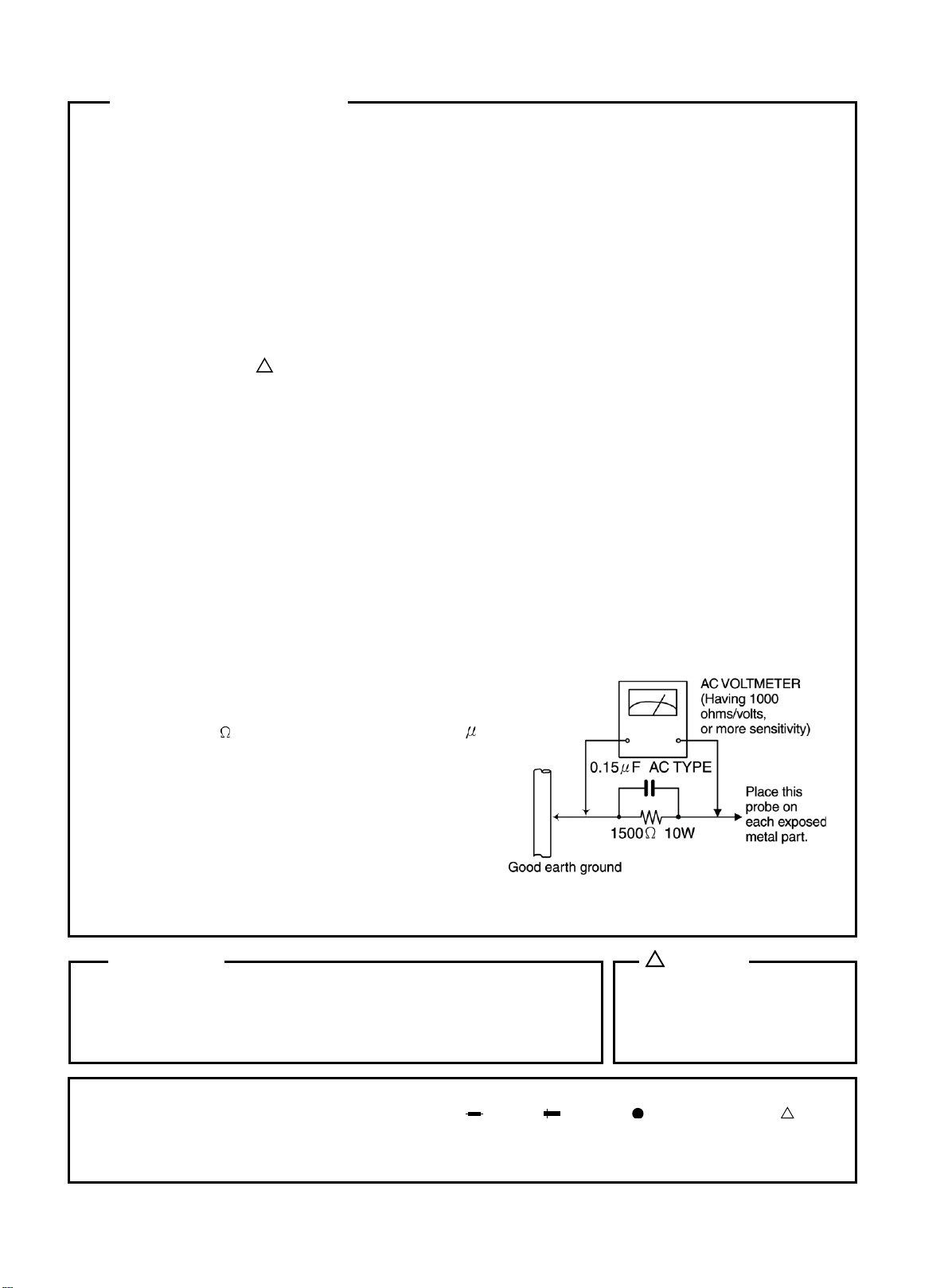
l Alternate check method
Plug the AC line cord directly into the AC outlet.
Use an AC voltmeter having, 1,000 ohms per volt
or more sensitivity in the following manner. Connect a 1,500 10W resistor paralleled by a 0.15
AC-type capacitor between an exposed metal part
and a known good earth ground. Measure the AC
voltage acros s the resi stor with the AC voltmeter.
Move the resistor connection to each exposed
metal part, pa rticularly any exposed metal part
having a return path to the chassis, and meausre
the AC voltage across the resistor. Now, reverse
the plug in the AC outlet andrepeat each
measurement. Voltage measured Any must not
exceed 0.75 V AC (r.m.s .). This corresponds to
0.5 mA AC (r.m.s.).
!
F
Warning
1. This equipment ha s been designed a nd manufa ctured to meet international safety standards.
2. It is the legal responsibility of the repairer to ensure that these safety standards are maintained.
3. Repairs must be made in a ccordance with the releva nt safety standards.
4. It is essential that safety critical components are repla ced by a pproved parts.
5. If mains voltage selector is provided, check setting for local voltage.
In regard with component parts appearing on the silk-screen printed side (parts side) of the PWB diagrams, the
parts that are printed over with black such as the resistor ( ), diode ( ) and ICP ( ) or identified by the “ ” mark
nearby are critical for safety.
When replacing them, be sure to use the parts of the same type and rating as specified by the manufacturer.
(Except the J and C version)
! CAUTION
Burrs formed during molding may be
left over on some parts of the
chassis. Therefore, pay attention to
such burrs in the case of preforming
repair of this system.
1-2
!
Page 3
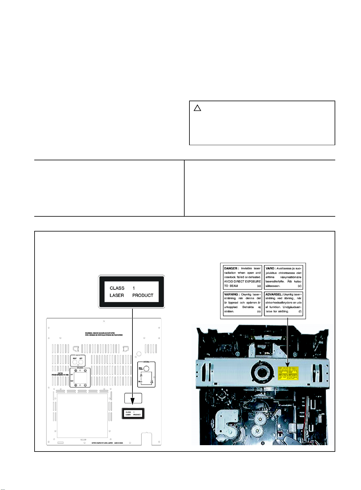
Important for laser products
1.CLASS 1 LASER PRODUCT
2.DANGER : Invisible laser radiation when open and
inter lock failed or defeated. Avoid direct exposure
to beam.
3.CAUTION :
Laser Unit. Do not disassemble the Laser Unit. Replace
the complete Laser Unit if it malfunctions.
4.CAUTION :
laser radiation and is equipped with safety switches
which prevent emission of radiation when the drawer
is open and the safety interlocks have failed or are
defeated. It is dangerous to defeat the safety
switches.
VARNING : Osynlig laserstrålning är denna del är
VARO : Avattaessa ja suojalukitus ohitettaessa olet
There are no serviceable parts inside the
The compact disc player uses invisible
öppnad och spårren är urkopplad. Betrakta
ej strålen.
alttiina näkymättömälle lasersäteilylle. Äl ä
katso säteeseen.
5.CAUTION : If safety switches malfunction, the laser
is able to function.
6.CAUTION :
mance of procedures other than those specified
herein may result in hazardous radiation exposure.
!
CAUTION Please use enough caution not
Use of controls, adjustments or perfor-
to see the bea m directly or touch
it in case of an adjustment or
operation check.
ADVARSEL : Usynlig laserstråling ved åbning, nå r
sikkerhedsafbrydere er ude af funktion.
Undgå udsættelse for stråling.
ADVARSEL : Usynlig laserstrå ling ved åpning, når
sikkerhetsbryteren er avslott. Unngå
utsettelse for stråling.
REPRODUCTION AND POSITION OF LABELS
WARNING LABEL
1-3
Page 4
Preventing static electricity
1. Grounding to prevent da mage by static electricity
Electrostatic discharge (ESD), which occurs when static electricity stored in the body, fabric, etc. is
discharged, can destroy the laser diode in the traverse unit (optical pickup). Take care to prevent this
when performing repairs.
2. About the e arth processing for the de struction prevention by static electricity
In the equipment which uses optical pick-up (laser diode), optical pick-up is destroyed by the static
electricity of the work environment.
Be careful to use proper grounding in the area where repairs are being performed.
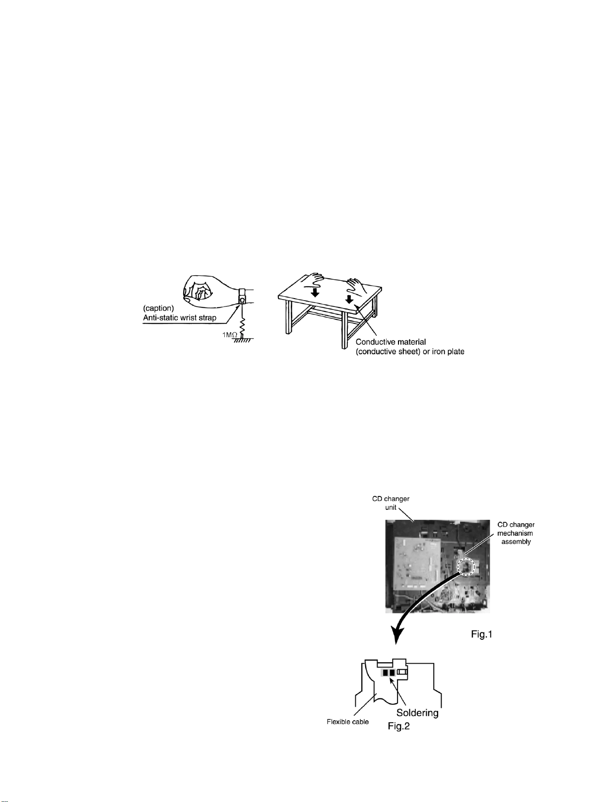
2-1 Ground the workbench
Ground the workbench by laying conductive material (such as a conductive sheet) or an iron plate
over it before placing the traverse unit (optical pickup) on it.
2-2 Ground yourself
Use an anti-static wrist strap to release any static electricity built up in your body.
3. Handling the optical pickup
1. In order to maintain quality during transport and before installation, both sides of the laser diode on the
replacement optical pickup are shorted. After replacement, return the shorted parts to their original
condition. (Refer to the text.)
2. Do not use a tester to check the condition of the laser diode in the optical pickup. The tester's internal
power source can easily destroy the laser diode.
4. Handling the CD cha nger unit (optical pickup)
1. Do not subject the CD changer unit (optical pickup) to strong shocks, as it is a sensitive, complex unit.
2. Cut off the shorted part of the flexible cable using nippers, etc. after replacing the optical pickup. For specific
details, refer to the replacement procedure in the text.
Remove the anti-static pin when replacing the CD changer
unit. Be careful not to take too long a time when attaching it
to the connector.
3. Handle the flexible cable carefully as it may break when
subjected to strong force.
4. It is not possible to adjust the semi-fixed resistor that adjusts the laser power. Do not turn it.
Attention when traverse unit is decomposed
* Please refer to "Disassembly method" in the text for pick
up and how to detach the CD changer mechanism.
1. Remove the CD changer unit.
2. Disconnect the harness from connector on the CD motor
board.
3. Solder is put up before the card wire is removed from connector
Cn601on the main board a s shown in Fig.1 a nd Fig. 2.
(When the wire is removed without putting up solder, the CD
pick-up assembly might destroy.)
4. Please remove solder after connecting the card wire with
CN601 when you install picking up in the substrate.
1-4
Page 5

Disassembly method
Commence disassembly of this set by removing the main units and then proceed to the components and
assemblies inside the units.
Replacement of the fuses and the power IC
n Top cover
n CD changer unit
n Front panel assembly
n Chassis unit
n CD changer unit
n Removing the main PCB
n Removing the CD changer mechanism assembly
n Removing the CD pickup
n Replacing the loading motor and belt of the CD changer tray
n Replacing the CD tray rotor belt of CD changer, and removing the motor
n Front panel assembly
n Removing the cassette deck mechanism
n Removing the earphone jack PCB
n Removing the control/FL PCB
n Removing the switch PCB and ACTIVE BASS EX. switch PCB
n Removing the cassette deck main motor, and replacing the main belts
n Removing the leaf switches of the cassette deck me chanism
n Removing the cassette deck heads
n Chassis unit
n Removing the 3-pin regulator
n Removing the power amp and supply PCB and the Power Trans PCB
n Removing the sub power PCB
1-5
Page 6
<Disasse mbly of the main blocks of this set>
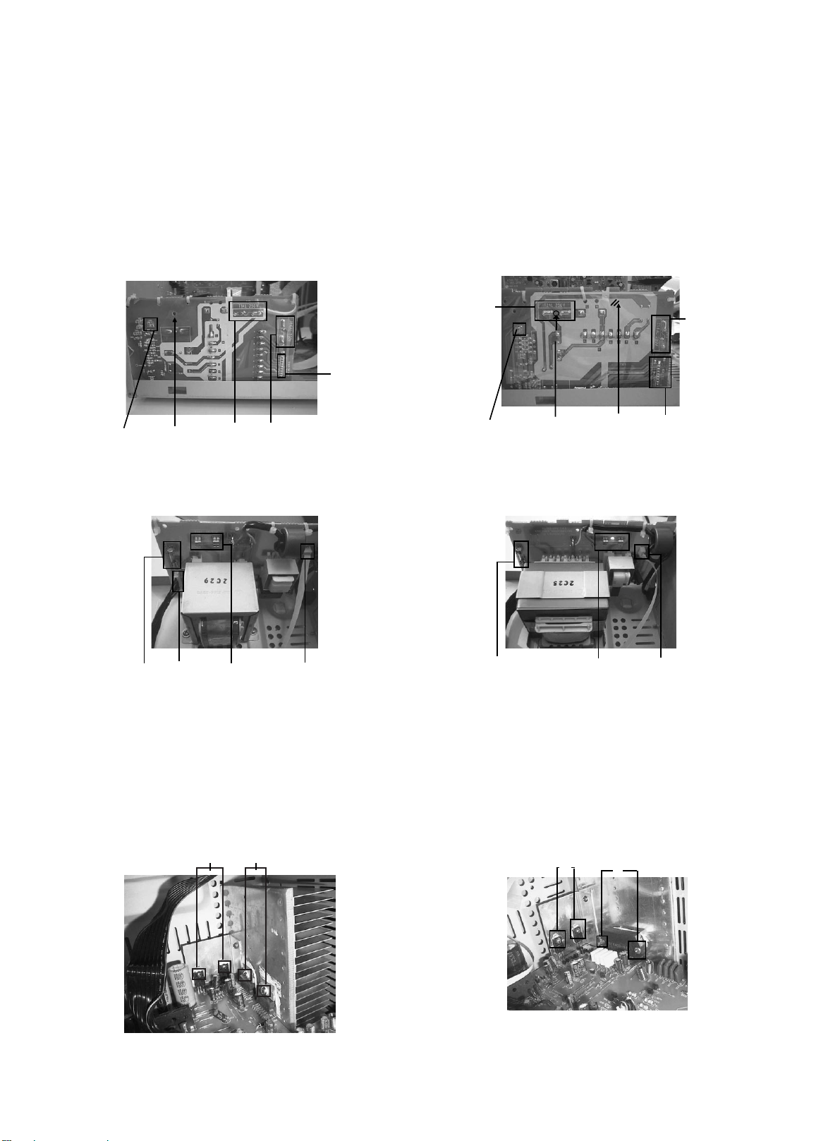
Repla c ement of the fuses and the power IC
n Re pla cing the fuse s (See Fig.1, Fig.4)
n
Prior to performing the following procedure, remove
the left side BOARD a nd remove tuner PCB (Fig.4,BB)
1. Replace the fuses in side.
[Caution] Be sure to use fuses with the specified ratings.
For CA-MXK10R/15R Fig.1(A)
BOTTOM SIDE
CN981
CAUTION
(don’t remove
the safety sheet
cover )
For CA-MXK10R/15R Fig.1(A)
Component SIDE
Fuse(F981)
T1AL 250V
Fuse(F952)
T1.6AL 250V
FW981
Fuse (F981)
T2AL 250V
CN981
For CA-MXK30R Fig.1(B)
BOTTOM SIDE
HOLE
Fuse Hole
For CA-MXK30R Fig.1(B)
Component SIDE
CAUTION
(don’t remove
the safety sheet
cover )
Fuse(F952)
FW951
Fuse (F952)
T1.6AL 250V
FW981
Fuse(F981)
T1AL 250V
CN981
n Repla cing the power IC (See Fig.2 to 3)
n
Prior to performing the following procedure, remove
the top cover.
1. Remove the two screws "A" from the heat sinkbetween
the power IC.
2. Remove the solder fixing the power IC.
For CA-MXK10R/15R Fig.2
W
A
Fuse(F952)
T1.6AL 250V
For CA-MXK30R Fig.3
Fuse (F981)
T2AL 250V
w
CN981
A
1-6
Page 7
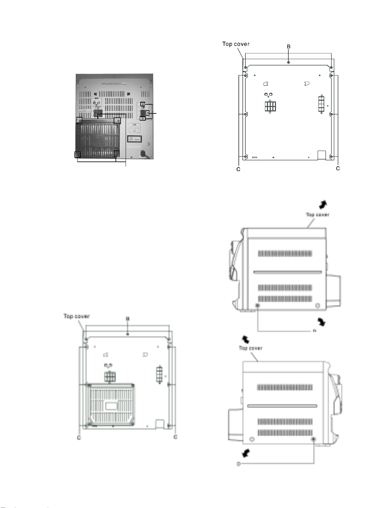
n Repla cing the he at sink cover
1. Remove the six screws "B" from the back pa nel.
2. Pull the heat sink cover outward.
For CA-MXK30R Fig.4
BB
B
n Re moving the top cover a nd two side s BOAR D
(See Fig.5 and 6)
1. Remove the six screws "C" that retain the top cover from the
rear of the body.
For CA-MXK15R Fig.5(B)
For CA-MXK10R/K30R Fig.6(A)
2. Remove the eight screws "C" and "D" that retain the top from
the two sides of the body.
3. Remove the top cover from the body by lifting it toward the
rear.
For CA-MXK10R/K30R Fig.5(A)
1-7
Page 8
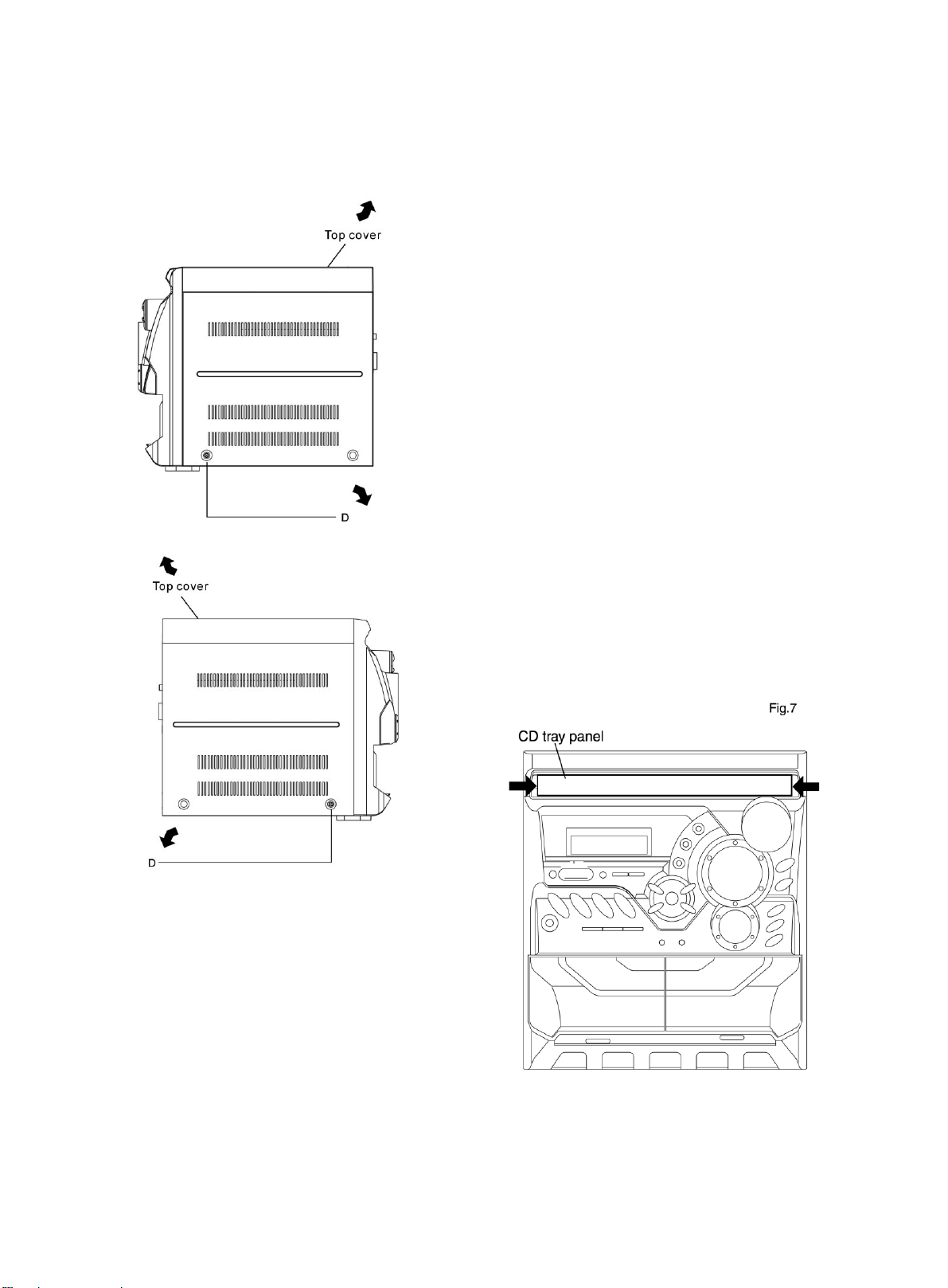
For CA-MXK15R Fig.6(B)
n Removing the CD changer unit
(See Fig.7 to 10)
n
Prior to performing the following procedures, remove
the top cover and both sides BOARD.
[Caution] Although the CD mechanism unit can be
removed without removing the CD tray
panel, it is still recommended to remove it
in order to prevent da mage.
a. From the front panel side of this set, push in the sec-
tions marked with arrows and pull out the CD tray
toward the front.
b. Remove the CD tray panel by pushing both of its ex-
tremities upward in the direction of the arrows.
c. Push the CD tray deep into the set.
1. Disconnect the card wires from the CD PCB CN703
and CN203.
2. From the rear of the set, remove the two screws "E"
and two serews "G" on the front panel left and right
side.
3. Handle the CD changer unit rear, ta ke out unit.
1-8
Page 9
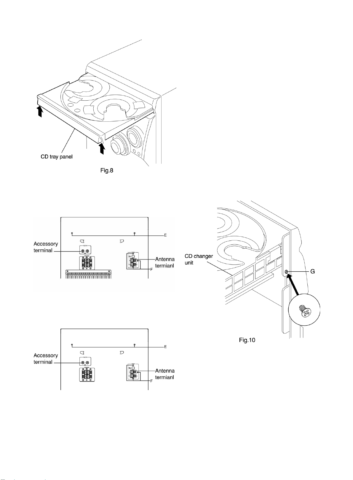
For CA-MXK10R/30R Fig.9(A)
For CA-MXK15R Fig.9(B)
1-9
Page 10
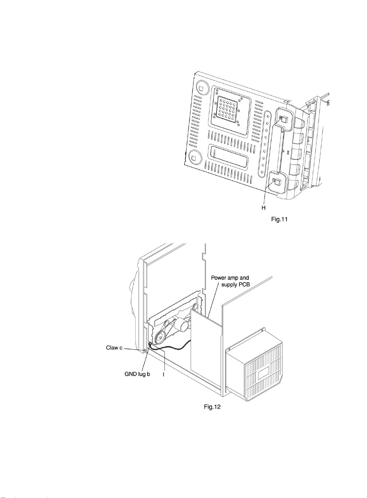
n Removing the front panel assembly
(See Fig.11 and 12)
n
Prior to performing the following procedures, remove
the top cover and both sides board.
n
Also remove the CD cha nger unit.
1. Disconnect the parallel wire and card wire from the
connectors CN702,CN701,CN101on the power a mp
and supply PCB.
2. Remove the two screws "H" retaining the front panel
assembly onto the bottom of the body.
3. Remove the screw "I" retaining the cassette deck
mechanism and then remove then GND lug "b" that
comes from the power a mp and supply PCB.
4. Disengage the claws "c" on both side s at the bottom
of the front panel assembly and then remove the
assembly.
1-10
Page 11

<Disa ssembly of units a nd a sse mbly inside this set>
n Removing the CD PCB
(See Fig.13 and 14)
n
Prior to performing the following procedures, remove
the top cover and both sides board.
n
Also remove the CD cha nger unit.
1. Disconnect the wires from CN603A, CN603B and
CN604 on the CD PCB, which is located on the back
side of the CD changer unit.
2. The two screws "J" that retain the CD PCB should
be removed.
3. Remove the CD PCB by pulling it toward the side
where the CN601 is located.
4. Using solder, short the CD pickup to connect to short
round.
[Caution] After re-connecting the wires, be sure to
remove the shorting solder from the GND
connection.
5. Disconnect the card wire from the conne ctor CN601
on the main PCB and then remove the main PCB.
1-11
Page 12

n Removing the CD changer mechanism
assembly
n
Prior to performing the following procedures, remove
the top cover and both sides board.
n
Also remove the CD cha nger unit.
1. Remove the screws "d" from the front chuch ba se of
the CD cha nger me cha nism unit.
2. Turn the CD changer mechanism cover base and
remove the screws "e" connecting the unit to the CD
changer mecha nism assembly.
3. Removing the four screws "k" retaining the CD
mechanism holder assembly.
[Caution] When repla cing the CD cha nger mecha nism
assembly, be sure not to mistake the
positions of the silver color and copper color
spring.
(See Fig.15 to 17)
1-12
Page 13

n Removing the CD pickup (See Fig.18)
n
Prior to performing the following procedures, re-
move the top cover and both sides board.
n
Also remove the CD changer unit.
n
Also remove the CD changer mechanism.
1. Widen the section "f".
2. While keeping the section "f" wide open, push
the section "g" in the direction of the arrow to
remove the shaft, and then remove the CD pickup.
n Replacing the loa ding motor and rotor belt
of the CD changer (See Fig .19)
n
Prior to performing the following procedure, re-
move the top cover.
n
Also open the CD changer tray.
1. Remove the two screws "L" retaining the CD
changer tray loading motor.
2. Remove the two screws "M" retaining the gear
plate and take it out, after remove the rotor belt
from the pulley.
n Replacing the CD turn table and remov-
ing the motor (See Fig. 20 and 21)
n
Prior to performing the following procedures, re-
move the top cover.
n
Also remove the CD changer unit.
1. Remove the one screws "N" retaining the CD (Turn
table).
2. Remove the two screws "O" retaining the stopper brackets on both sides of the CD cha nger unit.
3. Remove the stopper brackets from both sides of
the CD changer unit.
4. Pull out the CD tray from the CD changer unit, all
the way and lift the tray (u/~ ward) to remove.
5. Remove the gear and after push out the tray motor
locker and pull out the tray motor from the CD
tray.
1-13
Page 14

n Removing the cassette deck mechanism
(See Fig.22)
n
Prior to performing the following procedure, remove
the top cover and both sides board.
n
Also remove the CD cha nger unit.
n
Also remove the front panel assembly.
1. Remove the five screws "Z" retaining the ca ssette deck
mechanism.
n Removing the earphone jack PCB
(See Fig.23)
n
Prior to performing the following procedure, remove
the top cover and both sides board.
n
Also remove the CD cha nger unit.
n
Also remove the front panel assembly.
1. Remove the screw with the washer, "P" that retains
the earphone jack PCB.
nRemoving the control/FL PCB
(See Fig.24)
n
Prior to performing the following procedure, remove
the top cover and both sides board. Also remove the
CD cha nger unit.
n
Also remove the CD cha nger unit.
n
Also remove the CD cha nger unit.
1. Remove the four screws "Q" that retain the control/FL
PCB from the back of the front pa nel unit.
1-14
Page 15

Removing the switch PCB and sound
mode and CD function switch PCB
(See Fig.24 to 27)
Prior to performing the following procedures, remove
the top cover and both sides board.
Also remove the CD changer unit.
Also remove the front panel assembly.
1. Pull out the volume control knob from the front of the
front panel assembly.
2. Remove the four screws "Q" retaining the front panel
assembly.
3. Remove the control / FL PCB.
4. Remove the eleven screws "R" retaining the switch
(key 1) PCB.
5. Remove the three screws "S" retaining the sound mode
(key 2) switch PCB.
6. Remove two screws "T" retaining the CD function (key
3) switch PCB.
1-15
Page 16

n Re moving the ca ssette de ck main motor ,
and re placing the main belts
(See Fig. 22, 28 and 29)
n
Prior to performing the following procedures, remove
the top cover and both sides board.
n
Also remove the CD cha nger unit.
n
Also remove the front panel assembly.
1. Remove the five screws "z" retaining the ca ssette deck
mechanism.
2. Remove the ca ssette deck me chanism.
3. Remove the two screws "t" retaining the main motor
from the front side of the ca ssette deck.
[Caution] After attaching the main motor, check the
orientation of the motor and the polarity of
the wires.
4. From the backside of the cassette deck, remove the
main motor and two main belts.
[Caution] The lengths of the cassette A (playback
only) and cassette B (record/play) main
belts are different. When atta ching the main
belts, use the longer belt for cassette A.
n Removing the leaf switches of the cas-
sette deck mechanism
(See Fig. 22 and 30)
n
Prior to performing the following procedures, remove
the top cover and both sides board.
n
Also remove the CD cha nger unit.
n
Also remove the front panel assembly.
1. Remove the five screws "O" that retain the cassette
deck mechanism.
2. Remove the ca ssette deck me chanism.
3. Turn the cassette deck mechanism upside down.
4. Remove the solder from around the leaf switches.
5. Pull out the leaf switches from the front side of the
cassette deck mechanism.
1-16
Page 17

n Removing the cassette deck heads
(See Fig. 22 and 31)
n
Prior to performing the following procedures, remove
the top cover and both side board.
n
Also remove the CD cha nger unit.
n
Also remove the front panel assembly.
1. Remove the five screws "O" that retain the cassette
deck mechanism.
2. Remove the ca ssette deck mecha nism a nd pla ce it so
that the front side faces up.
3. Remove the solder from the bottom side of the head
terminal and disconnect the wire.
4. Remove the screw "U" that retains the head.
5. Remove the screw "V" that retains the head.
6. Hold the head and slide it in the direction of the arrow
to remove it.
n Removing the 3-pin regulator
(See Q904, Q907, 32 and 33)
n
Prior to performing the following procedures, remove
the top cover and both sides board.
1. Remove the two screws "A" that connect the heat
sink cover to the rear panel.
2. Pull the heat sink outward.
3. Remove the screw "W" that retains the heat sink the
3-pin terminal regulator Q904,Q907.
4. Remove the solder fixing the 3-pin regulator.
For CA-MX K30R Fig.32
w
For CA-MX K10R/K15R Fig. 33
W
A
A
1-17
Page 18

n Removing the power amp and supply
PCB and the power trans PCB
(See Fig. 2, 3, 32, 34 to 37)
For CA-MXK10R/K15R Fig.34(A)
n
Prior to performing the following procedures, remove
the top cover and both sides board.
n
Also remove heat sink cover .(Fig.4)
1. Remove the two screws "A" connecting the heat sink
cover to the rear panel.(Fig.2, 3)
2. Pull out the heat sink cover toward you.
3. Remove the three (CA-M XK10/K15R)/ four(CA-MXK30)
screws "AA" form the (CA-MXK10/K15R) chassis /
MX-K30 back panel between the heat sink.
4. Remove the three screws "X" that retain the speaker
terminals and AUX terminal.
5. Remove the screw "YY" that retains the rear panel,
and then remove the re ar panel.
6. Disconnect the parallel wires from the connectors
FW951 and CN981 on the power tra n s PCB.
7. Remove the screw "Z" that retain the power a mp a nd
supply PCB and then remove the assembly.
8. Remove the cla mp of AC power cord from the cha ssis.
9. Remove the four screws "AB" that retain the power
trans PCB and then remove the assembly.
X
BB
CLAMP
YY
For CA-MXK10R/K15R Fig.34(A)
For CA-MXK10R/K15R Fig.35 (A)
Component SIDE
Fuse (F952)
T1.6AL 250V
FW981
Fuse(F981)
T1AL 250V
Fig.36
CN981
For CA-MXK30R Fig.35(B)
Component SIDE
Fuse(F952)
T1.6AL 250V
For CA-MXK10R/K15R Fig.37 (A)
AB
Fuse (F981)
T2AL 250V
For CA-MXK30R Fig.34(B)
CN981
For CA-MXK30R Fig.37(B)
Fuse F981
T2AL 250V
AB
X
Y
CLAMP
YY
Fuse F952
T1.6AL 250V
FW 951
1-18
Page 19

Adjustment method
Measurement instruments required
for adjustment
1. Low frequency oscillator,
This oscillator should have a capacity to output 0dB
to 600ohm at an oscillation frequency of 50Hz20kHz.
2. Attenuator impedance : 600ohm
3. Electronic voltmeter
4. Frequency counter
5. Wow flutter meter
6. Test tape
VT712 : For Tape speed and wow flutter ( 3kHz)
VT703 : For Head a ngle(10kHz),Play ba ck frequency
characteristics(1kHz), and dubbing
frequency characteristics (63,1,10kHz)
7. Blank tape
TAPE I : AC-225
8. Torque gauge : For play and back tension forward ;
TW2111A, Reverse ; TW2121A Fast Forward and
Rewind ; TW2231A
9. Test disc: CTS-1000(12cm),GRG-1211(8cm)
10. Jitter meter
Measurement conditions
Power supply voltage
AC230V (50Hz)
Measurement
output terminal : Speaker out
: TP101(Measuring for TUNER/
DECK/CD)
: Dummy load 6ohm
Radio input signal
AM modulation frequency : 400Hz
Modulation factor : 30%
FM modulation frequency : 1kHz
Frequency displacement : 22.5kHz
Frequency Range
FM 87.5MHz~108MHz
MW 522kHz~1629kHz
LW 144kHz~228kHz
Standard me asurement positions of
volume and switch
Power: Standby (Light STANDBY Indicator)
S, A, BASS : OFF
Sound mode : OFF
Main VOL. : 0 Minimum
Travers mecha set position : Disc 1
Precautions for measurement
1. Apply 30pF and 33kohm to the IF sweeper output
side and 0.082
sweeper input side.
2. The IF sweeper output level should be made as low as
possible within the adjustable range.
3. Since the IF sweeper is a fixed device, there is no
need to adjust this sweeper.
4. Since a ceramic oscillator is used, there is no need to
perform any MPX adjustment.
5. Since a fixed coil is used, there is no need to adjust
the FM tracking.
6.The input and output earth systems are separated. In
case of simultaneously measuring the voltage in both
of the input and output syst ems with an electronic
voltmeter for two cha nnels, theref ore, the e arth should
be connected particularly.
7. In the case of BTL connection amplifier, the minus
terminal of speaker is not for earthing. Therefore, be
sure not to connect any other earth terminal to this
terminal. This system is of an OTL system.
F and 100kohm in series to the
1-19
Page 20

Arrangement of adjusting positions
Tape recorder section
Items
Cassette Head
Azimuth Alignments
Recordi ng Bi as
Frequency Alignment
Tuner section
Items
AM Tracking
Alignments
Measurement
condi tions
Test tape :
VT703 (10kHz)
Measurement
output terminal :
Left and Right
speaker output
(6-ohm loaded)
or Headphone
Output
(32-ohm loaded)
Test tape :
TYPE I AC-225
Measurement
output terminal :
Erase head
terminal
(CN308 8-Pin)
Measurement
condi tions
Input signal :
529kHz (530kHz)
603kHz (600kHz)
Measurement
point :
Resistor(R3)
terminal
Measu rement meth o d
1. Playback the test tape VT703 (10KHz) or equivalent.
2. Adjust the head azimuth screw to obtain maximum
output and both output of L / R is in 3dB.
3. Put on the screw lock paint after alignments.
1. Insert the recording tape in deck-B.
2. Starting the recording.
3. Adjust the oscillation frequency to 80KHz+/-3KHz
by core of Oscillation coil of L301.
Measurement method
1. Set the Signal Generator signal to 529KHz (530KHz)
the feed to Loop Antenna.
2. Receiving the signal and the adjust the OSC coil
L4(MW)/L5(LW) obtain the V.T is 1.40V +/-0.05V.
3. Change the receiving frequency to 603KHz (600KHz).
4. Adjust the Antenna coil L2(MW)/L3(LW) obtain
maximum sensiti vity .(Adjust the SSG output to
out of AGC range.)
Standar d
values
Maximum output Head azimuth
80kHz+/-3kHz Bias coil: L301
Standard
values
V.T :
1.40V+/-0.05V
Maximum
sensitivity
Ad ju stin g
posi tions
screw
Adjust the
head azimuth
screw only
when the head
has been
changed.
Use the HighImpedance
Probe or
Frequency
counter input.
Ad ju stin g
posi tions
OSC coil:
L4(MW)/L5(LW)
Antenna coil:
L2(MW)/L3(LW)
Adjust the OSC
coil only when
the AM coil
block has been
changed.
AM IFT Alignments Input signal :
530kHz (529kHz)
1. Set the receiving frequency to 529KHz (530KHz ).
2. Feed the 450KHz signal to AM antenna input.
3. Adjust the IFT Block T1 obtain to maximum output.
(Adjust the SSG output to out of AGC range.)
Note: The adjustment of CD section is not required.
1-20
Maximum output IFT(T1)
Adjust the IFT
only when the
IFT b lo c k ha s
been changed.
Page 21

Flow of functional operation until TOC read
Power ON Play Key
Tracking error waveform at TOC reading
n
pin 20 of
IC611(TE)
Approx.3sec
Slider turns REST
SW ON.
Automatic tuning
of TE offset
Laser ON
Detection of disc
Automatic tuning of
Focus offset
Automatic measurement of
Focus S-curve amplitude
Disc is rotated
Focus servo ON
(Tra cking servo ON)
Check Point
Confirm that the voltage at the pin5
of CN602 is "H"\"L"\"H".
Check that the voltage at the pin40
of IC601 is + 5V?
Confirm that the Focus error S-cuve
signal at the pin32 of IC601 is
approx.2Vp-p
Confirm that the signal from pin24
IC601 is 0V as a accelerated pulse
during approx.400ms.
Approx
1.8V
VREF
Disc states
to rotate
Automatic measurement
of TE amplitude and
automatic tuning of
TE balance
Tracking
servo
off states
Tracking
servo
on states
Disc to be
braked to
stop
TOC reading
finishes
500mv/div
2ms/div Fig.1
Automatic measurement of
Tracking error amplitude
Automatic tuning of
Tracking error balance
Automatic tuning of
Focus error balance
Automatic tuning of
Focus error gain
Automatic tuning of
Tracking error gain
TOC reading
Play a disc
Confirm the waveform of the Tracking error signal. at the pin 20 of IC61 1
(R643) (See fig-1)
Confirm the eys-pattern at the lead
of Tp3
1-21
Page 22

Maintenance of laser pickup
(1) Cleaning the pick up lens
Before you replace the pick up, please try
to clean the len s with a alcohol soaked cotton swab.
(2) Life of the la ser diode
When the life of the la ser diode has expired,
the following symptoms will a ppe ar.
1. The level of RF output (EFM output: a mpli
tude of eye pattern) will below.
Repla cement of laser pickup
(3) Semi-fixed resistor on the APC PC board
The semi-fixed resistor on the APC printed circuit board which is attached to the pickup is used to adjust the
laser power. Since this adjustment should be performed to match the chara cteristics of the whole optical block,
do not touch the semi-fixed resistor.
If the la ser power is lower than the specif ied value, the la ser diode is almost worn out, and the laser pickup should
be replaced.
If the semi-fixed resistor would be adjusted when the pickup operates normally, the laser pickup may be damaged due to excessive current.
1-22
Page 23

Description of major ICs
n AN22000A (IC611) : CD-DA Head Amp.
1. Terminal layout 2. Pin function
1 3 2
16 17
3. Block diagram
1-23
Page 24

n BA15218DIP (IC102) : Dual low noise operational amp.
1. Terminal layout
n BA5936S (IC621) : 6 channel BTL driver
1. Block diagram
2. Pin function
1-24
Page 25

n LA1833 (IC1) : 1chip AM/FM, MPX tuner system
1. Block diagram
2. Pin function
1-25
Page 26

n LC72136N (IC2) : PLL Frequency synthesizer
1.T ermin al layout
2. Block diagram
3. Pin function
1-26
Page 27

n TA8189N (IC401) : REC/PB amp.
1. Terminal layout 2. Block diagram
3. Pin function
1-27
Page 28

n TC74HC4094AP (IC402) : 8-bit shift and store resister
1.T ermin al layout
2. Block diagram
1-28
Page 29

n TDA7440D (IC101) : Audio processor
1. Terminal layout
2. Block diagram
1-29
Page 30

BU1924F (IC3) : RDS/RBDS decoder
1. Terminal layout
2. Block diagram
3. Pin function
1-30
Page 31

n MN662748RPM (IC601) : Digital servo & digital signal processor
1. Terminal layout
2. Pin function
1-31
Page 32

MX-K10R/K30R/K15R
VICTOR COMPAN Y OF JAPAN, LIMITED
AUDIO & COMMUNICATION BUSINESS DIVISION
PERSONAL & MOBILE NETWORK B.U.10-1, 1 Chome, Ohwatari-machi, maebashi-city, 371-8543, Japan
No.21138
Printed in Japa n
200212
 Loading...