

JVC MX-GB6, MX-GB5 Owner’s Manual
JVC
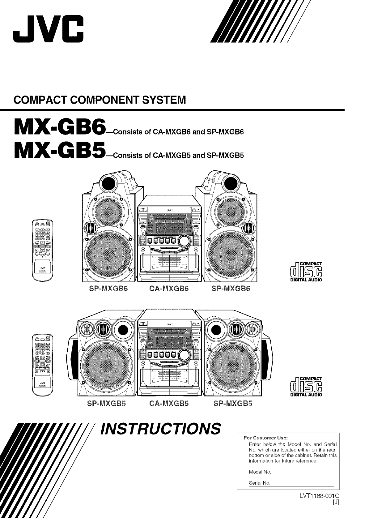
COMPACT COMPONENT SYSTEM
MX-G B6_onsists
MX-G BS_onsists
It
SP°MXGB6 CA-MXGB6 SP-MXGB6
of CA-MXGB6 and SP-MXGB6
of CA-MXGB5 and SP-MXGB5
DIGITALAUDIO
SP-MXG85 CA-MXGB5 SP-MXGB5
INSTRUCTIONS
DIGITAL AUDIO
For Customer Use:
Enter below the Model No. and Serial
No. which are located either on the rear,
bottom or side of the cabinet. Retain this
information for future reference.
Model No.
Serial No.
LVT1188o001C
[4
Warnings, Cautions and Others
Mises en garde, precautions et indications diverses
CAUTION
To reduce the risk of electrical shocks, fire, etc.:
1. Do not remove screws, covers or cabinet.
CAUTION: TO REDUCE THE RISK OF ELECTRIC SHOCK.
REFER SERVICING TO QUALIFIED SERVICE PERSONNEL.
DO NOT REMOVE COVER (OR BACK)
NO USER SERVICEABLE PARTS INSIDE.
The lightning flash with arrowhead symbol,
within an equilateral triangle is intended to
alert the user to the presence of uninsulated
"dangerous voltage" within the product's
enclosure that may be of sufficient
magnitude to constitute a risk of electric
shock to persons.
The exclamation point within an equilateral
triangle is intended to alert the user to the
presence of important operating and
maintenance (servicing) instructions in the
literature accompanying the appliance.
2. Do not expose this appliance to rain or moisture.
ATTENTION
Afin d'eviter tout risque d'electrocution, d'incendie, etc.:
1. Ne pas enlever les vis ni les panneaux et ne pas
ouvrir le coffret de I'appareil.
2. Ne pas exposer I'appareil 9.la pluie ni 9.I'humidit&
Caution -- VII STANDBY/ON switch!
Disconnect the mains plug to shut the power off completely.
The _)/I STANDBY/ON switch in any position does not
disconnect the mains line. The power can be remote control-
led.
WARNING: TO REDUCE THE RISK OF FIRE
OR ELECTRIC SHOCK, DO NOT EXPOSE
THIS APPLIANCE TO RAIN OR MOISTURE.
For U.S.A.
This equipment has been tested and found to comply with the limits
for a Class B digital device, pursuant to part 15 of the FCC Rules.
These limits are designed to provide reasonable protection against
harmful interference in a residential installation.
This equipment generates, uses and can radiate radio frequency
energy and, if not installed and used in accordance with the
instructions, may cause harmful interference to radio
communications. However, there is no guarantee that interference
will notoccur in a particular installation. If this equipment does cause
harmful interference to radio or television reception, which can be
determined by turning the equipment off and on, the user is
encouraged to try to correct the interference by one or more of the
following measures:
Reorient or relocate the receiving antenna.
Increase the separation between the equipment and receiver.
Connect the equipment into an outlet on a circuit different from that
to which the receiver is connected.
Consult the dealer or an experienced radio/TV technician for help.
Attention -- Commutateur _/t STANDBY/ON!
Deconnecter la fiche de secteur pour couper completement
le courant. Le commutateur 4,_)/tSTANDBY/ON ne coupe
jamais completement la ligne de secteur, quelle que soit sa
position. Le courant peut 6tre t61ecommand&
IMPORTANT FOR LASER PRODUCTS
1. CLASS 1 LASER PRODUCT
2. CAUTION: Do not open the top cover. There are no user
serviceable parts inside the unit; leave all servicing to
qualified service personnel.
3. CAUTION: Visible and invisible laser radiation when open
and interlock failed or defeated. Avoid direct exposure to
beam.
4. REPRODUCTION OF LABEL: CAUTION LABEL,
PLACED INSIDE THE UNIT.
IMPORTANT POUR PRODUITS LASER
1. PRODUIT LASER CLASSE 1
2. ATTENTION: N'ouvrez pas le couvercle sup@ieur. II n'y a
aucune piece reparable par I'utilisateur a I'interieur de
I'appareil; confiez toute reparation & un personnel qualifie.
3. ATTENTION: Risque de radiations laser visible et invisible
quand I'appareil est ouvert et que le systeme de
verrouillage ne fonctionne pas ou a ete mis hors service.
Evitez toute exposition directe au rayon.
4. REPRODUCTION DE L'ETIQUETTE: ETIQUETTE DE
PRECAUTION PLAC#:E ,&,L'INTERIEUR DE
L'APPAREIL.
6-1
For Canada/pour le Canada
CAUTION: TO PREVENT ELECTRIC SHOCK, MATCH WIDE
BLADE OF PLUG TO WIDE SLOT, FULLY INSERT.
ATTENTION: POUR EVITER LES CHOCS ELECTRIQUES,
INTRODUIRE LA LAME LA PLUS LARGE DE LA FICHE DANS
LA BORNE CORRESPONDANTE DE LA PRISE ET POUSSER
JUSQUAU FOND.
For Canada/pour le Canada
THIS DIGITAL APPARATUS DOES NOT EXCEED THE CLASS B
LIMITS FOR RADIO NOISE EMISSIONS FROM DIGITAL
APPARATUS AS SET OUT IN THE INTERFERENCE-CAUSING
EQUIPMENT STANDARD ENTITLED "DIGITAL APPARATUS,"
ICES-003 OF THE DEPARTMENT OF COMMUNICATIONS.
CET APPAREIL NUMERIQUE RESPECTE LES LIMITES DE
BRUITS RADIOELECTRIQUES APPLICABLES AUX APPAREILS
NUMIRIQUES DE CLASSE B PRESCRITES DANS LA NORME
SUR LE MATERIEL BROUILLEUR:"APPAREILS NUMERIQUES",
NMB-003 EDICTEE PAR LE MINISTRE DES
COMMUNICATIONS.
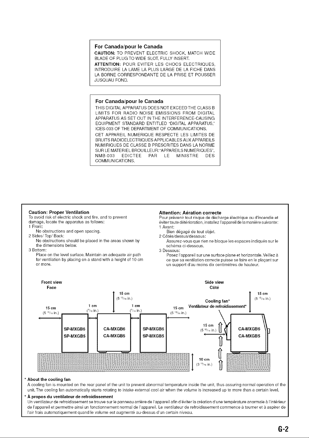
Caution: Proper Ventilation
To avoid risk of electric shock and fire, and to prevent
damage, locate the apparatus as follows:
1 Front:
No obstructions and open spacing.
2 Sides/Top/Back:
No obstructions should be placed in the areas shown by
the dimensions below.
3 Bottom:
Place on the level surface. Maintain an adequate air path
for ventilation by placing on a stand with a height of 10 cm
or more.
Front view
Face
I 15 cm
15 cm
(5 _5/_in.) (7h_in.)
SP-MXGB6
SP-MXGB5
1 cm
(5 W_6in.)
CA-MXGB6
CA-MXGB5
1 cm
(7/_ in.)
SP-MXGB6
SP-MXGB5
Attention: Aeration correcte
Pour pr#venir tout risque de d#charge 61ectrique ou d'incendie et
eviter toute det6rioration, installez I'appareil de lamaniere suivante:
1 Avant:
Bien degage de tout objet.
2 C6tes/dessus/dessous:
Assurez-vous que rien ne bloque les espaces indiques sur le
schema ci-dessous.
3 Dessous:
Posez I'appareil sur une surface plane et horizontale. Veillez &
ce que sa ventilation correcte puisse se faire en le plaqant sur
un support d'au moins dix centimetres de hauteur.
Side view
C6te
(5W_6in.)
I 15cm
15 cm
(5 W_ in.)
Ventilateur de retroidissement*
Cooling fan*
15 cm '
(5 _5/_in.)
CA-MXGB6 1
CA-MXGB5
,oom i !I i1
]
(3 _5/_6in.) 1_
* About the cooling tan
A cooling fan is mounted on the rear panel of the unit to prevent abnormal temperature inside the unit, thus assuring normal operation of the
unit. The cooling fan automatically starts rotating to intake external cool air when the volume is increased up to more than a certain level.
* Apropos du ventilateur de retroidissement
Un ventilateur de refroidissement se trouve sur le panneau arriere de I'appareil afin d'eviter la creation d'une temperature anormale & I'interieur
de I'appareil et permettre ainsi un fonctionnement normal de I'appareil. Le ventilateur de refroidissement commence a tourner eta aspirer de
I'air frais automatiquement quand le volume est augmente au-dessus d'un certain niveau.
6-2
Introduction
We would like to thank you for purchasing one of our JVC products.
Before operating this unit, read this manual carefully and thoroughly to
obtain the best possible performance from your unit, and retain this manual
for future reference.
AboutThisManual
This manual is orgmlized as follows:
• The manual mainly explains operations using the
buttons and controls on the unit. You can also use the
buttons on the remote control if they have the same or
similar names (or marks) as those on the unit.
If operation using the remote control is different from
that using the unit, it is then explained.
• Basic trod common infommtion that is tile same for many
functions is grouped in one place, and is not repeated in
each procedure. For instance, we do not repeat the
information about turning on/off the unit, setting the
volume, chtmging the sound effects, and others, which are
explained in the section "Common Operations" on pages 9
toll.
• The following marks are used in this manual:
damage or risk of fire/electric shock.
Gives you warnings mid cautions to prevent
Also gives you information which is not good
for obtaining the best possible performance
from tile unit.
know.
Gives you information mid hints you had better
Precautions
Installation
• Do not grasp tile control knobs when moving or carrying
tile unit.
• Install in a place which is level, dry trod neither too hot nor
too cold--between 5°C (41°F) and 35°C (95°F).
• Install the unit in a location with adequate ventilation to
prevent internal heat built-up in the unit.
• Leave sufficient disttmce between the unit and the TV.
• Keep the speakers away from the TV to avoid interference
with TV.
Power sources
• When unplugging from tile wall outlet, always pull tile
plug, not tile AC power cord.
DO NOT handle the AC power cord with wet
hands.
Moisturecondensation
Moisture may condense on tile lens inside tile unit in tile
following cases:
• After starting heating in tile room
• In a damp room
• If the unit is brought directly from a cold to a warm place
Should this occur, tile unit may malffmction. In this case,
leave tile unit turned on for a few hours until tile moisture
evaporates, unplug tile AC power cord, and then plug it in
again.
Others
• Should rely metallic object or liquid fall into tile unit,
unplug tile unit and consult your dealer before operating
any furHler.
• If you are not going to operate tile unit for an extended
period of time, unplug tile AC power cord from tile wall
outlet.
DO NOT disassemble the unit since there are no I
user serviceable parts inside.
If tmything goes wrong, unplug tileAC power cord and
consult your dealer.
I
I
I
I& DO NOT install the unit in a location near heat
sources, or in a place subject to direct sunlight,
excessive dust or vibration.
I
Contents
Location of the Buttons and Controls ....................... 3
Front Panel ................................................................. 3
Remote Control .......................................................... 5
Getting Started ............................................................ 6
Unpacking .................................................................. 6
Putting the Batteries into the Remote Control ........... 6
Connecting Antennas ................................................. 6
Connecting Speakers .................................................. 7
Connecting Other Equipment ..................................... 8
Canceling the Display Demonstration ....................... 8
Common Operations .................................................. 9
Turning On or Off the Power ....................................... 9
Setting the Clock ........................................................ 9
Selecting the Sources ................................................... 9
Adjusting the Volume ............................................... 10
Reinforcing the Bass Sound ..................................... 10
Enjoying the Powerful Sound--RHYTHM AX ....... 10
Selecting the Sound Modes ...................................... 11
Turning On or Off the Key-touch Tone .................... 11
Listening to the Radio .............................................. 12
Tuning in to a Station--Auto Search ....................... 12
Presetting Stations .................................................... 12
Tuning in to a Preset Station .................................... 12
Playing Back CDs ..................................................... 13
Loading CDs ............................................................ 13
Playing Back CDs--AII Disc and One Disc ............ 13
Basic CD Operations ................................................ 15
Changing the MP3 Playback Mode .......................... 17
Turning On or Off the Resume Play for MP3 Disc .. 17
Programming the Playing Order of the Tracks
--Program Play .................................................. 18
Playing at Rtmdom--Random Play ......................... 19
Repeating Tracks or CDs--Repeat Play .................. 19
Prohibiting Disc Ejection--Carrousel Lock ............ 19
Playing Back Tapes ................................................... 20
Playing Back a Tape ................................................. 20
Recording .................................................................. 21
Recording a Tape on Deck B .................................... 21
Dubbing Tapes .......................................................... 22
CD Synchronized Recording ..................................... 22
Using the Timers ....................................................... 23
Using Daily Timer .................................................... 23
Using Recording Timer ............................................ 24
Using Sleep Timer .................................................... 25
Timer Priority ........................................................... 25
Maintenance .............................................................. 26
Troubleshooting ........................................................ 27
Specifications ............................................................. 28
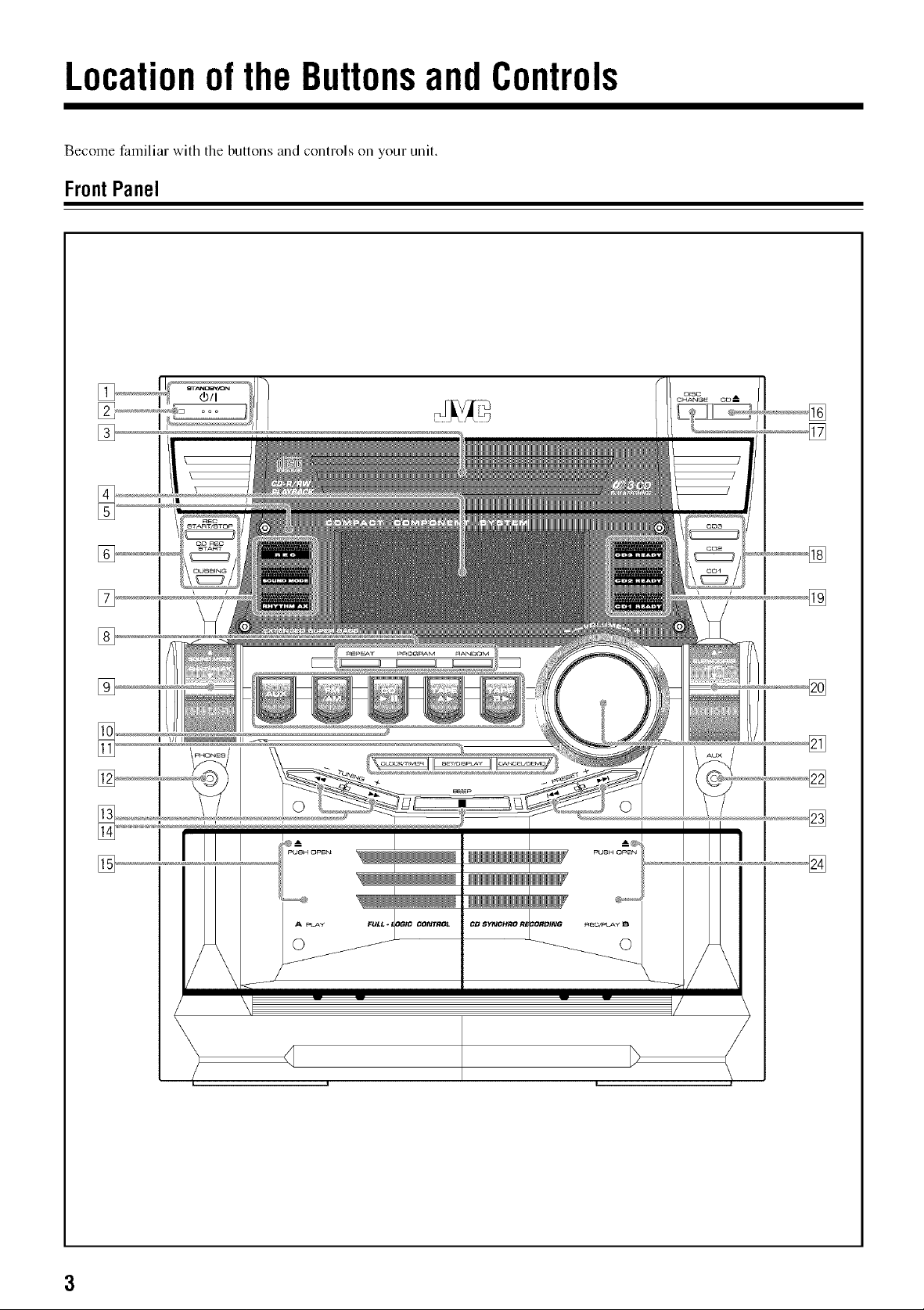
Locationofthe ButtonsandControls
Become familiar with the buttons and controls oil your unit.
FrontPanel
[]
[]
I I
I I
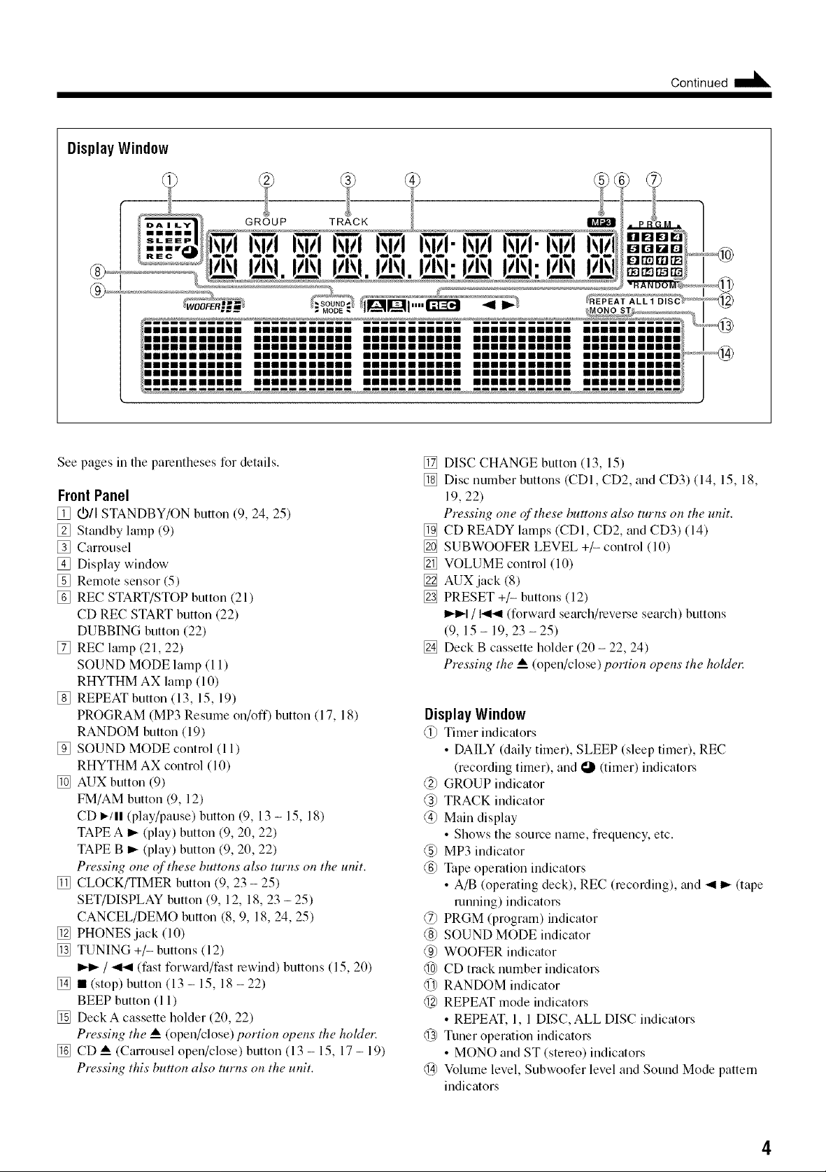
Display Window
®
Continued
See pages in the parentheses for details.
FrontPanel
[] VII STANDBY/ON button (9, 24, 25)
[] Sttmdby lamp (9)
[] Carrousel
[] Display window
[] Remote sensor (5)
[] REC START/STOP button (21)
CD REC START button (22)
DUBBING button (22)
[] REC lamp (21, 22)
SOUND MODE lamp (11)
RHYTHM AX lamp (10)
[] REPEAT button (13, 15, 19)
PROGRAM (MP3 Resume on/off) button (17, 18)
RANDOM button (19)
[] SOUND MODE control (11)
RHYTHM AX control (10)
[] AUK button (9)
FM/AM button (9, 12)
CD I_/II (play/pause) button (9, 13 - 15, 18)
TAPE A I_ (play) button (9, 20, 22)
TAPE B _ (play) button (9, 20, 22)
Pressing one qf these buttons also turns on the unit.
[] CLOCK/TIMER button (9, 23 - 25)
SET/DISPLAY button (9, 12, 18, 23 - 25)
CANCEL/DEMO button (8, 9, 18, 24, 25)
[] PHONES jack (10)
[] TUNING +/- buttons (12)
I_1_/ _ (fast forward/fast rewind) buttons (15, 20)
[] • (stop) button (13 - 15, 18 - 22)
BEEP button (11)
[] Deck A cassette holder (20, 22)
Pressing the A__(open/close) portion opens the holdel:
[] CD _ (Carrousel open/close) button (13 - 15, 17 - 19)
Pressing this button also turns on the unit.
[] DISC CHANGE button (13, 15)
[] Disc number buttons (CDI, CD2, trod CD3) (14, 15, 18,
19, 22)
Pressing one oflthese buttons also turns on the unit.
[] CD READY lamps (CDI, CD2, trod CD3) (14)
[] SUBWOOFER LEVEL +/- control (10)
[] VOLUME control (10)
[] AUX jack (8)
[] PRESET +/- buttons (12)
I_1 / 141_1(forward search/reverse search) buttons
(9, 15- 19,23-25)
[] Deck B cassette hokler (20 - 22, 24)
Pressing the _ (open/close) portion opens the holdel:
Display Window
@ Timer indicators
• DAILY (daily timer), SLEEP (sleep timer), REC
(recording timer), and O 0imer) indicators
@ GROUP indicmor
@ TRACK indicator
@ Main display
• Shows the source name, frequency, etc.
@ MP3 indicmor
@ Tape operation indicmors
• A/B (operming deck), REC (recording), and _1 _ (tape
running) indicators
@ PRGM (program) indicator
@ SOUND MODE indicmor
@ WOOFER indicmor
@ CD track number indicators
@ RANDOM indicmor
@ REPEAT mode indicators
• REPEAT, 1, 1 DISC, ALL DISC indicators
@ Tuner operation indicators
• MONO and ST (stereo) indicators
@ Volume level, Subwoofer level and Sound Mode pattern
indicators
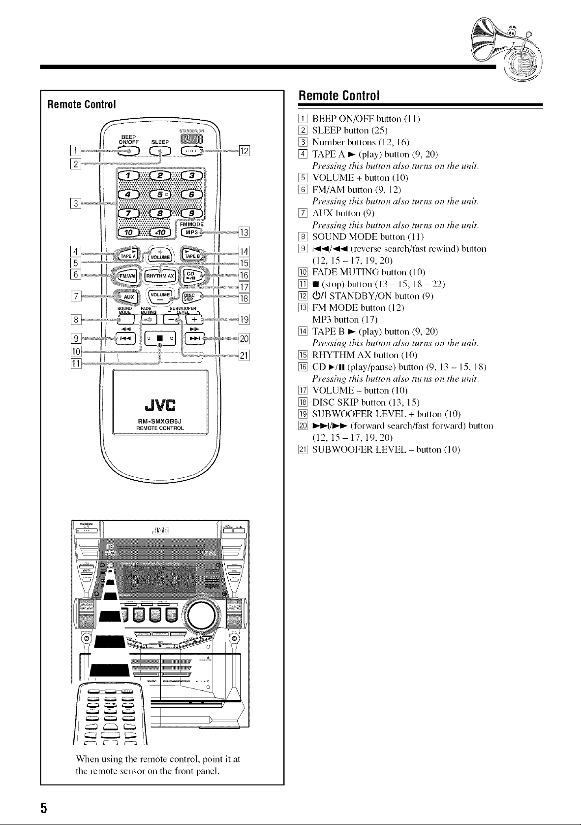
RemoteControl
BEEP
ON/OFF SLEEP
JVC
RM=SMXGB6J
REMOTE CONTROL
[]
RemoteControl
[] BEEP ON/OFF button (11)
[] SLEEP button (25)
[] Number buttons (12, 16)
[] TAPE A _ (play) button (9, 20)
Pressil_g this bumm also tuttis ol_the umt.
[] VOLUME + button (10)
[] FM/AM button (9, 12)
Pressb_g this buttot_ also turl*s ot_the umt.
[] RUN button (9)
Pressb_g this buttgm also turl_s o_ the umt.
[] SOUND MODE button (11)
[] I._1_1/_141(reverse search/fast rewind) button
(12, 15 - 17, 19, 20)
[] FADE MUTING button (10)
[] • (stop) button (13- 15, 18-22)
[] (._/I STANDBY/ON button (9)
[] FM MODE button (12)
MP3 button (17)
[] TAPE B _- (play) button (9, 20)
Pressb_g this butto_ also turl_s o_ the umt.
[] RHYTHM AX button (10)
[] CD I,-/11(play/pause) button (9, 13 - 15, 18)
Pressb_g this buttol_ also turl_s ol_the umt.
[] VOLUME - button (10)
[] DISC SKIP button (13, 15)
[] SUBWOOFER LEVEL + button (10)
[] I_=,-I/1_=,-(forward search/fast forward) button
(12, 15 - 17, 19, 20)
[] SUBWOOFER LEVEL - button (10)
When using the remote control, point it at
the remote sensor oil the front panel.
GettingStarted ooot,ouo ...=
Unpacking
After unpacking, check to be sure that you have all the
following items.
The number in the parentheses indicates the quantity of the
pieces supplied.
• AM loop antenna (1)
• FM antenna (1)
• Remote control (1)
• Batteries (2)
If any is missing, consult your dealer immediately.
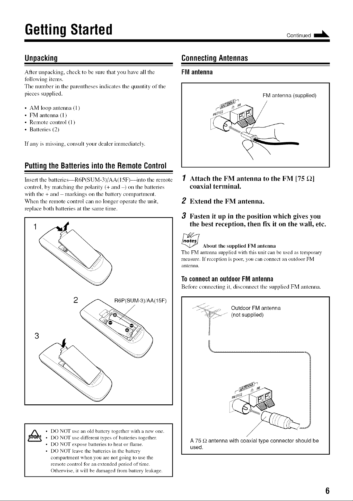
Putting the BatteriesintotheRemoteControl
Insert the batteries--R6P(SUM-3)/AA(l 5F)--into the remote
control, by matching the polarity (+ and -) on the batteries
with the + and - markings on the battery compartment.
When the remote control can no longer operate the unit,
replace both batteries at the same time.
ConnectingAntennas
FM antenna
FM antenna (supplied)
1 Attach the FM antenna to the FM [75 _]
coaxial terminal.
2 Extend the FM antenna.
3 Fasten it up in the position which gives you
the best reception, then fix it on the wall, etc.
_ About the supplied FM antenna
The FM antenna supplied with this unit carl be used as temporary
measure. If reception is poor, you carl connect an outdoor FM
antenrla.
ToconnectanoutdoorFIVIantenna
Before connecting it, disconnect the supplied FM antenna.
2
R6P(SUM-3)/AA(15F)
Outdoor FM antenna
(not supplied)
iJ
• DO NOT use an old battery together with a new one.
• DO NOT use different types of batteries together.
• DO NOT expose batteries to heat or flame.
• DO NOT leave tile batteries in tile battery
compartment when you are not going to use the
remote control for an extended period of time.
Otherwise, it will be damaged from battery leakage.
A 75 f2 antenna with coaxial type connector should be
used.
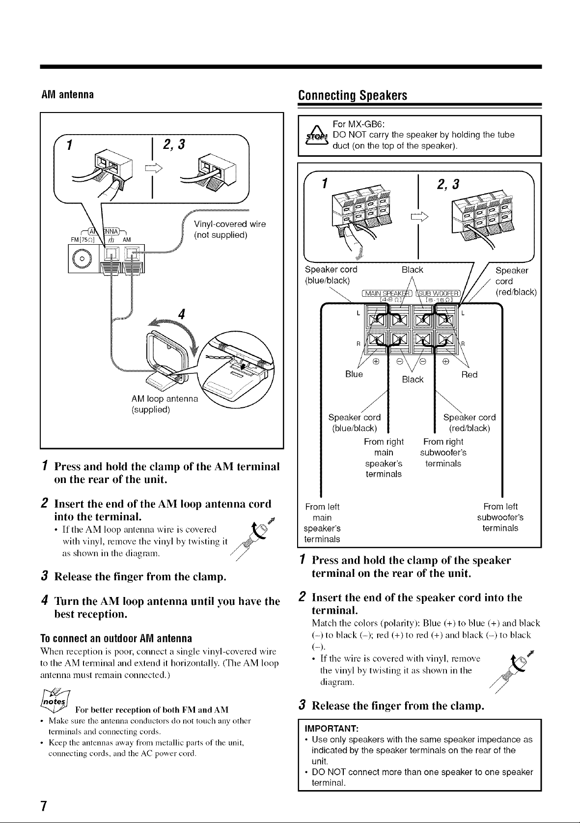
AM antenna
1
ConnectingSpeakers
For MX-GB6:
DO NOT carry the speaker by holding the tube
duct (on the top of the speaker).
Vinyl-covered wire
FM[75f)] AM
(not supplied)
4
AM loop antenna
(supplied)
1 Press and hold the clamp of the AM terminal
on the rear of the unit.
1
Speaker cord
(blue/black)
CMAIN
Speaker cord Speaker cord
(blue/black) (red/black)
From right From right
speaker's terminals
terminals
Black
Black
main subwoofer's
2,3
Speaker
cord
(red/black)
2 Insert the end of the AM loop antenna cord
into the terminal.
• If the AM loop tmtenna wire is covered
with vinyl, remove the vinyl by twisting it
as shown in the diagram. //
3 Release the finger from the clamp.
4 Turn the AM loop antenna until you have the
best reception.
Toconnectanoutdoor AMantenna
When reception is poor, connect a single vinyl-covered wire
to the AM terminal and extend it horizontally. (The AM loop
antenna must remain connected.)
_For better reception of both FM and AM
• Make sure the antenna conductors do not touch any other
terminals and connecting cords.
• Keep the antennas away from metallic parts of the unit,
connecting cords, and the AC power cord.
From left From left
main subwoofer's
speaker's terminals
terminals
1 Press and hold the clamp of the speaker
terminal on the rear of the unit.
2
Insert the end of the speaker cord into the
terminal.
Match the colors (polarity): Blue (+) to blue (+) _md black
(-) to black (-); red (+) to red (+) and black (-) to black
(-).
• If the wire is covered with vinyl, remove _/%J
the vinyl by twisting it as shown in the
diagram.
3 Release the finger from the clamp.
IMPORTANT:
• Use only speakers with the same speaker impedance as
indicated by the speaker terminals on the rear of the
unit.
• DO NOT connect more than one speaker to one speaker
terminal.
¢"
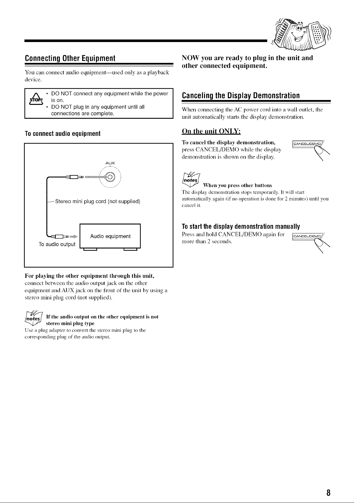
ConnectingOtherEquipment
You can cennect audio equipment--used enly as a playback
device.
NOW you are ready to plug in the unit and
other connected equipment.
• DO NOT connect any equipment while the power
is on.
• DO NOT plug in any equipment until all
connections are complete.
To connect audio equipment
/Stereo mini plug cord (not supplied)
'-_1_:=_ _#_ Audio equipment ]
To audio output
Canceling theDisplayDemonstration
When connecting the AC power cord into a wall outlet, the
unit automatically starts the display demonstration.
On the unit ONLY:
To cancel the display demonstration,
press CANCEL/DEMO while the display
demonstration is shown on the display.
AUX
_When you press other buttons
The display demonstration stops temporarily. It will start
automatically again (if no operation is done for 2 minutes) until you
cancel it.
Tostartthe displaydemonstrationmanually
Press trod held CANCEL/DEMO again fer
more than 2 seconds.
For playing the other equipment through this unit,
connect between the audio output jack on the other
equipment and AUX jack on the front of the unit by using a
stereo mini plug cord (not supplied).
_ f the audio output on the other equipment is not
Use a plug adapter to convert the stereo mini plug to the
corresponding plug of the audio output.
stereo mini plug type
 Loading...