

Page 1
ENGLISH
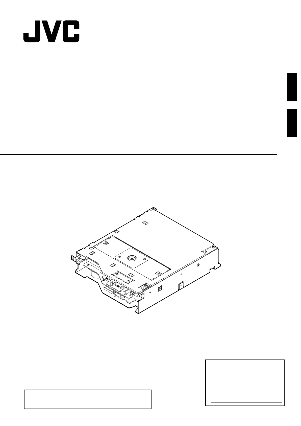
Blu-ray DRIVE
Blu-ray-LAUFWERK
MC-BL10U
DEUTSCH
INSTRUCTIONS
BEDIENUNGSALEITUNG
Thank you for purchasing the JVC MC-BL10U Blu-ray DRIVE.
Before you start operating this unit, please read the instructions
carefully in order to obtain the best possible performance.
For Customer Use:
Enter below the Model No. and Serial
No. which are located at the top of the
unit. Retain this information for future
reference.
Model No. MC-BL10U
Serial No.
LST0586-001A
Page 2
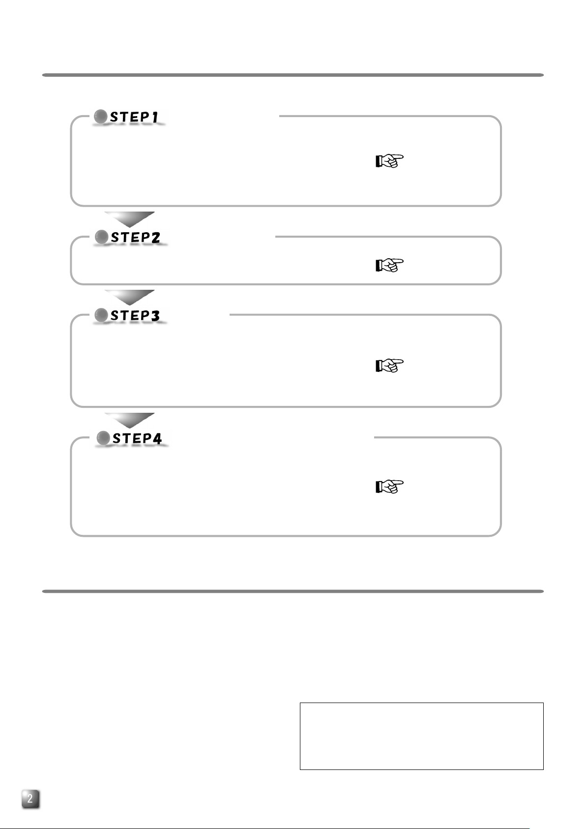
INSTALLATION FLOW
Follow the steps below for installation.
INSTALLATION
Install the MC-BL10U in the CD/DVD Library.
●
䡵 Procedure for Opening the Door of the CD/DVD Library
䡵 Procedure for Opening the Drive Storage Cover of the
CD/DVD Library
䡵 Procedure for Determining the Setup Position for the MC-BL10U
䡵 Procedure for Installing the MC-BL10U in the CD/DVD Library
CONNECTION
Connect the MC-BL10U to the CD/DVD Library.
●
䡵 Procedure for Connecting the Cables to the Back of the MC-BL10U
SETUP
Set the SCSI ID of the MC-BL10U and close the door of the CD/
●
DVD Library.
䡵 Procedure for Setting the DIP Switch
䡵 Procedure for Attaching the Drive Storage Cover of the CD/DVD
Library
䡵 Procedure for Closing the CD/DVD Library Door
Page E3, E4
Page E4, E5
Page E5
EXECUTION OF AUTOMATIC
DRIVE DETECTION MODE.
Execute the automatic drive detection mode and connect the host
●
computer.
䡵 Procedure for Executing the Automatic Drive Detection Mode of
the CD/DVD Library
䡵 Procedure for Connecting the CD/DVD Library to the Host Com-
puter
PRECAUTIONS BEFORE USE
The MC-BL10U is a Blu-ray drive designed for use with the
●
JVC MC-8100LU/8200LU/8600LU “CD/DVD Library”.
When installing this unit in a Library that is being used, please
●
read the instruction manual carefully.
The MC-BL10U cannot be operated on its own.
●
This unit cannot be used in combination with the following
●
models.
• CD-ROM Library : MC-1000 series/2000 series
• DVD-RAM Library: MC-7000 series
• CD/DVD Library : MC-8000 series
MC-BL10U cannot be used with drives other than MC-R434U.
●
For the compatible discs, see the Specifications on page E7.
●
●
1. DANGER: Invisible laser radiation will occur if the unit is
2. CAUTION: Do not open the top cover. There are no user
Page E6
In case of using MC-BL10U, MC-8200LU and MC-8600LU
have following limitation of the drive units due to the power
unit capacity.
* MC-8200LU/8600LU : max 5 drive units
e.g. MC-BL10U x 5
MC-BL10U x 1 and MC-R434U x 4
MC-BL10U x 0 and MC-R434U x 6
note : MC-8100LU doesn't have this limitation.
open due to a failed or defective interlocking device.
serviceable parts inside the unit; leave all servicing to
qualified service personnel.
E
Page 3

INSTALLATION
Install the MC-BL10U in the CD/DVD Library.
●
Before starting installation, be sure to turn both the
host computer and peripherals off.
For information related to the CD/DVD Library, refer
to the instruction manual for the CD/DVD Library.
Procedure for Opening the Drive Storage
Cover of the CD/DVD Library
Drive storage
section
Screw
Screw
ENGLISH
Procedure for Opening the Door of the
CD/DVD Library
Drive locking
screw mounting
hole
Drive storage
section
<With the MC-8100LU>
* The illustration shows the CD/DVD Library with the drive storage
cover removed for ease of description.
Drive storage
section
Drive storage
cover
<With the MC-8100LU>
Drive storage
section
Drive storage cover
Screw
<With the MC-8200LU>
1.
Remove the screws from the drive storage cover of the
CD/DVD Library.
2.
Remove the drive storage cover.
Drive locking
screw mounting
hole
<With the MC-8200LU>
1.
Select the [DOOR OPEN MODE] on the MENU screen of
the CD/DVD Library's LCD.
2.
Press and hold the "SELECT" switch for five seconds.
3.
Tu rn off the power of the CD/DVD Library when [THE DOOR
CAN BE OPENED] message is displayed on the LCD.
4.
Insert the key in the key cylinder located at the center of
the door to unlock and open the door.
Procedure for Determining the Setup
Position for MC-BL10U
Not Used
Drive No. 5
Drive No. 4
Drive No. 3
Drive No. 2
Drive No. 1
MC-8100LU drive storage section
<
1.
Install the drives to the drive slots No.1 through No.5 (No. 1
through No. 4 in the case of the MC-8100LU) sequentially.
䡵 It makes the work easy if the drives are installed from
the lowest number to the highest.
>
<
MC-8200LU drive storage section
Drive No. 4
Drive No. 3
Drive No. 2
Drive No. 1
>
E
Page 4

Interior
Drive 4
Drive 3
Drive 2
Drive 1
Library SCSI board
Not Used
Drive 5
Terminator
Internal SCSI (LVD) cable
68-pin external SCSI connector
To host computer (SE/LVD)
SE-LVD conversion board
Terminator
Internal SCSI (SE) cable
Procedure for Installing the MC-BL10U in
the CD/DVD Library
Sensor slit
1.
MC-BL10U
<MC-BL10U insertion direction>
CONNECTION
Connect the MC-BL10U to the CD/DVD Library.
●
Also refer to the instruction manual for the CD/
DVD Library.
Procedure for Connecting the Cables to
the Back of the MC-BL10U
MC-BL10U
2.
3.
Drive locking
screw
<MC-BL10U locking method>
1.
Insert the MC-BL10U from the rear of the CD/DVD Library
䡵 Be sure not to damage the sensor slit.
䡵 Make sure that the direction of the MC-BL10U is correct
when inserting it.
䡵 Be sure that the cables connected to the rear of the CD/
DVD Library are not caught or pinched when inserting
the MC-BL10U.
2.
Insert the MC-BL10U slowly until the screw installation hole
located on the side of the MC-BL10U and the screw installation hole located on the drive locking section are aligned.
3.
Screw in the provided Drive locking screw to the installation hole of the drive locking section.
䡵 Tighten the screw firmly.
䡵 If the drive locking screw is loose, the drive and/or Li-
brary may be damaged.
<MC-BL10U connection example>
3
Control cable
1.
SCSI cable
<MC-BL10U rear panel>
1.
Connect the power supply cable, control cable and SCSI
cable to the connectors at the rear of the MC-BL10U.
䡵 When using the MC-8100LU, the No. of the cable must
always correspond to the No. of the drive bay to which it
is being connected. If a cable with the wrong number is
connedted, it will lead to the equipment malfunctioning.
䡵 When using an MC8200LU/8600LU, connect the con-
trol cables which lead from the side of the drive bay where
the MC-BL10U is to be inserted.
䡵 Insert all connectors firmly.
䡵 SCSI cables are connected as a daisy chain connec-
tion. Each connector should be connected to the drive
positions as illustrated in the diagram.
• The SCSI cable, which is built into the MC-8100LU/
8200LU/8600LU standard models, terminates at the
location where the connection is physically terminated.
14p
DIP switch
4p
Power cable
E
Page 5

Library
<SE-LVD conversion board>
Internal SCSI (SE) cable
3.
4.
To each drive
2.
Connect the two LVD power cables (6P) to the SE-LVD
conversion board.
䡵 Both cables have identical connector types, so that ei-
ther cable can be connected to either connector on the
SE-LVD conversion board.
3.
Connect the internal SCSI (SE) cable (50P) to the SE-LVD
conversion board.
䡵 The other end of the internal SCSI (SE) cable is con-
nected to the library SCSI board in the library.
4.
Connect the internal SCSI (LVD) cable (68P) to the drives.
䡵 The other end of the internal SCSI (LVD) cable is con-
nected to the SE-LVD conversion board.
Internal SCSI cable (approx. 1.0 m)
<Interior of library>
50p
6p
2.
6p
68p
Internal SCSI (LVD) cable
LVD
power cable
Terminator
Drive 4
Drive 3
Drive 2
SETUP
Set the SCSI ID of the MC-BL10U and close the door
●
of the CD/DVD Library.
Always turn the power of the CD/DVD Library off when
the dip switches are moved.
For the details of the default factory settings, please
refer to the section "SCSI ID No. SETTING" of the
instructions from the CD/DVD Library.
Procedure for Setting the DIP Switch
RSV
ID 2
ID 1
ID 0
ON
1234
(Factory setting)
<MC-BL10U DIP switch settings on the rear panel>
1.
ID2, ID1, ID0: Setting of the SCSI ID No. of each drive.
䡵 When setting the SCSI ID No., use a number that is not
being used by other SCSI devices on the same bus.
䡵 The MC-BL10U should be used with one of the SCSI ID
No. 0 to 7. It cannot be used with No. 8 to 15.
䡵 RSV: Not available
<SCSI ID No. and DIP switch settings>
SCSI ID No.
0 OFF OFF OFF
1
*
2 OFF ON OFF
3 OFF ON ON
4ONOFF OFF
5ONOFF ON
6ONONOFF
7ONONON
ID2 ID1 ID0
OFF OFF ON
ON
OFF
Switch
: Factory setting.
*
Procedure for Attaching the Drive
Storage Cover of the CD/DVD Library
ENGLISH
To SE-LVD conversion board
<With the MC-8100LU>
Drive 1
Terminator
Library SCSI board
Internal SCSI
(SE) cable
1.
Secure the cover with the screws that were removed.
"Procedure for Opening the Drive Storage Cover of
the CD/DVD Library" on page 3.
Procedure for Closing the CD/DVD
Library Door
1.
Close the door and lock the key cylinder.
E
Page 6

EXECUTION OF AUTOMATIC DRIVE DETECTION MODE.
Execute the automatic drive detection mode of the
●
CD/DVD Library.
For the automatic drive detection mode, refer to the
instruction manual for the CD/DVD Library.
CAUTION
䡵 Be sure to close the drive storage cover and door of the
CD/DVD Library before turning it on.
䡵 After installing, adding, replacing or removing the drives,
be sure to execute the automatic drive detection mode.
Otherwise, a malfunction may result.
䡵 After installing, adding, removing or replacing the drives,
or changing the SCSI ID No., be sure to turn the host
computer off and then turn it on again.
Procedure for Executing the Automatic
Drive Detection Mode of the CD/DVD
1.
While holding the "8" key on the control panel, turn the
power of the CD/DVD Library on.
2.
When the LCD shows "DRIVE DETECTION COMPLETED,"
turn the power of the CD/DVD Library off.
3.
Tu rn the power on again and check the indication for the
drive type (DRIVE DISPLAY).
䡵 “BD DRIVE” will be displayed at the DRIVE DISPLAY on
the CD/DVD Library. If “UNKNOWN” is displayed, a cable
connection may not have been performed correctly. In
such a case, first turn off the power, then check the installation and connection again.
Library
Procedure for Connecting the CD/DVD
Library to the Host Computer
䡵 Use an Ultra160-compatible cable as the external SCSI cable.
To the host computer's
Host computer
External SCSI cable
(commercially available)
(Ultral60 compatibly)
CD/DVD library
䡵 The length of the SCSI cable built into the CD/DVD library is
1.0 meters.
䡵 When the built-in SCSI cable is used by connecting it to an
external SCSI cable, check the total length of the SCSI cable.
If it should exceed the length described below it might be the
cause of a malfunction.
1) Used for an LVD: The maximum external cable length
should be 10 meters.
2) Used for an SE (Narrow) unit: The maximum external cable
length should be as follows.
• SCSI-2, 20 Mbyte/s, SYNC : 1.5 meters (Up to a maxi-
• SCSI-2, 10 Mbyte/s, SYNC : 1.5 meters
• SCSI-2, ASYNC : 4.5 meters
䡵 Optimum performance may not be achieved depending on
the settings of the transmission rate, operation conditions,
etc., and could be the cause of a failure when writing on the
DVD-R or CD-R with high-speed.
䡵 Use an Ultra160-compatible cable as the external SCSI cable.
A malfunction may occur if any another type of cable is used.
䡵 Be sure to fasten the SCSI connector with suitable screws
after making a connection with an external SCSI cable.
host adapter for
controlling the CD/DVD
library
To the SCSI
connector
"SCSI-C"
mum of 2 drives)
E
Page 7

SPECIFICATIONS
䡵 Interface
Ultra 2 SCSI (80 Mbytes/s)
䡵 Data transfer rate
Sustained (when the maximum sync transfer rate of the host adapter is
set to 80 Mbytes/s)
BD-ROM 9 Mbytes/s (2X)
BD-R 9 Mbytes/s (2X)
BD-RE 9 Mbytes/s (2X)
DVD-RAM 4155 Kbytes/s (3X max.)
(Single-sided 4.7 GB or double-sided 9.4 GB)
DVD-R 11080 Kbytes/s (8X max.)
(Single-sided 4.7 GB or double-sided 9.4 GB)
DVD-ROM 11080 Kbytes/s (8X max.)
(Single Layer, Double Layer)
CD-ROM 4800 Kbytes/s (32X max.: CAV)
CD-R 4800 Kbytes/s (32X max.: CAV)
(when the maximum sync transfer rate of the host adapter is set to 80
Burst
Mbytes/s)
Max. 80 Mbytes/s (sync transfer)
䡵 Buffer capacity
8 Mbytes
䡵 Additional write count
(DVD-R for General, 4.7 GB)
500 times typical
(when a disc and a drive are combined)
15 times typical (when a disc and multiple drives are combined)
䡵 Dimensions (W x H x D)
172 mm x 45 mm x 220 mm
(Excluding protruding parts)
䡵 Applicable discs
BD-RE (Ver. 2.0)
Recommended discs:Single layer 25GB , Double layer 50GB
Matsushita Electric Corp.
BD-R (Ver. 1.0)
Recommended discs:Single layer 25GB , Double layer 50GB
Matsushita Electric Corp.
BD-ROM (Ver. 1.2)
DVD-R 4.7 GB
(Ver. 2.0 for General Use)
Recommended discs: Single-sided 4.7 GB
Hitachi Maxell Ltd.
DVD-ROM
DVD-RAM
(Ver. 2.1, 2X-3X, single-sided 4.7 GB or double-sided 9.4 GB)
Hitachi Maxell Ltd.
(Do not use 5X or faster speed DVD-RAM media)
CD-ROM (Mode-1, Mode-2, etc.)
CD-R
Taiyo Yuden Co., Ltd.
䡵 Writing Method
BD-RE Random Access
BD-R Sequential Recording
Random Recording
Sequential Recording with Logical Over Write
DVD-RAM Random Access
DVD-R Disc at Once, Incremental
CD-R Disc at Once
Session at Once
Tr ack at Once
Multi-Session
Fixed/Variable Packet Writing
ENGLISH
䡵 Mass
1.5 kg
䡵 Accessories
Instructions ....................................................................x 1
Drive locking screw ........................................................x 2
Caution sheet ................................................................. x 2
* Note 1: It is recommended to write and read the BD-RE,
BD-R, DVD-R, DVD-RAM and CD-R discs using the
drives of the same model. If drives of different
models are used in write and read, discs of certain manufacturers or production lots may not
manifest the full performance.
* Note 2: Only discs with a diameter of 120 mm are appli-
cable.
* Note 3: Use DVD-R and CD-R discs that match the opti-
mal writing speed. However, even if the appropriate discs are used, an adequate performance may
not be achieved depending on the disc manufacturer or production lot compatibility.
䡵 Design and specifications are subject to change without no-
tice.
E
Page 8

Blu-ray-LAUFWERK
MC-BL10U
DEUTSCH
BEDIENUNGSANLEITUNG
Page 9

INSTALLATIONSREIHENFOLGE
Bitte führen Sie erforderlichen Installationsschritte in der angezeigten Reihenfolge durch.
INSTALLATION
Installieren Sie das MC-BL10U in der CD/DVD-Bibliothek.
●
䡵 So öffnen Sie die Tür der CD/DVD-Bibliothek
䡵 So öffnen Sie die Einbaubuchtabdeckung der CD/DVD-Bibliothek
䡵 Bestimmen der Einbaubucht für das MC-BL10U
䡵 So installieren Sie das MC-BL10U in der CD/DVD-Bibliothek
ANSCHLÜSSE
Schließen Sie das MC-BL10U an die CD/DVD-Bibliothek an.
●
䡵 So schließen Sie die Kabel an die Rückseite von MC-BL10U an
EINRICHTEN
Stellen Sie die SCSI-ID-Nr. von MC-BL10U ein und schließen Sie
●
die Tür der CD/DVD-Bibliothek
䡵 So stellen Sie den DIP-Schalter ein
䡵 So bringen Sie die Einbaubuchtabdeckung der CD/DVD-Bibliothek
wieder an
䡵 So schließen Sie die Tür der CD/DVD-Bibliothek
Seite G3, G4
Seite G4, G5
Seite G5
DURCHFÜHREN DER AUTOMATISCHEN
LAUFWERKERFASSUNG
Führen Sie die automatische Laufwerkerfassung durch und
●
schließen Sie den Hostcomputer an.
䡵 So führen Sie die automatische Laufwerkerfassung für die CD/DVD-
Bibliothek durch.
䡵 So schließen Sie die CD/DVD-Bibliothek an den Hostcomputer an.
Seite G6
SICHERHEITSHINWEISE VOR DEM GEBRAUCH
Das MC-BL10U ist ein Blu-ray-Laufwerk, das für den Einsatz
●
mit der JVC MC-8100LU/8200LU/8600LU "CD/DVD
Bibliothek" entwickelt wurde.
Soll dieses Laufwerk in einer Bibliothek installiert werden, die
●
in Gebrauch ist, bitte unbedingt die Bedienungsanleitung
sorgfältig lesen.
Das MC-BL10U-Laufwerk kann nicht getrennt betrieben
●
werden.
Dieses Laufwerk kann nicht zusammen mit den folgenden
●
Modellen verwendet werden
• CD-ROM-Bibliothek : MC-1000 Serie/2000 Serie
• DVD-RAM-Bibliothek : MC-7000 Serie
• CD/DVD-Bidliothek : MC-8000U serie
MA-BL10U ist nur in Verbindung mit Laufwerk MC-R434U zu
●
verwenden.
Angaben zu kompatiblen Diskausführungen finden Sie in den
●
Technischen Daten auf Seite 8.
Bei der Verwendung des MC-BL10U haben MC-8200LU und
●
MC-8600LU aufgrund der Netzteilkapazität folgende
Einschränkungen bezüglich der Laufwerke.
* MC-8200LU/8600LU : maximal 5 Laufwerke
Beispiel : MC-BL10U x 5
MC-BL10U x 1 und MC-R434U x 4
MC-BL10U x 0 und MC-R434U x 6
Hinweis: Beim MC-8100LU gibt es diese Einschränkung nicht.
1. GEFAHR: Unsichtbare Laserstrahlung, falls die
Sicherheitsverriegelung beim Öffnen versagt oder
abgestellt wird.
2. VORSICHT: Die obere Abdeckung darf nicht entfernt
werden. Im Inneren der Einheit befinden sich keine Teile, die
vom Benutzer gewartet werden können. Wartungsarbeiten
geschultem Servicepersonal überlassen.
G
Page 10

Laufwerkbucht
Schraube
Einbaubuchtabdeckung
INSTALLATION
Installieren Sie das MC-BL10U in der CD/DVD-
●
Bibliothek.
Stellen Sie vor dem Einbau sicher, dass der Hostcomputer
und alle Peripheriegeräte ausgeschaltet sind.
Sonstige Angaben zum Einbau in die CD/DVDBibliothek entnehmen Sie bitte der zu der CD/DVDBibliothek gehörigen Bedienungsanleitung.
So öffnen Sie die Tür der CD/DVD-
Bibliothek
Montagebohrung
für Laufwerkmontageschraube
Laufwerkbucht
So öffnen Sie die Einbaubuchtabdeckung
der CD/DVD-Bibliothek
Laufwerkbucht
Schraube
Einbaubuchtabdeckung
<Für MC-8100LU>
Schraube
DEUTSCH
<Für MC-8100LU>
* In den Abbildungen wird die CD/DVD-Bibliothek zur erleichterten
Erläuterung ohne Einbaubuchtabdeckung gezeigt.
Laufwerkbucht
Montagebohrung
für Laufwerkmontageschraube
<Für MC-8200LU>
1.
Wählen Sie in dem auf der LCD-Anzeige der CD/DVDBibliothek dargestellten Menü den Eintrag [DOOR OPEN
MODE].
2.
Halten Sie den Schalter “SELECT” für fünf Sekunden
gedrückt.
3.
Schalten Sie die Stromversorgung der CD/DVD-Bibliothek
aus, sobald die Meldung [THE DOOR CAN BE OPENED]
auf der LCD-Anzeige erscheint.
4.
Zum Entriegeln und Öffnen der Tür stecken Sie den
Schlüssel in das in der Türmitte befindliche Zylinderschloss.
<Für MC-8200LU>
1.
Entfernen Sie die Schrauben von der Einbaubuchtabdeckung
der CD/DVD-Bibliothek.
2.
Nehmen Sie die Einbaubuchtabdeckung ab.
Bestimmen der Einbaubucht für das
MC-BL10U
Nicht belegt
Laufwerk Nr. 5
Laufwerk Nr. 4
Laufwerk Nr. 3
Laufwerk Nr. 2
Laufwerk Nr. 1
MC-8100LU Laufwerkbucht
<
1.
Insallieren Sie die Laufwerke nacheinander in den
Laufwerkbuchten Nr.1 bis Nr. 5 (Nr. 1 bis Nr. 4 im Fall von
MC-8100LU).
䡵 Wenn Sie bei der untersten Einbaubuchtnummer
beginnen, vereinfachen Sie sich die Einbauarbeit.
>
Laufwerk Nr. 4
Laufwerk Nr. 3
Laufwerk Nr. 2
Laufwerk Nr. 1
<
MC-8200LU Laufwerkbucht
>
G
Page 11

So installieren Sie das MC-BL10U in der
CD/DVD-Bibliothek
Sensorschlitz
1.
MC-BL10U
<Einbaurichtung von MC-BL10U>
MC-BL10U
2.
ANSCHLÜSSE
Schließen Sie das MC-BL10U an die CD/DVD-
●
Bibliothek an.
Siehe auch die zur CD/DVD-Bibliothek gehörige
Bedienungsanleitung.
So schließen Sie die Kabel an die
Rückseite von MC-BL10U an
Innenansicht
Nicht belegt
Laufwerk 5
Laufwerk 4
Laufwerk 3
Laufwerk 2
Terminator
Internes SCSI (LVD)-Kabel
externer 68-pol. SCSI-Anschluss
An Hostcomputer (SE/LVD)
SE-LVD-Karte
3.
Laufwerkmontageschraube
<Befestigung von MC-BL10U>
1.
Setzen Sie das MC-BL10U von der Rückseite der CD/DVDBibliothek ein.
䡵 Achten Sie darauf, dass hierbei der Sensorschlitz nicht
beschädigt wird.
䡵 Achten Sie auf die korrekte Einbaurichtung für das MC-
BL10U.
䡵 Achten Sie beim Einsetzen von MC-BL10U darauf, dass
an der Rückseite der CD/DVD-Bibliothek befindliche
Kabel nicht eingeklemmt werden.
2.
Schieben Sie das MC-BL10U langsam ein, bis die seitlich
am MC-BL10U befindliche Montagebohrung auf die
Montagebohrung der Laufwerkbucht ausgerichtet ist.
3.
Befestigen Sie die mitgelieferte Montageschraube in der
Montagebohrung der Laufwerkbucht .
䡵 Ziehen Sie die Schraube einwandfrei fest.
䡵 Bei einer lose angebrachten Montageschraube kann es
zu Schäden am Laufwerk und/oder der Bibliothek
kommen.
Laufwerk 1
Bibliothek-SCSI-Karte
<Anschlussbeispiel MC-BL10U>
1.
SCSI-Kabel
<Rückseite von MC-BL10U>
1.
Schließen Sie das Netzkabel, Steuerkabel und SCSI-Kabel
an die entsprechenden Anschlüsse auf der Rückseite des
MC-BL10U an.
䡵 Bei Benutzung des MC-8100LU muß die Kabel-Nr. immer
der Nr. des Laufwerkeinschubs entsprechen, an dem es
angeschlossen ist. Wenn Laufwerke mit dem falschen
Einschub verbunden werden, kommt es zu
Fehlfunktionen.
䡵 Bei der Verwendung von Modellausführung MC-8200LU/
8600LU müssen die Steuerkabel verwendet werden, die
seitlich in das Einschubfach geführt werden, in dem MCBL10U installiert werden soll.
䡵 Überprüfen Sie die Stecker auf einwandfreien Sitz.
䡵 Die SCSI-Kabel müssen in Reihe angeschlossen
werden. Der Anschluss für die einzelnen Einbaubuchten
wird im Diagramm dargestellt.
• Der Abschluss des in den Standardmodellen MC8100LU/8200LU/8600LU eingebauten SCSI-Kabels
stimmt mit dem physischen Kabelabschluss überein.
Terminator
Internes SCSI (SE)-Kabel
3
Steuerkabel
14p
DIP-Schalter
4p
Spannungsversorgung
G
Page 12

EINRICHTEN
Stellen Sie die SCSI-ID-Nr. für das MC-BL10U ein
●
und schließen Sie die Tür der CD/DVD-Bibliothek.
Sie müssen unbedingt die Stromversorgung der CD/
DVD-Bibliothek ausschalten, bevor Sie mit der
Einstellung der DIP-Schalter beginnen.
Angaben zur Grundeinstellung ab Werk siehe den
Abschnitt “SCSI ID Nr. SETTING” in der zur CD/DVDBibliothek gehörigen Bedienungsanleitung.
< SE-LVD-Karte >
Internes SCSI (SE)-Kabel
3.
4.
An jedes Laufwerk
2.
Schließen Sie die beiden LVD-Stromversorgungskabel (6polig) an die SE-LVD-Karte an.
䡵 Beide Kabel sind mit identischen Steckerausführungen
ausgerüstet und können dementsprechend beliebig an
einen der Anschlüsse der SE/LVD-Karte angebracht
werden.
3.
Schließen Sie das interne SCSI (SE)-Kabel (50-polig) an
die SE-LVD-Karte an.
䡵 Das andere Ende des internen SCSI (SE)-Kabels ist an
die Bibliothek-SCSI-Karte in der Bibliothek
anzuschließen.
4.
Schließen Sie das interne SCSI (LVD)-Kabel (68-polig) an
die Laufwerke an.
䡵 Das andere Ende des internen SCSI (LVD)-Kabels ist
an die SE-LVD-Karte anzuschließen.
< Innenansicht der Bibliothek >
50p
6p
LVD-
2.
6p
68p
Internes SCSI (LVD)-Kabel
Internes SCSI-Kabel (ca. 1,0 m)
Stromversorgungskabel
Terminator
Laufwerk 4
Laufwerk 3
Laufwerk 2
So stellen Sie den DIP-Schalter ein
RSV
ID 2
ID 1
ID 0
ON
1234
(Grundeinstellung ab Werk)
<MC-BL10U DIP-Schalter-Einstellung an der Rückseite>
1.
ID2, ID1, ID0: Einstellung der SCSI-ID-Nr. für jedes Laufwerk.
䡵 Achten Sie darauf, keine SCSI-ID Nr. zu verwenden, die
bereits einem anderen SCSI-Peripheriegerät des
gleichen Busses zugewiesen wurde.
䡵 Dem MC-BL10U muss eine der SCSI ID-Nummern 0
bis 7 zugewiesen werden. Die Nummern 8 bis 15 sind
ungeeignet.
䡵 RSV: Nicht verfügbar.
<SCSI-ID-Nr.- und DIP-Schalter-Einstellungen>
SCSI ID No.
0 OFF OFF OFF
1
*
2 OFF ON OFF
3 OFF ON ON
4ONOFF OFF
5ONOFF ON
6ONONOFF
7ONONON
ID2 ID1 ID0
OFF OFF ON
ON
OFF
Schalter
: Grundeinstellung ab Werk.
*
So bringen Sie die Einbaubuchtabdeckung
der CD/DVD-Bibliothek wieder an
DEUTSCH
An SE-LVD-Karte
<With the MC-8100LU>
Laufwerk 1
Terminator
Bibliothek-SCSI-Karte
Internes SCSI
(SE)-Kabel
1.
Bringen Sie die Einbaubuchtabdeckung mit den zuvor
entfernten Schrauben an.
“So öffnen Sie die Tür der CD/DVD-Bibliothek” auf Seite 3
So schließen Sie die Tür der CD/DVD-
Bibliothek
1.
Schließen Sie die Tür ab.
G
Page 13

DURCHFÜHREN DER
AUTOMATISCHEN LAUFWERKERFASSUNG.
Führen Sie die automatische Laufwerkerfassung für
●
die CD/DVD-Bibliothek durch.
Angaben zum automatischen Lauwerksserkennungsmodus finden Sie in der zur CD/DVDBibliothek gehörigen Bedienungsanleitung.
So schließen Sie die CD/DVD-Bibliothek
an den Hostcomputer an
䡵 Als externes SCSI-Kabel muss eine 160-kompatible
Ausführung verwendet werden.
VORSICHT
䡵 Vergewissern Sie sich vor dem Einschalten der CD/DVD-
Bibliothek, dass die Einbaubuchtabdeckung befestigt
und die Tür der CD/DVD-Bibliothek geschlossen ist.
䡵 Wenn Laufwerke installiert, hinzugefügt, ausgetauscht
oder entfernt wurden, muss unbedingt eine automatische
Laufwerkerfassung durchgeführt werden. Andernfalls
kann es zu Betriebsstörungen kommen.
䡵 Wenn Laufwerke installiert, hinzugefügt, ausgetauscht
oder entfernt oder SCSI-ID-Nummern geändert wurden,
muss der Hostcomputer unbedingt aus- und erneut
eingeschaltet werden
So führen Sie die automatische Laufwerkerfassung für
die CD/DVD-Bibliothek durch
1.
Während Sie die Taste “8” auf der Bedientafel gedrückt
halten, schalten Sie die CD/DVD-Bibliothek ein.
2.
Wenn auf der LCD-Anzeige die Meldung “DRIVE DETECTION COMPLETED” erscheint, schalten Sie die CD/DVDBibliothek aus.
3.
Schalten Sie nochmals ein und überprüfen Sie die Anzeige
für die Laufwerksausführung (DRIVE DISPLAY).
䡵 “BD DRIVE” wird für DRIVE DISPLAY an der CD/DVD-
Bibliothek angezeigt. Falls “UNKNOWN” angezeigt wird,
kann ein fehlerhafter Kabelanschluss vorliegen. In
diesem Fall zuerst ausschalten und anschließend den
Einbau und die Anschlüsse nochmals überprüfen.
An den Hostadapter
Hostcomputer
Externes SCSI-Kabel
(im Fachhandel erhältlich)
(Ultra160-kompatible)
CD/DVD-Bibliothek
䡵 Die Länge des in der CD/DVD-Bibliothek eingebauten SCSI-
Kabels beträgt 1,0 m.
䡵 Wird das interne SCSI-Kabel mit einem externen SCSI-Kabel
verbunden, muss die zulässige Gesamtlänge der SCSIKabelverbindung berücksichtigt werden. Falls die zulässige
nachfolgend angegebene Gesamtlänge überschritten wird,
kann es zu Betriebsstörungen kommen.
1) Für LVD: Die maximal zulässige Länge des externen Kabels
beträgt 10 m.
2) Für SE (Eng): Für die maximal zulässige Länge des
externen Kabels gelten die folgenden Beschränkungen:
• SCSI-2, 20 Mbyte/s SYNC : 1,5 Meter (Max. 2 Laufwerke)
• SCSI-2, 10 Mbyte/s SYNC : 1,5 Meter
• SCSI-2, ASYNC : 4,5 Meter
䡵 Die maximal verfügbare Leistung kann ggf. in Abhängigkeit
von der Einstellung der Transferrate, den Betriebsbedingungen
etc., nicht erzielt werden. In diesem Fall kann es zu
Betriebsstörungen kommen, wenn Daten in hoher
Geschwindigkeit auf die DVD-R oder CD-R geschrieben
werden.
䡵 Als externes Kabel muss eine Ultra160-kompatible
Ausführung verwendet werden. Bei Verwendung einer anderen
Kabelausführung kann es zu Betriebsstörungen kommen.
䡵 Bei Anschluss eines externen SCSI-Kabels muss der
Steckverbinder mit geeigneten Schrauben befestigt werden.
des Hostcomputers zur
Steuerung der
CD/DVD-Bibliothek
An den SCSIAnschluss,
“SCSI-C”
G
Page 14

TECHNISCHE DATEN
䡵 Schnittstelle
Ultra 2 SCSI (80 Mbytes/Sek.)
䡵 Datentransferrate
Unterbrechungsfrei (wenn der Hostadapter mit der maximalen Sync-
Tr ansferrate von 20 Mbytes/Sek. arbeitet)
BD-ROM 9 Mbytes/Sek. (2X)
BD-R 9 Mbytes/Sek. (2X)
BD-RE 9 Mbytes/Sek. (2X)
DVD-RAM 4155 Kbytes/Sek. (3X max.)
(Einseitig 4,7 GB oder beidseitig 9,4 GB)
DVD-R 11080 Kbytes/Sek. (6X max.)
(Einseitig 4,7 GB oder beidseitig 9,4 GB)
DVD-ROM 11080 Kbytes/Sek.
(Einzelschicht, Beidseitig)
CD-ROM 4800 Kbytes/Sek. (32X max.: CAV)
CD-R 4800 Kbytes/Sek. (32X max.: CAV)
(wenn der Hostadapter mit der maximalen Sync-Transferrate von 80
Burst
Mbytes/Sek. arbeitet)
Max. 80 Mbytes/Sek. (synchroner Datentransfer)
䡵 Zwischenspeicher
8 Mbytes
䡵 Zählung zusätzlicher Schreibvorgänge
(DVD-R für allgemeine Anwendungen, 4,7 GB)
Typisch 500 Vorgänge
(eine Disk und ein Laufwerk kombiniert)
Typisch15 Vorgänge (eine Disk und mehrere Laufwerke kombiniert)
䡵 Abmessungen (B x H x T)
172 mm x 45 mm x 220 mm
(Vorspringende Teilenicht eingeschlossen)
䡵 Masse
1,5 kg
䡵 Zubehör
Bedienungsanleitung .....................................................x 1
Laufwerkmontageschraube ...........................................x 2
Warnhinweisblatt............................................................x 2
䡵 Geeignete Disks
BD-RE (Ver. 2.0)
Empfohlene Disks: Einseitig 25 GB, Beidseitig 50 GB
Matsushita Electric Corp.
BD-R (Ver. 1.0)
Empfohlene Disks: Einseitig 25 GB, Beidseitig 50 GB
Matsushita Electric Corp.
BD-ROM (Ver. 1.2)
DVD-R 4.7 GB
(Ver. 2.0 für allgemeinen Gebrauch)
Empfohlene Disks: Einseitig 4,7 GB
Hitachi Maxell Ltd.
DVD-ROM
DVD-RAM
(Ver. 2.1, 2X-3X, einseitig 4,7 GB oder beidseitig 9,4 GB)
Hitachi Maxell Ltd.
(Verwenden Sie nicht 5X oder schnellere Geschwindgkeit
DVD-RAM Medium)
CD-ROM
(Modus 1, Modus 2 etc.)
CD-R
Taiyo Yuden Co., Ltd.
䡵 Schreibmethode
BD-RE Direktzugriff
BD-R Sequentielle Aufnahme
Zufallsaufnahme
Sequentielle Aufnahme mit Logical Over Write
DVD-RAM Direktzugriff
DVD-R Disc-At-Once-Modus, Inkrementell
CD-R Disc-At-Once-Modus
Session-at-Once-Verfahren
Tr ack-At-Once-Verfahren
Multisession
Fixed/Variable Packet Writing
* Hinweis 1: Es wird empfohlen, für BD-RE, BD-R, DVD-R,
DVD-RAM und CD-R Disks stets sowohl im
Schreib- als auch im Lesebetrieb jeweils
dieselbe Laufwerk-Modellausführung zu
verwenden. Werden für den Schreib- und
Lesebetrieb unterschiedliche LaufwerkModellausführungen eingesetzt, kann für Disks
bestimmter Hersteller und/oder Bauserien ggf.
nicht die volle Leistung erzielt werden.
* Hinweis 2: Es dürfen ausschließlich Disks mit einem
Durchmesser von 120 mm verwendet werden.
* Hinweis 3:
Verwenden Sie DVD-R- und CD-R-Disks, die für die
optimale Schreibgeschwindigkeit ausgelegt sind.
Bitte beachten Sie, dass selbst bei Verwendung
geeigneter Disks je nach Disk-Hersteller und infolge
von Produktionsschwankungen die maximal
verfügbare Leistung ggf. nicht erreicht werden kann.
䡵 Änderungen der Konstruktion und der technischen Daten
jederzeit ohne Vorankündigung vorbehalten.
DEUTSCH
G
Page 15

MC-BL10 Blu-ray DRIVE
© 2007 Victor Company of Japan, Limited
LST0586-001A
 Loading...