

Page 1
R
SERVICE MANUAL
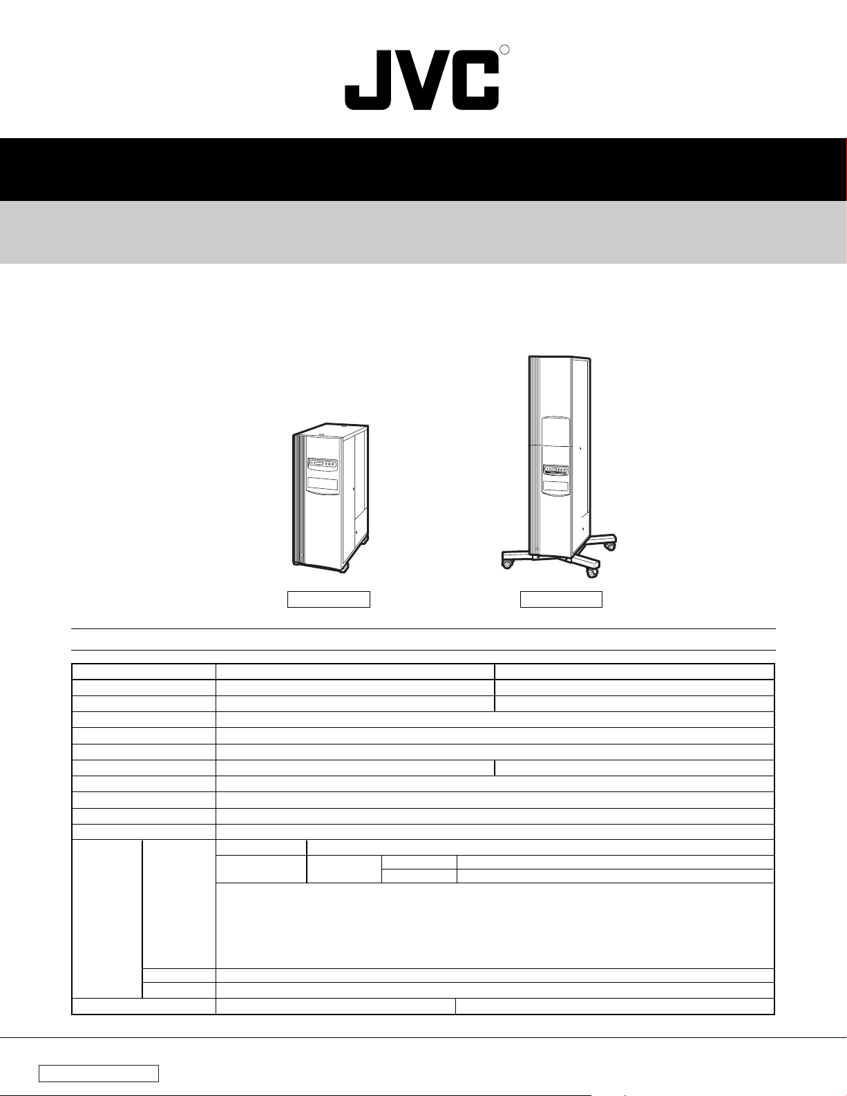
CD/DVD LIBRARY
MC-8200LU/MC-8600LU
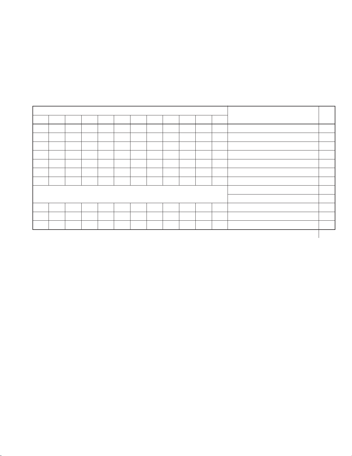
SPECIFICATIONS
Item
Number of stored discs
Number of magazines
Operating environment
Rated power voltage
Rated power frequency
Rated current
Power consumption
Interface
Drive slots rack bays
Media size
Applicable
options
Weight
Drives
Carrier
Magazine
MC-8200LU
MC-8200LU
200
4
Temperature: 5°C to 35°C (41°F to 95°F) (Note 1) Humidity: 10% to 80% (no condensation)
AC 120 V to 240 V
50 Hz/60 Hz
2.4 A to 1.4 A (max. value), 1.4 A to 0.8 A (6 Drives are loaded)
140 W (Reference value, 6 DVD-RAM drives are loaded)
68-pin external SCSI connector
6
12 cm discs
Available drives
DVD-RAM/R
drive
• The relevant specifications for the drives can be found in the appropriate instruction manual.
• Concerning the Availability/Compatibility of the drives that are not listed, please contact your dealer
or nearest JVC service centre.
• The production of a particular drive may be discontinued without prior notice. Therefore,
a replacement drive may be changed to a different model.
• JVC does not provide a warranty in the case of software not functioning correctly as a result of a
drive being replaced or added.
Single-sided / Double-sided compatible disc carrier: MC-CF10U
Magazine set: MC-M25U (B)
(Excluding the discs and optional equipment)
58kg
MC-R434U Write/Read
Read
DVD-RAM (Ver. 2.1), DVD-R (for General), CD-R, CD-RW
DVD-ROM, CD-ROM
104kg
MC-8600LU
MC-8600LU
600
12
3.2 A to 1.8 A (max. value), 1.4 A to 0.8 A (6 Drives are loaded)
Compatible discs
(Excluding the discs and optional equipment)
100% recycled paper
COPYRIGHT © 2003 VICTOR COMPANY OF JAPAN, LTD.
No. HM003
Dec. 2003
Page 2
Important Safety Precautions
Connector
Metal sleeve
Prior to shipment from the factory, JVC products are strictly inspected to conform with the recognized product safety and electrical codes
of the countries in which they are to be sold. However, in order to maintain such compliance, it is equally important to implement the
following precautions when a set is being serviced.
Precautions during Servicing
1. Locations requiring special caution are denoted by labels and
inscriptions on the cabinet, chassis and certain parts of the
product. When performing service, be sure to read and comply with these and other cautionary notices appearing in the
operation and service manuals.
2. Parts identified by the
critical for safety.
Replace only with specified part numbers.
Note: Parts in this category also include those specified to com-
ply with X-ray emission standards for products using
cathode ray tubes and those specified for compliance
with various regulations regarding spurious radiation
emission.
3. Fuse replacement caution notice.
Caution for continued protection against fire hazard.
Replace only with same type and rated fuse(s) as specified.
4. Use specified internal wiring. Note especially:
1) Wires covered with PVC tubing
2) Double insulated wires
3) High voltage leads
5. Use specified insulating materials for hazardous live parts.
Note especially:
1) Insulation Tape 3) Spacers 5) Barrier
2) PVC tubing 4) Insulation sheets for transistors
6. When replacing AC primary side components (transformers,
power cords, noise blocking capacitors, etc.) wrap ends of
wires securely about the terminals before soldering.
symbol and shaded ( ) parts are
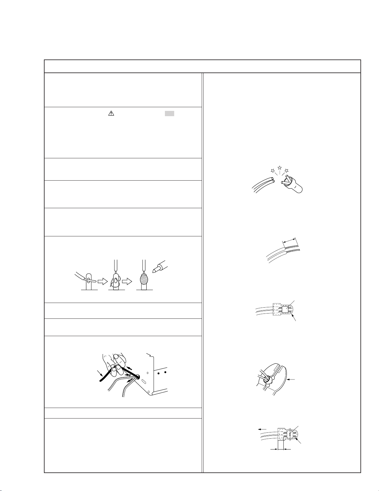
12. Crimp type wire connector
In such cases as when replacing the power transformer in sets
where the connections between the power cord and power
transformer primary lead wires are performed using crimp type
connectors, if replacing the connectors is unavoidable, in order to prevent safety hazards, perform carefully and precisely
according to the following steps.
1) Connector part number : E03830-001
2) Required tool : Connector crimping tool of the proper type
which will not damage insulated parts.
3) Replacement procedure
(1) Remove the old connector by cutting the wires at a point
close to the connector.
Important : Do not reuse a connector (discard it).
cut close to connector
Fig.3
(2) Strip about 15 mm of the insulation from the ends of
the wires. If the wires are stranded, twist the strands to
avoid frayed conductors.
15 mm
7. Observe that wires do not contact heat producing parts
8. Check that replaced wires do not contact sharp edged or
9. When a power cord has been replaced, check that 10-15 kg of
10. Also check areas surrounding repaired locations.
11. Products using cathode ray tubes (CRTs)
Fig.1
(heatsinks, oxide metal film resistors, fusible resistors, etc.)
pointed parts.
force in any direction will not loosen it.
Power cord
Fig.2
In regard to such products, the cathode ray tubes themselves,
the high voltage circuits, and related circuits are specified for
compliance with recognized codes pertaining to X-ray emission.
Consequently, when servicing these products, replace the cathode ray tubes and other parts with only the specified parts.
Under no circumstances attempt to modify these circuits.
Unauthorized modification can increase the high voltage value
and cause X-ray emission from the cathode ray tube.
Fig.4
(3) Align the lengths of the wires to be connected. Insert
the wires fully into the connector.
Fig.5
(4) As shown in Fig.6, use the crimping tool to crimp the
metal sleeve at the center position. Be sure to crimp fully
to the complete closure of the tool.
1.25
2.0
5.5
Fig.6
(5) Check the four points noted in Fig.7.
Not easily pulled free
Wire insulation recessed
more than 4 mm
Fig.7
Crimping tool
Crimped at approx. center
of metal sleeve
Conductors extended
1
Page 3
p
Safety Check after Servicing
Examine the area surrounding the repaired location for damage or deterioration. Observe that screws, parts and wires have been
returned to original positions, Afterwards, perform the following tests and confirm the specified values in order to verify compliance with safety standards.
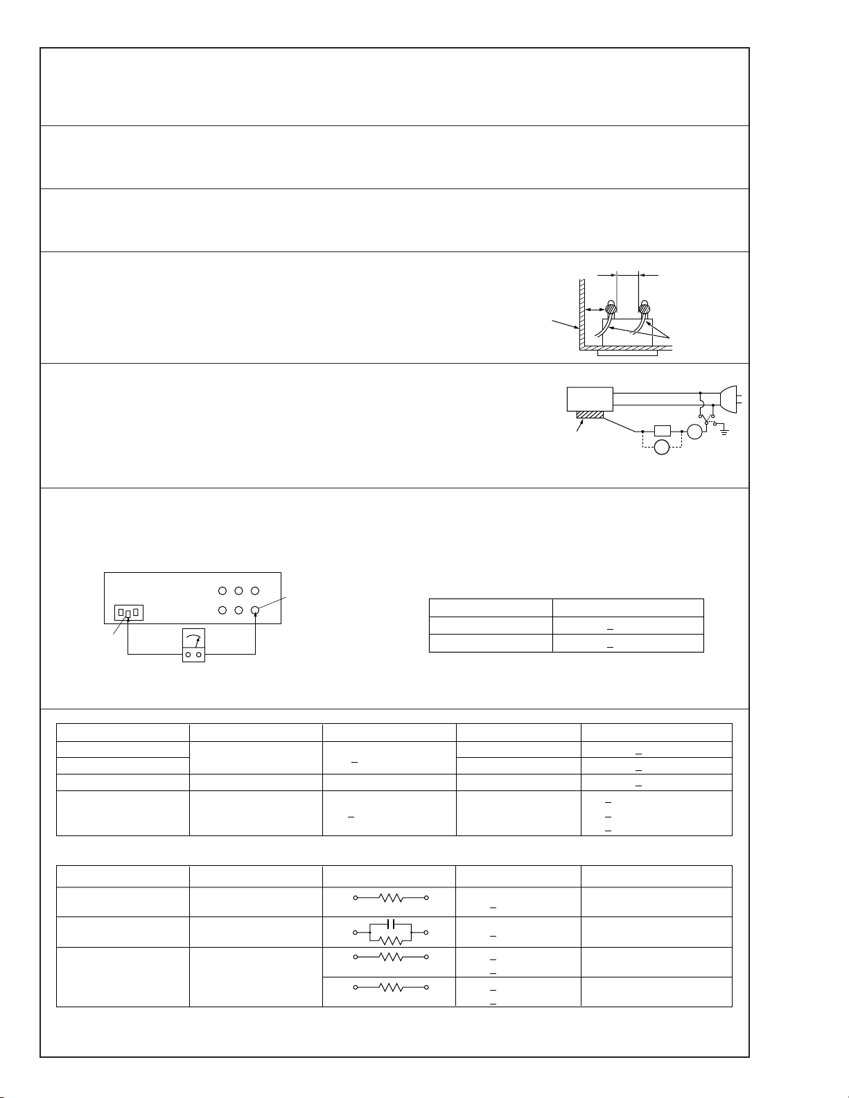
1. Insulation resistance test
Confirm the specified insulation resistance or greater between power cord plug prongs and
externally exposed parts of the set (RF terminals, antenna terminals, video and audio input
and output terminals, microphone jacks, earphone jacks, etc.). See table 1 below.
2. Dielectric strength test
Confirm specified dielectric strength or greater between power cord plug prongs and exposed
accessible parts of the set (RF terminals, antenna terminals, video and audio input and output
terminals, microphone jacks, earphone jacks, etc.). See table 1 below.
3. Clearance distance
When replacing primary circuit components, confirm specified clearance distance (d), (d’) between soldered terminals, and between terminals and surrounding metallic parts. See table 1
below.
Chassis
Fig. 8
4. Leakage current test
Confirm specified or lower leakage current between earth ground/power cord plug prongs
and externally exposed accessible parts (RF terminals, antenna terminals, video and audio
input and output terminals, microphone jacks, earphone jacks, etc.).
Measuring Method : (Power ON)
Insert load Z between earth ground/power cord plug prongs and externally exposed accessible parts. Use an AC voltmeter to measure across both terminals of load Z. See figure 9 and
following table 2.
5. Grounding (Class 1 model only)
Confirm specified or lower grounding impedance between earth pin in AC inlet and externally exposed accessible parts (Video in,
Video out, Audio in, Audio out or Fixing screw etc.).
Measuring Method:
Connect milli ohm meter between earth pin in AC inlet and exposed accessible parts. See figure 10 and grounding specifications.
AC inlet
Earth pin
Exposed accessible part
Grounding Specifications
Region
USA & Canada
Europe & Australia
Externally
exposed
accessible
Grounding Impedance (Z)
d
d'
art
≤
Z 0.1 ohm
≤
Z 0.5 ohm
Power cord,
primary wire
Z
V
Fig. 9
ab
c
A
Milli ohm meter
Fig. 10
AC Line Voltage
100 V
100 to 240 V
110 to 130 V
110 to 130 V
200 to 240 V
100 V
110 to 130 V
110 to 130 V
220 to 240 V
Note: These tables are unofficial and for reference only. Be sure to confirm the precise values for your particular country and locality.
Region
Japan R 1 MΩ/500 V DC
USA & Canada
Europe & Australia R 10 MΩ/500 V DC
Region Load Z
Japan
USA & Canada
Europe & Australia
Table 2 Leakage current specifications for each region
Insulation Resistance (R)
≤
–
≤
Table 1 Specifications for each region
1 kΩ
0.15 µF
1.5 kΩ
2 kΩ
50 kΩ
Dielectric Strength
AC 1 kV 1 minute
AC 1.5 kV 1 miute
AC 900 V 1 minute
AC 3 kV 1 minute
AC 1.5 kV 1 minute
i1 mA rms Exposed accessible parts
i 0.5 mA rms
i 0.7 mA peak
i2 mA dc
i 0.7 mA peak
i2 mA dc
≤
≤
≤
≤
≤
≤
(Class 2)
(Class 1)
Clearance Distance (d), (d')
≤
d, d' 3 mm
≤
d, d' 4 mm
≤
d, d' 3.2 mm
≤
d 4 mm
≤
d' 8 mm (Power cord)
≤
d' 6 mm (Primary wire)
a, b, cLeakage Current (i)AC Line Voltage
Exposed accessible parts
Antenna earth terminals
Other terminals
2
Page 4
SECTION 1
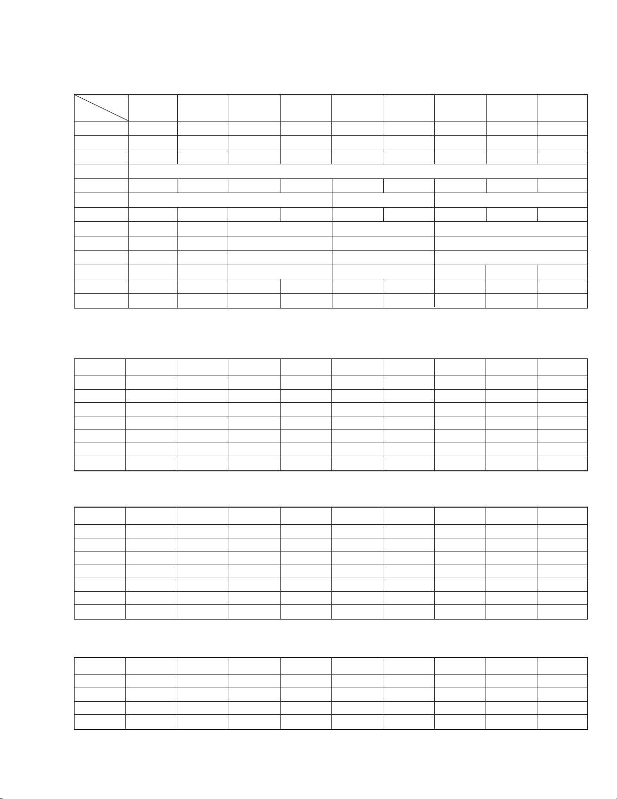
CIRCUIT BOARD COMPATIBILITY
Model
Unit Name
SCSI PCB ASS'Y
CHASSIS PCB ASS'Y
CARRIER MECHA ASS'Y
MAIL SLOT ASS'Y
U/D MOTOR ASS'Y
MAGAZINE SET
POWER UNIT ASS'Y
CD-ROM DRIVE
CD-R DRIVE — — MC-R18/MC-R14/MC-R12 — — MC-R18/MC-R14/MC-R12
DVD-ROM DRIVE
DVD-RAM DRIVE
DVD-R DRIVE — — MC-R421 MC-R421 — — — — —
DVD-RAM/R DRIVE
MC-8100LU
MC81-SCSI MC82-SCSI MC81-SCSI MC82-SCSI MC71-SCSI MC72-SCSI MC21-SCSI MC22-SCSI MC12-SCSI
MC81-CHAS MC82-CHAS MC81-CHAS MC82-CHAS MC71-CHAS MC72-CHAS MC21-CHAS MC22-CHAS MC12-CHAS
MC21-CARR MC22-CARR MC21-CARR MC22-CARR MC21-CARR MC22-CARR MC21-CARR MC22-CARR MC12-CARR
MC21-UD-M MC12-UD-M MC21-UD-M MC12-UD-M MC21-UD-M MC12-UD-M MC21-UD-M MC12-UD-M MC12-UD-M
QALD141-001
—— MC-D32/MC-D18 — — MC-D32/MC-D18
——MC-D307/MC-D104/MC-D207 — — MC-D307/MC-D104/MC-D207
——MC-R400/MC-R200 MC-R200 — — —
MC-R434 MC-R434 MC-R433 MC-R433 — — — — —
MC-8200LU/8600LU
MC-M25 (B) MC-M25 MC-M15
QAL0538-001 QAL0141-001 QAL0112-001 QAL0141-001 QAL0112-001 QAL0141-001 QAL0112-001 MC12-POWR
MC-8100 MC-8200/8600 MC-7100 MC-7200/7600 MC-2100 MC-1200/1600
MC12-MAIL
MC-2200/2200P
MC-2600/2600P
*1: The CARRIER MECHA ASS’Y has upward compatibility. (The MC21-CARR can be used with all models.)
SCSI PCB Compatibility Table R: Usable. ^: Usable by replacing ROM. ×: Unusable.
MC81-SCSI
MC82-SCSI
MC71-SCSI
MC72-SCSI
MC21-SCSI
MC22-SCSI
MC12-SCSI
MC-8100LU
R × R × ^ × ^ ××
× R × R × ^ × ^ ×
^ × ^ × R × ^ ××
× ^ × ^ × R × ^ ×
^ × ^ × ^ × R ××
× ^ × ^ × ^ × R Ч
ЧЧЧЧЧЧЧЧR
MC-8200LU/8600LU
MC-8100
MC-8200/8600
MC-7100
MC-7200/7600
MC-2100
MC-2200/2600 MC-1200/1600
CHASSIS PCB Compatibility Table R: Usable. ^: Usable by replacing ROM. ×: Unusable.
MC81-CHAS
MC82-CHAS
MC71-CHAS
MC72-CHAS
MC21-CHAS
MC22-CHAS
MC12-CHAS
MC-8100LU
R × R × ^ × ^ ××
× R × R ЧЧЧЧЧ
^ × ^ × R × ^ ××
ЧЧЧЧЧR × ^^
^ × ^ × ^ × R ××
ЧЧЧЧЧ^ × R^
ЧЧЧЧЧ^ × ^R
MC-8200LU/8600LU
MC-8100
MC-8200/8600
MC-7100
MC-7200/7600
MC-2100
MC-2200/2600 MC-1200/1600
CARRIER MECHA ASS’Y Compatibility Table R: Usable. ×: Unusable.
MC21-MCRR
MC22-MCRR
MC12-MCRR
MC-8100LU
RRRRRRRRR
× R × R × R × RR
ЧЧЧЧЧЧЧЧR
MC-8200LU/8600LU
MC-8100
MC-8200/8600
MC-7100
MC-7200/7600
MC-2100
MC-2200/2600 MC-1200/1600
MC-CF10 RRRR ЧЧЧЧЧ
1-1
Page 5

SECTION 2
PRODUCT SPECIFIC SERVICE ITEMS
2.1 Removal of Major Parts
2.1.1 Replacement of Fuses and Batteries
1. Fuses
Note:
Perform fuse replacements correctly.
Never use a fuse other than that specified by the manufacturer (same model number or its equivalent).
There are four fuses on the chassis PCB and one fuse on the SCSI PCB. When replacing a fuse, be sure to use one having the
specified parts number. For the parts number, refer to “5. PCB Ass’y Parts List”.
Chassis PCB : F120, F900, F400, F500
SCSI PCB : F2
2. Batteries
Note:
If the battery is not replaced correctly, it could cause an explosion.
Never use a battery other than one specified by the manufacturer (same model number or its equivalent). After replacement,
dispose of the expired battery according to the instructions of the manufacturer.
There are two batteries; one on the chassis PCB and the other on the SCSI PCB. When replacing a battery, be sure to use one having
the specified parts number. For the parts number, refer to “5. PCB Ass’y Parts List”.
Chassis PCB : BT300
SCSI PCB : BT1
2-1
Page 6
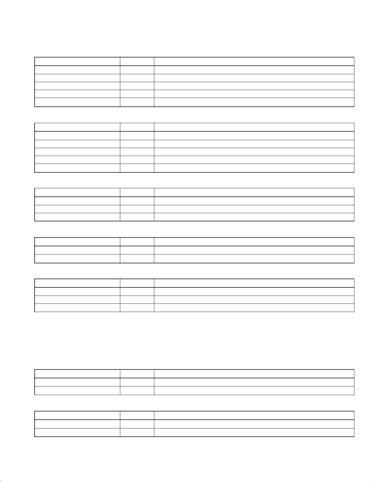
2.1.2 Opening/Closing the Door and Panel Removal
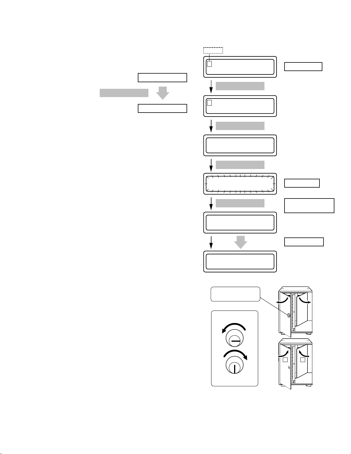
Opening the Door
<In normal condition>
When the power of the main unit is OFF, first turn it to ON.
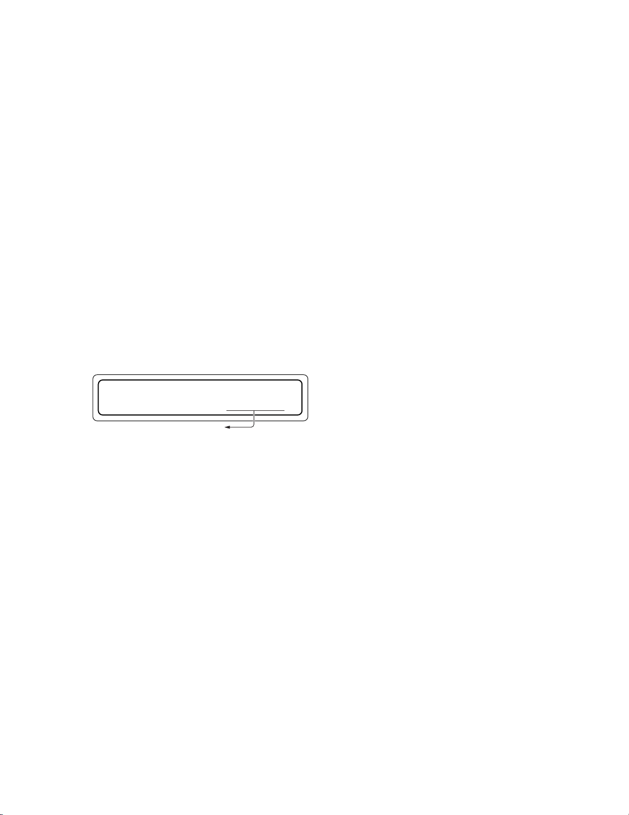
1. Press the MODE switch on the control panel to display the
MENU display.
NORMAL display
MODE switch
Cursor
1 . NORMAL DISPLAY
2 . ERROR DISPLAY
SELECT switch
MENU display
MENU display
2. Use the SELECT switch to move the cursor to “5. DOOR
OPEN MODE” and select with the MODE switch.
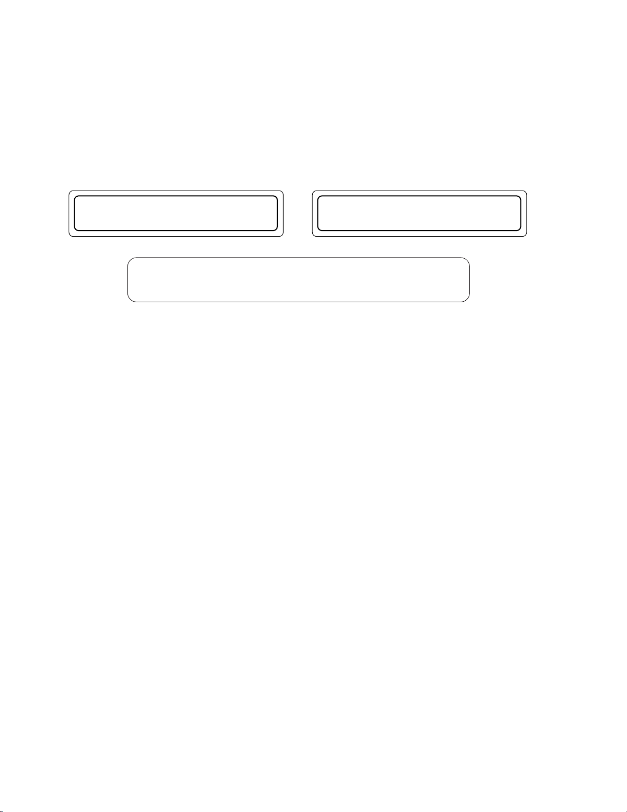
3. When the SELECT switch is pressed, the LCD display starts
blinking. Hold down the switch for more than 5 seconds,
the unit enters the door open mode.
4. When the door open mode operation completes, the message “YOU MAY OPEN THE DOOR” is displayed accompanied by a click sound.
In this condition, when the MODE switch is pressed without
opening the door, the “NORMAL display” (normal operation
status) resumes.
5 . DOOR OPEN MODE
6 . ID No. SET MODE
MODE switch
PUSH SELECT SW
TO OPEN THE DOOR
SELECT switch
PUSH SELECT SW
TO OPEN THE DOOR
SELECT switch
EXECUTING DOOR
OPEN PROCESS
YOU MAY
OPEN THE DOOR
Display blinks
Hold down for more
than 5 sec.
Wait for a while
5. Turn the power of the main unit to OFF.
Door open/close key
cylinder (lock key)
Unlocked
6. Insert the key and turn it counterclockwise (by 90°) to re-
(release)
lease the lock. Now the doors are opened toward you.
7. When closing the door, first close the [L] door then close the
[R] door.
L R
While holding the door gently, turn the key clockwise (by 90°)
to lock it, then pull out the key.
Locked
(lock)
<When trouble occurs>
When the power is not turned on or when electrical or mechanical trouble occurs, the unit will not enter the door open mode with the
above operations, and inserting the key cannot open the door. In this case, proceed in the following manner to open the door.
1. Turn the power of the main unit to OFF.
2. Insert a pin having a diameter of approx. 2 mm (or extended spike or clip, etc.) into the emergency hole to release the key lock. With
this, you can turn the key to perform the door opening operation.
2-2
Page 7
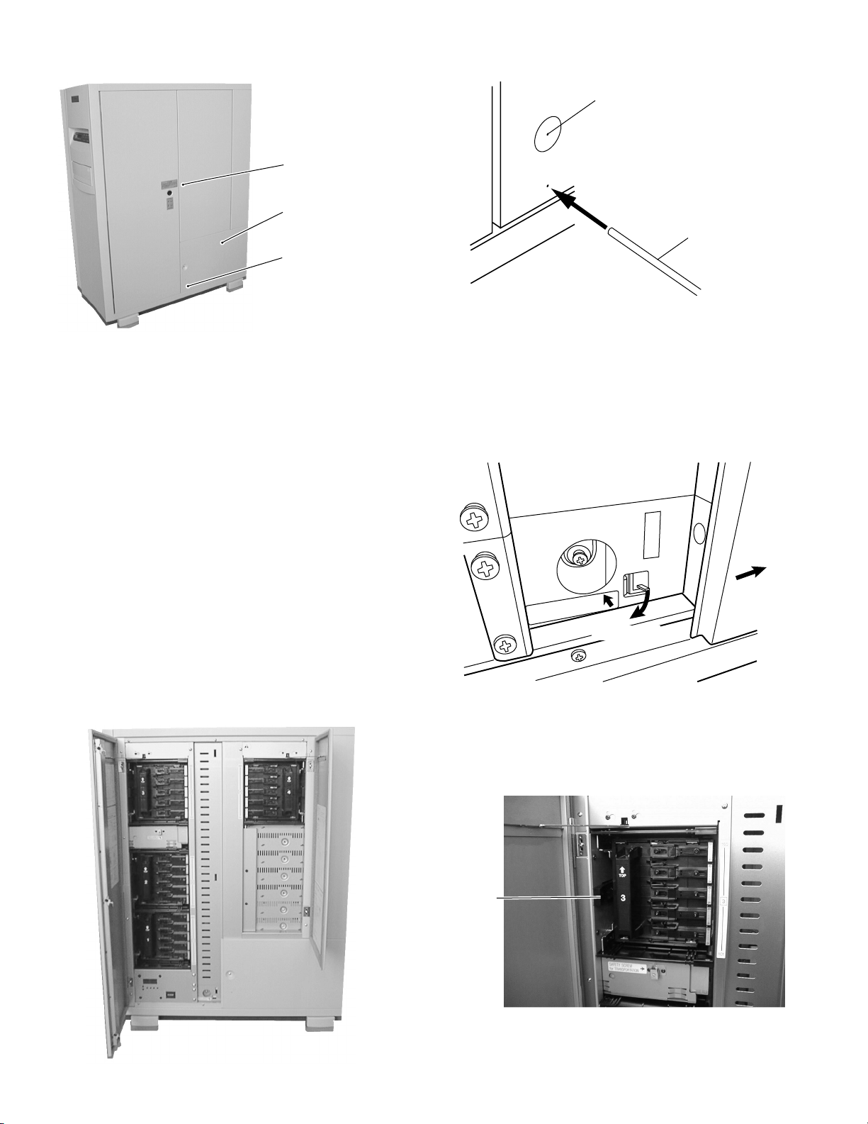
Key Cylinder
Panel
Emergency Hole
Panel mounting
screw
Pin (2 mm dia.)
Removing the Panel
<In normal condition>
Turn the power OFF in standby mode, insert a pin into the emergency hole on the panel, and open the door using the key. Then
remove the screw enabling the panel to be removed by sliding
it to the right.
2.1.3 Removing the Magazine
1. Open the door. (Refer to 2.1.2.)
Removing the Panel
<When trouble occurs>
When trouble occurs with the carrier stopped at the lower section, remove the panel while release the lock by pressing down
the lever shown in the diagram.
Panel
Slide
SAFETY SCREW for
TRANSPORTATION
Release lock
2. Pull the release lever which locks the magazine toward you.
The magazine is slightly protruded toward the front.
2-3
Release Lever
Page 8
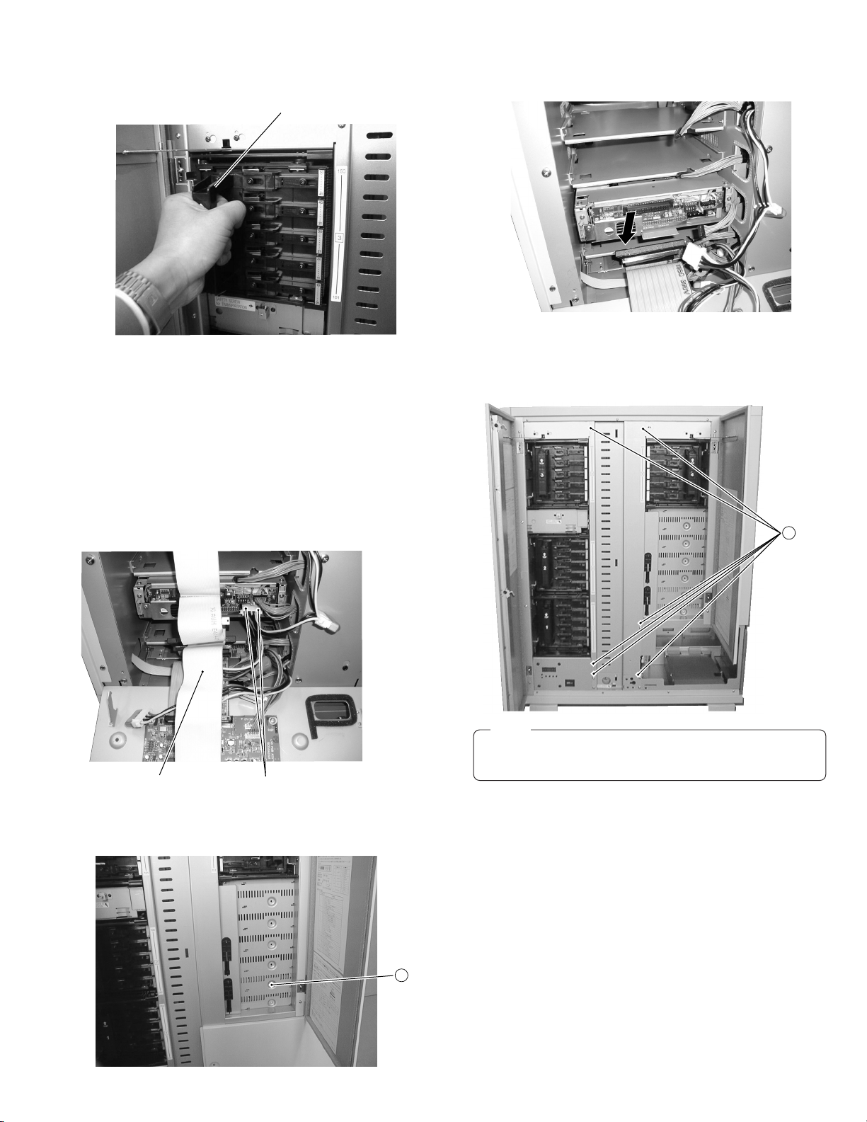
3. Grasp the grip to remove the magazine toward you. 6. Remove the drive from the rear.
2
6 screws
Grip
2.1.5 Removing the Center Panel
4. When loading the magazine, insert the magazine gently until
it clicks.
2.1.4 Removing the Drive
1. Open the door. (Refer to 2.1.2.)
2. Remove the panel. (Refer to 2.1.2.)
3. Remove the six screws
to remove the center panel.
2
1. Open the door. (Refer to 2.1.2.)
2. Remove the rear panel (DH). (Refer to 2.1.8.)
3. Disconnect the two connector cables from the drive.
4. Disconnect all the SCSI cables from all the drives and the
SCSI PCB. (When removing the drive in the uppermost slot
among the currently mounted drives, disconnect the cable
connected to the uppermost drive only.)
Photo shows situation when removing the Drive 2
SCSI cable
5. Remove the screw
Connector cable
located on the side of the drive (door
1
panel side).
Photo shows situation when removing the Drive 2
Note:
Center panel must be removed when removing the carrier mechanism.
1
2-4
Page 9
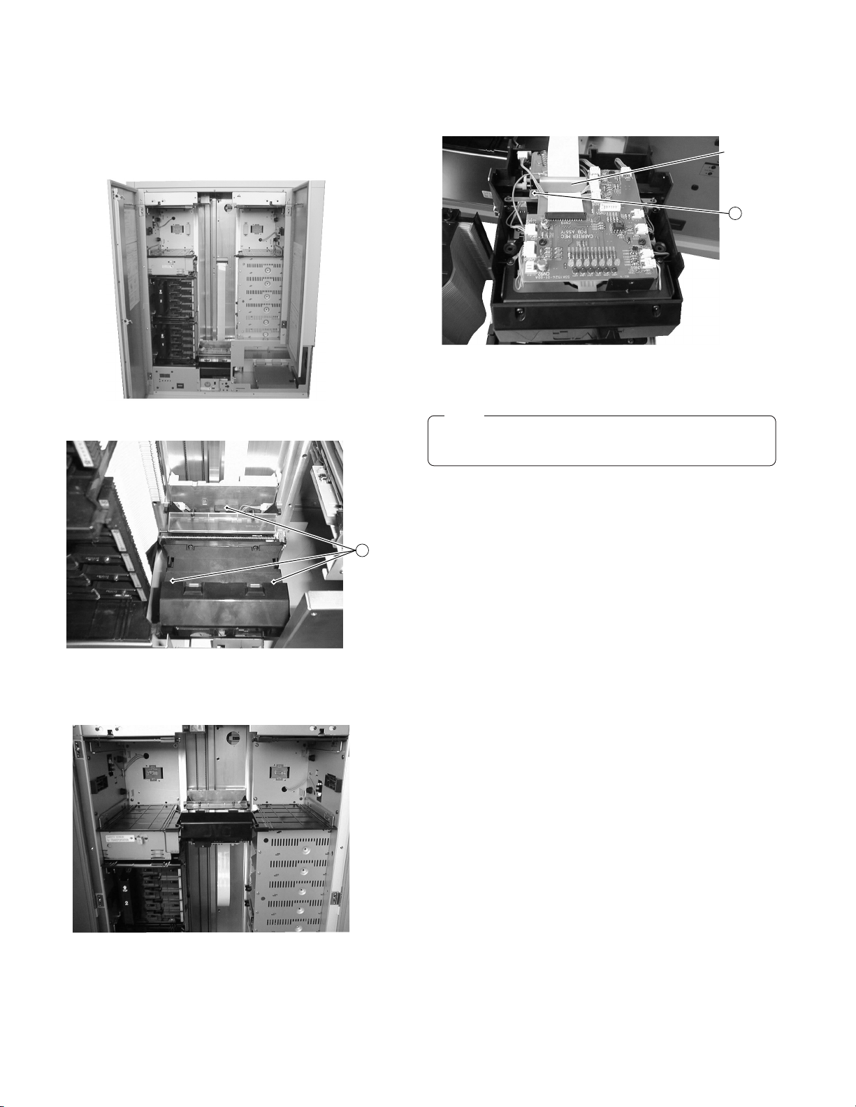
2.1.6 Removing the Carrier Mechanism
1. Open the door. (Refer to 2.1.2.)
2. Remove the center panel. (Refer to 2.1.5.)
3. Remove the #3 and #4 magazines. (Refer to 2.1.3.)
For the MC-8600U, remove the #3 and #4 magazines in the
same way.
6. Remove the carrier mechanism upward.
7. Turn the carrier mechanism upside down, and remove the
screws
retaining the flat cable mounting bracket.
4
Bracket
4
8. Release the flat cable connector lock and disconnect the flat
cable to remove the carrier mechanism.
4. Remove the three screws 3.
3
5. While holding the lower section of the carrier mechanism,
rotate the shaft of the U/D motor by hand to shift the carrier
mechanism to the #3/#4 magazine position.
Note:
Pay attention not to damage the lock of the flat cable connector .
2-5
Page 10
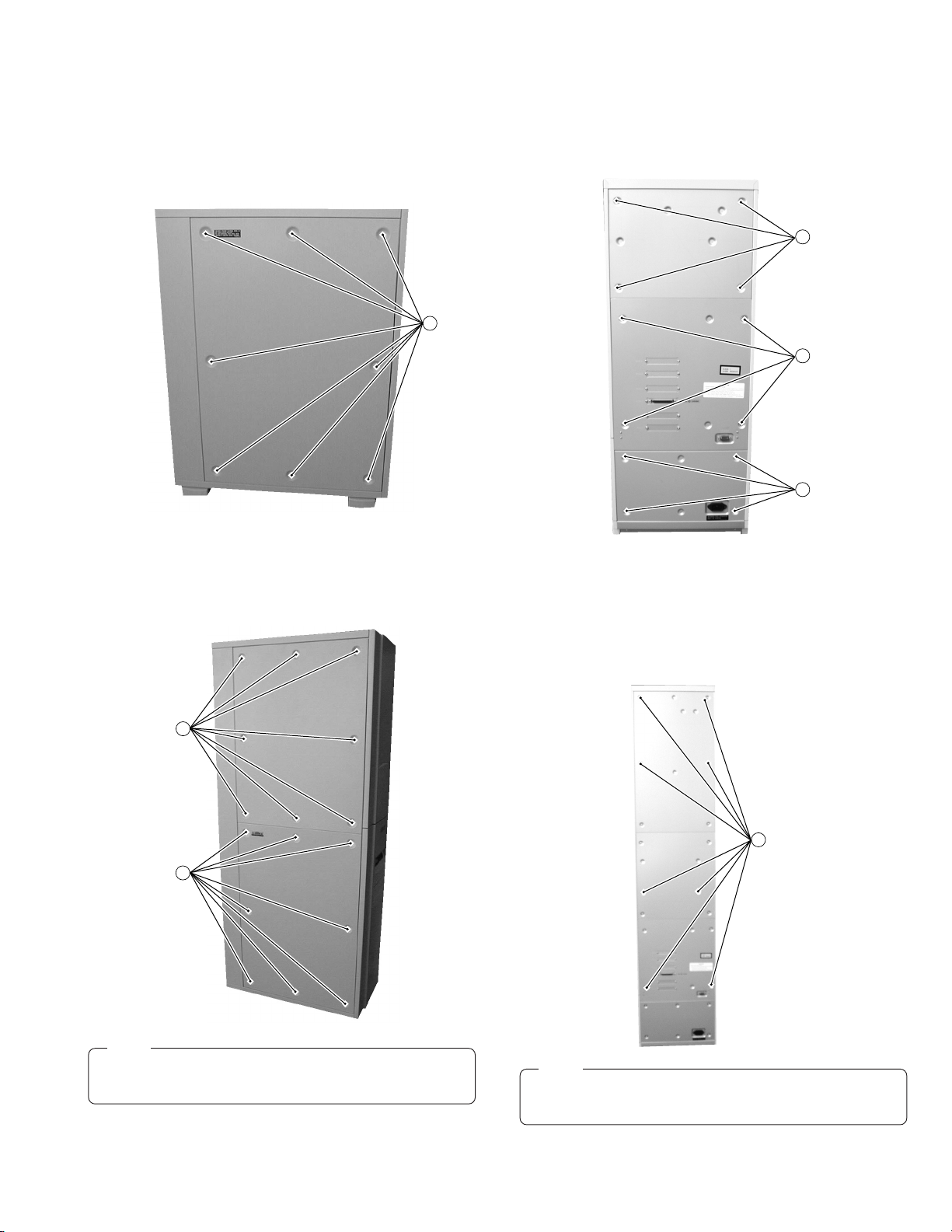
2.1.7 Removing the Side Panel
7
(T6)
8 screws
<MC-8200U>
1. Remove the eight screws 6 to remove the side panel.
When removing the side panel, unscrew while holding the
side panel with your hands. (To prevent the panel from dropping.)
2.1.8 Removing the Rear Panel
<MC-8200U>
1. Remove the three rear panels (T), (DH) and (B) by removing
the four screws 7 for each.
(T)
7
4 screws
6
<MC-8600U>
1. Remove the 16 screws
to remove the side panels.
6
When removing the side panel, unscrew while holding the
side panel by hand. Pay special attention to the upper side
panel. (in order to prevent the panel from being dropped.)
6
(DH)
7
4 screws
(B)
7
4 screws
<MC-8600U>
1. In the same way as MC-8200U, remove the two rear panels
(DH) and (B).
2. Remove the eight screws
to remove the upper rear panel
7
(T6).
6
Note:
When removing the U/D motor and magazine sensor PCB,
remove the upper side panel.
Note:
When removing the power supply unit, chassis PCB or
SCSI PCB, you don’t have to remove the rear panels.
2-6
Page 11
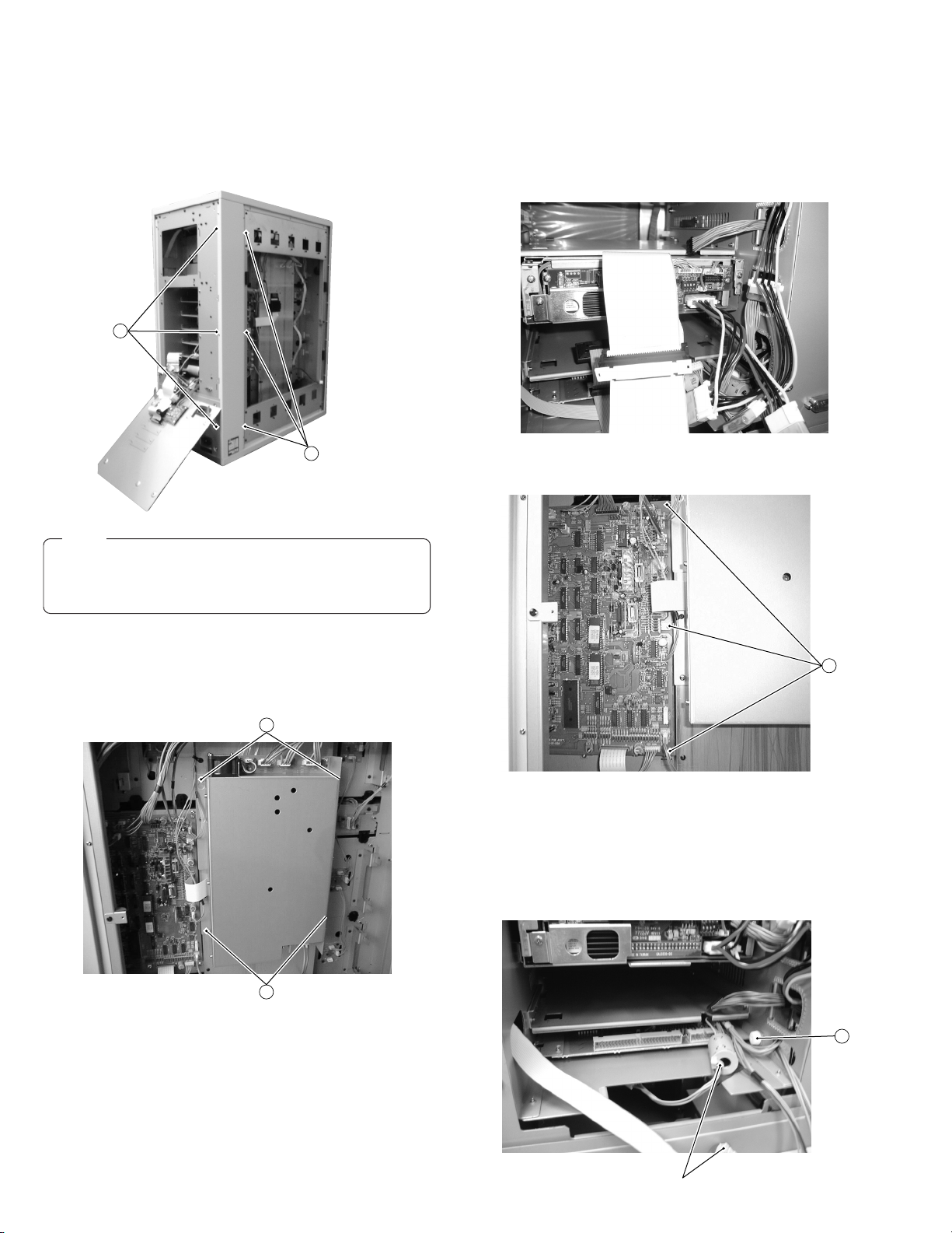
2.1.9 Removing the Exterior Side Panel
1. Remove the rear panel. (Refer to 2.1.8.)
2. Remove the side panel. (Refer to 2.1.7.)
3. Remove the six screws 8 (ten screws for MC-8600U), to
remove the exterior side panel.
8
3 screws
2.1.11 Removing the Chassis PCB
1. Remove the rear panel (DH). (Refer to 2.1.8.)
2. Remove the side panel. (Refer to 2.1.7.)
3. Remove the chassis PCB and connector cables from the drive
at the drive side. (Leave the cables connected to the drive
power supply as they are.)
8
3 screws
Note:
When removing the power supply unit, chassis PCB or
SCSI PCB, there is no need to remove the exterior side
panel.
2.1.10 Removing the Power Supply Unit
1. Remove the side panel. (Refer to 2.1.7.)
2. Disconnect the connector cables connected to the power supply unit.
10
4. Disconnect the connector cables from the chassis PCB.
5. Remove the three screws
!
.
11
6. Slide the chassis PCB toward the left and pull it out from the
right side.
2.1.12 Removing the SCSI PCB
1. Remove the rear panel (DH). (Refer to 2.1.8.)
2. Disconnect the two connector cables and all the SCSI cables connected to the SCSI PCB and the drives.
3. Remove the two screws 9.
4. Slightly loosen the two screws
supply unit by sliding it upward.
2-7
9
, and remove the power
0
12
Connector cable
Page 12
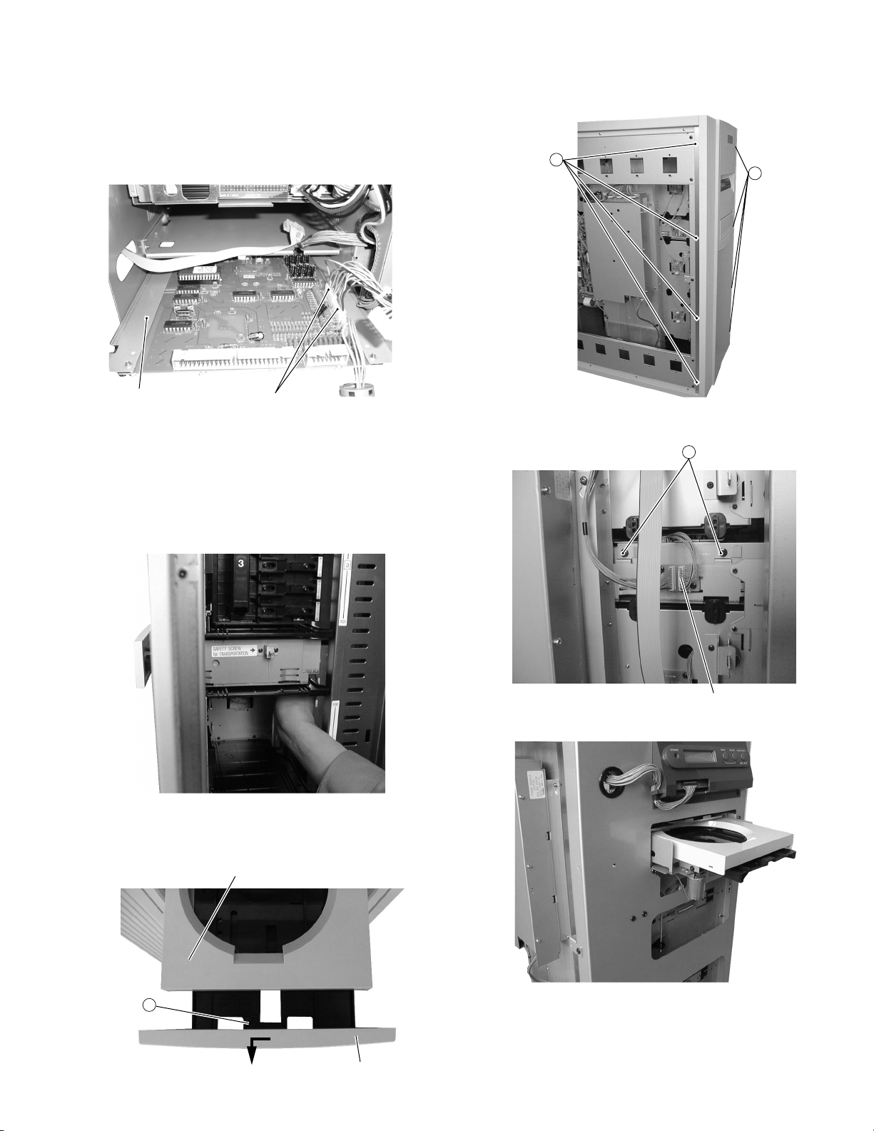
3. Remove the screw @ and pull the SCSI PCB toward you
Connector cable
15
until the connector at the right sides are exposed, then disconnect the two connectors from the chassis side.
4. Remove the SCSI PCB by pulling it toward you.
5. When mounting the SCSI PCB, insert it so that the PCB
bracket passes under the guide rails.
Connector cableBracket
2.1.13 Removing the Mail Slot
1. Open the door. (Refer to 1.1.2.)
2. Remove the side panel. (Refer to 1.1.7.)
3. Remove the #2 magazine. (Refer to 1.1.3.)
4. Insert your hand into the #2 slot and gently push the tray of
the mail slot. Pay attention not to push the tray forcibly for it
could damage the gear teeth.
6. Remove the eight screws
to remove the front panel of
$
the main unit.
14
14
7. Disconnect the connector cable on the mail CN PCB, and
remove the two screws
%
.
5. Gently pull out the mail slot tray toward you and push the
guide to the main unit side. Remove the screws
and pull
#
out the mail slot panel by sliding it toward the left.
13
Guide
Mail slot panel
8. Remove the mail slot from the front of the main unit.
2-8
Page 13
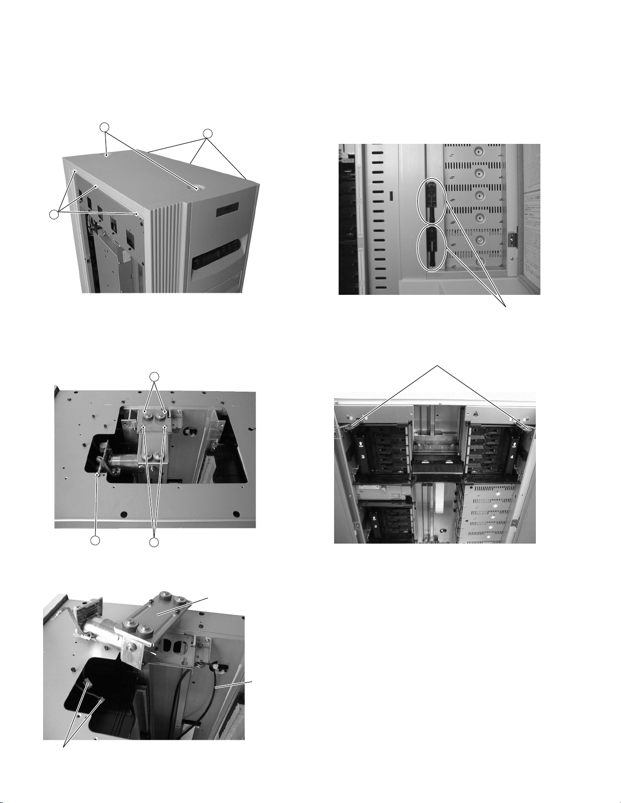
2.1.14 Removing the Top Panel
1. Open the door. (Refer to 2.1.2.)
2. Remove the side panel. (Refer to 2.1.7.)
3. Remove the two blind bolts ^ using a coin, etc.
4. Remove the six screws
16
17
to remove the top panel.
&
17
2.1.16 How to Operate with the Door Open (for Servicing)
For safety this unit is designed so as not to be operated with
the door open. When operating the unit with the door open for
maintenance or servicing, proceed in the following manner.
1. Open the door. (Refer to 2.1.2.)
2. Remove the two interlock release bars on the center panel
which turns the interlock switch to ON.
2.1.15 Removing the U/D Motor
1. Remove the top panel. (Refer to 2.1.14.)
2. Remove the screws
3. Loosen the two screws
and two screws (.
*
, and pull out the U/D motor by
)
sliding it toward the door side.
19
18
20
4. Disconnect the two connector cables from the U/D motor.
5. Remove the U/D belt to remove the U/D motor.
U/D Motor Ass'y
Release bars
3. With the door open, insert the interlock release bars into the
interlock switch holes located at both the left and right sides.
Interlock Release Bar
4. With this operation, the unit enters the mode in the same
way as with the doors closed, and you can operate the unit
as normally.
Connector cable
2-9
Belt
Page 14
2.2 Special Operation Mode
• Operating Condition
The external control equipment must not be connected to the SCSI connector. (That is the CD/DVD Library is not operated as a
part of the system.) If the special operation mode is activated in the system operating condition, the correct operation will not be
guaranteed.
• Mode Setting
As shown in the table below, the operation mode is determined depending on the status of each switch at the moment when the
CD/DVD Library's power is turned ON.
("–" in the table below is the conventional symbol for OFF. )
M: Mode S: Select L/E: Load/Eject E: Enter 0-9: Numeric keypad
SW Status
MSL/E E 01234589
————————————Normal mode —
—————ON——————Package mode 2-16
——————ON—————Disc return mode 2-16
———————ON————Memory clear mode 2-16
—————ON——ON———Auto check mode 2-16
ON —ON—————————Disc tray check mode 2-16
—ONON —————————Auto tray check ON/OFF switching 2-17
Running modes for use in factory production.
Cannot be used in servicing.
———ON———ON————
———ON———————ONManual mode 2-11
——————————ON—Drive detection mode 2-17
Other than the above, a self-check mode for use during maintenance is also available (by turning the power ON while pressing the
MODE key).
* In the Disc Return, Memory Clear, Disc Tray Check or Auto Tray Check ON/OFF Select mode, the CD-ROM Library operates in the
normal mode after the corresponding operation is completed.
* Since each operation mode other than normal mode (including Disc Return, Memory Clear, Disc Tray Check and Auto Tray Check
ON/OFF Select modes) is performed with the door open, the interlock release lever must be inserted into the interlock switch hole.
(Each of the mode will not operate correctly with the door open but without the interlock release bar because the 15V power is
turned OFF.)
* Also if the printer panel is open, the 15V power is OFF and the Library operation is not available.)
Running mode (5) (Production running)
Running mode (1) (Mechanism running)
Running mode (3) (Demonstration running)
Operation Mode
Page
2-11
2.2.1 Running Modes
1. Details of Running
* During running mode, the "RUNNING MODE" warning and the number of times appear on the LCD display. During demonstration
mode, the "DEMONSTRATION MODE" warning and the number of times appear.
* All the magazines must be installed. (However the demonstration mode automatically detects the presence of magazines, and only
the installed magazines are accessed.)
2-10
Page 15

Demonstration Mode
1
(1) Purpose
This mode is used to perform a demonstration of the CD/DVD changer operation.
(2) Start
While pressing the “ENTER” key and the numeric key “3” simultaneously, turn the power ON.
* It is not necessary to set the discs on each tray. (A disc presence check is not performed.)
(3) Operation
Repetition of crossing operation.
Disc Access (MC-8200U: when drives 1 and 2 are connected)
• Crossing Operation
Count Access Address
0001 “200” → DR1 → “200”
0002 “001” → DR2 → “001”
0003 “199” → Mail slot → “199”
0004 “002” → DR1 → “002”
0005 “198” → DR2 → “198”
0006 “003” → Mail slot → “003”
0099 “101” → DR1 → “101”
0100 “100” → DR2 → “100”
(4) Operation Stop
When the numeric key “3” is pressed during demonstration, the operation stops after the disc being accessed is returned to the
original magazine.
(5) Operation Restart
When the “ENTER” key is pressed in the demonstration-stop mode, the operation restarts from the tray next to the one being
accessed the previous time.
2.2.2 Access Counter Clearance
1.Set to display the contents shown on page 29 of the instruction manual.
2.Hold the SELECT key until the unit to be cleared appears in the 1st line.
3.With the unit counter to be cleared shown on the 1st line, hold the ENTER key for more than 5 seconds.
2.2.3 Manual Operation
MANUA L MODE
S ELECT : 00
Select SUBMODE using the numeric keys
ENTER
(00 - 07, 0 - 1; : 1 - 4)
After selecting, press ENTER key
MANUA L MODE
00
Pressing numeric key 1 - 5 activates the corresponding operation
(refer to the table on the next page).
2-11
Page 16
Carrier Manual Operation
1
· Carrier upward operation (SUBMODE = 00)
Function Numeric key
Upward normal move
Upward low-speed move
Upward 1-slit move toward left
Upward 1-slit move toward right
Upward 1-step advance
1
2
3
4
5
· Carrier downward operation (SUBMODE = 01)
Function Numeric key
Downward normal move
Downward low-speed move
Downward 1-slit move toward left
Downward 1-slit move toward right
Downward 1-step advance
1
2
3
4
5
· Tray lock/release operation (SUBMODE = 02)
Function Numeric key
Left tray lock release
Tray lock initial
Right tray lock release
1
2
3
Details
During key is ON (Condition: Tray lock initial position)
During key is ON (Condition: Tray lock initial position)
Each time key is ON (Condition: Tray lock initial position)
Each time key is ON (Condition: Tray lock initial position)
Each time key is ON (Condition: Tray lock initial position)
Details
During key ON, until lower limit sensor is reached (Condition: Tray lock initial position)
During key ON, until lower limit sensor is reached (Condition: Tray lock initial position)
Each time key is ON (Condition: Tray lock initial position)
Each time key is ON (Condition: Tray lock initial position)
Each time key is ON (Condition: Tray lock initial position)
Details
During key ON, until left tray lock is released
Each time key is ON
During key ON, until right tray lock is released
· Catcher operation (SUBMODE = 03)
Function Numeric key
Catcher leftward move
Catcher rightward move
1
2
During key is ON
During key is ON
Details
· Tray pickup/return operation (SUBMODE = 04)
Function Numeric key
Left tray auto loading
Right tray auto loading
Tray auto return
1
2
3
Each time key is ON (Condition: Tray lock initial, Catcher position right)
Each time key is ON (Condition: Tray lock initial, Catcher position left)
Each time key is ON (Condition: Tray lock initial, Catcher position left or right)
Details
* Left (Right) Tray Auto Loading Operation
1. Catcher moves toward left (right) → 2. Left (right) tray lock release → 3. Tray pickup
* Tray auto return operation
1. Catcher moves toward the direction of the tray lock pin (Tray return) → 2. Tray lock initial When the printer operation is performed,
set the disc-in tray on the printer beforehand.
· Mail slot operation (SUBMODE = 05)
Mail slot ejecting
Mail slot loading
Function Numeric key
1
2
During key is ON, until eject position is reached
During key is ON, until loading position is reached
Details
· Optional printer operation (SUBMODE = 06)
Printer ejecting
Printer loading
Function Numeric key
1
2
Each time key is ON, until ejecting position is reached
Each time key is ON, until loading position is reached
Details
2-12
Page 17
· Disc inversion operation when an inversion carrier is installed (SUBMODE = 07)
Function Numeric key Details
Arm upward movement 1 During key is ON (Condition: Tray lock initial)
Arm downward movement 2 During key is ON (Condition: Tray lock initial)
Disc inversion 3 Every time key is ON (Condition: Tray lock initial)
Drive Manual Operation
2
· Clamping & Clamping release operation (SUBMODE = □ 0) □ : Drive No. 1 - 4
Function Numeric key
Drive clamping
Drive clamping release
1
2
During key is ON, until clamping position is reached
Each time key is ON
Details
When the MC-R200U drive is used and the tray is in the drive, the clamping release operation is activated 3.5 seconds later (however,
the 1st operation for each drive starts after 7 seconds) the key is turned ON (the motor starts rotating) to wait until the disc revolution
stops.
· Play operation (SUBMODE = □ 1) □ : Drive No. 1 - 4
Play ON
Play OFF
Function Numeric key
1
2
Each time key is ON (Condition: CD-ROM disc must be clamped)
Each time key is ON (Condition: CD-ROM disc must be clamped)
Details
2.3 Self-Diagnostic Display
When a trouble occurs, this unit repeats the required process and then stops operation. In case of the trouble on a drive, the defective
drive is cut by the host PC and the operation continues with the other drives. When the trouble occurs on all drives, this unit enters the
mechanism stop operation. (The power indicator blinks when trouble occurs in all cases and the error massage is displayed on the
LCD screen.)
The trouble codes of the last eight times are stored in the memory and maintained even when the power is turned off.
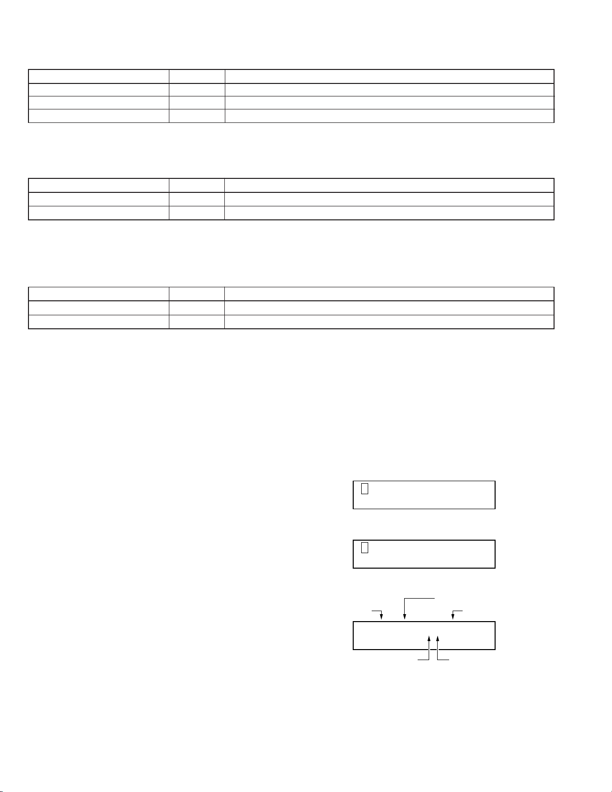
2.3.1 Displaying Trouble History
(Operate with front panel switch to display on the LCD)
How to display trouble history
Press the MODE switch to show the MENU display.
1
Press the SELECT switch to select the trouble history dis-
2
play mode.
Press the MODE switch to display the trouble history.
3
When an error occurs continuously in a single trouble history, the detailed information is displayed in the second row.
Each time the SELECT switch is pressed, the trouble history
4
is changed in sequence.
MENU display
Trouble No.
Troubled Unit
C: Carrier
M: Mail Slot
D1 - D6 : Drive
NORMAL DISPLAY
1.
2.
ERROR DISPLAY
ERROR DISPLAY
2.
ID NO. DISPLAY3.
Disc No.
ER1 : 107–CU08
–CC20
Unit Detailed Code
Trouble Code
2-13
Page 18
2.3.2 Display When Trouble Occurs
In case of an error, the front panel indicator blinks and the LCD shows the error details by overriding any other information.
The indicator blinks.
LCD displays in case of error
ERROR OCCURRED !
If the transport lock of the carrier has not been unlocked,
this section shows “CHECK CAR. SCREW”.
DISC = 024
CODE = CU–04
E RORMAGAZINE
R
No. : –2
POWER
Display when
CODE = CC-31
MODE SELECT
1 2 3 4 5 6 7 8 9 0 E
LOAD/EJECT
MAIL SLOT
DISC = 024
Disc No.
CODE = CU – 04
Error code
Unit detail code
Unit in error
Disc No. : Shows the disc No. being accessed at the moment of error
occurrence. "---" is displayed if no disc is accessed at the moment
of error occurrence.
Units in error and unit detail codes
Unit in error Unit detail code
C
M
D1 to D4
P Color Disc Printer
Carrier
Mail slot
Drive
U
L
C
D
Up/down
Tray lock
Catcher
Disc
F Flip
E
L
T
T
C
E
D
S
Ejection
Loading
Tray
Tray
Clamp
Ejection
Disc
Spindle
T Tray
2-14
Page 19
2.3.3 Erasing the Trouble History
The error history can be cleared by pressing ENTER key for more then 5 seconds during displayed error history.
2.3.4 Error code list
Device
Device
part
Error
code
01 UP/DOWN rotary sensor does not change
02 Left slit sensor does not change
03 Right slit sensor does not change
CU 04 UP/DOWN motor does not function
07 UP/DOWN motor drive short-circuits and over-current is detected
08 UP/DOWN operation exceeds the predetermined duration
09 Lower limit sensor turn on during UP/DOWN operation
10 Tray lock release not possible
CL 11 Tray lock impossible, or lane change not possible
12 Tray lock does not exist at the initial position during carrier movement
20 Catcher (right → left) movement operation exceeds the predetermined duration
21 Catcher (left → right) movement operation exceeds the predetermined duration
22 Catcher (right → left) convergence operation exceeds the predetermined duration
23 Catcher (left → right) convergence operation exceeds the predetermined duration
24 Catcher (right → left) tray rotary sensor does not change
25 Catcher (left → right) tray rotary sensor does not change
CC 26 Right catcher sensor does not turn on
27 Left catcher sensor does not turn on
28 Catcher motor (right → left) does not function
29 Catcher motor (left → right) does not function
30 Tray does not exist
2
31*
Magazine insertion incomplete, or sensor defective
32 Over-current is detected during catcher motor operation
CD
41 Destination-unknown tray exists on the carrier
42 No disc in the tray
43 Flip tray does not exist
F
80 During the flip raise operation, the expected time required is over
81 During the flip descent operation, the expected time required is over
E50Mail Slot ejecting is not possible
ML 51 Mail Slot loading is not possible
T52Destination-unknown tray exists in the Mail Slot
60 Destination-unknown tray exists in the Drive and the control cable of the Drive is disconnected.
61 Tray removal is not possible at the drive position
(D#)*
1
T
C62Disc clamp of the drive does not function
E63Drive ejection is not possible
D64Failure to remove the disc from the drive
S65Spindle motor fails to stop
PT72 Destination-unknown tray exists in the Label Printer
*1: # represents the drive number.
*2: Check the magazine loading condition.
Description
2-15
Page 20
2.4 Auto Check Mode
2.6 Tray Auto Return Mode
(1) Purpose:
Simply checks the tray transfer operation for all units.
(2) Control:
Set the release bars, then turn the power to ON while pressing the key “1” and “4”on the 10-key Pad.
Check that there is no tray in the drive or mail slot. If this is
not sure, first perform the tray auto return mode operation
described in 2.6.
(3) Operation:
Accesses to the 2nd address (Tray No. 49 in the magazine)
from the top and the 2nd address (Tray No. 02 in the magazine) positions, drive and mail slot positions.
Operation Sequence
(MC-8200LU : when drive 1and 2 are connected)
Address 199 → Drive 1 → Address 199
1
Address 152 → Drive 2 → Address 152
2
Address 149 → Mail Slot → Address 149
3
Address 102 → Address 102
4
Address 99 → Address 99
5
Address 52 → Address 52
6
Address 49 → Address 49
7
Address 2 → Address 2
8
(4) Display during auto check mode
R UNN I NG MODE
4–099
Tray No. being accessed.
However, “END” appears when finished.
(1) Purpose:
If the tray is left in the drive or the mail slot, performs the
operation to return the tray to the original magazine.
(2) Control:
Set the release bars, then turn the power to ON while pressing the key “2”on the 10-key Pad.
(3) Operation:
Performs carrier initial operation.
1
Check whether the tray is left in the drive 1 or not. If the
2
tray is left in, it is returned to the memorized magazine.
The same operation as (2) is performed for drives 2 to 6
3
respectively.
Checks whether the tray is left in the mail slot or not. If
4
the tray is left in, it is returned to the memorized magazine.
Operation completed.
5
2.7 Disc/Tray Check Mode
(1) Purpose:
Checks the presence/absence of the tray/disc in the magazine and stores the information in the CPU as the mapping
data.
(2) Control:
While pressing the MODE switch and LOAD/EJECT switch
simultaneously, turn the power ON.
(3) Operation:
Performs carrier initial operation.
1
Takes up the tray in the address “001” on the carrier and
2
checks the tray and disc, then returns it to the original
position.
Performs the operation described in (2) for addresses till
3
“200” (address “600” for MC-8600LU).
Operation completed.
4
2.5 Packaging Mode
(1) Purpose:
For shipping the library’s main unit, the carrier mechanism is
moved to the fixing position located at the lower end of the
unit and the drive is clamped.
(2) Activation:
Set the release bars, then turn the power to ON while pressing the key “1” on the 10-key Pad.
(3) Operation: (when Drives 1 and 2 are connected)
Performs carrier initial operation.
1
Checks whether the tray is left in the mail slot or not. If
2
the tray is left, it is returned to the magazine.
Checks whether the tray is left in the drive 1 or not. If the
3
tray is left, it is returned to the magazine.
Checks whether the tray is left in the drive 2 or not. If the
4
tray is left, it is returned to the magazine. (The same
operation is performed when drives 3 to 6 are installed.)
Moves the carrier mechanism to the shipping position.
5
Performs clamping operation for the drive 1.
6
Performs clamping operation for the drive 2. (The same
7
operation is performed when the drive 3 to 6 are installed.)
2.8 Memory Clear Mode
(1) Purpose:
Clears the backup memory for the mechanism CPU and SCSI
CPU, including to reset the disc/tray mapping data and SCSI
ID of the main unit, etc.
(2) Control:
While pressing the key “3”on the 10-key Pad., turn the power
ON.
(3) Operation:
Performs the tray auto return mode operation.
1
Clears the backup memory for the mechanism CPU and
2
SCSI CPU.
* Be sure not to turn the power OFF until the mechanism
operation is completed because the memory is cleared
after the trays left in the drive/mail slot are returned.
Operation completed.
3
2-16
Page 21
2.9 Drive Detection Mode
(1)Purpose
Drives are detected in order to prevent simultaneous installation of different drives.
(2)Start
While pressing the “8” key, turn the power ON.
(3)Operation
After the initial operation, each of the installed drives performs the ejection operation for identification.
LCD display during drive detection LCD display after drive detection
DETECTING DRIVES
. . . . PLEASE WAIT
Note: Whenever a drive is added, replaced or removed after the last drive
detection, be sure to repeat drive detection.
* If this is omitted, a mechanism malfunction may result.
* Be sure to turn the power OFF and then ON again after drive detection.
DRIVE DETECTION
COMPLETED
2-17
Page 22
2.10 Maintenance Mode
1234
6
7
89
5
2.10.1 Outline
This unit is also equipped with an RS-232C port as an interface
for external equipment other than the SCSI interface which is
used for connection to the host computer. The RS-232C port is
used mainly for the following two purposes:
(a) Remote Maintenance:
It can be used for remote diagnostic operation by connecting
to the public telephone line via a modem.
(b) Direct Maintenance:
It can be used for diagnostic operation by direct connection
to a computer, etc.
In either way, while this unit is operated in the system the mechanical operation checking, which is one of the checking functions of the self-diagnosis operation, is not available.
(a) Remote maintenance
RS-232C
Modem
Library
SCSI
HOST
(b) Direct maintenance
●Maintenance by
Library
the same host
RS-232C
HOST
SCSI
*Judgment whether remote or direct maintenance Checks
whether the modem is connected or not when the power is
turned ON, and judges the unit is in the “remote maintenance”
or “direct maintenance” mode.
· The modem control AT command (Z: Reset) is transmitted to
the RS-232C port. And if there is a response, the unit is operated as the “remote maintenance” mode, and if there is no
response, the unit is operated as the “direct maintenance”
mode.
NOTES:
In the “direct maintenance” mode, the host computer must
not respond to an AT command.
Public Tel line
Modem
PC
●Maintenance using
Library
exclusive PC
RS-232C
SCSI
HOST
PC
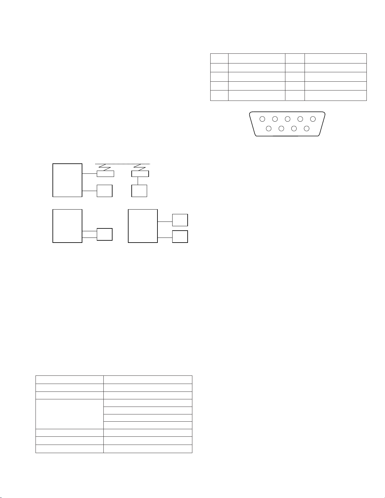
• Connector: D-Sub 9-pin (male)
• Pin Layout
1
2
3
4
5
DCD (IN)
RXD (IN)
TXD (OUT)
DTR (OUT)
S-GND
6
7
8
9
DSR
RTS (OUT)
CTS (IN)
NC
2.10.3 Maintenance Types and Conditions
Operating environment status
1
Outputs the environmental conditions including the type of
this unit (Model No.), status of connected drives, SCSI ID
No. setting and ROM version, etc.
Trouble contents check
2
Outputs the trouble information stored in this unit.
Self diagnostic function
3
Performs the preset specific operations and outputs the results as the status. Operations 1 and 2 are available at any
time. The operation
is available only when this unit is in
3
the maintenance mode. Regardless of the currently selected
maintenance mode (remote or direct), all the peripheral components must be turned on before turning on the power to
this unit.
2.10.4 Activating the Maintenance Mode
To activate the maintenance mode with this unit...
Set the maintenance disc in the address 1 before turning the
1
power ON.
While pressing the MODE switch on the front panel, turn the
2
power switch to ON.
2.10.5 Maintenance Program
To perform maintenance on this unit, the maintenance program
software must be installed on the PC connected.
2.10.2 Electrical Specifications
• Signal Format
Signal Level RS232C
Communication System Asynchronous half-duplex
Transfer Rate 9600 bps
Character Start bit: 1
Codes used ASCII character code
Modem Control Command Compliant to Hayes AT command
Compatible Modem ITU-T V.32
Data: 8 bits
Parity: None
Stop bit: 1
2-18
Page 23

2.11 Auto Disc/Tray Check ON/OFF Setting
On shipping, auto disc/tray checking function is set to ON which automatically checks the discs loaded in the magazine after the
magazine is loaded or unloaded with the power ON. This setting can be switched OFF in the following manner.
1. Changing the setting
While pressing the SELECT switch and the LOAD/EJECT switch located at the side of the LCD, turn the power ON. The operation
mode is alternated between ON and OFF. The default setting is ON (auto check function is activated). With the above operation,
the setting is changed to OFF (auto check function is deactivated).
2. How to check the current setting
· Hold down the MODE switch beside the LCD for more than 5 seconds. The current setting is displayed on the LCD.
AUTO DISC CHECK :
ON
AUTO DISC CHECK :
OFF
3. Others
· This setting is maintained after the power is turned off. Changing the setting requires the operation described in 1.
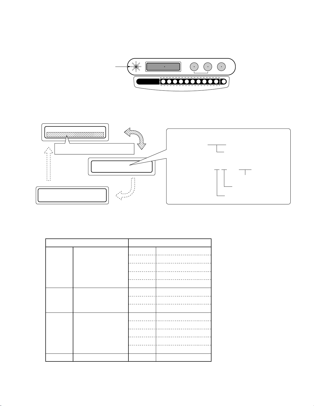
2.12 Maintenance and Periodical Check
The following shows an example of a maintenance reference chart when this unit is used with two drives for 50,000 times a year.
Maintenance period differs depending on the using conditions, etc.
Item Maintenance Contents
Carrier
U/D Motor Unit
Mail slot
Drives
Air filter unit
Magazine
: Replacement. ^ : Maintenance. : Operation check.
1yr 2yrs 3yrs 4yrs 5yrs 6yrs
^
–––––
––^ ––
––^ –– ^
Operation check contents
Item Check Contents
Carrier
U/D motor assembly
Mail slot
Drives
Magazines
Presence/absence of abnormal sound or backlash, Roller defect/wear, No defect on carrier FCC cable
Presence/absence of abnormal sound or backlash
Presence/absence of abnormal sound or backlash
Readout speed check using exclusive software
Cleaning of tray in the position where frequently used (wipe off dust)
Maintenance Intervals
Grease (See Disassembly view.)
Clean filter
Clean tray
NOTES:
1) The maintenance and replacement intervals for the CD/DVD library are variable depending on the operating conditions such as the
number of additional optional drives and the frequency of use. It is recommended to replace each drive after every 30,000 disc
loading cycles. To check the operation of the CD/DVD drive, perform recording and playback of the exclusively designed CD/DVD
disc.
2) The service life of the CD/DVD drive is variable depending on the write count (the total time spent in the write mode).
3) Each disc carrier tray should be replaced after every operation count of 10,000 cycles.
An operation refers to each operation cycle of the carrier. When the carrier has pulled out a magazine tray, inserted a disc in it and
then returned it to its original magazine, the operation count becomes 2.
4) When an MC-CF10 optional carrier is used, it is recommended that it should be replaced after 300,000 inversion operations.
The inversion count can be checked as describe in section “11. Access Count” of the instruction manual.
2-19
Page 24

R
VICTOR COMPANY OF JAPAN, LIMITED
R
is a registered Trademark owned by VICTOR COMPANY OF JAPAN, LTD.
R
is a registered Trademark in Japan, the U.S.A., the U.K. and many other countries.
Printed in Japan
Page 25

SECTION 4
S34
CARRIER MECHA
ASSEMBLY
29
30
31
28
128
33
34
33
26
13
14
23
58
8600 only
8600
only
12
14
13
15
16
17
1
147
148
125
126
146
22
19
27
21
22
25
20
3a
2
126
127
126
29
38
33
29
33
39
64
S5
S7
S2
S2
S2
S15
S2
S1
S2
S4
S6
S8
18
120
119
122
7
8
149
150
166
6
4
7
3b
18
11
10
9
4
S1
S3
S3
S4
S4
2
S2
W3
52
52
53
54
87
55
S12
S7
S11
S12
S11
S7
33
29
35
36
37
129
29
130
33
33
32
41
42
44
83
82
85
140
86
88
79
78
91
84
30
21
27
45
21
21
51
43
29
33
29
38
S9
S11
S10
S12
S10
S13
S13
S4
S34
S26
S27 S2
S20
DISPLAY
PCB ASSEMBLY
S32
48
A
49
50
66
138
65
47
46
131
72
64
62
133
63
67
55
79
78
80
55
61
59
60
134
167
156
S11
S12
S11
S13
S12
S4
S19
S2
S2
S19
S13
S20
W1
W2
MAIL CN
PCB ASSEMBLY
MAIL SLOT
ASSEMBLY
MAGAZINE HOUSE
ASSEMBLY
CENTER PANEL (B)
ASSEMBLY
52
52
113
68
136
102
135
138
24
69
S12
S7
S2
S21
S2
S21
S11
S7
S11
103
S11
CHASSIS
PCB ASSEMBLY
POWER
UNIT ASSEMBLY
CONNECTOR
PCB ASSEMBLY
100
142
71
55
A
89
55
71
124
91
40
92
93
94
145
143
145
90
74
75
106
73
132
101
S2
S2
S4
S12
S35
S28
S2
S2
S2
S4
S4
S3
S22
S3
97
95
98
99
98
95
96
161
168
95
96
141
95
S2
S2
S2
S2
S31
123
152
151
155
173
S2
S11
MAGAZINE HOUSE
ASSEMBLY
FAN
FAN CN
PCB ASSEMBLY
55
S12
U/D MECHA
PCB ASSEMBLY
S4
S7
137
11
11
155
156A
156B
S16
S16
S7
S21
S29
144
158
159
S35
108
164
70
110
S4
S2
S30
RS232C
PCB ASSEMBLY
165
111
167
167
153
S33
SCSI PCB
ASSEMBLY
56
57
S29
163
S17
105
5
8600
only
S4
163
104
S25
81
Apply grease
on the inside.
118
S2
121
154
117
118
175
176
116
S37
115
173
S2
174
S36
114
4.1 FINAL ASSEMBLY
M1
EXPLODED VIEW AND PARTS LIST
4-1
4-1
Page 26

4.2 FINAL ASSEMBLY LIST
Symbol
No.
1 SS22761-00C DOOR PANEL (L6) MC-8600
1 SS22759-00C DOOR PANEL (L2) MC-8200
2 SS411847-00A HINGE MC-8200: x 4
03a SS412126-F0A DOOR STAY (L)
03b SS412126-R0A DOOR STAY (R)
4 SS411853-D07 SPONGE TAPE
5 SSV3871 FFC MC-8200
5 SSV3872 FFC MC-8600
6 SS411853-D10 SPONGE TAPE MC-8600
6 SS411853-D09 SPONGE TAPE MC-8200
7 SS411853-D08 SPONGE TAPE
8 SS22916-00C DOOR PANEL (R6) MC-8600
8 SS22915-00C DOOR PANEL (R2) MC-8200
9 SS22765-002 D-LOCK BASE (6) MC-8600
9 SS22764-002 D-LOCK BASE (2) MC-8200
10 SS35376-001 D-LOCK BAR (6) MC-8600
10 SS35377-001 D-LOCK BAR (2) MC-8200
11 SS35732-00A D-LOCK HOOK
12 SS22744 FRONT PANEL (M)
13 SS411853-F07 SPONGE TAPE
14 SS411853-F08 SPONGE TAPE
15 SS411931 FP-BKT
16 SS411842-010 PLATE
! 17 SS11621-003 MAIN PANEL
18 SS411853-D11 SPONGE TAPE MC-8200
18 SS411853-D12 SPONGE TAPE MC-8600
19 SS35727-001 MP ANGLE (R6) MC-8600
19 SS35725-001 MP ANGLE (R2) MC-8200
20 SS35726-001 MP ANGLE (L2) MC-8200
20 SS35728-001 MP ANGLE (L6) MC-8600
21 SS411853-F06 SPONGE TAPE MC-8200: x 2
22 SS411853-F02 SPONGE TAPE
! 23 SS11622-001 SUB PANEL MC-8600
24 SS35994-00A C-PANEL (RRB)
25 SS35729-001 SP ANGLE (R6) MC-8600
26 SS35730-001 SP ANGLE (L6) MC-8600
27 SS411853-F01 SPONGE TAPE MC-8600
28 SM3921-001 BLANK LABEL
29 SS410270 R.SHAFT
30 SS410277 R.B.SHAFT
31 SS411900-0L1 SR.BRACKET
32 SS411900-0R1 SR.BRACKET
33 SS410268-00A ROLLER
34 SS35352-00B C.BASE ASSY
35 SS410274 SP.SCREW
36 SS411895-00A R.HOLDER ASSY
37 SS411884-001 SPRING
38 SS410275-002 SPRING
39 SS411899 BELT BRACKET
40 SS412031-001 BLIND BOLT
41 SS22476-002 FILTER CASE A
42 SS34931-00A AIR FILTER
43 SS22477-002 FILTER CASE B
44 QAR0068-001 FAN MOTOR
45 SS35408 U/D BASE
46 SS411883 SP BRACKET
47 SS411884-003 SPRING
48 SS11629 MAIL BASE
49 SS411923-002 SPRING
50 SS411959-002 MTB SHAFT
M1
M1MM````
DescriptionPart No. Part Name
4-2
Page 27

Symbol
No.
51 SS411961 BRACKET
52 SS22737 SQ PLATE MC-8200: x 7
53 SS22917-00B DRIVE HOUSE ASSY
54
55 SS411880-003 WIRE CLAMP
56 SS412434-001 S-PCB BKT(B)
57 SS412433-001 S-PCB BKT(A)
58 SS413399 SWITCH SHEET
59 SS48947-002 SHAFT PIN
60 SS411886 PULLY(B) BKT
61 SS411882 PULLEY(B)HOLDER
62 SS411884-002 SPRING
63 SSV3334 PULLEY(B) ASSY
64 SSV3221 BELT MC-8200
64 SSV3220 BELT MC-8600
65 SS412134 STOPPER
66 SS413387 C-PCB BKT
67 SS22907-002 C-PANEL(RR2) MC-8200
67 SS22909-002 C-PANEL(RR6) MC-8600
68 SS22903-003 CENTER PANEL(2) MC-8200
68 SS22904-002 CENTER PANEL(6) MC-8600
69 SS22905-002 C-PANEL(BR)
70 SS35734-001 AC BARRIER
71 SS413570 C. B BLOCK
72 SS11827 GUIDE RAIL(86) MC-8600
72 SS23202 GUIDE RAIL(82) MC-8200
73 SS35349-001 CAR-TP HOOK
74 SS411085-001 SPRING(RH)
75 SS48507-002 WASHER
78 SS412015-001 SENSOR BKT
79 GP1A61LC SENSOR
80 SS412006-001 P-SW BKT
! 81 QSW0520-001 POWER SWITCH
82 SS412002-001 FCF BKT
83 HGT19-188UL-NT TAPE
84 SS35086-001 C&C FASTENER
85 SSV2622-30144B FFC CABLE MC-8600
85 SSV2622-3084B FFC CABLE MC-8200
! 86 SS11623-00D CONT.PANEL ASSY
87 SS413012 F.BKT
88 RCM2060M-B L.C.DISPLAY
89 SS411880-006 WIRE CLAMP
90 SS11638-002 C-PANEL(T)
91
92 SS412005-001 P.CN-PCB BKT
! 93 QAL0538-001 POWER SUPPLY
94 SS35437-001 C-PCB HOOK
95 SS412012-S03 CUSHION MC-8200: x 2
96 SS412012-S02 CUSHION MC-8600
97 SS22793-002 SIDE PANEL(T6) MC-8600
98 SS412012-S01 CUSHION
99 SS22792-002 SIDE PANEL
100 SS22908-002 C-PANEL(RL2) MC-8200
100 SS22910-002 C-PANEL(RL6) MC-8600
101 SS411149-005 PCB HOLDER
102 SS413617-001 C. LABEL-001
103 QNZ0676-001 CONN ACCESSORY
104 SS412017-012 EDGING
105 SS413010-002 FINGER
106 SS22906-002 C-PANEL(BL)
DescriptionPart No. Part Name
MC-12-UD-PULLY (No. 59 and No. 63) will be sup-
plied as it can not be disassembled.
4-3
Page 28

Symbol
No.
107 SS412013-001 AC PANEL
! 108 QNC0048-001 AC INLET
109 SS412001-001 D-SUB PANEL
110 SS411956 STUD
111 SSV2459-09 DUSTER COVER
112 SS35436-001 DH-COVER
113 WJS0037-001A E-FL/RE WIRE
114 SS412019-002 BLIND PANEL
115 SS36280 REAR PANEL (DH)
116 SSV2458-050 D-SUB CAP
117 SS412012-R07 CUSHION
118 SS412012-R08 CUSHION
119 QAR0261-001 FAN MOTOR
120 SS36338 FAN BKT
121 SS35720-002 REAR PANEL(B)
122 SSV3695 FAN GUARD
123 SS36284 REAR PANEL(T2) MC-8200
123 SS23206 REAR PANEL(T6) MC-8600
124 SS35478-00G CABI ASSY(8600)+D.HOUSE MC-8600
124 SS35477-00G CABI ASSY(8200)+D.HOUSE MC-8200
125 SS412123-001 C.LABEL
126 SS32387-00D LOCK KEY ASSY
127 SS411843-001 D LOCK CAM
128 MC22-CARR CARRIER MECHA ASSY
129 SS412157 EARTH
130 SS412138-002 CUSHION
131 MC12-UD-M U/D MOTOR ASSY
132 SS412017-012 EDGING
133 MC12-MAIL MAIL SLOT ASSY
134 SS412138-001 CUSHION
135 SS412139-001 IL RELEASE BAR
136 SS412038-001 No. LABEL(1 50)
136 SS412038-002 No. LABEL(51 100)
136 SS412038-003 No. LABEL(101 150)
136 SS412038-004 No. LABEL(151 200)
136 SS412038-005 No. LABEL(201 250) MC-8600
136 SS412038-006 No. LABEL(251 300) MC-8600
136 SS412038-007 No. LABEL(300 350) MC-8600
136 SS412038-008 No. LABEL(351 400) MC-8600
136 SS412038-009 No. LABEL(401 450) MC-8600
136 SS412038-010 No. LABEL(451 500) MC-8600
136 SS412038-011 No. LABEL(501 550) MC-8600
136 SS412038-012 No. LABEL(551 600) MC-8600
137 SS412043-001 CAUTION LABEL
138 SS412352-001 CAUTION LABEL
140 SSV2923 FLAT CORE
141 MC82-CHAS CHASSIS PCB ASS’Y
142 SS411880-004 WIRE CLAMP
143 SS412125-001 IL RULER
144 SS412125-002 IL RULER
145 QSW0540-001 SW
146 SS412039-001 KEY LABEL
147 SS35506-002 C. LABEL(TPS/JP)
148 SS35448-002 C. LABEL(TRY/JP)
151 SS412562-001 RATING LABEL
152 SS412084-002 FCC LABEL
153 SS48287-002 CAUTION. LABEL
154 SC40865-001 WARNING. LABEL
155 SS412043-001 CAUTION. LABEL
156A SS412047-001 UL LABEL
DescriptionPart No. Part Name
Symbol
No.
156B SS412174-002 CE/TUV LABEL
157 SSV2923 FLAT CORE
158 QSW0540-001 MICRO SWITCH
159 SS412476-001 CPL SW BASE
161 SS47383-001 C. LABEL
163 QQR0216-001 CLAMP FILTER CN13(for AP), CN900 (for CHAS),
164 SS412732-A0040 GASKET
165 SS412017-012 EDGING
166 SS412732-B0030 GASKET
167 SS412012-C01 CUSHION
168 SS412716-001 C. LABEL
169 SS413622-001 C. LABEL
171 SS413601 S. PCB BRACKET
173 SS413386 REAR PANEL HOOK
174 LS40403-001A CON. PLATE
175 LS30371-001A PWB BASE
176 SK250400A1 LVD PWB ASSY
S1 SS411848-001 SCREW
S2 QYSDSTY3006X SCREW
S3 SS411339-001 SCREW
S4 QYSDST3006M SCREW M3 x 6
S5 QYSDSP3006M SCREW M3 x 6
S6 QYSBSFG3006M SCREW
S7 QYSBSF3008M SCREW M3 x 8
S8 QYSDSF3006M SCREW
S9 QYSBSF3012M SCREW
S10 QYSBSF4035M SCREW
S11 QYSDST4008M SCREW M4 x 8
S12 QYSPSPD4008Z SCREW M4 x 8
S13 QYSPSPD3006Z SCREW
S14 QYSBST4008N SCREW M4 x 8
S15 QYSDSP3005M SCREW
S16 QYSPSP2604Z SCREW
S17 SS411759-002 SCREW
S18 QYSDST3006Z SCREW M3 x 6
S19 QYSDSP4008M SCREW
S20 QYSDST3010M SCREW M3 x 10
S21 SXST4008N SCREW
S22 QYSPSPD4010Z SCREW M4 x 10
S23 QYSDSTY3006N SCREW
S24 QYSBSTG3010M SCREW
S25 QYSDST3008M SCREW M3 x 8
S26 QYSBSFG3008M SCREW
S27 QYSDSP2004N SCREW M2 x 4
S28 QYAPSPL4010Z SCREW M4 x 10
S29 QYSBST3006X SCREW M3 x 6
S30 QYSSST3008M SCREW
S31 QYSPSP3008Z SCREW M3 x 8
S33 QYSDSTY3008X SCREW
S34 QYSBSTG3008M SCREW
S35 QYSPSPL2310Z SCREW
S36 LS40316-001A SCREW x 2
S37 QYSDST3006N SCREW M3 x 4
W1 QYWSS439008Z WASHER
W2 QYREE2500 E WASHER
W3 QYWFM31540 WASHER x 2 MC-8600
DescriptionPart No. Part Name
4-4
4-4
Page 29

15
16
17
18
25
24
26
23
17
20
31
89
90
30
29
33
39
87 88
35
36
32
38
69
70
73
74
75
76
77
78
81
82
68
67
65
64
63
62
66
84
61
59
60
48
47
45
43
42
40
41
44
41
40
51
50
52
45
55
58
57
56
53
54
49
83
5
6
3
2
42
46
85
79
80
72
71
34
27
28
22
19
21
14
13
12
11
8
86
9
10
7
12
4
S1
D.SEN T.PCB ASSEMBLY
DISC SEN R
PCB ASSEMBLY
L CATCH SEN
PCB ASSEMBLY
TRAY LOCK S
PCB ASSEMBLY
L ADD SEN PCB ASSEMBLY
R ADD SEN PCB ASSEMBLY
LOADING SEN PCB ASSEMBRY
LANE SEN PCB ASSEMBRY
CARRIER MEC PCB ASSEMBRY
R CATCH SEN
PCB ASSEMBRY
S1
S1
S1 S6
W3
W3
W1
S6
S7
S4
S1
S4
S1
S1
S1
S1
S10
W4
W5
S8
S8
S9
W5
S9
S11
S10
S9
S1
W1
S1
S1
S5
S1
S1
S3
S2
S1
S1
S1
W1
W6
S3
W1
S1
W2
W1
S4
W4
W4
S2
S13
S1
S12
W4
W7
Apply grease
on the back
side all over.
33 65
Motor pin
* and is solder to case.
4.3 CARRIER ASSEMBLY
Apply grease (G-31KAV)
M2
4-5
4-5
Page 30

4.4 CARRIER MECHANISM ASSEMBLY LIST
Symbol
No.
2 SS35406-002 ILL.BRACKET
3 SS412167 TL-BRACKET
4 SS35343-001 T.L HOLDER
5 SS411943 T-LINK
6 SS35343-002 T.L HOLDER
7 SS22745-00B C.CHASSIS ASSEMBLY
8 SS22739 TRAY GUIDE(F)
9 SS48906-003 STOPPER(1)
10 SS411807-002 PUSHER
11 SS411807-001 PUSHER
12 SS411908-001 SPRING
13 SS22740 DISK STOPPER(F)
14 PHY214PH02N WIRE ASSEMBLY
15 SS411912 H.RAIL
16 SS410979-004 S.SUPPORT
17 SS410982-002 C.H.S.BEARING
18 SS412600-002 C.SLIDER
19 SS412600-001 C.SLIDER
20 SS410978-00C S.SUPPORT ASSEMBLY
21 SS48874 J.GEAR
22 SS411806 J.GEAR
23 SS410295 C.H.S.GEAR
24 SS411904 C.H.W.GEAR
25 SS34908-00D C. HOLDER ASSEMBLY
26 SS411903 H.SHAFT
27 EHT309EH03N WIRE
28 EHT312EH03N WIRE
29 SS35405 T.G.HOLDER
30 SS22741 T.GUIDE(R)
31 SS35344-002 DISK STOPPER(R)
32 SS410976 S.BASE
33 SSV2793 DC MOTOR
34 SS411906-00A TLM BRA ASSEMBLY
35 SS48863-002 SL.GEAR
36 SS412601-00B SENSOR GEAR ASS’Y
38 PHY412PH04N WIRE
39 SM3921-001 LABEL
40 SS410973 LSP.SHAFT
41 SS410972-002 L.SPRING
42 SS410966 C.S.SHAFT
43 SS411915-00A LEVER(R) ASSEMBLY
44 SS411902-00A LEVER(L) ASSEMBLY
45 PHY307PH03N WIRE
46 SS411003-001 CS.BRACKET
47 SS411002-002 SPRING
48 SS411907-00B T.STOPPER ASSEMBLY
49 SS411003-002 CS.BRACKET
50 SS411002-001 SPRING
51 SS411907-00A T.STOPPER ASSEMBLY
52 EHT212EH02N WIRE
53 PHYD06PH05N WIRE ASSEMBLY
54 SS410991-00A TL.BRACKET ASSEMBLY
55 SS410993-00A T.L-LINK ASSEMBLY
56 SS411911 TLS.BRACKET
57 SS410997-002 SPRING
58 SS410996 TL SCREW
59 SS410999 SCREW
60 SS411918-00A CAM BRACKET
61 SS411008-002 BRACKET
62 SS411009-002 MOTOR BRACKET
M2
M2MM````
DescriptionPart No. Part Name
MC12-LOAD-M (LOADING M ASSY) will be sup-
plied as it can not be disassembled.(W4 and S10
is included)
Symbol
No.
63 SS411007 W.SHAFT
64 SS411006 WORM GEAR
65 SSV2793 DC MOTOR
66 SS411004-00A BASE ASSEMBLY
67 SS411025 R.PLATE
68 SS411010 GUIDE
69 SS411026-00A PLATE ASSEMBLY
70 SS411022-00A BRACKET ASSEMBLY
71 SS411011-00A WORM WHEEL ASSEMBLY
72 SS411017-003 PL BASE
73 SS411016 SLIDER
74 SS410961-002 SPRING
75 SS411015 S.BRACKET
76 SS411018-00A L.BRACKET ASSEMBLY
77 SS411021 PIN
78 EHT308EH03N WIRE
79 SS411044-002 CUSHION
80 SS411044-001 CUSHION
81 SS411035 WC BRACKET
82 SS411394-00B C.WIRE ASSEMBLY
83 SS411394-00A C.WIRE ASSEMBLY
84 SS411340 BUSH
85 SSV2622-3084B FLAT CABLE MC-8200
85 SSV2622-30144B FLAT CABLE MC-8600
86 QCFB1HZ-104YR C CAP
87 SS411415 S.BRACKET
88 SS411419-001 SPRING
89 SS412141-001 PROTECTOR
90 SS412141-002 PROTECTOR
S1 QYSDSF3008M SCREW M3 X 8
S2 QYSDSP2604M SCREW M2.6 X 4
S3 QYSBSFG3008M SCREW M3 X 8
S4 QYSDSP2004M SCREW M2 X 4
S5 QYSDSP2008M SCREW M2 X 8
S6 QYSDST2005Z SCREW M2 X 5
S7 QYSBSF2606Z SCREW M2.6 X 6
S8 QYSDSP2006M SCREW M2 X 6
S9 QYSDST3006M SCREW M3 X 6
S10 QYSPSP3003Z SCREW M3 X 3
S11 QYSPSPD3006M SCREW M3 X 6
S12 QYSDSF2004M SCREW M2 X 4
S13 QYSDSP3006M SCREW M3 X 6
S14 QYSDST3008M SCREW M3 X 8
W1 QYREE2000X E RING
W2 QYWSS327005Z WASHER
W3 QYWFM264750 POLY WASHER
W4 QYREE1500 E RING
W5 QYREE3000X E WASHER
W6 QYWFM315450 POLY WASHER
W7 QYWFM315425 WASHER
DescriptionPart No. Part Name
MC12-TR-M (TRAY LOCK M ASSY) will be sup-
plied as it can not be disassembled.
4-6
4-6
Page 31

4.5 MAIL SLOT ASSEMBLY
13
15
11
14
16
9
10
8
12
W1
W2
S3
S3
S1
S1
W1
W4
3
4
2
1
5
6
7
S1
S2
S1
S1
S1
S2
POSI PCB ASSEMBLY
SENSOR PCB ASSEMBLY
CN6
28
31
32
30
29
27
25
26
24
23
22
35
33
37
36
34
W2
W3
S2
S3
S6
S5
S4
S3
S7
39
From MOTOR
From SENSOR BOARD
From POSI BOARD
From SW
MAILSLOT PCB ASSEMBLY
19
17
18
20
21
S3
S3
S1
S3
S3
S1
S4
Motor pin
Apply grease (G-31KAV)
M3
4-7
4-7
Page 32

4.6 MAIL SLOT ASSEMBLY LIST
Symbol
No.
1 SS11616-002 GUIDE
2 SS411934 TGR BRACKET
3 SS35350 TRAY GUIDE(R)
4 SS22743-002 BASE
5 SS35349 T.RAIL(F)
6 SS411927-00B TGF BKT ASSEMBLY
7 SS411923-001 SPRING
8 SS35348 TL PUSHER
9 SS411938 TLG BRACKET
10 SS411920 TRAY LOCK
11 SS411919 SL SHAFT
12 SS411924-002 ST BRACKET
13 SS411925-002 STOPPER
14 SS411922 SPRING
15 SS411935 P.SPRING(UD)
16 SS22742 GEAR BASE
17 SS411929-002 S.GUIDE
18 SS35409 SEN.HOLDER
19 SS35347 BASE GUIDE(F)
20 SS35351 BASE GUIDE(R)
21 SS411936 BGR BRACKET
22 SS411942 P.SPRING
23 SS412048 PCB SPACER
24 SSV3280 PULLEY-GEAR
25 SSV3222 BELT
26 SSV1835 SW
27 SS411932-00C P.G.BKT ASSEMBLY
28 SS411929-001 S.GUIDE
29 SSV2793 DC MOTOR
30 SSV3279 PULLEY
31 SS411930 MOTOR BRACKET
32 SS411880-003 CLAMP
33 SS411811 GEAR-3
34 SS411812 GEAR-4
35 SS411926 STOPPER(B)
36 SS35410 TRAY GUIDE(S)
37 SS411937 TGS BRACKET
38 SS411941-00B B.BASE ASSEMBLY
39 QCFB1HZ-104Y C CAP
S1 QYSDSF3006M SCREW M3 X 6
S2 QYSBSFG3006M SCREW M3 X 6
S3 QYSDST3006M SCREW M3 X 8
S4 QYSDST3010M SCREW M3 X 10
S5 QYSDSP2610Z SCREW M2.6 X 10
S6 QYSDSP2008M SCREW M2 X 8
S7 QYSPSP3003Z SCREW M3 X 3
W1 QYREE2000 WASHER
W2 WDL260550-2 WASHER
W3 QYWDL2140254 WASHER
W4 QYWFM629513 WASHER
M3
M3MM````
DescriptionPart No. Part Name
MC12-RAIL-M (RAIL MOTOR ASSY) will be supplied
as it can not be disassembled.
4-8
Page 33

4.7 MAGAZINE ASSENBLY
M4
4
1
3
1
3
S1
5
4.8 MAGAZINE ASSENBLY LIST
S1
M4
S2
2
3
9
8
5
7
S1
S3
6
11
10
S3
Symbol
No.
1 SS22736-001 TB PLATE
2 SS11613-001 RAIL BOX
3 SS411080-001 NUT PLATE
4 SS22735-004 TRAY
5 SS412024-001 R-GUIDE BAR
6 SS35337-001 GRIP
7 SS35338-001 TRAY LOCK
8 SS411084-001 SPRING(TL)
9 SS35339-001 T.L.PUSHER
10 SS411851-001 LABEL(ADRS) (1—50)
11 SS411852-001 LABEL(No. 1—4)
S1 QYSDSP3008M SCREW M3 X 8
S2 QYSBSF3008M SCREW M3 X 8
S3 QYSBSFG3008M SCREW M3 X 8
4-9
M4MM````
DescriptionPart No. Part Name
Page 34

4.9 CENTER PANEL (B) ASSENBLY
S1
S2
S1
1
8
10
9
2
3
4
5
6
7
M5
4.10 CENTER PANEL (B) ASSENBLY LIST
Symbol
No.
1 SS35499-002 CENTER PANEL(B)
2 SS412116-003 SDL-HOOK
3 SS412120 SPRING
4 SS412118-001 SDL-SHAFT
5 SS412119 SPRING
6 SS412117-001 SDL-SHAFT. BKT
7 SS35500-002 SDL-LEVER
8 SS412481-002 SPRING
9 SS412474-003 CPL-HOOK
10 SS412475-003 CPLH-BASE
S1 QYSDST3006M SCREW
S2 SS411339-001 SCREW
M5
M5MM````
DescriptionPart No. Part Name
4-10
Page 35

4.11 U/D MECHANISM ASSENBLY
21
22
25
23
UD MOTOR
PCB ASSEMBLY
ROT SENSOR
PCB ASSEMBLY
2
4
5
3
1
S2
S2
S2
S1
17
10
18
15
19
20
21
22
25
23
11
12
13
8
9
10
6
7
15
24
16
14
10
S3
S2
S2
Apply grease (G-31KAV)
M6
4-11
Page 36

4.12 U/D MECHANISM ASSENBLY LIST
Symbol
No.
1 SS411891 SENSOR BASE
2 SS411944-00B SENSOR PLATE ASSEMBLY
3 SS412027 T PLATE
4 SS412026 N BAND
5 QAR0004-001 MOTOR
6 SS411889 PLATE
7 SS35346 GEAR BOX
8 SS410822-002 B.BEARING
9 SS411888-002 STOPPER
10 QYYASPR3006M S.SET SCREW
11 SS411813 SIDE COVER
12 SS45160-001 BALL BEARING
13 QYWFM629513 WASHER
14 SS411817-00A W.WHEEL ASSEMBLY
15 SS45160-006 BEARING
16 SS411892 SHAFT
17 SS411896 HOLDER
18 SS410813 B.HOLDER
19 SS49074-00B PULLEY (T) ASSEMBLY
20 SS410379-002 CUSHION
21 SS410319 BUSHING
22 SS410320 SPACER
23 SS410893 SP.SCREW
24 SS411901 TOP PLATE
25 QYWSS64C516N WASHER
S1 QYSDSF2005M SCREW M2 X 5
S2 QYSPSPL3008M SCREW M3 X 8
S3 QYSDSP3005M SCREW M3 X 5
M6
M6MM````
DescriptionPart No. Part Name
4-12
Page 37

4.13 MAGAZINE HOUSE ASSENBLY
11
2
3
5
6
4
1
7
1
S1
S1
S1
S2
S1
S1
MAGAZINEN SEN
PCB ASSEMBLY
W1
W2
10
12
13
9
8
S1
S2
M7
4-13
Page 38

4.14 MAGAZINE HOUSE ASSENBLY LIST
Symbol
No.
1 SS35442-001 GUIDE RAIL(P)
2 SS412022-001 ST-BAR
3 GP1A61LC SENSOR
4 SS35340-002 KNOB
5 SS35341-001 LOCK PIN
6 SS412036-002 SPRING
7 SS412025-001 STOPPER BASE
8 SS412036-003 SPRING
9 SS35342-002 L-PIN HOLDER
10 SS412035-001 JOINT SHAFT
11 SS35536-00A M-HOUSE ASS Y
12 SS35443-001 SLIDE BAR
13 SS411085-001 SPRING(RH)
14 SS412160-001 M-H-BRACKET
15 SS412962 SPACER
S1 QYSDST3006M SCREW M3 X 6
S2 SS411339-001 SCREW
W1 QYREE3000X E.WASHER
W2 Q03093-826 POLI SLIDER
M7
M7MM````
DescriptionPart No. Part Name
4-14
Page 39

SECTION 5
ELECTRICAL PARTS LIST
SAFETY PRECAUTION:
Parts identified by the ! symbol are criticaI for safety. Replace only with specified parts numbers.
For maximum reliability and performance, all other replacement parts should be identical to those specified.
NOTE:
● Parts not denoted by parts numbers are not supplied by JVC.
● Abbreviations in this list are as follows:
RESISTORS
In the Description column:
All resistance values are in ohms (Ω).
k expresses kilo-ohm (1 000 ohms, kΩ).
M expresses mega-ohm (10
6
ohms, MΩ).
CAPACITORS
In the Description column:
All capacitance values are in microfarad (µ F) unless
otherwise indicated.
p expresses picofarad (10
—12
farad,pF).
In the Parts Name column:
CAR.RESISTOR : Carbon Resistor
C.M.F.RESISTOR : Constant Metalized Film Resistor
COMP.RESISTOR : Composition Resistor
FUSI.RESISTOR : Fusible Resistor
M.F.RESISTOR : Metal Film Resistor
M.G.RESISTOR : Metal Graze Resistor
M.P.RESISTOR : Metal Plate Resistor
O.M.F.RESISTOR : Oxide Metalized Film Resistor
TRIM.RESISTOR : Trimerer Resistor
U.F.RESISTOR : Non-inflammable Resistor
VAL.RESISTOR : Valiable Resistor
W.W.RESISTOR : Wire Wound Resistor
In the Parts Name column:
CER.CAPACITOR : Ceramic Capacitor
E.CAPACITOR : Electrolytic Capacitor
FILM CAPACITOR : Film Capacitor
M.F.CAPACITOR : Metalized Film Capacitor
MICA CAPACITOR : Mica Capacitor
MPP CAPACITOR : Metalized PolyPropylene Capacitor
MPPS CAPACITOR : Metalized PolyPhenylene Sulfied film
Capacitor
M.M.CAPACITOR : Metalized Mylar Capacitor
MYLAR CAPACITOR
N.P.CAPACITOR : Non-Poler electrolytic Capacitor
P.P.CAPACITOR : PolyPropylene Capacitor
PPS CAPACITOR : PolyPhenylene Sulfied film Capacitor
P.S.CAPACITOR : PolyStyrene Capacitor
TAN.CAPACITOR : Tantal Capacitor
TRIM.CAPACITOR : Trimer Capacitor
VAL.CAPACITOR : Valiable Capacitor
: Mylar Capacitor
5-2
5-1
Page 40

5.1 CHASSIS BOARD ASSEMBLY PARTS LIST
01``````
Symbol
No.
IC1 MC74AC32N I.C.
IC205 MC74HC125AN I.C(DIGI-MOS)
IC300 MB90T678BPF I.C.
IC310 MC74AC373N I.C.
IC311 MC74AC373N I.C.
IC320 PLSS1719 EP-ROM M27C512-10F1
IC321 PLSS1719 EP-ROM M27C512-10F1
IC340 MC74AC139N I.C.
IC341 MC74HC04AN I.C(DIGI-MOS) MOTOROLA
IC342 SN74LS688N I.C.
IC360 HA16103PJ I.C(MONO-ANA)
IC361 TC74HC123AP I.C(DIGI-MOS)
IC400 MP4708 F.E.T.
IC410 MC74HC08AN I.C.(M) MOTOROLA
IC420 MC74HC04AN I.C(DIGI-MOS) MOTOROLA
IC450 SN74LS07N I.C.(DIGI-OTHER TEXAS
IC520 MC74HC04AN I.C(DIGI-MOS) MOTOROLA
IC530 MC74HC08AN I.C.(M) MOTOROLA
IC600 TA7279AP I.C(MONO-ANA)
IC700 M66500SP I.C(DIGI-MOS)
IC710 TA7279AP I.C(MONO-ANA)
IC730 TA7279AP I.C(MONO-ANA)
IC750 TA7279AP I.C(MONO-ANA)
IC770 MC74AC573N I.C.
IC771 MC74AC573N I.C.
IC820 MC74AC573N I.C.
IC900 MC74AC573N I.C.
IC910 MC74HC125AN I.C(DIGI-MOS)
Q110 2SC1384/R/ SI.TRANSISTOR MATSUSHITA
Q360 DTC124ESA-T TRANSISTOR
Q401 2SC1384/R/ SI.TRANSISTOR MATSUSHITA
Q402 2SA684/R/ SI.TRANSISTOR MATSUSHITA
Q403 2SA1309A/RS/-T TRANSISTOR MATSUSHITA
Q404 2SC3311A/RS/-T SI.TRANSISTOR MATSUSHITA
Q405 2SC1384/R/ SI.TRANSISTOR MATSUSHITA
Q406 2SA684/R/ SI.TRANSISTOR MATSUSHITA
Q407 2SA1309A/RS/-T TRANSISTOR MATSUSHITA
Q408 2SC3311A/RS/-T SI.TRANSISTOR MATSUSHITA
Q409 2SC1384/R/ SI.TRANSISTOR MATSUSHITA
Q410 2SC1384/R/ SI.TRANSISTOR MATSUSHITA
Q480 DTC124ESA-T TRANSISTOR
Q500 SLA4391 TRANSIST.ARRAY
D110 ERA15-02-T1 DIODE FIJI ELECTRIC
D300 ERA82-004-T1 SI.DIODE
D301 MA700A-T2 DIODE MATSUSHITA
D302 ERA82-004-T1 SI.DIODE
D303 HZ3B2 ZENER DIODE HITACHI
D360 ERA15-02-T1 DIODE FIJI ELECTRIC
D501 SB540 SI.DIODE GENERAL INST
D502 SB540 SI.DIODE GENERAL INST
D600 ERA82-004-T1 SI.DIODE
D601 ERA82-004-T1 SI.DIODE
D602 ERA82-004-T1 SI.DIODE
D603 ERA82-004-T1 SI.DIODE
D604 ERA82-004-T1 SI.DIODE
D605 ERA82-004-T1 SI.DIODE
D606 ERA82-004-T1 SI.DIODE
D607 ERA82-004-T1 SI.DIODE
D700 ERA82-004-T1 SI.DIODE
D701 ERA82-004-T1 SI.DIODE
D702 ERA82-004-T1 SI.DIODE
D703 ERA82-004-T1 SI.DIODE
D720 ERA82-004-T1 SI.DIODE
D721 ERA82-004-T1 SI.DIODE
D722 ERA82-004-T1 SI.DIODE
D723 ERA82-004-T1 SI.DIODE
D730 ERA82-004-T1 SI.DIODE
D731 ERA82-004-T1 SI.DIODE
D732 ERA82-004-T1 SI.DIODE
D733 ERA82-004-T1 SI.DIODE
D750 ERA82-004-T1 SI.DIODE
Part No. Part Name Description
01
Symbol
No.
D751 ERA82-004-T1 SI.DIODE
D752 ERA82-004-T1 SI.DIODE
D753 ERA82-004-T1 SI.DIODE
D760 ERA82-004-T1 SI.DIODE
D761 ERA82-004-T1 SI.DIODE
D762 ERA82-004-T1 SI.DIODE
D763 ERA82-004-T1 SI.DIODE
D780 ERA82-004-T1 SI.DIODE
D781 ERA82-004-T1 SI.DIODE
D782 ERA82-004-T1 SI.DIODE
D783 ERA82-004-T1 SI.DIODE
LD360 SEL6210R-T L.E.D.
R1 QRE141J-101Y CARBON RESISTOR 100 1/4W
R2 QRE141J-103Y CARBON RESISTOR 10K 1/4W
R3 QRE141J-103Y CARBON RESISTOR 10K 1/4W
R5 QRE141J-101Y CARBON RESISTOR 100 1/4W
R6 QRE141J-101Y CARBON RESISTOR 100 1/4W
R7 QRE141J-101Y CARBON RESISTOR 100 1/4W
R8 QRE141J-101Y CARBON RESISTOR 100 1/4W
R9 QRE141J-101Y CARBON RESISTOR 100 1/4W
R10 QRE141J-103Y CARBON RESISTOR 10K 1/4W
R11 QRE141J-101Y CARBON RESISTOR 100 1/4W
R12 QRE141J-101Y CARBON RESISTOR 100 1/4W
R13 QRE141J-101Y CARBON RESISTOR 100 1/4W
R14 QRE141J-101Y CARBON RESISTOR 100 1/4W
R15 QRE141J-101Y CARBON RESISTOR 100 1/4W
R16 QRE141J-101Y CARBON RESISTOR 100 1/4W
R19 QRE141J-0R0Y CARBON RESISTOR 0 1/4W
R20 QRE141J-0R0Y CARBON RESISTOR 0 1/4W
R21 QRE141J-103Y CARBON RESISTOR 10K 1/4W
R22 QRE141J-103Y CARBON RESISTOR 10K 1/4W
R23 QRE141J-101Y CARBON RESISTOR 100 1/4W
R24 QRE141J-103Y CARBON RESISTOR 10K 1/4W
R41 QRE141J-103Y CARBON RESISTOR 10K 1/4W
R42 QRE141J-470Y CARBON RESISTOR 47 1/4W
R43 QRE141J-102Y CARBON RESISTOR 1.0K 1/4W
R44 QRE141J-471Y CARBON RESISTOR 470 1/4W
R45 QRE141J-471Y CARBON RESISTOR 470 1/4W
R46 QRE141J-103Y CARBON RESISTOR 10K 1/4W
R47 QRE141J-103Y CARBON RESISTOR 10K 1/4W
R51 QRE141J-103Y CARBON RESISTOR 10K 1/4W
R52 QRE141J-470Y CARBON RESISTOR 47 1/4W
R53 QRE141J-102Y CARBON RESISTOR 1.0K 1/4W
R54 QRE141J-471Y CARBON RESISTOR 470 1/4W
R55 QRE141J-471Y CARBON RESISTOR 470 1/4W
R56 QRE141J-103Y CARBON RESISTOR 10K 1/4W
R57 QRE141J-103Y CARBON RESISTOR 10K 1/4W
R110 QRE141J-223Y CARBON RESISTOR 22K 1/4W
R111 QRE141J-472Y CARBON RESISTOR 4.7K 1/4W
R300 QRE141J-391Y CARBON RESISTOR 391 1/4W
R301 QRE141J-103Y CARBON RESISTOR 10K 1/4W
R302 QRE141J-103Y CARBON RESISTOR 10K 1/4W
R304 QRE141J-103Y CARBON RESISTOR 10K 1/4W
R305 QRE141J-103Y CARBON RESISTOR 10K 1/4W
R308 QRE141J-103Y CARBON RESISTOR 10K 1/4W
R358 QRE141J-103Y CARBON RESISTOR 10K 1/4W
R360 QRE141J-224Y CARBON RESISTOR 220K 1/4W
R361 QRE141J-105Y CARBON RESISTOR 1.0M 1/4W
R362 QRE141J-224Y CARBON RESISTOR 220K 1/4W
R364 QRE141J-333Y CARBON RESISTOR 33K 1/4W
R365 QRE141J-102Y CARBON RESISTOR 1.0K 1/4W
R368 QRE141J-271Y CARBON RESISTOR 270 1/4W
R369 QRE141J-472Y CARBON RESISTOR 4.7K 1/4W
R370 QRE141J-103Y CARBON RESISTOR 10K 1/4W
R371 QRE141J-153Y CARBON RESISTOR 15K 1/4W
R372 QRE141J-103Y CARBON RESISTOR 10K 1/4W
R373 QRE141J-223Y CARBON RESISTOR 22K 1/4W
R375 QRE141J-332Y CARBON RESISTOR 3.3K 1/4W
R400 QRF051J-R47 UFR 0.47 5W
R403 QRE141J-471Y CARBON RESISTOR 470 1/4W
Part No. Part Name Description
5-3
5-2
Page 41

[CHASSIS]
Symbol
No.
R411 QRE141J-102Y CARBON RESISTOR 1.0K 1/4W
R412 QRE141J-102Y CARBON RESISTOR 1.0K 1/4W
R413 QRE141J-750Y CARBON RESISTOR 75 1/4W
R414 QRE141J-103Y CARBON RESISTOR 10K 1/4W
R415 QRE141J-103Y CARBON RESISTOR 10K 1/4W
R416 QRE141J-271Y CARBON RESISTOR 270 1/4W
R417 QRE141J-271Y CARBON RESISTOR 270 1/4W
R421 QRE141J-102Y CARBON RESISTOR 1.0K 1/4W
R422 QRE141J-102Y CARBON RESISTOR 1.0K 1/4W
R423 QRE141J-750Y CARBON RESISTOR 75 1/4W
R424 QRE141J-103Y CARBON RESISTOR 10K 1/4W
R425 QRE141J-103Y CARBON RESISTOR 10K 1/4W
R431 QRE141J-101Y CARBON RESISTOR 100 1/4W
R432 QRE141J-101Y CARBON RESISTOR 100 1/4W
R433 QRE141J-103Y CARBON RESISTOR 10K 1/4W
R434 QRE141J-103Y CARBON RESISTOR 10K 1/4W
R502 QRE141J-103Y CARBON RESISTOR 10K 1/4W
R503 QRE141J-102Y CARBON RESISTOR 1.0K 1/4W
R504 QRE141J-332Y CARBON RESISTOR 3.3K 1/4W
R505 QRE141J-332Y CARBON RESISTOR 3.3K 1/4W
R506 QRE141J-471Y CARBON RESISTOR 470 1/4W
R507 QRE141J-102Y CARBON RESISTOR 1.0K 1/4W
R508 QRE141J-471Y CARBON RESISTOR 470 1/4W
R510 QRE141J-332Y CARBON RESISTOR 3.3K 1/4W
R511 QRE141J-332Y CARBON RESISTOR 3.3K 1/4W
R512 QRE141J-471Y CARBON RESISTOR 470 1/4W
R513 QRF051J-R47 UFR 0.47 5W
R540 QRE141J-101Y CARBON RESISTOR 100 1/4W
R541 QRE141J-101Y CARBON RESISTOR 100 1/4W
R542 QRE141J-101Y CARBON RESISTOR 100 1/4W
R543 QRE141J-101Y CARBON RESISTOR 100 1/4W
R544 QRE141J-101Y CARBON RESISTOR 100 1/4W
R545 QRE141J-101Y CARBON RESISTOR 100 1/4W
R546 QRE141J-101Y CARBON RESISTOR 100 1/4W
R548 QRE141J-101Y CARBON RESISTOR 100 1/4W
R549 QRE141J-101Y CARBON RESISTOR 100 1/4W
R551 QRE141J-101Y CARBON RESISTOR 100 1/4W
R552 QRE141J-101Y CARBON RESISTOR 100 1/4W
R553 QRE141J-101Y CARBON RESISTOR 100 1/4W
R554 QRE141J-101Y CARBON RESISTOR 100 1/4W
R555 QRE141J-101Y CARBON RESISTOR 100 1/4W
R556 QRE141J-101Y CARBON RESISTOR 100 1/4W
R557 QRE141J-101Y CARBON RESISTOR 100 1/4W
R600 QRE141J-103Y CARBON RESISTOR 10K 1/4W
R601 QRE141J-103Y CARBON RESISTOR 10K 1/4W
R602 QRE141J-103Y CARBON RESISTOR 10K 1/4W
R603 QRE141J-103Y CARBON RESISTOR 10K 1/4W
R610 QRE141J-101Y CARBON RESISTOR 100 1/4W
R611 QRE141J-101Y CARBON RESISTOR 100 1/4W
R612 QRE141J-101Y CARBON RESISTOR 100 1/4W
R613 QRE141J-101Y CARBON RESISTOR 100 1/4W
R620 QRE141J-103Y CARBON RESISTOR 10K 1/4W
R621 QRE141J-103Y CARBON RESISTOR 10K 1/4W
R622 QRE141J-103Y CARBON RESISTOR 10K 1/4W
R623 QRE141J-103Y CARBON RESISTOR 10K 1/4W
R630 QRE141J-101Y CARBON RESISTOR 100 1/4W
R631 QRE141J-101Y CARBON RESISTOR 100 1/4W
R632 QRE141J-101Y CARBON RESISTOR 100 1/4W
R639 QRE141J-101Y CARBON RESISTOR 100 1/4W
R640 QRE141J-101Y CARBON RESISTOR 100 1/4W
R641 QRE141J-101Y CARBON RESISTOR 100 1/4W
R642 QRE141J-101Y CARBON RESISTOR 100 1/4W
R649 QRE141J-101Y CARBON RESISTOR 100 1/4W
R650 QRE141J-101Y CARBON RESISTOR 100 1/4W
R651 QRE141J-101Y CARBON RESISTOR 100 1/4W
R652 QRE141J-101Y CARBON RESISTOR 100 1/4W
R659 QRE141J-101Y CARBON RESISTOR 100 1/4W
R660 QRE141J-101Y CARBON RESISTOR 100 1/4W
R661 QRE141J-101Y CARBON RESISTOR 100 1/4W
R662 QRE141J-101Y CARBON RESISTOR 100 1/4W
R669 QRE141J-101Y CARBON RESISTOR 100 1/4W
R670 QRE141J-101Y CARBON RESISTOR 100 1/4W
Part No. Part Name Description
Symbol
No.
R671 QRE141J-101Y CARBON RESISTOR 100 1/4W
R672 QRE141J-101Y CARBON RESISTOR 100 1/4W
R679 QRE141J-101Y CARBON RESISTOR 100 1/4W
R680 QRE141J-101Y CARBON RESISTOR 100 1/4W
R681 QRE141J-101Y CARBON RESISTOR 100 1/4W
R682 QRE141J-101Y CARBON RESISTOR 100 1/4W
R689 QRE141J-101Y CARBON RESISTOR 100 1/4W
R700 QRE141J-103Y CARBON RESISTOR 10K 1/4W
R701 QRE141J-103Y CARBON RESISTOR 10K 1/4W
R702 QRE141J-103Y CARBON RESISTOR 10K 1/4W
R703 QRE141J-103Y CARBON RESISTOR 10K 1/4W
R704 QRE141J-103Y CARBON RESISTOR 10K 1/4W
R705 QRE141J-103Y CARBON RESISTOR 10K 1/4W
R706 QRE141J-101Y CARBON RESISTOR 100 1/4W
R707 QRE141J-101Y CARBON RESISTOR 100 1/4W
R708 QRE141J-101Y CARBON RESISTOR 100 1/4W
R709 QRE141J-101Y CARBON RESISTOR 100 1/4W
R710 QRE141J-103Y CARBON RESISTOR 10K 1/4W
R711 QRE141J-103Y CARBON RESISTOR 10K 1/4W
R712 QRE141J-103Y CARBON RESISTOR 10K 1/4W
R715 QRE141J-103Y CARBON RESISTOR 10K 1/4W
R716 QRE141J-103Y CARBON RESISTOR 10K 1/4W
R717 QRE141J-103Y CARBON RESISTOR 10K 1/4W
R720 QRE141J-103Y CARBON RESISTOR 10K 1/4W
R721 QRE141J-103Y CARBON RESISTOR 10K 1/4W
R722 QRE141J-103Y CARBON RESISTOR 10K 1/4W
R723 QRE141J-103Y CARBON RESISTOR 10K 1/4W
R724 QRE141J-103Y CARBON RESISTOR 10K 1/4W
R725 QRE141J-103Y CARBON RESISTOR 10K 1/4W
R726 QRE141J-101Y CARBON RESISTOR 100 1/4W
R727 QRE141J-101Y CARBON RESISTOR 100 1/4W
R728 QRE141J-101Y CARBON RESISTOR 100 1/4W
R729 QRE141J-101Y CARBON RESISTOR 100 1/4W
R730 QRE141J-103Y CARBON RESISTOR 10K 1/4W
R731 QRE141J-103Y CARBON RESISTOR 10K 1/4W
R732 QRE141J-103Y CARBON RESISTOR 10K 1/4W
R733 QRE141J-103Y CARBON RESISTOR 10K 1/4W
R734 QRE141J-103Y CARBON RESISTOR 10K 1/4W
R735 QRE141J-103Y CARBON RESISTOR 10K 1/4W
R736 QRE141J-101Y CARBON RESISTOR 100 1/4W
R737 QRE141J-101Y CARBON RESISTOR 100 1/4W
R738 QRE141J-101Y CARBON RESISTOR 100 1/4W
R739 QRE141J-101Y CARBON RESISTOR 100 1/4W
R740 QRE141J-103Y CARBON RESISTOR 10K 1/4W
R741 QRE141J-103Y CARBON RESISTOR 10K 1/4W
R742 QRE141J-103Y CARBON RESISTOR 10K 1/4W
R744 QRE141J-103Y CARBON RESISTOR 10K 1/4W
R745 QRE141J-103Y CARBON RESISTOR 10K 1/4W
R746 QRE141J-103Y CARBON RESISTOR 10K 1/4W
R747 QRE141J-103Y CARBON RESISTOR 10K 1/4W
R750 QRE141J-103Y CARBON RESISTOR 10K 1/4W
R751 QRE141J-103Y CARBON RESISTOR 10K 1/4W
R752 QRE141J-103Y CARBON RESISTOR 10K 1/4W
R753 QRE141J-103Y CARBON RESISTOR 10K 1/4W
R754 QRE141J-103Y CARBON RESISTOR 10K 1/4W
R755 QRE141J-103Y CARBON RESISTOR 10K 1/4W
R756 QRE141J-101Y CARBON RESISTOR 100 1/4W
R757 QRE141J-101Y CARBON RESISTOR 100 1/4W
R758 QRE141J-101Y CARBON RESISTOR 100 1/4W
R759 QRE141J-101Y CARBON RESISTOR 100 1/4W
R760 QRE141J-103Y CARBON RESISTOR 10K 1/4W
R761 QRE141J-103Y CARBON RESISTOR 10K 1/4W
R762 QRE141J-103Y CARBON RESISTOR 10K 1/4W
R763 QRE141J-103Y CARBON RESISTOR 10K 1/4W
R764 QRE141J-103Y CARBON RESISTOR 10K 1/4W
R765 QRE141J-103Y CARBON RESISTOR 10K 1/4W
R766 QRE141J-101Y CARBON RESISTOR 100 1/4W
R767 QRE141J-101Y CARBON RESISTOR 100 1/4W
R768 QRE141J-101Y CARBON RESISTOR 100 1/4W
R769 QRE141J-101Y CARBON RESISTOR 100 1/4W
R770 QRE141J-103Y CARBON RESISTOR 10K 1/4W
R771 QRE141J-103Y CARBON RESISTOR 10K 1/4W
R772 QRE141J-103Y CARBON RESISTOR 10K 1/4W
Part No. Part Name Description
5-4
5-3
Page 42

Symbol
No.
R775 QRE141J-103Y CARBON RESISTOR 10K 1/4W
R776 QRE141J-103Y CARBON RESISTOR 10K 1/4W
R777 QRE141J-103Y CARBON RESISTOR 10K 1/4W
R779 QRE141J-103Y CARBON RESISTOR 10K 1/4W
R780 QRE141J-103Y CARBON RESISTOR 10K 1/4W
R781 QRE141J-103Y CARBON RESISTOR 10K 1/4W
R782 QRE141J-103Y CARBON RESISTOR 10K 1/4W
R783 QRE141J-103Y CARBON RESISTOR 10K 1/4W
R784 QRE141J-103Y CARBON RESISTOR 10K 1/4W
R785 QRE141J-103Y CARBON RESISTOR 10K 1/4W
R786 QRE141J-101Y CARBON RESISTOR 100 1/4W
R787 QRE141J-101Y CARBON RESISTOR 100 1/4W
R788 QRE141J-101Y CARBON RESISTOR 100 1/4W
R789 QRE141J-101Y CARBON RESISTOR 100 1/4W
R810 QRE141J-101Y CARBON RESISTOR 100 1/4W
R811 QRE141J-101Y CARBON RESISTOR 100 1/4W
R812 QRE141J-101Y CARBON RESISTOR 100 1/4W
R813 QRE141J-101Y CARBON RESISTOR 100 1/4W
R814 QRE141J-101Y CARBON RESISTOR 100 1/4W
R815 QRE141J-101Y CARBON RESISTOR 100 1/4W
R816 QRE141J-101Y CARBON RESISTOR 100 1/4W
R820 QRE141J-103Y CARBON RESISTOR 10K 1/4W
R821 QRE141J-103Y CARBON RESISTOR 10K 1/4W
R822 QRE141J-103Y CARBON RESISTOR 10K 1/4W
R823 QRE141J-103Y CARBON RESISTOR 10K 1/4W
R824 QRE141J-103Y CARBON RESISTOR 10K 1/4W
R825 QRE141J-103Y CARBON RESISTOR 10K 1/4W
R826 QRE141J-103Y CARBON RESISTOR 10K 1/4W
R832 QRE141J-101Y CARBON RESISTOR 100 1/4W
R833 QRE141J-101Y CARBON RESISTOR 100 1/4W
R834 QRE141J-101Y CARBON RESISTOR 100 1/4W
R835 QRE141J-101Y CARBON RESISTOR 100 1/4W
R838 QRE141J-101Y CARBON RESISTOR 100 1/4W
R839 QRE141J-101Y CARBON RESISTOR 100 1/4W
R842 QRE141J-103Y CARBON RESISTOR 10K 1/4W
R900 QRE141J-101Y CARBON RESISTOR 100 1/4W
R901 QRE141J-101Y CARBON RESISTOR 100 1/4W
R902 QRE141J-101Y CARBON RESISTOR 100 1/4W
R903 QRE141J-101Y CARBON RESISTOR 100 1/4W
R904 QRE141J-101Y CARBON RESISTOR 100 1/4W
R905 QRE141J-101Y CARBON RESISTOR 100 1/4W
R906 QRE141J-101Y CARBON RESISTOR 100 1/4W
R907 QRE141J-101Y CARBON RESISTOR 100 1/4W
R910 QRE141J-472Y CARBON RESISTOR 4.7K 1/4W
R911 QRE141J-472Y CARBON RESISTOR 4.7K 1/4W
R913 QRE141J-103Y CARBON RESISTOR 10K 1/4W
R920 QRE141J-101Y CARBON RESISTOR 100 1/4W
R921 QRE141J-101Y CARBON RESISTOR 100 1/4W
R923 QRE141J-101Y CARBON RESISTOR 100 1/4W
R924 QRE141J-101Y CARBON RESISTOR 100 1/4W
C1 QTMC1CM-337Z E.CAPACITOR
C2 QTMC1CM-337Z E.CAPACITOR
C3 QCFB1HZ-473Y CER.CAPACITOR-S 0.047 50V
C4 QCZ0206-104Z CER.CAPACITOR-S 0.10
C5 QCFB1HZ-473Y CER.CAPACITOR-S 0.047 50V
C6 QCFB1HZ-473Y CER.CAPACITOR-S 0.047 50V
C7 QTMC1CM-337Z E.CAPACITOR
C8 QCBB1HK-102Y CER.CAPACITOR-S 1000P 50V
C9 QCBB1HK-102Y CER.CAPACITOR-S 1000P 50V
C205 QCZ0206-104Z CER.CAPACITOR-S 0.10
C206 QCFB1HZ-473Y CER.CAPACITOR-S 0.047 50V
C300 QCZ0206-104Z CER.CAPACITOR-S 0.10
C301 QDC31HJ-101Z C CAP
C302 QDC31HJ-101Z C CAP
C305 QCZ0206-104Z CER.CAPACITOR-S 0.10
C306 QCZ0206-104Z CER.CAPACITOR-S 0.10
C307 QCZ0206-104Z CER.CAPACITOR-S 0.10
C308 QCZ0206-104Z CER.CAPACITOR-S 0.10
C309 QCZ0206-104Z CER.CAPACITOR-S 0.10
C310 QCZ0206-104Z CER.CAPACITOR-S 0.10
C311 QCZ0206-104Z CER.CAPACITOR-S 0.10
C312 QFV61HJ-334Z MY CAP 0.33 50V
Part No. Part Name Description
Symbol
No.
C313 QFV61HJ-334Z MY CAP 0.33 50V
C320 QCZ0206-104Z CER.CAPACITOR-S 0.10
C321 QCZ0206-104Z CER.CAPACITOR-S 0.10
C340 QCZ0206-104Z CER.CAPACITOR-S 0.10
C341 QCZ0206-104Z CER.CAPACITOR-S 0.10
C342 QCZ0206-104Z CER.CAPACITOR-S 0.10
C360 QCZ0206-104Z CER.CAPACITOR-S 0.10
C361 QFN31HJ-102Z MYLAR CAPCTR/CV 1000P 50V
C362 QFN31HJ-103Z MY.CAPACITOR/CV 0.010 50V
C363 QFN31HJ-224Z M.M.CAPACITOR 0.22 50V
C364 QFN31HJ-103Z MY.CAPACITOR/CV 0.010 50V
C366 QCZ0206-104Z CER.CAPACITOR-S 0.10
C367 QCZ0206-104Z CER.CAPACITOR-S 0.10
C368 QTNC1HM-105Z BE E CAP
C369 QCZ0206-104Z CER.CAPACITOR-S 0.10
C370 QTMC1HM-475Z E.CAPACITOR
C400 QTMC1EM-107Z E.CAPACITOR
C401 QCZ0206-104Z CER.CAPACITOR-S 0.10
C403 QTMC1HM-106Z E.CAPACITOR
C405 QDC31HJ-101Z C CAP
C406 QDC31HJ-101Z C CAP
C407 QDC31HJ-101Z C CAP
C408 QDC31HJ-101Z C CAP
C410 QCZ0206-104Z CER.CAPACITOR-S 0.10
C420 QCFB1HZ-473Y CER.CAPACITOR-S 0.047 50V
C421 QCFB1HZ-473Y CER.CAPACITOR-S 0.047 50V
C422 QCZ0206-104Z CER.CAPACITOR-S 0.10
C430 QCFB1HZ-473Y CER.CAPACITOR-S 0.047 50V
C450 QCZ0206-104Z CER.CAPACITOR-S 0.10
C500 QCFB1HZ-473Y CER.CAPACITOR-S 0.047 50V
C501 QCF31HZ-103Z CER.CAPACITOR 0.010 50V
C502 QCF31HZ-103Z CER.CAPACITOR 0.010 50V
C507 QCFB1HZ-473Y CER.CAPACITOR-S 0.047 50V
C510 QTMC1HM-105Z E.CAPACITOR
C511 QTMC1HM-105Z E.CAPACITOR
C512 QTMC1HM-106Z E.CAPACITOR
C513 QTMC1EM-107Z E.CAPACITOR
C514 QCZ0206-104Z CER.CAPACITOR-S 0.10
C520 QCZ0206-104Z CER.CAPACITOR-S 0.10
C530 QCZ0206-104Z CER.CAPACITOR-S 0.10
C600 QCFB1HZ-473Y CER.CAPACITOR-S 0.047 50V
C601 QTMC1CM-337Z E.CAPACITOR
C603 QCFB1HZ-473Y CER.CAPACITOR-S 0.047 50V
C604 QCFB1HZ-473Y CER.CAPACITOR-S 0.047 50V
C605 QTMC1HM-105Z E.CAPACITOR
C606 QTMC1HM-105Z E.CAPACITOR
C607 QTMC1CM-337Z E.CAPACITOR
C608 QCFB1HZ-473Y CER.CAPACITOR-S 0.047 50V
C700 QCFB1HZ-473Y CER.CAPACITOR-S 0.047 50V
C701 QTMC1HM-105Z E.CAPACITOR
C702 QCFB1HZ-473Y CER.CAPACITOR-S 0.047 50V
C703 QTMC1HM-105Z E.CAPACITOR
C705 QTMC1CM-337Z E.CAPACITOR
C710 QCZ0206-104Z CER.CAPACITOR-S 0.10
C717 QTMC1CM-337Z E.CAPACITOR
C718 QCFB1HZ-473Y CER.CAPACITOR-S 0.047 50V
C719 QCFB1HZ-473Y CER.CAPACITOR-S 0.047 50V
C720 QCFB1HZ-473Y CER.CAPACITOR-S 0.047 50V
C721 QTMC1HM-105Z E.CAPACITOR
C722 QCFB1HZ-473Y CER.CAPACITOR-S 0.047 50V
C723 QTMC1HM-105Z E.CAPACITOR
C727 QTMC1CM-337Z E.CAPACITOR
C728 QCFB1HZ-473Y CER.CAPACITOR-S 0.047 50V
C729 QCFB1HZ-473Y CER.CAPACITOR-S 0.047 50V
C730 QCFB1HZ-473Y CER.CAPACITOR-S 0.047 50V
C731 QTMC1HM-105Z E.CAPACITOR
C732 QCFB1HZ-473Y CER.CAPACITOR-S 0.047 50V
C733 QTMC1HM-105Z E.CAPACITOR
C735 QTMC1CM-337Z E.CAPACITOR
C737 QTMC1CM-337Z E.CAPACITOR
C738 QCFB1HZ-473Y CER.CAPACITOR-S 0.047 50V
C739 QCFB1HZ-473Y CER.CAPACITOR-S 0.047 50V
C747 QTMC1CM-337Z E.CAPACITOR
Part No. Part Name Description
5-5
5-4
Page 43

[CHASSIS]
Symbol
No.
C748 QCFB1HZ-473Y CER.CAPACITOR-S 0.047 50V
C749 QCFB1HZ-473Y CER.CAPACITOR-S 0.047 50V
C750 QCFB1HZ-473Y CER.CAPACITOR-S 0.047 50V
C751 QTMC1HM-105Z E.CAPACITOR
C752 QCFB1HZ-473Y CER.CAPACITOR-S 0.047 50V
C753 QTMC1HM-105Z E.CAPACITOR
C755 QTMC1CM-337Z E.CAPACITOR
C757 QTMC1CM-337Z E.CAPACITOR
C758 QCFB1HZ-473Y CER.CAPACITOR-S 0.047 50V
C759 QCFB1HZ-473Y CER.CAPACITOR-S 0.047 50V
C760 QCFB1HZ-473Y CER.CAPACITOR-S 0.047 50V
C761 QTMC1HM-105Z E.CAPACITOR
C762 QCFB1HZ-473Y CER.CAPACITOR-S 0.047 50V
C763 QTMC1HM-105Z E.CAPACITOR
C767 QTMC1CM-337Z E.CAPACITOR
C768 QCFB1HZ-473Y CER.CAPACITOR-S 0.047 50V
C769 QCFB1HZ-473Y CER.CAPACITOR-S 0.047 50V
C770 QCZ0206-104Z CER.CAPACITOR-S 0.10
C771 QCZ0206-104Z CER.CAPACITOR-S 0.10
C780 QCFB1HZ-473Y CER.CAPACITOR-S 0.047 50V
C781 QTMC1HM-105Z E.CAPACITOR
C782 QCFB1HZ-473Y CER.CAPACITOR-S 0.047 50V
C783 QTMC1HM-105Z E.CAPACITOR
C800 QCFB1HZ-473Y CER.CAPACITOR-S 0.047 50V
C801 QTMC1CM-337Z E.CAPACITOR
C820 QCZ0206-104Z CER.CAPACITOR-S 0.10
C900 QCZ0206-104Z CER.CAPACITOR-S 0.10
C901 QCFB1HZ-473Y CER.CAPACITOR-S 0.047 50V
C910 QCZ0206-104Z CER.CAPACITOR-S 0.10
LC2 QQR1093-010Z EMI FILTER
LC3 QQR1093-010Z EMI FILTER
LC4 QQR1093-010Z EMI FILTER
LC202 QQR1093-007Z EMI FILTER
LC203 QQR1093-007Z EMI FILTER
LC401 QQR1093-007Z EMI FILTER
LC402 QQR1093-007Z EMI FILTER
LC432 QQR1093-005Z EMI FILTER
LC434 QQR1093-005Z EMI FILTER
LC481 QQR1093-007Z EMI FILTER
LC482 QQR1093-007Z EMI FILTER
LC505 QQR1093-007Z EMI FILTER
LC506 QQR1093-007Z EMI FILTER
LC507 QQR1093-007Z EMI FILTER
LC508 QQR1093-007Z EMI FILTER
LC510 QQR1093-007Z EMI FILTER
LC512 QQR1093-007Z EMI FILTER
LC513 QQR1093-007Z EMI FILTER
LC514 QQR1093-007Z EMI FILTER
LC515 QQR1093-005Z EMI FILTER
LC516 QQR1093-005Z EMI FILTER
LC517 QQR1093-007Z EMI FILTER
LC518 QQR1093-007Z EMI FILTER
LC519 QQR1093-007Z EMI FILTER
LC521 QQR1093-007Z EMI FILTER
LC522 QQR1093-007Z EMI FILTER
LC524 QQR1093-007Z EMI FILTER
LC525 QQR1093-007Z EMI FILTER
LC526 QQR1093-007Z EMI FILTER
LC527 QQR1093-007Z EMI FILTER
LC528 QQR1093-007Z EMI FILTER
LC601 QQR1093-007Z EMI FILTER
LC602 QQR1093-007Z EMI FILTER
LC605 QQR1093-007Z EMI FILTER
LC606 QQR1093-007Z EMI FILTER
LC607 QQR1093-007Z EMI FILTER
LC608 QQR1093-007Z EMI FILTER
LC711 QQR1093-007Z EMI FILTER
LC712 QQR1093-007Z EMI FILTER
LC714 QQR1093-007Z EMI FILTER
LC715 QQR1093-007Z EMI FILTER
LC716 QQR1093-007Z EMI FILTER
Part No. Part Name Description
Symbol
No.
LC717 QQR1093-007Z EMI FILTER
LC721 QQR1093-007Z EMI FILTER
LC722 QQR1093-007Z EMI FILTER
LC724 QQR1093-007Z EMI FILTER
LC725 QQR1093-007Z EMI FILTER
LC726 QQR1093-007Z EMI FILTER
LC727 QQR1093-007Z EMI FILTER
LC731 QQR1093-007Z EMI FILTER
LC732 QQR1093-007Z EMI FILTER
LC734 QQR1093-007Z EMI FILTER
LC735 QQR1093-007Z EMI FILTER
LC736 QQR1093-007Z EMI FILTER
LC737 QQR1093-007Z EMI FILTER
LC741 QQR1093-007Z EMI FILTER
LC742 QQR1093-007Z EMI FILTER
LC744 QQR1093-007Z EMI FILTER
LC745 QQR1093-007Z EMI FILTER
LC746 QQR1093-007Z EMI FILTER
LC747 QQR1093-007Z EMI FILTER
LC751 QQR1093-007Z EMI FILTER
LC752 QQR1093-007Z EMI FILTER
LC754 QQR1093-007Z EMI FILTER
LC755 QQR1093-007Z EMI FILTER
LC756 QQR1093-007Z EMI FILTER
LC757 QQR1093-007Z EMI FILTER
LC761 QQR1093-007Z EMI FILTER
LC762 QQR1093-007Z EMI FILTER
LC764 QQR1093-007Z EMI FILTER
LC765 QQR1093-007Z EMI FILTER
LC766 QQR1093-007Z EMI FILTER
LC767 QQR1093-007Z EMI FILTER
LC805 QQR1093-007Z EMI FILTER
LC806 QQR1093-007Z EMI FILTER
LC807 QQR1093-007Z EMI FILTER
LC808 QQR1093-007Z EMI FILTER
LC809 QQR1093-007Z EMI FILTER
LC810 QQR1093-007Z EMI FILTER
LC811 QQR1093-007Z EMI FILTER
LC812 QQR1093-007Z EMI FILTER
LC813 QQR1093-007Z EMI FILTER
LC814 QQR1093-007Z EMI FILTER
LC815 QQR1093-007Z EMI FILTER
LC816 QQR1093-007Z EMI FILTER
LC817 QQR1093-007Z EMI FILTER
LC818 QQR1093-007Z EMI FILTER
LC819 QQR1093-007Z EMI FILTER
LC820 QQR1093-007Z EMI FILTER
LC821 QQR1093-007Z EMI FILTER
LC822 QQR1093-007Z EMI FILTER
LC823 QQR1093-007Z EMI FILTER
LC828 QQR1093-007Z EMI FILTER
LC921 QQR1093-007Z EMI FILTER
LC922 QQR1093-007Z EMI FILTER
LC923 QQR1093-007Z EMI FILTER
LC924 QQR1093-007Z EMI FILTER
X300 QAX0286-001 CER.RESONATOR
F120 QMF048-5R0-J1 FUSE
F400 QMR0003-001 FUSE
F500 QMR0003-001 FUSE
F900 QMF048-1R0-J1 FUSE
RY110 QSK0044-004 RELAY
S300 QSW0341-001 SLIDE SWITCH
S301 QSW0341-001 SLIDE SWITCH
CN110 QGA3901C1-06 CONNECTOR
CN120 QGA2501C2-02Z CONNECTOR
Part No. Part Name Description
5-6
5-5
Page 44

Symbol
No.
CN121 QGA2501C2-02Z CONNECTOR
CN205 QGA2501C2-06Z CONNECTOR
CN400 QGA3901C1-02 CONNECTOR
CN420 QGA2501C2-03Z CONNECTOR
CN421 QGA2501C2-03Z CONNECTOR
CN430 QGA2001C1-04 CONNECTOR
CN460 QGA2501C2-03Z CONNECTOR
CN480 QGA3901C1-02 CONNECTOR
CN500 QGF1003C1-30 CONNECTOR
CN600 QGA2001C1-10 CONNECTOR
CN710 QGA2004C1-14S DF CONNECTOR
CN720 QGA2004C1-14S DF CONNECTOR
CN730 QGA2004C1-14S DF CONNECTOR
CN740 QGA2004C1-14S DF CONNECTOR
CN750 QGA2004C1-14S DF CONNECTOR
CN760 QGA2004C1-14S DF CONNECTOR
CN800 QGA2004C1-28S CONNECTOR
CN900 QGA2004C1-26S CAM
TP1 QNZ0352-001Z TEST POINT
TP2 QNZ0352-001Z TEST POINT
TP3 QNZ0352-001Z TEST POINT
TP4 QNZ0352-001Z TEST POINT
TP5 QNZ0352-001Z TEST POINT
TP6 QNZ0352-001Z TEST POINT
BT300 SSV2413-001 LITHIUM BATTERY
Part No. Part Name Description
5.2 CONNECTOR BOARD ASSEMBLY PARTS LIST
02``````
Symbol
No.
LC1 QQR1093-010Z EMI FILTER
LC2 QQR1093-010Z EMI FILTER
LC3 QQR1093-010Z EMI FILTER
LC4 QQR1093-010Z EMI FILTER
LC5 QQR1093-010Z EMI FILTER
LC6 QQR1093-010Z EMI FILTER
LC7 QQR1093-010Z EMI FILTER
LC8 QQR1093-010Z EMI FILTER
CN1 SSV2801 CONNECTOR
CN4 SSV2801 CONNECTOR
CN7 QGA3901C1-04 CONNECTOR
CN8 QGA3901C1-04 CONNECTOR
CN120 QGA2501C2-02Z CONNECTOR
CN123 QGA2501C2-02Z CONNECTOR
CN124 QGA2501C2-02Z CONNECTOR
TB1 QNZ0660-001Z TERMINAL
TB2 QNZ0660-001Z TERMINAL
Part No. Part Name Description
02
HS400 SSV3225 HEAT SINK
TB2 QNZ0660-001Z TERMINAL
TB3 QNZ0660-001Z TERMINAL
TB4 QNZ0660-001Z TERMINAL
5.3 RS232C BOARD ASSEMBLY PARTS LIST
Symbol
No.
CN231 QGA2501C1-08 CONNECTOR
CN232 QNZ0478-001 9P CONNECTOR
Part No. Part Name Description
5.4 FAN CN BOARD ASSEMBLY PARTS LIST
Symbol
No.
CN121 QGA2501C2-02Z CONNECTOR
CN122 QGA2501C2-02Z CONNECTOR
CN123 QGA2501C2-02Z CONNECTOR
CN124 QGA2501C2-02Z CONNECTOR
Part No. Part Name Description
03
03``````
04
04``````
5-7
5-6
Page 45

5.5 SCSI BOARD ASSEMBLY PARTS LIST
05
05``````
Symbol
No.
IC1 HD6413002FP16 IC
IC3 PLSS1720 EP-ROM M27C512-10F1
IC4
IC5 TC551001BFL-70L IC TOSHIBA
IC7 MC74HC04AN I.C(DIGI-MOS) MOTOROLA
IC8 MC74HC125AN I.C(DIGI-MOS)
IC9 ICL232CPE I.C.(MONO-ANA) INTERSIL
IC10 ICL232CPE I.C.(MONO-ANA) INTERSIL
IC11 MC74HC04AN I.C(DIGI-MOS) MOTOROLA
IC12 TC74HC20AP I.C(DIGI-MOS) TOSHIBA
IC13 MC74HCU04AN M I.C.
IC14 SYM53CF92A IC
D2 HZS6C2L-T2 ZENER DIODE HITACHI
D3 HZS6C2L-T2 ZENER DIODE HITACHI
D4 HZS6C2L-T2 ZENER DIODE HITACHI
D6 HZ3B2 ZENER DIODE HITACHI
D7 ERA82-004-T1 SI.DIODE
D8 MA700A-T2 DIODE MATSUSHITA
D9 ERA82-004-T1 SI.DIODE
D10 SB140L-6395 SI DIODE
R1 QRE141J-101Y CARBON RESISTOR 100 1/4W
R2 QRE141J-101Y CARBON RESISTOR 100 1/4W
R3 QRE141J-101Y CARBON RESISTOR 100 1/4W
R4 QRE141J-0R0Y CARBON RESISTOR 0 1/4W
R5 QRE141J-0R0Y CARBON RESISTOR 0 1/4W
R7 QRE141J-101Y CARBON RESISTOR 100 1/4W
R8 QRE141J-101Y CARBON RESISTOR 100 1/4W
R9 QRE141J-101Y CARBON RESISTOR 100 1/4W
R10 QRE141J-101Y CARBON RESISTOR 100 1/4W
R11 QRE141J-101Y CARBON RESISTOR 100 1/4W
R12 QRE141J-101Y CARBON RESISTOR 100 1/4W
R13 QRE141J-101Y CARBON RESISTOR 100 1/4W
R14 QRE141J-101Y CARBON RESISTOR 100 1/4W
R15 QRE141J-101Y CARBON RESISTOR 100 1/4W
R16 QRE141J-101Y CARBON RESISTOR 100 1/4W
R17 QRE141J-101Y CARBON RESISTOR 100 1/4W
R18 QRE141J-101Y CARBON RESISTOR 100 1/4W
R19 QRE141J-103Y CARBON RESISTOR 10K 1/4W
R20 QRE141J-103Y CARBON RESISTOR 10K 1/4W
R21 QRE141J-103Y CARBON RESISTOR 10K 1/4W
R22 QRE141J-103Y CARBON RESISTOR 10K 1/4W
R23 QRE141J-103Y CARBON RESISTOR 10K 1/4W
R25 QRE141J-103Y CARBON RESISTOR 10K 1/4W
R26 QRE141J-103Y CARBON RESISTOR 10K 1/4W
R27 QRE141J-101Y CARBON RESISTOR 100 1/4W
R28 QRE141J-391Y CARBON RESISTOR 390 1/4W
R31 QRE141J-105Y CARBON RESISTOR 1.0M 1/4W
R32 QRE141J-181Y CARBON RESISTOR 180 1/4W
R33 QRE141J-103Y CARBON RESISTOR 10K 1/4W
R34 QRE141J-103Y CARBON RESISTOR 10K 1/4W
R35 QRE141J-181Y CARBON RESISTOR 180 1/4W
R41 QRE141J-105Y CARBON RESISTOR 1.0M 1/4W
R42 QRE141J-224Y CARBON RESISTOR 220K 1/4W
R45 QRE141J-331Y CR 330 1/4W
R46 QRE141J-331Y CR 330 1/4W
R47 QRE141J-331Y CR 330 1/4W
R48 QRE141J-331Y CR 330 1/4W
R49 QRE141J-331Y CR 330 1/4W
R50 QRE141J-331Y CR 330 1/4W
R51 QRE141J-331Y CR 330 1/4W
R52 QRE141J-331Y CR 330 1/4W
R53 QRE141J-331Y CR 330 1/4W
R54 QRE141J-331Y CR 330 1/4W
R55 QRE141J-331Y CR 330 1/4W
R56 QRE141J-331Y CR 330 1/4W
C1 QETC1EM-476Z E.CAPACITOR 47 25V
C2 QCZ0206-104Z CER.CAPACITOR-S 0.10
C5 QCZ0206-104Z CER.CAPACITOR-S 0.10
C6 QCZ0206-104Z CER.CAPACITOR-S 0.10
Part No. Part Name Description
MBM29F200BC90PF
I.C.
Symbol
No.
C7 QCZ0206-104Z CER.CAPACITOR-S 0.10
C8 QETC1EM-226Z AL.E.CAPACITOR 22 25V
C9 QETC1EM-226Z AL.E.CAPACITOR 22 25V
C10 QETC1EM-226Z AL.E.CAPACITOR 22 25V
C11 QETC1EM-226Z AL.E.CAPACITOR 22 25V
C12 QCZ0206-104Z CER.CAPACITOR-S 0.10
C13 QETC1EM-226Z AL.E.CAPACITOR 22 25V
C14 QETC1EM-226Z AL.E.CAPACITOR 22 25V
C15 QETC1EM-226Z AL.E.CAPACITOR 22 25V
C16 QETC1EM-226Z AL.E.CAPACITOR 22 25V
C21 QCZ0206-104Z CER.CAPACITOR-S 0.10
C23 QDC31HJ-330Z CER.CAPACITOR
C24 QDC31HJ-330Z CER.CAPACITOR
C25 QCZ0206-104Z CER.CAPACITOR-S 0.10
C26 QCZ0206-104Z CER.CAPACITOR-S 0.10
C27 QCZ0206-104Z CER.CAPACITOR-S 0.10
C28 QCZ0206-104Z CER.CAPACITOR-S 0.10
C29 QCZ0206-104Z CER.CAPACITOR-S 0.10
C30 QCZ0206-104Z CER.CAPACITOR-S 0.10
C31 QCZ0206-104Z CER.CAPACITOR-S 0.10
C35 QCZ0206-104Z CER.CAPACITOR-S 0.10
C36 QCZ0206-104Z CER.CAPACITOR-S 0.10
C37 QETC1EM-476Z E.CAPACITOR 47 25V
C38 QCZ0206-104Z CER.CAPACITOR-S 0.10
C39 QCZ0206-104Z CER.CAPACITOR-S 0.10
C40 QDC31HJ-220Z C CAP
C41 QDC31HJ-220Z C CAP
C42 QCZ0206-104Z CER.CAPACITOR-S 0.10
C45 QCZ0206-104Z CER.CAPACITOR-S 0.10
C46 QCB31HK-102Z C CAP 1000P 50V
C47 QFN31HJ-103Z MY.CAPACITOR/CV 0.010 50V
C48 QFN31HJ-224Z M.M.CAPACITOR 0.22 50V
C49 QCB31HK-102Z C CAP 1000P 50V
C50 QCB31HK-102Z C CAP 1000P 50V
C51 QCB31HK-102Z C CAP 1000P 50V
C52 QFN31HJ-103Z MY.CAPACITOR/CV 0.010 50V
LC1 QQR1093-010Z EMI FILTER
LC2 QQR1093-010Z EMI FILTER
LC3 QQR1093-010Z EMI FILTER
LC4 QQR1093-010Z EMI FILTER
LC5 QQR1093-010Z EMI FILTER
LC6 QQR1093-010Z EMI FILTER
LC7 QQR1093-010Z EMI FILTER
LC8 QQR1093-010Z EMI FILTER
LC9 QQR1093-010Z EMI FILTER
LC10 QQR1093-010Z EMI FILTER
LC11 QQR1093-010Z EMI FILTER
LC12 QQR1093-010Z EMI FILTER
LC13 QQR1093-010Z EMI FILTER
LC14 QQR1093-010Z EMI FILTER
LC15 QQR1093-010Z EMI FILTER
LC16 QQR1093-010Z EMI FILTER
LC17 QQR1093-010Z EMI FILTER
LC18 QQR1093-010Z EMI FILTER
LC19 QQR1093-010Z EMI FILTER
LC20 QQR1093-010Z EMI FILTER
LC21 QQR1093-010Z EMI FILTER
LC22 QQR1093-010Z EMI FILTER
LC23 QQR1093-010Z EMI FILTER
LC24 QQR1093-010Z EMI FILTER
LC25 QQR1093-010Z EMI FILTER
LC26 QQR1093-010Z EMI FILTER
LC27 QQR1093-010Z EMI FILTER
LC28 QQR1093-010Z EMI FILTER
LC29 QQR1093-010Z EMI FILTER
LC30 QQR1093-010Z EMI FILTER
LC31 QQR1093-010Z EMI FILTER
LC32 QQR1093-010Z EMI FILTER
X1 QAX0093-001 CRYSTAL
X2 QAX0025-002Z CRYSTAL
Part No. Part Name Description
5-8
5-7
Page 46

Symbol
No.
F2 QMFZ048-1R0-J1 FUSE
CN1 SC42462-114 CONNECTOR
CN13 QGA2501C2-04Z CONNECTOR
CN205 QGA2501C2-06Z CONNECTOR
CN231 QGA2501C1-08 CONNECTOR
CN240 SC42462-150 CONNECTOR
TP1 QNZ0352-001Z TEST POINT
TP2 QNZ0352-001Z TEST POINT
TP3 QNZ0352-001Z TEST POINT
TP4 QNZ0352-001Z TEST POINT
BT1 SSV2413-002 LITHIUM BATTERY
Part No. Part Name Description
5.6 DISPLAY BOARD ASSEMBLY PARTS LIST
06
06``````
Symbol
No.
IC1 SN74HC245N I.C(DIGI-MOS) TEXAS
IC2 SN74LS125AN/T1 I.C.(DIGI-OTHER
D1 ERA15-02-T1 DIODE FIJI ELECTRIC
D2 ERA15-02-T1 DIODE FIJI ELECTRIC
D3 ERA15-02-T1 DIODE FIJI ELECTRIC
D4 ERA15-02-T1 DIODE FIJI ELECTRIC
D5 ERA15-02-T1 DIODE FIJI ELECTRIC
D6 ERA15-02-T1 DIODE FIJI ELECTRIC
D7 ERA15-02-T1 DIODE FIJI ELECTRIC
D8 ERA15-02-T1 DIODE FIJI ELECTRIC
D9 ERA15-02-T1 DIODE FIJI ELECTRIC
D10 ERA15-02-T1 DIODE FIJI ELECTRIC
D11 ERA15-02-T1 DIODE FIJI ELECTRIC
D12 ERA15-02-T1 DIODE FIJI ELECTRIC
D13 ERA15-02-T1 DIODE FIJI ELECTRIC
D14 ERA15-02-T1 DIODE FIJI ELECTRIC
LD1 SLR-56MG3F L.E.D.
LD2 QLD0205-001 L.C.D MODULE
R1 QRE141J-122Y CARBON RESISTOR 1.2K 1/4W
R2 QRE141J-153Y CARBON RESISTOR 15K 1/4W
R3 QRE141J-271Y CARBON RESISTOR 270 1/4W
C1 QCZ0206-104Z CER.CAPACITOR-S 0.10
C2 QCZ0206-104Z CER.CAPACITOR-S 0.10
C3 QCZ0206-104Z CER.CAPACITOR-S 0.10
Part No. Part Name Description
S1 QSW0894-001 PUSH SWITCH
S2 QSW0894-001 PUSH SWITCH
S3 QSW0894-001 PUSH SWITCH
S4 QSW0894-001 PUSH SWITCH
S5 QSW0894-001 PUSH SWITCH
S6 QSW0894-001 PUSH SWITCH
S7 QSW0894-001 PUSH SWITCH
S8 QSW0894-001 PUSH SWITCH
S9 QSW0894-001 PUSH SWITCH
S10 QSW0894-001 PUSH SWITCH
S11 QSW0894-001 PUSH SWITCH
S12 QSW0192-001Z PUSH SWITCH
S13 QSW0192-001Z PUSH SWITCH
S14 QSW0192-001Z PUSH SWITCH
CN2 QGG2501M2-16 POST HAEDER
CN900 QGA2004F1-26 POST HEADER
5-9
5-8
Page 47

5.7 U/D MOTOR BOARD ASSEMBLY PARTS LIST
07
07``````
Symbol
No.
R460 QRG01GJ-101 OMR 100 1W
C460 QCZ9123-103 CER.CAPACITOR 0.010
C461 QCZ9123-103 CER.CAPACITOR 0.010
C462 QCZ9123-103 CER.CAPACITOR 0.010
CN460 QGA3901C1-02 CONNECTOR
Part No. Part Name Description
5.10 MG SEN1 BOARD ASSEMBLY PARTS LIST
10``````
Symbol
No.
CN1 SC42462-014 CONNECTOR
CN462 QGA2501C2-03Z CONNECTOR
Part No. Part Name Description
10
5.8 MAIL CN BOARD ASSEMBLY PARTS LIST
08
08``````
Symbol
No.
CN1 QGA2001C1-10 CONNECTOR
CN2 QGA2001C1-10 CONNECTOR
5.9 ROT SENSOR BOARD ASSEMBLY PARTS LIST
Part No. Part Name Description
09``````
Symbol
No.
IC431 HEDS-9700D50 ROTARY SENSOR
CN431 QGA2001F1-04 CONNECTOR
Part No. Part Name Description
09
5.11 MG SEN2 BOARD ASSEMBLY PARTS LIST
11``````
Symbol
No.
CN1 SC42462-014 CONNECTOR
CN462 QGA2501C2-03Z CONNECTOR
5.12 MG SEN3 BOARD ASSEMBLY PARTS LIST
Part No. Part Name Description
12``````
Symbol
No.
CN1 SC42462-014 CONNECTOR
CN462 QGA2501C2-03Z CONNECTOR
Part No. Part Name Description
11
12
5-10
5-9
Page 48

5.13 MG SEN4 BOARD ASSEMBLY PARTS LIST
13``````
Symbol
No.
CN1 SC42462-014 CONNECTOR
CN462 QGA2501C2-03Z CONNECTOR
Part No. Part Name Description
13
5.16 MG SEN7 BOARD ASSEMBLY PARTS LIST
16``````
Symbol
No.
CN1 SC42462-014 CONNECTOR
CN462 QGA2501C2-03Z CONNECTOR
Part No. Part Name Description
16
5.14 MG SEN5 BOARD ASSEMBLY PARTS LIST
14``````
Symbol
No.
CN1 SC42462-014 CONNECTOR
CN462 QGA2501C2-03Z CONNECTOR
5.15 MG SEN6 BOARD ASSEMBLY PARTS LIST
Part No. Part Name Description
15``````
Symbol
No.
CN1 SC42462-014 CONNECTOR
CN462 QGA2501C2-03Z CONNECTOR
Part No. Part Name Description
14
15
5.17 MG SEN8 BOARD ASSEMBLY PARTS LIST
17``````
Symbol
No.
CN1 SC42462-014 CONNECTOR
CN462 QGA2501C2-03Z CONNECTOR
5.18 MG SEN9 BOARD ASSEMBLY PARTS LIST
Part No. Part Name Description
18``````
Symbol
No.
CN1 SC42462-014 CONNECTOR
CN462 QGA2501C2-03Z CONNECTOR
Part No. Part Name Description
17
18
5-11
5-10
Page 49

5.19 MG SEN10 BOARD ASSEMBLY PARTS LIST
19``````
Symbol
No.
CN1 SC42462-014 CONNECTOR
CN462 QGA2501C2-03Z CONNECTOR
5.20 MG SEN11 BOARD ASSEMBLY PARTS LIST
Part No. Part Name Description
20``````
Symbol
No.
CN1 SC42462-014 CONNECTOR
CN462 QGA2501C2-03Z CONNECTOR
5.21 MG SEN12 BOARD ASSEMBLY PARTS LIST
Part No. Part Name Description
21``````
Symbol
No.
CN1 SC42462-014 CONNECTOR
CN462 QGA2501C2-03Z CONNECTOR
Part No. Part Name Description
19
20
21
5.22 CARRIER BOARD ASSEMBLY PARTS LIST
22
22``````
Symbol
No.
IC920 ST93C46CB1 I.C.
Q801 2SC3311A/RS/-T SI.TRANSISTOR MATSUSHITA
D801 HZS5CLL-T2 BARICAP DIODE HITACHI
D921 ERA82-004-T1 SI.DIODE
LD21 SEL6210R-T L.E.D.
LD22 SEL6410G-T L.E.D.
LD30 SEL6210R-T L.E.D.
LD40 SEL6410G-T L.E.D.
LD41 SEL6210R-T L.E.D.
LD50 SEL6410G-T L.E.D.
LD51 SEL6210R-T L.E.D.
LD52 SEL6410G-T L.E.D.
LD60 SEL6210R-T L.E.D.
LD61 SEL6410G-T L.E.D.
LD70 SEL6410G-T L.E.D.
LD71 SEL6210R-T L.E.D.
LD80 SEL6410G-T L.E.D.
R211 QRE141J-821Y CARBON RESISTOR 820 1/4W
R212 QRE141J-101Y CARBON RESISTOR 100 1/4W
R221 QRE141J-821Y CARBON RESISTOR 820 1/4W
R222 QRE141J-101Y CARBON RESISTOR 100 1/4W
R301 QRE141J-821Y CARBON RESISTOR 820 1/4W
R302 QRE141J-101Y CARBON RESISTOR 100 1/4W
R401 QRE141J-821Y CARBON RESISTOR 820 1/4W
R402 QRE141J-101Y CARBON RESISTOR 100 1/4W
R403 QRE141J-103Y CARBON RESISTOR 10K 1/4W
R411 QRE141J-821Y CARBON RESISTOR 820 1/4W
R412 QRE141J-101Y CARBON RESISTOR 100 1/4W
R413 QRE141J-103Y CARBON RESISTOR 10K 1/4W
R501 QRE141J-821Y CARBON RESISTOR 820 1/4W
R502 QRE141J-101Y CARBON RESISTOR 100 1/4W
R511 QRE141J-821Y CARBON RESISTOR 820 1/4W
R512 QRE141J-101Y CARBON RESISTOR 100 1/4W
R521 QRE141J-821Y CARBON RESISTOR 820 1/4W
R522 QRE141J-101Y CARBON RESISTOR 100 1/4W
R601 QRE141J-222Y CARBON RESISTOR 2.2K 1/4W
R611 QRE141J-222Y CARBON RESISTOR 2.2K 1/4W
R701 QRE141J-821Y CARBON RESISTOR 820 1/4W
R702 QRE141J-101Y CARBON RESISTOR 100 1/4W
R711 QRE141J-821Y CARBON RESISTOR 820 1/4W
R712 QRE141J-101Y CARBON RESISTOR 100 1/4W
R801 QRE141J-102Y CARBON RESISTOR 1.0K 1/4W
R802 QRE141J-221Y CARBON RESISTOR 220 1/4W
R803 QRE141J-103Y CARBON RESISTOR 10K 1/4W
R804 QRE141J-103Y CARBON RESISTOR 10K 1/4W
R805 QRE141J-102Y CARBON RESISTOR 1.0K 1/4W
R901 QRE141J-101Y CARBON RESISTOR 100 1/4W
R911 QRE141J-101Y CARBON RESISTOR 100 1/4W
R921 QRE141J-103Y CARBON RESISTOR 10K 1/4W
R922 QRE141J-103Y CARBON RESISTOR 10K 1/4W
R923 QRE141J-103Y CARBON RESISTOR 10K 1/4W
R924 QRE141J-101Y CARBON RESISTOR 100 1/4W
R925 QRE141J-101Y CARBON RESISTOR 100 1/4W
R926 QRE141J-101Y CARBON RESISTOR 100 1/4W
R927 QRE141J-101Y CARBON RESISTOR 100 1/4W
Part No. Part Name Description
5-12
5-11
C202 QCFB1HZ-473Y CER.CAPACITOR-S 0.047 50V
C211 QDYB1CM-103Y C CAP
C221 QDYB1CM-103Y C CAP
C222 QCFB1HZ-473Y CER.CAPACITOR-S 0.047 50V
C301 QDYB1CM-103Y C CAP
C302 QCFB1HZ-473Y CER.CAPACITOR-S 0.047 50V
C401 QCBB1HK-102Y CER.CAPACITOR-S 1000P 50V
C402 QCFB1HZ-473Y CER.CAPACITOR-S 0.047 50V
C411 QCBB1HK-102Y CER.CAPACITOR-S 1000P 50V
C501 QDYB1CM-103Y C CAP
Page 50

Symbol
No.
C502 QCFB1HZ-473Y CER.CAPACITOR-S 0.047 50V
C511 QDYB1CM-103Y C CAP
C521 QDYB1CM-103Y C CAP
C601 QDYB1CM-103Y C CAP
C611 QDYB1CM-103Y C CAP
C701 QDYB1CM-103Y C CAP
C702 QCFB1HZ-473Y CER.CAPACITOR-S 0.047 50V
C711 QDYB1CM-103Y C CAP
C712 QCFB1HZ-473Y CER.CAPACITOR-S 0.047 50V
C801 QCFB1HZ-473Y CER.CAPACITOR-S 0.047 50V
C802 QCFB1HZ-473Y CER.CAPACITOR-S 0.047 50V
C901 QCFB1HZ-473Y CER.CAPACITOR-S 0.047 50V
C902 QCFB1HZ-473Y CER.CAPACITOR-S 0.047 50V
C903 QER61CM-107Z E.CAPACITOR 100 16V
C911 QCFB1HZ-473Y CER.CAPACITOR-S 0.047 50V
C912 QER60JM-107Z AL.E.CAPACITOR 100 6.3V
C921 QCFB1HZ-473Y CER.CAPACITOR-S 0.047 50V
CN19 QGF1004F1-30 CONNECTOR
CN20 QGA2001F1-03 CONNECTOR
CN22 QGA2001F1-03 CONNECTOR
CN30 QGA2501F1-03 CONNECTOR
CN40 QGA2001F1-04 CONNECTOR
CN50 QGA2001F1-05 CONNECTOR
CN55 QGA2001C1-08 CONNECTOR
CN70 QGA2501F1-03 CONNECTOR
CN71 QGA2501F1-03 CONNECTOR
CN80 QGA2501F1-02 CONNECTOR
CN83 QGA2001F1-02 CONNECTOR
CN90 QGA2501F1-02 CONNECTOR
CN91 QGA2501F1-02 CONNECTOR
Part No. Part Name Description
5.23 R CATCH BOARD ASSEMBLY PARTS LIST
23
23``````
Symbol
No.
PC21 GP1A53E I.C(PH.INTER)
R213 QRE141J-391Y CARBON RESISTOR 390 1/4W
R214 QRE141J-271Y CARBON RESISTOR 270 1/4W
CN20 QGA2001F1-03 CONNECTOR
5.24 L CATCH BOARD ASSEMBLY PARTS LIST
Part No. Part Name Description
24
24``````
Symbol
No.
PC22 GP1A53E I.C(PH.INTER)
Part No. Part Name Description
TP80 QNZ0352-001Z TEST POINT
TP91 QNZ0352-001Z TEST POINT
R223 QRE141J-391Y CARBON RESISTOR 390 1/4W
R224 QRE141J-271Y CARBON RESISTOR 270 1/4W
CN22 QGA2001F1-03 CONNECTOR
5.25 LOADIG SEN BOARD ASSEMBLY PARTS LIST
25``````
Symbol
No.
PC40 GP1A33R I.C(PH.INTER.)
R403 QRE141J-101Y CARBON RESISTOR 100 1/4W
CN40 QGA2001C1-04 CONNECTOR
Part No. Part Name Description
25
5-13
5-12
Page 51

5.26 TRAY LOCK BOARD ASSEMBLY PARTS LIST
26
26``````
Symbol
No.
PC50 GP1A53E I.C(PH.INTER)
PC51 GP1A53E I.C(PH.INTER)
PC52 GP1A53E I.C(PH.INTER)
R503 QRE141J-391Y CARBON RESISTOR 390 1/4W
R504 QRE141J-271Y CARBON RESISTOR 270 1/4W
R513 QRE141J-391Y CARBON RESISTOR 390 1/4W
R514 QRE141J-271Y CARBON RESISTOR 270 1/4W
R523 QRE141J-391Y CARBON RESISTOR 390 1/4W
R524 QRE141J-271Y CARBON RESISTOR 270 1/4W
CN50 QGA2001F1-05 CONNECTOR
Part No. Part Name Description
5.29 R ADD SEN BOARD ASSEMBLY PARTS LIST
29
29``````
Symbol
No.
PC71 GP1A53E I.C(PH.INTER)
R713 QRE141J-391Y CARBON RESISTOR 390 1/4W
R714 QRE141J-271Y CARBON RESISTOR 270 1/4W
CN71 QGA2501F1-03 CONNECTOR
Part No. Part Name Description
5.27 LANE SEN BOARD ASSEMBLY PARTS LIST
27
27``````
Symbol
No.
PC30 GP1A53E I.C(PH.INTER)
R303 QRE141J-391Y CARBON RESISTOR 390 1/4W
R304 QRE141J-271Y CARBON RESISTOR 270 1/4W
CN30 QGA2501F1-03 CONNECTOR
5.28 L ADD SEN BOARD ASSEMBLY PARTS LIST
Part No. Part Name Description
28
28``````
Symbol
No.
PC70 GP1A53E I.C(PH.INTER)
Part No. Part Name Description
5.30 DISC SEN R BOARD ASSEMBLY PARTS LIST
30
30``````
Symbol
No.
PC80 PT381F PH TRANSISTOR
PC80 SC43656-015 LED SPACER
CN80 QGA2501F1-02 CONNECTOR
5.31 DISC SEN T BOARD ASSEMBLY PARTS LIST
Part No. Part Name Description
31
31``````
Symbol
No.
R805 QRE141J-391Y CARBON RESISTOR 390 1/4W
Part No. Part Name Description
R703 QRE141J-391Y CARBON RESISTOR 390 1/4W
R704 QRE141J-271Y CARBON RESISTOR 270 1/4W
CN70 QGA2501F1-03 CONNECTOR
5-14
5-13
CN83 QGA2001F1-02 CONNECTOR
PD80 GL381 L.E.D.
PD80 SC43656-015 LED SPACER
Page 52

5.32 LVD BOARD ASSEMBLY PARTS LIST
SK250400A1
Symbol
No.
IC1 LSI53C180192BGA I.C.
IC2 DS21T05Z-X I.C.
IC3 DS21T05Z-X I.C.
IC4 DS21T05Z-X I.C.
IC9 SI-3033LSA-X I.C.
IC10 TC4S69F-X I.C.(M) TOSHIBA
Q1 MSD1819A/R/-X SI.TRANSISTOR MOTOROLA
Q2 MSD1819A/R/-X SI.TRANSISTOR MOTOROLA
D1 MA738-X DIODE MATSUSHITA
D3 MA738-X DIODE MATSUSHITA
R1 NRSA63J-0R0X M.G.RESISTOR 0 1/16W
R2 NRSA63J-0R0X M.G.RESISTOR 0 1/16W
R3 NRSA63J-472X M.G.RESISTOR 4.7K 1/16W
R4 NRSA63J-0R0X M.G.RESISTOR 0 1/16W
R6 NRSA63J-103X M.G.RESISTOR 10K 1/16W
R7 NRSA63J-103X M.G.RESISTOR 10K 1/16W
R8 NRSA63J-103X M.G.RESISTOR 10K 1/16W
R9 NRSA63J-0R0X M.G.RESISTOR 0 1/16W
R10 NRSA63J-0R0X M.G.RESISTOR 0 1/16W
R11 NRSA63J-103X M.G.RESISTOR 10K 1/16W
R12 NRSA63J-472X M.G.RESISTOR 4.7K 1/16W
R13 NRSA63J-274X M.G.RESISTOR 270K 1/16W
R14 NRSA63J-223X M.G.RESISTOR 22K 1/16W
R15 NRSA63J-150X MGR 15 1/16W
R16 NRSA63J-103X M.G.RESISTOR 10K 1/16W
R17 NRSA63J-103X M.G.RESISTOR 10K 1/16W
R18 NRSA63J-472X M.G.RESISTOR 4.7K 1/16W
R21 NRSA63J-0R0X M.G.RESISTOR 0 1/16W
R22 NRSA63J-472X M.G.RESISTOR 4.7K 1/16W
R23 NRSA63J-0R0X M.G.RESISTOR 0 1/16W
R24 NRSA63J-0R0X M.G.RESISTOR 0 1/16W
R25 NRSA63J-0R0X M.G.RESISTOR 0 1/16W
R26 NRSA63J-0R0X M.G.RESISTOR 0 1/16W
R27 NRSA63J-0R0X M.G.RESISTOR 0 1/16W
R28 NRSA63J-103X M.G.RESISTOR 10K 1/16W
R29 NRSA63J-0R0X M.G.RESISTOR 0 1/16W
R30 NRSA63J-0R0X M.G.RESISTOR 0 1/16W
R31 NRSA63J-0R0X M.G.RESISTOR 0 1/16W
R32 NRSA63J-0R0X M.G.RESISTOR 0 1/16W
R33 NRSA63J-0R0X M.G.RESISTOR 0 1/16W
R36 NRSA63J-0R0X M.G.RESISTOR 0 1/16W
C1 NCF31EZ-104X CER.CAPACITOR 0.10 25V
C2 NCF31EZ-104X CER.CAPACITOR 0.10 25V
C3 NCF31EZ-104X CER.CAPACITOR 0.10 25V
C5 NEHM1EM-475X AL E.CAPACITOR 4.7 25V
C6 NCF31EZ-104X CER.CAPACITOR 0.10 25V
C10 NCF31EZ-104X CER.CAPACITOR 0.10 25V
C12 NEHM0JM-476X AL E.CAPACITOR 47 6.3V
C14 NEHM0JM-476X AL E.CAPACITOR 47 6.3V
C15 NEHM0JM-476X AL E.CAPACITOR 47 6.3V
C16 NEHM1EM-475X AL E.CAPACITOR 4.7 25V
C17 NCF31EZ-104X CER.CAPACITOR 0.10 25V
C18 NCF31EZ-104X CER.CAPACITOR 0.10 25V
C19 NCF31EZ-104X CER.CAPACITOR 0.10 25V
C20 NCF31EZ-104X CER.CAPACITOR 0.10 25V
C21 NEHM1EM-475X AL E.CAPACITOR 4.7 25V
C22 NCB31HK-103X C CAP 0.010 50V
C23 NCF31EZ-104X CER.CAPACITOR 0.10 25V
C24 NCF31EZ-104X CER.CAPACITOR 0.10 25V
C25 NCF31EZ-104X CER.CAPACITOR 0.10 25V
C26 NCF31EZ-104X CER.CAPACITOR 0.10 25V
C27 NCF31EZ-104X CER.CAPACITOR 0.10 25V
C28 NEHM1EM-475X AL E.CAPACITOR 4.7 25V
C29 NCF31EZ-104X CER.CAPACITOR 0.10 25V
C30 NCF31EZ-104X CER.CAPACITOR 0.10 25V
C31 NCF31EZ-104X CER.CAPACITOR 0.10 25V
C32 NCF31EZ-104X CER.CAPACITOR 0.10 25V
Part No. Part Name Description
32
32``````
Symbol
No.
C33 NCF31EZ-104X CER.CAPACITOR 0.10 25V
C34 NCF31EZ-104X CER.CAPACITOR 0.10 25V
C35 NCF31EZ-104X CER.CAPACITOR 0.10 25V
C38 NCF31EZ-104X CER.CAPACITOR 0.10 25V
C40 NEHM0JM-107X AL E.CAPACITOR 100 6.3V
C41 NEHM1EM-475X AL E.CAPACITOR 4.7 25V
C44 NCF31EZ-104X CER.CAPACITOR 0.10 25V
C45 NCF31EZ-104X CER.CAPACITOR 0.10 25V
C46 NCF31EZ-104X CER.CAPACITOR 0.10 25V
C47 NEHM0JM-226X AL E.CAPACITOR 22 6.3V
C48 NCF31EZ-104X CER.CAPACITOR 0.10 25V
C49 NCF31EZ-104X CER.CAPACITOR 0.10 25V
C50 NEHM1CM-226X AL E.CAPACITOR 22 16V
C52 NCF31EZ-104X CER.CAPACITOR 0.10 25V
C53 NCF31EZ-104X CER.CAPACITOR 0.10 25V
C54 NCF31EZ-104X CER.CAPACITOR 0.10 25V
C55 NEHM0JM-476X AL E.CAPACITOR 47 6.3V
C56 NEHM0JM-476X AL E.CAPACITOR 47 6.3V
C57 NEHM0JM-476X AL E.CAPACITOR 47 6.3V
C58 NEHM0JM-476X AL E.CAPACITOR 47 6.3V
C59 NCF31EZ-104X CER.CAPACITOR 0.10 25V
X1 NAX0432-001X CRYSTAL
F1 NAD0023-002X POLI SW
F2 NAD0024-001X SWITCH
F3 NAD0024-001X SWITCH
S1 NSW0042-002X DIP SW
CN1 QGB1234K1-68 B TO B CONNE
CN3 SSV2800-50 CONNECTOR
CN5 QGA2501C1-06 CONNECTOR
CN6 QGA2501C1-06 CONNECTOR
K1 NQR0200-001X CHIP FEL
K3 NQR0200-001X CHIP FEL
K5 NQR0200-001X CHIP FEL
K7 NQR0200-001X CHIP FEL
K8 NQR0200-001X CHIP FEL
K9 NQR0200-001X CHIP FEL
K12 NQR0200-001X CHIP FEL
K13 NQR0200-001X CHIP FEL
K14 NQR0200-001X CHIP FEL
K15 NQR0200-001X CHIP FEL
K16 NQR0200-001X CHIP FEL
K17 NQR0200-001X CHIP FEL
K18 NQR0200-001X CHIP FEL
TP1 NNZ0009-001X TEST POINT
TP2 NNZ0009-001X TEST POINT
TP3 NNZ0009-001X TEST POINT
Part No. Part Name Description
5-15
5-14
Page 53

5.33 MAIL BOARD ASSEMBLY PARTS LIST
33``````
Symbol
No.
Q1 2SC3311A/RS/ SI.TRANSISTOR
Q2 2SC3311A/RS/ SI.TRANSISTOR
Part No. Part Name Description
33
5.34 SENSOR BOARD ASSEMBLY PARTS LIST
34
34``````
Symbol
No.
C1 QCFB1HZ-473Y CER.CAPACITOR-S 0.047 50V
C2 QCFB1HZ-473Y CER.CAPACITOR-S 0.047 50V
Part No. Part Name Description
D1 HZS5CLL-T2 BARICAP DIODE HITACHI
D2 HZS5CLL-T2 BARICAP DIODE HITACHI
LD1 GL381 L.E.D.
LD1 SC43656-015 LED SPACER
LD2 GL381 L.E.D.
LD2 SC43656-015 LED SPACER
R2 QRE141J-103Y CARBON RESISTOR 10K 1/4W
R3 QRE141J-391Y CARBON RESISTOR 390 1/4W
R4 QRE141J-391Y CARBON RESISTOR 390 1/4W
R5 QRE141J-221Y CARBON RESISTOR 220 1/4W
R6 QRE141J-221Y CARBON RESISTOR 220 1/4W
R7 QRE141J-103Y CARBON RESISTOR 10K 1/4W
R8 QRE141J-103Y CARBON RESISTOR 10K 1/4W
R9 QRE141J-103Y CARBON RESISTOR 10K 1/4W
R10 QRE141J-103Y CARBON RESISTOR 10K 1/4W
R11 QRE141J-102Y CARBON RESISTOR 1.0K 1/4W
R12 QRE141J-102Y CARBON RESISTOR 1.0K 1/4W
C1 QCFB1HZ-473Y CER.CAPACITOR-S 0.047 50V
C3 QCFB1HZ-473Y CER.CAPACITOR-S 0.047 50V
C4 QCFB1HZ-473Y CER.CAPACITOR-S 0.047 50V
C5 QCFB1HZ-473Y CER.CAPACITOR-S 0.047 50V
CN1 QGA2001F1-10 CONNECTOR
CN2 QGA2005F1-03 CONNECTOR
CN3 QGA2501F1-02 CONNECTOR
CN4 QGA2501F1-04 CONNECTOR JVC
CN6 QGA2501F1-03 CONNECTOR
CN41 QGA2501F1-04 CONNECTOR JVC
PT1 PT381F PH TRANSISTOR
PT1 SC43656-015 LED SPACER
PT2 PT381F PH TRANSISTOR
PT2 SC43656-015 LED SPACER
5.35 POSI IN BOARD ASSEMBLY PARTS LIST
35``````
Symbol
No.
PC61 GP1A53E I.C(PH.INTER)
Part No. Part Name Description
35
R61 QRE141J-271Y CARBON RESISTOR 270 1/4W
R62 QRE141J-391Y CARBON RESISTOR 390 1/4W
CN6 QGA2501F1-03 CONNECTOR
5-16
5-145-15
Page 54

6.1 MC-8200LU
6.1.1 PACKING DIAGRAM
Factory setting
1 On the CHASSIS board
S300 1
S301 1
3 Software setting
SCSI-ID of main unit 0
Error history Clear
M8
SECTION 6
PACKING
1
2
7
24
16
6
9
12
14
13
8
17
25
6.1.2 PACKING ASSEMBLY PARTS LIST
M8
5
3
23
Symbol
No.
1 SS22919-001 PACKING CASE
2 SS22926-001 CUSHION(T)
3 SS22927-001 CUSHION(F)
4 SS22929-001 CUSHION(R)
5 SS22928-001 CUSHION(C)
! 6 QMP1C08-250 POWER CORD
! 6 QMPL018-250-R POWER CORD
7 SS35453-003 POLY BAG
8 SS412031-001 BLIND BOLT x2
9 QPA02503505 POLY BAG
10
11
! 12 LST0168-001A INSTRUCTION
13 QPGA005-00705 POLY BAG
14 SS47919-00B KEY ASSEMBLY
15
16 SS412715-001 W.LABEL
17 SSV2250 BAND
18 SC32090-004 PACKING LABEL x2
19 SS35480 PACKING LABEL x2
22 SS23013-001 BOTTOM CASE
23 SSV3282-001 JOINT x4
24 LST0096-001A C. SHEET(ID)
25 SS35824-00A PROTECTOR x4
4
19
23
18
22
Note : Accessories above are subject
to change without notice.
M8MM````
DescriptionPart No. Part Name
Corrugated paper/Polyethylene bag (inserted in the magazine)
6-1
Page 55

6.2 MC-8600LU
6.2.1 PACKING DIAGRAM
M9
34
39
20
16
1
3
8
2
To Magazine
40
17
5
20
10
13
15
14
9
36
37
2
31
S2
19
24
18
6
38
20
S1
25
26
S3
27
21
4
22
21
7
23
20
Factory setting
1 On the CHASSIS board
S300 3
S301 1
3 Software setting
SCSI-ID of main unit 0
Error history Clear
35
29
6-2
28
Note : Accessories above are subject to change without notice.
Page 56

6.1.2 PACKING ASSEMBLY PARTS LIST
Symbol
No.
1 SS22991-001 PACKING CASE
2 SS22992-001 PACKING CASE(SIDE) x2
3 SS23009-001 CUSHION(T)
4 SS23012-001 CUSHION(R)
5 SS23011-001 CUSHION(C)
6 SS23010-001 CUSHION(F)
7 SS22993-001 BOTTOM CASE
8 SS35453-004 POLY BAG
9 SS412031-001 BLIND BOLT x2
10 QPA02503505 POLY BAG
11
12
! 13 SS961556 INSTRUCTION
14 QPA00500705 POLY BAG
15 SS47919-00B KEY ASSEMBLY
16 SS22994-00A OUTER CASE(P)
17 SS412715-001 W.LABEL
! 18 QMP1C08-250 POWER CORD
! 18 QMPL018-250-R POWER CORD
19 SS46088-005 POLY BAG x4
20 SSV3282-002 JOINT x8
21 SSV3282-001 JOINT x4
22 SSV2250 BAND
23 SS35764-001 PACKING LABEL x2
24 SS35444-00A CASTER BAR x4
25 SS34036-004 CASTER x4
26 SS412028-001 CB-LOCK PIN x4
27 SS412029-001 SB-SPRING x4
28 SS412030-001 CBS-BRACKET x4
29 SS35480 PACKING LABEL x2
30
31 SS22994-001 OUTER CASE
34 SS35897-001 LABEL x4
36 QPA02503505 POLY BAG
37 SS961370-001 SHEET
38 SS35896-001 BOTTOM SHEET
39 SS35824-00A PROTECTOR x12
40 LST0096-001A C. SHEET(ID)
S1 QYSPSPD5010Z SCREW M5 x 10, x12
S2 QYSSSP2606Z SCREW M2.6 x 6, x8
S3 QYSPSPD3006Z SCREW M3 x 6, x4
M9
M9MM````
DescriptionPart No. Part Name
Corrugated paper/Polyethylene bag (inserted in the magazine)
6-3
Page 57

3.1 CHASSIS BLOCK DIAGRAM
SECTION 3
DIAGRAM AND CIRCUIT BOARDS
3-1
Page 58

3.2 SCSI BLOCK DIAGRAM
3-2
Page 59

OVERALL WIRING DIAGRAM3.3
For 8600LU only
MAGAZINE12
SENSOR
MAGAZINE12
MAGAZINE12
UP/DOWN
MOTOR
MAGAZINE11
SENSOR
MAIL SLOT
MOTOR
CATCHER
MAGAZINE11
MAGAZINE11
MOTOR
TRAY LOCK
MOTOR
MAGAZINE10
CARRIER UPPER
LIMIT SENSOR
CARRIER LOWER
LIMIT SENSOR
DOOR SW(front
)
DOOR SW(rear
)
DOOR SW(lower
)
MAGAZINE9
MAGAZINE8
MAGAZINE7
To PCB
for optional driver
MAGAZINE6
MAGAZINE10
MAGAZINE9
MAGAZINE8
MAGAZINE7
MAGAZINE6
MAGAZINE10
SENSOR
MAGAZINE9
SENSOR
MAGAZINE8
SENSOR
MAGAZINE7
SENSOR
MAGAZINE6
SENSOR
Connect to CN4 on the
AC RELAY PCB when installing
the optional drive.
OPTIONAL DRIVER UNIT
)
DRIVE(6
OPTIONAL DRIVER UNIT OPTIONAL DRIVER UNIT OPTIONAL DRIVER UNIT OPTIONAL DRIVER UNIT OPTIONAL DRIVER UNIT
DRIVE(5
)
DRIVE(4
)
DRIVE(3
)
DRIVE(2
)
DRIVE(1
)
MAGAZINE1
MAGAZINE2
MAGAZINE3
MAGAZINE4
MAGAZINE5
MAGAZINE6
MAGAZINE7
MAGAZINE8
MAGAZINE9
MAGAZINE10
MAGAZINE11
MAGAZINE12
TO LABEL
PRINTER
MAGAZINE5
MAGAZINE4
MAGAZINE3
MAGAZINE2
MAGAZINE1
MAGAZINE5
MAGAZINE4
MAGAZINE3
MAGAZINE2
MAGAZINE1
MAGAZINE5
SENSOR
MAGAZINE4
SENSOR
MAGAZINE3
SENSOR
MAGAZINE2
SENSOR
MAGAZINE1
SENSOR
FAN MOTOR
FAN MOTOR
FAN MOTOR
3-3
Page 60

3.4
CHASSIS SCHEMATIC DIAGRAM
TO DRIVE (1
)
TB2
QNZ0660-001Z
R300
390
IC74HC123AP
TO DOOR SWITCH
TO POWER SUPPLY
TO DRIVE (2
TO DRIVE (3
TO DRIVE (4
TO DRIVE (5
)
)
)
SW SETTING
S300
)
1-8200
3-8600
SpareS301
TO UP/DOWN MOTOR PCB
TO ROT SENSOR PCB
TO CARRIER LOWER
LIMIT SENSOR
TO CARRIER UPPER
LIMIT SENSOR
TO DRIVE (6
Optional
drive PCB
TO MAIN CN PCB
TB4
QNZ0660-001Z
)
TO CARRIER MEC PCB
3-4
TB3
QNZ0660-001Z
TO DISPLAY PCB
TO SCSI PCB
Page 61

3.5 CHASSIS CIRCUIT BOARD
3-5 3-5
Page 62

3.6 SCSI SCHEMATIC DIAGRAM
0
0
R28
390
IC4
MBM29F200PC90PF
3-6 3-6
Page 63

3.7 SCSI CIRCUIT BOARD
3-7 3-7
Page 64

3.8 CARRIER SCHEMATIC DIAGRAM
CATCHER POSITION 1
CATCHER POSITION 2
LEFT TRAY LOCK
RIGHT TRAY LOCK
CATCHER POSITION 1
CATCHER POSITION 2
TRAY LOCK 1
CARRIER UPPER LIMIT
CARRIER LOWER LIMIT
LEFT ADDRESS SLIT
RIGHT ADDRESS SLIT
LANE CHANGE
LOADING ROTARY B
LOADING ROTARY A
N.C
DISC IN OR NOT
TRAY LOCK M 1A
TRAY LOCK M 2A
CATCHER M 1A
CATCHER M 2A
RIGHT TRAY LOCK
CATCHER POSITION 1
LEFT TRAY LOCK
ERROR HISTORY
LANE CHANGE
CARRIER UPPER LIMIT
CARRIER LOWER LIMIT
LEFT ADDRESS SLIT
DISC IN OR NOT
LOADING ROTARY A
LOADING ROTARY B
CATCHER MOTOR
TRAY LOCK MOTOR
RIGHT ADDRESS SLIT
3-8 3-8
Page 65

3.9 CARRIER CIRCUIT BOARD
CARRIER BOARD DISC SEN R BOARD DISC SEN L BOARD R ADD BOARD
TRAY LOCK BOARD LANE SEN BOARD R CATCH BOARD
LOADING SEN BOARD L ADD BOARD L CATCH BOARD
3-9 3-9
Page 66

3.10 MAIL SLOT SCHEMATIC DIAGRAM
MAIL SLOT
MOTOR
MECHANISM SW
3-10 3-10
Page 67

3.11 MAIL SLOT CIRCUIT BOARD
MAIL SLOT BOARD
POSI IN BOARD SENSOR BOARD
3-11
Page 68

3.12 DISPLAY SCHEMATIC DIAGRAM
C4
0.001
QLD0205-001
3-12
Page 69

3.13
DISPLAY/ RS232C/ CONNECTOR/ FAN CN/ U/D MOTOR/ MAIL CN/ ROT SENSOR/ MAGAZINE SENSOR CIRCUIT BOARDS
DISPLAY BOARD U/D MOTOR BOARD MAIL CN BOARD
ROT SENSOR BOARDRS232C BOARD FAN CN BOARD MAGAZINE SENSOR BOARD
CONNECTOR BOARD
3-13 3-13
Page 70

3.14 LVD SCHEMATIC DIAGRAM
3-14 3-14
Page 71

3.15 LVD CIRCUIT BOARD
3-15 3-15
 Loading...