

Page 1
CD/DVD LIBRARY
BEDIENUGSANLEITUNG : CD/DVD BIBLIOTHEK
MANUEL D’INSTRUCTIONS : BIBLIOTHEQUE CD/DVD
CD/DVD
MC-8200LU
MC-8600LU
ENGLISHDEUTSCHFRANÇAIS
INSTRUCTIONS
For Customer Use:
Enter below the Model No. and Serial
No. which is located on the rear of the
cabinet. Retain this information for
future reference.
Model No.
Serial No.
MC-8200LU / MC-8600LU
MC-8200LU
This instruction book is made from 100% recycled paper.
MC-8600LU
LST0168-001A
Page 2
For Europe
For North America
IMPORTANT
The wires in this mains lead are coloured in accordance with
the following code:
GREEN - and - YELLOW: EARTH
BLUE: NEUTRAL
BROWN: LIVE
As the colours of the wires in the mains lead of this apparatus
may not correspond with the coloured markings identifying
the terminals in your plug. proceed as follows. The wire which
is coloured GREEN-AND-YELLOW must be connected to the
terminal in the plug which is marked with the letter E or the
safety earth symbol
YELLOW. The wire which is coloured BLUE must be connected to the terminal which is marked with the letter N or
which is coloured BLACK. The wire which is coloured BROWN
must be connected to the terminal which is marked with the
letter L or coloured RED.
or coloured GREEN or GREEN-AND
WARNING–THIS APPARATUS
MUST BE EARTHED
WARNING:
TO PREVENT FIRE OR SHOCK HAZARD, DO NOT
EXPOSE THIS APPLIANCE TO RAIN OR MOISTURE.
REPRODUCTION OF LABELS
CLASSIFICATION LABEL, PLACED ON
REAR ENCLOSURE.
CLASS 1
LASER PRODUCT
IMPORTANT FOR LASER PRODUCT
1. CLASS 1 LASER PRODUCT
2. DANGER : Invisible laser radiation when open and interlock
failed or defeated. Avoid direct exposure to beam.
3. CAUTION : Do not open the top cover. There are no user serviceable parts inside the unit: leave all servicing to qualified
service personnel.
CAUTION
Use of controls or adjustments or performance of procedures other than those specified herein may result in
hazardous radiation exposure.
CAUTION
RISK OF ELECTRIC SHOCK
DO NOT OPEN
CAUTION: TO REDUCE THE RISK OF ELECTRIC SHOCK,
DO NOT REMOVE COVER (OR BACK).
NO USER-SERVICEABLE PARTS INSIDE.
REFER SERVICING TO QUALIFIED SERVICE PERSONNEL
The lightning flash with arrowhead symbol, within an
equilateral triangle, is intended to alert the user to the
presence of uninsulated “dangerous voltage” within the
product’s enclosure that may be of sufficient magnitude
to constitute a risk of electric shock to persons.
The exclamation point within an equilateral triangle is
intended to alert the user to the presence of important
operating and maintenance (servicing) instructions in
the literature accompanying the appliance.
Warning
This is a Class A product. In a domestic environment this product may cause radio interference in which case the user may be
required to take adequate measures.
Information for Canada
This Class [A] digital apparatus complies with Canadian
ICES-003.
Informations pour le Canada
Cet appareil numérique de la classe [A] est conforme á la
norme NMB-003 du Canada.
Information for USA
NOTE: This equipment has been tested and found to comply
with the limits for a Class A digital device,pursuant to
Part 15 of the FCC Rules.
These limits are designed to provide reasonable protection against harmful interference when the equipment is operated in a commercial environment.
This equipment generates,uses,and can radiate radio
frequency energy and,if not installed and used in accordance with the instruction manual,may cause harmful
interference to radio communications.Operation of this
equipment in a residential area is likely to cause harmful interference in which case the user will be required
to correct the interference at his own expense.
Modifications not expressly approved by the manufacturer could void the user's authority to operated
the equipment under FCC rules.
E2
Note
Place a cover on the terminal when not in use.
Static may cause a malfunction or failure of the unit.
Page 3
Thank you for purchasing the JVC MC-8200LU/8600LU CD/DVD Library
Special Features
The MC-8200LU/8600LU CD/DVD Library is a highly reliable and durable disc changer equipped with large capacity and
high access speed to cope with the ever-changing needs of the rapidly developing information network age. This model is
suitable for business as well as home use.
• Capacity
Up to 600*1 optical discs*1 (12 cm discs) can be accommodated.
• Double-sided disc compatibility
Double-sided discs may also be accommodated, by
adding an optional carrier
*1
MC-8600U (200 discs with the MC-8200U).
*2
Media compatible with the library varies depending on the installed drive types. For details, refer to the instruction
*4
.
• Six drive bay slots
Six drive bay slots are provided so up to 6 drives
be installed.
• High-speed interface
The LVD SCSI interface is adopted to enable a maximum external cable length of 10 meters as well as to
increase the data transfer rate
*5
.
*3
can
manuals of the relevant drives.
*3
For the compatible optional drives, see Specifications on page E34.
*4
MC-CF10U: Optional Carrier
*5
The data transfer rate is dependent on the installed drives. For details, refer to the instruction manual for the
optional drives.
CAUTION
This product does not include drives. Optional drives should be purchased and installed before using the product. After installing, adding or replacing drives, be sure to execute the automatic drive detection mode as described on page E24. Malfunctions may occur if this procedure is not performed.
ENGLISH
CAUTION
This equipment is supplied with an internal mechanism lock and protective materials. The lock should be opened
and the protective materials removed before use.
Be sure to perform the unlocking and removal operations in accordance with the corresponding information in
this manual. (APage E11,E12,E13)
CAUTION
The magazines and trays used with the MC-1000U/2000U series CD-ROM Library (MC-M15U) and MC-7000U series
DVD-RAM (MC-M25U) are not compatible with those used with the MC-8000U/LU series CD/DVD Library. Do not
interchange the magazines and trays between these models, as this will damage the equipment.
CAUTION
If a media that is not compatible with any of the installed drives is used in the library, malfunctions will result. To
prevent this happening, be sure to check the instruction manuals of the optional drives in order to confirm that
the media to be accommodated is compatible with the drive.
CAUTION
When using 6 of the MC-R434U units together, be sure that the room temperature is between 5 °C and 30 °C.
PACKAGED ITEMS
The following table shows the items provided in the package. Always check thoroughly that all the items are present when
unpacking.
Item Qty MC-8200LU MC-8600LU
Main unit 1OO
Door opening/closing keys 2OO
Main unit power cord (2.5 m) 2OO
Casters 4–O
Instructions (this manual) 1OO
Caster attaching procedure 1–O
E3
Page 4

CONTENTS
1. PRECAUTIONS ..................................................................................................................................................... 5
Installation and handling precautions ................................................................................................................. 5
Disc handling precautions .................................................................................................................................. 5
2. NAMES AND FUNCTIONS OF PARTS ................................................................................................................. 6
2-1.Front panel, right side panel, rear panel........................................................................................................... 6
2-2. Interior ............................................................................................................................................................. 7
2-3. Magazine numbers, tray numbers, disc numbers............................................................................................ 8
2-4. Internal SCSI cable ......................................................................................................................................... 8
2-4. Internal SCSI cable ......................................................................................................................................... 9
3. SETUP ................................................................................................................................................................... 10
3-1. Attaching the casters ..................................................................................................................................... 10
3-2. Opening the transport lock ............................................................................................................................ 11
3-3. Removing the transport protective materials .................................................................................................12
3-4. Removing the optional carrier transport lock screw ...................................................................................... 13
3-5. Installing drives and settings SCSI-ID No., etc. ............................................................................................. 13
3-6. Connecting the power cord and cables ......................................................................................................... 14
4. CONTROL PANEL OPERATIONS AND LCD DISPLAY....................................................................................... 15
4-1. Normal display ............................................................................................................................................... 15
4-2. Menu display ................................................................................................................................................. 15
4-3. Event display ................................................................................................................................................. 16
4-4. Display and operation sequence ................................................................................................................... 17
5. DOOR OPENING/CLOSING ................................................................................................................................. 18
6. MAIL SLOT ............................................................................................................................................................ 19
6-1. Disc loading ...................................................................................................................................................19
6-2. Import/export operation ................................................................................................................................. 20
7. DRIVE UNITS ........................................................................................................................................................ 22
7-4. Connecting the cables ...................................................................................................................................22
7-5. Installing the panels ....................................................................................................................................... 22
7-3. Setting the SCSI-ID Numbers, etc. ................................................................................................................ 23
7-4. Connecting the cables ...................................................................................................................................23
7-5. Installing the panels ...................................................................................................................................... 24
7-6. Automatic drive detection mode .................................................................................................................... 24
7-7. Drive type display .......................................................................................................................................... 25
8. SETTING THE SCSI-ID NUMBERS OF THE MAIN UNIT ..................................................................................... 26
8-1. Display for checking the SCSI ID numbers ................................................................................................... 26
9. MAGAZINES .......................................................................................................................................................... 27
9-1. Ejecting/loading the magazines .................................................................................................................... 27
9-3. Automatic disc checking function .................................................................................................................. 28
9-3. Automatic disc checking function .................................................................................................................. 29
10 ERROR CODES ................................................................................................................................................... 30
10-1. Error code explanation ................................................................................................................................ 31
10-2. Error code list .............................................................................................................................................. 31
10-3. How to cancel the Error "64" ....................................................................................................................... 31
10-4. Error history display .................................................................................................................................... 32
10-5. Troubleshooting........................................................................................................................................... 32
11. ACCESS COUNTS .............................................................................................................................................. 33
SPECIFICATIONS ..................................................................................................................................................... 34
E4
Page 5

1. PRECAUTIONS
Installation and handling precautions
(1) Opening the transport lock
• Make sure that the transport lock is released and all transport protective materials are removed before turning on the
power. Failure to do so will result in equipment malfunction.
(2) Location of installation
• Do not install the equipment near a source of vibration such
as motor, engine or loudspeaker. They may adversely affect the equipment performance.
• Do not install the equipment in a place that is exposed to
radiation, X-rays or corrosive gases. This may cause a mal-
function or failure of the equipment.
• If the equipment is to have a fixed installation, we advise
you to give sufficient allowance for space so that extension
and replacement of optional units and other operations such
as replacement and maintenance can be easily performed.
For details, please consult your dealer or nearest JVC-authorized service agent.
(3) Condensation
• If the equipment which has been left in a cold room for a
long period of time and is moved to a warm room or if the
temperature of the room suddenly increases, condensation
may occur on a mobile part, optical pickup or a disc inside
the equipment with a disabling effect. If this occurs, do not
use the equipment for a few hours before starting it again.
(4) Interference with reception of other devices
• When this equipment is used near a radio receiver such as
a radio, television or BS tuner, reception of radio waves on
these these devices may experience interference.
(5) Use in a strong radio wave environment
The equipment may not function properly if it is used in a
strong radio wave environment, for example near an illegal
radio station or a broadcasting station. If this happens, please
consult your dealer or nearest JVC-authorized service agent.
(6) Compatible media
Media compatible with the MC-8200U/8600U varies depending on the drive in which it is accommodated. For details,
refer to the instruction manual of the relevant drive.
(7) Installation environment
• This equipment has been designed with consideration for
dust protection, but its structure is not dust-proof. Therefore, if it is used in an environment where cigarette smoke
and/or dust are present, the lens of the drive or a disc will
become dirty and stop functioning correctly. Using the equipment in these conditions should be avoided. If, however, you
have to use it in a dusty environment, make sure to carry
out ‘maintenance & regular inspection’ at an earlier interval.
• If the equipment is used outside of the suitable temperature
and humidity range, the drive life may become greatly shortened. Please make sure to use the equipment in an appropriate environment.
(8) Backup
• JVC cannot accept responsibility for any loss of data and/or
any other direct and indirect damage caused by the use or
malfunctioning of this equipment. We therefore strongly advise that all important data should be fully backed up in case
of unexpected loss.
• When this equipment is used with a system which runs continually for 24 hours or which cannot be turned off at all, we
recommend a redundancy design such as [a] back-up system on the system.
(9) Never take the equipment apart.
• Fire and electric shock may result. Do not try to take apart
or modify this equipment or the drive units inside.
(10) Cleaning
• Do not use solvents (paint thinner, benzene, etc.), cleaning
products containing abrasives, anti-static agent, cloth soaked
in detergent and silicon cloth. They can cause discoloration.
• Wipe-clean using a well-squeezed cloth which has been
soaked in a neutral detergent.
(11) Do not place anything on the top panel.
• Do not place any objects on or step onto the top panel of
this equipment as a malfunction or accident may result.
ENGLISH
Disc handling precautions
A disc is made of plastic material which can be easily damaged. If the discs are damaged or become dirty, it may lead to
malfunction such as incorrect data readout. To prevent this handle the discs with care so that they will stay free of damage,
stain, dust/dirt adhesion, warping, etc.
(1) Do not touch the reflective surface (data surface) of a
disc directly with your hand. Be sure to use special
care when handling double-sided discs.
(2) Use commercially available cleaning kits such as a CD
cleaner to remove dust and/or dirt from the disc surface.
• Gently wipe-clean the disc surface without scratching it.
(Make sure to wipe from the centre of the disc towards the
outer edge. Never use a circular motion.)
* Always from the centre to outer edge
(3) Do not use chemicals for disc cleaning.
• Never use any solvents other than those included in the
cleaning kits.
• Never use analogue record cleaning fluid, benzene, alcohol
or anti-static agent.
(4) Do not damage the label surface
• Damage to the label surface also affects the data surface
immediately underneath it.
• Do not attach pieces of paper or adhesive tape to either
side of the disc.
• When you need to write on the label surface, please use a
permanent ink felt-tip pen.
Writing implements with hard tips such as ball-point pens
and pencils should not be used as they will damage the
surface.
(5) Periodical cleaning of the discs is recommended.
• Periodical disc cleaning may be required depending on the
equipment installation environment and disc handling
method.
E5
Page 6
2. NAMES AND FUNCTIONS OF PARTS
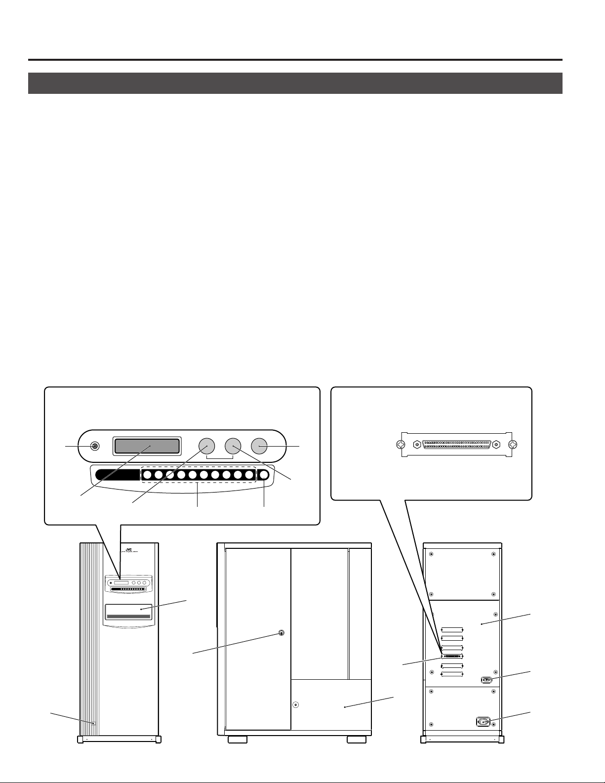
2-1. Front panel, right side panel, rear panel
POWER switch ................... Turns the main unit power on/off. " | ":ON. " ":OFF.
1
POWER Indicator............... Lights up when the POWER switch is turned on. Blinks in case of error during operation.
2
LCD Display Panel............. Shows information using alphanumeric characters.
3
MODE key .......................... Used for LCD display page selection and other operations.
4
SELECT key ....................... Used for switching displayed information and other operations.
5
LOAD/EJECT key ............... Opens or closes the mail slot.
6
ENTER key ......................... Used for LCD page selection and other operations.
7
10-key ................................. Used for selecting tray Nos. and changer SCSI ID Nos. for import/export operations.
8
Mail slot .............................. Used for disc insertion/ejection
9
Key cylinder ....................... After completing the door opening mode, insert a key and turn it counterclockwise to open
0
the door.
Rear panel .......................... Opened and closed when installing or replacing drive units.
!
SCSI connector ................. One SCSI connector port system is provided as standard.
@
RS-232C connector ........... 9-pin D-sub connector (plug) for use in maintenance.
#
AC inlet (main unit) ........... Insert the provided power cord and plug the other end of the power cord to a 120 V-240 V, 50
$
Hz/60 Hz AC power outlet.
Side panel .......................... To be removed in servicing.
%
MC-8200LU (MC-8600LU)
Control panel : the control panel consist of the keys 2 - 8
and the LCD display screen.
LOAD/EJECT
MAIL SLOT
3
POWER
MODE SELECT
1 2 3 4 5 6 7 8 9 0 E
4
8 7
9
0
5
62
SCSI-C
!
@
#
E6
1
%
$
Front panel Right side panel Rear panel
Page 7
Names and Functions of Parts
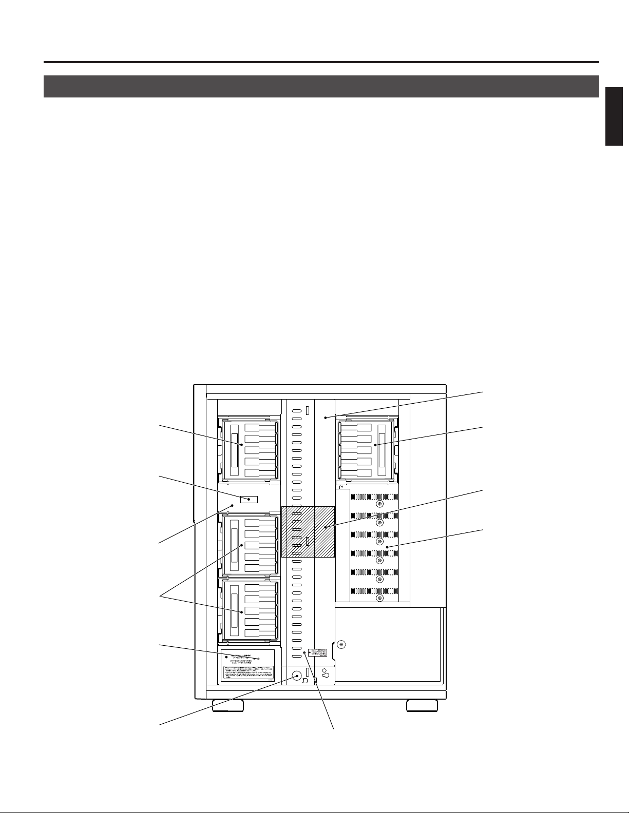
2-2. Interior
Mail slot .............................. Used for disc insertion/ejection.
9
Mail slot transport lock ..... Locks the mail slot during transport.
&
Magazines .......................... Each magazine contains 50 trays accommodating up to 50 discs.
*
Drive bays .......................... Accommodation for up to 6 drive units is compatible with this product. The bays are num-
(
bered 1, 2, 3,4 5 and 6 from the bottom.
Carrier ................................ Tr ansports the trays (discs) between the magazines and the mail slot, drives or printer.
)
Carrier transport lock ....... Locks the carrier during transport.
⁄
Optional carrier transport lock ....
¤
Transport lock screw storage hole ...
‹
(for optional carrier)
Center panel ...................... To be removed only for maintenance, etc. Do not normally remove this panel, as it provides
›
● The system for transporting the trays (discs) between the magazines and the mail slot or drives or printer using
the carrier is generically referred to as the "changer".
To be locked before transport when the MC-CF10U Optional Carrier is installed.
Attach the transport lock screw provided with the MC-CF10U Optional Carrier to this hole.
hazard protection to the parts inside.
ENGLISH
*
&
9
*
‹
Right side panel (when the door is removed.)
›
*
)
(
⁄
¤
E7
Page 8
Names and Functions of Parts
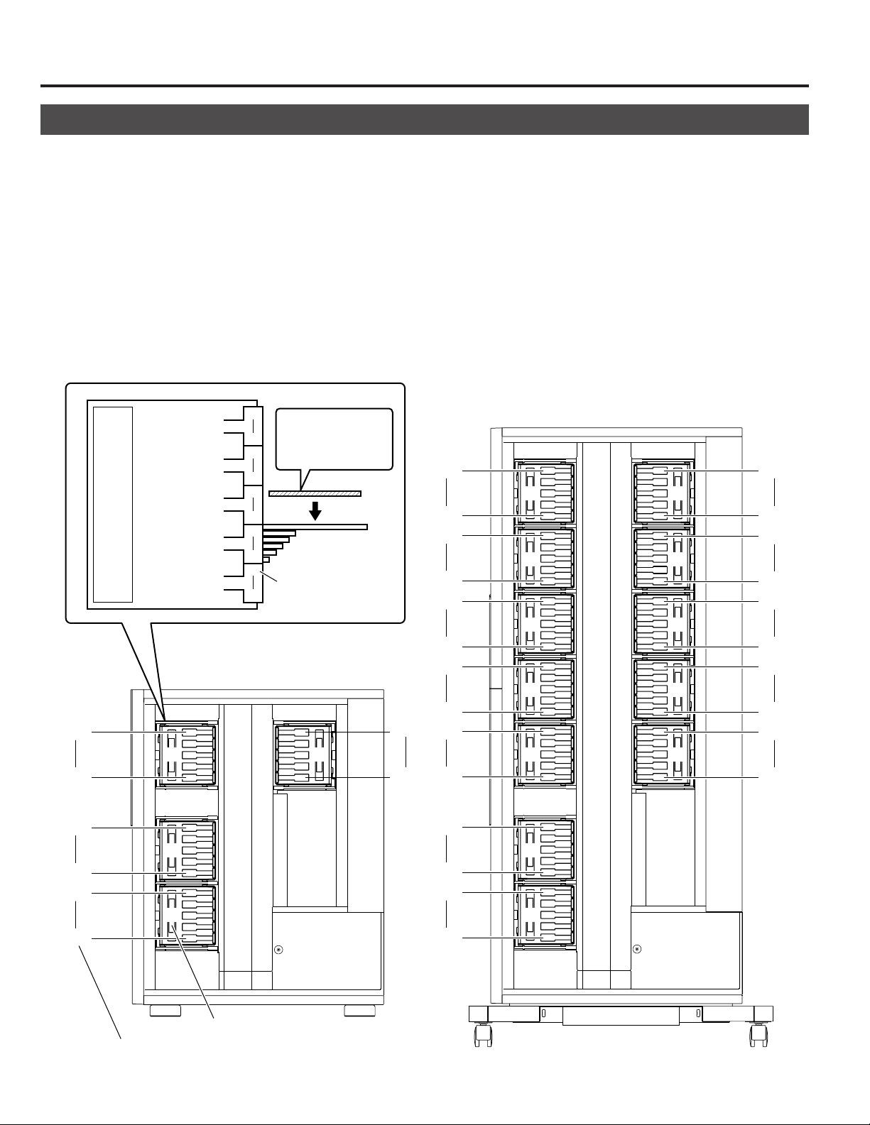
2-3. Magazine numbers, tray numbers, disc numbers
The internal layout of the magazine and the numbers assigned to the magazines, trays and discs are as shown below.
Magazine number...... This is the number assigned to each of the 4 or 12 sets of magazines. The error message dis-
played when a magazine is inserted incompletely refers to the magazine number. (See page E27)
Note, magazine number assignments are different from previous models (MC-1000, MC-2000 and
MC-7000 Series).
Tray number ............... This is the 2-digit number assigned to each of the 50 trays in each magazine. The combination of a
tray number and magazine number corresponds to a disc number. For example, disc number 120
can also be represented as the disc in tray number 20 of magazine number 3. In this way, the disc
can be located in the 20th slot from the bottom of magazine 3.
Disc number .............. This is the 3-digit number assigned serially to every disc in all magazines and trays, starting from
disc number 1 in tray 01 of magazine 1 up to disc number 200 or 600. The error messages usually
refer to the disc numbers. (See page E30)
150
101
3
50
Magazine No. : 3
Tray No. : 20
41
40
Disc No. : 120
31
30
21
20
11
10
Tray No.
01
MC-8200LU
3 4
200
151
350
301
300
251
250
201
200
151
150
101
MC-8600LU
7
6
5
4
3
400
8
351
450
9
401
500
10
451
550
11
501
600
12
551
E8
100
051
050
001
Disc No.
100
2
051
050
1
001
Magazine No.
2
1
Page 9
Names and Functions of Parts
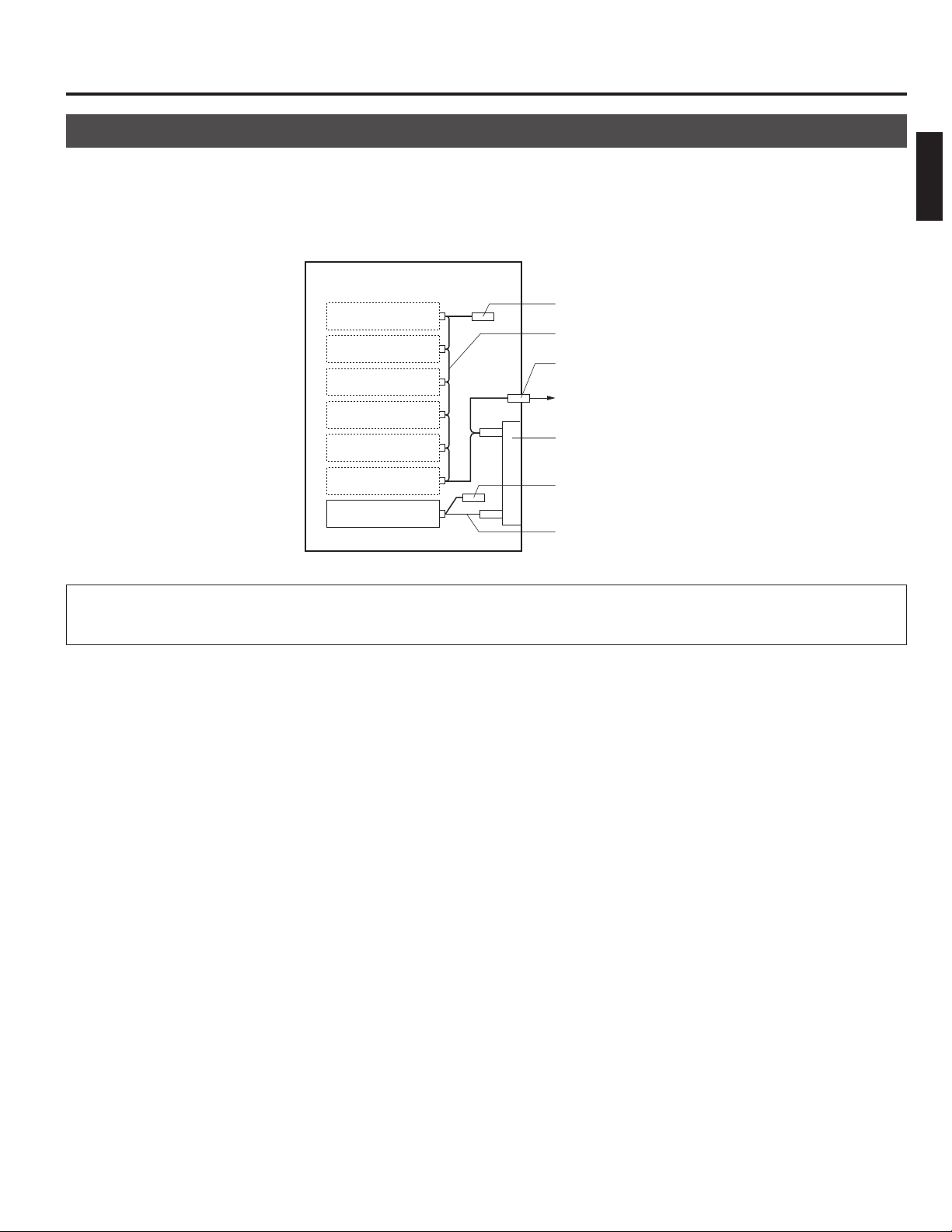
2-4. Internal SCSI cable
The SCSI connections inside the main unit (the Changer) are explained below:
The SCSI board, drive units and an SE (single-ended)/LVC (Low Voltage Differential) conversion board are daisy-chain
connected by an internal SCSI cable. The length of the internal SCSI cable should be about 1.0 meter.
Interior
ENGLISH
Drive 6
Drive 5
Drive 4
Drive 3
Drive 2
Drive 1
Library SCSI board
Terminator
Internal SCSI (LVD) cable
68-pin external SCSI connector
To host computer (SE/LVD)
SE-LVD conversion board
Terminator
Internal SCSI (SE) cable
● Connectors that are not used should be capped in order to prevent short-circuiting.
● The physical extremity of the internal SCSI cable of the changer is terminated.
E9
Page 10

3. SETUP
The standard setup procedure is as shown below. Set up the equipment according to the procedure shown for each model.
MC-8200LU MC-8600LU
Open the transport lock
Removing the transport protective materials
Mount the optional carrier
Install the drive units
Set the SCSI-ID numbers, etc.
Connect the power cord and cables
Execute the automatic drive detection mode.
Turn the power switch on.
Load discs in the magazines
Completion Proceed to the host computer setup
*1
A large number of discs can be loaded quickly(bulk load).
*2
Please have your dealer or nearest JVC service center perform this task.
Start
Attach the casters
*2
*1
P.E10
P.E11
P.E12
P.E22
P.E23
P.E14
P.E25
P.E19, E26
3-1. Attaching the casters
The MC-8600LU comes standard with designated casters.
Three or more persons should attach these casters by following the procedure below.
Please also refer to the caster attaching procedure manual which is provided with the equipment.
1.
After unpacking the equipment, take out the 4 casters
from inside the bottom cushioning material.
2.
Hold each caster with the wheel side down, and insert it
into a caster socket on the bottom panel while sliding
the lock pin as shown below.
Wheel lock lever
*Be sure to lock the wheel
during the attaching operation.
Bar
Lock pin
Wheel
3.
The caster is attached completely when the lock pin
Caster sockets
reaches and engages with the hole on the caster socket.
• Make sure that the pin does not come out even when
the caster is pulled strongly.
CAUTION:
The casters provided together with
the MC-8600LU are exclusively for
preventing the equipment from falling over and for changing its installation place and not for transportation.
Tr ansporting the MC-8600LU on
these casters on an uneven surface over a long distance may
cause them to be damaged.
E10
WARNING
Insert the casters until they are locked completely. Should an incompletely attached
caster comes out, the equipment may fall over
and could cause an injury and damage to the
equipment.
Page 11
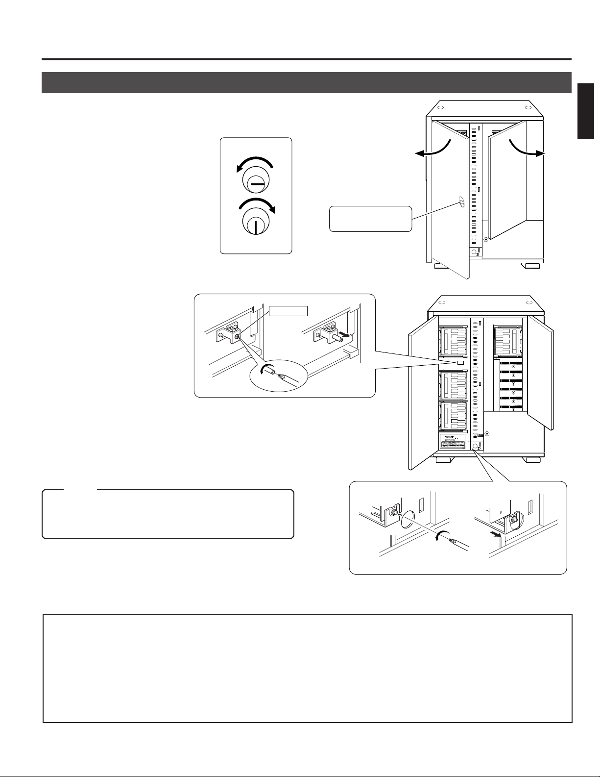
3-2. Opening the transport lock
Lock pin
Door opening/closing
key cylinder
1.
Open the door by inserting the key and turning it
counterclockwise (90°) to unlock the door.
Unlocked
Locked
2.
Open the transport lock of the mail slot.
• Using a philps screwdriver, continue to turn the lock
counterclockwise until the lock is completely disengaged and moves outwards.
Setup
ENGLISH
3.
Open the transport lock of the carrier.
•Continue to turn the screw counterclockwise to loosen
it until the metal device retaining it is disengaged and
moves outwards.
Note:
When using the MC-CF10U Optional Carrier, read "3-4.
Removing the optional carrier transport lock screw"
on page E13 before continuing on.
Proceed to the operation in the next page without closing the door.
• In the case of re-transporting, lock the transport lock as follows:
1) Remove all the discs and turn off the power.
2) Turn on the power while pressing the “1” of the 10-key pad and enter the PACKING mode.
3) Turn off the power as soon as the “END” display appears on the LCD screen.
4) Fix the transport lock as described in
5) When using the MC-CF10U Optional Carrier, read "3-4. Removing the optional carrier transport lock screw" on
page E13 before continuing on.
6) Re-attach the protective transport materials. (a See page E12.)
2
and 3 above.
E11
Page 12

Setup
3-3. Removing the transport protective materials
After opening the transport lock, proceed to the following steps without closing the door.
1.
Remove magazine No. 1.
(a See “9-1. Ejecting/loading the magazines” on page E27.)
TOP
2.
Pull out the protective material forwards.
3 4
2
Protective material
3.
Load magazine No. 1.
(a See “9-1. Ejecting/loading the magazines” on page E27.)
4.
Repeat the same operation for each of the remaining magazines.
TOP
• In the case of re-transporting, it is necessary to remove all the discs and re-attach the protective transport materials
using the reverse procedure to the above. When this operation is required, please consult your dealer or nearest JVCauthorized service agent.
E12
Page 13

Setup
3-4. Removing the optional carrier transport lock screw
When the MC-CF10U is installed, its special transport lock should be removed in addition to its being unlocked as
detailed in "3-2. Opening the transport lock" on page E11. Use the following procedure when unlocking the optional
carrier transport lock.
1.
Remove the transport lock
screw (for optional carrier).
ENGLISH
2.
Insert the removed screw into the desigated storage hole for
the transport lock screw.
• If the system is transported with the MC-CF10U Optional Carrier installed, refer to "3-2. Opening the transport lock",
execute the packing mode and clamp the above-mentioned transport lock screw.
3-5. Installing drives and settings SCSI-ID No., etc.
1.
Installing drives
Install the drives (a See "7. DRIVE UNITS" on page E22).
2.
Initial setting of SCSI-ID No., etc.
The default setting of the SCSI-ID No. of the MC-8200LU/8600LU is "0".
Set the SCSI-ID No. according to your system.
•To change the SCSI-ID No. of the MC-8200LU/8600LU a Read "8. SETTING THE SCSI-ID NUMBERS OF THE MAIN
UNIT" on page E26.
• To set the SCSI-ID Nos. and termination of drives a Read the instruction manuals of the installed drives.
• As the MC-8200LU/8600LU should be turned on to allow its SCSI-ID No. to be set, read "3-6. Connecting the power
cord and cables" on page E14 and connect the power cord before proceeding.
E13
Page 14

Setup
3-6. Connecting the power cord and cables
CAUTION
Tu rn OFF the power of all equipment before starting connections.
Connecting the equipment while power is ON may lead to a malfunction.
To SCSI-C
To the host adapter
of computer
To A C IN
To AC outlet
Always use the power cord provided by JVC. The library system has been designed to conform to
WARNING
s The length of the internal SCSI cable is about 1.0 meter.
s Check the total length of the internal and external SCSI cables. A malfunction may occur if the lengths described below
are exceeded.
1) For use with an LVD: The maximum length of the external cable is 10 meters.
2) For use with an SE (Narrow): The maximum length of the external cable is as follows.
• SCSI-2, 20 Mbytes/s sync: 1.5 meter (Max. 2 drives)
• SCSI-2, 10 Mbytes/s sync: 1.5 meter
• SCSI-2, 5 Mbytes/s async: 4.5 meter
sUse an Ultra 160-compatible cable as the external cable. A malfunction may occur if any other cable is used.
sThe host bus adapter in the controller computer should be LVD compatible.
sRecommended SCSI host adapters and SCSI cables
• WINDOWS server
SCSI host adapter: ASC-29160 by ADAPTEC Co., Ltd.
SCSI cable: ACK-LVD-3M-U320 (3 m) by ADAPTEC Co., Ltd.
• SUN work station
SCSI host adapter: PCI SCSI-2U3WL by Antares Microsystems Co., Ltd.
SCSI cable: ACK-68V-68HD-LVD (2 m) by ADAPTEC Co., Ltd.
“Insulation category Class 1”. In order to assure safety at all times, be sure to ground the system
before use. If other types of power cords other than the specified cord are used, they may overheat and
burn or cause a fire.
Please consult your local JVC service center if a cable of a length other than the above mentioned or one that has been
supplied by another manufacturer has been fitted.
Operation with a recommended host adapter is not guaranteed for a host computer in all cases. An adequate preoperation examination is essential before starting an operation.
E14
Page 15

4. CONTROL PANEL OPERATIONS AND LCD DISPLAY
SELECT
SELECT
1 .NORMAL D I SPLAY
2.ERROR DISPLAY
2
.ERROR DISPLAY
3. ID No.DISPLAY
9
.DRIVE DISPLAY
1.NORMAL DISPLAY
Cursor: Currently selected menu
The switch operation and LCD display system has three operation and display modes as described below.
Normal display ..... This mode includes two patterns, one of which is displayed automatically when the equipment starts
up normally. The disc numbers in the drive units are displayed in real time.
Menu display ........ This mode allows you to start user operations such as SCSI-ID No. checking and setting, internal
history display and door/panel opening.
Event display ........ This mode overrides other modes in case of an event such as initialization after startup, mail slot
operations, setting up the door/panel opening mode or appearance of errors.
4-1. Normal display
Pattern 1 is displayed automatically when the startup has succeeded normally. The display pattern will change every time the
SELECT switch is pressed.
[Pattern 1]
Carrier
Idle Mail slot
CR : – – – MS : – – –
D1 : 0 3 6 D2 : 0 7 5
075
ENGLISH
[Pattern 2]
4-2. Menu display
Pressing the MODE key switch during normal display starts the menu display.
Select a menu by pressing the SELECT key and enter the selection by pressing the MODE key again.
NORMAL DISPLAY
1
(a See "4-1. Normal display" on this page.)
ERROR DISPLAY
2
(a See "10-4. Error history display" on page E32.)
ID No. DISPLAY
3
(a See "8-1. Display for checking the SCSI ID numbers" on page
E26.)
PANEL OPEN
4
DOOR OPEN MODE
5
(a See "5. Door Opening/Closing" on page E18.)
ID No. SET MODE
6
(a See "8. Setup of SCSI ID number of the main unit" on page
E26.)
COUNT DISPLAY
7
(a See "11. Access counts" on page E33.)
IMPORT/EXPORT
8
(a See "6-2. Import/export operation" on page E20.)
DRIVE DISPLAY
9
(a See "7-7. Drive type display" on page E25.)
Drive 3
Drive 1
Disc No.
SELECT SELECT
D3 : NC D4 : NC
D5 : NC
Drive 4Drive 5 Drive 6
D6 : NC
Drive 2
Unconnected
E15
Page 16

Control Panel Operations and LCD Display
4-3. Event display
Power on
1
POWER ON
During initialization
2
When the MC-CF10U Optional Carrier is installed
INITIAL IZING
Error occurrence (a See “10-2. Error code list” on page E31.)
3
Displayed
E
RROR OCCURRED !
alternately.
D ISC=124
CODE = CU
During door opening (a See “5. Door Opening/Closing” on page E18.)
4
E XECUT I NG DOOR
T
OPEN PROCESS
When door is open (a See “5. Door Opening/Closing” on page E18.)
5
D OOR OR PANEL
IS OPEN
Door closing
P USH ENTER KEY
TO RESUME
INITIAL IZING
FL I P CARR I ER
04
HE DOOR
CAN BE OPENED
During mail slot operation (a See “6. Mail Slot” on page E19.)
6
E XPORT DONE
PUSH LOAD KEY
E16
Page 17

Control Panel Operations and LCD Display
POWER ON
1. NORMAL DISPLAY
2. ERROR DISPLAY
Power On
INITIALIZING
Pattern 1
Normal display
Pattern 2
SELECT SELECT
MODE
SELECT
ENTER
Error display 1
3. ID No. DISPLAY
SELECT
SELECT
SELECT
SELECT
ENTER
4. PANEL OPEN MODE
ENTER
SCSI-ID display
Error display 2
Error display 8
SELECT
SELECT SELECT
DR1 :
DR2 :
DR6 :
SELECT
SELECT SELECT
SELECT
SELECT
5. DOOR OPEN MODE
SELECT
ENTER
PUSH SELECT
PUSH SELECT
EXECUTING ...
... CAN BE OPENED
SELECT
SELECT
6. ID No. SET MODE
7. COUNT DISPLAY
8. IMPORT/EXPORT
ENTER
ENTER
ENTER
ENTER
SELECT
9. DRIVE DISPLAY
PUSH SELECT
PUSH SELECT
ID No. display
ID No. entry
SELECT
SELECT
SELECT
ENTER
Input ID No.
SELECT
SELECT
SELECT
9. DR6
SELECT
10. FL
SELECT
SELECT
2. CR
1. TOTAL
PUSH SEL. KEY
PUSH SEL. KEY
Input the start
tray No.
Input the end
tray No.
Start accessing
ENTER
ENTER
*
1
4-4. Display and operation sequence
The sequence of display and operation after turning the power on is as shown below.
ENGLISH
• If the MODE, SELECT or ENTER key has not been pressed within 10
seconds, the current display will return to “Normal display - Pattern 1”
(except in a situation when an event is displayed or the Import/Export Tray
numbers and SCSI-ID numbers are being input).
*1. When the MC-CF10U Optional
Carrier is installed.
E17
Page 18

5. DOOR OPENING/CLOSING
1 . NORMA L D I SP L A Y
2.ERROR DISPLAY
5
.DOOR OPEN MODE
6. ID No.SET MODE
P
USH SELECT KEY
TO OPEN THE DOOR
P
USH SELECT KEY
TO OPEN THE DOOR
E
XECUT I NG DOOR
OPEN PROCESS
T
HE DOOR
CAN BE OPENED
Once the transport locks have been released and the power has been turned on for the first time, the door is locked by an
internal safety lock in addition to the key so that the door cannot be opened with the key alone.
In order to open the door with the key under these conditions, either maintain or turn on the power supply if it has not been
turned on yet, and perform the following operations before inserting and turning the key.
Door Opening
1.
In the normal display mode, press the MODE Key.
(The menu display appears.)
2.
Press the SELECT key 4 times.
("5. DOOR OPEN MODE" appears.)
3.
Press the ENTER key.
(Select and enter "5. DOOR OPEN MODE".)
4.
Press and hold the SELECT key for more than 5 seconds.
(Wait until the display starts to blink.)
5.
Release the SELECT key when the execution display
[EXECUTING DOOR OPEN PROCESS] appears.
* When inserting/ejecting a drive unit, turn off the power after
the completion display [THE DOOR CAN BE OPENED] appears.
6.
Insert the door opening/closing key in the cylinder and
turn it counterclockwise to release the lock and open
the door.
Unlocked
The door opening/closing
Locked
key cylinder (lock)
Door Closing
1.
Close the door and turn the door opening/closing key
clockwise to lock.
2.
Press the ENTER key switch when the display shown
on the right appears.
* The screen will return to the Normal display after initialization.
The door is open.
OOR OR PANE L
D
IS OPEN
The door is closed.
P USH ENTER KEY
TO RESUME
•You cannot perform disc transport operations when the above the door open mode is being executed or the door is open.
E18
Page 19

6. MAIL SLOT
E XPORT DONE
PUSH LOAD KEY
6-1. Disc loading
CAUTION
Do not load or eject a disc before the mail slot has stopped completely.
It may not only damage the disc but also cause the equipment to malfunction because of excessive force being applied
during opening and closing.
Disc loading/ejection method
When a tray is transported to the mail slot under the control of the host computer or the import/export operation
(a P. E20), the mail slot opens automatically when transportation has been completed.
1.
Place a disc gently on the tray with a label surface facing upwards.
(To remove a disc from the tray, hold the disc by the
center hole and the outer edge which is accessible near
the notched section on the front side of the tray.)
CAUTION
Media compatible with the MC-8200LU/8600LU varies
depending on the installed drive types. For details, refer
to the instruction manuals of the drives.
CAUTION
•A DVD-RAM disc may become impossible to write/read
due to dust, fingerprints, scratches, etc. adhering to
the disc surface. Please handle it carefully.
Ta ke special care in handling the DVD-RAM/R discs
because they are extremely vulnerable to scratches
and contamination.
ENGLISH
CAUTION
When using double-sided discs, handle them with special care because they do not have a label on the surface.
2.
Press the LOAD/EJECT key.
(The mail slot closes.)
POWER
•Now you can repeat the open/close operations alternately
by pressing the LOAD/EJECT key provided that the mail
slot transportation operation has not started yet.
• While the carrier is in operation, pressing the LOAD/
EJECT key will not start the open/close operations.
CAUTION
•Never use a damaged and/or warped disc or a disc with an attached label. It will lead to a malfunction of the equipment.
• If you are going to use a disc from a different drive, please check the drive specifications carefully before using it.
(Some drives may not be able to read the disc.)
(At the same time, the equipment may not be able to read the disc which has been written and deleted in a different drive.)
• Note that some double-sided discs do not provide a distinction between the top and bottom sides. Take special care
when removing/loading these discs from/in the MC-8200LU/8600LU.
MODE SELECT
LOAD/EJECT
MAIL SLOT
Label surface
(With a single-sided disc)
E19
Page 20

Mail Slot
1 . NORMA L D I SP L AY
2.ERROR DISPLAY
8
.IMPORT/EXPORT
9.DRIVE D I S P L A Y
P
USH SEL . KEY FOR
IMPORT /EXPORT
I
NPUT START
TRAY No . : – ––
I
NPUT START
TRAY N1o. : 15
I
NPUT END
TRAY No . : – ––
I
NPUT END
TRAY N 1o. : 24
IMP ORT / EXPORT
TRAY No . : 1 15
P
USH SEL . KEY FOR
IMPORT /EXPORT
6-2. Import/export operation
When loading/ejecting discs from any chosen tray by the mail slot without the control of the host computer, follow the procedure shown below.
• During the import/export operation, the host computer commands which include the carrier operations cannnot be executed.
1.
In the normal display mode, press the MODE key.
(The menu display appears.)
2.
Press the SELECT key 7 times.
("8. IMPORT/EXPORT" appears.)
3.
Press the ENTER key.
(Select "8. IMPORT/EXPORT".)
4.
Press and hold the SELECT key for more than 5 seconds.
(Wait until the display starts to blink.)
5.
Release the SELECT key when the input start tray
message is prompted.
6.
Enter the start tray number(001-200*1) using the 10key pad.
•If the number is wrong, input a new 3-digit tray No.(ex.
001) again.
7.
Press the ENTER key.
8.
Enter the end tray number(001-200*1) using the 10-key pad.
•If you wish to use the import/export operation for a
single disc, either enter the same end tray number as
the start tray number or press the ENTER key without
entering any number.
9.
Press the ENTER key.
•You can cancel the following operations by pressing
and holding the ENTER key for 5 seconds during the
import/export operation. If the mail slot opens after
cancelling the operation, press the LOAD/EJECT
key.(The tray in operation will be returned to the magazine; then the import/export operation will be completed.)
1
*
MC-8200LU. (001 - 600 for the MC-8600LU)
E20
Page 21

10.
When the mail slot automatically opens, place the desired disc on the tray (number is displayed on the LCD).
(a See "6-1. Disc loading" on page E19.)
•To remove a disc, lift it out of the tray.
•When the following message appears on the LCD display, it is possible that the transport lock of the mail slot has not
been properly released. Please make sure that that lock pin has been removed completely. (a See "3-2. Opening the
transport lock" on page E11.)
CHECK THE LOCK
PIN!
Press the MODE key to return to the menu display.
11.
Press the LOAD/EJECT key. (The mail slot closes and the tray is returned to the magazine.)
12.
When continuous import/export operations are required, repeat steps 10 and 11.
(The tray number on the LCD display will increment by one.)
•If the tray cannot be found in the magazine (including instances when the tray is in a drive or the color disc printer), this
tray No. will automatically show up on the LCD display and then the import/export operation will be completed.
NO T RA Y
TRAY No .:115
Mail Slot
ENGLISH
Press the MODE key to return to the menu display.
In the following instances, the import/export operation cannot be performed and the LCD display will indicate as shown
on the right.
Clear the following conditions on the host computer side first and
then input again.
• When a tray is in the mail slot.
• When the carrier operation is being executed.
• When the host computer control is prohibiting import/export
operations.
• If the disc location in the main unit (the changer) has been altered or the contents of a disc have changed bacause of
import/export operations, the disc location data on the host computer should, as a rule, be renewed.
(Hardware and software must stay in sync for proper operation).
IMPORT /EXPORT
IS PROH I B I TED
E21
Page 22

7. DRIVE UNITS
A
A
CAUTION
• Make sure that the power is turned off when installing/removing, connecting or setting a drives.
Performing these operations while the power is on will result in the equipment malfunctioning.
Be sure to read the instruction manuals of the drive units before proceeding to any of the following work.
• Note that certain device drivers are incompatible with the simultaneous use of more than one type of drive (mixed use).
Please consult your dealer or nearest JVC service center.
7-1. Removing the panel
1.
Open the door.
(a See "5. Door Opening/Closing" on page E18.)
2.
Tu rn off the power.
3.
Remove the drive bay panel.
• Remove the 4 screws.
• Carefully disconnect the SCSI cable from the drive.
(a See "7-4 Connecting the cables" on page E23.)
• Unplug both the internal SCSI (SE) cable (50P cable)
and the LVD power cable (6P cable) from the connectors on the SE-LVD conversion board.
7-2. Installing the drive units
• When removing the drive units, be sure to disconnect the control cable and power cable beforehand.
(a See "7-4. Connecting the cables" on page E23.)
1.
Inserting a drive unit.
• Always insert it into a bay with the lowest available
bay No.(from bottom to top)
• Be careful not to snag any cables.
• Be careful not to damage the sensor slit.
2.
Secure the drive using the provided metric screws.
• The provided metric screws are attached to the optional drive unit.
CAUTION
Be sure to attach the screws securely. If the library system is operated without the screws, either the library or
the drives may be damaged.
* Be careful not
to damage the
sensor slit.
Sensor slit
E22
Page 23

Drive Units
7-3. Setting the SCSI-ID Numbers, etc.
s Procedure for setting the SCSI-ID No. and other jumper settings.
Please refer to the specified section(s) of the corresponding drive instruction manual.
s Make sure to turn the power OFF before starting the procedure. If the procedure is carried out with the power ON, it will
cause malfunction.
s The new ID Nos. will become effective from the the moment the power is turned on.
s The new SCSI ID Nos. should not conflict with the ID Nos. of other SCSI equipment on the same SCSI bus.
s The SCSI ID numbers should be in the range from 0 to 7. Numbers from 8 to 15 cannot be used.
7-4. Connecting the cables
s For the positions of the connectors for the cables from
the optional drives, please refer to the relevant instruction manuals for the drives.
1.
Connect the control cable (14P).
• Connect the control cable having the same number
as the drive bay number.
2.
Connect the power cable (14P).
(The figure shows the case of the MC-R434U.)
3.
Connect the two LVD power cables (6P) to the SE-LVD
conversion board.
• Both cables have identical connector types, so that
either cable can be connected to either connector on
the SE-LVD conversion board.
Internal SCSI (LVD) cable
<MC-R433 rear panel>
NW
68p
1.
2.
Control cable
14p
DIP switch
4p
Power cable
ENGLISH
4.
Connect the internal SCSI (SE) cable (50P) to the SELVD conversion board.
• The other end of the internal SCSI (SE) cable is connected to the library SCSI board in the library.
5.
Connect the internal SCSI (LVD) cable (68P) to the
drives.
• The other end of the internal SCSI (LVD) cable is connected to the SE-LVD conversion board.
Internal SCSI cable (approx. 1.0 m)
Te r minator
Drive 6
Drive 5
Drive 4
Drive 3
Drive 2
Drive 1
Te r minator
Library SCSI board
Internal SCSI (SE)
cable
To SE-LVD conversion board
Library
4.
5.
< SE-LVD conversion board >
Internal SCSI (SE) cable
50p
6p
3.
68p
Internal SCSI (LVD) cable
To each drive
6p
LVD power
cable
E23
Page 24

D ETECT I NG DR I VES
.....PLEASE WAIT
D
RIVE DETECTION
COMPL EED
Drive Units
7-5. Installing the panels
CAUTION
s Check the installation screws and cables before installing the panel. Insufficient connections may cause malfunctions.
1.
Attach rear and side panels.
• Screw the panels on, following the procedure in "7-1 Removing the panel" on page E22 in the reverse order.
2.
Close the door
(a See "5. Door Opening/Closing" on page E18.)
7-6. Automatic drive detection mode
Note:
After installing, adding, exchanging or removing drives, be sure to execute the auto drive detection mode to prevent any malfunction.
1.
While holding the "8" key on the control panel, turn on
the MC-8200LU/8600LU.
2.
When the LCD display shows "DRIVE DETECTION
COMPLETED", turn off the power of the MC-8200LU/
8600LU.
3.
Tu rn the MC-8200LU/8600LU on again.
E24
Page 25

7-7. Drive type display
U NKNOWN DR I VE
TYPE DETECTED
Check the types of the installed drives as follows.
1.
Press the MODE key while the LCD display is in normal display mode (to display Menu display).
2.
Press the SELECT key 8 times (to display "9. DRIVE
DISPLAY").
3.
Press the ENTER key (to select "9. DRIVE DISPLAY").
4.
The type of the drive in each drive bay will be displayed.
(Each press of the SELECT key displays the information on the next drive.)
Drive Units
1 .NORMAL DISPLAY
2.ERROR DISPLAY
.DRIVE DISPLAY
9
1.NORMAL DISPLAY
R1 :DVD–RAM
D
DR2 : ROM / R e t c
SELECT
ENGLISH
SELECT
R2 :ROM/R et c
DDR3 :ROM/R et c
SELECT
R6 :NO DRI VE
D
DR1 : DVD–RAM
Meaning of the display
"DVD-RAM" : DVD-RAM/R drive
"NO DRIVE" : Drive is not connected or installed
"ROM/R etc" : Non DVD-RAM/R drive (CD-ROM/R, DVD-ROM, etc.)
"UNKNOWN" : When drive detection mode has not been executed.
● If the automatic drive detection mode has not been executed, the
LCD displays “UNKNOWN DRIVE DETECTED”.
● If the type displayed for an installed drive is erroneous or if [NO DRIVE] or [UNKNOWN] is displayed, the cable connection to the
drive may be missing or the wrong one. Check the cable connection and drive type again.
E25
Page 26

8.
SETTING THE SCSI-ID NUMBERS OF THE MAIN UNIT
Perform the following operations when changing the setting of the SCSI-ID Nos. of the main unit (changer).
1.
In the normal display mode, press the MODE switch.
(the menu display returns.)
2.
Press the SELECT key 5 times.
("6. ID No. SET MODE" appears.)
3.
Press the ENTER key.
(Select and enter "6. ID No. SET MODE".)
4.
Press and hold the SELECT key for more than 5 seconds.
(Wait until the display starts to blink.)
5.
Release the SELECT key when the current ID No. is
displayed.
6.
Select a new ID No. using the keys 0 to 7.
1 .NORMA L D I SPLAY
2.ERROR D I S P L AY
6
.ID No.SETMODE
7.COUNT DISPLAY
USH SELECT KEY
P
TO CHANGE I D No .
P
USH SELECT KEY
TO CHANGE I D No .
HANGER
C
SCS I I D No . = 0
HANGER
C
SCS I I D No .=3.
7.
Press the ENTER key. (The ID No. being displayed is
entered.)
• The set ID No. becomes effective from the next time
power is turned on.
s The new SCSI ID Nos. should not conflict with the ID Nos. of other SCSI equipment on the same SCSI bus.
s The SCSI ID numbers should be in the range from 0 to 7. Numbers from 8 to 15 cannot be used.
s If the server connected to the changer runs Windows 2000 as the OS, the operations may be unstable. To ensure stable
operation, change the SCSI ID No. of the changer to an unused number, for example 6.
C HANGER I D No .
IS SET TO 3
8-1. Display for checking the SCSI ID numbers
Perform the following operations when display of the current SCSI-ID Nos. of the main unit and the drive units is required.
1.
In the normal display mode, press the MODE key.
(the menu display appears.)
2.
Press the SELECT key twice.
("3. ID No. DISPLAY" appears.)
3.
Press the MODE key.
(Select and enter "3. ID No. DISPLAY".)
The following will be displayed.
CH: Changer
DR1 - 6: Drive 1-6 ("-" indicates "Not Connected")
1 .NORMAL DISPLAY
2.ERROR D I S P L AY
3 .ID No.DISPLAY
4.PANEL OPEN
C HDR123456
0 12––––
E26
Page 27

9. MAGAZINES
CAUTION
• Do not use a magazine which has been damaged (e.g. dropped), as normal operation cannot be accomplished with
such a magazine. In addition, the use of such a magazine may damage the internal mechanism.
• The magazines and trays used with the MC-1000/2000 series CD-ROM Library and MC-7000 series DVD-RAM Library are
not compatible with those used with the MC-8000 series CD/DVD Library. Do not interchange the magazines and trays
between these models, as this will damage the equipment.
• If it is required to take out or attach a magazine during operation, be sure to perform optimum software processing at the host
in advance.
9-1. Ejecting/loading the magazines
Ejection
1.
Open the door. (a See “5. Door Opening/Closing” on page E18.)
*
Do not turn off the power switch.
2.
Pull the release lever toward the front.
• The magazine unlocks and comes out slightly toward the front.
Be careful not to get your finger caught between the release
lever and grip.
3.
Pull the magazine straight toward the front.
• Use care not to hit or drop the magazine.
• Be careful not to touch the tray lock by mistake.
A tray may spring out.
Loading
1.
Check the orientation of the magazine.
• The [c TOP] marking is provided on the grip to indicate the
upper direction of the magazine.
2.
Align the magazine rails with the guide on the main unit (changer)
and insert it straight forward.
• Insert the magazine slowly. Inserting it with a strong force may
damage the equipment.
• Ensure that the magazine guides are fitted in the guides located at the left or right sides of the library (both at the top and
bottom of the sides).
3.
Push in the magazine completely until it stops.
• Then, pull the magazine slightly toward the front to ensure that
it is locked.
4.
Close the door (See "5. Door Opening/Closing" on page E18.)
Release lever
2
3
Grip
T
O
P
Tray lock
The magazine guides are fitted in
the guides located at the left and
right sides of the library.
TOP
ENGLISH
*
If a magazine was removed and installed and then the door closed
after the power has been turned on, this function will automatically
check the disc status inside the magazine.(provided that the automatic disc checking function has been turned ON
AP.E29
).
Display in case of incomplete insertion
The front panel display will indicate an error if the door is closed while the magazine insertion is incomplete. Check the
incorrectly inserted magazines from the displayed message and re-insert them completely until they are locked.
E RROR OCCURRED !
D
ISC=
CODE =CC-31
---
RMG-2
E
R
--
-- -
Display when the insertion of magazine
Nos. 2 and 11 are unsuccessful.
--11
-
E27
Page 28

Magazines
9-2. Loading/replacing the discs
CAUTION
• When loading discs directly into the magazine trays without using the mail slot, be careful not to damage the magazines
and trays.
•A disc may become impossible to write/read due to dust, fingerprints, scratches, etc. adhering to the disc surface.
Please handle it carefully.
•Take special care in handling the DVD-RAM discs because they are extremely vulnerable to scratches and contamination.
• Media compatible with the MC-8200LU/8600LU varies depending on the drive configuration. For details, refer to the instruction manuals of the drives.
When using double-sided discs, handle them with special care because they do not have a label on the surface.
• Never use a damaged and/or warped disc or a disc with an attached label. It will lead to a malfunction of the equipment.
• If you are going to use a disc which has been used with this equipment from a different drive, please check the drive
specifications carefully before using it.
(Some drives may not be able to read the disc.)
(At the same time, the equipment may not be able to read the disc which has been written and deleted in a different drive.)
• Note that some double-sided discs do not provide a distinction between the top and bottom sides. Take special care when
removing/loading these discs from/in the MC-8200LU/8600LU.
1.
Eject a magazine. (a See “9-1. Ejecting/loading the
magazines” on page E27.)
2.
Unlock the tray lock corresponding to the tray to be used.
(a See “2-3. Magazine numbers, tray numbers, disc
numbers” on page 8.)
30
21
3.
Pull out the tray.
4.
Place the disc on the tray.
Label surface
(With a single-sided disc)
CAUTION
(1) Place the disc correctly on the disc tray so that it does
stay in the guide section of the disc tray.
(2) To prevent projection of a tray or incomplete locking
of the tray lock, align the edges of all the trays in the
magazine by slightly pushing them inward from the
top to the bottom with you finger.
5.
Push in the tray and lock the tray lock.
6.
Load the magazine in the changer. (a See “9-1. Ejecting/loading the magazines” on page E27.)
E28
(3) Always handle the magazine the correct way.
Holding or placing a magazine upside down or on its
side may cause the discs to slip out of position and
result in malfunction.
Page 29

Magazines
9-3. Automatic disc checking function
If a magazine was removed and reinstalled after the power had been turned on, this function will automatically check the disc
status inside the magazine.
Checking the operation modes.
Press and hold the MODE switch for more than 5 seconds.
• The factory default setting for the automatic disc checking function is on.
ENGLISH
Automatic disc checking function ON
A UTO D I SCCHECK :
ON
Switching the operation modes
Operation modes will alternate (toggle) when you turn the power off, and then on while pressing both the SELECT and the
LOAD/EJECT keys simultaneously.
sDepending on the management software used, you may still have to update the disc status data of the host computer
even after the automatic disc checking function has updated the disc status data of a magazine.
Automatic disc checking function OFF
A UTO D I SC CHECK :
OFF
E29
Page 30

10. ERROR CODES
In the event an error, the control panel indicator blinks and the LCD shows the error details by overriding any other information.
POWER
The indicator blinks.
10-1. Error code explanation
LCD displays in the event of error
ERROR OCCURRED !
If the transport lock of the carrier
has not been opened, this section
shows "CHECK CAR. SCREW".
DISC = 124
CODE = CU
ERR MG – 2 – – –
– – – – – 1 –1
-
07
Display when
CODE = CC-31
MODE SELECT
LOAD/EJECT
MAIL SLOT
DISC = 124
Disc No.
-
CODE = CU
Disc No. : Shows the disc No. being accessed at the moment of error
occurrence. "---" is displayed if no disc is accessed at the moment
of error occurrence.
07
Error code
Unit detail code
Unit in error
Units in error and unit detail codes
Unit in error Unit detail code
U Up/down
L Tray lock
C Carrier
M Mail slot
D1 to D4 Drive
C Catcher
D Disc
F Flip
E Ejection
L Loading
T Tray
T Tray
C Clamp
E Ejection
D Disc
S Spindle
• When an error occurs, write down the error code before turning the power off, except in the case of an urgent problem
such as smoke.
• When an error occurs, make sure not to turn off the power in order to prevent further problems such as disc damage, and
contact your dealer or nearest JVC service center immediately.
E30
Page 31

10-2. Error code list
Error Codes
Device
CU04 UP/DOWN motor does not function
CL11 Tray lock impossible, or lane change not possible
CC26 Right catcher sensor does not turn on
CD
ML 51 Mail Slot loading is not possible
(D#)*
*1: # represents the drive number.
*2: Check the magazine loading condition. (
Device
part
F
E50Mail Slot ejecting is not possible
T52Destination-unknown tray exists in the Mail Slot
T
1
C62Disc clamp of the drive does not function
E63Drive ejection is not possible
D64Failure to remove the disc from the drive
S65Spindle motor fails to stop (Ejection inhibited status)
Error
code
01 UP/DOWN rotary sensor does not change
02 Left slit sensor does not change
03 Right slit sensor does not change
07 UP/DOWN motor drive short-circuits and over-current is detected
08 UP/DOWN operation exceeds the predetermined duration
09 Lower limit sensor turn on during UP/DOWN operation
10 Tray lock release not possible
12 Tray lock does not exist at the initial position during carrier movement
20 Catcher (right → left) movement operation exceeds the predetermined duration
21 Catcher (left → right) movement operation exceeds the predetermined duration
22 Catcher (right → left) convergence operation exceeds the predetermined duration
23 Catcher (left → right) convergence operation exceeds the predetermined duration
24 Catcher (right → left) tray rotary sensor does not change
25 Catcher (left → right) tray rotary sensor does not change
27 Left catcher sensor does not turn on
28 Catcher motor (right → left) does not function
29 Catcher motor (left → right) does not function
30 Tray does not exist
2
31*
32 Over-current is detected during catcher motor operation
41 Destination-unknown tray exists on the carrier
42 No disc in the tray
43 Flip tray does not exist
80 During the flip raise operation, the expected time required is over
81 During the flip descent operation, the expected time required is over
60 Destination-unknown tray exists in the Drive and the control cable of the Drive is disconnected.
61 Tray removal is not possible at the drive position
Magazine insertion incomplete, or sensor defective
See “9-1. Ejecting/loading the magazines” on page E27.)
a
Description
ENGLISH
10-3. How to cancel the Error "64"
Please have your dealer or local JVC-authorized service agent perform this work.
Error “64” occurs when the removal of a disc from a drive fails or when the position of a disc on the tray is unstable.
During the occurrence of Error "64", even if the power is turned ON again, the unit will not startup. Perform the following operation:
1.
Open the door and remove the side and center panels.
2.
Remove both the disc and the tray from the drive and
that is on the carrier. Contact JVC for assistance.
3.
Close the door, then while pressing the '0' key, turn the
power ON.
* If the cancellation of the Error "64" is performed without removing
the disc and tray from the carrier, damage to either or both of them
may result.
E31
Page 32

Error Codes
10-4. Error history display
The history of past errors can be displayed as described below.
1.
In the normal display mode, press the MODE key.
(The menu display appears.)
2.
Press the SELECT key once.
("2. ERROR DISPLAY” appears.)
3.
Press the ENTER key.
(Select “2. ERROR DISPLAY".)
"NO ERROR FOUND” appears if no error has occurred
in the past.
If there is any past error, the data on the latest 8 error
occurrences can be recalled from memory and displayed.
4.
Press the SELECT key to display the data on past errors in sequence.
Error history
The smaller the number,
the more recent the error
occurred.
Error codeDisc No.
1 . NORMAL DISPLAY
2 . ERROR DISPLAY
2 . ERROR DISPLAY
3 . ID NO. DISPLAY
ER1 : 107 – CU08
–CC20 – CL10 – CU02
When there is
no error history
NO ERROR FOUND
* If a certain error has a history
of successive occurrences, the
second and later errors are
shown in the second line. The
data is displayed in a single line
when there are no successive
errors.
ER1 : 107-CU08
-
CC20-CL10-CU02
Error codes
ER8 : 125 – CD41
● This data may be lost if the equipment is disconnected from the power source for more than six months.
10-5. Troubleshooting
When the following conditions occur, check items listed on the right.
Conditions Causes
The host PC runs Windows 2000 as the OS and the ID No. of the
Library is left to 0. (a P. E26)
The SCSI cable is not an Ultra 60-compatible cable. . (a P. E14)
The changer or drives cannot be recognized by the host computer.
The drive is identified but a disc cannot be transported to the drive.
Read (write) errors occur.
The initial setup of the SCSI device is not possible using a driver software.
The LCD display shows "UNKNOWN DRIVE TYPE DETECTED".
A wrong setting of the SCSI board in the host PC was made or the
cable length exceeds the specific length. (a P. E14)
The drive unit SCSI connector is improperly connected. (a P. E23)
The drive unit power cable is improperly connected. (a P. E23)
Overlapping of the SCSI-ID Nos. has occurred. (
The drive unit control cable is improperly connected. (a
The disc is either dirty or damaged. (a P. E5)
The SCSI cable is not an Ultra 60-compatible cable. (a P. E14)
A wrong setting of the SCSI board in the host PC was made or the
cable length exceeds the specific length. (a P. E14)
The drive unit control cable is improperly connected. (
a
SCSI ID Nos. are conflicting. (
The drive detection mode has not been executed. (
P. E14, E23)
a
P. E15, E23)
P.E15, E23
a
P. E23)
a
P. E25)
)
E32
Page 33

11. ACCESS COUNTS
Access counts of the main unit (changer) and each unit (carrier, drives 1 - 6 and color disc printer) can be checked using this
function.
1.
In the normal display mode, press the MODE switch.
(The menu display appears.)
2.
Press the SELECT key 6 times.
("7. COUNT DISPLAY" appears.)
3.
Press the ENTER key.
(Select "7. COUNT DISPLAY".)
4.
Pressing the SELECT key changes the display.
1. TOTA L: The total access count for the Library.
2. CR : Carrier
3. MS : Mail slot
4. DR1 : Drive 1
5. DR2 : Drive 2
6. DR3 : Drive 3
7. DR4 : Drive 4
8. DR5 : Drive 5
9. DR6 : Drive 6
10. FL : Flip
()
Only when the MC-CF10U Optional Carrier is installed
1 .NORMAL DISPLAY
2.ERROR D I S P L AY
. COUNT D I SP L A Y
7
8. IMPORT/EXPORT
.TOTAL:000237
1
2. CR :0 00179
.CR
2
3. MS
: 000179
: 000020
ENGLISH
SELECT
.DR6:000004
9
1.TOTAL:000237
SELECT
.TOTAL:000237
1
2. CR :000179
s Access counts of unconnected drive units will appear as[------].
s The initial "TOTAL" access count from the factory may be "999880-999999".
s This data may be lost if the equipment is disconnected from the power source for more than six months.
SELECT
E33
Page 34

SPECIFICATIONS
Item
Number of stored discs
Number of magazines
Operating environment
Rated power voltage
Rated power frequency
Rated current
Power consumption
Interface
Drive slots rack bays
Media size
Applicable
options
Weight
Drives
Carrier
Magazine
MC-8200LU
200
4
Temperature: 5°C to 35°C (41°F to 95°F) (Note 1) Humidity: 10% to 80% (no condensation)
AC 120 V to 240 V
50 Hz/60 Hz
2.4 A to 1.4 A (max. value), 1.4 A to 0.8 A (6 Drives are loaded)
140 W (Reference value, 6 DVD-RAM drives are loaded)
68-pin external SCSI connector
6
12 cm discs
Available drives
DVD-RAM/R
drive
• The relevant specifications for the drives can be found in the appropriate instruction manual.
• Concerning the Availability/Compatibility of the drives that are not listed, please contact your dealer
or nearest JVC service centre.
• The production of a particular drive may be discontinued without prior notice. Therefore,
a replacement drive may be changed to a different model.
• JVC does not provide a warranty in the case of software not functioning correctly as a result of a
drive being replaced or added.
Single-sided / Double-sided compatible disc carrier: MC-CF10U
Magazine set: MC-M25U (B)
(Excluding the discs and optional equipment)
58kg
MC-R434U Write/Read
Read
DVD-RAM (Ver. 2.1), DVD-R (for General), CD-R, CD-RW
DVD-ROM, CD-ROM
104kg
MC-8600LU
600
12
3.2 A to 1.8 A (max. value), 1.4 A to 0.8 A (6 Drives are loaded)
Compatible discs
(Excluding the discs and optional equipment)
Dimensions
(Unit: mm)
View when the door
is open (Top view)
MC-8200LU
MC-8600LU
866
1641
340
360
340
670
670
272
572
Design and specifications are subject to change without notice.
Note 1 : When using 6 of the MC-R434U units together, be sure that the room temperature is between 5 °C and 30 °C.
E34
777 807
Page 35

MC-8200LU/MC-8600LU CD/DVD LIBRARY
is a registered Trademark owned by VICTOR COMPANY OF JAPAN, LTD.
is a registered Trademark in Japan, the U.S.A., the U.K. and many other countries.
© 2003 VICTOR COMPANY OF JAPAN, LIMITED
VICTOR COMPANY OF JAPAN, LIMITED
Printed in Japan
LST0168-001A
 Loading...